US6152580A - Apparatus and method for producing collimated light from an area source - Google Patents
Apparatus and method for producing collimated light from an area source Download PDFInfo
- Publication number
- US6152580A US6152580A US09/024,481 US2448198A US6152580A US 6152580 A US6152580 A US 6152580A US 2448198 A US2448198 A US 2448198A US 6152580 A US6152580 A US 6152580A
- Authority
- US
- United States
- Prior art keywords
- light
- tiled
- flat
- panel display
- display
- Prior art date
- Legal status (The legal status is an assumption and is not a legal conclusion. Google has not performed a legal analysis and makes no representation as to the accuracy of the status listed.)
- Expired - Lifetime
Links
Images

Classifications
-
- G—PHYSICS
- G02—OPTICS
- G02F—OPTICAL DEVICES OR ARRANGEMENTS FOR THE CONTROL OF LIGHT BY MODIFICATION OF THE OPTICAL PROPERTIES OF THE MEDIA OF THE ELEMENTS INVOLVED THEREIN; NON-LINEAR OPTICS; FREQUENCY-CHANGING OF LIGHT; OPTICAL LOGIC ELEMENTS; OPTICAL ANALOGUE/DIGITAL CONVERTERS
- G02F1/00—Devices or arrangements for the control of the intensity, colour, phase, polarisation or direction of light arriving from an independent light source, e.g. switching, gating or modulating; Non-linear optics
- G02F1/01—Devices or arrangements for the control of the intensity, colour, phase, polarisation or direction of light arriving from an independent light source, e.g. switching, gating or modulating; Non-linear optics for the control of the intensity, phase, polarisation or colour
- G02F1/13—Devices or arrangements for the control of the intensity, colour, phase, polarisation or direction of light arriving from an independent light source, e.g. switching, gating or modulating; Non-linear optics for the control of the intensity, phase, polarisation or colour based on liquid crystals, e.g. single liquid crystal display cells
- G02F1/133—Constructional arrangements; Operation of liquid crystal cells; Circuit arrangements
- G02F1/1333—Constructional arrangements; Manufacturing methods
- G02F1/1335—Structural association of cells with optical devices, e.g. polarisers or reflectors
- G02F1/133524—Light-guides, e.g. fibre-optic bundles, louvered or jalousie light-guides
-
- G—PHYSICS
- G02—OPTICS
- G02F—OPTICAL DEVICES OR ARRANGEMENTS FOR THE CONTROL OF LIGHT BY MODIFICATION OF THE OPTICAL PROPERTIES OF THE MEDIA OF THE ELEMENTS INVOLVED THEREIN; NON-LINEAR OPTICS; FREQUENCY-CHANGING OF LIGHT; OPTICAL LOGIC ELEMENTS; OPTICAL ANALOGUE/DIGITAL CONVERTERS
- G02F1/00—Devices or arrangements for the control of the intensity, colour, phase, polarisation or direction of light arriving from an independent light source, e.g. switching, gating or modulating; Non-linear optics
- G02F1/01—Devices or arrangements for the control of the intensity, colour, phase, polarisation or direction of light arriving from an independent light source, e.g. switching, gating or modulating; Non-linear optics for the control of the intensity, phase, polarisation or colour
- G02F1/13—Devices or arrangements for the control of the intensity, colour, phase, polarisation or direction of light arriving from an independent light source, e.g. switching, gating or modulating; Non-linear optics for the control of the intensity, phase, polarisation or colour based on liquid crystals, e.g. single liquid crystal display cells
- G02F1/133—Constructional arrangements; Operation of liquid crystal cells; Circuit arrangements
- G02F1/1333—Constructional arrangements; Manufacturing methods
- G02F1/1335—Structural association of cells with optical devices, e.g. polarisers or reflectors
- G02F1/1336—Illuminating devices
-
- G—PHYSICS
- G09—EDUCATION; CRYPTOGRAPHY; DISPLAY; ADVERTISING; SEALS
- G09F—DISPLAYING; ADVERTISING; SIGNS; LABELS OR NAME-PLATES; SEALS
- G09F13/00—Illuminated signs; Luminous advertising
- G09F13/04—Signs, boards or panels, illuminated from behind the insignia
- G09F13/0409—Arrangements for homogeneous illumination of the display surface, e.g. using a layer having a non-uniform transparency
-
- G—PHYSICS
- G09—EDUCATION; CRYPTOGRAPHY; DISPLAY; ADVERTISING; SEALS
- G09G—ARRANGEMENTS OR CIRCUITS FOR CONTROL OF INDICATING DEVICES USING STATIC MEANS TO PRESENT VARIABLE INFORMATION
- G09G3/00—Control arrangements or circuits, of interest only in connection with visual indicators other than cathode-ray tubes
- G09G3/20—Control arrangements or circuits, of interest only in connection with visual indicators other than cathode-ray tubes for presentation of an assembly of a number of characters, e.g. a page, by composing the assembly by combination of individual elements arranged in a matrix no fixed position being assigned to or needed to be assigned to the individual characters or partial characters
-
- G—PHYSICS
- G02—OPTICS
- G02F—OPTICAL DEVICES OR ARRANGEMENTS FOR THE CONTROL OF LIGHT BY MODIFICATION OF THE OPTICAL PROPERTIES OF THE MEDIA OF THE ELEMENTS INVOLVED THEREIN; NON-LINEAR OPTICS; FREQUENCY-CHANGING OF LIGHT; OPTICAL LOGIC ELEMENTS; OPTICAL ANALOGUE/DIGITAL CONVERTERS
- G02F1/00—Devices or arrangements for the control of the intensity, colour, phase, polarisation or direction of light arriving from an independent light source, e.g. switching, gating or modulating; Non-linear optics
- G02F1/01—Devices or arrangements for the control of the intensity, colour, phase, polarisation or direction of light arriving from an independent light source, e.g. switching, gating or modulating; Non-linear optics for the control of the intensity, phase, polarisation or colour
- G02F1/13—Devices or arrangements for the control of the intensity, colour, phase, polarisation or direction of light arriving from an independent light source, e.g. switching, gating or modulating; Non-linear optics for the control of the intensity, phase, polarisation or colour based on liquid crystals, e.g. single liquid crystal display cells
- G02F1/133—Constructional arrangements; Operation of liquid crystal cells; Circuit arrangements
- G02F1/1333—Constructional arrangements; Manufacturing methods
- G02F1/13336—Combining plural substrates to produce large-area displays, e.g. tiled displays
-
- G—PHYSICS
- G02—OPTICS
- G02F—OPTICAL DEVICES OR ARRANGEMENTS FOR THE CONTROL OF LIGHT BY MODIFICATION OF THE OPTICAL PROPERTIES OF THE MEDIA OF THE ELEMENTS INVOLVED THEREIN; NON-LINEAR OPTICS; FREQUENCY-CHANGING OF LIGHT; OPTICAL LOGIC ELEMENTS; OPTICAL ANALOGUE/DIGITAL CONVERTERS
- G02F1/00—Devices or arrangements for the control of the intensity, colour, phase, polarisation or direction of light arriving from an independent light source, e.g. switching, gating or modulating; Non-linear optics
- G02F1/01—Devices or arrangements for the control of the intensity, colour, phase, polarisation or direction of light arriving from an independent light source, e.g. switching, gating or modulating; Non-linear optics for the control of the intensity, phase, polarisation or colour
- G02F1/13—Devices or arrangements for the control of the intensity, colour, phase, polarisation or direction of light arriving from an independent light source, e.g. switching, gating or modulating; Non-linear optics for the control of the intensity, phase, polarisation or colour based on liquid crystals, e.g. single liquid crystal display cells
- G02F1/133—Constructional arrangements; Operation of liquid crystal cells; Circuit arrangements
- G02F1/1333—Constructional arrangements; Manufacturing methods
- G02F1/1335—Structural association of cells with optical devices, e.g. polarisers or reflectors
- G02F1/1336—Illuminating devices
- G02F1/133602—Direct backlight
- G02F1/133606—Direct backlight including a specially adapted diffusing, scattering or light controlling members
- G02F1/133607—Direct backlight including a specially adapted diffusing, scattering or light controlling members the light controlling member including light directing or refracting elements, e.g. prisms or lenses
-
- G—PHYSICS
- G09—EDUCATION; CRYPTOGRAPHY; DISPLAY; ADVERTISING; SEALS
- G09G—ARRANGEMENTS OR CIRCUITS FOR CONTROL OF INDICATING DEVICES USING STATIC MEANS TO PRESENT VARIABLE INFORMATION
- G09G2300/00—Aspects of the constitution of display devices
- G09G2300/04—Structural and physical details of display devices
- G09G2300/0421—Structural details of the set of electrodes
- G09G2300/0426—Layout of electrodes and connections
Definitions
- the present invention relates to an apparatus and method for producing highly collimated light and, more particularly, to a method for producing highly collimated light for use with a tiled, flat-panel liquid crystal display (LCD).
- LCD liquid crystal display
- Typical practice for LCD illumination uses area light sources such as fluorescent tube arrays.
- a collimator must focus the light from the light source forward, toward the flat-panel display, forcing essentially all visible light energy to fall within the off-normal angle described hereinabove.
- Most commonly used collimators do reduce the light intensity at large off-normal angles, but do not perform well enough at small off-normal angles for use with a tiled, flat-panel display having visually imperceptible seams.
- a seamless appearance in a tiled, flat-panel display requires that unwanted visible light energy outside of the off-normal angle be reduced to less than one percent of the intensity of the light at a normal angle. This percentage is derived in a 1992 reference paper by G. Alphonse and J. Lubin entitled "Psychophysical Requirements for a Tiled Large Screen Display” published in SPIE Journal, Volume 1664, pp. 230-240.
- the light In tiled, flat-panel constructions featuring a cover plate with an integral screen, the light must also be collimated to such an extent that essentially no light from one pixel can reach the screen area associated with any other pixel. Adherence to this requirement produces the sharpest possible image on the tiled, flat-panel display.
- the present invention provides an apparatus and method for producing the highly collimated light required for use with a seamless, tiled, flat-panel display.
- an apparatus and method for collimating light for use with a tiled, flat-panel display having a seamless appearance i.e., having visually imperceptible seams.
- AMLCD Active Matrix LCD
- Collimation and distribution of light from the light source is typically accomplished by some or all of the following components: diffusers, brightness enhancing films, optical lenses, light-directing screens, collimating sheets, wave guides and opaque masks.
- diffusers brightness enhancing films
- optical lenses optical lenses
- light-directing screens collimating sheets
- wave guides opaque masks.
- opaque masks adds cost, complexity and thickness to the final display system and, in the end, they do not collimate the light sufficiently to produce a seamless appearance in a tiled, flat-panel display.
- the present invention provides a novel method for collimation in a tiled, flat-panel display environment.
- a lattice of depth, H, having an x,y cell width, W is placed a distance, D, behind the bottom mask of the tiled, flat-panel display assembly, but in front of the illumination source.
- the lattice is formed from a thin, non-reflective material so that the acceptable light passing through the lattice is not "blocked" to any significant extent, but the unwanted (off-axis) light impinges upon the lattice cell walls and is absorbed.
- the lattice is formed from a material with surfaces that have small and uniformly minimal specular and diffuse reflectivity across the visible spectrum of light.
- the lattice is made with a specific relationship of cell height to cell width, typically between 1:1 and 3:1. Such cell height to cell width ratios generally keep light rays that are beyond acceptable off-normal angles, from entering the display assembly (back plate, tiles, cover plate, etc.).
- the lattice is placed a distance behind the display, typically between one and three times the lattice thickness, so that the cell walls of the lattice are not "imaged" onto the back of the display assembly.
- Such a lattice used in this way is a simple, practical way to achieve the highly collimated light required for visually imperceptible seams in a tiled, flat-panel display.
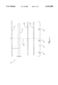
- FIG. 1 is a sectional, schematic view of a flat-panel display with its associated illumination source
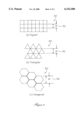
- FIG. 2 is a plan view of three embodiments of collimating lattice geometries
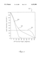
- FIG. 3 is a graph showing the light-collimating ability of each element depicted in FIG. 1;
- FIG. 4 is a schematic representation of a pixel and its neighboring pixels in a tiled, flat-panel display.
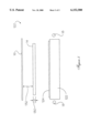
- FIG. 5 is a sectional, schematic view of a flat-panel display, including an optical collimator.
- the invention features an apparatus and a method for constructing a highly collimated light source for use with a seamless, flat-panel display.
- the degree of collimation required to achieve a seamless appearing display with a sharp image may be obtained with an open cell lattice having non-reflecting side walls. Both the lattice dimensions and the position of the lattice relative to the display are chosen so as to provide optimum collimation and illumination.
- Display assembly 10 utilizes a conventional light box 12 in conjunction with the collimating lattice 14 and a tiled, flat-panel display 16.
- a conventional light source for an LCD display would normally consist of three elements: a light box 12 housing one or more fluorescent lamps 18, a diffuser sheet 20, and an optical collimator (brightness enhancing films) 22.
- This invention adds a fourth element: a collimating lattice 14, having thickness H, and displaced distance D from the LCD display 16.
- Lattice 14 is used to produce the highly collimated light needed for use with a tiled, flat-panel display having visually imperceptible seams and a sharp image. Dimensions H and D will be discussed in detail hereinbelow.
- FIG. 2 there are shown plan views of three geometric shapes of collimating lattices suitable for use in practicing the method of the present invention.
- the upper portion of FIG. 2 shows a lattice of square cells 30; the middle portion of FIG. 2 shows a lattice having triangular cells 40; and the lower portion of FIG. 2 shows a lattice formed from hexagonal or honey comb cells 50.
- the lattice cells 30, 40, 50 can be characterized by a typical cell width dimension W, of 3-5 mm, 32, 42, 52, respectively.
- the lattice 30, 40, 50 may be constructed from any material that is thin, such as plastic, paper, aluminum, or other metals.
- the interior surfaces of the cells may be plated, dyed, painted, or treated in any other way known to those of skill in the art, to produce a surface with uniformly minimal specular and diffuse reflectivity across the visible spectrum of light. Instead of surface treatment, the material itself can be non-reflective.
- the wall thickness of the cells, not shown, is minimized to permit as much light as possible to pass through the lattice 30, 40, 50.
- a readily available aluminum honey comb lattice is spray- or dip-painted with a matte black paint.
- FIG. 3 there is shown a graph 60 of the relative collimating efficiencies of various collimating elements of the light source shown in FIG. 1: diffuser 20, optical collimator 22 and lattice collimator 14.
- an ideal diffuser 20 should disperse the light from the lamps 18 forward in all directions, at uniform brightness. Light intensity should be constant at all angles measured with respect to a line 24 normal to the front or rear surface planes of the diffuser 20. Light of this nature is referred to as Lambertian. The light from lamps 18 first passes through diffuser 20 and then passes through an optical collimator or brightness enhancing film 22.
- FIG. 4 there is shown generally at reference number 100, a schematic view of a target display pixel 102 adjacent to a tile edge 104. Neighboring pixels, 106, 108, 108', 110 and 110' are also shown. Light entering the rear of the display (arrow 112) in the target pixel area 102 at off-normal angles beyond the desired cut-off angle exit the display in a neighboring pixel, for example through pixel areas 108 or 108'. Light passing through the display encounters a succession of optical active media: a polarizer, then liquid crystal material, and then another polarizer.
- the viewer is not able to discriminate individual pixels if too much stray light (light beyond the desired cut-off angle) illuminates the rear of the display.
- An image viewed on a display with too much stray light is perceived as out of focus compared to the same image viewed on a display with less stray light.
- an image viewed on a display without excessive stray light is perceived as sharper than an image viewed on a display with excessive stray light.
- Waveguide 122 is made of an optically clear material such as acrylic, glass, or polycarbonate.
- a collimating sheet 124 is bonded to the top of wave guide 122 using an optically transmissive adhesive having a suitable index of refraction such as acrylic adhesive or clear silicone adhesive.
- Collimating sheet 124 typically comprises arrays of Fresnel-type lenses and works on the principle of total internal reflection.
- the light produced by such a light source assembly 18, 122, 124 is collimated, but not sufficiently for a tiled, flat-panel display 16 to appear sharp and seamless.
- the addition of a collimating lattice 14 used in conjunction with this type of light source assembly does provide the necessary degree of collimation.
- the desired collimation angle can be calculated from a consideration of the display pixel geometry and mask geometry within display 16.
- the collimating lattice 14 is selected by choosing a ratio of lattice cell width W 32, 42 or 52 to lattice cell depth H 130, equal to the tangent of the desired collimation or cut-off angle.
- the collimating lattice 14 must be placed a sufficient distance, D 132, behind the display so that the shadow of the cell geometry itself is not imaged (i.e., projected or shadowed) onto display 16.
- a typical tiled display 16 may dictate a collimation angle of 25 degrees off-normal.
- the lattice is then selected with a height H 130 equal to twice the cell width W.
- a larger ratio may also work, but can result in discarding more of the available visible light energy than is necessary.
- the collimating lattice 14 must be placed at a distance of at least D 132 from the display 16 greater than twice the cell height H 130 in order to avoid imaging the lattice 14 by the display 16 in this example.
- the ratio of the lattice cell width W to cell height H 130 is the same as the ratio of the cell height H 130 to lattice-to-display distance D 132. There is no required relationship between the pixel pitch or spacing, not shown, in display 16 and the collimating lattice 14 cell dimensions.
Abstract
Description
Claims (15)
Priority Applications (1)
| Application Number | Priority Date | Filing Date | Title |
|---|---|---|---|
| US09/024,481 US6152580A (en) | 1998-02-17 | 1998-02-17 | Apparatus and method for producing collimated light from an area source |
Applications Claiming Priority (1)
| Application Number | Priority Date | Filing Date | Title |
|---|---|---|---|
| US09/024,481 US6152580A (en) | 1998-02-17 | 1998-02-17 | Apparatus and method for producing collimated light from an area source |
Publications (1)
| Publication Number | Publication Date |
|---|---|
| US6152580A true US6152580A (en) | 2000-11-28 |
Family
ID=21820812
Family Applications (1)
| Application Number | Title | Priority Date | Filing Date |
|---|---|---|---|
| US09/024,481 Expired - Lifetime US6152580A (en) | 1998-02-17 | 1998-02-17 | Apparatus and method for producing collimated light from an area source |
Country Status (1)
| Country | Link |
|---|---|
| US (1) | US6152580A (en) |
Cited By (8)
| Publication number | Priority date | Publication date | Assignee | Title |
|---|---|---|---|---|
| WO2001053883A1 (en) * | 2000-01-21 | 2001-07-26 | Rainbow Displays, Inc. | Construction of large, robust, monolithic and monolithic-like, amlcd displays with wide view angle |
| US6527410B2 (en) * | 2000-02-02 | 2003-03-04 | Fuji Photo Film Co., Ltd. | Illuminating device and liquid-crystal display apparatus |
| US6578985B1 (en) * | 2001-07-18 | 2003-06-17 | Rainbow Displays, Inc. | Back light assembly for use with back-to-back flat-panel displays |
| US20030184703A1 (en) * | 2000-01-21 | 2003-10-02 | Greene Raymond G. | Construction of large, robust, monolithic and monolithic-like, AMLCD displays with wide view angle |
| US20030210535A1 (en) * | 2002-05-09 | 2003-11-13 | Gaides Gary E. | Display device |
| US20060077402A1 (en) * | 2003-04-30 | 2006-04-13 | Ralf Christoph | Co-ordinate-measuring instrument |
| EP1696260A3 (en) * | 2005-02-08 | 2007-04-25 | AEG Gesellschaft für moderne Informationssysteme mbH | Liquid crystal display and liquid crystal display system comprising a plurality of such liquid crystal displays |
| US10216066B2 (en) | 2013-10-24 | 2019-02-26 | Stephen Pilby | Flexible light control grid with collapsible frame |
Citations (11)
| Publication number | Priority date | Publication date | Assignee | Title |
|---|---|---|---|---|
| US2398799A (en) * | 1940-07-19 | 1946-04-23 | Frederick R Miller | Light screen |
| US3413745A (en) * | 1967-04-05 | 1968-12-03 | Tamar Electronics Ind Inc | Blankout sign |
| US4005538A (en) * | 1973-11-23 | 1977-02-01 | Minnesota Mining And Manufacturing Company | Internally illuminated retroreflective signs |
| US4915479A (en) * | 1986-12-17 | 1990-04-10 | U.S. Philips Corporation | Liquid crystal display illumination system |
| US5044734A (en) * | 1988-12-16 | 1991-09-03 | Krone Aktiengesellschaft | Electro-optical flat-design display device, in particular LCD area |
| JPH0422938A (en) * | 1990-05-18 | 1992-01-27 | Sony Corp | Liquid crystal projector device |
| US5128783A (en) * | 1990-01-31 | 1992-07-07 | Ois Optical Imaging Systems, Inc. | Diffusing/collimating lens array for a liquid crystal display |
| JPH0651338A (en) * | 1992-07-29 | 1994-02-25 | Sharp Corp | Liquid crystal display device |
| US5598281A (en) * | 1993-11-19 | 1997-01-28 | Alliedsignal Inc. | Backlight assembly for improved illumination employing tapered optical elements |
| US5661531A (en) * | 1996-01-29 | 1997-08-26 | Rainbow Displays Inc. | Tiled, flat-panel display having invisible seams |
| US5808719A (en) * | 1994-09-02 | 1998-09-15 | Sharp Kabushiki Kaisha | Liquid crystal display apparatus wherein plurality display panels makes display surfaces flush by perming junction panel and producing method thereof |
-
1998
- 1998-02-17 US US09/024,481 patent/US6152580A/en not_active Expired - Lifetime
Patent Citations (11)
| Publication number | Priority date | Publication date | Assignee | Title |
|---|---|---|---|---|
| US2398799A (en) * | 1940-07-19 | 1946-04-23 | Frederick R Miller | Light screen |
| US3413745A (en) * | 1967-04-05 | 1968-12-03 | Tamar Electronics Ind Inc | Blankout sign |
| US4005538A (en) * | 1973-11-23 | 1977-02-01 | Minnesota Mining And Manufacturing Company | Internally illuminated retroreflective signs |
| US4915479A (en) * | 1986-12-17 | 1990-04-10 | U.S. Philips Corporation | Liquid crystal display illumination system |
| US5044734A (en) * | 1988-12-16 | 1991-09-03 | Krone Aktiengesellschaft | Electro-optical flat-design display device, in particular LCD area |
| US5128783A (en) * | 1990-01-31 | 1992-07-07 | Ois Optical Imaging Systems, Inc. | Diffusing/collimating lens array for a liquid crystal display |
| JPH0422938A (en) * | 1990-05-18 | 1992-01-27 | Sony Corp | Liquid crystal projector device |
| JPH0651338A (en) * | 1992-07-29 | 1994-02-25 | Sharp Corp | Liquid crystal display device |
| US5598281A (en) * | 1993-11-19 | 1997-01-28 | Alliedsignal Inc. | Backlight assembly for improved illumination employing tapered optical elements |
| US5808719A (en) * | 1994-09-02 | 1998-09-15 | Sharp Kabushiki Kaisha | Liquid crystal display apparatus wherein plurality display panels makes display surfaces flush by perming junction panel and producing method thereof |
| US5661531A (en) * | 1996-01-29 | 1997-08-26 | Rainbow Displays Inc. | Tiled, flat-panel display having invisible seams |
Non-Patent Citations (2)
| Title |
|---|
| Gerard A. Alphonse and Jeffrey Lubin, "Psychophysical Requirements for Tiled Large Screen Displays", SPIE Journal vol. 1664, pp. 230-240, 1992. |
| Gerard A. Alphonse and Jeffrey Lubin, Psychophysical Requirements for Tiled Large Screen Displays , SPIE Journal vol. 1664, pp. 230 240, 1992. * |
Cited By (15)
| Publication number | Priority date | Publication date | Assignee | Title |
|---|---|---|---|---|
| US20030184703A1 (en) * | 2000-01-21 | 2003-10-02 | Greene Raymond G. | Construction of large, robust, monolithic and monolithic-like, AMLCD displays with wide view angle |
| WO2001053883A1 (en) * | 2000-01-21 | 2001-07-26 | Rainbow Displays, Inc. | Construction of large, robust, monolithic and monolithic-like, amlcd displays with wide view angle |
| US6527410B2 (en) * | 2000-02-02 | 2003-03-04 | Fuji Photo Film Co., Ltd. | Illuminating device and liquid-crystal display apparatus |
| USRE40355E1 (en) | 2001-07-18 | 2008-06-03 | Seiko Epson Corporation | Back light assembly for use with back-to-back flat-panel displays |
| US6578985B1 (en) * | 2001-07-18 | 2003-06-17 | Rainbow Displays, Inc. | Back light assembly for use with back-to-back flat-panel displays |
| USRE42975E1 (en) | 2001-07-18 | 2011-11-29 | Seiko Epson Corporation | Back light assembly for use with back-to-back flat-panel displays |
| USRE43125E1 (en) * | 2001-07-18 | 2012-01-24 | Seiko Epson Corporation | Back light assembly for use with back-to-back flat-panel displays |
| USRE44575E1 (en) | 2001-07-18 | 2013-11-05 | Seiko Epson Corporation | Back light assembly for use with back-to-back flat-panel displays |
| US20030210535A1 (en) * | 2002-05-09 | 2003-11-13 | Gaides Gary E. | Display device |
| WO2003095257A1 (en) * | 2002-05-09 | 2003-11-20 | 3M Innovative Properties Company | Display device |
| US6905219B2 (en) | 2002-05-09 | 2005-06-14 | 3M Innovative Properties Company | Display device |
| US20060077402A1 (en) * | 2003-04-30 | 2006-04-13 | Ralf Christoph | Co-ordinate-measuring instrument |
| US7400412B2 (en) * | 2003-04-30 | 2008-07-15 | Werth Messtechnik Gmbh | Co-ordinate measuring instrument |
| EP1696260A3 (en) * | 2005-02-08 | 2007-04-25 | AEG Gesellschaft für moderne Informationssysteme mbH | Liquid crystal display and liquid crystal display system comprising a plurality of such liquid crystal displays |
| US10216066B2 (en) | 2013-10-24 | 2019-02-26 | Stephen Pilby | Flexible light control grid with collapsible frame |
Similar Documents
| Publication | Publication Date | Title |
|---|---|---|
| JP3123006B2 (en) | Surface light source and liquid crystal display | |
| US5897184A (en) | Reduced-thickness backlighter for autostereoscopic display and display using the backlighter | |
| US5608550A (en) | Front-lit liquid crystal display having brightness enhancing film with microridges which directs light through the display to a reflector | |
| EP0271956B1 (en) | A liquid crystal display illumination system | |
| JP3613065B2 (en) | Liquid crystal display | |
| US7746570B2 (en) | Fresnel optical element and projection display apparatus | |
| US7595934B2 (en) | Integrated sub-assembly having a light collimating or transflecting device | |
| DE69728754T2 (en) | REAR LIGHTING DEVICE OF A LIQUID CRYSTAL DISPLAY DEVICE | |
| US6995907B2 (en) | Diffusion sheet for use in transmission-type screen and transmission-type screen | |
| US6697042B1 (en) | Backlight assembly for collimated illumination | |
| JP4075000B2 (en) | Surface lighting device | |
| US20050259198A1 (en) | Light collimating device | |
| EP0511721A2 (en) | Front projection screen with reflected light concentrating lens array | |
| CN109765725B (en) | Collimation film, collimation backlight module, display module and display device | |
| JP2007148297A (en) | Optical sheet for backlight, backlight and display device | |
| US20060007536A1 (en) | Total internal reflection fresnel-lens and devices | |
| JP2005292679A (en) | Micromirror screen | |
| US9772550B2 (en) | Apparatus, system and method for mitigating contrast artifacts at an overlap region of a projected image | |
| US6152580A (en) | Apparatus and method for producing collimated light from an area source | |
| DE69929622T2 (en) | PROJECTION SYSTEM | |
| JP2009140905A (en) | Light guide plate and backlight | |
| US7233440B2 (en) | Image display screen having wide vertical and horizontal viewing angles and projection television including the same | |
| JP4218294B2 (en) | Display device | |
| CN103017007A (en) | Optical adhesion film and backlight module and liquid crystal display with same | |
| KR950033601A (en) | Lighting device and liquid crystal display device using the same |
Legal Events
| Date | Code | Title | Description |
|---|---|---|---|
| STCF | Information on status: patent grant |
Free format text: PATENTED CASE |
|
| FPAY | Fee payment |
Year of fee payment: 4 |
|
| FEPP | Fee payment procedure |
Free format text: PAT HOLDER NO LONGER CLAIMS SMALL ENTITY STATUS, ENTITY STATUS SET TO UNDISCOUNTED (ORIGINAL EVENT CODE: STOL); ENTITY STATUS OF PATENT OWNER: LARGE ENTITY |
|
| AS | Assignment |
Owner name: TRANSPACIFIC IP LTD., TAIWAN Free format text: ASSIGNMENT OF ASSIGNORS INTEREST;ASSIGNOR:RAINBOW DISPLAYS, INC.;REEL/FRAME:018606/0822 Effective date: 20060816 |
|
| AS | Assignment |
Owner name: TRANSPACIFIC EXCHANGE, LLC, DELAWARE Free format text: ASSIGNMENT OF ASSIGNORS INTEREST;ASSIGNOR:TRANSPACIFIC IP LTD.;REEL/FRAME:019297/0982 Effective date: 20070427 |
|
| FPAY | Fee payment |
Year of fee payment: 8 |
|
| FPAY | Fee payment |
Year of fee payment: 12 |
|
| AS | Assignment |
Owner name: HANGER SOLUTIONS, LLC, GEORGIA Free format text: ASSIGNMENT OF ASSIGNORS INTEREST;ASSIGNOR:INTELLECTUAL VENTURES ASSETS 161 LLC;REEL/FRAME:052159/0509 Effective date: 20191206 |
|
| AS | Assignment |
Owner name: INTELLECTUAL VENTURES ASSETS 161 LLC, DELAWARE Free format text: ASSIGNMENT OF ASSIGNORS INTEREST;ASSIGNOR:TRANSPACIFIC EXCHANGE, LLC;REEL/FRAME:051853/0162 Effective date: 20191126 |