US6152660A - Drilling tool for bores in solid material - Google Patents
Drilling tool for bores in solid material Download PDFInfo
- Publication number
- US6152660A US6152660A US09/218,810 US21881098A US6152660A US 6152660 A US6152660 A US 6152660A US 21881098 A US21881098 A US 21881098A US 6152660 A US6152660 A US 6152660A
- Authority
- US
- United States
- Prior art keywords
- drilling tool
- cutter
- coating
- coated
- tool according
- Prior art date
- Legal status (The legal status is an assumption and is not a legal conclusion. Google has not performed a legal analysis and makes no representation as to the accuracy of the status listed.)
- Expired - Fee Related
Links
Images
Classifications
-
- B—PERFORMING OPERATIONS; TRANSPORTING
- B23—MACHINE TOOLS; METAL-WORKING NOT OTHERWISE PROVIDED FOR
- B23B—TURNING; BORING
- B23B51/00—Tools for drilling machines
-
- B—PERFORMING OPERATIONS; TRANSPORTING
- B23—MACHINE TOOLS; METAL-WORKING NOT OTHERWISE PROVIDED FOR
- B23B—TURNING; BORING
- B23B2228/00—Properties of materials of tools or workpieces, materials of tools or workpieces applied in a specific manner
- B23B2228/10—Coatings
- B23B2228/105—Coatings with specified thickness
-
- Y—GENERAL TAGGING OF NEW TECHNOLOGICAL DEVELOPMENTS; GENERAL TAGGING OF CROSS-SECTIONAL TECHNOLOGIES SPANNING OVER SEVERAL SECTIONS OF THE IPC; TECHNICAL SUBJECTS COVERED BY FORMER USPC CROSS-REFERENCE ART COLLECTIONS [XRACs] AND DIGESTS
- Y10—TECHNICAL SUBJECTS COVERED BY FORMER USPC
- Y10T—TECHNICAL SUBJECTS COVERED BY FORMER US CLASSIFICATION
- Y10T407/00—Cutters, for shaping
- Y10T407/26—Cutters, for shaping comprising cutting edge bonded to tool shank
-
- Y—GENERAL TAGGING OF NEW TECHNOLOGICAL DEVELOPMENTS; GENERAL TAGGING OF CROSS-SECTIONAL TECHNOLOGIES SPANNING OVER SEVERAL SECTIONS OF THE IPC; TECHNICAL SUBJECTS COVERED BY FORMER USPC CROSS-REFERENCE ART COLLECTIONS [XRACs] AND DIGESTS
- Y10—TECHNICAL SUBJECTS COVERED BY FORMER USPC
- Y10T—TECHNICAL SUBJECTS COVERED BY FORMER US CLASSIFICATION
- Y10T408/00—Cutting by use of rotating axially moving tool
- Y10T408/78—Tool of specific diverse material
Definitions
- the invention relates to a drilling tool for bores in solid material and, more particularly, to a drilling tool with a drill shaft and cutting devices at the end of the drilling tool.
- Drilling tools which have a drill shaft with which the drilling tool can be clamped in a suitable seating, and adjoining which in the axial direction is a working region of the tool.
- the following varieties of cutting devices are fastened, either releasably, e.g. screwed or clamped, or unreleasably, e.g., adhered or soldered in suitable seatings:
- At least one cutter which is arranged so that the cutting edge extends from the periphery of the diameter to be produced to at least the center of the diameter to be produced or up to a cross cutter.
- each cutting edge covers a given region of the diameter to be produced.
- the cutting device is embodied as an interchangeable cutter head, in which all of the cutter geometry is machined from one cutting material blank.
- the cutting device is embodied as an interchangeable cutter head, in which only the immediate cutting region consists of the desired cutting material, e.g., brazed-in cutters.
- the cutters are distributed radially at the periphery of the tool, and the angular peripheral distances must not be equally large. If the drilling tool has at least three cutters, then a respective two or more cutters can be located in the same radial position, but at different diameter positions.
- Adjoined to the cutter receiving region in all the stated variants is an axially directed tool shank having at least one recess which serves to transport out of the bore the chips which arise during machining.
- cemented carbide made by powder metallurgy.
- materials are understood by "cemented carbide” whose hard phase substantially consists of tungsten carbide (WC), but also of other carbide formers.
- the cemented carbide consisting substantially of tungsten carbide can be uncoated or can be additionally coated with a hard material.
- the productivity of drilling processes is substantially determined by the features of cutting speed and forward feed, wear behavior and machining quality, and these furthermore depend directly on the properties of the cutting materials used.
- the invention has as its object to markedly improve drilling machining in solid material.
- a drilling tool with at least one cutter of a coated cermet cutting material, preferably with a coating of hard material.
- the cutting material cermet has a high elevated temperature hardness and a high oxidation resistance in comparison with cemented carbide. These properties make possible markedly higher machining speeds than with cemented carbide, in fine machining, for example, boring, reaming, fine turning, finishing milling or the like. In reaming, for example, cutting speeds which are higher by a factor of about 4 are possible with cermet as the cutting material, with a simultaneous improvement of the machining quality and wear resistance. Of course, cermet also has a low bending strength and fracture toughness in comparison with hard metal. These features do not have a great effect in the fine machining of boreholes.
- the typical chip removal cross sections with a cutting depth of about 0.1-0.3 mm are comparatively small here, and the resulting chip removal forces are thus small.
- the chip removal cross sections are markedly greater.
- the chip removal width is about 5 mm, for example, for a solid drill with a diameter of 20 mm with two radially arranged indexable inserts.
- Correspondingly large chip removal forces result from this very large chip removal cross section, and have to be taken up by the cutter. Cermet does not provide the necessary bending strength and fracture toughness for this.
- Coating of the cermet results in a portion of the mechanical load on the cermet being taken up by the coating.
- the load on the cermet is thereby substantially reduced.
- the advantages of the cermet are still in effect. Since cermet is a heat insulator in comparison with hard metal, a larger portion of the chip formation heat remains in the chip which flies off. The cutter thus becomes less hot.
- markedly higher chip removal temperatures can be attained in connection with the higher elevated temperature hardness of the cermet, and this is tantamount to higher machining speeds.
- a coating thickness of less than 50 ⁇ m is advantageously provided for the coating of the cutter. If the drilling tool is provided with at least two spatially separated mountings for mounting the cutter device, a mixed mounting can also be effected. This means that only a portion of the cutter consists of a coated cermet cutting material.
- the coating is a layer of hard material, which has at least titanium and nitrogen as components.
- the coatings can contain components such as, for example, chromium, boron or zirconium and nitrogen, e.g., chromium nitride or zirconium nitride.
- the cermet cutter plate, before coating is mechanically machined on its flank, e.g., by grinding and/or irradiating, and on its tool face either remains unprocessed or is mechanically processed, e.g., by brushing and/or irradiation.
- the mechanically processed flanks and tool faces enable the frictional processes and hence the heat development on chip formation to be reduced, and hence increase the possible machining data.
- possible failure points in the surface such as cracks, remaining sinter residues, and particles which are adhering relatively loosely, can be removed by the mechanical processing.
- the cermet cutter plate produced by sintering technology can be precisely formed such that a coating of the cermet cutter plate can be effected even without mechanical pretreatment, e.g. by grinding, of the flank.
- a mechanical pretreatment of the tool face is also possible here.
- An increase in the stability under load of the cermet cutter plate can be attained by the mechanical processing of the flank and of the tool face, since a better coating bond and thus a better coating adhesion can be set by the smoothed surface.
- the quality of the smoothed surfaces can advantageously be set by the use data of the respective process which is used, for example, grinding means, grinding speed, feed motion, duration of feed or smoothing, smoothing speed and smoothing material.
- the coated cermet cutter plate is mechanically after-treated, e.g., by brushing, irradiation, or polishing.
- the surface quality of the coated flank and chip can be further improved by this after-treatment, and the cutting data for machining are further improved.
- the coatings can be effected both as a monolayer coating and as a multilayer coating.
- the coatings can be deposited on the cermet cutting material by either CVD or PVD processes and their variants.
- the uncoated cermet cutter plate is thermally and/or chemically pretreated for better coating adhesion, and/or that the coated cermet cutter plate is thermally and/or chemically after-treated.
- the cermet cutter plate after the coating can also have its surface mechanically after-treated, e.g., by brushing and polishing.
- the cutting edge of the cermet cutter plate which is formed by the tool face and by the flank, can furthermore be provided with a radius smaller than about 50 ⁇ m (e.g., by brushing), the precision of the radius being predetermined by the process used. An increase in the stability of the cutting edge is attained by this rounding of the edge.
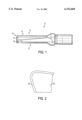
- FIG. 1 shows a schematic side view of a drilling tool for bores in solid material
- FIG. 2 shows a greatly enlarged cross section of a cutter.
- FIG. 1 shows a side view of a drilling tool 11.
- a drill shaft 12 has two axially-extending recesses 13, 14 which are mutually diametrically opposite and which serve for the removal of drill chips.
- indexable inserts 21, 22 are provided in respective seatings at the end 16 of the drilling tool.
- This drilling tool shown in FIG. 1 is only by way of example. There can be provided as a drilling tool each further alternative in which several indexable inserts are used, or else individual cutters are brazed to, or integrally connected with, the drill.
- FIG. 2 shows a greatly enlarged cross section of a cutter in greatly simplified form.
- a cutter base body 24 has a coating 26 which, for example, comprises less than 50 ⁇ m.
- the coating 26 comprises at least the components zirconium, boron or chromium and nitrogen.
- the coating 26 can be constituted as a monolayer or a multilayer.
- the coating 26 is provided according to FIG. 2, by way of example, as a monolayer.
- Cermet is provided as the material for the cutter base body 24. This material, in combination with the coating 26 according to the invention, advantageously has a high wear resistance, which leads to an improvement of the machining quality and an increase of the surface quality in bores.
Abstract
A drilling tool for boreholes in solid material, with a drill shaft with at least one cutter arranged at the end of the drilling tool and at least one recess which extends in the axial direction from the end of the drill tool, to conduct chips from the borehole. At least one of the cutters is made of a coated cermet cutting material.
Description
Not applicable.
Not applicable.
Field of the Invention
The invention relates to a drilling tool for bores in solid material and, more particularly, to a drilling tool with a drill shaft and cutting devices at the end of the drilling tool.
Drilling tools are known which have a drill shaft with which the drilling tool can be clamped in a suitable seating, and adjoining which in the axial direction is a working region of the tool. In the region of an end face of the tool, the following varieties of cutting devices are fastened, either releasably, e.g. screwed or clamped, or unreleasably, e.g., adhered or soldered in suitable seatings:
a cutter which is substantially symmetrical with respect to the drill axis,
at least one cutter which is arranged so that the cutting edge extends from the periphery of the diameter to be produced to at least the center of the diameter to be produced or up to a cross cutter.
two or more cutters, which can have different geometries, and which are arranged such that each cutting edge covers a given region of the diameter to be produced.
one of the previously stated arrangements, in which the cutting device is embodied as an interchangeable cutter head, in which all of the cutter geometry is machined from one cutting material blank.
one of the previously stated arrangements, in which the cutting device is embodied as an interchangeable cutter head, in which only the immediate cutting region consists of the desired cutting material, e.g., brazed-in cutters.
When the drilling tool has at least two cutters, then the cutters are distributed radially at the periphery of the tool, and the angular peripheral distances must not be equally large. If the drilling tool has at least three cutters, then a respective two or more cutters can be located in the same radial position, but at different diameter positions.
Adjoined to the cutter receiving region in all the stated variants is an axially directed tool shank having at least one recess which serves to transport out of the bore the chips which arise during machining.
These described drilling devices are produced from a cemented carbide made by powder metallurgy. In chip-producing manufacture, however, materials are understood by "cemented carbide" whose hard phase substantially consists of tungsten carbide (WC), but also of other carbide formers. The cemented carbide consisting substantially of tungsten carbide can be uncoated or can be additionally coated with a hard material.
The productivity of drilling processes is substantially determined by the features of cutting speed and forward feed, wear behavior and machining quality, and these furthermore depend directly on the properties of the cutting materials used.
The invention has as its object to markedly improve drilling machining in solid material.
This object is attained by a drilling tool with at least one cutter of a coated cermet cutting material, preferably with a coating of hard material.
The cutting material cermet has a high elevated temperature hardness and a high oxidation resistance in comparison with cemented carbide. These properties make possible markedly higher machining speeds than with cemented carbide, in fine machining, for example, boring, reaming, fine turning, finishing milling or the like. In reaming, for example, cutting speeds which are higher by a factor of about 4 are possible with cermet as the cutting material, with a simultaneous improvement of the machining quality and wear resistance. Of course, cermet also has a low bending strength and fracture toughness in comparison with hard metal. These features do not have a great effect in the fine machining of boreholes. The typical chip removal cross sections with a cutting depth of about 0.1-0.3 mm are comparatively small here, and the resulting chip removal forces are thus small. For drilling in solid material (rough machining), on the other hand, the chip removal cross sections are markedly greater. Thus the chip removal width is about 5 mm, for example, for a solid drill with a diameter of 20 mm with two radially arranged indexable inserts. Correspondingly large chip removal forces result from this very large chip removal cross section, and have to be taken up by the cutter. Cermet does not provide the necessary bending strength and fracture toughness for this.
Coating of the cermet results in a portion of the mechanical load on the cermet being taken up by the coating. The load on the cermet is thereby substantially reduced. However, because of the small coating thickness, the advantages of the cermet are still in effect. Since cermet is a heat insulator in comparison with hard metal, a larger portion of the chip formation heat remains in the chip which flies off. The cutter thus becomes less hot. Thus markedly higher chip removal temperatures can be attained in connection with the higher elevated temperature hardness of the cermet, and this is tantamount to higher machining speeds.
A coating thickness of less than 50 μm is advantageously provided for the coating of the cutter. If the drilling tool is provided with at least two spatially separated mountings for mounting the cutter device, a mixed mounting can also be effected. This means that only a portion of the cutter consists of a coated cermet cutting material.
In an advantageous embodiment of the invention, it is provided that the coating is a layer of hard material, which has at least titanium and nitrogen as components. Furthermore, the coatings can contain components such as, for example, chromium, boron or zirconium and nitrogen, e.g., chromium nitride or zirconium nitride.
According to a further advantageous embodiment of the invention, it is provided that the cermet cutter plate, before coating, is mechanically machined on its flank, e.g., by grinding and/or irradiating, and on its tool face either remains unprocessed or is mechanically processed, e.g., by brushing and/or irradiation. The mechanically processed flanks and tool faces enable the frictional processes and hence the heat development on chip formation to be reduced, and hence increase the possible machining data. In addition, possible failure points in the surface, such as cracks, remaining sinter residues, and particles which are adhering relatively loosely, can be removed by the mechanical processing.
Alternatively, it can likewise be provided that the cermet cutter plate produced by sintering technology can be precisely formed such that a coating of the cermet cutter plate can be effected even without mechanical pretreatment, e.g. by grinding, of the flank. A mechanical pretreatment of the tool face is also possible here.
An increase in the stability under load of the cermet cutter plate can be attained by the mechanical processing of the flank and of the tool face, since a better coating bond and thus a better coating adhesion can be set by the smoothed surface. The quality of the smoothed surfaces can advantageously be set by the use data of the respective process which is used, for example, grinding means, grinding speed, feed motion, duration of feed or smoothing, smoothing speed and smoothing material.
Furthermore it is advantageously provided that the coated cermet cutter plate is mechanically after-treated, e.g., by brushing, irradiation, or polishing. The surface quality of the coated flank and chip can be further improved by this after-treatment, and the cutting data for machining are further improved.
According to a further advantageous embodiment of the invention, the coatings can be effected both as a monolayer coating and as a multilayer coating.
According to a further advantageous embodiment of the invention, it is provided that the coatings can be deposited on the cermet cutting material by either CVD or PVD processes and their variants.
In a further advantageous embodiment of the invention, it is provided that the uncoated cermet cutter plate is thermally and/or chemically pretreated for better coating adhesion, and/or that the coated cermet cutter plate is thermally and/or chemically after-treated. Furthermore, the cermet cutter plate after the coating can also have its surface mechanically after-treated, e.g., by brushing and polishing.
Advantageously the cutting edge of the cermet cutter plate, which is formed by the tool face and by the flank, can furthermore be provided with a radius smaller than about 50 μm (e.g., by brushing), the precision of the radius being predetermined by the process used. An increase in the stability of the cutting edge is attained by this rounding of the edge.
A preferred embodiment is shown in the following drawings, in which:
FIG. 1 shows a schematic side view of a drilling tool for bores in solid material, and
FIG. 2 shows a greatly enlarged cross section of a cutter.
FIG. 1 shows a side view of a drilling tool 11. A drill shaft 12 has two axially-extending recesses 13, 14 which are mutually diametrically opposite and which serve for the removal of drill chips. indexable inserts 21, 22 are provided in respective seatings at the end 16 of the drilling tool.
This drilling tool shown in FIG. 1 is only by way of example. There can be provided as a drilling tool each further alternative in which several indexable inserts are used, or else individual cutters are brazed to, or integrally connected with, the drill.
FIG. 2 shows a greatly enlarged cross section of a cutter in greatly simplified form. A cutter base body 24 has a coating 26 which, for example, comprises less than 50 μm. The coating 26 comprises at least the components zirconium, boron or chromium and nitrogen. The coating 26 can be constituted as a monolayer or a multilayer. The coating 26 is provided according to FIG. 2, by way of example, as a monolayer. Cermet is provided as the material for the cutter base body 24. This material, in combination with the coating 26 according to the invention, advantageously has a high wear resistance, which leads to an improvement of the machining quality and an increase of the surface quality in bores.
Claims (13)
1. A drilling tool for boreholes in solid material, comprising:
a drill shaft,
at least one cutter arranged at the end of the drilling tool, and
at least one recess which extends in an axial direction from said end of said drilling tool to conduct chips from the boreholes,
in which said at least one cutter is comprised of a coated cermet cutting material and in which said cutter has a flank and a tool face, with a radius of less than 50 μm between said flank and said tool face.
2. The drilling tool according to claim 1, in which the coating of the coated cermet cutting material contains at least one of titanium and nitrogen.
3. The drilling tool according to claim 1, in which the coating of the coated cermet cutting material contains nitrogen and one of zirconium, boron, or chromium.
4. The drilling tool according to claim 1, in which said cutter is a sintered cutter plate with an unprocessed flank, an unprocessed tool face.
5. The drilling tool according to claim 1, in which said cutter is a sintered plate with a pre-coated, processed flank.
6. The drilling tool according to claim 1, in which said cutter is a sintered plate with a post-coated, processed flank.
7. The drilling tool according to claim 1, in which said cutter is a sintered plate with a pre-coated, processed tool face.
8. The drilling tool according to claim 1, in which said cutter is a sintered plate with a post-coated, processed tool face.
9. The drilling tool according to claim 1, in which the coating of said coated cermet cutting material comprises a layer of hard material.
10. The drilling tool according to claim 1, in which said layer of hard material has a layer thickness of less than 50 μm.
11. The drilling tool according to claim 1, in which the coating of said coated cutting material is formed as one of a monolayer or multilayer coating.
12. The drilling tool according to claim 1, in which said coating is a cermet coating.
13. A method of producing boreholes in solid material comprising using cutters comprised of coated cermet cutting material for a drilling tool with a drill shaft, with at least one said cutter arranged at the end of the drilling tool and at least one chip-conducting axial recess, providing said cutter with a flank and a tool face, with a radius of less than 50 μm between said flank and said tool face.
Applications Claiming Priority (2)
| Application Number | Priority Date | Filing Date | Title |
|---|---|---|---|
| DE19757242A DE19757242A1 (en) | 1997-12-22 | 1997-12-22 | Drilling tool for drilling in solid material |
| DE19757242 | 1997-12-22 |
Publications (1)
| Publication Number | Publication Date |
|---|---|
| US6152660A true US6152660A (en) | 2000-11-28 |
Family
ID=7853002
Family Applications (1)
| Application Number | Title | Priority Date | Filing Date |
|---|---|---|---|
| US09/218,810 Expired - Fee Related US6152660A (en) | 1997-12-22 | 1998-12-22 | Drilling tool for bores in solid material |
Country Status (3)
| Country | Link |
|---|---|
| US (1) | US6152660A (en) |
| EP (1) | EP0924014A1 (en) |
| DE (1) | DE19757242A1 (en) |
Cited By (5)
| Publication number | Priority date | Publication date | Assignee | Title |
|---|---|---|---|---|
| US6402605B1 (en) * | 1999-12-29 | 2002-06-11 | Hecaeus Quarzglas Gmbh & Co. Kg | Drilling device for brittle materials |
| US6660329B2 (en) | 2001-09-05 | 2003-12-09 | Kennametal Inc. | Method for making diamond coated cutting tool |
| US20040182216A1 (en) * | 2002-07-31 | 2004-09-23 | Electrolux Professional Outdoor Products, Inc. | Coating for a chainsaw chain |
| US8052765B2 (en) | 2007-04-03 | 2011-11-08 | Cho H Sam | Contoured PCD and PCBN for twist drill tips and end mills and methods of forming the same |
| US9468980B2 (en) | 2007-04-03 | 2016-10-18 | H. Sam Cho | Contoured PCD and PCBN segments for cutting tools containing such segments |
Families Citing this family (2)
| Publication number | Priority date | Publication date | Assignee | Title |
|---|---|---|---|---|
| DE10337985B4 (en) * | 2003-08-14 | 2005-07-28 | Mk Werkzeug-Service Manfred Krystek E.K. | Weld point drill |
| ITBS20070157A1 (en) | 2007-10-16 | 2009-04-17 | Noma Di Belleri F Lli S N C | TOOL BODY OR CUTTING TOOL WITH ZIRCONIUM-BASED SURFACE TREATMENT |
Citations (17)
| Publication number | Priority date | Publication date | Assignee | Title |
|---|---|---|---|---|
| GB2085769A (en) * | 1980-10-06 | 1982-05-06 | Nippon Oils & Fats Co Ltd | High hardness cutting tool |
| US4704055A (en) * | 1983-02-08 | 1987-11-03 | Gottlieb Guhring | Drill with cooling channel |
| US4818153A (en) * | 1985-11-07 | 1989-04-04 | Santrade Limited | Cutting insert having means for detecting wear |
| US5154550A (en) * | 1990-02-20 | 1992-10-13 | Sumitomo Electric Industries, Ltd. | Throw-away tipped drill bit |
| US5186739A (en) * | 1989-02-22 | 1993-02-16 | Sumitomo Electric Industries, Ltd. | Cermet alloy containing nitrogen |
| JPH0592304A (en) * | 1991-05-21 | 1993-04-16 | Nachi Fujikoshi Corp | Multilayer coating tool |
| US5228812A (en) * | 1989-12-25 | 1993-07-20 | Sumitomo Electric Industries, Ltd. | Throw-away tipped drill |
| US5580196A (en) * | 1991-08-08 | 1996-12-03 | Habit Diamond Limited | Wear resistant tools |
| US5599145A (en) * | 1992-11-23 | 1997-02-04 | Joerg Guehring | Drill with interchangeable cutting insert |
| US5641251A (en) * | 1994-07-14 | 1997-06-24 | Cerasiv Gmbh Innovatives Keramik-Engineering | All-ceramic drill bit |
| US5716170A (en) * | 1996-05-15 | 1998-02-10 | Kennametal Inc. | Diamond coated cutting member and method of making the same |
| US5788431A (en) * | 1995-06-23 | 1998-08-04 | August Beck Gmbh & Co. | Drilling tool |
| US5853268A (en) * | 1995-04-18 | 1998-12-29 | Saint-Gobain/Norton Industrial Ceramics Corporation | Method of manufacturing diamond-coated cutting tool inserts and products resulting therefrom |
| US5855458A (en) * | 1993-03-09 | 1999-01-05 | Hydra Tools International Plc | Rotary cutter |
| US5865571A (en) * | 1997-06-17 | 1999-02-02 | Norton Company | Non-metallic body cutting tools |
| US5882152A (en) * | 1997-06-09 | 1999-03-16 | Janitzki; Bernhard M. | Multi-bit drill |
| US5909985A (en) * | 1996-05-08 | 1999-06-08 | Fuji Seiko Limited | Drill having plate-like cutter member fixed at proximal end to shank and having cutting edge at distal portion |
Family Cites Families (7)
| Publication number | Priority date | Publication date | Assignee | Title |
|---|---|---|---|---|
| JPS59219122A (en) * | 1983-05-27 | 1984-12-10 | Sumitomo Electric Ind Ltd | Covered sintered hard alloy tool and manufacturing method thereof |
| JPS62192576A (en) * | 1986-02-17 | 1987-08-24 | Daijietsuto Kogyo Kk | Coated hard alloy |
| JPS62278267A (en) * | 1986-05-24 | 1987-12-03 | Hitachi Tool Eng Ltd | Surface-coated ticn cermet |
| JPS62290870A (en) * | 1987-04-17 | 1987-12-17 | Sumitomo Electric Ind Ltd | Manufacture of coated hard member |
| US5075181A (en) * | 1989-05-05 | 1991-12-24 | Kennametal Inc. | High hardness/high compressive stress multilayer coated tool |
| JP2793773B2 (en) * | 1994-05-13 | 1998-09-03 | 神鋼コベルコツール株式会社 | Hard coating, hard coating tool and hard coating member excellent in wear resistance |
| DE19608185A1 (en) * | 1996-03-04 | 1997-09-11 | Guehring Joerg Dr | Multi-cutter drill working from solid in all directions |
-
1997
- 1997-12-22 DE DE19757242A patent/DE19757242A1/en not_active Withdrawn
-
1998
- 1998-12-17 EP EP98123961A patent/EP0924014A1/en not_active Withdrawn
- 1998-12-22 US US09/218,810 patent/US6152660A/en not_active Expired - Fee Related
Patent Citations (17)
| Publication number | Priority date | Publication date | Assignee | Title |
|---|---|---|---|---|
| GB2085769A (en) * | 1980-10-06 | 1982-05-06 | Nippon Oils & Fats Co Ltd | High hardness cutting tool |
| US4704055A (en) * | 1983-02-08 | 1987-11-03 | Gottlieb Guhring | Drill with cooling channel |
| US4818153A (en) * | 1985-11-07 | 1989-04-04 | Santrade Limited | Cutting insert having means for detecting wear |
| US5186739A (en) * | 1989-02-22 | 1993-02-16 | Sumitomo Electric Industries, Ltd. | Cermet alloy containing nitrogen |
| US5228812A (en) * | 1989-12-25 | 1993-07-20 | Sumitomo Electric Industries, Ltd. | Throw-away tipped drill |
| US5154550A (en) * | 1990-02-20 | 1992-10-13 | Sumitomo Electric Industries, Ltd. | Throw-away tipped drill bit |
| JPH0592304A (en) * | 1991-05-21 | 1993-04-16 | Nachi Fujikoshi Corp | Multilayer coating tool |
| US5580196A (en) * | 1991-08-08 | 1996-12-03 | Habit Diamond Limited | Wear resistant tools |
| US5599145A (en) * | 1992-11-23 | 1997-02-04 | Joerg Guehring | Drill with interchangeable cutting insert |
| US5855458A (en) * | 1993-03-09 | 1999-01-05 | Hydra Tools International Plc | Rotary cutter |
| US5641251A (en) * | 1994-07-14 | 1997-06-24 | Cerasiv Gmbh Innovatives Keramik-Engineering | All-ceramic drill bit |
| US5853268A (en) * | 1995-04-18 | 1998-12-29 | Saint-Gobain/Norton Industrial Ceramics Corporation | Method of manufacturing diamond-coated cutting tool inserts and products resulting therefrom |
| US5788431A (en) * | 1995-06-23 | 1998-08-04 | August Beck Gmbh & Co. | Drilling tool |
| US5909985A (en) * | 1996-05-08 | 1999-06-08 | Fuji Seiko Limited | Drill having plate-like cutter member fixed at proximal end to shank and having cutting edge at distal portion |
| US5716170A (en) * | 1996-05-15 | 1998-02-10 | Kennametal Inc. | Diamond coated cutting member and method of making the same |
| US5882152A (en) * | 1997-06-09 | 1999-03-16 | Janitzki; Bernhard M. | Multi-bit drill |
| US5865571A (en) * | 1997-06-17 | 1999-02-02 | Norton Company | Non-metallic body cutting tools |
Cited By (7)
| Publication number | Priority date | Publication date | Assignee | Title |
|---|---|---|---|---|
| US6402605B1 (en) * | 1999-12-29 | 2002-06-11 | Hecaeus Quarzglas Gmbh & Co. Kg | Drilling device for brittle materials |
| US6660329B2 (en) | 2001-09-05 | 2003-12-09 | Kennametal Inc. | Method for making diamond coated cutting tool |
| US20040028892A1 (en) * | 2001-09-05 | 2004-02-12 | Yixiong Liu | Diamond coated cutting tool and method for making the same |
| US6890655B2 (en) | 2001-09-05 | 2005-05-10 | Kennametal Inc. | Diamond coated cutting tool and method for making the same |
| US20040182216A1 (en) * | 2002-07-31 | 2004-09-23 | Electrolux Professional Outdoor Products, Inc. | Coating for a chainsaw chain |
| US8052765B2 (en) | 2007-04-03 | 2011-11-08 | Cho H Sam | Contoured PCD and PCBN for twist drill tips and end mills and methods of forming the same |
| US9468980B2 (en) | 2007-04-03 | 2016-10-18 | H. Sam Cho | Contoured PCD and PCBN segments for cutting tools containing such segments |
Also Published As
| Publication number | Publication date |
|---|---|
| EP0924014A1 (en) | 1999-06-23 |
| DE19757242A1 (en) | 1999-07-01 |
Similar Documents
| Publication | Publication Date | Title |
|---|---|---|
| EP1512477B1 (en) | Support for longhole drill | |
| US5154550A (en) | Throw-away tipped drill bit | |
| US20040234349A1 (en) | Throw-away tip | |
| EP1624988B9 (en) | Cutting tool inserts and methods to manufacture | |
| US6688817B2 (en) | Drill for drilling, a method for making a drill for drilling, and a cutting tool | |
| US20080206001A1 (en) | Cutting tool | |
| US20030175085A1 (en) | Rotary cutting tool | |
| EP1609551A1 (en) | Support pads for drill heads | |
| CA2760600A1 (en) | Superhard insert | |
| US6508150B1 (en) | Reversible cutting tip, method for producing such cutting tip, tool provided with such cutting tips, and method for cutting a workpiece by using such cutting tip or a tool provided with such cutting tip | |
| US6152660A (en) | Drilling tool for bores in solid material | |
| JPH0373210A (en) | High hardness cutting tool and manufacture and use thereof | |
| US20100215448A1 (en) | Method of machining a substrate | |
| RU2475338C2 (en) | Machining tool component | |
| EP0571352A2 (en) | Method of machining composites | |
| KR102316725B1 (en) | End mill Having Cutting Tooth Made of Polycrystalline Diamond | |
| JP7045460B2 (en) | Manufacturing method of cutting tools and cutting products | |
| JP2000158220A (en) | Throwaway drill and shank thereof | |
| JP6825854B2 (en) | Manufacturing method of cutting tools and cutting products | |
| JP2000190108A (en) | Polycrystalline hard sintered body cutting tool | |
| EP4194127A1 (en) | Method for producing a drill tool cutting section and such a drill tool cutting section | |
| JPH04217414A (en) | Throw away drill | |
| KR20240036820A (en) | Burnishing drill having joining structure of guide pad tip | |
| CN115515740A (en) | Drill and method for manufacturing cut product | |
| Brookes | Setting the scene for 2012's tooling shows |
Legal Events
| Date | Code | Title | Description |
|---|---|---|---|
| AS | Assignment |
Owner name: AUGUST BECK GMBH & CO., GERMANY Free format text: ASSIGNMENT OF ASSIGNORS INTEREST;ASSIGNOR:PAPAJEWSKI, JORG;REEL/FRAME:010016/0693 Effective date: 19990205 |
|
| FPAY | Fee payment |
Year of fee payment: 4 |
|
| REMI | Maintenance fee reminder mailed | ||
| LAPS | Lapse for failure to pay maintenance fees | ||
| STCH | Information on status: patent discontinuation |
Free format text: PATENT EXPIRED DUE TO NONPAYMENT OF MAINTENANCE FEES UNDER 37 CFR 1.362 |
|
| FP | Lapsed due to failure to pay maintenance fee |
Effective date: 20081128 |