US6155743A - Anchoring fixture for holding a musical instrument - Google Patents
Anchoring fixture for holding a musical instrument Download PDFInfo
- Publication number
- US6155743A US6155743A US09/208,016 US20801698A US6155743A US 6155743 A US6155743 A US 6155743A US 20801698 A US20801698 A US 20801698A US 6155743 A US6155743 A US 6155743A
- Authority
- US
- United States
- Prior art keywords
- hole
- piece
- wall
- platform
- musical instrument
- Prior art date
- Legal status (The legal status is an assumption and is not a legal conclusion. Google has not performed a legal analysis and makes no representation as to the accuracy of the status listed.)
- Expired - Lifetime
Links
- 238000004873 anchoring Methods 0.000 title claims abstract description 33
- 230000002708 enhancing effect Effects 0.000 abstract description 7
- 239000007769 metal material Substances 0.000 description 3
- 238000003780 insertion Methods 0.000 description 2
- 230000037431 insertion Effects 0.000 description 2
- 230000001105 regulatory effect Effects 0.000 description 2
- 230000006835 compression Effects 0.000 description 1
- 238000007906 compression Methods 0.000 description 1
- 230000005484 gravity Effects 0.000 description 1
- 239000000463 material Substances 0.000 description 1
Images


Classifications
-
- F—MECHANICAL ENGINEERING; LIGHTING; HEATING; WEAPONS; BLASTING
- F16—ENGINEERING ELEMENTS AND UNITS; GENERAL MEASURES FOR PRODUCING AND MAINTAINING EFFECTIVE FUNCTIONING OF MACHINES OR INSTALLATIONS; THERMAL INSULATION IN GENERAL
- F16B—DEVICES FOR FASTENING OR SECURING CONSTRUCTIONAL ELEMENTS OR MACHINE PARTS TOGETHER, e.g. NAILS, BOLTS, CIRCLIPS, CLAMPS, CLIPS OR WEDGES; JOINTS OR JOINTING
- F16B7/00—Connections of rods or tubes, e.g. of non-circular section, mutually, including resilient connections
- F16B7/10—Telescoping systems
- F16B7/14—Telescoping systems locking in intermediate non-discrete positions
- F16B7/1418—Telescoping systems locking in intermediate non-discrete positions with a clamping collar or two split clamping rings tightened by a screw or a cammed latch member
-
- F—MECHANICAL ENGINEERING; LIGHTING; HEATING; WEAPONS; BLASTING
- F16—ENGINEERING ELEMENTS AND UNITS; GENERAL MEASURES FOR PRODUCING AND MAINTAINING EFFECTIVE FUNCTIONING OF MACHINES OR INSTALLATIONS; THERMAL INSULATION IN GENERAL
- F16M—FRAMES, CASINGS OR BEDS OF ENGINES, MACHINES OR APPARATUS, NOT SPECIFIC TO ENGINES, MACHINES OR APPARATUS PROVIDED FOR ELSEWHERE; STANDS; SUPPORTS
- F16M11/00—Stands or trestles as supports for apparatus or articles placed thereon Stands for scientific apparatus such as gravitational force meters
- F16M11/02—Heads
- F16M11/04—Means for attachment of apparatus; Means allowing adjustment of the apparatus relatively to the stand
- F16M11/06—Means for attachment of apparatus; Means allowing adjustment of the apparatus relatively to the stand allowing pivoting
- F16M11/10—Means for attachment of apparatus; Means allowing adjustment of the apparatus relatively to the stand allowing pivoting around a horizontal axis
-
- F—MECHANICAL ENGINEERING; LIGHTING; HEATING; WEAPONS; BLASTING
- F16—ENGINEERING ELEMENTS AND UNITS; GENERAL MEASURES FOR PRODUCING AND MAINTAINING EFFECTIVE FUNCTIONING OF MACHINES OR INSTALLATIONS; THERMAL INSULATION IN GENERAL
- F16M—FRAMES, CASINGS OR BEDS OF ENGINES, MACHINES OR APPARATUS, NOT SPECIFIC TO ENGINES, MACHINES OR APPARATUS PROVIDED FOR ELSEWHERE; STANDS; SUPPORTS
- F16M11/00—Stands or trestles as supports for apparatus or articles placed thereon Stands for scientific apparatus such as gravitational force meters
- F16M11/20—Undercarriages with or without wheels
- F16M11/24—Undercarriages with or without wheels changeable in height or length of legs, also for transport only, e.g. by means of tubes screwed into each other
- F16M11/242—Undercarriages with or without wheels changeable in height or length of legs, also for transport only, e.g. by means of tubes screwed into each other by spreading of the legs
- F16M11/245—Members limiting spreading of legs, e.g. "umbrella legs"
-
- F—MECHANICAL ENGINEERING; LIGHTING; HEATING; WEAPONS; BLASTING
- F16—ENGINEERING ELEMENTS AND UNITS; GENERAL MEASURES FOR PRODUCING AND MAINTAINING EFFECTIVE FUNCTIONING OF MACHINES OR INSTALLATIONS; THERMAL INSULATION IN GENERAL
- F16M—FRAMES, CASINGS OR BEDS OF ENGINES, MACHINES OR APPARATUS, NOT SPECIFIC TO ENGINES, MACHINES OR APPARATUS PROVIDED FOR ELSEWHERE; STANDS; SUPPORTS
- F16M11/00—Stands or trestles as supports for apparatus or articles placed thereon Stands for scientific apparatus such as gravitational force meters
- F16M11/20—Undercarriages with or without wheels
- F16M11/24—Undercarriages with or without wheels changeable in height or length of legs, also for transport only, e.g. by means of tubes screwed into each other
- F16M11/26—Undercarriages with or without wheels changeable in height or length of legs, also for transport only, e.g. by means of tubes screwed into each other by telescoping, with or without folding
- F16M11/28—Undercarriages for supports with one single telescoping pillar
-
- G—PHYSICS
- G10—MUSICAL INSTRUMENTS; ACOUSTICS
- G10D—STRINGED MUSICAL INSTRUMENTS; WIND MUSICAL INSTRUMENTS; ACCORDIONS OR CONCERTINAS; PERCUSSION MUSICAL INSTRUMENTS; AEOLIAN HARPS; SINGING-FLAME MUSICAL INSTRUMENTS; MUSICAL INSTRUMENTS NOT OTHERWISE PROVIDED FOR
- G10D13/00—Percussion musical instruments; Details or accessories therefor
- G10D13/10—Details of, or accessories for, percussion musical instruments
- G10D13/28—Mountings or supports for individual drums
-
- F—MECHANICAL ENGINEERING; LIGHTING; HEATING; WEAPONS; BLASTING
- F16—ENGINEERING ELEMENTS AND UNITS; GENERAL MEASURES FOR PRODUCING AND MAINTAINING EFFECTIVE FUNCTIONING OF MACHINES OR INSTALLATIONS; THERMAL INSULATION IN GENERAL
- F16M—FRAMES, CASINGS OR BEDS OF ENGINES, MACHINES OR APPARATUS, NOT SPECIFIC TO ENGINES, MACHINES OR APPARATUS PROVIDED FOR ELSEWHERE; STANDS; SUPPORTS
- F16M2200/00—Details of stands or supports
- F16M2200/02—Locking means
- F16M2200/025—Locking means for translational movement
- F16M2200/027—Locking means for translational movement by friction
-
- Y—GENERAL TAGGING OF NEW TECHNOLOGICAL DEVELOPMENTS; GENERAL TAGGING OF CROSS-SECTIONAL TECHNOLOGIES SPANNING OVER SEVERAL SECTIONS OF THE IPC; TECHNICAL SUBJECTS COVERED BY FORMER USPC CROSS-REFERENCE ART COLLECTIONS [XRACs] AND DIGESTS
- Y10—TECHNICAL SUBJECTS COVERED BY FORMER USPC
- Y10T—TECHNICAL SUBJECTS COVERED BY FORMER US CLASSIFICATION
- Y10T403/00—Joints and connections
- Y10T403/32—Articulated members
- Y10T403/32254—Lockable at fixed position
- Y10T403/32467—Telescoping members
-
- Y—GENERAL TAGGING OF NEW TECHNOLOGICAL DEVELOPMENTS; GENERAL TAGGING OF CROSS-SECTIONAL TECHNOLOGIES SPANNING OVER SEVERAL SECTIONS OF THE IPC; TECHNICAL SUBJECTS COVERED BY FORMER USPC CROSS-REFERENCE ART COLLECTIONS [XRACs] AND DIGESTS
- Y10—TECHNICAL SUBJECTS COVERED BY FORMER USPC
- Y10T—TECHNICAL SUBJECTS COVERED BY FORMER US CLASSIFICATION
- Y10T403/00—Joints and connections
- Y10T403/70—Interfitted members
- Y10T403/7062—Clamped members
- Y10T403/7064—Clamped members by wedge or cam
- Y10T403/7066—Clamped members by wedge or cam having actuator
- Y10T403/7067—Threaded actuator
Definitions
- This invention relates to a fixture for holding a musical instrument, more particularly to an improved structure of an anchoring fixture for holding a musical instrument.
- a general holder for a musical instrument contains a tripod, wherein a metallic upright central tube is erected, an adjustable tube is sleeve-jointed thereto, and an anchoring fixture is disposed on top of the adjustable tube for anchoring a musical instrument.
- a protruded strip formed on the surface of the upright central tube is extended along the longitudinal direction to coincide with a groove formed on an inner wall of the adjustable tube for height regulation, and a musical instrument can be kept on top of an adjustable tube in a preset orientation without turning about.
- an anchoring fixture which is an approximate U-shape clamp including two opposite semi-circular grooves combined to form a circle with an opening for collaring onto the adjustable tube.
- a bolt is used to screw together a pair of tapped holes at opposite ends of a clamp for locking the clamp on the adjustable tube, wherein a bottom rim of the anchoring clamp clings onto the central tube.
- a U-shape conventional anchoring clamp usually made of a metallic material will resist against an external force, therefore it requires a rather large force to pinch those two ends of the clamp together and screw a bolt into two tapped holes of the clamp.
- the structure of a conventional anchoring clamp requires a protruded strip and a cooperative groove to avoid turning of the adjusting tube that can not be constrained by a mere anchoring clamp.
- This invention is proposed to mainly provide an improved structure of an anchoring fixture for holding a musical instrument.
- the improved anchoring fixture is used to collar through an upright central tube of a musical instrument holder or tripod to clench onto an adjustable tube and keep it at a desired height without turning about.
- the embodied skill of this invention is summarized as the following:
- An improved structure of an anchoring fixture for holding a musical instrument contains a clamp socket with a platform, wherein a hollow circular piece is disposed at bottom of the platform; a through hole is formed in central portion of the platform to communicate with the circular piece; on top face of the platform, a fixed semilunar clamping wall and a movable semilunar clamping piece are provided; a protruded connecting portion at one end of the movable semilunar clamping piece is inserted in an arc groove channel of the fixed semilunar clamping wall; at center position of the fixed semilunar clamping wall and the movable clamping piece, a semi-circular groove is formed respectively, and a circular space enclosed by those two circular grooves is supplied with an enhancing ring piece, while the other end of the fixed semilunar clamping wall and the movable semilunar clamping piece are locked by a bolt; the assembled circular piece of the clamp socket collars onto the upright central tube at its top end of a musical instrument holder, the adjusting tube
- FIG. 1 is a perspective view of a musical instrument holder and its anchoring fixture according to the prior art.
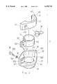
- FIG. 2 is an exploded perspective view showing an anchoring fixture of this invention
- FIG. 3 is a perspective showing a movable semilunar clamping piece of this invention.
- FIG. 4 is a perspective view showing an assembled anchoring fixture of this invention.
- FIG. 5 is a top view of an anchoring fixture of this invention.
- FIG. 6 is a perspective view showing the assembling of an anchoring fixture to a musical instrument holder of this invention.
- FIG. 7 is a cutaway sectional view of an assembled anchoring fixture and a musical instrument holder of this invention.
- this invention relating to an improved structure of an anchoring fixture for holding a musical instrument, wherein the anchoring fixture 3 contains a clamp socket 30 usually made of a metallic material.
- An oval platform 31 is provided to the clamp socket 30; and a hollow circular piece 32 is disposed underneath the platform 31 at the center position of its bottom face.
- a through hole 33 in a diameter corresponding to inner diameter of the circular piece 32 is formed at the center position of the platform 31 for communication with the circular piece 32.
- a semilunar clamping wall 34 is formed along a long lateral edge, and a semi-circular recess 35 is arranged at a position facing the through hole 33.
- a U-turn connecting end 36 of the clamping wall 34 locates at an end of the platform 31, and a vertical arc groove channel 361 is engraved at the central portion in the wall of the connecting end 36 facing straightly to the through hole 33, also, a positioning hole 362 is arranged on the platform 31 in front of the groove channel 361.
- a pinch-to-lock end 37 that is offered at another end of the clamping wall 34 locates at the other end of the platform 31.
- a recess 371 is prepared to a lateral plain face of the pinch-to-lock end 37, wherein an end of the recess 371 facing the through hole 33 is open, and a rectangular channel 372 is provided in a bottom wall of the recess 371 for a rectangular portion 380 of a bolt 38 with a washer 381 to pass through.
- a connecting end 41 is formed in a movable semilunar clamping piece 40 made of a metallic material, wherein the connecting end 41 is extended outwards to form a vertical connecting rod 411, which is further extended downwards from its bottom end to form a protruded portion.
- the connecting rod 411 is inserted in the groove channel 361 and the protruded portion enters the positioning hole 362 when the movable clamping piece 40 is positioned on the platform 31 along another long lateral edge.
- the movable clamping piece 40 can be opened or closed slightly.
- Another semi-circular recess 42 is formed in the central portion of the movable clamping piece 40 to combine with the circular recess 35 of the clamping wall 34 to form a circular space.
- Another pinch-to-lock end 43 is provided at the other end of the movable clamping piece 40, wherein a plain face, a recess 431, and a channel 432 are offered as same as that in the clamping wall 34; the channel 432 is formed in a bottom wall of recess 431 and; accommodates the bolt 38 to pass through; and the bolt 38 is equipped with a butterfly-nut 39.
- An open ring piece 50 made of plastic material is disposed in the circular space enclosed by the semi-circular recess 35, 42, wherein an outer rim portion of the ring piece 50 locates on the platform 31, its inner rim portion is slightly protruded over the through hole 33.
- Two side walls of a gap opening 51 in the ring piece 50 are extended outwards in parallel to form two insertion plates 52, 52' that will locate at the recess 371 and 431 respectively when the clamping wall 34 and the movable clamping piece 40 are joined to close. And moreover, each of those two insertion plate 52, 52' is provided with a circular hole 521 for the bolt 38 to penetrate.
- the anchoring fixture 3 is assembled onto a conventional holder for a musical instrument, wherein the holder comprises a tripod 10, a stationary upright central tube 11, and a movable adjusting tube 12 as described above.
- the circular piece 32 of the clamp socket 30 is applied to collar and cling onto the upright central tube 11 at its top end, and an adjustable tube 12 is guided through the enhancing ring piece 50 between the clamping wall 34 and the slightly opened movable clamping piece 40 and is telescopically received in the upright central tube 11.
- the butterfly-nut 39 is screwed to lock the movable clamping piece 40 to compress on the adjustable tube 12 via the enhancing ring piece 50.
- the anchoring fixture 3 As the circular piece 32 of the anchoring fixture 3 is used to collar tightly onto the top end of the upright central tube 11, unless a considerable external force is exerted, the anchoring fixture 3 can barely be turned, and when the anchoring fixture 3 is locked, the compressed adjustable tube 12 cannot be turned to move even a slight offset, and thereby, a musical instrument set on top of the adjustable tube 12 can be kept at a preset orientation. Further, after the anchoring fixture 3 is set clamping onto the adjustable tube 12, owing to compression of the movable clamping piece 40 and the ring piece 50, the adjustable tube 12 cannot be moved up or down in order to keep it at a constant height.
- the clamping portion of the anchoring fixture 3 is constructed by two independent portions--the fixed clamping wall 34 and the movable clamping piece 40, the elastic rebound force in a conventional U-type anchoring fixture 3 is eliminated thoroughly, therefore, it requires only a relatively smaller force to screw the butterfly-nut 39 tightly.
- the enhancing ring piece 50 is helpful to the anchoring fixture 3 for pressing hard to the adjustable tube 12 to obtain a positioning efficacy.
- all a user has to do is to release slightly the butterfly-nut 39, the adjustable tube 12 can be regulated again.
Abstract
An anchoring fixture for a musical instrument comprising a clamp socket with a platform, the platform having a hollow circular piece arranged on its bottom face, a through hole in its center position for communication with the hollow circular piece. A fixed clamping wall and a movable clamping piece are provided on a top face of the platform at its lateral edge. One end of the movable clamping piece is extended to form a protruded connecting rod, which is inserted in an arc groove channel in the fixed clamping wall. In the central portion of the fixed clamping wall and the movable clamping piece, a semi-circular recess is formed respectively, and an enhancing ring piece locates at an enclosed space formed by the semi-circular recesses. The circular piece of the clamp socket collars onto a top end of a central tube in a musical instrument holder, and an adjustable tube of the musical instrument holder penetrates the enhancing ring piece as well as the through hole in the platform to enter the central tube for completing assembly of the fixture.
Description
This invention relates to a fixture for holding a musical instrument, more particularly to an improved structure of an anchoring fixture for holding a musical instrument.
A general holder for a musical instrument (As shown in FIG. 1) contains a tripod, wherein a metallic upright central tube is erected, an adjustable tube is sleeve-jointed thereto, and an anchoring fixture is disposed on top of the adjustable tube for anchoring a musical instrument. A protruded strip formed on the surface of the upright central tube is extended along the longitudinal direction to coincide with a groove formed on an inner wall of the adjustable tube for height regulation, and a musical instrument can be kept on top of an adjustable tube in a preset orientation without turning about.
When the adjustable tube is regulated to a desired height, it will be locked by an anchoring fixture, which is an approximate U-shape clamp including two opposite semi-circular grooves combined to form a circle with an opening for collaring onto the adjustable tube. A bolt is used to screw together a pair of tapped holes at opposite ends of a clamp for locking the clamp on the adjustable tube, wherein a bottom rim of the anchoring clamp clings onto the central tube. A U-shape conventional anchoring clamp usually made of a metallic material will resist against an external force, therefore it requires a rather large force to pinch those two ends of the clamp together and screw a bolt into two tapped holes of the clamp. It may not be an easy job for a weak person to complete, and meanwhile, in the case of a loose fixing, the hung musical instrument may descend owing to gravity. In addition, the structure of a conventional anchoring clamp requires a protruded strip and a cooperative groove to avoid turning of the adjusting tube that can not be constrained by a mere anchoring clamp.
This invention is proposed to mainly provide an improved structure of an anchoring fixture for holding a musical instrument. The improved anchoring fixture is used to collar through an upright central tube of a musical instrument holder or tripod to clench onto an adjustable tube and keep it at a desired height without turning about. As to attain more convenient operation and better fixing efficacy than a conventional anchoring fixture for holding a musical instrument, the embodied skill of this invention is summarized as the following:
An improved structure of an anchoring fixture for holding a musical instrument contains a clamp socket with a platform, wherein a hollow circular piece is disposed at bottom of the platform; a through hole is formed in central portion of the platform to communicate with the circular piece; on top face of the platform, a fixed semilunar clamping wall and a movable semilunar clamping piece are provided; a protruded connecting portion at one end of the movable semilunar clamping piece is inserted in an arc groove channel of the fixed semilunar clamping wall; at center position of the fixed semilunar clamping wall and the movable clamping piece, a semi-circular groove is formed respectively, and a circular space enclosed by those two circular grooves is supplied with an enhancing ring piece, while the other end of the fixed semilunar clamping wall and the movable semilunar clamping piece are locked by a bolt; the assembled circular piece of the clamp socket collars onto the upright central tube at its top end of a musical instrument holder, the adjusting tube passes through the enhancing ring piece and the through hole in the platform to enter the upright central tube, and after the bolt is locked, the adjusting tube will be kept at a desired height without turning about.
For a better understanding to the present invention, together with further advantages or features thereof, at least one preferred embodiment will be elucidated below with reference to the annexed drawings in which:
FIG. 1 is a perspective view of a musical instrument holder and its anchoring fixture according to the prior art.
FIG. 2 is an exploded perspective view showing an anchoring fixture of this invention;
FIG. 3 is a perspective showing a movable semilunar clamping piece of this invention;
FIG. 4 is a perspective view showing an assembled anchoring fixture of this invention;
FIG. 5 is a top view of an anchoring fixture of this invention;
FIG. 6 is a perspective view showing the assembling of an anchoring fixture to a musical instrument holder of this invention;
FIG. 7 is a cutaway sectional view of an assembled anchoring fixture and a musical instrument holder of this invention.
As shown in FIG. 2 through FIG. 4, this invention relating to an improved structure of an anchoring fixture for holding a musical instrument, wherein the anchoring fixture 3 contains a clamp socket 30 usually made of a metallic material. An oval platform 31 is provided to the clamp socket 30; and a hollow circular piece 32 is disposed underneath the platform 31 at the center position of its bottom face. A through hole 33 in a diameter corresponding to inner diameter of the circular piece 32 is formed at the center position of the platform 31 for communication with the circular piece 32. On the top face of the platform 31, a semilunar clamping wall 34 is formed along a long lateral edge, and a semi-circular recess 35 is arranged at a position facing the through hole 33. A U-turn connecting end 36 of the clamping wall 34 locates at an end of the platform 31, and a vertical arc groove channel 361 is engraved at the central portion in the wall of the connecting end 36 facing straightly to the through hole 33, also, a positioning hole 362 is arranged on the platform 31 in front of the groove channel 361. A pinch-to-lock end 37 that is offered at another end of the clamping wall 34 locates at the other end of the platform 31. A recess 371 is prepared to a lateral plain face of the pinch-to-lock end 37, wherein an end of the recess 371 facing the through hole 33 is open, and a rectangular channel 372 is provided in a bottom wall of the recess 371 for a rectangular portion 380 of a bolt 38 with a washer 381 to pass through. A connecting end 41 is formed in a movable semilunar clamping piece 40 made of a metallic material, wherein the connecting end 41 is extended outwards to form a vertical connecting rod 411, which is further extended downwards from its bottom end to form a protruded portion. The connecting rod 411 is inserted in the groove channel 361 and the protruded portion enters the positioning hole 362 when the movable clamping piece 40 is positioned on the platform 31 along another long lateral edge. By virtue of cooperation between the connecting rod 411 and the groove channel 361 as well as the positioning hole 362, the movable clamping piece 40 can be opened or closed slightly. Another semi-circular recess 42 is formed in the central portion of the movable clamping piece 40 to combine with the circular recess 35 of the clamping wall 34 to form a circular space. Another pinch-to-lock end 43 is provided at the other end of the movable clamping piece 40, wherein a plain face, a recess 431, and a channel 432 are offered as same as that in the clamping wall 34; the channel 432 is formed in a bottom wall of recess 431 and; accommodates the bolt 38 to pass through; and the bolt 38 is equipped with a butterfly-nut 39. An open ring piece 50 made of plastic material is disposed in the circular space enclosed by the semi-circular recess 35, 42, wherein an outer rim portion of the ring piece 50 locates on the platform 31, its inner rim portion is slightly protruded over the through hole 33. Two side walls of a gap opening 51 in the ring piece 50 are extended outwards in parallel to form two insertion plates 52, 52' that will locate at the recess 371 and 431 respectively when the clamping wall 34 and the movable clamping piece 40 are joined to close. And moreover, each of those two insertion plate 52, 52' is provided with a circular hole 521 for the bolt 38 to penetrate.
As shown in FIG. 5 and 6, according to the above-described structure of this invention, the anchoring fixture 3 is assembled onto a conventional holder for a musical instrument, wherein the holder comprises a tripod 10, a stationary upright central tube 11, and a movable adjusting tube 12 as described above. The circular piece 32 of the clamp socket 30 is applied to collar and cling onto the upright central tube 11 at its top end, and an adjustable tube 12 is guided through the enhancing ring piece 50 between the clamping wall 34 and the slightly opened movable clamping piece 40 and is telescopically received in the upright central tube 11. When a desired height of the adjustable tube 12 is reached, the butterfly-nut 39 is screwed to lock the movable clamping piece 40 to compress on the adjustable tube 12 via the enhancing ring piece 50.
As the circular piece 32 of the anchoring fixture 3 is used to collar tightly onto the top end of the upright central tube 11, unless a considerable external force is exerted, the anchoring fixture 3 can barely be turned, and when the anchoring fixture 3 is locked, the compressed adjustable tube 12 cannot be turned to move even a slight offset, and thereby, a musical instrument set on top of the adjustable tube 12 can be kept at a preset orientation. Further, after the anchoring fixture 3 is set clamping onto the adjustable tube 12, owing to compression of the movable clamping piece 40 and the ring piece 50, the adjustable tube 12 cannot be moved up or down in order to keep it at a constant height. As the clamping portion of the anchoring fixture 3 is constructed by two independent portions--the fixed clamping wall 34 and the movable clamping piece 40, the elastic rebound force in a conventional U-type anchoring fixture 3 is eliminated thoroughly, therefore, it requires only a relatively smaller force to screw the butterfly-nut 39 tightly. Besides, the enhancing ring piece 50 is helpful to the anchoring fixture 3 for pressing hard to the adjustable tube 12 to obtain a positioning efficacy. On the contrary, when releasing the anchoring fixture 3 is desired, all a user has to do is to release slightly the butterfly-nut 39, the adjustable tube 12 can be regulated again.
Claims (1)
1. An anchoring fixture for maintaining an adjustable tube in a desired position relative to a central tube wherein the adjustable tube is telescopically received within the central tube, the anchoring fixture comprising:
a) a clamp socket including an oval platform having a top face and a bottom face, a hollow circular piece extending from the bottom face, a through hole formed in the platform and communicating with the interior of the circular piece, the interior of the circular piece and the through hole having a common diameter, and a positioning hole formed in the top face;
b) a semilunar fixed clamping wall on the top face, the fixed clamping wall including a first semicircular recess extending around the through hole, a first end having a vertical groove channel facing the through hole and adjacent the positioning hole, and a second end including a first locking recess formed therein and a first bolt hole extending through a bottom wall of the first locking recess;
c) a movable clamping wall including a second semicircular recess, a first end having a vertical rod terminating in a protruded portion, the vertical rod being engagable within the groove channel and the protruded portion being engagable within the positioning hole for permitting pivotal movement of the movable clamping wall relative to the fixed clamping wall, and a second end including a second locking recess and a second bolt hole extending through a bottom wall of the second locking recess;
d) an open ring disposable within an enclosed space defined by the first and second semicircular recesses, the ring including a gap formed by a pair of spaced wall ends, a plate extending outwardly from each wall end and disposed in parallel with each other, each plate having a hole formed therethrough, one plate being receivable within the first locking recess and the other plate being receivable within the second locking recess to dispose the bolt holes of the locking recesses and the holes of the plates in alignment; and
e) a bolt extendable through the bolt holes of the locking recesses and holes of the plates for securing the movable clamping member to the fixed clamping member, the ring around the adjustable tube and enclosing the plates of the ring within the first and the second locking recesses.
Priority Applications (1)
| Application Number | Priority Date | Filing Date | Title |
|---|---|---|---|
| US09/208,016 US6155743A (en) | 1998-12-09 | 1998-12-09 | Anchoring fixture for holding a musical instrument |
Applications Claiming Priority (1)
| Application Number | Priority Date | Filing Date | Title |
|---|---|---|---|
| US09/208,016 US6155743A (en) | 1998-12-09 | 1998-12-09 | Anchoring fixture for holding a musical instrument |
Publications (1)
| Publication Number | Publication Date |
|---|---|
| US6155743A true US6155743A (en) | 2000-12-05 |
Family
ID=22772879
Family Applications (1)
| Application Number | Title | Priority Date | Filing Date |
|---|---|---|---|
| US09/208,016 Expired - Lifetime US6155743A (en) | 1998-12-09 | 1998-12-09 | Anchoring fixture for holding a musical instrument |
Country Status (1)
| Country | Link |
|---|---|
| US (1) | US6155743A (en) |
Cited By (47)
| Publication number | Priority date | Publication date | Assignee | Title |
|---|---|---|---|---|
| US6343992B2 (en) * | 1998-08-31 | 2002-02-05 | Lindsay Manufacturing Co. | Driver coupler |
| US6345794B1 (en) * | 1999-07-07 | 2002-02-12 | Fusion Specialties, Inc. | Adjustable pole holder adapted for form support |
| EP1180607A1 (en) * | 2000-08-12 | 2002-02-20 | RK Rose + Krieger GmbH & Co. KG Verbindungs- und Positioniersysteme | Clamping element |
| US6364372B1 (en) * | 1999-11-19 | 2002-04-02 | Ali Marandi | Fitting with integral half clamp |
| US6520710B2 (en) * | 2001-02-14 | 2003-02-18 | Delphi Technologies, Inc. | Powdered metal assemblies with fastener inserts |
| US6578804B2 (en) * | 2001-06-08 | 2003-06-17 | Ming Chuan Lin | Securing device for positioning a seat post of office chairs |
| US20040056527A1 (en) * | 2000-05-15 | 2004-03-25 | Lance Mark Andrew | Clamp for a lumbar support |
| US20040136775A1 (en) * | 2003-01-15 | 2004-07-15 | Jung-Pin Chang | Tripod joint |
| WO2004082554A2 (en) * | 2003-03-18 | 2004-09-30 | Hill-Rom Services, Inc. | Patient care equipment management system |
| US20040199996A1 (en) * | 2003-03-18 | 2004-10-14 | Newkirk David C. | Radial arm system for patient care equipment |
| US20040232286A1 (en) * | 2003-03-18 | 2004-11-25 | Newkirk David C. | Patient line management system |
| US20040258875A1 (en) * | 2003-06-20 | 2004-12-23 | Nell Richard T. | Hinged annular shaft flange |
| US6908249B2 (en) * | 2000-12-27 | 2005-06-21 | Erwin Tomm | Lever-activated lock for telescoping pole |
| US6935267B1 (en) * | 2004-10-27 | 2005-08-30 | Oren Cotton | Vented fuel filler and method of installation |
| US20060179571A1 (en) * | 2005-02-11 | 2006-08-17 | Hill-Rom Services, Inc. | Transferable patient care equipment support |
| US20070012848A1 (en) * | 2005-07-18 | 2007-01-18 | Tsun-Chi Liao | Anchoring fixture for stools capable of adjusting elevation |
| US20070252053A1 (en) * | 2003-10-10 | 2007-11-01 | Rory Brooke | Self-Stabilizing Support Assembly for an Item Furniture |
| US20090178987A1 (en) * | 2008-01-12 | 2009-07-16 | Vale Mill (Rochdale) Limited | Clothes airer |
| US7676865B2 (en) | 2003-10-13 | 2010-03-16 | Hill-Rom Services, Inc. | Transferable patient care equipment support |
| US7735266B2 (en) | 2001-05-25 | 2010-06-15 | Hill-Rom Services, Inc. | Architectural system having transferrable life support cart |
| US7748672B2 (en) | 2007-09-07 | 2010-07-06 | Hill-Rom Services, Inc. | Transferable patient care equipment support |
| US7798456B2 (en) | 2007-08-21 | 2010-09-21 | Hill-Rom Services, Inc. | Transferable patient care equipment support |
| US20100254756A1 (en) * | 2009-04-02 | 2010-10-07 | Douglas Chiang | Bicycle Seat Post Protecting Member |
| US20100295350A1 (en) * | 2008-12-18 | 2010-11-25 | Daniel Seth Barman | Ergonomic musician's stool |
| US7865983B2 (en) | 2007-04-26 | 2011-01-11 | Hill-Rom Services, Inc. | Patient care equipment support transfer system |
| CN102005203A (en) * | 2009-08-31 | 2011-04-06 | 罗兰株式会社 | Clamps for musical instrument stand |
| US20110103885A1 (en) * | 2009-11-05 | 2011-05-05 | Jin-Cang Li | Retaining Device for Tube Member |
| US20110168219A1 (en) * | 2010-01-13 | 2011-07-14 | Edward Griffith | Vehicle anchored accessary holder and associated methods |
| US8051610B2 (en) | 2004-09-22 | 2011-11-08 | Hill-Rom Services, Inc. | Patient flatwall system |
| US8104729B2 (en) | 2007-03-09 | 2012-01-31 | Hill-Rom Services, Inc. | Transferable patient care equipment support |
| US20120034023A1 (en) * | 2010-08-09 | 2012-02-09 | Wang Kun-Jie | Telescopic Apparatus |
| US20130111712A1 (en) * | 2011-11-03 | 2013-05-09 | Hsin-Yuan Lai | Clamping device for a telescopic rod |
| DE102009017310B4 (en) * | 2009-04-11 | 2014-01-23 | MPM Micro Präzision Marx GmbH | Profile construction with compact connecting elements and connecting element for such a profile construction |
| US20150027268A1 (en) * | 2009-11-05 | 2015-01-29 | Jin-Cang Li | Bicycle Handle Assembly For Handlebar |
| US20150240850A1 (en) * | 2014-02-27 | 2015-08-27 | Hoshino Gakki Co., Ltd. | Pipe holding device |
| US20160215803A1 (en) * | 2015-01-27 | 2016-07-28 | Chien-Ting Lin | Fastening device having a tubular sleeve member for mounting on a tube or immobilizing two telescopically connected tubes |
| US9472936B2 (en) * | 2014-09-28 | 2016-10-18 | Joe Sousa | Nonmetallic sheathed electrical cable mounting |
| CN106678520A (en) * | 2016-09-30 | 2017-05-17 | 中光华研电子科技有限公司 | Stable supporting device for portable precise instrument |
| USD802406S1 (en) * | 2015-06-05 | 2017-11-14 | Phillips Ormonde & Fitzpatrick | Connection fixture |
| US10051930B2 (en) * | 2013-09-27 | 2018-08-21 | Lekisport Ag | Length-adjustable pole and clamping apparatus therefor |
| CN108993158A (en) * | 2018-07-20 | 2018-12-14 | 芜湖新瑟安智能科技有限公司 | A kind of box membrane separation device |
| USD856125S1 (en) * | 2017-05-18 | 2019-08-13 | Wayne Milner | Connection fixture |
| US10465402B2 (en) * | 2015-02-23 | 2019-11-05 | Spanset Inter Ag | Assembly of a platform assembly and support structure and method of assembly |
| US11035558B2 (en) * | 2019-06-26 | 2021-06-15 | Hme, Incorporated | Pole assembly and method of use |
| US20220154916A1 (en) * | 2020-11-16 | 2022-05-19 | Mitutoyo Corporation | Fixing device |
| US11459785B2 (en) * | 2018-12-17 | 2022-10-04 | Martin Simmons | Post socket |
| US11862360B2 (en) * | 2017-03-21 | 2024-01-02 | Hubbell Incorporated | Non-conductive support stands |
Citations (12)
| Publication number | Priority date | Publication date | Assignee | Title |
|---|---|---|---|---|
| US2991495A (en) * | 1958-10-13 | 1961-07-11 | Orville A Blalack | Shoe shine stand |
| US3606409A (en) * | 1969-09-30 | 1971-09-20 | Hawkins Hawkins Co Inc | Clamping device |
| US4111575A (en) * | 1976-06-11 | 1978-09-05 | Masao Hoshino | Tube coupling |
| US4185808A (en) * | 1975-02-10 | 1980-01-29 | Cbs Inc. | Connector hardware for percussive instruments |
| US4373235A (en) * | 1982-01-18 | 1983-02-15 | Jaising Korgaonkar | Pipe clamp |
| US4497092A (en) * | 1982-07-12 | 1985-02-05 | Hoshino Gakki Company, Ltd. | Device for fixing rods in selected relative position |
| US4744690A (en) * | 1987-09-18 | 1988-05-17 | Hsieh Wu H | Stabilizer for telescopic stands |
| US5139358A (en) * | 1990-05-09 | 1992-08-18 | Kioritz Corporation | Part mount device |
| US5722627A (en) * | 1996-05-28 | 1998-03-03 | Hoshino Gakki Kabushiki Kaisha | Mechanism for adjusting the height of a drum chair or the like chair |
| US5738326A (en) * | 1996-10-16 | 1998-04-14 | Hwa Shin Musical Instrument Co. Ltd. | Seat stem positioning structure of a chair for drummer |
| US5927810A (en) * | 1998-07-23 | 1999-07-27 | Hwa Hsin Musical Instrument Co., Ltd. | Adjustable musician's chair |
| US5941653A (en) * | 1996-05-30 | 1999-08-24 | Alstom Transport Electrification S.P.A. | Composite structure and method for its assembly |
-
1998
- 1998-12-09 US US09/208,016 patent/US6155743A/en not_active Expired - Lifetime
Patent Citations (12)
| Publication number | Priority date | Publication date | Assignee | Title |
|---|---|---|---|---|
| US2991495A (en) * | 1958-10-13 | 1961-07-11 | Orville A Blalack | Shoe shine stand |
| US3606409A (en) * | 1969-09-30 | 1971-09-20 | Hawkins Hawkins Co Inc | Clamping device |
| US4185808A (en) * | 1975-02-10 | 1980-01-29 | Cbs Inc. | Connector hardware for percussive instruments |
| US4111575A (en) * | 1976-06-11 | 1978-09-05 | Masao Hoshino | Tube coupling |
| US4373235A (en) * | 1982-01-18 | 1983-02-15 | Jaising Korgaonkar | Pipe clamp |
| US4497092A (en) * | 1982-07-12 | 1985-02-05 | Hoshino Gakki Company, Ltd. | Device for fixing rods in selected relative position |
| US4744690A (en) * | 1987-09-18 | 1988-05-17 | Hsieh Wu H | Stabilizer for telescopic stands |
| US5139358A (en) * | 1990-05-09 | 1992-08-18 | Kioritz Corporation | Part mount device |
| US5722627A (en) * | 1996-05-28 | 1998-03-03 | Hoshino Gakki Kabushiki Kaisha | Mechanism for adjusting the height of a drum chair or the like chair |
| US5941653A (en) * | 1996-05-30 | 1999-08-24 | Alstom Transport Electrification S.P.A. | Composite structure and method for its assembly |
| US5738326A (en) * | 1996-10-16 | 1998-04-14 | Hwa Shin Musical Instrument Co. Ltd. | Seat stem positioning structure of a chair for drummer |
| US5927810A (en) * | 1998-07-23 | 1999-07-27 | Hwa Hsin Musical Instrument Co., Ltd. | Adjustable musician's chair |
Cited By (71)
| Publication number | Priority date | Publication date | Assignee | Title |
|---|---|---|---|---|
| US6343992B2 (en) * | 1998-08-31 | 2002-02-05 | Lindsay Manufacturing Co. | Driver coupler |
| US6345794B1 (en) * | 1999-07-07 | 2002-02-12 | Fusion Specialties, Inc. | Adjustable pole holder adapted for form support |
| US6364372B1 (en) * | 1999-11-19 | 2002-04-02 | Ali Marandi | Fitting with integral half clamp |
| US20040056527A1 (en) * | 2000-05-15 | 2004-03-25 | Lance Mark Andrew | Clamp for a lumbar support |
| EP1180607A1 (en) * | 2000-08-12 | 2002-02-20 | RK Rose + Krieger GmbH & Co. KG Verbindungs- und Positioniersysteme | Clamping element |
| US6908249B2 (en) * | 2000-12-27 | 2005-06-21 | Erwin Tomm | Lever-activated lock for telescoping pole |
| US6520710B2 (en) * | 2001-02-14 | 2003-02-18 | Delphi Technologies, Inc. | Powdered metal assemblies with fastener inserts |
| US7735266B2 (en) | 2001-05-25 | 2010-06-15 | Hill-Rom Services, Inc. | Architectural system having transferrable life support cart |
| US6578804B2 (en) * | 2001-06-08 | 2003-06-17 | Ming Chuan Lin | Securing device for positioning a seat post of office chairs |
| US20040136775A1 (en) * | 2003-01-15 | 2004-07-15 | Jung-Pin Chang | Tripod joint |
| US7065812B2 (en) | 2003-03-18 | 2006-06-27 | Hill-Rom Services, Inc. | Patient care equipment management system |
| US7083150B2 (en) | 2003-03-18 | 2006-08-01 | Hill-Rom Services, Inc. | Patient line management system |
| WO2004082554A3 (en) * | 2003-03-18 | 2005-03-24 | Hill Rom Services Inc | Patient care equipment management system |
| US20040232286A1 (en) * | 2003-03-18 | 2004-11-25 | Newkirk David C. | Patient line management system |
| US20040199996A1 (en) * | 2003-03-18 | 2004-10-14 | Newkirk David C. | Radial arm system for patient care equipment |
| US7921489B2 (en) | 2003-03-18 | 2011-04-12 | Hill-Rom Services, Inc. | Radial arm system for patient care equipment |
| WO2004082554A2 (en) * | 2003-03-18 | 2004-09-30 | Hill-Rom Services, Inc. | Patient care equipment management system |
| US7216382B2 (en) | 2003-03-18 | 2007-05-15 | Hill-Rom Services, Inc. | Patient care equipment management system |
| US7735788B2 (en) | 2003-03-18 | 2010-06-15 | Hill-Rom Services, Inc. | Patient care equipment management system |
| US8336138B2 (en) | 2003-03-18 | 2012-12-25 | Hill-Rom Services, Inc. | Radial arm system for patient care equipment |
| US20040258875A1 (en) * | 2003-06-20 | 2004-12-23 | Nell Richard T. | Hinged annular shaft flange |
| US6935806B2 (en) * | 2003-06-20 | 2005-08-30 | Waukesha Tool & Stamping, Inc. | Hinged annular shaft flange |
| AU2004281063B2 (en) * | 2003-10-10 | 2011-01-20 | Hedera Ab | A self-stabilizing support assembly for an item furniture |
| US20070252053A1 (en) * | 2003-10-10 | 2007-11-01 | Rory Brooke | Self-Stabilizing Support Assembly for an Item Furniture |
| US7677524B2 (en) * | 2003-10-10 | 2010-03-16 | Hedera Ab | Self-stabilizing support assembly for an item furniture |
| US7676865B2 (en) | 2003-10-13 | 2010-03-16 | Hill-Rom Services, Inc. | Transferable patient care equipment support |
| US8051610B2 (en) | 2004-09-22 | 2011-11-08 | Hill-Rom Services, Inc. | Patient flatwall system |
| US8678334B2 (en) | 2004-09-22 | 2014-03-25 | Hill-Rom Services, Inc. | Patient flatwall system |
| US6935267B1 (en) * | 2004-10-27 | 2005-08-30 | Oren Cotton | Vented fuel filler and method of installation |
| US7884735B2 (en) | 2005-02-11 | 2011-02-08 | Hill-Rom Services, Inc. | Transferable patient care equipment support |
| US8258973B2 (en) | 2005-02-11 | 2012-09-04 | Hill-Rom Services, Inc. | Transferable patient care equipment support |
| US20060179571A1 (en) * | 2005-02-11 | 2006-08-17 | Hill-Rom Services, Inc. | Transferable patient care equipment support |
| US7234781B2 (en) * | 2005-07-18 | 2007-06-26 | Tsun-Chi Liao | Anchoring fixture for stools capable of adjusting elevation |
| US20070012848A1 (en) * | 2005-07-18 | 2007-01-18 | Tsun-Chi Liao | Anchoring fixture for stools capable of adjusting elevation |
| US8104729B2 (en) | 2007-03-09 | 2012-01-31 | Hill-Rom Services, Inc. | Transferable patient care equipment support |
| US8056162B2 (en) | 2007-04-26 | 2011-11-15 | Hill-Rom Services, Inc. | Patient support apparatus with motorized traction control |
| US7865983B2 (en) | 2007-04-26 | 2011-01-11 | Hill-Rom Services, Inc. | Patient care equipment support transfer system |
| US7798456B2 (en) | 2007-08-21 | 2010-09-21 | Hill-Rom Services, Inc. | Transferable patient care equipment support |
| US8047484B2 (en) | 2007-08-21 | 2011-11-01 | Hill-Rom Services, Inc. | Transferable patient care equipment support |
| US7748672B2 (en) | 2007-09-07 | 2010-07-06 | Hill-Rom Services, Inc. | Transferable patient care equipment support |
| US20090178987A1 (en) * | 2008-01-12 | 2009-07-16 | Vale Mill (Rochdale) Limited | Clothes airer |
| US8100274B2 (en) * | 2008-01-12 | 2012-01-24 | Vale Mill (Rochdale) Limited | Clothes airer |
| US20100295350A1 (en) * | 2008-12-18 | 2010-11-25 | Daniel Seth Barman | Ergonomic musician's stool |
| US20100254756A1 (en) * | 2009-04-02 | 2010-10-07 | Douglas Chiang | Bicycle Seat Post Protecting Member |
| DE102009017310B4 (en) * | 2009-04-11 | 2014-01-23 | MPM Micro Präzision Marx GmbH | Profile construction with compact connecting elements and connecting element for such a profile construction |
| CN102005203A (en) * | 2009-08-31 | 2011-04-06 | 罗兰株式会社 | Clamps for musical instrument stand |
| US9038501B2 (en) * | 2009-11-05 | 2015-05-26 | Hung Chung Tien International Co., Ltd. | Bicycle handle assembly for handlebar |
| US20150027268A1 (en) * | 2009-11-05 | 2015-01-29 | Jin-Cang Li | Bicycle Handle Assembly For Handlebar |
| DE102010017732B4 (en) * | 2009-11-05 | 2015-02-19 | Hung Chung Tien International Co., Ltd. | Pipe clamp connector and assembly with a pipe, a handle and a pipe clamp connector |
| US20110103885A1 (en) * | 2009-11-05 | 2011-05-05 | Jin-Cang Li | Retaining Device for Tube Member |
| US8776811B2 (en) * | 2010-01-13 | 2014-07-15 | Edward Griffith | Vehicle anchored accessory holder and associated methods |
| US20110168219A1 (en) * | 2010-01-13 | 2011-07-14 | Edward Griffith | Vehicle anchored accessary holder and associated methods |
| US20120034023A1 (en) * | 2010-08-09 | 2012-02-09 | Wang Kun-Jie | Telescopic Apparatus |
| US20130111712A1 (en) * | 2011-11-03 | 2013-05-09 | Hsin-Yuan Lai | Clamping device for a telescopic rod |
| US8608118B2 (en) * | 2011-11-03 | 2013-12-17 | Hsin-Yuan Lai | Clamping device for a telescopic rod |
| US10051930B2 (en) * | 2013-09-27 | 2018-08-21 | Lekisport Ag | Length-adjustable pole and clamping apparatus therefor |
| US9631656B2 (en) * | 2014-02-27 | 2017-04-25 | Hoshino Gakki Co., Ltd. | Pipe holding device |
| JP2015161368A (en) * | 2014-02-27 | 2015-09-07 | 星野楽器株式会社 | pipe holding device |
| US20150240850A1 (en) * | 2014-02-27 | 2015-08-27 | Hoshino Gakki Co., Ltd. | Pipe holding device |
| US9472936B2 (en) * | 2014-09-28 | 2016-10-18 | Joe Sousa | Nonmetallic sheathed electrical cable mounting |
| US20160215803A1 (en) * | 2015-01-27 | 2016-07-28 | Chien-Ting Lin | Fastening device having a tubular sleeve member for mounting on a tube or immobilizing two telescopically connected tubes |
| US10288102B2 (en) * | 2015-01-27 | 2019-05-14 | Chien-Ting Lin | Fastening device having a tubular sleeve member for mounting on a tube or immobilizing two telescopically connected tubes |
| US10465402B2 (en) * | 2015-02-23 | 2019-11-05 | Spanset Inter Ag | Assembly of a platform assembly and support structure and method of assembly |
| USD802406S1 (en) * | 2015-06-05 | 2017-11-14 | Phillips Ormonde & Fitzpatrick | Connection fixture |
| CN106678520A (en) * | 2016-09-30 | 2017-05-17 | 中光华研电子科技有限公司 | Stable supporting device for portable precise instrument |
| US11862360B2 (en) * | 2017-03-21 | 2024-01-02 | Hubbell Incorporated | Non-conductive support stands |
| USD856125S1 (en) * | 2017-05-18 | 2019-08-13 | Wayne Milner | Connection fixture |
| CN108993158A (en) * | 2018-07-20 | 2018-12-14 | 芜湖新瑟安智能科技有限公司 | A kind of box membrane separation device |
| US11459785B2 (en) * | 2018-12-17 | 2022-10-04 | Martin Simmons | Post socket |
| US11035558B2 (en) * | 2019-06-26 | 2021-06-15 | Hme, Incorporated | Pole assembly and method of use |
| US20220154916A1 (en) * | 2020-11-16 | 2022-05-19 | Mitutoyo Corporation | Fixing device |
Similar Documents
| Publication | Publication Date | Title |
|---|---|---|
| US6155743A (en) | Anchoring fixture for holding a musical instrument | |
| US6209829B1 (en) | Guitar stand | |
| US6010121A (en) | Work piece clamping device of workbench | |
| US5632049A (en) | Holder assembly for a shower head | |
| US6240815B1 (en) | Workpiece clamping device | |
| US6761274B1 (en) | Locating structure of expandable units of a rack | |
| USD413429S (en) | Clamp for supporting umbrella | |
| US20060177260A1 (en) | Retractable raiser | |
| USD414273S (en) | Puck spring for a sample tube holder | |
| US7815155B2 (en) | Suction device and supporting device having the same | |
| US5816734A (en) | Connection device | |
| US5605170A (en) | Crutch | |
| JP3127080U (en) | Tool chuck device | |
| US6942190B1 (en) | Sucker assembly | |
| US6241201B1 (en) | Support frame of golf bag | |
| USD459975S1 (en) | Elongate channel member | |
| US6226834B1 (en) | Handle structure for a luggage | |
| US6223392B1 (en) | Retractable handle assembly | |
| US6581767B2 (en) | Golf bag base | |
| US7059420B1 (en) | Structure for fastening detachably blade with handle of gardening implements | |
| US5944178A (en) | Suit hanger support of luggage | |
| US6454066B1 (en) | Luggage | |
| USD506261S1 (en) | Chromatography column locking ring | |
| US5863015A (en) | Microphone stand elevating device | |
| USD470596S1 (en) | Test kit specimen-handling tool |
Legal Events
| Date | Code | Title | Description |
|---|---|---|---|
| AS | Assignment |
Owner name: TAY-E CO., LTD., TAIWAN Free format text: ASSIGNMENT OF ASSIGNORS INTEREST;ASSIGNOR:CHEN, ERH-CHIANG;REEL/FRAME:009658/0192 Effective date: 19981127 |
|
| STCF | Information on status: patent grant |
Free format text: PATENTED CASE |
|
| FPAY | Fee payment |
Year of fee payment: 4 |
|
| FPAY | Fee payment |
Year of fee payment: 8 |
|
| FPAY | Fee payment |
Year of fee payment: 12 |