US6155947A - Speed-sensitive differential - Google Patents
Speed-sensitive differential Download PDFInfo
- Publication number
- US6155947A US6155947A US09/320,632 US32063299A US6155947A US 6155947 A US6155947 A US 6155947A US 32063299 A US32063299 A US 32063299A US 6155947 A US6155947 A US 6155947A
- Authority
- US
- United States
- Prior art keywords
- fluid
- pump
- carrier housing
- drivably
- differential mechanism
- Prior art date
- Legal status (The legal status is an assumption and is not a legal conclusion. Google has not performed a legal analysis and makes no representation as to the accuracy of the status listed.)
- Expired - Lifetime
Links
Images


Classifications
-
- F—MECHANICAL ENGINEERING; LIGHTING; HEATING; WEAPONS; BLASTING
- F16—ENGINEERING ELEMENTS AND UNITS; GENERAL MEASURES FOR PRODUCING AND MAINTAINING EFFECTIVE FUNCTIONING OF MACHINES OR INSTALLATIONS; THERMAL INSULATION IN GENERAL
- F16H—GEARING
- F16H48/00—Differential gearings
- F16H48/20—Arrangements for suppressing or influencing the differential action, e.g. locking devices
- F16H48/22—Arrangements for suppressing or influencing the differential action, e.g. locking devices using friction clutches or brakes
-
- F—MECHANICAL ENGINEERING; LIGHTING; HEATING; WEAPONS; BLASTING
- F16—ENGINEERING ELEMENTS AND UNITS; GENERAL MEASURES FOR PRODUCING AND MAINTAINING EFFECTIVE FUNCTIONING OF MACHINES OR INSTALLATIONS; THERMAL INSULATION IN GENERAL
- F16H—GEARING
- F16H48/00—Differential gearings
- F16H48/06—Differential gearings with gears having orbital motion
- F16H48/08—Differential gearings with gears having orbital motion comprising bevel gears
-
- F—MECHANICAL ENGINEERING; LIGHTING; HEATING; WEAPONS; BLASTING
- F16—ENGINEERING ELEMENTS AND UNITS; GENERAL MEASURES FOR PRODUCING AND MAINTAINING EFFECTIVE FUNCTIONING OF MACHINES OR INSTALLATIONS; THERMAL INSULATION IN GENERAL
- F16H—GEARING
- F16H48/00—Differential gearings
- F16H48/20—Arrangements for suppressing or influencing the differential action, e.g. locking devices
- F16H48/27—Arrangements for suppressing or influencing the differential action, e.g. locking devices using internally-actuatable fluid pressure, e.g. internal pump types
-
- F—MECHANICAL ENGINEERING; LIGHTING; HEATING; WEAPONS; BLASTING
- F16—ENGINEERING ELEMENTS AND UNITS; GENERAL MEASURES FOR PRODUCING AND MAINTAINING EFFECTIVE FUNCTIONING OF MACHINES OR INSTALLATIONS; THERMAL INSULATION IN GENERAL
- F16H—GEARING
- F16H48/00—Differential gearings
- F16H48/06—Differential gearings with gears having orbital motion
- F16H48/08—Differential gearings with gears having orbital motion comprising bevel gears
- F16H2048/085—Differential gearings with gears having orbital motion comprising bevel gears characterised by shafts or gear carriers for orbital gears
-
- F—MECHANICAL ENGINEERING; LIGHTING; HEATING; WEAPONS; BLASTING
- F16—ENGINEERING ELEMENTS AND UNITS; GENERAL MEASURES FOR PRODUCING AND MAINTAINING EFFECTIVE FUNCTIONING OF MACHINES OR INSTALLATIONS; THERMAL INSULATION IN GENERAL
- F16H—GEARING
- F16H48/00—Differential gearings
- F16H48/20—Arrangements for suppressing or influencing the differential action, e.g. locking devices
- F16H2048/201—Arrangements for suppressing or influencing the differential action, e.g. locking devices with means directly braking the orbital gears
Definitions
- the invention relates to differential gear mechanisms for transferring torque from a driving shaft to each of two traction wheels for a vehicle.
- the Gerotor pump has one pump member connected drivably to the differential carrier.
- a companion pump member is connected drivably to one of the driven shafts.
- the hydrostatic resistance provided by the pump members establishes a speed-sensitive torque bias because the energy applied to the fluid in the closed pump circuit is determined by the relative speeds of the side gear and the differential carrier.
- the total torque bias for the gear differential mechanism is the sum of the mechanical torque bias and the speed-sensitive torque bias.
- the differential carrier is driven by a crown gear or a ring gear, which is drivably engaged with a drive pinion.
- the combined torque bias provided by the clutches and the Gerotor pump improves the drivability of the vehicle by improving the steering response to a steering effort applied by the vehicle operator and by reducing the possibility of understeering.
- the hydrostatic torque bias component of the total torque bias is proportional to the relative speeds of the pump members regardless of the magnitude of the torque being transmitted through the differential.
- the geared differential mechanism of the invention is capable of delivering torque from a driving member to each of two driven members. Side gears are connected to the driven members.
- a carrier housing encloses the side gears and planetary pinions that engage the side gears.
- a pair of friction disk clutch packs have friction disks connected to the side gears and the carrier housing.
- a pair of pressure rings in the carrier housing surrounds the side gears, each pressure ring having ramp surfaces for transferring axial thrust forces to the clutch packs to create a torque-sensitive bias.
- a positive displacement pump has one pump member connected to the carrier housing and a second pump member connected to a side gear. Silicone fluid in a fluid reservoir formed in the carrier housing is distributed from the fluid reservoir and a fluid inlet port for the pump as fluid circulates through the pump to create a speed-sensitive bias.
- the differential mechanism of the invention overcomes the disadvantages of using an external Gerotor fluid supply and a complex fluid supply circuit extending to the Gerotor pump inlet. It does this by providing a reservoir which is filled with silicone fluid, the reservoir being situated within an end cap on the differential carrier in close proximity to the inlet and outlet ports of the Gerotor pump.
- the fluid chamber that contains the silicone fluid is in the form of an annulus, which is completely filled with silicone fluid.
- the silicone fluid is pressurized with a continuous pressure developed by a movable piston that forms one wall of the annulus that contains the silicone fluid.
- the piston is spring-biased to effect a continuous pressure to avoid cavitation of the silicone fluid as it circulates through the Gerotor pump. This ensures that the inlet port of the Gerotor pump is continuously supplied with silicone fluid during operation of the pump, as the differential mechanism develops a speed-sensitive torque bias.
- the silicone fluid has a thermal stability that is higher than the thermal stability of the fluid in the axle housing. Continuous differential action, in a prolonged turning maneuver of the vehicle, will develop internal heat in the silicone fluid, but that does not adversely affect the performance of the fluid since the effective operating temperature range for the silicone fluid is substantially greater than the effective operating range that would exist for conventional rear axle fluids, as in the case of the differential mechanism shown in the previously described copending patent application.
- FIG. 1 is a cross-sectional assembly view of a differential mechanism having a speed-sensitive torque bias feature with an internal silicone fluid reservoir;
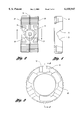
- FIG. 2 is a top view of a pair of pressure rings that are assembled in the carrier housing of the differential mechanism of FIG. 1;
- FIG. 3 is an end view of one of the pressure rings shown in FIG. 2;
- FIG. 4 is a cross-sectional view of the pressure ring of FIG. 3 as seen from the plane of section line 4--4 of FIG. 3;
- FIG. 5 is a cross-sectional view of the Gerotor pump as seen from the plane of section line 5--5 of FIG. 1;
- FIG. 6 is a perspective view of the flow control valve for the flow inlet and flow outlet ports of the pump of FIG. 5;
- FIG. 7 is a cross-sectional view of a valve port and flow control valve as seen from the plane of section line 7--7 of FIG. 6;
- FIG. 8 is a cross-sectional view taken along the plane of section line 8--8 of FIG. 1;
- FIG. 9 is a cross-sectional view taken along the plane of section line 9--9 of FIG. 8.
- FIG. 1 shows a differential housing 10 having an end bearing plate 12 secured to the right end to cover the opening at the right end.
- Plate 12 is secured to the housing 10 by threaded fasteners 14.
- the housing 10 has a first bearing opening that receives bearing 16, which rotatably supports differential carrier housing 18.
- End bearing plate 12 has a bearing opening for bearing 20, which rotatably supports a carrier housing end plate 22.
- Plate 22 is secured to the opening at the right end end of the carrier housing 18, threaded fasteners 24 being provided for this purpose.
- End member 26 is secured to the closure plate 22 by the threaded fasteners 24.
- Member 26 defines a sleeve shaft 28, which is journaled by bearing 20 in the bearing opening in end plate 12 for the differential housing.
- Torque output member 30 is journaled in the sleeve shaft 28 by bearing 32.
- Output member 30 is splined at 34 to a first side gear 36.
- Differential pinions 38 engage side gear 36 as well as a companion side gear 40.
- Pinions 38 are journaled on a spider member or pinion shaft member 42.
- Side gear 40 is splined at 46 to a second torque output member 48, the latter being journaled by bearing 50 in sleeve shaft 52, which forms a part of the carrier housing 18.
- Torque output members 30 and 48 are connected respectively to universal joints, which include a universal joint member 54 and 56, respectively.
- Member 54 is journaled by bearing 58 in the end wall 12.
- a first friction disk pack 60 includes clutch separator plates splined to internal spline teeth 62 in the carrier housing 18. Internally splined clutch friction disks are drivably connected to side gear 36 as shown.
- a second clutch pack 64 includes externally splined clutch separator plates that are drivably connected to internal spline teeth 62 of the carrier housing 18. Internally splined clutch friction disks of the clutch pack 64 are drivably splined to the second side gear 40.
- a first pressure ring 66 is situated between pinions 38 and the clutch pack 60.
- a second pressure ring 68 is situated between pinions 38 and clutch pack 64.
- pressure ring 66 is formed with a first cam surface 70 and a second cam surface 72. As indicated, the slope of the cam surface 70 with respect to center line 74 is greater than the corresponding slope of the cam surface 72 with respect to the center line 74.
- pinion 38 has a radially extending circular surface, which is engageable with the cam surfaces 70 and 72.
- the differential mechanism is delivering torque through the pinions 38 and the side gears 36 and 40, an axially directed thrust force is created on the pressure ring 66 as the pressure ring 66 engages the friction disks of the clutch pack 60.
- the thrust ring 68 has cam surfaces 78 and 80 that correspond respectively to cam surfaces 70 and 72 of the thrust ring 66.
- Cam surfaces 80 are characterized by a steeper slope relative to the center line 74 than the slope formed by cam surfaces 78.
- the end plate 22 defines a pump cavity, which receives an internal Gerotor pump member with external teeth, as shown at 82 in FIG. 5.
- the external teeth register with internal tooth spaces 84 for external Gerotor pump member 86.
- Gerotor pump element 86 is rotatably mounted eccentrically with respect to the axis of member 82 within an eccentric ring 88.
- Pump member 82 is splined to output shaft 30 as shown at 90 in FIG. 1.
- the end plate 26 defines a silicone fluid supply chamber 92.
- the chamber 92 is annular and surrounds the shaft 28.
- An annular piston 94 is situated within the annulus that defines the silicone chamber 92. It is held axially fast by a snap-ring 96.
- a circular wave spring 97 is located between the snap-ring 96 and the piston 94 so that a continuous spring force is applied to the piston, thereby creating an inlet pressure that is greater than atmospheric.
- a pair of disk valves shown at 98 and 100 controls the transfer of fluid from the silicone fluid supply chamber 92 to the inlet ports 102 and 104 for the pump.
- the valves 98 and 100 are best seen in FIG. 6.
- FIG. 7 shows a detailed view of valve 100, which may be substantially identical to the valve 98.
- the valve 100 comprises a plate that is mounted on mounting pins 106 secured to the end plate 26. Port 104 permits flow of silicone fluid from the annular silicone chamber 92 to the inlet port.
- FIG. 7 shows the valve 100 in the open position by means of full lines. The dotted line representation of valve 100 in FIG. 7 designates the closed position.
- Annular piston 94 is provided with an opening that is closed by a plug 108 as seen in FIG. 1.
- the plug can be removed to permit charging of the storage chamber 92 with silicone fluid. After the chamber 92 is filled, the plug is inserted, thereby sealing the chamber 92.
- Silicone fluid passes through the pump circuit from the inlet port to the outlet port when relative rotation occurs between the carrier housing 18 and the torque output member 30. This establishes hydrostatic resistance to relative motion of the side gears, thus providing a hydrostatic torque bias.
- FIG. 8 shows a crossover passage in the end plate 22, as seen at 110 in FIG. 8.
- the crossover passage 110 extends from port 102 to port 104. It communicates with a flow restricting port 112, which registers with an adjustable valve element 114.
- the valve element 114 is carried by or is formed integrally with an adjustable threaded stem 116 located in an internally threaded opening in the end plate 22.
- the flow resistance provided by the valve 114 can be tailored to increase or decrease the hydrostatic torque bias.
- the annular chamber 92 defines a self-contained reservoir for the silicone fluid. There is no need for an external fluid flow passage and associated passage structure, nor is there a need for a fluid supply fitting to establish a fluid supply for the pump. This simplifies the overall design and reduces the complexity of the design. It also provides an economy of space.
Abstract
Description
Claims (5)
Priority Applications (1)
| Application Number | Priority Date | Filing Date | Title |
|---|---|---|---|
| US09/320,632 US6155947A (en) | 1999-05-26 | 1999-05-26 | Speed-sensitive differential |
Applications Claiming Priority (1)
| Application Number | Priority Date | Filing Date | Title |
|---|---|---|---|
| US09/320,632 US6155947A (en) | 1999-05-26 | 1999-05-26 | Speed-sensitive differential |
Publications (1)
| Publication Number | Publication Date |
|---|---|
| US6155947A true US6155947A (en) | 2000-12-05 |
Family
ID=23247262
Family Applications (1)
| Application Number | Title | Priority Date | Filing Date |
|---|---|---|---|
| US09/320,632 Expired - Lifetime US6155947A (en) | 1999-05-26 | 1999-05-26 | Speed-sensitive differential |
Country Status (1)
| Country | Link |
|---|---|
| US (1) | US6155947A (en) |
Cited By (12)
| Publication number | Priority date | Publication date | Assignee | Title |
|---|---|---|---|---|
| US6238315B1 (en) * | 1999-12-16 | 2001-05-29 | David Marshall Morse | Hydraulic coupling for vehicle drivetrain |
| US6464056B1 (en) | 1999-08-06 | 2002-10-15 | Mclaren Automotive Group, Inc. | Electronically controlled hydraulic coupling |
| US6578692B2 (en) | 2001-03-27 | 2003-06-17 | New Venture Gear, Inc. | Rear drive module for all-wheel drive vehicle |
| US6578654B2 (en) | 2001-04-05 | 2003-06-17 | New Venture Gear, Inc. | Electronically-controlled coupling for all-wheel drive system |
| US6626787B2 (en) | 2001-04-02 | 2003-09-30 | New Venture Gear, Inc. | On-demand all-wheel drive system |
| US6688446B2 (en) | 2001-03-27 | 2004-02-10 | New Venture Gear, Inc. | Rear drive module for all-wheel drive vehicle |
| US20040129475A1 (en) * | 2001-04-05 | 2004-07-08 | Forsyth John R. | Electronically-controlled rear module for all-wheel drive system |
| US20040149505A1 (en) * | 2001-04-02 | 2004-08-05 | Burns Timothy M. | Electronically-tuned hydromechanical coupling |
| US20050167228A1 (en) * | 2004-01-29 | 2005-08-04 | Baxter Ralph W.Jr. | Hydraulic clutch actuator for limited slip differential assembly |
| US20050261101A1 (en) * | 2004-05-24 | 2005-11-24 | Jun Yoshioka | Torque coupling differential assembly with torque disconnect |
| US20080063554A1 (en) * | 2006-09-08 | 2008-03-13 | Gifford Thomas K | Precision flow gear pump |
| US20180319276A1 (en) * | 2017-05-04 | 2018-11-08 | Borgwarner Inc. | Tubeless lubrication delivery system for a compact transfer case |
Citations (13)
| Publication number | Priority date | Publication date | Assignee | Title |
|---|---|---|---|---|
| US2949792A (en) * | 1959-11-09 | 1960-08-23 | Gen Motors Corp | Differential assembly |
| US3724289A (en) * | 1971-03-29 | 1973-04-03 | Caterpillar Tractor Co | Limited slip differential with clutch control means |
| US3987689A (en) * | 1974-12-23 | 1976-10-26 | Borg-Warner Corporation | Speed-sensitive differential mechanism |
| US4012968A (en) * | 1974-12-23 | 1977-03-22 | Borg-Warner Corporation | Speed-sensitive differential mechanism |
| US5059160A (en) * | 1988-11-02 | 1991-10-22 | Carraro S.P.A. | Self-locking differential gear |
| US5299986A (en) * | 1991-01-21 | 1994-04-05 | Carraro S.P.A. | Differential lock device |
| US5310388A (en) * | 1993-02-10 | 1994-05-10 | Asha Corporation | Vehicle drivetrain hydraulic coupling |
| US5536215A (en) * | 1993-02-10 | 1996-07-16 | Asha Corporation | Hydraulic coupling for vehicle drivetrain |
| US5595214A (en) * | 1993-02-10 | 1997-01-21 | Asha Corporation | Hydraulic coupling for vehicle drivetrain |
| US5611746A (en) * | 1995-06-28 | 1997-03-18 | Asha Corporation | Vehicle drivetrain coupling |
| US5616096A (en) * | 1994-08-18 | 1997-04-01 | Viscodrive Japan Ltd. | Differential gear unit |
| US5938556A (en) * | 1998-07-13 | 1999-08-17 | Asha Corporation | Differential speed-sensitive and torque-sensitive limited slip coupling |
| US5938555A (en) * | 1998-02-25 | 1999-08-17 | Auburn Gear, Inc. | Speed sensitive limited slip differential |
-
1999
- 1999-05-26 US US09/320,632 patent/US6155947A/en not_active Expired - Lifetime
Patent Citations (14)
| Publication number | Priority date | Publication date | Assignee | Title |
|---|---|---|---|---|
| US2949792A (en) * | 1959-11-09 | 1960-08-23 | Gen Motors Corp | Differential assembly |
| US3724289A (en) * | 1971-03-29 | 1973-04-03 | Caterpillar Tractor Co | Limited slip differential with clutch control means |
| US3987689A (en) * | 1974-12-23 | 1976-10-26 | Borg-Warner Corporation | Speed-sensitive differential mechanism |
| US4012968A (en) * | 1974-12-23 | 1977-03-22 | Borg-Warner Corporation | Speed-sensitive differential mechanism |
| US5059160A (en) * | 1988-11-02 | 1991-10-22 | Carraro S.P.A. | Self-locking differential gear |
| US5299986A (en) * | 1991-01-21 | 1994-04-05 | Carraro S.P.A. | Differential lock device |
| US5310388A (en) * | 1993-02-10 | 1994-05-10 | Asha Corporation | Vehicle drivetrain hydraulic coupling |
| US5536215A (en) * | 1993-02-10 | 1996-07-16 | Asha Corporation | Hydraulic coupling for vehicle drivetrain |
| US5595214A (en) * | 1993-02-10 | 1997-01-21 | Asha Corporation | Hydraulic coupling for vehicle drivetrain |
| US5888163A (en) * | 1993-02-10 | 1999-03-30 | Asha Corporation | Hydraulic coupling for vehicle drivetrain |
| US5616096A (en) * | 1994-08-18 | 1997-04-01 | Viscodrive Japan Ltd. | Differential gear unit |
| US5611746A (en) * | 1995-06-28 | 1997-03-18 | Asha Corporation | Vehicle drivetrain coupling |
| US5938555A (en) * | 1998-02-25 | 1999-08-17 | Auburn Gear, Inc. | Speed sensitive limited slip differential |
| US5938556A (en) * | 1998-07-13 | 1999-08-17 | Asha Corporation | Differential speed-sensitive and torque-sensitive limited slip coupling |
Cited By (21)
| Publication number | Priority date | Publication date | Assignee | Title |
|---|---|---|---|---|
| US6464056B1 (en) | 1999-08-06 | 2002-10-15 | Mclaren Automotive Group, Inc. | Electronically controlled hydraulic coupling |
| US6238315B1 (en) * | 1999-12-16 | 2001-05-29 | David Marshall Morse | Hydraulic coupling for vehicle drivetrain |
| US6578692B2 (en) | 2001-03-27 | 2003-06-17 | New Venture Gear, Inc. | Rear drive module for all-wheel drive vehicle |
| US6688446B2 (en) | 2001-03-27 | 2004-02-10 | New Venture Gear, Inc. | Rear drive module for all-wheel drive vehicle |
| US20040149505A1 (en) * | 2001-04-02 | 2004-08-05 | Burns Timothy M. | Electronically-tuned hydromechanical coupling |
| US6953411B2 (en) | 2001-04-02 | 2005-10-11 | Magna Drivetrain Of America, Inc. | Electronically-tuned hydromechanical coupling |
| US6626787B2 (en) | 2001-04-02 | 2003-09-30 | New Venture Gear, Inc. | On-demand all-wheel drive system |
| US20040058773A1 (en) * | 2001-04-02 | 2004-03-25 | Porter Fred C. | On-demand all-wheel drive system |
| US6814681B2 (en) | 2001-04-02 | 2004-11-09 | New Venture Gear, Inc. | On-demand all-wheel drive system |
| US6672420B2 (en) | 2001-04-05 | 2004-01-06 | New Venture Gear, Inc. | Electronically-controlled coupling for all-wheel drive system |
| US20040129475A1 (en) * | 2001-04-05 | 2004-07-08 | Forsyth John R. | Electronically-controlled rear module for all-wheel drive system |
| US20050145460A1 (en) * | 2001-04-05 | 2005-07-07 | Forsyth John R. | Electronically-controlled rear drive module for all-wheel drive system |
| US6942055B2 (en) | 2001-04-05 | 2005-09-13 | Magna Drivetrain Of America, Inc. | Electronically-controlled rear module for all-wheel drive system |
| US6578654B2 (en) | 2001-04-05 | 2003-06-17 | New Venture Gear, Inc. | Electronically-controlled coupling for all-wheel drive system |
| US6966396B2 (en) | 2001-04-05 | 2005-11-22 | Magna Drivetrain Of America, Inc. | Electronically-controlled rear drive module for all-wheel drive system |
| US20050167228A1 (en) * | 2004-01-29 | 2005-08-04 | Baxter Ralph W.Jr. | Hydraulic clutch actuator for limited slip differential assembly |
| US20050261101A1 (en) * | 2004-05-24 | 2005-11-24 | Jun Yoshioka | Torque coupling differential assembly with torque disconnect |
| GB2414527A (en) * | 2004-05-24 | 2005-11-30 | Dana Corp | Differential assembly with clutch and torque disconnect. |
| US20080063554A1 (en) * | 2006-09-08 | 2008-03-13 | Gifford Thomas K | Precision flow gear pump |
| US20180319276A1 (en) * | 2017-05-04 | 2018-11-08 | Borgwarner Inc. | Tubeless lubrication delivery system for a compact transfer case |
| US10583734B2 (en) * | 2017-05-04 | 2020-03-10 | Borgwarner Inc. | Tubeless lubrication delivery system for a compact transfer case |
Similar Documents
| Publication | Publication Date | Title |
|---|---|---|
| JP4491764B2 (en) | Differential speed sensitive and torque sensitive limited slip coupling | |
| JP4449024B2 (en) | Fluid coupling for auxiliary drive shaft of vehicle power transmission system | |
| US6378682B1 (en) | Multi-function control valve for hydraulic coupling | |
| US6145644A (en) | Multi-function control valve for hydraulic coupling | |
| US6626787B2 (en) | On-demand all-wheel drive system | |
| US6155947A (en) | Speed-sensitive differential | |
| US6966396B2 (en) | Electronically-controlled rear drive module for all-wheel drive system | |
| CA2256155C (en) | Hydraulic coupling for vehicular power transfer systems | |
| US7210566B2 (en) | Friction coupling assembly with auxiliary clutch control of fluid pump | |
| EP0682754A1 (en) | Vehicle drivetrain hydraulic coupling | |
| US4909371A (en) | Four wheel driving power | |
| US5749801A (en) | Differential unit | |
| EP2550467B1 (en) | Hydraulic coupling having improved hydraulic porting path design | |
| US6688851B2 (en) | Oil pump for controlling planetary system torque | |
| CN110878828B (en) | Modular disconnect-type drive module with torque vector enhancement | |
| JPS63210441A (en) | Power transmission device | |
| JP2686082B2 (en) | Power transmission device | |
| JP2532655Y2 (en) | Hydraulic control device for hydrostatic joint with multi-plate clutch | |
| JPH0723058B2 (en) | Oil-sealed differential pump in drive coupling for four-wheel drive | |
| EP1319855A1 (en) | Fluid clutch | |
| JPH0678639U (en) | Hydraulic power transmission coupling | |
| JPH0266325A (en) | Hydraulic power transmission joint |
Legal Events
| Date | Code | Title | Description |
|---|---|---|---|
| AS | Assignment |
Owner name: MCLAREN AUTOMOTIVE GROUP, CALIFORNIA Free format text: ASSIGNMENT OF ASSIGNORS INTEREST;ASSIGNOR:LOWELL, JEFFREY;REEL/FRAME:010980/0976 Effective date: 20000714 |
|
| STCF | Information on status: patent grant |
Free format text: PATENTED CASE |
|
| AS | Assignment |
Owner name: EATON CORPORATION, OHIO Free format text: ASSIGNMENT OF ASSIGNORS INTEREST;ASSIGNOR:MCLAREN PERFORMANCE TECHNOLOGY, INC.;REEL/FRAME:013484/0160 Effective date: 20020723 |
|
| FEPP | Fee payment procedure |
Free format text: PAT HOLDER NO LONGER CLAIMS SMALL ENTITY STATUS, ENTITY STATUS SET TO UNDISCOUNTED (ORIGINAL EVENT CODE: STOL); ENTITY STATUS OF PATENT OWNER: LARGE ENTITY |
|
| REFU | Refund |
Free format text: REFUND - SURCHARGE, PETITION TO ACCEPT PYMT AFTER EXP, UNINTENTIONAL (ORIGINAL EVENT CODE: R2551); ENTITY STATUS OF PATENT OWNER: LARGE ENTITY |
|
| FPAY | Fee payment |
Year of fee payment: 4 |
|
| SULP | Surcharge for late payment | ||
| FPAY | Fee payment |
Year of fee payment: 8 |
|
| FPAY | Fee payment |
Year of fee payment: 12 |
|
| AS | Assignment |
Owner name: EATON INTELLIGENT POWER LIMITED, IRELAND Free format text: ASSIGNMENT OF ASSIGNORS INTEREST;ASSIGNOR:EATON CORPORATION;REEL/FRAME:048855/0626 Effective date: 20171231 |