US6160696A - Modular bus bar and switch assembly for traction inverter - Google Patents
Modular bus bar and switch assembly for traction inverter Download PDFInfo
- Publication number
- US6160696A US6160696A US09/072,102 US7210298A US6160696A US 6160696 A US6160696 A US 6160696A US 7210298 A US7210298 A US 7210298A US 6160696 A US6160696 A US 6160696A
- Authority
- US
- United States
- Prior art keywords
- bus bar
- extension
- heat sink
- interconnecting
- igbts
- Prior art date
- Legal status (The legal status is an assumption and is not a legal conclusion. Google has not performed a legal analysis and makes no representation as to the accuracy of the status listed.)
- Expired - Lifetime
Links
Images


Classifications
-
- H—ELECTRICITY
- H02—GENERATION; CONVERSION OR DISTRIBUTION OF ELECTRIC POWER
- H02M—APPARATUS FOR CONVERSION BETWEEN AC AND AC, BETWEEN AC AND DC, OR BETWEEN DC AND DC, AND FOR USE WITH MAINS OR SIMILAR POWER SUPPLY SYSTEMS; CONVERSION OF DC OR AC INPUT POWER INTO SURGE OUTPUT POWER; CONTROL OR REGULATION THEREOF
- H02M7/00—Conversion of ac power input into dc power output; Conversion of dc power input into ac power output
- H02M7/003—Constructional details, e.g. physical layout, assembly, wiring or busbar connections
-
- H—ELECTRICITY
- H05—ELECTRIC TECHNIQUES NOT OTHERWISE PROVIDED FOR
- H05K—PRINTED CIRCUITS; CASINGS OR CONSTRUCTIONAL DETAILS OF ELECTRIC APPARATUS; MANUFACTURE OF ASSEMBLAGES OF ELECTRICAL COMPONENTS
- H05K7/00—Constructional details common to different types of electric apparatus
- H05K7/14—Mounting supporting structure in casing or on frame or rack
- H05K7/1422—Printed circuit boards receptacles, e.g. stacked structures, electronic circuit modules or box like frames
- H05K7/1427—Housings
- H05K7/1432—Housings specially adapted for power drive units or power converters
- H05K7/14329—Housings specially adapted for power drive units or power converters specially adapted for the configuration of power bus bars
Definitions
- This invention relates to high-power semiconductor switching power regulators such as are used in propulsion systems of diesel-electric locomotives and, more particularly, to a method and apparatus which provide low inductance, sufficient cooling capacity and easy installation and maintenance of insulated gate bipolar transistors (IGBTs) in such power regulators.
- IGBTs insulated gate bipolar transistors
- Traction vehicles such as, for example, locomotives, employ electric traction motors for driving wheels of the vehicles.
- the motors are alternating current (AC) motors whose speed and power are controlled by varying the frequency and current of AC electric power supplied to the motors.
- AC alternating current
- the electric power is supplied at some point in the vehicle system as direct current power and is thereafter inverted to AC power of controlled frequency and amplitude.
- the electric power may be derived from an on-board alternator driven by an internal combustion engine or may be obtained from a wayside power source such as a third rail or overhead catenary.
- the power is inverted in a solid-state inverter incorporating a plurality of diodes and electronic switching devices.
- the traction motors may develop more than 1000 horsepower per motor thus requiring very high power handling capability by the associated inverter.
- semiconductor switching devices such as GTOs (gate turn-off thyristors) or IGBTs which are capable of controlling such high power and of dissipating significant heat developed in the semiconductor devices due to internal loss generating characteristics.
- the semiconductor devices are mounted on heat transfer devices such as heat sinks which aid in transferring heat away from the semiconductor devices and thus preventing thermal failure of the devices.
- heat transfer devices such as heat sinks which aid in transferring heat away from the semiconductor devices and thus preventing thermal failure of the devices.
- heat sinks having generally hollow interiors through which cooling air can be forced to remove heat.
- An electrical circuit area in which the semiconductors are located may include the various control and timing circuits, including low power semiconductors, used in controlling switching of the power semiconductors.
- an inverter for large AC motor applications typically includes six high power GTO or IGBT devices requiring heat sinks and forced air cooling. If IGBTs are used, each of these devices are generally power modules which require one sided cooling. A common arrangement thus requires six heat sinks per inverter. On a six axle locomotive, the inverters will include 36 heat sinks requiring cooling air.
- Each of the heat sinks are mounted to a common air plenum forming one wall of an electrical circuit area of the vehicle. Cooling air is directed through the fins and out through an exhaust conduit. The system operates most efficiently if the inductance between the IGBTs and the DC link capacitor is minimized.
- a conventional design for low to medium power inverters may include a single five layer bus structure for all three phases which interconnects six IGBT modules and several DC link capacitors. In the event of a failure in an IGBT module, the entire inverter must be removed. For repair, the bus bar must be disconnected from all six IGBT modules and the DC link capacitors before a failed IGBT module can be replaced.
- a single phase assembly generally includes two IGBT and heat sink modules and a DC link capacitor.
- the IGBT collector of one module is connected to the positive DC bus
- the emitter of the IGBT module is connected to the collector of the other IGBT module to form the AC connection point
- the emitter of the other IGBT module is connected to the negative DC bus.
- An additional bus bar is used to connect bus bars of three of the single phase assemblies to provide three phase power.
- the pair of IGBT and heat sink modules and typically the local DC link capacitor need to be removed.
- an inverter for converting DC power to AC power in an electrical power system includes: a plurality of IGBTs; a plurality of heat sinks, each heat sink adapted to remove heat from a respective one of the IGBTs; at least one DC link capacitor; and an interconnecting bus bar connecting the DC link capacitor through a plurality of extension bus bars to at least one of the IGBTs, wherein one of the IGBTs, its respective extension bus bar, and its respective heat sink are removable without removal of any other of the IGBTs.
- an alternating current (AC) electric powered vehicle in another embodiment, includes a plurality of AC electric motors each coupled in driving relationship to a respective pair of a plurality of pairs of wheels on the vehicle and an inverter mounted in the vehicle.
- the inverter includes a plurality of semiconductor devices arranged for receiving DC electric power and for inverting the DC electric power to AC electric power for application to the AC electric motors, at least some of the semiconductor devices comprising IGBTs.
- Each IGBT is mounted in thermal transfer relationship to a base plate having a plurality of closely spaced, parallel fins extending from the base plate.
- the inverter further includes at least one DC link capacitor, an interconnecting bus bar and a plurality of extension bus modules with the extension bus bars each coupling the interconnecting bus bar to a respective one of the IGBTs and wherein one of the IGBTs, its extension bus bar, and its respective heat sink are removable without a removal of any other of the IGBTs.
- FIG. 1 is a simplified, partial schematic representation of a locomotive.
- FIG. 2 is a simplified schematic representation of a power circuit for a typical traction vehicle.
- FIG. 3 is a circuit diagram of a prior art power inverter.
- FIG. 4 is a top view of a prior art low to medium power inverter.
- FIG. 5 is a side view along line 5--5 of FIG. 4.
- FIG. 6 is a circuit diagram of one phase of a prior art high power inverter.
- FIG. 7 is a top view of a circuit layout of the circuit of FIG. 6.
- FIG. 8 is a perspective view of a modular bus bar and switch assembly of the present invention.
- FIG. 9 is a top view of the assembly of FIG. 8.
- FIG. 10 is a top view of another bus bar and switch assembly of the present invention.
- FIG. 11 is a side view of the assembly of FIG. 10.
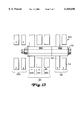
- FIGS. 12 and 13 are partial expanded views of an interconnecting bus bar and offset extension bus bars.
- FIG. 1 illustrates a simplified, partial cross-sectional view of a prior art electric traction vehicle 10 illustrated as a locomotive. Although a locomotive is shown in FIGS. 1 and 2, the present invention is also applicable to traction systems wherein power is received from an external power generation source and distributed via a catenary or third rail.
- the locomotive 10 of FIG. 1 includes a plurality of traction motors, not visible in the figure but located behind the drive wheels 12 and coupled in driving relationship to axles 14.
- the motors are preferably alternating current (AC) electric motors and the locomotive includes a plurality of electrical inverter circuits for controlling electrical power to the motors.
- AC alternating current
- FIG. 2 illustrates a simplified schematic representation of the electrical traction system for locomotive 10 including an alternator 16 driven by an on-board internal combustion engine such as a diesel engine (not shown). Power output of the alternator 16 is regulated in a well known manner by field excitation control indicated by block 18. Electrical power from alternator 16 is rectified, block 20, and coupled to inverters 22. Inverters 22 use high power semiconductor switching devices such as IGBTs or GTOs to convert the rectified power to variable frequency, variable amplitude power for application to AC motors 24.
- IGBTs or GTOs high power semiconductor switching devices
- electrical power circuits are at least partially located in equipment compartment 26.
- the high power semiconductor devices (not shown in FIG. 1) are mounted to air cooled heat sinks 36 which may be attached in cantilever fashion to equipment wall 32 and are generally hollow.
- the heat sinks are sealingly mounted to apertures 31 extending through wall 32.
- the control electronics for the inverters 22 and field control 18 as well as other electronic components are packaged in a conventional manner on circuit boards held in racks in compartment 26.
- Mounted outside compartment 26 are one or more blowers (now shown) which provide air cooling for the electrical compartment and the heat sinks.
- FIG. 3 is a circuit diagram of a prior art power inverter 310
- FIG. 4 is a top view of a one potential low to medium power circuit layout of the circuit of FIG. 3
- FIG. 5 is a sectional side view along line 5--5 of FIG. 4.
- a common design for low to medium power inverters includes a single five layer bus structure 330 for all three phases which interconnects six insulated gate bipolar transistor (IGBT) modules 312 and several DC link capacitors 314. In the event of a failure in an IGBT module, the entire inverter must be removed. For repair, the bus bar must be disconnected from all six IGBT modules and the DC link capacitors before a failed IGBT module can be replaced.
- IGBT insulated gate bipolar transistor
- FIG. 6 is a circuit diagram of one phase of a prior art high power inverter 320
- FIG. 7 is a top view of a circuit layout of the circuit of FIG. 6.
- a single phase assembly generally includes two coupled IGBT modules 322 with the collector of one module connected to the positive DC bus 321 and the emitter of the other module connected to the negative DC bus 323.
- An additional bus bar is used to connect bus bars of three single phase assemblies to provide three phase power.
- the pair of IGBT modules 322 and typically the local DC link capacitor 324 need to be removed.
- a single phase assembly is removable without removing the other two phases, for high power inverters the removable section is larger and heavier than desired.
- FIG. 8 is a perspective view of a modular bus bar and switch assembly 110 of the present invention
- FIG. 9 is a top view of the assembly of FIG. 8. Because inductance is proportional to the area between the bus bar conductors and inversely proportional to the width of the conductive interconnections, the total amount of area between bus bar conductors should be minimized or kept sufficiently low so as to enable the assembly to operate without a snubber. Inductances less than 1 ⁇ 10 -7 Henries are sufficiently low for high power inverters.
- extension bus bars 132 and 532 which each have a ninety degree bend and are coupled to a vertical interconnecting bus bar 130 with bus bar fasteners 135 and to respective IGBT modules 112 and 512 with IGBT fasteners 134.
- ninety degree angles are shown in FIGS. 8 and 9 for purposes of example, the present invention is not limited by an angle (or lack of an angle) of the extension bus bars.
- An AC connection 136 is situated in the interconnecting bus bar.
- the IGBT module, heat sink, and extension bus bar can be disconnected from the interconnecting bus bar by undoing the bus bar fasteners 135.
- the fasteners comprise bolts. Additional fasteners, shown as bolts 142 in FIG. 9, can be used to couple the heat sink to the IGBT module.
- the DC link capacitors 114 can likewise be positioned with extension bus bars 132 at ninety degree angles with respect to interconnecting bus bar 130.
- gate drives 140 shown in FIG. 9) can additionally be coupled to extension bus bars 132.
- the heat sink fins 119 are shown as extending lengthwise in a direction substantially parallel to that of the interconnecting bus bar 130.
- the heat sink includes a base plate 144 and a substantially closed back surface 145 so that forced air can be directed to enter the heat sink through one open surface 147 and leave through a second open surface 149.
- the back surface can be formed either by a heat sink back cover or by a wall to which the heat sink is mounted.
- FIG. 10 is a top view of another bus bar and switch assembly 210 of the present invention
- FIG. 11 is a sectional side view along line 11--11 of the assembly of FIG. 10.
- extension bus bars 232 instead of being situated at ninety degree angles with respect to a connecting interconnecting bus bar 230, extension bus bars 232 bring electronic switching devices, shown as IGBT modules 212, and their respective heat sinks 218 in planes which are substantially in parallel with each other and with the interconnecting bus bar to reduce the overall width of the inverter (as compared with the embodiment of FIG. 9).
- fins 219 of the heat sinks are situated substantially perpendicular with respect to the interconnecting bus bar 230.
- the heat sink 218 can have a base plate 244 and a back surface 245 with first and second open surfaces 247 and 249 for air flow.
- two air inlets 250 and 252 can be used to direct air through an air duct 251 to the first open surface 247 which then passes through heat sink 218 and out the second open surface 249. If the heat sink is attached to a wall 254 of an electrical circuit area, the air inlets can also be attached to the wall.
- FIGS. 12 and 13 are partial expanded perspective and side views of interconnecting bus bar 130 and offset extension bus bars 132 and 532.
- FIG. 12 shows a useful technique of the present invention for arranging connection bushings to achieve the circuit connections of the switching arrangement shown in FIG. 6 and, for simplicity of illustration, it does not show the fasteners of FIGS. 8-11.
- the view is shown with ninety degree angled extension bus bars for purposes of example only.
- the extension bus bars 132 and 532 may also comprise laminated bus bars with conductor sections defined by an emitter conductor 712 and a collector conductor 714 with an insulating layer (not shown) situated therebetween.
- the conductor sections of the bus bars comprise a metal such as copper.
- the conductor sections of the bus bars further include connection bushings shown as 452 and 454 on the AC line, 456 on the positive bus, 458 and 461 on the negative bus, 460 and 462 on the extension bus bar 532, 442 and 448 on the collector conductor of extension bus bar 132, and 440 and 450 on the emitter conductor of extension bus bar 132, and clearance holes shown as 460, 446, and 444.
- the connection bushings generally comprise metal cylinders machined from a material such as copper and can be brazed to their respective conductor sections.
- the offset can be provided, for example, by using an extension bus bar like 132 with a section 470 adjacent to the interconnecting bus bar and divided into two connection portions 472 and 474 with a clearance area 476 therebetween.
- Connection portion 472 of section 470 includes the collector connection bushing 442 and the emitter connection bushing 440.
- Connection portion 474 includes the emitter connection bushing 450 and the collector connection bushing 448. The positions of the emitter and collector connection bushing of portion 474 are rotated 180 degrees with respect to the positions of the emitter and collector connection bushing of portion 472. Also shown are two clearance holes 446 and 444 situated in clearance area 476.
- FIG. 13 illustrates a fastener comprising a bolt 710 that is applied between interconnecting bus bar connection bushing 461 and extension bus bar connection bushing 440.
- collector connection bushing 442 and emitter connection bushing 440 are coupled to IGBT 112 (the negative switch).
- the collector connection bushing 442 is coupled to the collector connection busing 452 of the AC line (shown along dotted line 414), and the emitter connection bushing is coupled to emitter connection bushing 458 of the negative DC bus (shown along dotted line 410).
- FIGS. 12 and 13 this is shown by the coupling of negative bus bar connection bushing 461 with emitter connection bushing 450 of extension bus bar 132. Having two parallel and redundant connections for each emitter and collector provides lower current per connection bushing and lower total inductance.
- Bus bar 532 can be made identical to bus bar 132.
- the bus bar is applied so that the emitter connection bushing 462 of bus bar 532 is aligned with a centrally located emitter connection bushing 454 of AC line 422 (shown along dotted line 416), and the collector connection bushing 460 of extension bus bar 532 is aligned with the centrally located collector connection bushing 456 of positive DC bus 421 (shown along dotted line 412).
Abstract
Description
Claims (21)
Priority Applications (1)
| Application Number | Priority Date | Filing Date | Title |
|---|---|---|---|
| US09/072,102 US6160696A (en) | 1998-05-04 | 1998-05-04 | Modular bus bar and switch assembly for traction inverter |
Applications Claiming Priority (1)
| Application Number | Priority Date | Filing Date | Title |
|---|---|---|---|
| US09/072,102 US6160696A (en) | 1998-05-04 | 1998-05-04 | Modular bus bar and switch assembly for traction inverter |
Publications (1)
| Publication Number | Publication Date |
|---|---|
| US6160696A true US6160696A (en) | 2000-12-12 |
Family
ID=22105585
Family Applications (1)
| Application Number | Title | Priority Date | Filing Date |
|---|---|---|---|
| US09/072,102 Expired - Lifetime US6160696A (en) | 1998-05-04 | 1998-05-04 | Modular bus bar and switch assembly for traction inverter |
Country Status (1)
| Country | Link |
|---|---|
| US (1) | US6160696A (en) |
Cited By (44)
| Publication number | Priority date | Publication date | Assignee | Title |
|---|---|---|---|---|
| EP1226996A2 (en) * | 2001-01-25 | 2002-07-31 | Mitsubishi Heavy Industries, Ltd. | Motor controller for battery forklift |
| US20030223528A1 (en) * | 1995-06-16 | 2003-12-04 | George Miley | Electrostatic accelerated-recirculating-ion fusion neutron/proton source |
| US6671169B1 (en) * | 1998-11-06 | 2003-12-30 | Rodscha Drabon | Power converter with direct voltage and alternating voltage buses |
| US20040012983A1 (en) * | 2000-11-03 | 2004-01-22 | Smc Electrical Products, Inc. | Microdrive |
| US6814628B2 (en) | 2001-06-27 | 2004-11-09 | Fci Americas Technology, Inc. | Modular lug block assembly |
| WO2004110123A1 (en) * | 2003-06-11 | 2004-12-16 | Compact Dynamics Gmbh | Electronic component for the switching of electrical power |
| US20050122692A1 (en) * | 2001-12-13 | 2005-06-09 | Aloys Wobben | Power inverter |
| US20060002054A1 (en) * | 2004-07-02 | 2006-01-05 | Visteon Global Technologies, Inc. | Electric machine with integrated electronics in a circular/closed-loop arrangement |
| US20060146480A1 (en) * | 2003-11-07 | 2006-07-06 | Maxwell Technologies, Inc. | Self-supporting capacitor structure |
| US20070007829A1 (en) * | 2005-07-09 | 2007-01-11 | Wolfgang Schon | Electric machine with integrated power electronics and method for producing the bond of the DC bars with the DC contacts surfaces of the power semiconductor of the power electronics |
| US20070177334A1 (en) * | 2003-11-07 | 2007-08-02 | Maxwell Technologies, Inc. | Thermal interconnection for capacitor systems |
| US20080246257A1 (en) * | 2007-04-03 | 2008-10-09 | Zf Friedrichshafen Ag | Axle module for a vehicle |
| WO2009008741A1 (en) * | 2007-07-09 | 2009-01-15 | Power Concepts Nz Limited | Layered structure connection and assembly |
| US20090086427A1 (en) * | 2007-09-26 | 2009-04-02 | Rohm Co., Ltd. | Semiconductor device |
| EP2064931A2 (en) * | 2006-09-18 | 2009-06-03 | Voith Turbo GmbH & Co. KG | Electric switching and control device, in particular for locomotives |
| US20090195066A1 (en) * | 2006-06-23 | 2009-08-06 | Mitsubishi Electric Corporation | Power converter |
| US20100038133A1 (en) * | 2008-08-13 | 2010-02-18 | Joseph Matthew Senk | Electrical center with vertical power bus bar |
| US7859826B2 (en) | 2005-03-14 | 2010-12-28 | Maxwell Technologies, Inc. | Thermal interconnects for coupling energy storage devices |
| US20110085363A1 (en) * | 2009-10-14 | 2011-04-14 | Sudhir Kumar Gupta | Power electronics and integration system for providing a common high current inverter for use with a traction inverter and an auxiliary inverter |
| DE102010000082A1 (en) * | 2010-01-14 | 2011-07-21 | Woodward Kempen GmbH, 47906 | Circuit arrangement of electronic circuit breakers of a power generating device |
| KR101109698B1 (en) | 2007-12-27 | 2012-01-31 | 현대중공업 주식회사 | High capacity dummy spring stack for high speed train |
| US20120044640A1 (en) * | 2009-07-06 | 2012-02-23 | Mitsubishi Electric Corporation | Power converter |
| CN101197546B (en) * | 2006-12-07 | 2012-05-09 | 日产自动车株式会社 | Power conversion apparatus and motor drive system |
| WO2012115804A2 (en) * | 2011-02-11 | 2012-08-30 | Deere & Company | Power electronics inverter with capacitor cooling |
| US20120218710A1 (en) * | 2011-02-28 | 2012-08-30 | General Electric Company, A New York Corporation | System and Methods for Improving Power Handling of an Electronic Device |
| US8310831B2 (en) | 2010-05-19 | 2012-11-13 | Hamilton Sundstrand Corporation | Thermal packaging of a motor controller for an auxiliary power unit |
| US20130043071A1 (en) * | 2011-08-17 | 2013-02-21 | General Electric Company | Thermal energy management component and system incorporating the same |
| WO2013101910A1 (en) * | 2011-12-30 | 2013-07-04 | General Electric Company | Failure protection for a power delivery system |
| US20130264891A1 (en) * | 2012-04-06 | 2013-10-10 | Denso Corporation | Power conversion apparatus |
| US8649158B2 (en) * | 2008-10-08 | 2014-02-11 | MTU Aero Engines AG | Capacitor arrangement and method for producing a capacitor arrangement |
| US20140077611A1 (en) * | 2012-09-14 | 2014-03-20 | Henry Todd Young | Capacitor bank, laminated bus, and power supply apparatus |
| US20150090435A1 (en) * | 2013-09-29 | 2015-04-02 | Huawei Technologies Co., Ltd. | Support plateheat dissipation apparatus |
| WO2016094357A1 (en) * | 2014-12-08 | 2016-06-16 | Johnson Controls Technology Company | Structural frame cooling manifold |
| US20160308455A1 (en) * | 2015-04-15 | 2016-10-20 | General Electric Company | Inverter drive system, bus bar and assembly |
| US20170027074A1 (en) * | 2014-10-10 | 2017-01-26 | Fuji Electric Co., Ltd. | Semiconductor device and busbar |
| JP2018082597A (en) * | 2016-11-18 | 2018-05-24 | トヨタ自動車株式会社 | Electric circuit device |
| US20180166995A1 (en) * | 2016-12-14 | 2018-06-14 | Caterpillar Inc. | Inverter assembly for electric power system |
| US10128625B2 (en) | 2014-11-18 | 2018-11-13 | General Electric Company | Bus bar and power electronic device with current shaping terminal connector and method of making a terminal connector |
| US10211755B1 (en) * | 2017-08-11 | 2019-02-19 | Galatech, Inc. | Inverter capacitor with phase-out bus bar |
| US10384548B2 (en) * | 2016-04-28 | 2019-08-20 | Ge Global Sourcing Llc | Systems and methods for a vehicle inverter connection bus |
| US10574151B2 (en) | 2017-08-11 | 2020-02-25 | Galatech, Inc. | Inverter capacitor with phase-out bus bar |
| US10717401B2 (en) | 2017-04-21 | 2020-07-21 | Ford Global Technologies, Llc | Terminal block assembly for electrified vehicles |
| EP2842791B1 (en) * | 2013-08-28 | 2021-08-25 | Hitachi, Ltd. | Power converter |
| US11332087B2 (en) * | 2018-06-04 | 2022-05-17 | Westinghouse Air Brake Technologies Corporation | Phase module assembly of a multi-phase inverter |
Citations (31)
| Publication number | Priority date | Publication date | Assignee | Title |
|---|---|---|---|---|
| US3646400A (en) * | 1970-12-21 | 1972-02-29 | Gen Electric | Air-cooling system for hvdc valve with staggered rectifiers |
| US3842336A (en) * | 1973-10-05 | 1974-10-15 | Oxy Metal Finishing Corp | Balancing assembly for parallelled rectifiers |
| US4015184A (en) * | 1975-11-20 | 1977-03-29 | Clinton Supply Company | Silicon junction diode rectifier power pack |
| US4039921A (en) * | 1975-06-11 | 1977-08-02 | Sony Corporation | Inverter radiation suppression |
| US4458305A (en) * | 1981-05-12 | 1984-07-03 | Lucas Industries Plc | Multi-phase transistor/diode bridge circuit |
| US4460956A (en) * | 1981-06-15 | 1984-07-17 | Mitsubishi Denki Kabushiki Kaisha | Rectifying device |
| US4691274A (en) * | 1986-04-29 | 1987-09-01 | Modular Power Corporation | Modular electronic power supply |
| US4772999A (en) * | 1986-12-16 | 1988-09-20 | Merlin Gerin | Static converter, especially for an uninterruptible electrical power supply system |
| US4872102A (en) * | 1986-04-28 | 1989-10-03 | Dimensions Unlimited, Inc. | D.C. to A.C. inverter having improved structure providing improved thermal dissipation |
| US4884631A (en) * | 1988-03-17 | 1989-12-05 | California Institute Of Technology | Forced air heat sink apparatus |
| US4992925A (en) * | 1988-01-29 | 1991-02-12 | Heidelberger Druckmaschinen Ag | Converter with intermediate d.c. circuit |
| US5132896A (en) * | 1990-03-30 | 1992-07-21 | Mitsubishi Denki K.K. | Inverter unit with improved bus-plate configuration |
| US5170336A (en) * | 1990-03-05 | 1992-12-08 | Dimensions Unlimited, Inc. | DC to AC inverter with improved forced air cooling method and apparatus |
| US5172310A (en) * | 1991-07-10 | 1992-12-15 | U.S. Windpower, Inc. | Low impedance bus for power electronics |
| US5202578A (en) * | 1989-09-11 | 1993-04-13 | Kabushiki Kaisha Toshiba | Module-type semiconductor device of high power capacity |
| US5245527A (en) * | 1991-12-24 | 1993-09-14 | Siemens Electric Limited | Modular ac drive controller |
| US5253613A (en) * | 1992-04-30 | 1993-10-19 | General Electric Company | High power AC traction inverter cooling |
| US5434770A (en) * | 1992-11-20 | 1995-07-18 | United States Department Of Energy | High voltage power supply with modular series resonant inverters |
| US5444295A (en) * | 1993-09-07 | 1995-08-22 | Delco Electronics Corp. | Linear dual switch module |
| US5491370A (en) * | 1994-01-28 | 1996-02-13 | General Motors Corporation | Integrated AC machine |
| US5492842A (en) * | 1994-03-09 | 1996-02-20 | Delco Electronics Corp. | Substrate subassembly and method of making transistor switch module |
| US5493472A (en) * | 1994-02-25 | 1996-02-20 | Electronic Concepts, Inc. | Capacitor module with epoxy housing and terminal mounting inserts |
| US5504378A (en) * | 1994-06-10 | 1996-04-02 | Westinghouse Electric Corp. | Direct cooled switching module for electric vehicle propulsion system |
| US5517063A (en) * | 1994-06-10 | 1996-05-14 | Westinghouse Electric Corp. | Three phase power bridge assembly |
| US5563447A (en) * | 1993-09-07 | 1996-10-08 | Delco Electronics Corp. | High power semiconductor switch module |
| US5565705A (en) * | 1994-05-02 | 1996-10-15 | Motorola, Inc. | Electronic module for removing heat from a semiconductor die |
| US5623399A (en) * | 1994-03-04 | 1997-04-22 | Nippondenso Co., Ltd. | Inverter apparatus having capacitors mounted proximal to associated switching circuits |
| US5631821A (en) * | 1993-12-27 | 1997-05-20 | Hitachi, Ltd. | Cooling system for electric vehicle inverter system |
| US5694312A (en) * | 1992-06-10 | 1997-12-02 | Digital Equipment Corporation | Uninterruptible power supply with fault tolerance in a high voltage environment |
| US5712802A (en) * | 1996-04-16 | 1998-01-27 | General Electric Company | Thermal protection of traction inverters |
| US5936833A (en) * | 1997-05-09 | 1999-08-10 | Abb Daimler-Benz Transportation (Technology) Gmbh | Converter modules having a busbar system for power semiconductor switches |
-
1998
- 1998-05-04 US US09/072,102 patent/US6160696A/en not_active Expired - Lifetime
Patent Citations (32)
| Publication number | Priority date | Publication date | Assignee | Title |
|---|---|---|---|---|
| US3646400A (en) * | 1970-12-21 | 1972-02-29 | Gen Electric | Air-cooling system for hvdc valve with staggered rectifiers |
| US3842336A (en) * | 1973-10-05 | 1974-10-15 | Oxy Metal Finishing Corp | Balancing assembly for parallelled rectifiers |
| US4039921A (en) * | 1975-06-11 | 1977-08-02 | Sony Corporation | Inverter radiation suppression |
| US4015184A (en) * | 1975-11-20 | 1977-03-29 | Clinton Supply Company | Silicon junction diode rectifier power pack |
| US4458305A (en) * | 1981-05-12 | 1984-07-03 | Lucas Industries Plc | Multi-phase transistor/diode bridge circuit |
| US4460956A (en) * | 1981-06-15 | 1984-07-17 | Mitsubishi Denki Kabushiki Kaisha | Rectifying device |
| US4872102A (en) * | 1986-04-28 | 1989-10-03 | Dimensions Unlimited, Inc. | D.C. to A.C. inverter having improved structure providing improved thermal dissipation |
| US4691274A (en) * | 1986-04-29 | 1987-09-01 | Modular Power Corporation | Modular electronic power supply |
| US4772999A (en) * | 1986-12-16 | 1988-09-20 | Merlin Gerin | Static converter, especially for an uninterruptible electrical power supply system |
| US4992925A (en) * | 1988-01-29 | 1991-02-12 | Heidelberger Druckmaschinen Ag | Converter with intermediate d.c. circuit |
| US4884631A (en) * | 1988-03-17 | 1989-12-05 | California Institute Of Technology | Forced air heat sink apparatus |
| US5202578A (en) * | 1989-09-11 | 1993-04-13 | Kabushiki Kaisha Toshiba | Module-type semiconductor device of high power capacity |
| US5170336A (en) * | 1990-03-05 | 1992-12-08 | Dimensions Unlimited, Inc. | DC to AC inverter with improved forced air cooling method and apparatus |
| US5132896A (en) * | 1990-03-30 | 1992-07-21 | Mitsubishi Denki K.K. | Inverter unit with improved bus-plate configuration |
| US5172310A (en) * | 1991-07-10 | 1992-12-15 | U.S. Windpower, Inc. | Low impedance bus for power electronics |
| US5245527A (en) * | 1991-12-24 | 1993-09-14 | Siemens Electric Limited | Modular ac drive controller |
| US5253613A (en) * | 1992-04-30 | 1993-10-19 | General Electric Company | High power AC traction inverter cooling |
| US5694312A (en) * | 1992-06-10 | 1997-12-02 | Digital Equipment Corporation | Uninterruptible power supply with fault tolerance in a high voltage environment |
| US5434770A (en) * | 1992-11-20 | 1995-07-18 | United States Department Of Energy | High voltage power supply with modular series resonant inverters |
| US5444295A (en) * | 1993-09-07 | 1995-08-22 | Delco Electronics Corp. | Linear dual switch module |
| US5563447A (en) * | 1993-09-07 | 1996-10-08 | Delco Electronics Corp. | High power semiconductor switch module |
| US5631821A (en) * | 1993-12-27 | 1997-05-20 | Hitachi, Ltd. | Cooling system for electric vehicle inverter system |
| US5491370A (en) * | 1994-01-28 | 1996-02-13 | General Motors Corporation | Integrated AC machine |
| US5493472A (en) * | 1994-02-25 | 1996-02-20 | Electronic Concepts, Inc. | Capacitor module with epoxy housing and terminal mounting inserts |
| US5623399A (en) * | 1994-03-04 | 1997-04-22 | Nippondenso Co., Ltd. | Inverter apparatus having capacitors mounted proximal to associated switching circuits |
| US5492842A (en) * | 1994-03-09 | 1996-02-20 | Delco Electronics Corp. | Substrate subassembly and method of making transistor switch module |
| US5539254A (en) * | 1994-03-09 | 1996-07-23 | Delco Electronics Corp. | Substrate subassembly for a transistor switch module |
| US5565705A (en) * | 1994-05-02 | 1996-10-15 | Motorola, Inc. | Electronic module for removing heat from a semiconductor die |
| US5517063A (en) * | 1994-06-10 | 1996-05-14 | Westinghouse Electric Corp. | Three phase power bridge assembly |
| US5504378A (en) * | 1994-06-10 | 1996-04-02 | Westinghouse Electric Corp. | Direct cooled switching module for electric vehicle propulsion system |
| US5712802A (en) * | 1996-04-16 | 1998-01-27 | General Electric Company | Thermal protection of traction inverters |
| US5936833A (en) * | 1997-05-09 | 1999-08-10 | Abb Daimler-Benz Transportation (Technology) Gmbh | Converter modules having a busbar system for power semiconductor switches |
Cited By (86)
| Publication number | Priority date | Publication date | Assignee | Title |
|---|---|---|---|---|
| US20030223528A1 (en) * | 1995-06-16 | 2003-12-04 | George Miley | Electrostatic accelerated-recirculating-ion fusion neutron/proton source |
| US6671169B1 (en) * | 1998-11-06 | 2003-12-30 | Rodscha Drabon | Power converter with direct voltage and alternating voltage buses |
| US20040012983A1 (en) * | 2000-11-03 | 2004-01-22 | Smc Electrical Products, Inc. | Microdrive |
| US6822866B2 (en) * | 2000-11-03 | 2004-11-23 | Smc Electrical Products Inc. | Microdrive |
| EP1226996A2 (en) * | 2001-01-25 | 2002-07-31 | Mitsubishi Heavy Industries, Ltd. | Motor controller for battery forklift |
| EP1226996A3 (en) * | 2001-01-25 | 2003-12-17 | Mitsubishi Heavy Industries, Ltd. | Motor controller for battery forklift |
| US6814628B2 (en) | 2001-06-27 | 2004-11-09 | Fci Americas Technology, Inc. | Modular lug block assembly |
| US20050122692A1 (en) * | 2001-12-13 | 2005-06-09 | Aloys Wobben | Power inverter |
| US7492621B2 (en) | 2001-12-13 | 2009-02-17 | Aloys Wobben | Inverter, method for use thereof and wind power installation employing same |
| WO2004110123A1 (en) * | 2003-06-11 | 2004-12-16 | Compact Dynamics Gmbh | Electronic component for the switching of electrical power |
| US7760480B2 (en) * | 2003-06-11 | 2010-07-20 | Compact Dynamics Gmbh | Electronic assembly for switching electric power |
| US20060209494A1 (en) * | 2003-06-11 | 2006-09-21 | Andreas Grundl | Electronic assembly for switching electric power |
| US20060146480A1 (en) * | 2003-11-07 | 2006-07-06 | Maxwell Technologies, Inc. | Self-supporting capacitor structure |
| US7180726B2 (en) * | 2003-11-07 | 2007-02-20 | Maxwell Technologies, Inc. | Self-supporting capacitor structure |
| US20070139863A1 (en) * | 2003-11-07 | 2007-06-21 | Maxwell Technologies, Inc. | Self-supporting capacitor structure |
| US20070177334A1 (en) * | 2003-11-07 | 2007-08-02 | Maxwell Technologies, Inc. | Thermal interconnection for capacitor systems |
| US20070177335A1 (en) * | 2003-11-07 | 2007-08-02 | Maxwell Technologies, Inc. | Thermal interconnection for capacitor systems |
| US7511942B2 (en) | 2003-11-07 | 2009-03-31 | Maxwell Technologies, Inc. | Thermal interconnection for capacitor systems |
| US7180212B2 (en) | 2004-07-02 | 2007-02-20 | Visteon Global Technologies, Inc. | Electric machine with integrated electronics in a circular/closed-loop arrangement |
| US20060002054A1 (en) * | 2004-07-02 | 2006-01-05 | Visteon Global Technologies, Inc. | Electric machine with integrated electronics in a circular/closed-loop arrangement |
| US7859826B2 (en) | 2005-03-14 | 2010-12-28 | Maxwell Technologies, Inc. | Thermal interconnects for coupling energy storage devices |
| US7557477B2 (en) * | 2005-07-09 | 2009-07-07 | Zf Friedrichshafen Ag | Electric machine with integrated power electronics and method for producing the bond of the DC bars with the DC contacts surfaces of the power semiconductor of the power electronics |
| US20070007829A1 (en) * | 2005-07-09 | 2007-01-11 | Wolfgang Schon | Electric machine with integrated power electronics and method for producing the bond of the DC bars with the DC contacts surfaces of the power semiconductor of the power electronics |
| US20090195066A1 (en) * | 2006-06-23 | 2009-08-06 | Mitsubishi Electric Corporation | Power converter |
| EP2064931A2 (en) * | 2006-09-18 | 2009-06-03 | Voith Turbo GmbH & Co. KG | Electric switching and control device, in particular for locomotives |
| CN101197546B (en) * | 2006-12-07 | 2012-05-09 | 日产自动车株式会社 | Power conversion apparatus and motor drive system |
| US20080246257A1 (en) * | 2007-04-03 | 2008-10-09 | Zf Friedrichshafen Ag | Axle module for a vehicle |
| US8351216B2 (en) | 2007-07-09 | 2013-01-08 | Power Concepts Nz Limited | Layered structure connection and assembly |
| WO2009008741A1 (en) * | 2007-07-09 | 2009-01-15 | Power Concepts Nz Limited | Layered structure connection and assembly |
| US20100195301A1 (en) * | 2007-07-09 | 2010-08-05 | Christopher William Fotherby | Layered Structure Connection and Assembly |
| US7864533B2 (en) | 2007-09-26 | 2011-01-04 | Rohm Co., Ltd. | Semiconductor device |
| US9379634B2 (en) | 2007-09-26 | 2016-06-28 | Rohm Co., Ltd. | Semiconductor device |
| US8971044B2 (en) | 2007-09-26 | 2015-03-03 | Rohm Co., Ltd. | Semiconductor device |
| US20090086427A1 (en) * | 2007-09-26 | 2009-04-02 | Rohm Co., Ltd. | Semiconductor device |
| US20100265664A1 (en) * | 2007-09-26 | 2010-10-21 | Rohm Co., Ltd. | Semiconductor Device |
| US7773381B2 (en) * | 2007-09-26 | 2010-08-10 | Rohm Co., Ltd. | Semiconductor device |
| US8208260B2 (en) | 2007-09-26 | 2012-06-26 | Rohm Co., Ltd. | Semiconductor device |
| KR101109698B1 (en) | 2007-12-27 | 2012-01-31 | 현대중공업 주식회사 | High capacity dummy spring stack for high speed train |
| US20100038133A1 (en) * | 2008-08-13 | 2010-02-18 | Joseph Matthew Senk | Electrical center with vertical power bus bar |
| US8027168B2 (en) * | 2008-08-13 | 2011-09-27 | Delphi Technologies, Inc. | Electrical center with vertical power bus bar |
| US8649158B2 (en) * | 2008-10-08 | 2014-02-11 | MTU Aero Engines AG | Capacitor arrangement and method for producing a capacitor arrangement |
| US20120044640A1 (en) * | 2009-07-06 | 2012-02-23 | Mitsubishi Electric Corporation | Power converter |
| US8599554B2 (en) * | 2009-07-06 | 2013-12-03 | Mitsubishi Electric Corporation | Power converter |
| US8644044B2 (en) | 2009-10-14 | 2014-02-04 | General Electric Company | Power electronics and integration system for providing a common high current inverter for use with a traction inverter and an auxiliary inverter |
| US20110085363A1 (en) * | 2009-10-14 | 2011-04-14 | Sudhir Kumar Gupta | Power electronics and integration system for providing a common high current inverter for use with a traction inverter and an auxiliary inverter |
| DE102010000082A1 (en) * | 2010-01-14 | 2011-07-21 | Woodward Kempen GmbH, 47906 | Circuit arrangement of electronic circuit breakers of a power generating device |
| DE102010000082B4 (en) * | 2010-01-14 | 2012-10-11 | Woodward Kempen Gmbh | Circuit arrangement of electronic circuit breakers of a power generating device |
| US9673804B2 (en) | 2010-01-14 | 2017-06-06 | Woodward Kempen Gmbh | Circuit arrangement of electronic circuit breakers of a power generation device |
| US8310831B2 (en) | 2010-05-19 | 2012-11-13 | Hamilton Sundstrand Corporation | Thermal packaging of a motor controller for an auxiliary power unit |
| US8780557B2 (en) | 2011-02-11 | 2014-07-15 | Deere & Company | Power electronics inverter with capacitor cooling |
| WO2012115804A3 (en) * | 2011-02-11 | 2014-01-30 | Deere & Company | Power electronics inverter with capacitor cooling |
| WO2012115804A2 (en) * | 2011-02-11 | 2012-08-30 | Deere & Company | Power electronics inverter with capacitor cooling |
| CN103718383A (en) * | 2011-02-11 | 2014-04-09 | 迪尔公司 | Power electronics inverter with capacitor cooling |
| US20120218710A1 (en) * | 2011-02-28 | 2012-08-30 | General Electric Company, A New York Corporation | System and Methods for Improving Power Handling of an Electronic Device |
| US8625283B2 (en) * | 2011-02-28 | 2014-01-07 | General Electric Company | System and methods for improving power handling of an electronic device |
| US20130043071A1 (en) * | 2011-08-17 | 2013-02-21 | General Electric Company | Thermal energy management component and system incorporating the same |
| JP2015503898A (en) * | 2011-12-30 | 2015-02-02 | ゼネラル・エレクトリック・カンパニイ | Damage protection for power supply systems |
| AU2017200827B2 (en) * | 2011-12-30 | 2018-07-26 | Ge Global Sourcing Llc | Failure protection for a power delivery system |
| WO2013101910A1 (en) * | 2011-12-30 | 2013-07-04 | General Electric Company | Failure protection for a power delivery system |
| US20140354042A1 (en) * | 2011-12-30 | 2014-12-04 | Gemeral Electric Company | Failure protection for a power delivery system |
| US20130264891A1 (en) * | 2012-04-06 | 2013-10-10 | Denso Corporation | Power conversion apparatus |
| US9306445B2 (en) * | 2012-04-06 | 2016-04-05 | Denso Corporation | Power conversion apparatus |
| US20140077611A1 (en) * | 2012-09-14 | 2014-03-20 | Henry Todd Young | Capacitor bank, laminated bus, and power supply apparatus |
| EP2842791B1 (en) * | 2013-08-28 | 2021-08-25 | Hitachi, Ltd. | Power converter |
| US20150090435A1 (en) * | 2013-09-29 | 2015-04-02 | Huawei Technologies Co., Ltd. | Support plateheat dissipation apparatus |
| US11604035B2 (en) * | 2013-09-29 | 2023-03-14 | Huawei Technologies Co., Ltd. | Support plateheat dissipation apparatus |
| US9967991B2 (en) * | 2014-10-10 | 2018-05-08 | Fuji Electric Co., Ltd. | Semiconductor device and busbar |
| US20170027074A1 (en) * | 2014-10-10 | 2017-01-26 | Fuji Electric Co., Ltd. | Semiconductor device and busbar |
| US10128625B2 (en) | 2014-11-18 | 2018-11-13 | General Electric Company | Bus bar and power electronic device with current shaping terminal connector and method of making a terminal connector |
| US9654017B2 (en) | 2014-12-08 | 2017-05-16 | Johnson Controls Technology Company | Structural frame cooling manifold |
| KR20160144417A (en) * | 2014-12-08 | 2016-12-16 | 존슨 컨트롤스 테크놀러지 컴퍼니 | Structural frame cooling manifold |
| US10462942B2 (en) | 2014-12-08 | 2019-10-29 | Johnson Controls Technology Company | Structural frame cooling manifold |
| WO2016094357A1 (en) * | 2014-12-08 | 2016-06-16 | Johnson Controls Technology Company | Structural frame cooling manifold |
| US10454349B2 (en) * | 2015-04-15 | 2019-10-22 | Ge Global Sourcing Llc | Inverter drive system, bus bar and assembly |
| CN110053633A (en) * | 2015-04-15 | 2019-07-26 | 通用电气全球采购有限责任公司 | Inverter drive system, busbar and component |
| CN110053633B (en) * | 2015-04-15 | 2021-02-09 | 通用电气全球采购有限责任公司 | Inverter drive system, bus bar and assembly |
| US11264871B2 (en) | 2015-04-15 | 2022-03-01 | Transportation Ip Holdings, Llc | Inverter drive system, bus bar and assembly |
| US20160308455A1 (en) * | 2015-04-15 | 2016-10-20 | General Electric Company | Inverter drive system, bus bar and assembly |
| US10384548B2 (en) * | 2016-04-28 | 2019-08-20 | Ge Global Sourcing Llc | Systems and methods for a vehicle inverter connection bus |
| JP2018082597A (en) * | 2016-11-18 | 2018-05-24 | トヨタ自動車株式会社 | Electric circuit device |
| US10291145B2 (en) * | 2016-12-14 | 2019-05-14 | Caterpillar Inc. | Inverter assembly for electric power system |
| US20180166995A1 (en) * | 2016-12-14 | 2018-06-14 | Caterpillar Inc. | Inverter assembly for electric power system |
| US10717401B2 (en) | 2017-04-21 | 2020-07-21 | Ford Global Technologies, Llc | Terminal block assembly for electrified vehicles |
| US10211755B1 (en) * | 2017-08-11 | 2019-02-19 | Galatech, Inc. | Inverter capacitor with phase-out bus bar |
| US10574151B2 (en) | 2017-08-11 | 2020-02-25 | Galatech, Inc. | Inverter capacitor with phase-out bus bar |
| US11332087B2 (en) * | 2018-06-04 | 2022-05-17 | Westinghouse Air Brake Technologies Corporation | Phase module assembly of a multi-phase inverter |
Similar Documents
| Publication | Publication Date | Title |
|---|---|---|
| US6160696A (en) | Modular bus bar and switch assembly for traction inverter | |
| US6233149B1 (en) | High power inverter air cooling | |
| US11264871B2 (en) | Inverter drive system, bus bar and assembly | |
| EP0592661B1 (en) | High power ac traction inverter cooling | |
| JP3563038B2 (en) | Power converter | |
| EP0794098B1 (en) | Electric power transforming apparatus for electric rolling stock | |
| US11452227B2 (en) | Power phase module of a converter, converter, and vehicle | |
| CN1042181C (en) | Inverter apparatus | |
| CN1036749C (en) | Inverter apparatus for electric rolling stock | |
| AU2017200827B2 (en) | Failure protection for a power delivery system | |
| US5164624A (en) | Modular power semiconductor assembly for an alternator-fed DC power source | |
| JP2006149199A (en) | Power conversion apparatus for rail vehicle | |
| US20230301008A1 (en) | Switch module for an inverter, inverter with several such switch modules and vehicle with the inverter | |
| JPWO2009040933A1 (en) | Power converter | |
| JP3822612B2 (en) | Railway vehicle power converter | |
| JP3271059B2 (en) | Three-phase inverter for electric vehicles | |
| JP2004336845A (en) | Onboard power converter | |
| US20240072708A1 (en) | Inverter structure of an inverter of a power electronics module for operating an electric drive of a motor vehicle | |
| CN112172843B (en) | Inverter driving assembly and bus bar for inverter driving assembly of vehicle | |
| JP4020833B2 (en) | Power converter for vehicle | |
| JP3799352B2 (en) | Power converter | |
| US20240049417A1 (en) | Inverter structure of an inverter of a power electronics module for operating an electric drive of a motor vehicle |
Legal Events
| Date | Code | Title | Description |
|---|---|---|---|
| AS | Assignment |
Owner name: GENERAL ELECTRIC COMPANY, NEW YORK Free format text: ASSIGNMENT OF ASSIGNORS INTEREST;ASSIGNORS:BAILEY, RONALD BARRY;IOANNIDIS, DIMITRIOS;REEL/FRAME:009193/0687 Effective date: 19980430 |
|
| STCF | Information on status: patent grant |
Free format text: PATENTED CASE |
|
| FEPP | Fee payment procedure |
Free format text: PAYOR NUMBER ASSIGNED (ORIGINAL EVENT CODE: ASPN); ENTITY STATUS OF PATENT OWNER: LARGE ENTITY |
|
| REMI | Maintenance fee reminder mailed | ||
| FPAY | Fee payment |
Year of fee payment: 4 |
|
| SULP | Surcharge for late payment | ||
| FPAY | Fee payment |
Year of fee payment: 8 |
|
| FPAY | Fee payment |
Year of fee payment: 12 |
|
| AS | Assignment |
Owner name: GE GLOBAL SOURCING LLC, CONNECTICUT Free format text: ASSIGNMENT OF ASSIGNORS INTEREST;ASSIGNOR:GENERAL ELECTRIC COMPANY;REEL/FRAME:047736/0178 Effective date: 20181101 |