US6160915A - Coded signal transmission method and apparatus - Google Patents

Coded signal transmission method and apparatus Download PDF

Info

Publication number
US6160915A
US6160915A US08/958,589 US95858997A US6160915A US 6160915 A US6160915 A US 6160915A US 95858997 A US95858997 A US 95858997A US 6160915 A US6160915 A US 6160915A
Authority
US
United States
Prior art keywords
bit rate
buffer
time
size
picture
Prior art date
Legal status (The legal status is an assumption and is not a legal conclusion. Google has not performed a legal analysis and makes no representation as to the accuracy of the status listed.)
Expired - Lifetime
Application number
US08/958,589
Inventor
Motoki Kato
Hideki Koyanagi
Current Assignee (The listed assignees may be inaccurate. Google has not performed a legal analysis and makes no representation or warranty as to the accuracy of the list.)
Sony Corp
Original Assignee
Sony Corp
Priority date (The priority date is an assumption and is not a legal conclusion. Google has not performed a legal analysis and makes no representation as to the accuracy of the date listed.)
Filing date
Publication date
Application filed by Sony Corp filed Critical Sony Corp
Assigned to SONY CORPORATION reassignment SONY CORPORATION ASSIGNMENT OF ASSIGNORS INTEREST (SEE DOCUMENT FOR DETAILS). Assignors: KATO, MOTOKI, KOYANAGI, HIDEKI
Application granted granted Critical
Publication of US6160915A publication Critical patent/US6160915A/en
Anticipated expiration legal-status Critical
Expired - Lifetime legal-status Critical Current

Links

Images

Classifications

    • HELECTRICITY
    • H04ELECTRIC COMMUNICATION TECHNIQUE
    • H04NPICTORIAL COMMUNICATION, e.g. TELEVISION
    • H04N21/00Selective content distribution, e.g. interactive television or video on demand [VOD]
    • H04N21/20Servers specifically adapted for the distribution of content, e.g. VOD servers; Operations thereof
    • H04N21/23Processing of content or additional data; Elementary server operations; Server middleware
    • H04N21/234Processing of video elementary streams, e.g. splicing of video streams, manipulating MPEG-4 scene graphs
    • H04N21/23406Processing of video elementary streams, e.g. splicing of video streams, manipulating MPEG-4 scene graphs involving management of server-side video buffer
    • HELECTRICITY
    • H04ELECTRIC COMMUNICATION TECHNIQUE
    • H04NPICTORIAL COMMUNICATION, e.g. TELEVISION
    • H04N19/00Methods or arrangements for coding, decoding, compressing or decompressing digital video signals
    • H04N19/10Methods or arrangements for coding, decoding, compressing or decompressing digital video signals using adaptive coding
    • H04N19/102Methods or arrangements for coding, decoding, compressing or decompressing digital video signals using adaptive coding characterised by the element, parameter or selection affected or controlled by the adaptive coding
    • H04N19/115Selection of the code volume for a coding unit prior to coding
    • HELECTRICITY
    • H04ELECTRIC COMMUNICATION TECHNIQUE
    • H04NPICTORIAL COMMUNICATION, e.g. TELEVISION
    • H04N19/00Methods or arrangements for coding, decoding, compressing or decompressing digital video signals
    • H04N19/10Methods or arrangements for coding, decoding, compressing or decompressing digital video signals using adaptive coding
    • H04N19/134Methods or arrangements for coding, decoding, compressing or decompressing digital video signals using adaptive coding characterised by the element, parameter or criterion affecting or controlling the adaptive coding
    • H04N19/146Data rate or code amount at the encoder output
    • H04N19/152Data rate or code amount at the encoder output by measuring the fullness of the transmission buffer
    • HELECTRICITY
    • H04ELECTRIC COMMUNICATION TECHNIQUE
    • H04NPICTORIAL COMMUNICATION, e.g. TELEVISION
    • H04N19/00Methods or arrangements for coding, decoding, compressing or decompressing digital video signals
    • H04N19/10Methods or arrangements for coding, decoding, compressing or decompressing digital video signals using adaptive coding
    • H04N19/134Methods or arrangements for coding, decoding, compressing or decompressing digital video signals using adaptive coding characterised by the element, parameter or criterion affecting or controlling the adaptive coding
    • H04N19/164Feedback from the receiver or from the transmission channel
    • HELECTRICITY
    • H04ELECTRIC COMMUNICATION TECHNIQUE
    • H04NPICTORIAL COMMUNICATION, e.g. TELEVISION
    • H04N19/00Methods or arrangements for coding, decoding, compressing or decompressing digital video signals
    • H04N19/10Methods or arrangements for coding, decoding, compressing or decompressing digital video signals using adaptive coding
    • H04N19/169Methods or arrangements for coding, decoding, compressing or decompressing digital video signals using adaptive coding characterised by the coding unit, i.e. the structural portion or semantic portion of the video signal being the object or the subject of the adaptive coding
    • H04N19/184Methods or arrangements for coding, decoding, compressing or decompressing digital video signals using adaptive coding characterised by the coding unit, i.e. the structural portion or semantic portion of the video signal being the object or the subject of the adaptive coding the unit being bits, e.g. of the compressed video stream
    • HELECTRICITY
    • H04ELECTRIC COMMUNICATION TECHNIQUE
    • H04NPICTORIAL COMMUNICATION, e.g. TELEVISION
    • H04N19/00Methods or arrangements for coding, decoding, compressing or decompressing digital video signals
    • H04N19/60Methods or arrangements for coding, decoding, compressing or decompressing digital video signals using transform coding
    • H04N19/61Methods or arrangements for coding, decoding, compressing or decompressing digital video signals using transform coding in combination with predictive coding
    • HELECTRICITY
    • H04ELECTRIC COMMUNICATION TECHNIQUE
    • H04NPICTORIAL COMMUNICATION, e.g. TELEVISION
    • H04N21/00Selective content distribution, e.g. interactive television or video on demand [VOD]
    • H04N21/40Client devices specifically adapted for the reception of or interaction with content, e.g. set-top-box [STB]; Operations thereof
    • H04N21/43Processing of content or additional data, e.g. demultiplexing additional data from a digital video stream; Elementary client operations, e.g. monitoring of home network or synchronising decoder's clock; Client middleware
    • H04N21/44Processing of video elementary streams, e.g. splicing a video clip retrieved from local storage with an incoming video stream, rendering scenes according to MPEG-4 scene graphs
    • H04N21/44004Processing of video elementary streams, e.g. splicing a video clip retrieved from local storage with an incoming video stream, rendering scenes according to MPEG-4 scene graphs involving video buffer management, e.g. video decoder buffer or video display buffer
    • HELECTRICITY
    • H04ELECTRIC COMMUNICATION TECHNIQUE
    • H04NPICTORIAL COMMUNICATION, e.g. TELEVISION
    • H04N19/00Methods or arrangements for coding, decoding, compressing or decompressing digital video signals
    • H04N19/10Methods or arrangements for coding, decoding, compressing or decompressing digital video signals using adaptive coding
    • H04N19/134Methods or arrangements for coding, decoding, compressing or decompressing digital video signals using adaptive coding characterised by the element, parameter or criterion affecting or controlling the adaptive coding
    • H04N19/146Data rate or code amount at the encoder output
    • H04N19/149Data rate or code amount at the encoder output by estimating the code amount by means of a model, e.g. mathematical model or statistical model
    • HELECTRICITY
    • H04ELECTRIC COMMUNICATION TECHNIQUE
    • H04NPICTORIAL COMMUNICATION, e.g. TELEVISION
    • H04N19/00Methods or arrangements for coding, decoding, compressing or decompressing digital video signals
    • H04N19/10Methods or arrangements for coding, decoding, compressing or decompressing digital video signals using adaptive coding
    • H04N19/134Methods or arrangements for coding, decoding, compressing or decompressing digital video signals using adaptive coding characterised by the element, parameter or criterion affecting or controlling the adaptive coding
    • H04N19/146Data rate or code amount at the encoder output
    • H04N19/15Data rate or code amount at the encoder output by monitoring actual compressed data size at the memory before deciding storage at the transmission buffer

Definitions

  • the present invention relates to a coded signal transmission method and apparatus which can be used for encoding a digital signal at a variable bit rate at a transmission side and transmitting the signal to a reception side.
  • an animation is a dynamic image which changes according a time lapse.
  • a picture movement may greatly differ in the center and in the periphery of the image.
  • the data amount generated when encoded by an encoder varies depending on the property of the image.
  • a transmission buffer is provided at the last stage of an encoder system. That is, The encoded data changing in the amount generated is temporarily stored in the transmission buffer, from where the data is read out at a predetermined transmission bit rate and output to a transmission line.
  • FIG. 1 is a block diagram of a conventional encoder (hereinafter, referred to as an encoder system) having a constant output bit rate.
  • an encoder buffer 13 is provided between a transmission line and a video encoder 12 which is supplied with a video input through a terminal 11, for controlling the smoothing of the fluctuation of the bit amounts generated in a short period of time from the video encoder 12 so that the encoder buffer 13 can output a bit stream at a constant bit rate.
  • a rate controller 15 is supplied with an encoded picture generation bit amount S21 from the video encoder 12, a bit rate R from a terminal 16, and a decoder buffer size B from a terminal 10, and calculates a bit amount S22 to be assigned for the following picture to be encoded so as not to overflow or underflow the decoder buffer of the aforementioned size B, for example, according to a VBV (Video Buffering Verifier) model which will be detailed later. Data on the bit amount S22 calculated is transmitted to the video encoder 12 for specification.
  • VBV Video Buffering Verifier
  • the encoder buffer 13 is supplied with a video bit stream from the video encoder 12 and has a code buffer at least equal to the decoder buffer size B. Normally, the code buffer is included in the transmission buffer.
  • the bit stream outputted from the encoder buffer 13 is supplied to a multiplexer 14.
  • the multiplexer 14 is also supplied with an encoded bit stream of an audio signal.
  • a plurality of input bit streams are system-encoded and multiplexed, and the multiplexed stream is outputted from a terminal 17.
  • a start of output of the bit stream from the encoder buffer is specified by a start controller 19. This is illustrated in FIG. 1 in such a configuration that the start controller 19 controls a switch 20 provided at the output side of the encoder buffer 13.
  • the start time is calculated, as will be detailed later, according to the aforementioned bit rate R and a data supplied from a terminal 18 on bit occupation amount b0 at a decoding start moment of the decoder buffer.
  • FIG. 2 is a block diagram of a conventional decoder (hereinafter, referred to a decoder system).
  • a demultiplexer 26 is supplied with the multiplexed stream from a terminal 25.
  • the video stream which has been isolated by the demultiplexer 26 is stored in a reception buffer (hereinafter, referred to as a decoder buffer) 27.
  • the decoder buffer 27 serves to absorb a fluctuation of the bit amount which is read out by the video decoder 28 during a short period of time. Because the decoder system is a passive system for the bit stream supplied, in order to enable stable video reproduction by the video decoder 28, the encoder system should carry out encoding while controlling not to cause overflow or underflow of the decoder buffer 27.
  • the MPEG is an abbreviation of the Moving Picture Coding Experts Group for examination of animation encoding for storage, which group belongs to the ISO/JTC1/SC29 (International Organization for Standardization/ International Electrotechnical Commission, Joint Technical Committee 1/ Sub Committee 29).
  • the MPEG1 Standard is the ISO11172 and the MPEG2 Standard is the ISO13818.
  • ISO11172-1 and ISO13818-1 are items for multimedia multiplexing
  • ISO11172-2 and ISO13818-2 are items for images
  • ISO11172-3 and ISO13818-3 are items for voice.
  • This MPEG standard assumes an ideal I/O model of the decoder buffer 27 of the decoder system, and specifies an encoder system which carries out encoding while controlling not to overflow or underflow the decoder buffer 27, assuming the decoder buffer model (an ideal model of the decoder buffer).
  • the I/O model of the decoder buffer 27 of the decoder system is described as VBV (Video Buffering Verifier) in the ISO/IEC 11172-2 Annex C or ISO/IEC 13818-2 Annex C.
  • the VBV buffer size of the decoder system is specified by the identifier "vbv -- buffer -- size" in the MPEG bit stream.
  • the typical size for example, is 1.75M bits at MP@ (Main Profile at Main Level)
  • VBV of the decoder system is assumed to operate under the following ideal condition.
  • a bit stream corresponding to a picture is instantaneously outputted from the decoder buffer and each of the pictures is decoded instantaneously.
  • the transmission buffer (encoder buffer) of the encoder system should operate under the following ideal condition.
  • FIG. 3 shows an example of changes of the bit occupation amount of the buffers in the encoder system and the decoder system according to the VBV mode.
  • a straight line c-d divides the encoder system and the decoder system. That is, the change of bit occupation amount in the decoder buffer is shown at the right side of line c-d, and the change of bit occupation amount in the encoder buffer is shown at the left side of the line c-d.
  • the two of the horizontal axes t represent the time lapses: the upper time axis represents a time lapse in the encoder system and the lower time axis represents a time lapse in the decoder system.
  • the line c-d is shared by the encoder system and the decoder system as if there were no time difference between them.
  • the D0 includes the processing time of the multiplexer 14 in the encoder system, the transmission time, and the processing time of the demultiplexer 26 in the decoder system.
  • the vertical axis represents, in the encoder system, the accumulated bit amount of the bit stream outputted from the encoder buffer at a particular time, and in the decoder system, the accumulated bit amount of the bit stream inputted to the decoder buffer at a particular time.
  • the slope of the line c-d ( ⁇ d/ ⁇ t) can be viewed from the encoder system as a constant output bit rate R from the encoder buffer 13 and from the decoder system as a constant input rate R to the decoder buffer 27.
  • the vertical distance between the line c-d and the line e-f along the vertical axis represents a size B of the decoder buffer.
  • the vertical distance between the line c-d and the line a-b represents a size B of the encoder buffer.
  • the B is a constant value.
  • the size of the encoder system is always identical to the size of the decoder system.
  • the A(n) represents an n-th coded picture, and its size represents the bit amount of the coded picture.
  • each of the pictures is encoded as an I picture, P picture, or B picture.
  • the I picture is encoded by using its own image signal alone.
  • the P picture is motion-compensative-predicted from an I picture or P picture immediately before and the prediction residue is coded.
  • the B picture is motion-compensative-predicted from an I picture or P picture immediately before and immediately after, and the prediction residue is coded.
  • the bit amount of each coded picture A(n) changes according to the picture type I, P, or B and the picture content.
  • the ETS(n) represents a time to encode the coded picture A(n).
  • the interval of pictures to be encoded i.e., ETS(n+1) -ETS(n)
  • the DTS(n) represents a time to decode the n-th coded picture A(n).
  • the interval of pictures to be decoded i.e., DTS(n+1)-DTS(n) is identical to the interval of pictures to be encoded.
  • the region below the stepped zigzag trace in the figure represents the bit occupation amount change in the encode buffer. That is, the vertical distance from the time t on the line c-d to the stepped trace represents the bit occupation amount at time t.
  • the vertical direction movement of the stepped trace represents an instantaneous input of a bit stream from the video encoder 12 to the encoder buffer 13, whereas the horizontal direction movement of the stepped trace indicates that no bit stream is inputted from the video encoder 12 to the encoder buffer 13 (no encoding is carried out), and the encoder buffer 13 outputs a bit stream at the bit rate R.
  • the bit occupation amount in the encoder buffer is zero.
  • the start is specified by the start controller 19 in the encoder system shown in FIG. 4. This start time do is calculated from the bit rate R and the bit occupation amount b0 at the decoding start of the decoder buffer as follows.
  • a bit stream is outputted from the encoder buffer at the bit rate R, which decreases the bit occupation amount of the encoder buffer as the time lapses.
  • the 1-st picture A(1) is encoded and supplied to the encoder buffer, which instantaneously increases the bit occupation amount of the encoder buffer by the bit amount of the 1-st picture A(1).
  • a bit stream is outputted from the encoder buffer at the bit rate R, which decreases the bit occupation amount of the encoder buffer as the time lapses.
  • picture encoding is continued at a predetermined time interval.
  • the bit occupation amount in the decoder buffer is changed according to the bit occupation amount change of the aforementioned encoder buffer.
  • the region above the stepped trace represents the bit occupation amount change. That is, the vertical distance from the time t on the line c-d to the stepped trace along the vertical axis represents the bit occupation amount of the decoder buffer at time t.
  • the vertical direction movement of the stepped trace represents that the video decoder 28 instantaneously reads out a bit stream from the decoder buffer 27, whereas the horizontal direction movement of the stepped trace represents that the video decoder 28 reads out no bit stream from the decoder buffer 27 (no decoding is carried out) and a bit stream is inputted to this decoder buffer 27 at the bit rate R.
  • the time duration di i.e.,
  • This moment of time di or time DTS(0) is specified by the bit stream received.
  • the bit occupation amount of the decoder buffer is instantaneously decreased by decoding the 0-th coded picture A(0) at time DTS by the bit amount of the aforementioned 0-th coded picture A(0).
  • a bit stream is inputted to the decoder buffer at the bit rate R, which increases the bit occupation amount of the decoder buffer as the time lapses.
  • the 1-st coded picture A(1) is decoded, which instantaneously decreases the bit occupation amount of the decoder buffer by the bit amount of the 1-st coded picture A(1).
  • picture decoding is continued at a predetermined time interval.
  • T(i) represents a time interval (hereinafter, T will be referred to as a delay time) from the time ETS(i) when the i-th coded picture A(i) is encoded to the time DES(i) when the i-th coded picture A(i) is decoded. That is,
  • the aforementioned delay time T(i) should be a constant value for encoding/decoding of all the coded pictures. That is,
  • the trace of the bit occupation amount of the decoder buffer is identical to the trace of the bit occupation amount of the encoder buffer which trace is advanced by the aforementioned delay time T (rightward along the horizontal axis).
  • Oe(n) is the bit occupation amount of the encoder buffer immediately before encoding the n-th coded picture A(n)
  • Ve(n) is the vacancy amount of the encoder buffer immediately before encoding the n-th coded picture A(n)
  • Od(n) is the bit occupation amount of the decoder buffer immediately before decoding the n-th coded picture A(n)
  • Vd(n) is the vacancy amount of the decoder buffer immediately before decoding the n-th coded picture A(n)
  • control is carried out so that the sum of the bit occupation amount of the encoder buffer in the encoder system and the bit occupation amount of the VBV buffer (decoder buffer) of the decoder system be a constant value (corresponding to the buffer size B) via the aforementioned delay time T.
  • the delay time T is calculated by the following equation.
  • D0 represents a transmission line delay amount (constant).
  • the encoder system should carry out encoding and transmission, while taking consideration not to overflow or underflow the decoder buffer of the decoder system.
  • the decoder system can carry out a stable picture decoding while the stepped trace of the decoder system is found between the line c-d and the line e-f without exceeding the buffer size B. If the stepped trace is found above the line c-d, it means that the decoder buffer is underflown, and if the stepped trace is below the line e-f, then it means that the decoder buffer is overflown.
  • the encoder system encodes an n-th picture A(k), assuming the bit occupation amount of the decoder buffer when the picture A(k) is decoded.
  • the k-th picture A(k) can generate a bit amount which satisfies the following condition.
  • R and B are constant when t>D0
  • the bit amount of the picture A(i) when i ⁇ k corresponds to the bit amount S21 generated from the aforementioned video encoder 12.
  • the rate controller 15 assuming the bit amount S22 to be assigned for the k-th picture A(k), specifies a value of the bit amount (size of the picture A(k)) which satisfies the aforementioned equation (3).
  • the encoder system carries out such a control so as not to overflow or underflow the decoder buffer of the decoder system.
  • the size of the encoder buffer of the encoder system is a constant and identical to the size B of the VBV buffer (decoder buffer) of the decoder system.
  • the encoder system For transmission at a variable bit rate, for example, if the coding bit rate is changed from R1 to R2 when encoding the n-th picture A(n) and after, then, in synchronization with this, the encoder system changes the output bit rate R from the encoder buffer from R1 to R2.
  • the encoder system assumes that the possible trace of bit occupation amount of the VBV buffer of the decoder system is found between the broken line e-f-p-q and the broken line h-i-r, and the encoder system is assumed to have carried out an encoding so that the trace of the bit occupation amount of the encoder buffer is found between the broken line e-f-g and the broken line a-b-d.
  • the time interval T1 between encoding a picture and decoding of the picture is unchanged, and a stable decoding can be carried out.
  • a problem arises when decoding the picture A(n). That is, when decoding the picture A(n), the picture A(n) has not yet completely arrived at the decoder buffer at time t (ETS(n)+T1), and an underflow is caused.
  • the trace X shows that the decoder buffer is underflown when decoding the picture A(n).
  • decoding cannot be carried out normally and accordingly, there arises a problem in image display. That is, for example, during this time interval, the picture A(n-1) which has bee decoded immediately before continues to be displayed, i.e., the display is frozen (still).
  • a size of a transmission buffer is controlled according to a coding bit rate for temporarily storing a coded signal in the encoder system for transmission at a variable rate.
  • a code buffer which is included in the transmission buffer of the encoder system and which can be used for rate control by the encoder system is changed in size according to the coding bit rate.
  • the coded buffer size which can currently be used by the encoder system is determined by the reception buffer size of the decoder system, the maximum value of the coding bit rate, and the current coding bit rate.
  • the code buffer size B of the transmission buffer is determined as follows.
  • the switching time of code buffer size of the transmission buffer is assumed to be ( ⁇ - ⁇ ) wherein ⁇ is a time when the coding bit rate changes and ⁇ is a value obtained as follows:
  • the encoder system assumes the reception buffer of the decoder system to be a VBV (Video Buffering Verifier) buffer defined in the ISO/IEC 11172-2 Annex C or ISO-IEC 13818-2 Annex C.
  • VBV Video Buffering Verifier
  • a code buffer size which can be used for rate control when encoding a picture is equal to the VBV buffer size required for decoding the picture, and an output bit rate of a coded picture from the encoder buffer is equal to the input bit rate of the picture to the VBV buffer.
  • the VBV buffer size of the decoder system and the input bit rate to the VBV buffer which are calculated in this manner are used for controlling a bit amount to be assigned for coding an input picture and a bit amount generated, thus enabling a stable image reproduction in the decoder system (reception side) without causing an overflow or an underflow.
  • FIG. 1 is a block diagram showing a conventional encoder system for a constant output bit rate.
  • FIG. 2 is a block diagram showing a conventional decoder system.
  • FIG. 3 shows bit occupation amount changes in the encoder system and the decoder system under a constant output bit rate.
  • FIG. 4 shows picture types.
  • FIG. 5 shows the relationship between the bit occupation amount of the buffer of the encoder system and the bit occupation amount of the buffer of the decoder system.
  • FIG. 6 shows a problem which occurs when the output bit rate is variable in the encoder system of FIG. 1.
  • FIG. 7 is block diagram of an encoder system according to an embodiment of the present invention.
  • FIG. 8 shows the bit occupation amount change in a buffer of the encoder system and the bit occupation amount change in a buffer of the decoder system according to the embodiment.
  • FIG. 9 shows the bit occupation amount change in a buffer of the encoder system and the bit occupation amount change in a buffer of the decoder system according to the embodiment.
  • FIG. 7 is a block diagram of an encoder (hereinafter, referred to as an encoder system) according to one embodiment of the present invention.
  • an input video sequence is encoded at a variable bit rate, which is then outputted at a variable rate from an encoder buffer (transmission buffer) 53.
  • an encoder buffer transmission buffer
  • the coding bit rate R specified from the terminal 16 serves as the output bit rate R from the encoder buffer 13.
  • the code buffer size which can be used by the encoder system is made always equal to the VBV buffer size of the decoder system.
  • the output bit rate controller (specifier) 56 controls the output bit rate R at a moment of time t and the buffer size controller (specifier) 57 controls the code buffer size B which can be used at moment of time t in the encoder system.
  • a video signal is inputted from a terminal 51 and the coding bit rate RT for a current input video can be specified from a terminal 50 at the will of a user. That is, the coding bit rate RT can be changed.
  • a video encoder 52 encodes a current input picture so as to satisfy an assigned bit amount S61 specified from a rate controller 55 and supplies a bit stream of the coded picture to the encoder buffer 53.
  • the rate controller 55 is supplied with a bit occupation amount b0 of the decoder buffer when starting decoding, bit amount S62 generated by a coded picture, an output bit rate R from the encoder buffer 53 specified from the output bit rate controller 56, and a buffer size B specified from the buffer size controller 57; and calculates an assigned bit amount S61 of a following picture to be coded, the result of which is supplied to the video encoder 52 so as not to overflow or underflow the VBV buffer (decoder buffer) of the decoder system by a method which will be detailed later.
  • a start controller 66 specifies an output start of a bit stream from the encoder buffer 53.
  • the bit stream outputted from the encoder buffer 53 at the bit rate R is supplied to a multiplexer 54.
  • the multiplexer 54 is also supplied with a coded bit stream of an audio signal.
  • the multiplexer 54 system codes and multiplexes a plurality of input bit streams, and outputs a multiplexed transmission stream from a terminal 58.
  • the rate controller 55 controls the coding bit rate in the video encoder 52; the output bit rate controller 56 controls the read-out rate from the encoder buffer 53; and the buffer size controller 57 controls the rate controller 55 so as to limit the size of the encoder buffer 53.
  • These controllers 55, 56, and 57 will be detailed below.
  • FIG. 8 is a first example of a diagram showing the bit occupation change of the buffer in the encoder system and that of the decoder system according to the present embodiment.
  • FIG. 9 is a second example of such a diagram according to the present invention. Note that, in these cases, the decoder system is assumed to be identical as the conventional one explained with reference to FIG. 2.
  • the left side of the broken line e-f-g-h represents the bit occupation amount change in the encoder buffer 53 of the encoder system and the right side of this broken line represents the bit occupation amount change of the decoder buffer 27 of the decoder system.
  • the slope of the broken line e-f-g-h at a particular time t represents the bit rate R of the output from the encoder buffer 53 at time t and, if viewed from the decoder system, represents the bit rate R of the input to the decoder buffer 27 at time t.
  • the vertical distance between the broken line e-f-g-h and the broken line a-b-c-d represents the code buffer size B which can be used for the rate control by the encoder system at time t.
  • the vertical distance between the broken line e-f-g-h and the broken line i-j-k-l represents the VBV buffer size B required at time t for the decoder system.
  • D0 represents a constant transmission line delay time which exists between the encoder system and the decoder system.
  • the A(n) represents the n-th coded picture and its size represents the bit amount of this n-th coded picture A(n).
  • the ETS(n) represents the time to encode the n-th coded picture A(n).
  • the DTS(n) represents the time to decode this n-th coded picture A(n).
  • the T(n) represents the time interval between the time ETS(n) when the n-th coded picture A(n) is encoded and the time DTS(n) when this n-th coded picture A(n) is decoded.
  • the coding bit rate RT is specified as follows.
  • RT RX: a coding bit rate from the 0-th coded picture A(0) to the (n-1)-th coded picture A(n-1), wherein ETS(0) ⁇ t ⁇ ETS(n).
  • RT RY: a coding bit rate from the n-th coded picture A(n) to the (m-1)-th coded picture A(m-1), wherein ETS(n) ⁇ t ⁇ ETS(m).
  • RT RZ: a coding bit rate from the m-t h coded picture A(m) and after, wherein ETS(m) ⁇ t.
  • the aforementioned coding bit rate RX, RY, and RZ are specified from the terminal 50 according to the input video signal from the terminal 51.
  • the coding bit rate RX is the maximum bit rate and the following relation is assumed:
  • the aforementioned time interval T(i) should be constant for the i-th coded picture, i.e., the following equation (1-1) should be satisfied for all the coded pictures.
  • the trace of the bit occupation amount of the decoder buffer should be identical to the trace of the bit occupation amount of the encoder buffer which has been advanced by time T (moved rightward along the horizontal axis in the figures).
  • T moving rightward along the horizontal axis in the figures.
  • the output bit rate R from the encoder buffer 53 is changed as follows:
  • the buffer size controller 57 determines a code buffer size B which can be used at time t by the encoder system according to the VBV buffer size of the decoder system, the maximum value of the coding bit; rate, and the coding bit rate RT at time t.
  • the BY and BZ can be calculated according to the encoder buffer size BX at the maximum bit rate RX.
  • the BX is assumed to be identical to the VBV buffer size of the decoder system and
  • bit occupation amounts BY and BZ are determined as follows:
  • Bmax is the VBV buffer size of the decoder system, for example, 1.75M bits
  • Rmax is the maximum value of the coding bit rate, i.e., RX in this example.
  • D0 is the transmission line delay amount (constant).
  • ⁇ 1 and ⁇ 2 are the moments of time when the output bit rate from the encoder buffer is changed. These moments of time ⁇ 1 and ⁇ 2 may be increased, allowing greater values than 0000000 ⁇ 1+ ⁇ and ⁇ 2+ ⁇ ( ⁇ 0).
  • the buffer size B is gradually reduced from BX to BY during the time interval ( ⁇ 1- ⁇ ) ⁇ t ⁇ 1 and gradually increased from BY to BZ during the time interval (a2-t) ⁇ t ⁇ a2.
  • the buffer size B can be determined by one of the following two methods.
  • the first method can be employed in a case when a predetermined value is assumed for the bit occupation amount Oe(n) of the encoder buffer immediately before encoding a picture A(n) at time ETS(n) or the bit occupation amount Od(n) of the encoder buffer immediately before decoding a picture A(n) at time DTS(n).
  • FIG. 8 is used to explain this first method.
  • the rate controller 55 of FIG. 7 adjust the bit amount to be assigned for the preceding pictures.
  • the encoder buffer size B in the interval ( ⁇ 1- ⁇ ) ⁇ t ⁇ 1 can be determined as follows.
  • the second method is employed when a predetermined value is not assumed for the bit occupation amount Oe(n) of the encoder buffer immediately before encoding a picture A(n) at time ETS(n) (or the bit occupation amount Od(n) of the decoder buffer immediately before decoding the picture A(n) at time DTS(n)).
  • FIG. 9 shows an example for explaining this second method. Generally, this second case is considered to be used more often.
  • the encoder buffer size B during the time interval ( ⁇ 1- ⁇ ) ⁇ t ⁇ 1 is determined from Equation (1-4).
  • the rate controller 55 of FIG. 7 need not obtain the aforementioned bit occupation amount Oe(n) of the encoder buffer which is supplied to the output bit rate controller 56 and to the buffer size controller 57.
  • the code buffer size B which can be used in the encoder system and the output bit rate R can be described as follows.
  • the bit occupation amounts BX, BY and BZ can be calculated from the Equation (1-2).
  • the values ⁇ 1 and ⁇ 2 and the code buffer size at time t in the ranges of ( ⁇ 1- ⁇ ) ⁇ t ⁇ 1 and ( ⁇ 2- ⁇ ) ⁇ t ⁇ 2 can be calculated by using one of the aforementioned two methods from the Equations (1-3) and (1-4) or Equations (1-5) and (1-4).
  • the encoder system should carry out encoding while controlling not to overflow or underflow the decoder buffer. That is, the encoder system should control the rate controller 55 so that the stepped trace of the decoder system at time t will not exceed the decoder buffer size B, i.e., will be between the broken line e-f-g-h and the broken line i-j-k-l.
  • the encoder system encodes a k-th picture A(k), assuming a state of decoder bit occupation amount when the picture A(k) is decoded.
  • the bit amount generated by the k-th picture A(k) i.e., size of the A(k)
  • R is the input bit rate to the decoder buffer 27 at time t
  • B is the necessary size for the decoder buffer at time t.
  • Equation (1-8) can be replaced by Equation (1-9).
  • the multiplexer 54 carries out bit stuffing so as to increase the output bit rate to R.
  • the input bit rate R to the decoder buffer at time t is identical to the output bit rate from the encoder buffer at time (t-D0). Therefore, the following are satisfied.
  • the size B required for the decoder buffer at time t is identical to the size used for the code buffer of the encoder system at time t-(D0+ ⁇ ). Therefore, the following are satisfied.
  • the values ⁇ 1 and ⁇ 2 can be determined by any one of the aforementioned two methods, respectively from Equation (1-3) and Equation (1-5).
  • the size B required for the decoder buffer in the time interval ( ⁇ 1+D0) ⁇ t ⁇ ( ⁇ 1+D0+ ⁇ ) can be calculated as follows corresponding to the aforementioned two methods.
  • the size B for the time interval ( ⁇ 2+D0) ⁇ t ⁇ ( ⁇ 2+D0+ ⁇ ) can be calculated in the similar manner.
  • the picture A(i) when i ⁇ k corresponds to a signal S62.
  • the rate controller 55 assumes S61 as the bit amount assigned for the k-th picture A(k) and specifies a value which satisfies the condition of Equation (1-8) (size of k-th coded picture A(k)). By this control, encoding can be carried out without causing overflow or underflow of the decoder buffer.
  • a terminal 50 is supplied with the aforementioned coded bit rate RT which is supplied prior to the video sequence from the terminal 51.
  • the start controller 66 controls to start output of a coded signal with the delay of do from the encoding start.
  • the time ETS(n) for encoding the picture A(n) is obtained as the time ⁇ .
  • the rate controller 55 is supplied with a code amount S62 from the video encoder 52, the output bit rate R from the output bit rate controller 56, and the decoder buffer size B from the buffer size controller 57, and according to the aforementioned VBV model, calculates a bit amount S61 to be assigned for the next picture to be coded, which amount is sent to the video encoder 52, so that no overflow or underflow of the decoder buffer of size B is caused.
  • the buffer size B for this rate control is assumed to be BX at the beginning.
  • the buffer size B is assumed to be BY for controlling the bit amount S61 to be assigned for coding in the video encoder 52 without causing overflow or underflow of the decoder buffer.
  • the technique according to the embodiment of the present invention as has thus far been described can be summed up as follows.
  • the size of a transmission buffer (encoder buffer 53) for temporarily storing the coded signal of the encoder system is controlled according to the coding bit rate.
  • the transmission buffer is provided with a code buffer used for rate control in the encoder system.
  • the size of this code buffer is determined according to the reception buffer size of the decoder system, the maximum value of the coding bit rate, and the current coding bit rate.
  • the size B of the aforementioned code buffer of the transmission buffer is determined as follows assuming Bmax as the reception buffer size of the decoder system, Rmax as the maximum value of the coding bit rate, and RT as the current coding bit rate.
  • the switching moment time ⁇ of the code buffer size B of the transmission buffer can be determined by two methods.
  • the first method determines the switching moment according to the time for encoding or decoding a picture immediately after the picture for which the coding bit rate is changed; the buffer occupation amount at that time; and the preceding coding bit rate before the bit rate change.
  • the second method assumes the aforementioned moment of time ⁇ the encoding time of a picture immediately after the picture for which the coding bit rate has been changed.
  • the encoder system according to the aforementioned embodiment has a merit that the transmission delay time between the encoder system and the decoder system is small. Consequently, the encoder system according to the present embodiment is especially effective for a case which requires a least amount of delay such as a news program.
  • the present invention is not limited to the aforementioned embodiments.
  • the digital signal is not limited to a video signal but can also be applied to an audio signal.
  • the present invention can be modified in various ways within the scope of the invention.
  • the size of the transmission buffer for temporarily storing a coded signal in the encoder system is controlled according to the coding bit rate so that a digital signal is coded at a variable bit rate and transmitted from the encoder system (transmission side) to the decoder system (reception side) at a variable bit rate without causing overflow or underflow of the reception buffer of the decoder system, thus enabling to obtain a stable signal reproduction.
  • Control of this size of the transmission buffer can be carried out, for example, by modifying the code buffer size which can be used for the rate control by the encoder system according to the coding bit rate.
  • the code buffer is included in the transmission buffer.
  • the code buffer size which can be used currently by the encoder system is determined by the reception buffer size, the maximum value of the coding bit rate, and the current coding bit rate of the decoder system.
  • a stable signal reproduction can be realized in response to the variable bit rate.
  • the delay time between the encoder system and the decoder system is small, which is especially effective when the least amount of delay is required such as in a news program.

Abstract

The present invention enables a stable signal reproduction without overflow or underflow of a buffer in a decoder system even if a transmission bit rate is changed. In particular, when coding and transmitting a digital signal at a variable bit rate, a size of an encoder buffer for temporarily storing a coded signal in an encoder system is controlled according to a coding bit rate from a terminal. The encoder buffer has a code buffer to be used for rate control by the encoder system. The size of this code buffer is determined according to a reception buffer size of a decoder system supplied from a terminal, a maximum value of a coding bit rate supplied from a terminal, and a current bit rate.

Description

BACKGROUND OF THE INVENTION
1. Field of the Invention
The present invention relates to a coded signal transmission method and apparatus which can be used for encoding a digital signal at a variable bit rate at a transmission side and transmitting the signal to a reception side.
2. Description of the Prior Art
For television broadcasting of the next generation, there is a plan for digitalizing animation signals for realizing transmission of animation signals of a high quality. Here, if an animation signal is directly digitized, there is generated a great amount of data. In order to transmit the digitized data through a limited transmission line with high efficiency, the data should be encoded (data compression).
In general, however, an animation is a dynamic image which changes according a time lapse. Moreover, within a single image, a picture movement may greatly differ in the center and in the periphery of the image. Thus, the data amount generated when encoded by an encoder varies depending on the property of the image. In order to transmit this data at a constant transmission bit rate, a transmission buffer is provided at the last stage of an encoder system. That is, The encoded data changing in the amount generated is temporarily stored in the transmission buffer, from where the data is read out at a predetermined transmission bit rate and output to a transmission line.
FIG. 1 is a block diagram of a conventional encoder (hereinafter, referred to as an encoder system) having a constant output bit rate. In this encoder system of FIG. 1, a transmission buffer (hereinafter, referred to as an encoder buffer) 13 is provided between a transmission line and a video encoder 12 which is supplied with a video input through a terminal 11, for controlling the smoothing of the fluctuation of the bit amounts generated in a short period of time from the video encoder 12 so that the encoder buffer 13 can output a bit stream at a constant bit rate.
A rate controller 15 is supplied with an encoded picture generation bit amount S21 from the video encoder 12, a bit rate R from a terminal 16, and a decoder buffer size B from a terminal 10, and calculates a bit amount S22 to be assigned for the following picture to be encoded so as not to overflow or underflow the decoder buffer of the aforementioned size B, for example, according to a VBV (Video Buffering Verifier) model which will be detailed later. Data on the bit amount S22 calculated is transmitted to the video encoder 12 for specification.
The encoder buffer 13 is supplied with a video bit stream from the video encoder 12 and has a code buffer at least equal to the decoder buffer size B. Normally, the code buffer is included in the transmission buffer.
The bit stream outputted from the encoder buffer 13 is supplied to a multiplexer 14. Although not depicted, the multiplexer 14 is also supplied with an encoded bit stream of an audio signal. In the multiplexer 14, a plurality of input bit streams are system-encoded and multiplexed, and the multiplexed stream is outputted from a terminal 17.
Note that a start of output of the bit stream from the encoder buffer is specified by a start controller 19. This is illustrated in FIG. 1 in such a configuration that the start controller 19 controls a switch 20 provided at the output side of the encoder buffer 13. The start time is calculated, as will be detailed later, according to the aforementioned bit rate R and a data supplied from a terminal 18 on bit occupation amount b0 at a decoding start moment of the decoder buffer.
FIG. 2 is a block diagram of a conventional decoder (hereinafter, referred to a decoder system). A demultiplexer 26 is supplied with the multiplexed stream from a terminal 25. The video stream which has been isolated by the demultiplexer 26 is stored in a reception buffer (hereinafter, referred to as a decoder buffer) 27. The decoder buffer 27 serves to absorb a fluctuation of the bit amount which is read out by the video decoder 28 during a short period of time. Because the decoder system is a passive system for the bit stream supplied, in order to enable stable video reproduction by the video decoder 28, the encoder system should carry out encoding while controlling not to cause overflow or underflow of the decoder buffer 27.
As a representative animation encoding method, there is known the MPEG standard. The MPEG is an abbreviation of the Moving Picture Coding Experts Group for examination of animation encoding for storage, which group belongs to the ISO/JTC1/SC29 (International Organization for Standardization/ International Electrotechnical Commission, Joint Technical Committee 1/ Sub Committee 29). The MPEG1 Standard is the ISO11172 and the MPEG2 Standard is the ISO13818. Among these international standards, ISO11172-1 and ISO13818-1 are items for multimedia multiplexing; ISO11172-2 and ISO13818-2 are items for images; and ISO11172-3 and ISO13818-3 are items for voice.
This MPEG standard assumes an ideal I/O model of the decoder buffer 27 of the decoder system, and specifies an encoder system which carries out encoding while controlling not to overflow or underflow the decoder buffer 27, assuming the decoder buffer model (an ideal model of the decoder buffer). The I/O model of the decoder buffer 27 of the decoder system is described as VBV (Video Buffering Verifier) in the ISO/IEC 11172-2 Annex C or ISO/IEC 13818-2 Annex C.
The VBV buffer size of the decoder system is specified by the identifier "vbv-- buffer-- size" in the MPEG bit stream. The typical size, for example, is 1.75M bits at MP@ (Main Profile at Main Level)
The VBV of the decoder system is assumed to operate under the following ideal condition.
(1) A bit stream corresponding to a picture is instantaneously outputted from the decoder buffer and each of the pictures is decoded instantaneously.
When a bit stream is transmitted at a real time from the encoder system to the decoder system under this condition, the transmission buffer (encoder buffer) of the encoder system should operate under the following ideal condition.
(2) Each of the pictures is encoded instantaneously and a bit stream for the corresponding picture is inputted instantaneously to the encoder buffer.
Explanation will be given on a VBV model in which an encoder system and a decoder system operate at a real time via a transmission line. Here, the encoder system outputs a bit stream at a constant bit rate from the encoder buffer 13 as has been explained with reference FIG. 1. Consequently, the bit stream is inputted at a constant bit rate to the decoder buffer 27 of FIG. 2.
FIG. 3 shows an example of changes of the bit occupation amount of the buffers in the encoder system and the decoder system according to the VBV mode. In this FIG. 3, a straight line c-d divides the encoder system and the decoder system. That is, the change of bit occupation amount in the decoder buffer is shown at the right side of line c-d, and the change of bit occupation amount in the encoder buffer is shown at the left side of the line c-d.
The two of the horizontal axes t represent the time lapses: the upper time axis represents a time lapse in the encoder system and the lower time axis represents a time lapse in the decoder system. For simplification, the line c-d is shared by the encoder system and the decoder system as if there were no time difference between them. However, there exists a certain transmission line delay time D0 between the encoder system and the decoder system. Consequently, the time at point c which is the origin t=0 on the time axis of the encoder system becomes t=D0 on the time axis of the decoder system. The D0 includes the processing time of the multiplexer 14 in the encoder system, the transmission time, and the processing time of the demultiplexer 26 in the decoder system.
The vertical axis represents, in the encoder system, the accumulated bit amount of the bit stream outputted from the encoder buffer at a particular time, and in the decoder system, the accumulated bit amount of the bit stream inputted to the decoder buffer at a particular time.
The slope of the line c-d (Δd/Δt) can be viewed from the encoder system as a constant output bit rate R from the encoder buffer 13 and from the decoder system as a constant input rate R to the decoder buffer 27.
The vertical distance between the line c-d and the line e-f along the vertical axis represents a size B of the decoder buffer. The vertical distance between the line c-d and the line a-b represents a size B of the encoder buffer. The B is a constant value. The size of the encoder system is always identical to the size of the decoder system.
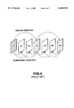
The A(n) represents an n-th coded picture, and its size represents the bit amount of the coded picture. As shown in FIG. 4, each of the pictures is encoded as an I picture, P picture, or B picture. The I picture is encoded by using its own image signal alone. The P picture is motion-compensative-predicted from an I picture or P picture immediately before and the prediction residue is coded. The B picture is motion-compensative-predicted from an I picture or P picture immediately before and immediately after, and the prediction residue is coded. The bit amount of each coded picture A(n) changes according to the picture type I, P, or B and the picture content.
Referring back to FIG. 3, the ETS(n) represents a time to encode the coded picture A(n). The interval of pictures to be encoded (i.e., ETS(n+1) -ETS(n)) is, for example, 1/29.97 seconds in the NTSC video signal, and 1/25 seconds in the PAL video signal. The DTS(n) represents a time to decode the n-th coded picture A(n). The interval of pictures to be decoded (i.e., DTS(n+1)-DTS(n)) is identical to the interval of pictures to be encoded.
In the encoder system, the region below the stepped zigzag trace in the figure represents the bit occupation amount change in the encode buffer. That is, the vertical distance from the time t on the line c-d to the stepped trace represents the bit occupation amount at time t. The vertical direction movement of the stepped trace represents an instantaneous input of a bit stream from the video encoder 12 to the encoder buffer 13, whereas the horizontal direction movement of the stepped trace indicates that no bit stream is inputted from the video encoder 12 to the encoder buffer 13 (no encoding is carried out), and the encoder buffer 13 outputs a bit stream at the bit rate R.
Description will now be directed to the change of the bit occupation amount in the encoder buffer of the encoder system.
Before time t=ETS(0), the bit occupation amount in the encoder buffer is zero. A data of the 0-th picture A(0) encoded at time t=ETS(0) is instantaneously inputted to the encoder buffer, which instantaneously increases the bit occupation amount of the encoder buffer by the bit amount of the aforementioned 0-th coded picture A(0). The encoder buffer starts output of a bit stream at t=0. The start is specified by the start controller 19 in the encoder system shown in FIG. 4. This start time do is calculated from the bit rate R and the bit occupation amount b0 at the decoding start of the decoder buffer as follows.
ETS(0)+do=0
do=(B-b0)/R
For the time duration from t=0 to the encoding time ETS(1) of the next 1-st picture A(1), a bit stream is outputted from the encoder buffer at the bit rate R, which decreases the bit occupation amount of the encoder buffer as the time lapses. At the encoding time ETS(1), the 1-st picture A(1) is encoded and supplied to the encoder buffer, which instantaneously increases the bit occupation amount of the encoder buffer by the bit amount of the 1-st picture A(1). For the time duration from t=ETS(1) to ETS(2), a bit stream is outputted from the encoder buffer at the bit rate R, which decreases the bit occupation amount of the encoder buffer as the time lapses. In the same manner, picture encoding is continued at a predetermined time interval.
The bit occupation amount in the decoder buffer is changed according to the bit occupation amount change of the aforementioned encoder buffer. In the decoder system, the region above the stepped trace represents the bit occupation amount change. That is, the vertical distance from the time t on the line c-d to the stepped trace along the vertical axis represents the bit occupation amount of the decoder buffer at time t. The vertical direction movement of the stepped trace represents that the video decoder 28 instantaneously reads out a bit stream from the decoder buffer 27, whereas the horizontal direction movement of the stepped trace represents that the video decoder 28 reads out no bit stream from the decoder buffer 27 (no decoding is carried out) and a bit stream is inputted to this decoder buffer 27 at the bit rate R.
Description will now be directed to the change of the bit occupation amount of the decoder buffer in the decoder system.
At time t=D0, input of a bit stream to the decoder buffer at the bit rate R is started. When the time duration di, i.e.,
di=b0/R
has elapsed, at time DTS (0), the 0-th picture A(0) is decoded
This moment of time di or time DTS(0) is specified by the bit stream received. The bit occupation amount of the decoder buffer is instantaneously decreased by decoding the 0-th coded picture A(0) at time DTS by the bit amount of the aforementioned 0-th coded picture A(0). Subsequently, during a following time duration up to the time DTS(1), a bit stream is inputted to the decoder buffer at the bit rate R, which increases the bit occupation amount of the decoder buffer as the time lapses. At time DTS(1), the 1-st coded picture A(1) is decoded, which instantaneously decreases the bit occupation amount of the decoder buffer by the bit amount of the 1-st coded picture A(1). In the same manner, picture decoding is continued at a predetermined time interval.
Here, T(i) represents a time interval (hereinafter, T will be referred to as a delay time) from the time ETS(i) when the i-th coded picture A(i) is encoded to the time DES(i) when the i-th coded picture A(i) is decoded. That is,
T(i)=DTS(i)-ETS(i)
In order to carry out a stable image reproduction at the side of decoder (reception) system, the aforementioned delay time T(i) should be a constant value for encoding/decoding of all the coded pictures. That is,
T=T(0)=T(1)=. . . =T(n)
Consequently, as shown in FIG. 3, the trace of the bit occupation amount of the decoder buffer is identical to the trace of the bit occupation amount of the encoder buffer which trace is advanced by the aforementioned delay time T (rightward along the horizontal axis).
Here, if it is assumed that B is the aforementioned buffer size, Oe(n) is the bit occupation amount of the encoder buffer immediately before encoding the n-th coded picture A(n), Ve(n) is the vacancy amount of the encoder buffer immediately before encoding the n-th coded picture A(n), Od(n) is the bit occupation amount of the decoder buffer immediately before decoding the n-th coded picture A(n), and Vd(n) is the vacancy amount of the decoder buffer immediately before decoding the n-th coded picture A(n), then the following relationships are satisfied.
Ve(n)=B-Oe(n)
Vd(n)=B-Od(n)
Oe(n)=Vd(n)
Ve(n)=Od(n)
B=Oe(n)+Ve(n) =Od(n)+Vd(n)=Oe(n)+Od(n)
That is, as shown in FIG. 5, control is carried out so that the sum of the bit occupation amount of the encoder buffer in the encoder system and the bit occupation amount of the VBV buffer (decoder buffer) of the decoder system be a constant value (corresponding to the buffer size B) via the aforementioned delay time T.
The delay time T is calculated by the following equation.
T=τe(n)+τd(n)+D0
 =Oe(n)/R+Od(n)/R+D0
 =B/R+D0
wherein D0 represents a transmission line delay amount (constant).
If "t" is assumed to be a period of time required for making the bit occupation amount of the encoder buffer from the aforementioned buffer size B to 0 at the output bit rate R or a period of time required for making the bit occupation amount of the decoder buffer from 0 to B at the input bit rate R, then the following relationships are satisfied.
τ=B/R=τe(n)+τd(n)                              (constant)
T=τ+d0                                                 (constant)
Assuming this buffer model, the encoder system should carry out encoding and transmission, while taking consideration not to overflow or underflow the decoder buffer of the decoder system. The decoder system can carry out a stable picture decoding while the stepped trace of the decoder system is found between the line c-d and the line e-f without exceeding the buffer size B. If the stepped trace is found above the line c-d, it means that the decoder buffer is underflown, and if the stepped trace is below the line e-f, then it means that the decoder buffer is overflown.
The encoder system encodes an n-th picture A(k), assuming the bit occupation amount of the decoder buffer when the picture A(k) is decoded. Here, the k-th picture A(k) can generate a bit amount which satisfies the following condition.
[Equation 1]
R and B are constant when t>D0
If k=0,
Od(0)=b0                                                   (1)
If k≧1, ##EQU1##
Od(k)+R×(DTS(k+1)-DTS(k))-B≦A(k)≦Od(k) (3)
wherein A(k)≧0
In the encoder system of FIG. 1, the bit amount of the picture A(i) when i<k corresponds to the bit amount S21 generated from the aforementioned video encoder 12. The rate controller 15, assuming the bit amount S22 to be assigned for the k-th picture A(k), specifies a value of the bit amount (size of the picture A(k)) which satisfies the aforementioned equation (3). The encoder system carries out such a control so as not to overflow or underflow the decoder buffer of the decoder system.
In the conventional technique as has thus far been described, there is no problem as long as the data transmission rate between the encoder system and the decoder system is a constant rate. However, if the data transmission is carried out at a variable bit rate, there arises a problem that the decoder system cannot obtain a stable picture reproduction. This problem will be detailed below with reference to FIG. 6.
Here, in the same way as the aforementioned conventional technique, the size of the encoder buffer of the encoder system is a constant and identical to the size B of the VBV buffer (decoder buffer) of the decoder system.
For transmission at a variable bit rate, for example, if the coding bit rate is changed from R1 to R2 when encoding the n-th picture A(n) and after, then, in synchronization with this, the encoder system changes the output bit rate R from the encoder buffer from R1 to R2. This change of the output bit rate R from the encoder buffer is shown in FIG. 6 as a change of the slope of line e-f to line f-g at time t=ETS(n). That is, the aforementioned output bit rate R and the coding bit rates R1 and R2 are in the relationships as follows.
R=R1:0≦t<ETS(n)
R=R2: ETS(n)≧t
wherein R1>R2
In this case, the encoder system, according to the aforementioned equations (1), (2), and (3), assumes that the possible trace of bit occupation amount of the VBV buffer of the decoder system is found between the broken line e-f-p-q and the broken line h-i-r, and the encoder system is assumed to have carried out an encoding so that the trace of the bit occupation amount of the encoder buffer is found between the broken line e-f-g and the broken line a-b-d.
In this case, as is clear from FIG. 6, there arises an underflow of the decoder buffer when decoding the n-th picture A(n).
This is because, in the case of FIG. 6, the time interval between the moment of encoding of a picture and the moment of decoding to the picture is changed when the output bit rate R is changed from the coding bit rate R1 to the bit rate R2. That is, if T1 is assumed to be the time interval while R=R1, and T2 is assumed to be the time interval while R=R2, then
B=Oe(1)+Od(1) Oe(n)+Od(n)(Oe(n)=0 in FIG. 9)
When R=R1: T1=Oe(1)/R1+Od(1)/R1+D0+B/R1+D0.
When R=R2: T2=Oe(n)/R2+Od(n)/R2+D0+B/R2+D0.
Note that D0 is a transmission line delay time (constant) and R1>R2. Consequently, T1<T2.
As can be understood from FIG. 6, in the decoder system, for the pictures A(0) to the (n-1)-th picture A(n-1), the time interval T1 between encoding a picture and decoding of the picture is unchanged, and a stable decoding can be carried out.
A problem arises when decoding the picture A(n). That is, when decoding the picture A(n), the picture A(n) has not yet completely arrived at the decoder buffer at time t=(ETS(n)+T1), and an underflow is caused. At time t=(ETS(n)+T1) in FIG. 6, the trace X shows that the decoder buffer is underflown when decoding the picture A(n). The moment of time when the picture A(n) can be correctly decoded is time t=DTS(n)=ETS(n)+T2. Thus, during the time interval F from t=(ETS(n)+T1) to t=DTS(n), decoding cannot be carried out normally and accordingly, there arises a problem in image display. That is, for example, during this time interval, the picture A(n-1) which has bee decoded immediately before continues to be displayed, i.e., the display is frozen (still).
SUMMARY OF THE INVENTION
It is therefore an object of the present invention to provide a coded signal transmission method and apparatus in which a digital signal is coded at a variable rate in an encoder system (transmission side) and is transmitted to a decoder system (reception side) at a variable bit rate while controlling so as not to overflow or underflow a decoder buffer of the decoder system.
In order to achieve the above object, when coding at a variable bit rate and transmitting at real time to a reception side (decoder system), it is necessary that a time interval from a moment of encoding of a picture to a moment of decoding of the picture be a constant value for all of the pictures involved.
In the coded signal transmission method according to the present invention, for coding a digital signal at a variable bit for transmission, a size of a transmission buffer is controlled according to a coding bit rate for temporarily storing a coded signal in the encoder system for transmission at a variable rate.
Accordingly, there is provided a code buffer which is included in the transmission buffer of the encoder system and which can be used for rate control by the encoder system is changed in size according to the coding bit rate.
More specifically, the coded buffer size which can currently be used by the encoder system is determined by the reception buffer size of the decoder system, the maximum value of the coding bit rate, and the current coding bit rate.
If it is assumed that Bmax is the reception buffer size of the decoder system, Rmax is the maximum value of the coding bit rate, and RT is the current coding bit rate, the code buffer size B of the transmission buffer is determined as follows.
B=Bmax×RT/Rmax
Here, the switching time of code buffer size of the transmission buffer is assumed to be (β-τ) wherein β is a time when the coding bit rate changes and τ is a value obtained as follows:
T=Bmax/Rmax
It should be noted that in case when the decoder system of the reception side is based on the ISO/IEC 11172-2 or ISO/IEC 13818-2 (MPEG1 or MPEG2), the encoder system assumes the reception buffer of the decoder system to be a VBV (Video Buffering Verifier) buffer defined in the ISO/IEC 11172-2 Annex C or ISO-IEC 13818-2 Annex C. In this case, a code buffer size which can be used for rate control when encoding a picture is equal to the VBV buffer size required for decoding the picture, and an output bit rate of a coded picture from the encoder buffer is equal to the input bit rate of the picture to the VBV buffer.
The VBV buffer size of the decoder system and the input bit rate to the VBV buffer which are calculated in this manner are used for controlling a bit amount to be assigned for coding an input picture and a bit amount generated, thus enabling a stable image reproduction in the decoder system (reception side) without causing an overflow or an underflow.
BRIEF DESCRIPTION OF THE DRAWING
FIG. 1 is a block diagram showing a conventional encoder system for a constant output bit rate.
FIG. 2 is a block diagram showing a conventional decoder system.
FIG. 3 shows bit occupation amount changes in the encoder system and the decoder system under a constant output bit rate.
FIG. 4 shows picture types.
FIG. 5 shows the relationship between the bit occupation amount of the buffer of the encoder system and the bit occupation amount of the buffer of the decoder system.
FIG. 6 shows a problem which occurs when the output bit rate is variable in the encoder system of FIG. 1.
FIG. 7 is block diagram of an encoder system according to an embodiment of the present invention.
FIG. 8 shows the bit occupation amount change in a buffer of the encoder system and the bit occupation amount change in a buffer of the decoder system according to the embodiment.
FIG. 9 shows the bit occupation amount change in a buffer of the encoder system and the bit occupation amount change in a buffer of the decoder system according to the embodiment.
DETAILED DESCRIPTION OF PREFERRED EMBODIMENTS
Description will now be directed to a coded signal transmission apparatus based on a coded signal transmission method according to an embodiment of the present invention with reference to the attached drawings. It should be noted that coding and transmission of a video signal will be explained according to the embodiment below. However, the present invention is not limited to a video signal but can be applied to an audio signal and the like.
FIG. 7 is a block diagram of an encoder (hereinafter, referred to as an encoder system) according to one embodiment of the present invention.
In the encoder system of FIG. 7, an input video sequence is encoded at a variable bit rate, which is then outputted at a variable rate from an encoder buffer (transmission buffer) 53. There is a great difference between the conventional encoder system of FIG. 1 and the encoder system of FIG. 7 having the encoder buffer 53 controlled by an output bit rate controller 56 and a buffer size controller 57.
That is, in the encoder system of FIG. 1, the coding bit rate R specified from the terminal 16 serves as the output bit rate R from the encoder buffer 13. Moreover, in FIG. 1, the code buffer size which can be used by the encoder system is made always equal to the VBV buffer size of the decoder system.
On the other hand, in the encoder system according to the present invention shown in FIG. 7, the output bit rate controller (specifier) 56 controls the output bit rate R at a moment of time t and the buffer size controller (specifier) 57 controls the code buffer size B which can be used at moment of time t in the encoder system.
In the encoder system of FIG. 7, a video signal is inputted from a terminal 51 and the coding bit rate RT for a current input video can be specified from a terminal 50 at the will of a user. That is, the coding bit rate RT can be changed.
A video encoder 52 encodes a current input picture so as to satisfy an assigned bit amount S61 specified from a rate controller 55 and supplies a bit stream of the coded picture to the encoder buffer 53.
The rate controller 55 is supplied with a bit occupation amount b0 of the decoder buffer when starting decoding, bit amount S62 generated by a coded picture, an output bit rate R from the encoder buffer 53 specified from the output bit rate controller 56, and a buffer size B specified from the buffer size controller 57; and calculates an assigned bit amount S61 of a following picture to be coded, the result of which is supplied to the video encoder 52 so as not to overflow or underflow the VBV buffer (decoder buffer) of the decoder system by a method which will be detailed later.
In the same ways as the conventional technique explained with reference to FIG. 1, a start controller 66 specifies an output start of a bit stream from the encoder buffer 53.
The bit stream outputted from the encoder buffer 53 at the bit rate R is supplied to a multiplexer 54. Although not depicted, the multiplexer 54 is also supplied with a coded bit stream of an audio signal. The multiplexer 54 system codes and multiplexes a plurality of input bit streams, and outputs a multiplexed transmission stream from a terminal 58.
The rate controller 55 controls the coding bit rate in the video encoder 52; the output bit rate controller 56 controls the read-out rate from the encoder buffer 53; and the buffer size controller 57 controls the rate controller 55 so as to limit the size of the encoder buffer 53. These controllers 55, 56, and 57 will be detailed below.
FIG. 8 is a first example of a diagram showing the bit occupation change of the buffer in the encoder system and that of the decoder system according to the present embodiment. FIG. 9 is a second example of such a diagram according to the present invention. Note that, in these cases, the decoder system is assumed to be identical as the conventional one explained with reference to FIG. 2.
In FIG. 2 and FIG. 3, the left side of the broken line e-f-g-h represents the bit occupation amount change in the encoder buffer 53 of the encoder system and the right side of this broken line represents the bit occupation amount change of the decoder buffer 27 of the decoder system.
The slope of the broken line e-f-g-h at a particular time t represents the bit rate R of the output from the encoder buffer 53 at time t and, if viewed from the decoder system, represents the bit rate R of the input to the decoder buffer 27 at time t.
The vertical distance between the broken line e-f-g-h and the broken line a-b-c-d represents the code buffer size B which can be used for the rate control by the encoder system at time t. The vertical distance between the broken line e-f-g-h and the broken line i-j-k-l represents the VBV buffer size B required at time t for the decoder system. The buffer size B which can be used at time t=ETS(i) by the encoder system is identical to the buffer size B required at t=DTS(i) for the decoder system.
The symbols D0, A(n), ETS(n), DTS(n), and T(n) have the same meaning as in the aforementioned FIG. 3. That is, D0 represents a constant transmission line delay time which exists between the encoder system and the decoder system. The A(n) represents the n-th coded picture and its size represents the bit amount of this n-th coded picture A(n). The ETS(n) represents the time to encode the n-th coded picture A(n). The DTS(n) represents the time to decode this n-th coded picture A(n). The T(n) represents the time interval between the time ETS(n) when the n-th coded picture A(n) is encoded and the time DTS(n) when this n-th coded picture A(n) is decoded.
Here, a case is considered when for an input video sequence, the coding bit rate RT is specified as follows.
RT=RX: a coding bit rate from the 0-th coded picture A(0) to the (n-1)-th coded picture A(n-1), wherein ETS(0)≦t<ETS(n).
RT=RY: a coding bit rate from the n-th coded picture A(n) to the (m-1)-th coded picture A(m-1), wherein ETS(n)≦t<ETS(m).
RT=RZ: a coding bit rate from the m-t h coded picture A(m) and after, wherein ETS(m)≦t.
The aforementioned coding bit rate RX, RY, and RZ are specified from the terminal 50 according to the input video signal from the terminal 51. In this example, the coding bit rate RX is the maximum bit rate and the following relation is assumed:
RX>RZ>RY
Here, T(i) represents the time interval from the time ETS(i) when the i-th coded picture A(i) is encoded to the time DTS(i) when this i-th coded picture A(i) is decoded, i.e., T(i)=DTS(i) ETS(i).
In order to obtain a stable image reproduction in the decoder system, the aforementioned time interval T(i) should be constant for the i-th coded picture, i.e., the following equation (1-1) should be satisfied for all the coded pictures.
T=T(0)=T(1)=. . . =T(n)                                    Equation (1-1)
Consequently, as shown in FIG. 8 and FIG. 9, the trace of the bit occupation amount of the decoder buffer should be identical to the trace of the bit occupation amount of the encoder buffer which has been advanced by time T (moved rightward along the horizontal axis in the figures). Hereinafter, explanation will be given how to determine the buffer size B and the output bit rate R in order to satisfy Equation (1-1).
In this example, the output bit rate R from the encoder buffer 53 is changed as follows:
R=RX: 0≦t<α1
F=RY: α1≦t<α2
R=RZ: α2≦t
The procedure to determine the time al and the time α2 will be explained later.
The buffer size controller 57 determines a code buffer size B which can be used at time t by the encoder system according to the VBV buffer size of the decoder system, the maximum value of the coding bit; rate, and the coding bit rate RT at time t.
The buffer size B at time t=0, α1, and α2 will be explained. Here, it is assumed that:
B=BX: code buffer size of the encoder system at time t=0
B=BY: code buffer size of the encoder system at time t=α1
B=BZ: code buffer size of the encoder system at time t=α2
R=RX: output bit rate from the encoder buffer at time t=0
R=RY: output bit rate from the encoder buffer at time t=α1
R=RY: output bit rate from the encoder buffer at time t=α2
The BY and BZ can be calculated according to the encoder buffer size BX at the maximum bit rate RX. For example, the BX is assumed to be identical to the VBV buffer size of the decoder system and
BX=1.75M bits
At the respective output bit rates (RX, RY, RZ), a period of time τ required to make zero the bit occupation amount of the respective encoder buffers from the aforementioned BX, BY, and BZ. That is, the bit occupation amounts BY and BZ are determined as follows:
τ=BX/RX=BY/RY=BZ/RZ                                    Equation (1-2)
That is,
BY=BX×RY/RX
BZ=BX×RZ/RX
Here, RX>RZ>RY. Therefore,
BX>BZ>BY
If the Equation (1-2) is satisfied for the buffer size B and the output bit rate R, then
T=T(i)=τ+D0                                            (Constant)
τ=Rmax/Bmax
wherein
Bmax is the VBV buffer size of the decoder system, for example, 1.75M bits;
Rmax is the maximum value of the coding bit rate, i.e., RX in this example; and
D0 is the transmission line delay amount (constant).
Next, explanation will given on the values α1 and α2 and the buffer size B of the encoder system during the time intervals: (α1-τ)≦t<α1 and (α2-τ)≦t<α2.
Here, α1 and α2 are the moments of time when the output bit rate from the encoder buffer is changed. These moments of time α1 and α2 may be increased, allowing greater values than 0000000α1+Δτ and α2+Δτ(Δτ≧0).
The output bit rate R from the encoder buffer is changed from RX to RY at t=α1 and from RY to RZ at t=α2.
The buffer size B is gradually reduced from BX to BY during the time interval (α1-τ)≦t<α1 and gradually increased from BY to BZ during the time interval (a2-t)<t<a2. In these time intervals, the buffer size B can be determined by one of the following two methods.
The first method can be employed in a case when a predetermined value is assumed for the bit occupation amount Oe(n) of the encoder buffer immediately before encoding a picture A(n) at time ETS(n) or the bit occupation amount Od(n) of the encoder buffer immediately before decoding a picture A(n) at time DTS(n).
FIG. 8 is used to explain this first method. In this case, in order to make Oe(n) the bit occupation amount of the encoder buffer at time ETS(n) of FIG. 8, it is necessary that the rate controller 55 of FIG. 7 adjust the bit amount to be assigned for the preceding pictures.
In this case, it is possible to determine beforehand the moment of time t=a1 to change the output bit rate R from RX to RY in the encoder system as follows.
τe(n)=Oe/RX
or
τe(n)=τ-Od(n)/RY
α1=ETS(n)+τe(n)                                  Equation (1-3)
The encoder buffer size B in the interval (α1-τ)<t<α1 can be determined as follows.
x=t-(α1-τ)
B=BX×(τ-x)/τ+BY×x/τ                Equation (1-4)
Thus, in this first method, it is possible to determine beforehand the moment of time t=α1, and accordingly to determine the output bit rate R at time t and the buffer size B which can be used. The same applies to the time interval (α2-τ)≦t<α2.
The second method is employed when a predetermined value is not assumed for the bit occupation amount Oe(n) of the encoder buffer immediately before encoding a picture A(n) at time ETS(n) (or the bit occupation amount Od(n) of the decoder buffer immediately before decoding the picture A(n) at time DTS(n)).
FIG. 9 shows an example for explaining this second method. Generally, this second case is considered to be used more often.
As shown in FIG. 9, in this second method, the following is assumed:
α1=ETS(n)                                            Equation (1-5)
The encoder buffer size B during the time interval (α1-τ)≦t<α1 is determined from Equation (1-4). The output bit rate R from the encoder buffer is changed from RX to RY at time t=α1 (ETS(n)).
Thus, in this second method, it is possible to determine the output bit rate R from the encoder buffer and the buffer size B. The same applies to the time interval (αb 2-τ)≦t<a2.
When employing the method shown in FIG. 9, the rate controller 55 of FIG. 7 need not obtain the aforementioned bit occupation amount Oe(n) of the encoder buffer which is supplied to the output bit rate controller 56 and to the buffer size controller 57.
In FIG. 8 and FIG. 9, at time t, the code buffer size B which can be used in the encoder system and the output bit rate R can be described as follows.
do=(BX-b0)/RX: a delay time from ETS(0) to a start of the bit stream output from the encoder buffer.
R=RX:0≦t<α1
R=RY:α1≦t<α2
R=RZ:α2≦t
B=BX:-τ≦t<(α1-τ)
B=BY:α1≦t<(α2-τ)
B=BZ:α2≦t
The bit occupation amounts BX, BY and BZ can be calculated from the Equation (1-2). The values α1 and α2 and the code buffer size at time t in the ranges of (α1-τ)≦t <α1 and (α2-τ)≦t<α2 can be calculated by using one of the aforementioned two methods from the Equations (1-3) and (1-4) or Equations (1-5) and (1-4).
Assuming the aforementioned buffer model, the encoder system should carry out encoding while controlling not to overflow or underflow the decoder buffer. That is, the encoder system should control the rate controller 55 so that the stepped trace of the decoder system at time t will not exceed the decoder buffer size B, i.e., will be between the broken line e-f-g-h and the broken line i-j-k-l.
The encoder system encodes a k-th picture A(k), assuming a state of decoder bit occupation amount when the picture A(k) is decoded. Here, the bit amount generated by the k-th picture A(k) (i.e., size of the A(k)) should satisfy the following condition.
[Equation 2]
When k=0,
Od(0)=b0                                                   Equation (1-6)
When k≧1, ##EQU2##
Od(k)+R×(DTS(k+1)-DTS(k))-B≦A(k)≦Od(k) Equation (1-8)
wherein A(k)≧0
Here, R is the input bit rate to the decoder buffer 27 at time t, and B is the necessary size for the decoder buffer at time t.
Note that if there is no problem of underflow of the encoder buffer, the Equation (1-8) can be replaced by Equation (1-9).
A(k)≦Od(k)                                          Equation (1-9)
wherein A(k)≧0 and 0≦Od(k)<B.
When using this equation (1-9), if the output bit rate from the encoder buffer 53 of FIG. 7 is less than the specified R, the multiplexer 54 carries out bit stuffing so as to increase the output bit rate to R.
The input bit rate R to the decoder buffer at time t is identical to the output bit rate from the encoder buffer at time (t-D0). Therefore, the following are satisfied.
R=RX:D0≦t<α1+Do
R=RY:α1+D0≦t<α2+D0
R=RZ:α2+D0<t
Moreover, the size B required for the decoder buffer at time t is identical to the size used for the code buffer of the encoder system at time t-(D0+τ). Therefore, the following are satisfied.
B=BX: D0≦t<(α1+D0)
B=BY: (α1+D0+t)≦t<(α2+D0)
B=BZ: (α2+D0+t)≦t
The values α1 and α2 can be determined by any one of the aforementioned two methods, respectively from Equation (1-3) and Equation (1-5).
The size B required for the decoder buffer in the time interval (α1+D0)≦t<(α1+D0+τ) can be calculated as follows corresponding to the aforementioned two methods.
x=t-(α1+D0)
B=BX×(τ+x)/τ+BY×x/τ
The size B for the time interval (α2+D0)≦t<(α2+D0+τ) can be calculated in the similar manner.
For simplification, it is possible to assume D0=0. Then, the bit stream input to the decoder buffer can be considered, starting at t=0, and the time handling is simplified.
In the encoder system of FIG. 7, the picture A(i) when i<k corresponds to a signal S62. The rate controller 55 assumes S61 as the bit amount assigned for the k-th picture A(k) and specifies a value which satisfies the condition of Equation (1-8) (size of k-th coded picture A(k)). By this control, encoding can be carried out without causing overflow or underflow of the decoder buffer.
Description will now be directed to operation of such an encoder with reference to FIG. 7.
In FIG. 7, a terminal 50 is supplied with the aforementioned coded bit rate RT which is supplied prior to the video sequence from the terminal 51.
The start controller 66 is supplied via the terminal 65 with the bit occupation amount b0 at a decoding start of the decoder buffer, the first coding bit rate RT (=RX), and the first decoder buffer size from the rate controller 55, and using these data calculates the output start delay time do as follows.
do=(BX-b0)/RX
The start controller 66 controls to start output of a coded signal with the delay of do from the encoding start.
The output bit rate controller 56 controls the encoder buffer 53 as follows. For example, if the coding bit rate RT=RX up to the (n-1)-th picture A(n-1) is to be changed to the bit rate RT=RY for the next picture A(n) and after, the time β to change the coding bit rate is determined so that the code buffer size B of the encoder buffer 53 is switched from BX to BY at time (β-τ). According to the first method shown in FIG. 8, the rate controller 55 supplies the buffer bit occupation amount Oe(n) immediately before encoding the picture A(n) at the aforementioned time ETS(n), according to which the time β is obtained as follows.
β=ETS(n)+Oe(n)/RX
According to the second method shown in FIG. 9, the time ETS(n) for encoding the picture A(n) is obtained as the time β.
The rate controller 55 is supplied with a code amount S62 from the video encoder 52, the output bit rate R from the output bit rate controller 56, and the decoder buffer size B from the buffer size controller 57, and according to the aforementioned VBV model, calculates a bit amount S61 to be assigned for the next picture to be coded, which amount is sent to the video encoder 52, so that no overflow or underflow of the decoder buffer of size B is caused. The buffer size B for this rate control is assumed to be BX at the beginning. The decoder buffer size B is then gradually reduced from BX to BY from time (β-τ), i.e., the aforementioned time τ (=Rmax/Bmax) earlier than the coded rate switching time β, until the switching time β. At the switching time β and after, the buffer size B is assumed to be BY for controlling the bit amount S61 to be assigned for coding in the video encoder 52 without causing overflow or underflow of the decoder buffer.
The technique according to the embodiment of the present invention as has thus far been described can be summed up as follows. When encoding and transmitting a digital signal at a variable bit rate, the size of a transmission buffer (encoder buffer 53) for temporarily storing the coded signal of the encoder system is controlled according to the coding bit rate. The transmission buffer is provided with a code buffer used for rate control in the encoder system. The size of this code buffer is determined according to the reception buffer size of the decoder system, the maximum value of the coding bit rate, and the current coding bit rate.
Here, the size B of the aforementioned code buffer of the transmission buffer is determined as follows assuming Bmax as the reception buffer size of the decoder system, Rmax as the maximum value of the coding bit rate, and RT as the current coding bit rate.
B=Bmax×RT/Rmax
It is assumed that the size of the aforementioned code buffer of the transmission buffer is switched at (β-τ), i.e., earlier by τ than the moment at time β when the coding bit rate is changed, wherein
t=Bmax/Rmax
The switching moment time β of the code buffer size B of the transmission buffer can be determined by two methods. The first method determines the switching moment according to the time for encoding or decoding a picture immediately after the picture for which the coding bit rate is changed; the buffer occupation amount at that time; and the preceding coding bit rate before the bit rate change. The second method assumes the aforementioned moment of time β the encoding time of a picture immediately after the picture for which the coding bit rate has been changed.
The encoder system according to the aforementioned embodiment has a merit that the transmission delay time between the encoder system and the decoder system is small. Consequently, the encoder system according to the present embodiment is especially effective for a case which requires a least amount of delay such as a news program.
It should be noted that the present invention is not limited to the aforementioned embodiments. For example, the digital signal is not limited to a video signal but can also be applied to an audio signal. The present invention can be modified in various ways within the scope of the invention.
In the coded signal transmission method and apparatus according to the present invention, the size of the transmission buffer for temporarily storing a coded signal in the encoder system is controlled according to the coding bit rate so that a digital signal is coded at a variable bit rate and transmitted from the encoder system (transmission side) to the decoder system (reception side) at a variable bit rate without causing overflow or underflow of the reception buffer of the decoder system, thus enabling to obtain a stable signal reproduction.
Control of this size of the transmission buffer can be carried out, for example, by modifying the code buffer size which can be used for the rate control by the encoder system according to the coding bit rate. Here, it is assumed that the code buffer is included in the transmission buffer. In this case, the code buffer size which can be used currently by the encoder system is determined by the reception buffer size, the maximum value of the coding bit rate, and the current coding bit rate of the decoder system.
In this example, a stable signal reproduction can be realized in response to the variable bit rate. Moreover, in this example, there is a merit that the delay time between the encoder system and the decoder system is small, which is especially effective when the least amount of delay is required such as in a news program.

Claims (27)

What is claimed is:
1. A coded signal transmission method for coding and transmitting a digital signal at a variable bit rate, comprising the step of:
controlling a size of a transmission buffer for temporarily storing a coded signal according to a coding bit rate;
determining an assigned bit amount of a subsequent picture to be coded in accordance with a bit amount of a coded picture generated from an encoder; and
determining an output bit rate based on said coding bit rate;
wherein said step of controlling said size of said transmission buffer includes the step of varying the transmission buffer size based on the output bit rate and the assigned bit amount.
2. The method of claim 1 wherein said transmission buffer has a code buffer to be used for rate control, the size of the code buffer being determined according to a reception buffer size of a decoder, a maximum value of a coding bit rate, and a current coding bit rate.
3. The method of claim 1 wherein a code buffer size B of the transmission buffer is determined by an equation below:
B=Bmax×RT/Rmax
wherein Bmax is a reception buffer size of a decoder, Rmax is the maximum value of a coding bit rate, and RT is a current coding bit rate.
4. The method of claim 3 wherein said code buffer size of the transmission buffer is switched at a moment of time earlier by τ than a moment of time when the coding bit rate is changed.
5. The method of claim 4 wherein said switching moment of time α of the code buffer size of the transmission buffer is determined according to a time period to encode or decode a picture immediately after a picture when the coding bit rate is changed, a current buffer occupation amount at that time, and a preceding coding bit rate prior to the bit rate change.
6. The method of claim 4 wherein τ equals Bmax/Rmax.
7. The method of claim 2 wherein a code buffer size B of the transmission buffer is determined by an equation below:
B=Bmax×RT/Rmax
wherein Bmax is a reception buffer size of a decoder, Rmax is the maximum value of a coding bit rate, and RT is a current coding bit rate.
8. The method of claim 7 wherein said code buffer size of the transmission buffer is switched at a moment of time earlier by τ than a moment of time when the coding bit rate is changed.
9. The method of claim 8 wherein said switching moment of time α of the code buffer size of the transmission buffer is determined according to a time period to encode or decode a picture immediately after a picture when the coding bit rate is changed, a current buffer occupation amount at that time, and a preceding coding bit rate prior to the bit rate change.
10. The method of claim 9 wherein τ equals Bmax/Rmax.
11. The method of claim 8 wherein τ equals Bmax/Rmax.
12. The method of claim 5 wherein τ equals Bmax/Rmax.
13. A coded signal transmission apparatus for coding and transmitting a digital signal at a variable bit rate, comprising:
a transmission buffer;
a first controller for controlling a size of a code buffer for temporarily storing a coded signal in said transmission buffer so as to control a transmission bit rate according to a reception buffer size of a decoder, a maximum value of a coding bit rate, and a current coding bit rate, the first controller configured to generate an output bit rate based on said coding bit rate; and
a second controller for inputting a bit occupation amount of the code buffer and receiving a bit amount of a coded picture generated from an encoder to calculate an assigned bit amount of a subsequent picture to be coded;
wherein said transmission buffer size is configured to vary in accordance with the output bit rate and the assigned bit amount.
14. The apparatus of claim 13 wherein said transmission buffer has a code buffer to be used for rate control, the size of the code buffer being determined according to a reception buffer size of a decoder, a maximum value of a coding bit rate, and a current coding bit rate.
15. The apparatus of claim 13 wherein said code buffer size B of the transmission buffer is determined by an equation below:
B=Bmax×RT/Rmax
wherein Bmax is a reception buffer size of a decoder, Rmax is the maximum value of a coding bit rate, and RT is a current coding bit rate.
16. The apparatus of claim 15 wherein said code buffer size of the transmission buffer is switched at a moment of time earlier by τ than a moment of time when the coding bit rate is changed.
17. The apparatus of claim 16 wherein said switching moment of time α of the code buffer size of the transmission buffer is determined according to a time period to encode or decode a picture immediately after a picture when the coding bit rate is changed, a current buffer occupation amount at that time, and a preceding coding bit rate prior to the bit rate change.
18. The apparatus of claim 16 wherein τ equals Bmax/Rmax.
19. The apparatus of claim 14 wherein said code buffer size B of the transmission buffer is determined by an equation below:
B=Bmax×RT/Rmax
wherein Bmax is a reception buffer size of a decoder, Rmax is the maximum value of a coding bit rate, and RT is a current coding bit rate.
20. The apparatus of claim 19 wherein said code buffer size of the transmission buffer is switched at a moment of time earlier by τ than a moment of time when the coding bit rate is changed.
21. The apparatus of claim 20 wherein said switching moment of time α of the code buffer size of the transmission buffer is determined according to a time period to encode or decode a picture immediately after a picture when the coding bit rate is changed, a current buffer occupation amount at that time, and a preceding coding bit rate prior to the bit rate change.
22. The apparatus of claim 21 wherein τ equals Bmax/Rmax.
23. The apparatus of claim 20 wherein τ equals Bmax/Rmax.
24. The apparatus of claim 13 wherein said code buffer size of the transmission buffer is switched at a moment of time earlier by τ than a moment of time when the coding bit rate is changed.
25. The apparatus of claim 24 wherein said switching moment of time α of the code buffer size of the transmission buffer is determined according to a time period to encode or decode a picture immediately after a picture when the coding bit rate is changed, a current buffer occupation amount at that time, and a preceding coding bit rate prior to the bit rate change.
26. The apparatus of claim 25 wherein τ equals Bmax/Rmax.
27. The apparatus of claim 24 wherein τ equals Bmax/Rmax.
US08/958,589 1996-11-07 1997-10-29 Coded signal transmission method and apparatus Expired - Lifetime US6160915A (en)

Applications Claiming Priority (2)

Application Number Priority Date Filing Date Title
JP8-295477 1996-11-07
JP29547796 1996-11-07

Publications (1)

Publication Number Publication Date
US6160915A true US6160915A (en) 2000-12-12

Family

ID=17821117

Family Applications (2)

Application Number Title Priority Date Filing Date
US08/958,569 Expired - Fee Related US6188700B1 (en) 1996-11-07 1997-10-28 Method and apparatus for encoding MPEG signals using variable rate encoding and dynamically varying transmission buffers
US08/958,589 Expired - Lifetime US6160915A (en) 1996-11-07 1997-10-29 Coded signal transmission method and apparatus

Family Applications Before (1)

Application Number Title Priority Date Filing Date
US08/958,569 Expired - Fee Related US6188700B1 (en) 1996-11-07 1997-10-28 Method and apparatus for encoding MPEG signals using variable rate encoding and dynamically varying transmission buffers

Country Status (1)

Country Link
US (2) US6188700B1 (en)

Cited By (12)

* Cited by examiner, † Cited by third party
Publication number Priority date Publication date Assignee Title
US6351564B1 (en) * 1998-02-03 2002-02-26 U.S. Philips Corporation Method of switching of coded video sequences and corresponding device
US6414725B1 (en) * 1998-04-16 2002-07-02 Leitch Technology Corporation Method and apparatus for synchronized multiple format data storage
FR2823056A1 (en) * 2001-04-03 2002-10-04 Sagem Digital word transmission distant station/base station having digital words distant station recorded and transmission channel pass band rate found/digital words changed/transmitted following pass band rate.
US6688714B1 (en) * 1998-07-10 2004-02-10 Koninklijke Philips Electronics N.V. Bit-rate modification
EP1783945A2 (en) * 2000-10-13 2007-05-09 Sony Corporation Data communication quality control system, transmission system and receiver
US20070115815A1 (en) * 2003-06-11 2007-05-24 Nec Corporation Receiver, transmitter and transmission/reception system for media signal
CN100353352C (en) * 2003-04-15 2007-12-05 华为技术有限公司 Method of reducing data transmission delay in coding decoding process and its device
US7768934B2 (en) 2004-10-29 2010-08-03 Sharp Kabushiki Kaisha Communications device, communications method, communications program, storage medium storing the communications program, and communications system
US20110200118A1 (en) * 2002-11-29 2011-08-18 Sony Corporation Encoding apparatus and the method
US20120166670A1 (en) * 2010-12-28 2012-06-28 Yoshinobu Kure Transmitting apparatus, transmitting method, and program
US9712437B2 (en) 2013-11-29 2017-07-18 Bridgeworks Limited Transmitting data
US10283091B2 (en) * 2014-10-13 2019-05-07 Microsoft Technology Licensing, Llc Buffer optimization

Families Citing this family (46)

* Cited by examiner, † Cited by third party
Publication number Priority date Publication date Assignee Title
WO1998032252A1 (en) * 1997-01-21 1998-07-23 Sony Corporation Coded signal transmission method and device
JP4232209B2 (en) * 1998-01-19 2009-03-04 ソニー株式会社 Compressed image data editing apparatus and compressed image data editing method
JPH11298890A (en) * 1998-04-13 1999-10-29 Hitachi Ltd Method and system for compression or expansion of image data, image transmission system and monitor system using the same
US6490250B1 (en) * 1999-03-09 2002-12-03 Conexant Systems, Inc. Elementary stream multiplexer
US6813663B1 (en) 1999-11-02 2004-11-02 Apple Computer, Inc. Method and apparatus for supporting and presenting multiple serial bus nodes using distinct configuration ROM images
US6457086B1 (en) 1999-11-16 2002-09-24 Apple Computers, Inc. Method and apparatus for accelerating detection of serial bus device speed signals
US7266617B1 (en) * 2000-01-18 2007-09-04 Apple Inc. Method and apparatus for border node behavior on a full-duplex bus
US6639918B1 (en) 2000-01-18 2003-10-28 Apple Computer, Inc. Method and apparatus for border node behavior on a full-duplex bus
US6757273B1 (en) * 2000-02-07 2004-06-29 Nokia Corporation Apparatus, and associated method, for communicating streaming video in a radio communication system
US7050453B1 (en) 2000-02-17 2006-05-23 Apple Computer, Inc. Method and apparatus for ensuring compatibility on a high performance serial bus
US7050460B1 (en) * 2000-04-14 2006-05-23 Ati International Srl Method and apparatus for multiplexing data streams using time constraints
US6618785B1 (en) 2000-04-21 2003-09-09 Apple Computer, Inc. Method and apparatus for automatic detection and healing of signal pair crossover on a high performance serial bus
CN1322759C (en) * 2000-04-27 2007-06-20 三菱电机株式会社 Coding apparatus and coding method
JPWO2002032083A1 (en) * 2000-10-13 2004-02-26 ソニー株式会社 Data communication quality control system, transmission system and receiver
US8127326B2 (en) * 2000-11-14 2012-02-28 Claussen Paul J Proximity detection using wireless connectivity in a communications system
WO2002047388A2 (en) * 2000-11-14 2002-06-13 Scientific-Atlanta, Inc. Networked subscriber television distribution
JP2002165148A (en) * 2000-11-29 2002-06-07 Sony Corp Data processing apparatus and method, and record medium
US20030192047A1 (en) * 2002-03-22 2003-10-09 Gaul Michael A. Exporting data from a digital home communication terminal to a client device
WO2003094536A2 (en) * 2002-05-02 2003-11-13 Ciena Corporation Distribution stage for enabling efficient expansion of a switching network
US20050201485A1 (en) * 2002-05-22 2005-09-15 Koninkljke Phillips Electronics N.V. Transmission method using a virtual reception buffer to absorb fluctuation of the channel transmission rate
US7516470B2 (en) 2002-08-02 2009-04-07 Cisco Technology, Inc. Locally-updated interactive program guide
US7908625B2 (en) * 2002-10-02 2011-03-15 Robertson Neil C Networked multimedia system
US20040068754A1 (en) * 2002-10-02 2004-04-08 Russ Samuel H. Expandable tuning capability
US20040068752A1 (en) * 2002-10-02 2004-04-08 Parker Leslie T. Systems and methods for providing television signals to multiple televisions located at a customer premises
JP3534742B1 (en) 2002-10-03 2004-06-07 株式会社エヌ・ティ・ティ・ドコモ Moving picture decoding method, moving picture decoding apparatus, and moving picture decoding program
US8046806B2 (en) * 2002-10-04 2011-10-25 Wall William E Multiroom point of deployment module
US20040068739A1 (en) * 2002-10-04 2004-04-08 Russ Samuel H. Networked multimedia system having a multi-room interactive network guide
US20040133911A1 (en) * 2002-10-04 2004-07-08 Russ Samuel H. Subscriber network in a satellite system
US7360235B2 (en) * 2002-10-04 2008-04-15 Scientific-Atlanta, Inc. Systems and methods for operating a peripheral record/playback device in a networked multimedia system
US8094640B2 (en) * 2003-01-15 2012-01-10 Robertson Neil C Full duplex wideband communications system for a local coaxial network
EP1595405B1 (en) * 2003-02-18 2019-12-04 Nokia Technologies Oy Method and device for transmitting media data in nal units over rtp
CN101668215A (en) * 2003-02-18 2010-03-10 诺基亚有限公司 Picture decoding method
US7353284B2 (en) * 2003-06-13 2008-04-01 Apple Inc. Synchronized transmission of audio and video data from a computer to a client via an interface
US20050201471A1 (en) * 2004-02-13 2005-09-15 Nokia Corporation Picture decoding method
US7296205B2 (en) * 2004-02-18 2007-11-13 Nokia Corporation Data repair
US9124907B2 (en) * 2004-10-04 2015-09-01 Nokia Technologies Oy Picture buffering method
US20060117354A1 (en) * 2004-11-29 2006-06-01 Mark Schutte Consolidating video-on-demand (VOD) services with multi-room personal video recording (MR-PVR) services
US20060225105A1 (en) * 2005-04-05 2006-10-05 Scientific-Atlanta, Inc. Networked multi-room system ad insertion
US20070036177A1 (en) * 2005-08-12 2007-02-15 Sarnoff Corporation Method and apparatus for managing delivery of video over a digital subscriber line
US7876998B2 (en) 2005-10-05 2011-01-25 Wall William E DVD playback over multi-room by copying to HDD
US8477789B2 (en) * 2005-12-28 2013-07-02 Panasonic Corporation Transmission device and reception device
KR101442273B1 (en) * 2007-05-17 2014-09-23 소니 주식회사 Information processing device and method
JP2009111932A (en) * 2007-10-31 2009-05-21 Panasonic Corp Moving image decoding device
KR101431272B1 (en) * 2008-01-30 2014-08-20 엘지전자 주식회사 Apparatus and method for adjusting bit rate in security device connected external storage
US20100017530A1 (en) * 2008-06-23 2010-01-21 Hitachi, Ltd. Priority-Based Physical Layer Transmission Rate Control For Video Streaming Over Wireless Networks
US20100226444A1 (en) * 2009-03-09 2010-09-09 Telephoto Technologies Inc. System and method for facilitating video quality of live broadcast information over a shared packet based network

Citations (6)

* Cited by examiner, † Cited by third party
Publication number Priority date Publication date Assignee Title
US5510906A (en) * 1992-08-31 1996-04-23 Sony Corporation Motion picture recording method, motion picture recording medium, and motion picture reproducing apparatus
US5686963A (en) * 1995-12-26 1997-11-11 C-Cube Microsystems Method for performing rate control in a video encoder which provides a bit budget for each frame while employing virtual buffers and virtual buffer verifiers
US5771357A (en) * 1995-08-23 1998-06-23 Sony Corporation Encoding/decoding fields of predetermined field polarity apparatus and method
US5771316A (en) * 1995-12-26 1998-06-23 C-Cube Microsystems Fade detection
US5774206A (en) * 1995-05-10 1998-06-30 Cagent Technologies, Inc. Process for controlling an MPEG decoder
US5864368A (en) * 1995-02-28 1999-01-26 Sony Corporation Picture signal editing and encoding method and apparatus, signal recording medium and picture signal decoding method and apparatus

Family Cites Families (5)

* Cited by examiner, † Cited by third party
Publication number Priority date Publication date Assignee Title
US5543853A (en) * 1995-01-19 1996-08-06 At&T Corp. Encoder/decoder buffer control for variable bit-rate channel
US5619341A (en) * 1995-02-23 1997-04-08 Motorola, Inc. Method and apparatus for preventing overflow and underflow of an encoder buffer in a video compression system
US5677969A (en) * 1995-02-23 1997-10-14 Motorola, Inc. Method, rate controller, and system for preventing overflow and underflow of a decoder buffer in a video compression system
JPH098814A (en) * 1995-06-21 1997-01-10 Fuji Xerox Co Ltd Data transmission device and method thereof and data communication system
US5793436A (en) * 1996-06-17 1998-08-11 Samsung Electronics Co., Ltd. Buffer occupancy control method for use in video buffering verifier

Patent Citations (6)

* Cited by examiner, † Cited by third party
Publication number Priority date Publication date Assignee Title
US5510906A (en) * 1992-08-31 1996-04-23 Sony Corporation Motion picture recording method, motion picture recording medium, and motion picture reproducing apparatus
US5864368A (en) * 1995-02-28 1999-01-26 Sony Corporation Picture signal editing and encoding method and apparatus, signal recording medium and picture signal decoding method and apparatus
US5774206A (en) * 1995-05-10 1998-06-30 Cagent Technologies, Inc. Process for controlling an MPEG decoder
US5771357A (en) * 1995-08-23 1998-06-23 Sony Corporation Encoding/decoding fields of predetermined field polarity apparatus and method
US5686963A (en) * 1995-12-26 1997-11-11 C-Cube Microsystems Method for performing rate control in a video encoder which provides a bit budget for each frame while employing virtual buffers and virtual buffer verifiers
US5771316A (en) * 1995-12-26 1998-06-23 C-Cube Microsystems Fade detection

Non-Patent Citations (6)

* Cited by examiner, † Cited by third party
Title
International Standard, ISO/IEC 11172 2, First Edition, Aug. 1, 1993, Annex C, Information Technology Coding of Moving Pictures and Associated Audio for Digital Storage Media at up to About 1,5 MBIT/S Part 2: Video . *
International Standard, ISO/IEC 11172-2, First Edition, Aug. 1, 1993, Annex C, "Information Technology--Coding of Moving Pictures and Associated Audio for Digital Storage Media at up to About 1,5 MBIT/S--Part 2: Video".
International Standard, ISO/IEC 13818 2, First Edition, May 15, 1996, Annex C, Information Technology Generic Coding of Moving Pictures and Associated Audio Information: Video . *
International Standard, ISO/IEC 13818-2, First Edition, May 15, 1996, Annex C, "Information Technology--Generic Coding of Moving Pictures and Associated Audio Information: Video".
U.S. application No. 08/167,415, filed Dec. 14, 1993. *
U.S. application No. 08/958,569, filed Oct. 28, 1997. *

Cited By (21)

* Cited by examiner, † Cited by third party
Publication number Priority date Publication date Assignee Title
US6351564B1 (en) * 1998-02-03 2002-02-26 U.S. Philips Corporation Method of switching of coded video sequences and corresponding device
US6414725B1 (en) * 1998-04-16 2002-07-02 Leitch Technology Corporation Method and apparatus for synchronized multiple format data storage
US6688714B1 (en) * 1998-07-10 2004-02-10 Koninklijke Philips Electronics N.V. Bit-rate modification
EP1783945A2 (en) * 2000-10-13 2007-05-09 Sony Corporation Data communication quality control system, transmission system and receiver
FR2823056A1 (en) * 2001-04-03 2002-10-04 Sagem Digital word transmission distant station/base station having digital words distant station recorded and transmission channel pass band rate found/digital words changed/transmitted following pass band rate.
EP1248419A1 (en) * 2001-04-03 2002-10-09 Sagem S.A. Method and apparatus for transmitting digital data
US20110200096A1 (en) * 2002-11-29 2011-08-18 Sony Corporation Encoding apparatus and the method
US9654812B2 (en) * 2002-11-29 2017-05-16 Sony Corporation Encoding apparatus and the method
US20110200118A1 (en) * 2002-11-29 2011-08-18 Sony Corporation Encoding apparatus and the method
US20110200117A1 (en) * 2002-11-29 2011-08-18 Sony Corporation Encoding apparatus and the method
US20110280320A1 (en) * 2002-11-29 2011-11-17 Sony Corporation Encoding apparatus and the method
US9516361B2 (en) * 2002-11-29 2016-12-06 Sony Corporation Encoding apparatus and the method
CN100353352C (en) * 2003-04-15 2007-12-05 华为技术有限公司 Method of reducing data transmission delay in coding decoding process and its device
US20070115815A1 (en) * 2003-06-11 2007-05-24 Nec Corporation Receiver, transmitter and transmission/reception system for media signal
US7768934B2 (en) 2004-10-29 2010-08-03 Sharp Kabushiki Kaisha Communications device, communications method, communications program, storage medium storing the communications program, and communications system
US20120166670A1 (en) * 2010-12-28 2012-06-28 Yoshinobu Kure Transmitting apparatus, transmitting method, and program
US9712437B2 (en) 2013-11-29 2017-07-18 Bridgeworks Limited Transmitting data
US9729437B2 (en) 2013-11-29 2017-08-08 Bridgeworks Limited Transferring data between a first network node and a second network node by measuring a capability of different communication paths
US9954776B2 (en) 2013-11-29 2018-04-24 Bridgeworks Limited Transferring data between network nodes
US10084699B2 (en) 2013-11-29 2018-09-25 Bridgeworks Limited Transferring data
US10283091B2 (en) * 2014-10-13 2019-05-07 Microsoft Technology Licensing, Llc Buffer optimization

Also Published As

Publication number Publication date
US6188700B1 (en) 2001-02-13

Similar Documents

Publication Publication Date Title
US6160915A (en) Coded signal transmission method and apparatus
US5619341A (en) Method and apparatus for preventing overflow and underflow of an encoder buffer in a video compression system
US6459811B1 (en) Bursty data transmission of compressed video data
US5602592A (en) Moving picture compressed signal changeover apparatus
CA2185704C (en) Method, rate controller, and system for preventing overflow and underflow of a decoder buffer
US6208759B1 (en) Switching between bit-rate reduced signals
US6097435A (en) Video system with selectable bit rate reduction
US7379497B2 (en) Encoded data outputting apparatus and method
WO1999005870A2 (en) Method of switching between video sequences and corresponding device
JP2000511740A (en) How to seamlessly join a video encoder
JPH0795090A (en) Transcoding device
US6504576B2 (en) Digital signal coding method and apparatus, signal recording medium, and signal transmission method for recording a moving picture signal and an acoustic signal
EP1410642A2 (en) Video transmission system video transmission unit and methods of encoding decoding video data
AU2002321220A1 (en) Video transmission system video transmission unit and methods of encoding decoding video data
US6504850B1 (en) Encoded signal transmission method and encoded signal transmission apparatus
Haskell et al. Multiplexing of variable rate encoded streams
US6147627A (en) Coder for segmented coding of an input signal using controllable quantization based on quantization step size and buffer fullness
JPH10190745A (en) Encoding signal transmitting method/device
US6885703B1 (en) Video code processing method, which can generate continuous moving pictures
JPH10190746A (en) Encoding signal transmitting method/device
JP4216553B2 (en) Digital broadcast signal switching device and digital broadcast signal switching method
Hoang et al. Multiplexing VBR video sequences onto a CBR channel with lexicographic optimization
AU678926C (en) Method and apparatus for preventing overflow and underflow of an encoder buffer in a video compression system
JP2001339718A (en) Method for outputting encode and multiplexing control apparatus
KR20000068612A (en) Method of switching between video sequences and corresponding device

Legal Events

Date Code Title Description
AS Assignment

Owner name: SONY CORPORATION, JAPAN

Free format text: ASSIGNMENT OF ASSIGNORS INTEREST;ASSIGNORS:KATO, MOTOKI;KOYANAGI, HIDEKI;REEL/FRAME:009095/0191

Effective date: 19980120

STCF Information on status: patent grant

Free format text: PATENTED CASE

FPAY Fee payment

Year of fee payment: 4

FPAY Fee payment

Year of fee payment: 8

FEPP Fee payment procedure

Free format text: PAYER NUMBER DE-ASSIGNED (ORIGINAL EVENT CODE: RMPN); ENTITY STATUS OF PATENT OWNER: LARGE ENTITY

Free format text: PAYOR NUMBER ASSIGNED (ORIGINAL EVENT CODE: ASPN); ENTITY STATUS OF PATENT OWNER: LARGE ENTITY

FPAY Fee payment

Year of fee payment: 12