US6164716A - Energy dissipating body panel assembly - Google Patents
Energy dissipating body panel assembly Download PDFInfo
- Publication number
- US6164716A US6164716A US09/215,693 US21569398A US6164716A US 6164716 A US6164716 A US 6164716A US 21569398 A US21569398 A US 21569398A US 6164716 A US6164716 A US 6164716A
- Authority
- US
- United States
- Prior art keywords
- body panel
- intermediate member
- panel assembly
- structural material
- sides
- Prior art date
- Legal status (The legal status is an assumption and is not a legal conclusion. Google has not performed a legal analysis and makes no representation as to the accuracy of the status listed.)
- Expired - Lifetime
Links
Images


Classifications
-
- B—PERFORMING OPERATIONS; TRANSPORTING
- B60—VEHICLES IN GENERAL
- B60J—WINDOWS, WINDSCREENS, NON-FIXED ROOFS, DOORS, OR SIMILAR DEVICES FOR VEHICLES; REMOVABLE EXTERNAL PROTECTIVE COVERINGS SPECIALLY ADAPTED FOR VEHICLES
- B60J5/00—Doors
- B60J5/04—Doors arranged at the vehicle sides
- B60J5/042—Reinforcement elements
- B60J5/0452—Reinforcement elements including foams or expanded materials
-
- B—PERFORMING OPERATIONS; TRANSPORTING
- B60—VEHICLES IN GENERAL
- B60J—WINDOWS, WINDSCREENS, NON-FIXED ROOFS, DOORS, OR SIMILAR DEVICES FOR VEHICLES; REMOVABLE EXTERNAL PROTECTIVE COVERINGS SPECIALLY ADAPTED FOR VEHICLES
- B60J5/00—Doors
- B60J5/04—Doors arranged at the vehicle sides
- B60J5/042—Reinforcement elements
- B60J5/045—Panel type elements
Definitions
- the present invention relates generally to a body panel assembly for absorbing energy and, more particularly, to a vehicle door for dissipating impact energy exerted on a vehicle panel.
- Vehicles have been designed to withstand energy on impact and to ensure the safety of passengers.
- vehicle doors have been constructed with padding along their inside panel.
- the padding is positioned only in select areas and only absorbs a limited amount of energy.
- the limited amount of padding has not increased passenger safety.
- these doors with interior padding have diminished the amount of interior space available in the vehicle.
- a vehicle door designed to absorb impact energy during side impact. Further it is desirable to reduce the cost and the weight of the vehicle door. This is accomplished by removing impact beams positioned between the panels of the door. Further, it is desirable to save time and money during assembly by attaching the door hardware to an intermediate panel.
- the present invention overcomes the short comings of the prior art.
- the present invention provides a body panel assembly for dissipating impact energy.
- the body panel assembly includes an inner member having a desired inner area.
- the inner area is defined by a perimeter which includes a top, bottom, and sides.
- the assembly has an outer member with a desired outer area, defined by a perimeter which includes a top, bottom, and sides.
- the inner and outer members are positioned with respect to one another to define a cavity.
- An intermediate member is positioned in the cavity between the inner and outer members.
- the intermediate member extends from the top to the bottom of the inner and outer members.
- a structural material is positioned in a space between the outer member and the intermediate member for dissipating impact energy.
- the structural material extends from the top to the bottom of the intermediate and outer members and is comprised of foam or a honeycomb plastic.
- FIG. 1 illustrates a vehicle with the body panel assembly of the present invention.
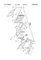
- FIG. 2 is an exploded perspective view of the body panel assembly according to the present invention.
- FIG. 2a is an exploded perspective view of a second embodiment of the present invention.
- FIG. 3 is a perspective view partially in section view of the connection of the body panel assembly.
- FIG. 4 is a cross-section view of the body panel assembly with the structural material comprised of a honeycomb plastic.
- FIG. 5 is a cross-section view of the body panel assembly with the structural material comprised of foam.
- FIG. 6 is a cross-section view of the connection of the bottom of the members of the body panel assembly where the intermediate member is welded to the inner member and the outer member is hem-flanged to the inner member.
- FIG. 7 is a cross-section view of the connection of the bottom of the members of the body panel assembly where the intermediate member is fastened by a fastener, or welded, to the inner member and the outer member is hem-flanged to the intermediate member.
- FIG. 8 is a cross-section view of the bottom of the members where a live hinge secures the inner panel to the intermediate panel.
- a vehicle 11 is illustrated with a front quarter 14, a rear quarter 16, and a tailgate 18.
- the front quarter 14 and the rear quarter 16 are separated by doors 19 for access to the interior of the vehicle 11.
- the doors 19 and the tailgate 18 are comprised of the body panel assembly 20 of the present invention.
- FIG. 2 illustrates the body panel assembly 20 as applied to a vehicle door 19.
- the body panel assembly 20 includes an inner member 22, an outer member 24, and an intermediate member 26 positioned in the cavity 28 between the inner member 22 and the outer member 24.
- the inner member 22 includes various cutouts to receive and secure the door hardware.
- the hardware includes the window mechanism as well as speakers and the like.
- the inner member 22 has an inner area defined by a perimeter including a top 32, bottom 34, and sides 36.
- the outer member 24 likewise has an outer area defined by a perimeter including a top 38, a bottom 40, and sides 42.
- the inner member 22 and the outer member 24 are positioned with respect to each other such that the tops 32 and 38, bottoms 34 and 40, and sides 36 and 42 of the inner member 22 and the outer member 24 are aligned with respect to one another.
- the body panel assembly 20 further includes end pieces 44.
- the end pieces 44 are defined by a perimeter including a top 46, bottom 48, and sides 50.
- the sides 50 of the end pieces 44 are coupled to the sides 36 and 42 of the inner member 22 and the outer member 24 defining the width of the cavity 28.
- the intermediate member 26 has an intermediate area defined by a perimeter which includes a top 52, bottom 54, and sides 56.
- the intermediate member extends in the cavity from the top 28 and 34 to the bottom 30 and 36 of the inner member 22 and the outer member 24.
- FIG. 3 is a cross sectional view of the body panel assembly 20.
- the cross section illustrates the inner member 22, the intermediate member 26, and the outer member 24 aligned with respect to one another.
- the members are spaced to allow a structural material 58, such as foam or, as shown, a honey comb plastic, to be positioned in the space between the outer member 24 and the intermediate member 26.
- the structural material 58 fills the entire space between the intermediate member 26 and the outer member 24 as shown in FIGS. 4 and 5.
- the structural material 58 extends top to bottom and side to side with respect to the outer member 24 and the intermediate member 26.
- the body panel assembly 20 is designed so the structural material 58 absorbs the impact energy during side impact. Since the structural material 58 dissipates the impact energy, impact beams are not required to absorb additional energy. Further, the body panel assembly 20 is lighter and more cost efficient with out the use of the impact beams inside the body panels.
- the door hardware 60 may be attached to the intermediate member 26 during the assembly process and occupy the space between the intermediate member 26 and the inner member 22 of the body panel assembly 20.
- the door hardware 60 does not extend through the intermediate member 26 and is accessed from only one side. This assembly process enables the door to be constructed efficiently with out any dislocation of the wiring or hardware.
- FIG. 5 illustrates the body panel assembly 20 with the structural material 58 as foam 62.
- FIG. 4 illustrates the body panel assembly 20 with the structural material 46 as a honeycomb plastic 64.
- the intermediate member 26 may include at least one horizontal rib 66 attached at both sides 56 of the intermediate member 26.
- the horizontal rib 66 is positioned on the intermediate member 26 to provide an area to secure the door hardware 60 to the intermediate member 26.
- FIGS. 6, 7 and 8 illustrate alternative connections for the inner member 22, the intermediate member 26 and the outer member 24 of the body panel assembly 20.
- FIG. 7 illustrates the inner member 22 welded or screwed to the intermediate member 26.
- the intermediate member 26 is hem-flanged to the outer member 24.
- FIG. 6 illustrates the intermediate member 26 welded to the inner member 22.
- the outer member 24 is then hem-flanged around the inner member 22.
- FIG. 8 shows the inner member 22 attached to the intermediate member by pop rivets or the like.
- the inner member creates a live hinge enabling the inner member to be pulled away from the remainder of the door assembly.
Abstract
Description
Claims (18)
Priority Applications (1)
| Application Number | Priority Date | Filing Date | Title |
|---|---|---|---|
| US09/215,693 US6164716A (en) | 1998-12-18 | 1998-12-18 | Energy dissipating body panel assembly |
Applications Claiming Priority (1)
| Application Number | Priority Date | Filing Date | Title |
|---|---|---|---|
| US09/215,693 US6164716A (en) | 1998-12-18 | 1998-12-18 | Energy dissipating body panel assembly |
Publications (1)
| Publication Number | Publication Date |
|---|---|
| US6164716A true US6164716A (en) | 2000-12-26 |
Family
ID=22803987
Family Applications (1)
| Application Number | Title | Priority Date | Filing Date |
|---|---|---|---|
| US09/215,693 Expired - Lifetime US6164716A (en) | 1998-12-18 | 1998-12-18 | Energy dissipating body panel assembly |
Country Status (1)
| Country | Link |
|---|---|
| US (1) | US6164716A (en) |
Cited By (28)
| Publication number | Priority date | Publication date | Assignee | Title |
|---|---|---|---|---|
| US20020162208A1 (en) * | 2000-12-14 | 2002-11-07 | Georg Wurm | Method of assembling a door |
| FR2828862A1 (en) | 2001-08-24 | 2003-02-28 | Renault | Automobile side panel assembly comprises foam kinetic energy absorption device forming interior trimming panel with outer face fixed on intermediate panel |
| US6536832B1 (en) * | 1999-09-28 | 2003-03-25 | Arvin Meritor Gmbh | Vehicle door including structural element support for a functional component |
| US6554348B1 (en) * | 2002-06-04 | 2003-04-29 | Dan H. Gernstein | Bus body |
| US6672642B1 (en) * | 2002-06-11 | 2004-01-06 | Alcoa Inc. | Hybrid tailgate |
| US6896320B2 (en) * | 2002-01-22 | 2005-05-24 | Dow Global Technologies Inc. | Reinforced structural body |
| US20050248180A1 (en) * | 2004-05-06 | 2005-11-10 | Grupo Antolin-Ingenieria, S.A. | Energy absorbing element and manufacturing procedure thereof |
| US20060028048A1 (en) * | 2004-08-05 | 2006-02-09 | Ryan Brenneman | Composite cargo door/ramp |
| US7041355B2 (en) | 2001-11-29 | 2006-05-09 | Dow Global Technologies Inc. | Structural reinforcement parts for automotive assembly |
| US7084210B2 (en) | 2002-12-27 | 2006-08-01 | Dow Global Technologies Inc. | Heat activated epoxy adhesive and use in a structural foam insert |
| US7097794B2 (en) | 2002-04-15 | 2006-08-29 | Dow Global Technologies, Inc. | Vehicular structural members and method of making the members |
| US20070120394A1 (en) * | 2005-11-28 | 2007-05-31 | Mitsubishi Jidosha Kogyo Kabushiki Kaisha | Door construction |
| US7250124B2 (en) | 2003-03-05 | 2007-07-31 | Dow Global Technologies Inc. | Structural reinforcement article and process for preparation thereof |
| US20070262107A1 (en) * | 2004-08-05 | 2007-11-15 | Ryan Brenneman | Cargo carrier having a door with a lift-assisting hinge apparatus |
| US20090165392A1 (en) * | 2007-12-27 | 2009-07-02 | Toyoda Gosei Co., Ltd. | Vehicle door |
| DE102008006850A1 (en) * | 2008-01-31 | 2009-08-06 | Bayerische Motoren Werke Aktiengesellschaft | Reinforced wall component, in particular for a motor vehicle |
| US20090224571A1 (en) * | 2008-03-06 | 2009-09-10 | Benjamin Huttsell | Dual Support Pad for a Vehicle Door |
| US20110036047A1 (en) * | 2008-08-13 | 2011-02-17 | Caterpillar Japan Ltd. | Door panel |
| US20110169302A1 (en) * | 2010-01-09 | 2011-07-14 | Ford Global Technologies, Llc | Door block arrangement for energy absorbing vehicle door |
| US20140125087A1 (en) * | 2011-04-28 | 2014-05-08 | Magna Closures Inc. | Door assembly with carrier with intrusion member |
| FR3000702A1 (en) * | 2013-01-07 | 2014-07-11 | Automobiles Ligier | Panel for use in body i.e. door, of car, has reinforcement core comprising internal and external surfaces, where internal surface is covered by covering skin and located on outside part of panel and external surface forms face of panel |
| US20150008697A1 (en) * | 2013-07-03 | 2015-01-08 | Honda Motor Co., Ltd. | Vehicle door |
| US20150097390A1 (en) * | 2011-05-14 | 2015-04-09 | Daimer Ag | Arrangment of a Side Door On a Body Of a Motor Vehicle |
| CN104553693A (en) * | 2015-01-04 | 2015-04-29 | 陈焕祥 | Door device for automobile |
| US9308577B2 (en) | 2011-09-30 | 2016-04-12 | ArcelorMittal Investigacion y Desarrolli, S.L. | Lightweight steel door for vehicle and method for manufacturing the same |
| CN110154703A (en) * | 2019-06-28 | 2019-08-23 | 东莞职业技术学院 | Composite filled Aluminum Honeycomb Cores and the arrangements for automotive doors for using the aluminium core |
| US10882383B2 (en) | 2018-11-30 | 2021-01-05 | Nissan North America, Inc. | Vehicle energy absorbing member |
| US11529851B2 (en) * | 2016-09-09 | 2022-12-20 | Teijin Automotive Technologies, Inc. | Composite vehicle door components formed by sheet molding compound-resin transfer molding assemblies |
Citations (18)
| Publication number | Priority date | Publication date | Assignee | Title |
|---|---|---|---|---|
| US3791693A (en) * | 1971-06-04 | 1974-02-12 | Ford Motor Co | Vehicle door, in particular for motor vehicles |
| US3829149A (en) * | 1973-02-09 | 1974-08-13 | L & L Prod Inc | Beam construction |
| US3868796A (en) * | 1973-04-04 | 1975-03-04 | Ford Motor Co | Side door intrusion protection |
| US3964208A (en) * | 1974-06-01 | 1976-06-22 | Daimler-Benz Aktiengesellschaft | Door for vehicle, especially passenger motor vehicle |
| US4786100A (en) * | 1986-05-07 | 1988-11-22 | Bayerische Motoren Werke Aktiengesellschaft | Vehicle side door |
| US4861097A (en) * | 1987-09-18 | 1989-08-29 | Essex Composite Systems | Lightweight composite automotive door beam and method of manufacturing same |
| US4901500A (en) * | 1987-09-18 | 1990-02-20 | Essex Composite Systems | Lightweight composite beam |
| US5040335A (en) * | 1991-03-18 | 1991-08-20 | Davidson Textron Inc. | Inner panel assembly with integral energy absorber |
| US5306066A (en) * | 1992-10-15 | 1994-04-26 | Ford Motor Company | Energy absorbing vehicle doors |
| US5306068A (en) * | 1991-08-30 | 1994-04-26 | Toray Industries Inc. | Automobile door |
| US5395135A (en) * | 1992-11-02 | 1995-03-07 | Ford Motor Company | Energy absorbing vehicle door and side panels |
| US5466031A (en) * | 1993-06-24 | 1995-11-14 | Nissan Motor Co., Ltd. | Door structure for vehicle |
| US5536060A (en) * | 1995-02-17 | 1996-07-16 | General Motors Corporation | Reinforced vehicle door |
| US5577794A (en) * | 1994-12-12 | 1996-11-26 | General Motors Corporation | Push-out target vehicle side door |
| US5580119A (en) * | 1994-02-25 | 1996-12-03 | Nissan Motor Co., Ltd. | Door for automotive vehicles |
| US5595415A (en) * | 1994-06-08 | 1997-01-21 | Plasto Sa | Twin-wall composite lining for automobiles |
| US5749600A (en) * | 1994-08-31 | 1998-05-12 | Toyota Jidosha Kabushiki Kaisha | Door trim energy absorbing structure |
| US5924760A (en) * | 1996-11-29 | 1999-07-20 | General Motors Corporation | One-piece corrugated anti-intrusion barrier and method |
-
1998
- 1998-12-18 US US09/215,693 patent/US6164716A/en not_active Expired - Lifetime
Patent Citations (20)
| Publication number | Priority date | Publication date | Assignee | Title |
|---|---|---|---|---|
| US3791693A (en) * | 1971-06-04 | 1974-02-12 | Ford Motor Co | Vehicle door, in particular for motor vehicles |
| US3829149A (en) * | 1973-02-09 | 1974-08-13 | L & L Prod Inc | Beam construction |
| US3868796A (en) * | 1973-04-04 | 1975-03-04 | Ford Motor Co | Side door intrusion protection |
| US3964208A (en) * | 1974-06-01 | 1976-06-22 | Daimler-Benz Aktiengesellschaft | Door for vehicle, especially passenger motor vehicle |
| US4786100A (en) * | 1986-05-07 | 1988-11-22 | Bayerische Motoren Werke Aktiengesellschaft | Vehicle side door |
| US4861097A (en) * | 1987-09-18 | 1989-08-29 | Essex Composite Systems | Lightweight composite automotive door beam and method of manufacturing same |
| US4901500A (en) * | 1987-09-18 | 1990-02-20 | Essex Composite Systems | Lightweight composite beam |
| US5040335A (en) * | 1991-03-18 | 1991-08-20 | Davidson Textron Inc. | Inner panel assembly with integral energy absorber |
| US5435619A (en) * | 1991-08-30 | 1995-07-25 | Toray Industries, Inc. | Automobile door |
| US5306068A (en) * | 1991-08-30 | 1994-04-26 | Toray Industries Inc. | Automobile door |
| US5306066A (en) * | 1992-10-15 | 1994-04-26 | Ford Motor Company | Energy absorbing vehicle doors |
| US5395135A (en) * | 1992-11-02 | 1995-03-07 | Ford Motor Company | Energy absorbing vehicle door and side panels |
| US5466031A (en) * | 1993-06-24 | 1995-11-14 | Nissan Motor Co., Ltd. | Door structure for vehicle |
| US5707098A (en) * | 1993-06-24 | 1998-01-13 | Nissan Motor Co., Ltd. | Door structure for vehicle |
| US5580119A (en) * | 1994-02-25 | 1996-12-03 | Nissan Motor Co., Ltd. | Door for automotive vehicles |
| US5595415A (en) * | 1994-06-08 | 1997-01-21 | Plasto Sa | Twin-wall composite lining for automobiles |
| US5749600A (en) * | 1994-08-31 | 1998-05-12 | Toyota Jidosha Kabushiki Kaisha | Door trim energy absorbing structure |
| US5577794A (en) * | 1994-12-12 | 1996-11-26 | General Motors Corporation | Push-out target vehicle side door |
| US5536060A (en) * | 1995-02-17 | 1996-07-16 | General Motors Corporation | Reinforced vehicle door |
| US5924760A (en) * | 1996-11-29 | 1999-07-20 | General Motors Corporation | One-piece corrugated anti-intrusion barrier and method |
Cited By (44)
| Publication number | Priority date | Publication date | Assignee | Title |
|---|---|---|---|---|
| US6536832B1 (en) * | 1999-09-28 | 2003-03-25 | Arvin Meritor Gmbh | Vehicle door including structural element support for a functional component |
| US20020162208A1 (en) * | 2000-12-14 | 2002-11-07 | Georg Wurm | Method of assembling a door |
| US7231717B2 (en) * | 2000-12-14 | 2007-06-19 | Meritor Light Vehicle Systems - France | Method of assembling a door |
| FR2828862A1 (en) | 2001-08-24 | 2003-02-28 | Renault | Automobile side panel assembly comprises foam kinetic energy absorption device forming interior trimming panel with outer face fixed on intermediate panel |
| US7041355B2 (en) | 2001-11-29 | 2006-05-09 | Dow Global Technologies Inc. | Structural reinforcement parts for automotive assembly |
| US6896320B2 (en) * | 2002-01-22 | 2005-05-24 | Dow Global Technologies Inc. | Reinforced structural body |
| US7838100B2 (en) | 2002-04-15 | 2010-11-23 | Dow Global Technologies Inc. | Vehicular structural members and method of making the members |
| US7097794B2 (en) | 2002-04-15 | 2006-08-29 | Dow Global Technologies, Inc. | Vehicular structural members and method of making the members |
| US6554348B1 (en) * | 2002-06-04 | 2003-04-29 | Dan H. Gernstein | Bus body |
| US6672642B1 (en) * | 2002-06-11 | 2004-01-06 | Alcoa Inc. | Hybrid tailgate |
| US7084210B2 (en) | 2002-12-27 | 2006-08-01 | Dow Global Technologies Inc. | Heat activated epoxy adhesive and use in a structural foam insert |
| US7250124B2 (en) | 2003-03-05 | 2007-07-31 | Dow Global Technologies Inc. | Structural reinforcement article and process for preparation thereof |
| US20050248180A1 (en) * | 2004-05-06 | 2005-11-10 | Grupo Antolin-Ingenieria, S.A. | Energy absorbing element and manufacturing procedure thereof |
| US20060028048A1 (en) * | 2004-08-05 | 2006-02-09 | Ryan Brenneman | Composite cargo door/ramp |
| US7213860B2 (en) * | 2004-08-05 | 2007-05-08 | Nappanee Window, Llc | Composite cargo door/ramp |
| US20070182202A1 (en) * | 2004-08-05 | 2007-08-09 | Ryan Brenneman | Composite cargo door/ramp |
| US20070262107A1 (en) * | 2004-08-05 | 2007-11-15 | Ryan Brenneman | Cargo carrier having a door with a lift-assisting hinge apparatus |
| US20070120394A1 (en) * | 2005-11-28 | 2007-05-31 | Mitsubishi Jidosha Kogyo Kabushiki Kaisha | Door construction |
| US8510997B2 (en) * | 2005-11-28 | 2013-08-20 | Mitsubishi Jidosha Kogyo K.K. | Door construction |
| US20090165392A1 (en) * | 2007-12-27 | 2009-07-02 | Toyoda Gosei Co., Ltd. | Vehicle door |
| CN101468590B (en) * | 2007-12-27 | 2012-11-28 | 丰田合成株式会社 | Vehicle door |
| US8091286B2 (en) * | 2007-12-27 | 2012-01-10 | Toyoda Gosei Co., Ltd. | Vehicle door |
| DE102008006850A1 (en) * | 2008-01-31 | 2009-08-06 | Bayerische Motoren Werke Aktiengesellschaft | Reinforced wall component, in particular for a motor vehicle |
| US20090224571A1 (en) * | 2008-03-06 | 2009-09-10 | Benjamin Huttsell | Dual Support Pad for a Vehicle Door |
| US7857375B2 (en) | 2008-03-06 | 2010-12-28 | Honda Motor Co., Ltd. | Dual support pad for a vehicle door |
| CN101959720B (en) * | 2008-03-06 | 2014-07-09 | 本田技研工业株式会社 | Dual support pad for a vehicle door |
| US20110036047A1 (en) * | 2008-08-13 | 2011-02-17 | Caterpillar Japan Ltd. | Door panel |
| US8186131B2 (en) * | 2008-08-13 | 2012-05-29 | Caterpillar Japan, Ltd. | Door panel |
| US7992920B2 (en) * | 2010-01-09 | 2011-08-09 | Ford Global Technologies, Llc | Door block arrangement for energy absorbing vehicle door |
| US20110169302A1 (en) * | 2010-01-09 | 2011-07-14 | Ford Global Technologies, Llc | Door block arrangement for energy absorbing vehicle door |
| US9126470B2 (en) * | 2011-04-28 | 2015-09-08 | Magna Closures Inc. | Door assembly with carrier with intrusion member |
| US20140125087A1 (en) * | 2011-04-28 | 2014-05-08 | Magna Closures Inc. | Door assembly with carrier with intrusion member |
| CN108909415A (en) * | 2011-04-28 | 2018-11-30 | 马格纳·克劳祖雷斯有限公司 | Door component with load-bearing part and with anti-intrusion part |
| US20150097390A1 (en) * | 2011-05-14 | 2015-04-09 | Daimer Ag | Arrangment of a Side Door On a Body Of a Motor Vehicle |
| US9254732B2 (en) * | 2011-05-14 | 2016-02-09 | Daimler Ag | Arrangment of a side door on a body of a motor vehicle |
| US9308577B2 (en) | 2011-09-30 | 2016-04-12 | ArcelorMittal Investigacion y Desarrolli, S.L. | Lightweight steel door for vehicle and method for manufacturing the same |
| FR3000702A1 (en) * | 2013-01-07 | 2014-07-11 | Automobiles Ligier | Panel for use in body i.e. door, of car, has reinforcement core comprising internal and external surfaces, where internal surface is covered by covering skin and located on outside part of panel and external surface forms face of panel |
| US9180815B2 (en) * | 2013-07-03 | 2015-11-10 | Honda Motor Co., Ltd. | Vehicle door |
| CN104276011A (en) * | 2013-07-03 | 2015-01-14 | 本田技研工业株式会社 | Vehicle door |
| US20150008697A1 (en) * | 2013-07-03 | 2015-01-08 | Honda Motor Co., Ltd. | Vehicle door |
| CN104553693A (en) * | 2015-01-04 | 2015-04-29 | 陈焕祥 | Door device for automobile |
| US11529851B2 (en) * | 2016-09-09 | 2022-12-20 | Teijin Automotive Technologies, Inc. | Composite vehicle door components formed by sheet molding compound-resin transfer molding assemblies |
| US10882383B2 (en) | 2018-11-30 | 2021-01-05 | Nissan North America, Inc. | Vehicle energy absorbing member |
| CN110154703A (en) * | 2019-06-28 | 2019-08-23 | 东莞职业技术学院 | Composite filled Aluminum Honeycomb Cores and the arrangements for automotive doors for using the aluminium core |
Similar Documents
| Publication | Publication Date | Title |
|---|---|---|
| US6164716A (en) | Energy dissipating body panel assembly | |
| US6299239B1 (en) | Vehicle body structure | |
| US8002338B2 (en) | Front vehicle body structure | |
| US5531499A (en) | Collapsible automotive trim panel boss | |
| US4307911A (en) | Reinforcement means for resisting side impacts against an automobile door | |
| US5560672A (en) | Energy absorbing beam | |
| US7992920B2 (en) | Door block arrangement for energy absorbing vehicle door | |
| KR950009031Y1 (en) | Front body structure of an automotive vehicle | |
| EP1657141B1 (en) | Automobile rear body structure | |
| JPH0769147A (en) | Bumper stay structure | |
| JPH05286364A (en) | Door structure for vehicle | |
| JPH07164878A (en) | Side shock absorbing structure in vehicle | |
| JP3622266B2 (en) | Rear structure of the car body | |
| JP2852204B2 (en) | Car front body structure | |
| JP3001173B2 (en) | Car | |
| JP3518202B2 (en) | Automotive door panel structure | |
| KR100361539B1 (en) | Reinforcement structure of rear package tray of vehicle | |
| JPH05162594A (en) | Bumper structure of automobile | |
| JP4408472B2 (en) | Body structure of one box car | |
| KR200145032Y1 (en) | Door striker with shock absorber | |
| KR200147676Y1 (en) | Door striker for a car | |
| KR20030038841A (en) | Back panel structure for van type vehicle | |
| JPH09207568A (en) | Car body structure | |
| JP2001315664A (en) | Lower body structure for vehicle | |
| JPH07132777A (en) | Car body reinforcing structure |
Legal Events
| Date | Code | Title | Description |
|---|---|---|---|
| AS | Assignment |
Owner name: DAIMLER CHRYSLER CORPORATION, MICHIGAN Free format text: ASSIGNMENT OF ASSIGNORS INTEREST;ASSIGNORS:PALAZZOLO, JOSEPH A.;HUI, ANNA;REEL/FRAME:009780/0030 Effective date: 19981218 |
|
| STCF | Information on status: patent grant |
Free format text: PATENTED CASE |
|
| FPAY | Fee payment |
Year of fee payment: 4 |
|
| AS | Assignment |
Owner name: WILMINGTON TRUST COMPANY, DELAWARE Free format text: GRANT OF SECURITY INTEREST IN PATENT RIGHTS - FIRST PRIORITY;ASSIGNOR:CHRYSLER LLC;REEL/FRAME:019773/0001 Effective date: 20070803 Owner name: WILMINGTON TRUST COMPANY,DELAWARE Free format text: GRANT OF SECURITY INTEREST IN PATENT RIGHTS - FIRST PRIORITY;ASSIGNOR:CHRYSLER LLC;REEL/FRAME:019773/0001 Effective date: 20070803 |
|
| AS | Assignment |
Owner name: WILMINGTON TRUST COMPANY, DELAWARE Free format text: GRANT OF SECURITY INTEREST IN PATENT RIGHTS - SECOND PRIORITY;ASSIGNOR:CHRYSLER LLC;REEL/FRAME:019767/0810 Effective date: 20070803 Owner name: WILMINGTON TRUST COMPANY,DELAWARE Free format text: GRANT OF SECURITY INTEREST IN PATENT RIGHTS - SECOND PRIORITY;ASSIGNOR:CHRYSLER LLC;REEL/FRAME:019767/0810 Effective date: 20070803 |
|
| FPAY | Fee payment |
Year of fee payment: 8 |
|
| AS | Assignment |
Owner name: DAIMLERCHRYSLER COMPANY LLC, MICHIGAN Free format text: CHANGE OF NAME;ASSIGNOR:DAIMLERCHRYSLER CORPORATION;REEL/FRAME:021779/0793 Effective date: 20070329 |
|
| AS | Assignment |
Owner name: CHRYSLER LLC, MICHIGAN Free format text: CHANGE OF NAME;ASSIGNOR:DAIMLERCHRYSLER COMPANY LLC;REEL/FRAME:021826/0001 Effective date: 20070727 |
|
| AS | Assignment |
Owner name: US DEPARTMENT OF THE TREASURY, DISTRICT OF COLUMBI Free format text: GRANT OF SECURITY INTEREST IN PATENT RIGHTS - THIR;ASSIGNOR:CHRYSLER LLC;REEL/FRAME:022259/0188 Effective date: 20090102 Owner name: US DEPARTMENT OF THE TREASURY,DISTRICT OF COLUMBIA Free format text: GRANT OF SECURITY INTEREST IN PATENT RIGHTS - THIR;ASSIGNOR:CHRYSLER LLC;REEL/FRAME:022259/0188 Effective date: 20090102 |
|
| AS | Assignment |
Owner name: CHRYSLER LLC, MICHIGAN Free format text: RELEASE BY SECURED PARTY;ASSIGNOR:US DEPARTMENT OF THE TREASURY;REEL/FRAME:022910/0273 Effective date: 20090608 |
|
| AS | Assignment |
Owner name: CHRYSLER LLC, MICHIGAN Free format text: RELEASE OF SECURITY INTEREST IN PATENT RIGHTS - FIRST PRIORITY;ASSIGNOR:WILMINGTON TRUST COMPANY;REEL/FRAME:022910/0498 Effective date: 20090604 Owner name: CHRYSLER LLC, MICHIGAN Free format text: RELEASE OF SECURITY INTEREST IN PATENT RIGHTS - SECOND PRIORITY;ASSIGNOR:WILMINGTON TRUST COMPANY;REEL/FRAME:022910/0740 Effective date: 20090604 Owner name: NEW CARCO ACQUISITION LLC, MICHIGAN Free format text: ASSIGNMENT OF ASSIGNORS INTEREST;ASSIGNOR:CHRYSLER LLC;REEL/FRAME:022915/0001 Effective date: 20090610 Owner name: THE UNITED STATES DEPARTMENT OF THE TREASURY, DIST Free format text: SECURITY AGREEMENT;ASSIGNOR:NEW CARCO ACQUISITION LLC;REEL/FRAME:022915/0489 Effective date: 20090610 Owner name: CHRYSLER LLC,MICHIGAN Free format text: RELEASE OF SECURITY INTEREST IN PATENT RIGHTS - FIRST PRIORITY;ASSIGNOR:WILMINGTON TRUST COMPANY;REEL/FRAME:022910/0498 Effective date: 20090604 Owner name: CHRYSLER LLC,MICHIGAN Free format text: RELEASE OF SECURITY INTEREST IN PATENT RIGHTS - SECOND PRIORITY;ASSIGNOR:WILMINGTON TRUST COMPANY;REEL/FRAME:022910/0740 Effective date: 20090604 Owner name: NEW CARCO ACQUISITION LLC,MICHIGAN Free format text: ASSIGNMENT OF ASSIGNORS INTEREST;ASSIGNOR:CHRYSLER LLC;REEL/FRAME:022915/0001 Effective date: 20090610 Owner name: THE UNITED STATES DEPARTMENT OF THE TREASURY,DISTR Free format text: SECURITY AGREEMENT;ASSIGNOR:NEW CARCO ACQUISITION LLC;REEL/FRAME:022915/0489 Effective date: 20090610 |
|
| AS | Assignment |
Owner name: CHRYSLER GROUP LLC, MICHIGAN Free format text: CHANGE OF NAME;ASSIGNOR:NEW CARCO ACQUISITION LLC;REEL/FRAME:022919/0126 Effective date: 20090610 Owner name: CHRYSLER GROUP LLC,MICHIGAN Free format text: CHANGE OF NAME;ASSIGNOR:NEW CARCO ACQUISITION LLC;REEL/FRAME:022919/0126 Effective date: 20090610 |
|
| AS | Assignment |
Owner name: CHRYSLER GROUP LLC, MICHIGAN Free format text: RELEASE BY SECURED PARTY;ASSIGNOR:THE UNITED STATES DEPARTMENT OF THE TREASURY;REEL/FRAME:026343/0298 Effective date: 20110524 Owner name: CHRYSLER GROUP GLOBAL ELECTRIC MOTORCARS LLC, NORT Free format text: RELEASE BY SECURED PARTY;ASSIGNOR:THE UNITED STATES DEPARTMENT OF THE TREASURY;REEL/FRAME:026343/0298 Effective date: 20110524 |
|
| AS | Assignment |
Owner name: CITIBANK, N.A., NEW YORK Free format text: SECURITY AGREEMENT;ASSIGNOR:CHRYSLER GROUP LLC;REEL/FRAME:026404/0123 Effective date: 20110524 |
|
| AS | Assignment |
Owner name: CITIBANK, N.A., NEW YORK Free format text: SECURITY AGREEMENT;ASSIGNOR:CHRYSLER GROUP LLC;REEL/FRAME:026435/0652 Effective date: 20110524 |
|
| FPAY | Fee payment |
Year of fee payment: 12 |
|
| AS | Assignment |
Owner name: JPMORGAN CHASE BANK, N.A., ILLINOIS Free format text: SECURITY AGREEMENT;ASSIGNOR:CHRYSLER GROUP LLC;REEL/FRAME:032384/0640 Effective date: 20140207 |
|
| AS | Assignment |
Owner name: FCA US LLC, MICHIGAN Free format text: CHANGE OF NAME;ASSIGNOR:CHRYSLER GROUP LLC;REEL/FRAME:035553/0356 Effective date: 20141203 |
|
| AS | Assignment |
Owner name: FCA US LLC, FORMERLY KNOWN AS CHRYSLER GROUP LLC, Free format text: RELEASE OF SECURITY INTEREST RELEASING SECOND-LIEN SECURITY INTEREST PREVIOUSLY RECORDED AT REEL 026426 AND FRAME 0644, REEL 026435 AND FRAME 0652, AND REEL 032384 AND FRAME 0591;ASSIGNOR:CITIBANK, N.A.;REEL/FRAME:037784/0001 Effective date: 20151221 |
|
| AS | Assignment |
Owner name: FCA US LLC (FORMERLY KNOWN AS CHRYSLER GROUP LLC), Free format text: RELEASE BY SECURED PARTY;ASSIGNOR:CITIBANK, N.A.;REEL/FRAME:042885/0255 Effective date: 20170224 |
|
| AS | Assignment |
Owner name: FCA US LLC (FORMERLY KNOWN AS CHRYSLER GROUP LLC), Free format text: RELEASE BY SECURED PARTY;ASSIGNOR:JPMORGAN CHASE BANK, N.A.;REEL/FRAME:048177/0356 Effective date: 20181113 |