US6167948B1 - Thin, planar heat spreader - Google Patents
Thin, planar heat spreader Download PDFInfo
- Publication number
- US6167948B1 US6167948B1 US08/751,585 US75158596A US6167948B1 US 6167948 B1 US6167948 B1 US 6167948B1 US 75158596 A US75158596 A US 75158596A US 6167948 B1 US6167948 B1 US 6167948B1
- Authority
- US
- United States
- Prior art keywords
- capillary
- planar
- region
- fluid
- heat
- Prior art date
- Legal status (The legal status is an assumption and is not a legal conclusion. Google has not performed a legal analysis and makes no representation as to the accuracy of the status listed.)
- Expired - Lifetime
Links
Images


Classifications
-
- F—MECHANICAL ENGINEERING; LIGHTING; HEATING; WEAPONS; BLASTING
- F28—HEAT EXCHANGE IN GENERAL
- F28D—HEAT-EXCHANGE APPARATUS, NOT PROVIDED FOR IN ANOTHER SUBCLASS, IN WHICH THE HEAT-EXCHANGE MEDIA DO NOT COME INTO DIRECT CONTACT
- F28D15/00—Heat-exchange apparatus with the intermediate heat-transfer medium in closed tubes passing into or through the conduit walls ; Heat-exchange apparatus employing intermediate heat-transfer medium or bodies
- F28D15/02—Heat-exchange apparatus with the intermediate heat-transfer medium in closed tubes passing into or through the conduit walls ; Heat-exchange apparatus employing intermediate heat-transfer medium or bodies in which the medium condenses and evaporates, e.g. heat pipes
-
- H—ELECTRICITY
- H01—ELECTRIC ELEMENTS
- H01L—SEMICONDUCTOR DEVICES NOT COVERED BY CLASS H10
- H01L23/00—Details of semiconductor or other solid state devices
- H01L23/34—Arrangements for cooling, heating, ventilating or temperature compensation ; Temperature sensing arrangements
- H01L23/42—Fillings or auxiliary members in containers or encapsulations selected or arranged to facilitate heating or cooling
- H01L23/427—Cooling by change of state, e.g. use of heat pipes
-
- F—MECHANICAL ENGINEERING; LIGHTING; HEATING; WEAPONS; BLASTING
- F28—HEAT EXCHANGE IN GENERAL
- F28F—DETAILS OF HEAT-EXCHANGE AND HEAT-TRANSFER APPARATUS, OF GENERAL APPLICATION
- F28F2210/00—Heat exchange conduits
- F28F2210/02—Heat exchange conduits with particular branching, e.g. fractal conduit arrangements
-
- H—ELECTRICITY
- H01—ELECTRIC ELEMENTS
- H01L—SEMICONDUCTOR DEVICES NOT COVERED BY CLASS H10
- H01L2924/00—Indexing scheme for arrangements or methods for connecting or disconnecting semiconductor or solid-state bodies as covered by H01L24/00
- H01L2924/0001—Technical content checked by a classifier
- H01L2924/0002—Not covered by any one of groups H01L24/00, H01L24/00 and H01L2224/00
Definitions
- This invention relates generally to a heat distribution device, such as for use with a microprocessor or other microelectronic device. More particularly, this invention relates to a thin, planar heat spreader that distributes heat through the use of a planar capillary fluid path.
- Semiconductors are continuously diminishing in size. Corresponding to this size reduction is an increase in the power densities of semiconductors. This, in turn, creates heat proliferation problems which must be resolved because excessive heat will degrade semiconductor performance.
- Heat pipes and thermosiphons have been used to cool semiconductors. Both heat pipes and thermosiphons operate on a closed two-phase cycle that utilizes the latent heat of vaporization to transfer heat.
- Thermosiphons are typically implemented as a tube which encloses a fluid.
- a vaporizer or evaporator When used in relation to a semiconductor, for instance a microprocessor, the first end of the thermosiphon, called a vaporizer or evaporator, is attached to a heat generating surface of the semiconductor.
- the second end of the thermosiphon referred to as a condenser, vertically extends from the semiconductor where it is cooled by ambient air.
- the heat from the semiconductor vaporizes the fluid within the thermosiphon.
- the fluid vapor absorbs a quantity of heat called the latent heat of vaporization.
- the vapor formed in the vaporizer is at a higher temperature and hence higher pressure than the vapor at the condenser. Thus, the vapor flows from the evaporator to the condenser.
- thermosiphons principally rely upon local gravitational force to return liquid to the evaporator. By definition, then, for proper operation, the evaporator of a thermnosiphon must be located below the condenser.
- Heat pipes operate on the same principle as thermosiphons.
- One distinguishing feature of heat pipes is that they utilize some sort of discrete wicking structure to promote the flow of liquid from the condenser to the evaporator.
- the wicking structure allows heat pipes to be used in a horizontal orientation relative to gravity, or even with the evaporator oriented against gravity, although the efficiency of the device varies greatly with different physical orientations. For example, if the device is oriented against gravity, its performance is reduced by approximately one-half. Thus, it is the dependence of the local gravitational field to promote the flow of the liquid from the condenser to the evaporator that differentiates thermosiphons from heat pipes.
- thermosiphons require a vertical orientation with respect to gravity. This results in a high profile device. As a result, thermosiphons are difficult to use in compact electronic equipment such as palm, notebook, lap, desktop computers, and power supplies.
- thermosiphons are directionally sensitive. That is, they must be oriented such that gravity forces condensed fluid back to the evaporator.
- Microprocessor vendors do not know how a computer user will position a computer. For instance, some computers are placed horizontally on desk tops, while others are vertically mounted on floors. A theimosiphon can only operate with a single predetermined physical orientation to gravity.
- heat pipes are not as directionally sensitive, as thermosiphons, they still have the disadvantage of requiring a discrete wick structure.
- the discrete wick structure is typically formed of a screen, sintered metal, or as a set of axial grooves.
- a discrete wick structure adds manufacturing expense and otherwise mitigates against high volume manufacturing of heat pipes.
- a discrete wick structure such as a screen, produces a relatively high hydrodynamic resistance.
- Such a device should have a low vertical profile to insure that it can be readily incorporated into a variety of compact electronic equipment.
- a finned heat sink has a horizontal surface that is attached to a heat generating semiconductor surface and a set of fins vertically extending from the horizontal surface. The fins are cooled by ambient air. Thus, heat at the horizontal surface conductively migrates to the fins. Typically, heat is only generated in a few regions of the horizontal surface of a finned heat sink. Thus, only the fins corresponding to those few regions perform most of the cooling.
- a relatively thick heat slug can be used to improve heat distribution. The problem with this approach is that it substantially increases the vertical profile of the device.
- the heat slug is heavy and relatively expensive. Consequently, it would be highly desirable to provide a device that evenly distributes heat along the horizontal surface of a finned heat sink, without substantially increasing the vertical profile of the semiconductor package. Such a device would allow all of the fins of the heat sink to dissipate heat. Thus, the efficiency of the finned heat sink would be improved.
- Fans have also been used to reduce the heat problems associated with heat generating surfaces, such as semiconductors. There is typically uneven heat distribution on the surface or surfaces from which a fan removes heat. A fan operating in these conditions is not as efficient as a fan removing heat from a surface with an even heat distribution. Moreover, when a fan is used on a heat generating surface, thermodynamic studies indicate that most air movement produced by the fan is applied at the perimeter of the fan. Thus, it is extremely important to convey heat to the perimeter of a heat generating surface. In view of the foregoing, it would be highly desirable to provide a device that evenly distributes heat to a surface or surfaces exposed to a fan. Optimally, such a device would have a low vertical profile to insure its compatibility with compact electronic equipment.
- a heat spreading apparatus includes a first planar body for attachment to a heat generating surface resulting in a hot region and a cool region on the first planar body.
- a second planar body connected to the first planar body is used to define a void between the first planar body and the second planar body.
- the void includes a planar capillary path and a non-capillary region.
- a fluid positioned within the void distributes heat by vaporizing the fluid from the planar capillary path in the hot region, condensing the fluid in the non-capillary region in the cool region, and moving from the non-capillary region to the planar capillary path in the hot region through capillarity.
- the body is extremely thin, typically less than 1.5 millimeters. Nevertheless, its heat distribution characteristics are much better than existing metal heat slurs with far larger vertical profiles.
- the device is ideally suited for compact electronic equipment and for use with other cooling, devices, such as finned heat sinks or fans.
- the device While the device operates in a two-phase cycle, like a thermosiphon or heat pipe, it does not have some of the key characteristics of such devices. Unlike a thermosiphon, the device of the invention is orientation insensitive. Unlike a heat pipe, which has a discrete wick, such as a screen or axial grooves, the invention relies upon a planar capillary fluid path formed in the body of the device. The geometry of the planar capillary fluid path avoids the relatively high hydrodynamic resistance wick of existing heat pipes.
- the configuration of the capillary fluid path in certain embodiments, eliminates the countercurrent viscous shear force between liquid flow in the condenser and vapor flow in the evaporator, a problem associated with existing heat pipes and thermosiphons.
- the configuration of the device facilitates low-cost, high volume manufacturing.
- FIG. 1 is a cross-sectional view of a heat spreader formed in accordance with one embodiment of the invention.
- FIG. 2 is a perspective view of a portion of the heat spreader shown in FIG. 1 .
- FIG. 3 is a top view of a portion of a heat spreader in accordance with an embodiment of the invention.
- FIG. 4 is a cross-sectional view taken along the line 4 - 4 of FIG. 3, showing fluid within the heat spreader.
- FIG. 4A is an exploded view of the apparatus of FIG. 4 .
- FIG. 5 is an alternate configuration of a portion of a heat spreader in accordance with an embodiment of the invention.
- FIG. 6 is a top view of a heat spreader with an extended surface planar capillary fluid path, in accordance with one embodiment of the invention.
- FIG. 7 is a cross-sectional view taken along the line 7 — 7 of FIG. 6 .
- FIG. 8 is a top view of a dual heat source heat spreader body in accordance with another embodiment of the invention.
- FIG. 9 is a cross-sectional view taken along the line 9 — 9 of FIG. 8 .
- FIG. 10 is a top view of a quad heat source heat spreader body in accordance with another embodiment of the invention.
- FIG. 11 is a cross-sectional view taken along the line 11 — 11 of FIG. 10 .
- FIG. 12 is a cross-sectional view of an alternate heat spreader body configuration in accordance with the invention.
- FIG. 13 illustrates the fluid pattern within the heat spreader body of FIG. 12 when it is vertically oriented with respect to gravity.
- FIG. 14 is a cross-sectional view of an alternate heat spreader body configuration in accordance with the invention.
- FIG. 15 is a cross-sectional view of an alternate dual heat source heat spreader body in accordance with the invention.
- FIG. 16 illustrates the fluid pattern within the heat spreader body of FIG. 15 when it is vertically oriented with respect to gravity.
- FIG. 17 is a top view of the bottom body portion of a “radial” heat spreader configuration in accordance with an embodiment of the invention.
- FIG. 18 is a cross-sectional view taken along the line 18 — 18 of FIG. 17 .
- FIG. 19 is an enlarged view of a portion of the apparatus of FIG. 18 .
- FIG. 20 is a side view of the top body portion to be used with the heat spreader of FIG. 19 .
- FIG. 21 is a top view of the bottom body portion of a “circle array” heat spreader configuration in accordance with an embodiment of the invention.
- FIG. 22 is a cross-sectional view taken along the line 22 — 22 of FIG. 21 .
- FIG. 23 is an enlarged view of a portion of the apparatus of FIG. 22 .
- FIG. 24 is a side view of the top body portion to be used with the heat spreader of FIG. 21 .
- FIG. 25 is a top view of the bottom body portion of a “square matrix” heat spreader configuration in accordance with an embodiment of the invention.
- FIG. 26 is a cross-sectional view taken along the line 26 — 26 of FIG. 25 .
- FIG. 27 is an enlarged view of a portion of the apparatus of FIG. 26 .
- FIG. 28 is a side view of the top body portion to be used with the heat spreader of FIG. 24 .
- FIG. 29 is a top view of the bottom body portion of a “varying size square matrix” heat spreader configuration in accordance with an embodiment of the invention.
- FIG. 30 is a cross-sectional view taken along the line 30 — 30 of FIG. 29 .
- FIG. 31 is an enlarged view of a portion of the apparatus of FIG. 30 .
- FIG. 32 is a cross-sectional view taken along the line 32 — 32 of FIG. 29 .
- FIG. 33 is an enlarged view of a portion of the apparatus of FIG. 32 .
- FIG. 34 is an alternate embodiment of the invention which includes an evaporator plateau with triangular condenser regions formed therein.
- FIG. 35 is a plan view of an embodiment of the invention which includes perimeter nucleation site surfaces in selected regions of the capillary fluid path.
- FIG. 36 is a plan view of an embodiment of the invention which includes perimeter nucleation site surfaces throughout the capillary fluid path.
- FIG. 37 is a plan view of an embodiment of the invention which includes nucleation site surfaces over capillary regions and non-capillary regions.
- FIG. 38 is a perspective view of an embodiment of the invention with a pedestal member used to provide clearance over capacitors formed on the top of a semiconductor package.
- FIG. 39 is a perspective view of an embodiment of the invention with apertures to provide clearance for capacitors formed on the top of a semiconductor package.
- FIG. 40 is a perspective view of an embodiment of the invention wherein the apparatus includes an extended surface area and planar heat sink fins formed integrally within the plane defined by the apparatus.
- FIG. 41 is a perspective view of an embodiment of the invention wherein the apparatus includes a curved body and planar heat sink fins formed integrally within the plane defined by the apparatus.
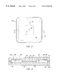
- FIG. 1 is a cross-sectional view of a heat spreader body 20 formed with a first planar body 22 , in the form of a semiconductor package, and a second planar body 21 , in the form of a lid.
- the semiconductor package 22 is a standard pin grid array package with a semiconductor void 24 , which includes bond shelves 26 .
- a semiconductor 28 At the base of the semiconductor void 24 is a semiconductor 28 .
- Bond wires (not shown) electrically couple the semiconductor 28 to the semiconductor package 22 , which includes internal traces (not shown) with electrical connections to a set of package pins 30 .
- the lid 21 has a physical contour such that when it is attached to the semiconductor package 22 it defines a void with a non-capillary region 32 .
- the non-capillary region 32 includes an adiabatic region 44 and a condenser 46 .
- the void also includes a planar capillary fluid path 50 , which includes an evaporator 51 .
- Heat produced by the semiconductor 28 migrates to the top of the semiconductor package 22 .
- the generated heat is largely applied to the evaporator 51 of the heat spreader 20 .
- Most of the heat is applied to the bottom surface 55 of the evaporator 51 , some of the heat conducts through a heat transfer pillar 53 to heat the top surface 57 of the evaporator 51 .
- Fluid within the evaporator 51 absorbs heat and vaporizes.
- the resultant vapor moves through the adiabatic region 44 where it does not loose or gain heat. It continues to move to the condenser region 46 where it cools and condenses on the interior walls of the device.
- the condensed liquid is then drawn, through capillary fluid action, into the planar capillary fluid path 50 .
- the small dimensions of the device result in liquid being drawn by capillary action from the non-capillary region 32 , in particular the condenser 46 , into the planar capillary fluid path 50 .
- the planar capillary fluid path 50 leads back to the evaporator 51 .
- the two-phase vaporization-condensation cycle repeats itself. This cycle results in heat produced by the semiconductor 28 being distributed over a relatively large area, instead of being localized near the semiconductor 28 .
- the evaporator 51 generally corresponds to the size of the semiconductor 28 .
- the lid 21 generally corresponds to the size of the semiconductor package 22 .
- FIG. 2 is a perspective view of the heat spreader lid 21 .
- the figure illustrates a heat transfer pillar 53 , which is formed on an evaporator surface 57 of an evaporator plateau 60 .
- the evaporator plateau 60 rises from a non-capillary region surface 62 .
- the planar capillary fluid path 50 is also formed above the non-capillary region surface 62 .
- a fluid path bridge 63 links the planar capillary fluid path 50 with the evaporator plateau 60 .
- the planar capillary fluid path 50 effectively includes the fluid path bridge 63 and the evaporator surface 57 of the evaporator plateau 60 .
- the dimensions of the device result in capillary action from the non-capillary region 32 to the planer capillary fluid path 50 .
- This capillary action results regardless of the physical orientation of the device in relation to gravity.
- the device of the invention is not limited in this manner.
- the planar capillary fluid path 50 executes a wicking operation associated with heat pipes.
- the wicking operation does not rely upon a separate structure, such as a screen. Instead, the planar capillary fluid path 50 is formed out of the body of the device. Thus, the expense associated with prior art heat pipes is avoided. In addition, the relatively high hydrodynamic resistance of a discrete wick structure is avoided.
- Another advantage of the disclosed apparatus is that the circumferential motion of fluid in the fluid path 50 is never directly counteracted by the motion of vapor in the evaporator 51 .
- vapor moves one direction and liquid moves in an opposite direction.
- a countercurrent viscous shear force exists between liquid flow and vapor flow, a problem avoided with the embodiment of FIG. 1 .
- the size of the heat spreader 20 substantially conforms to the size of the semiconductor package 22 to which it is attached.
- This feature coupled with the low vertical profile of the device makes it ideal for use with compact electronic equipment.
- the low vertical profile also makes the device ideal for use with other cooling devices, such as fans or finned heat sinks.
- the device of the invention is far more efficient at spreading heat than a solid metal slug of comparable dimensions.
- the heat spreader lid 21 is preferably formed of metal, for example aluminum.
- the heat spreader lid 21 may be soldered or brazed to the semiconductor package 22 .
- the vertical clearance of the region defining the condenser 46 is preferably less than 1.0 mm, preferably between and 0.75 mm and 0.25 mm, and most preferably approximately 0.375 mm.
- the vertical clearance of the region defining the evaporator and the planar capillary fluid path 50 is preferably less than 0.5 mm, preferably between 0.325 and 0.025 mm, most preferably approximately 0.125 mm.
- the device of the invention may be formed by machining, by stamping, chemical etching, chemical depositing or any other technique known in the art.
- the surfaces within the body should he thoroughly cleaned.
- the two halves are preferably brazed.
- standard charging techniques are used to place the fluid within the body.
- a vacuum pump is then used to remove non-condensable gases from the void. This operation is facilitated if the fluid is frozen so that the vacuum pump does not remove the fluid itself. Afterwards, only fluid exists in the void. At this point the pressure within the void is proportional to the vapor pressure of the fluid at the existing temperature.
- the body is then sealed to preserve conditions in the void.
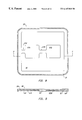
- FIG. 3 is a top view of a heat spreader body portion 21 A.
- the device of FIG. 3 is used with a corresponding heat spreader bottom to form a heat spreader in accordance with the invention.
- both halves of the device are contoured, as opposed to the implementation of FIG. 1, where only one body portion of the device is contoured.
- FIG. 4 illustrates a device 64 constructed with the heat spreader body portion 21 A of FIG. 3 .
- the device 64 includes a corresponding heat spreader bottom 21 B.
- FIG. 4 can be interpreted as a cross-sectional view taken along the line 4 — 4 of FIG. 3 .
- FIG. 4 also illustrates fluid 66 positioned within the evaporator 51 and the fluid path 50 . Further, the figure illustrates the fluid 66 wicking into the fluid path 50 . The figure illustrates that there is very little fluid on the walls of the adiabatic region 44 , and a small amount of fluid on the walls of the condenser 46 .
- FIG. 4A is an exploded view of the device of FIG. 4 .
- the figure illustrates the heat spreader top 21 A and the heat spreader bottom 21 B.
- the figure also illustrates that the fluid 66 fills the capillary fluid path 50 .
- the shape of the fluid 66 is equivalent to the shape of the capillary fluid path 50 .
- FIG. 4A also illustrates a special region 67 .
- the special region 67 conforms to the shape of the non-capillary region 32 .
- the special region 67 can be thought of as the area where vapor exists. As shown in FIG. 4 and as discussed below, in addition to vapor, some fluid does exist in the special region 67 .
- FIG. 5 is a top view of a heat spreader lid 68 .
- the heat spreader lid 68 of FIG. 5 includes an evaporator surface 57 with extended edge surface elements 72 . Since vapor can only leave the evaporator surface 57 at an edge, the configuration of FIG. 5 provides an extended surface into the non-capillary region 32 to facilitate vapor entry.
- FIG. 5 also illustrates a capillary fluid path 50 with extended edge surface elements 76 .
- the extended edge surface elements 76 facilitate the capillary movement of fluid from the non-capillary region 32 to the fluid path 50 .
- a tapered surface between the extended edge surface elements 76 and the condenser non-capillary region 32 is preferable to facilitate capillary fluid movement.
- all embodiments of the invention avoid abrupt surface transitions.
- FIG. 6 illustrates an alternate heat spreader body 80 formed in accordance with the invention.
- the body 80 includes an evaporator plateau surface 57 connected to a fluid path bridge 63 , which leads to a capillary fluid path 50 .
- the capillary fluid path 50 includes extended surface elements in the form of peninsulas 84 .
- the peninsulas 84 are larger than the extended surface elements 76 of FIG. 5, but they serve the same purpose of facilitating the capillary movement of fluid from the non-capillary region 32 to the capillary fluid path 50 .
- FIG. 7 is a cross-sectional view of the device 80 taken along the line 7 — 7 of FIG. 6 .
- the capillary path 50 may be observed on either end of the figure.
- the peninsulas 84 may also be observed between non-capillary regions 32 .
- the device of FIGS. 6 and 7 is a discrete component.
- the total vertical height of the device of FIG. 7 is less than 2.0 mm, preferably approximately 1.5 mm.
- the vertical height of the non-capillary region 32 is consistent with the previously described embodiment.
- the vertical height associated with the path 50 is consistent with the previously described embodiment.
- FIG. 8 is a top view of a dual heat source heat spreader body 90 .
- the device 90 includes a first evaporator surface 57 A and a second evaporator surface 57 B.
- the first evaporator surface 57 A is positioned over a first heat source, such as a semiconductor (not shown), while the second evaporator surface 57 B is positioned over a second semiconductor (not shown).
- a first fluid path bridge 63 A attaches the first evaporator surface 57 A to the planar capillary fluid path 50
- a second fluid path bridge 63 B attaches the first evaporator surface 57 A to the second evaporator surface 57 B.
- a single non-capillary region 32 serves both evaporator regions defined by the evaporator surfaces 57 A, 57 B.
- the non-capillary region 32 has an open path between the two sides of the evaporator surfaces 57 A, 57 B.
- FIG. 9 is a cross-sectional view taken along the line 9 — 9 of FIG. 8 .
- FIG. 9 illustrates the planar capillary fluid path 50 at either end of the body 90 .
- the figure also illustrates the first evaporator surface 57 A positioned between non-capillary regions 32 and the second evaporator evaporator surface 57 B positioned between non-capillary regions 32 .
- FIG. 10 illustrates a quad heat source heat spreader body 100 .
- the body 100 is used in connection with a semiconductor package that houses four semiconductors.
- the body 100 includes a first evaporator surface 57 A, a second evaporator surface 57 B, a third evaporator surface 57 C, and a fourth evaporator surface 57 D.
- First, second, third, and fourth fluid path bridges 63 A, 63 B, 63 C, and 63 D are used to link the evaporator plateaus to the planar capillary fluid path 50 .
- the non-capillary region 32 includes support pillars 102 .
- the support pillars 102 operate as heat transfer pillars.
- the support aspect of the pillars 102 is important to prevent collapse of the non-capillary region 32 under vacuum conditions.
- FIG. 11 is a cross-sectional view taken along the line 11 — 11 of FIG. 10 .
- the figure illustrates the planar capillary fluid path 50 , the evarporator surfaces 57 C and 57 D, the non-capillary region 32 , and the support pillar 102 .
- FIG. 12 is another embodiment of a heat spreader body 110 formed in accordance with the invention.
- the heat spreader body 110 is positioned on a semiconductor package 111 .
- a finned heat sink 114 is positioned on the body 110 .
- the finned heat sink 114 includes a horizontal surface 116 supporting vertical fins 118 .
- the heat spreader body 110 includes a sloping planar surface 112 extending from the evaporator 51 to the condenser 46 of the non-capillary region 32 .
- the sloping planar surface 112 may be configured as a frustum of a cone. Liquid in the condenser 46 is drawn back to the evaporator 51 by the capillary action of the sloping planar surface 112 . That is, capillary action draws fluid from the relatively larvae vertical clearance of the condenser 46 into the relatively small vertical clearance of the evaporator 51 .
- this embodiment of the invention does not have a perimeter planar capillary fluid path.
- fluid is condensed in the non-capillary region 32 and is then drawn by capillarity into the evaporator 57 , without the use of a fluid capillary path bridge.
- the advantage of this embodiment is that the fluid will be drawn into the evaporator 51 through multiple naturally-formed fluid capillary paths on surface 112 .
- FIG. 13 illustrates the heat spreader body 110 of FIG. 12 in a vertical position with respect to gravity.
- the figure further illustrates the capillary action of a fluid within the body.
- Capillary action causes the fluid 120 to surround the heat transfer pillar 53 .
- capillary action causes an upward extension of fluid 121 along the walls of the body 110 , resulting in a concave fluid shape 122 .
- FIG. 13 illustrates the directional insensitivity of the device of the invention, this feature is an important benefit of the invention.
- FIG. 14 is a cross-sectional view of still another heat spreader body 130 in accordance with the invention.
- the sloping planar surface 112 results in a large vertical clearance at the non-capillary region 32 , which is proximately positioned to the evaporator 51 .
- the large vertical clearance at the non-capillary region 32 results in a relatively low vapor pressure adjacent to the evaporator 51 to facilitate the vaporization of fluid in the evaporator 51 .
- the sloping planar surface 112 extends to a planar capillary fluid path 50 at the perimeter of the body 130 .
- the shape of the planar capillary fluid path 50 is shown in FIG. 3 .
- a gentle slope exists between the path 50 and the non-capillary region 32 .
- FIG. 15 is a cross-sectional view of a heat spreader body 150 that integrally incorporates heat sink fins 152 .
- the heat spreader body 150 is for use with a multi-chip semiconductor package 140 , which houses a first semiconductor 28 A and a second semiconductor 28 B.
- the body 150 includes a first heat transfer pillar 53 A surrounded by an evaporator 51 and a non-capillary region 32 .
- the body includes a second heat transfer pillar 53 B surrounded by an evaporator 51 and a non-capillary region 32 .
- a sloping surface is used between the evaporator 51 and the non-capillary region 32 , and thereby enjoys the previously described advantages.
- FIG. 15 further illustrates a fan 154 , including fan blades 156 , positioned on top of the heat sink fins 152 .
- the positioning of a fan 154 on or within heat sink fins 152 is known in the art.
- the present invention facilitates this practice by providing a low vertical profile mechanism to distribute heat from the center of a semiconductor package to the edge of a semiconductor package where the fan performs the most active cooling.
- FIG. 16 illustrates the body 150 of FIG. 15 in a vertical position.
- the figure also illustrates the fluid within the body 150 .
- Capillary action within the void of the body 150 causes fluid to surround the two heat transfer pillars 53 A and 53 B.
- the capillary action toward the heat transfer pillars 53 A and 53 B will result in multiple natural capillary paths into the evaporator 51 .
- FIG. 17 illustrates a “radial” heat spreader embodiment of the invention.
- the term “radial” refers to the contour of the non-capillary region 32 , which exists at the center of the device and extends from the center in sixteen different directions, in a radial pattern.
- the fluid capillary path 50 exists on the perimeter of the device and extends to the center of the device with sixteen different legs 162 .
- the advantages of this embodiment are the numerous fluid capillary path 50 and non-capillary region 32 edges and the fact that vapor can easily migrate to practically any region of the radial non-capillary region 32 . Similarly, there are many fluid capillary path legs back to the center of the device.
- FIG. 18 is a cross-sectional view of the device of FIG. 17 taken along the line 18 — 18 .
- the figure shows the non-capillary region 32 at the center of the structure.
- the figure shows two fluid capillary paths 50 extending into the non-capillary region 32 .
- Liquid evaporates at the end of these fluid capillary paths 50 and enters the non-capillary region 32 . Then, in most cases, the vapor migrates out to the perimeter regions of the non-capillary region 32 .
- FIG. 18 also illustrates heat transfer pillars 53 . As in previous embodiments, these pillars 53 also operate as support structures.
- FIG. 19 is an enlarged view of the center region 164 shown in FIG. 18 .
- FIG. 19 illustrates the non-capillary region 32 , the end of the fluid capillary paths 50 , and the heat transfer pillars 53 positioned on the fluid capillary paths 50 .
- FIG. 20 is a side-view of a top body portion that is used for connection to the bottom body portion shown in FIG. 16 .
- FIG. 20 illustrates a recessed region for forming the non-capillary region 32 .
- the figure illustrates the ceiling portion of the fluid capillary paths 50 and heat transfer pillars 53 , which are mated with the heat transfer pillars 53 shown in FIG. 18 .
- FIG. 21 is a top view of the bottom body portion of a “circle array” heat spreader apparatus 170 in accordance with an embodiment of the invention.
- the non-capillary region 32 is in the form of a large number of discrete circular wells 164 .
- the fluid capillary path 50 surrounds each of the non-capillary regions 164 .
- FIG. 21 also illustrates a large number of heat transfer pillars 53 .
- This embodiment of the invention is advantageous because it allows fluid to easily migrate to almost any region of the structure.
- the embodiment provides a large number of edge surfaces for fluid to evaporate from the fluid capillary path 50 and to return to the fluid capillary path 50 .
- the structure has a “universal” configuration that is effective with a single chip package, a dual chip package, or any other type of multi-chip module.
- FIG. 22 is a side view taken along the line 22 — 22 of FIG. 21 .
- the figure shows different non-capillary regions 164 surrounded by segments of the fluid capillary path 50 .
- the figure also illustrates heat transfer pillars 53 positioned in the fluid capillary path 50 .
- FIG. 23 is an enlarged view of the region 172 of FIG. 22 .
- FIG. 23 illustrates a non-capillary region 164 surrounded by a fluid capillary path 50 , which includes heat transfer pillars 53 .
- FIG. 24 is a top body portion 174 corresponding to the bottom body portion 170 of FIG. 21 .
- the top body portion 174 is configured to mate with the bottom body portion 170 .
- the top body portion 174 includes a fluid capillary path ceiling 50 with heat transfer pillars 53 for alignment with the same elements on the bottom body portion.
- FIG. 25 is a top view of the bottom body portion of a “square matrix” heat spreader apparatus 180 in accordance with an embodiment of the invention.
- the fluid capillary path 50 is shaped like a grid and discrete square non-capillary regions 166 punctuate the grid.
- the embodiment also includes heat transfer pillars 53 .
- FIG. 26 is a side view of the apparatus 180 taken along the line 26 — 26 of FIG. 25 .
- the figure illustrates the fluid capillary path 50 surrounding different non-capillary regions 166 .
- FIG. 27 is an enlarged view of the region 182 of FIG. 26 .
- FIG. 27 illustrates fluid capillary paths 50 surrounding a non-capillary region 166 .
- the figure also illustrates a heat transfer pillar 53 .
- a perimeter plateau 184 for connection with a lid is also illustrated.
- FIG. 28 illustrates a lid 185 for attachment to the apparatus 180 of FIG. 25 .
- the lid 185 includes a fluid capillary path lid portion 50 with heat transfer pillars 53 , which mate with the heat transfer pillars 53 of FIG. 25 .
- FIGS. 25 - 28 An advantage of the embodiment of the invention illustrated in FIGS. 25 - 28 is the ability of fluid to move in linear paths across the entire surface area of the device.
- the square configuration provides a relatively large amount of edge area for evaporated fluid to escape the fluid capillary path 50 and for condensed fluid to return to the fluid capillary path 50 .
- the device of FIGS. 25 - 28 has a universal configuration that allows it to be effectively used with a variety of heat source distribution schemes.
- FIG. 29 illustrates another heat spreader 200 in accordance with the invention.
- the heat spreader 200 includes non-capillary regions of varying size.
- the figure illustrates small patterned non-capillary regions 202 , larger patterned non-capillary regions 204 , and still larger patterned non-capillary regions 206 .
- the patterned non-capillary regions are generally square in FIG. 29, but other patterns, such as circles or triangles may also be used.
- FIG. 30 is a cross-sectional view taken alone the line 30 — 30 of FIG. 29 .
- the figure illustrates non-capillary regions 202 - 206 of varying sizes. Heat transfer pillars interrupt the different non-capillary regions so the different non-capillary regions are somewhat difficult to identify. This effect is more fully appreciated with reference to FIG. 31 .
- FIG. 31 is an enlarged view of the region 208 of FIG. 30 .
- FIG. 31 illustrates that corresponding heat transfer pillars 53 from two sides of the body meet to form a continuous pillar structure.
- these pillars are useful as condensing surfaces. In other words, they are useful to form additional condensing area for vaporized fluid.
- a contoured surface in the non-capillary regions may also be used to provide additional condensing area for the vaporized fluid.
- FIG. 32 is a cross-sectional view taken along the line 32 — 32 of FIG. 29 .
- the figure illustrates non-capillary regions 202 - 206 of varying size. Note that in this figure the different non-capillary regions are not divided-up by heat transfer pillars 53 .
- FIG. 33 is an enlarged view of the region 210 of FIG. 32 .
- FIG. 33 illustrates evaporator regions 51 formed between non-capillary regions 202 . Observe once again that this figure is taken along a line that does not include heat transfer pillars 53 .
- FIG. 34 illustrates another heat spreader 220 in accordance with the invention.
- the heat spreader 220 includes a non-capillary region 32 surrounded by a capillary fluid path 50 .
- the capillary fluid path 50 includes extended surface elements 222 .
- the capillary fluid path 50 leads to a capillary fluid path bridge 223 , which terminates in an evaporator plateau 224 .
- the evaporator plateau 224 has a set of non-capillary regions 226 .
- each non-capillary region 226 is in the form of a triangle.
- FIG. 34 illustrates that different implementations of the disclosed invention may be combined to construct an optimal device for a particular application.
- FIG. 35 is a plan view of another embodiment of the invention.
- the device 240 of FIG. 35 generally corresponds to the device 160 of FIG. 17 .
- the edges 244 of the capillary fluid path 50 in a heat generating region 242 are treated to become nucleation surfaces.
- the nucleation edges 244 have been treated to promote boiling.
- the nucleation surface is generally a roughened surface.
- the surface may be formed by sandblasting, laser etching or other technique that leaves a rough surface or a surface with small pockets in it.
- FIG. 36 illustrates a device 250 with nucleation edges along all of the capillary fluid path surfaces 50 .
- the device 260 of FIG. 37 illustrates that both the non-capillary region 32 and the entire fluid capillary path 50 may be formed with a nucleation surface 262 .
- This embodiment is used for ease of manufacturing. A problem with this embodiment is that some nucleation surfaces may cause resistance in the fluid capillary path 50 .
- FIG. 38 is a perspective view of another embodiment of the invention.
- the device 270 of FIG. 38 has a pedestal 272 so that the remaining portion of the heat spreader 270 clears any objects adjacent to a heat generating surface.
- the semiconductor package 274 includes a set of on-board capacitors 276 .
- the pedestal 272 is used to clear the on-board capacitors 276 .
- the pedestal 272 is integrally formed with the remaining portion of the device 270 .
- the pedestal 272 may be solid metal.
- FIG. 39 is a perspective view of another embodiment of the invention.
- the heat spreader 280 is punctured with apertures 282 .
- the apertures 282 allow protruding devices, such as on-board capacitors 276 of the semiconductor package 274 , to extend through the heat spreader 280 .
- FIG. 40 is a perspective view of a heat spreader 290 formed in accordance with another embodiment of the invention.
- the heat spreader 290 is positioned on semiconductor package 292 , which includes on-board capacitors 294 .
- the heat spreader 290 extends from the surface of the semiconductor package 292 into a cooling region. For example, if the semiconductor package 292 is positioned in a lap top computer, then the heat spreader 290 may extend beyond the semiconductor package 292 underneath the keyboard of the lap top computer.
- the interior portion of the heat spreader 290 includes a capillary fluid path and non-capillary regions as described above.
- the heat spreader 290 also includes heat fins 296 .
- the heat fins are not part of the interior portion of the heat spreader 290 ; that is, they do not have fluid circulating in them. Observe that the heat fins 296 are formed in the same plane as the heat spreader 290 . This configuration is in contrast to prior art devices where the heat fins are orthogonal to the heat spreading surface.
- FIG. 41 is a perspective view of a heat spreader 300 formed in accordance with another embodiment of the invention.
- the heat spreader 300 is positioned on a semiconductor package 292 , which includes on-board capacitors 294 .
- the heat spreader 300 includes a curved or bent region 302 , which terminates in an orthogonal surface 304 . Fluid circulates in capillary fluid path and non-capillary regions of the device 300 . In particular, fluid continuously circulates from the horizontal region of the device 300 , through the bend 302 , and through the orthogonal surface 304 .
- the device 300 also includes heat fins 306 . Selected heat fins 306 include apertures 308 , which may be used to attach a fan (not shown) to the orthogonal surface 304 .
- planar capillary fluid path is a continuous surface. That is, it is continuous in the sense that the fluid can move over the entire surface. In other words, fluid can move from any region on the surface to any other region on the surface.
- substantially square refers to a length-to-width ratio of approximately 20:1, more preferably of approximately 2:1, and most preferably of approximately 1:1.
- Most prior art heat pipes and thermosiphons are configured as tubes.
- the invention is unique in that the capillary fluid movement is established by a planar capillary defined in two adjacent horizontal planes.
- capillary fluid movement is typically established through grooves formed in a surface.
- small vertical walls are formed in a horizontal surface to establish capillary fluid movement.
- Vertical surfaces are not used in the present invention to establish capillary fluid movement. Instead, capillary fluid movement is established by the top (ceiling) and bottom (floor) surfaces of the planar capillary path.
- the performance factor is normalized with respect to copper/tungsten. All heat spreaders measure 71.0 mm ⁇ 71.0 mm ⁇ 1.0 mm. All heat spreaders had a 19.0 mm ⁇ 19.0 mm square heat source centered on one side, and a 7.0 mm wide finned heat sink around the perimeter of the opposing side.
- the invention was implemented with molybdenum and included a non-capillary region with a depth of 0.375 mm and a capillary path with a depth of 0.125 mm. The device was charged with 0.329 cc of water at a pressure of 14 millibars at 25° C. Better performance results are realized with a more rigorous charging procedure. In general, the apparatus of the invention should be charged to an overfill condition of approximately 20%.
- the liquid that does not fit in the fluid capillary path when the fluid capillary path is filled should constitute approximately 20% of the total liquid within the device.
- the invention is implemented by using 0.007 cc of fluid per cm 2 of surface area of the device.
- the outstanding thermal conductivity characteristics of the apparatus of the invention allows the invention to be implemented in a variety of materials.
- the particular material used to implement the invention is not crucial from a thermal conductivity standpoint. Instead, the material may be selected on the basis of cost, coefficient of thermal expansion, or other factors.
- One low cost implementation of the invention is in plastic, provided a hermetic seal is supplied.
- the fluid within the planar capillary fluid path moves very quickly during steady state operation.
- the fluid moves at a speed of between 25 and 200 mm/s. This speed is dramatically faster than any device that uses a wick. This characteristic of the invention is partly responsible for the outstanding thermal distribution performance.
Abstract
A heat spreading apparatus includes a first planar body for attachment to a heat generating surface which results in a hot region and a cool region on the first planar body. A second planar body connected to the first planar body is used to define a void between the first planar body and the second planar body. The void includes a planar capillary path and a non-capillary region. A fluid positioned within the void distributes heat by vaporizing the fluid from the planar capillary path in the hot region, condensing the fluid in the non-capillary region in the cool region, and moving from the non-capillary region to the planar capillary path in the hot region through capillarity.
Description
This invention relates generally to a heat distribution device, such as for use with a microprocessor or other microelectronic device. More particularly, this invention relates to a thin, planar heat spreader that distributes heat through the use of a planar capillary fluid path.
Semiconductors are continuously diminishing in size. Corresponding to this size reduction is an increase in the power densities of semiconductors. This, in turn, creates heat proliferation problems which must be resolved because excessive heat will degrade semiconductor performance.
Heat pipes and thermosiphons have been used to cool semiconductors. Both heat pipes and thermosiphons operate on a closed two-phase cycle that utilizes the latent heat of vaporization to transfer heat.
Thermosiphons are typically implemented as a tube which encloses a fluid. When used in relation to a semiconductor, for instance a microprocessor, the first end of the thermosiphon, called a vaporizer or evaporator, is attached to a heat generating surface of the semiconductor. The second end of the thermosiphon, referred to as a condenser, vertically extends from the semiconductor where it is cooled by ambient air.
In a first cycle, the heat from the semiconductor vaporizes the fluid within the thermosiphon. During this vaporization process, the fluid vapor absorbs a quantity of heat called the latent heat of vaporization. The vapor formed in the vaporizer is at a higher temperature and hence higher pressure than the vapor at the condenser. Thus, the vapor flows from the evaporator to the condenser.
In a second cycle, the vapor condenses on the condenser walls of the thermosiphon. The condensation operation results in the release of heat. As a result, heat is moved from the evaporator to the condenser. Gravitational forces then cause the condensate in the condenser to flow back to the evaporator. The two-cycle process is then repeated.
Although the inside surface of a thermosiphon may occasionally be lined with grooves or a porous structure to promote the return of the condensate to the evaporator or increase the heat transfer coefficient, thermosiphons principally rely upon local gravitational force to return liquid to the evaporator. By definition, then, for proper operation, the evaporator of a thermnosiphon must be located below the condenser.
Heat pipes operate on the same principle as thermosiphons. One distinguishing feature of heat pipes is that they utilize some sort of discrete wicking structure to promote the flow of liquid from the condenser to the evaporator. The wicking structure allows heat pipes to be used in a horizontal orientation relative to gravity, or even with the evaporator oriented against gravity, although the efficiency of the device varies greatly with different physical orientations. For example, if the device is oriented against gravity, its performance is reduced by approximately one-half. Thus, it is the dependence of the local gravitational field to promote the flow of the liquid from the condenser to the evaporator that differentiates thermosiphons from heat pipes.
The problem with using thermiosiphons with microprocessors is that thermosiphons require a vertical orientation with respect to gravity. This results in a high profile device. As a result, thermosiphons are difficult to use in compact electronic equipment such as palm, notebook, lap, desktop computers, and power supplies.
Another problem with the use of thermosiphons is that they are directionally sensitive. That is, they must be oriented such that gravity forces condensed fluid back to the evaporator. Microprocessor vendors do not know how a computer user will position a computer. For instance, some computers are placed horizontally on desk tops, while others are vertically mounted on floors. A theimosiphon can only operate with a single predetermined physical orientation to gravity.
While heat pipes are not as directionally sensitive, as thermosiphons, they still have the disadvantage of requiring a discrete wick structure. The discrete wick structure is typically formed of a screen, sintered metal, or as a set of axial grooves. A discrete wick structure adds manufacturing expense and otherwise mitigates against high volume manufacturing of heat pipes. In addition, a discrete wick structure, such as a screen, produces a relatively high hydrodynamic resistance. Thus, it would be highly desirable to provide a heat transfer device that is not directionally sensitive and does not require a high hydrodynamic resistance wick structure. Such a device should have a low vertical profile to insure that it can be readily incorporated into a variety of compact electronic equipment.
Another type of device that is commonly used to reduce the heat problems associated with semiconductors is a finned heat sink. A finned heat sink has a horizontal surface that is attached to a heat generating semiconductor surface and a set of fins vertically extending from the horizontal surface. The fins are cooled by ambient air. Thus, heat at the horizontal surface conductively migrates to the fins. Typically, heat is only generated in a few regions of the horizontal surface of a finned heat sink. Thus, only the fins corresponding to those few regions perform most of the cooling. To mitigate the problem of localized heat, a relatively thick heat slug can be used to improve heat distribution. The problem with this approach is that it substantially increases the vertical profile of the device. In addition, the heat slug is heavy and relatively expensive. Consequently, it would be highly desirable to provide a device that evenly distributes heat along the horizontal surface of a finned heat sink, without substantially increasing the vertical profile of the semiconductor package. Such a device would allow all of the fins of the heat sink to dissipate heat. Thus, the efficiency of the finned heat sink would be improved.
Fans have also been used to reduce the heat problems associated with heat generating surfaces, such as semiconductors. There is typically uneven heat distribution on the surface or surfaces from which a fan removes heat. A fan operating in these conditions is not as efficient as a fan removing heat from a surface with an even heat distribution. Moreover, when a fan is used on a heat generating surface, thermodynamic studies indicate that most air movement produced by the fan is applied at the perimeter of the fan. Thus, it is extremely important to convey heat to the perimeter of a heat generating surface. In view of the foregoing, it would be highly desirable to provide a device that evenly distributes heat to a surface or surfaces exposed to a fan. Optimally, such a device would have a low vertical profile to insure its compatibility with compact electronic equipment.
A heat spreading apparatus includes a first planar body for attachment to a heat generating surface resulting in a hot region and a cool region on the first planar body. A second planar body connected to the first planar body is used to define a void between the first planar body and the second planar body. The void includes a planar capillary path and a non-capillary region. A fluid positioned within the void distributes heat by vaporizing the fluid from the planar capillary path in the hot region, condensing the fluid in the non-capillary region in the cool region, and moving from the non-capillary region to the planar capillary path in the hot region through capillarity.
The body is extremely thin, typically less than 1.5 millimeters. Nevertheless, its heat distribution characteristics are much better than existing metal heat slurs with far larger vertical profiles. Thus, the device is ideally suited for compact electronic equipment and for use with other cooling, devices, such as finned heat sinks or fans.
While the device operates in a two-phase cycle, like a thermosiphon or heat pipe, it does not have some of the key characteristics of such devices. Unlike a thermosiphon, the device of the invention is orientation insensitive. Unlike a heat pipe, which has a discrete wick, such as a screen or axial grooves, the invention relies upon a planar capillary fluid path formed in the body of the device. The geometry of the planar capillary fluid path avoids the relatively high hydrodynamic resistance wick of existing heat pipes. In addition, the configuration of the capillary fluid path, in certain embodiments, eliminates the countercurrent viscous shear force between liquid flow in the condenser and vapor flow in the evaporator, a problem associated with existing heat pipes and thermosiphons. Finally, the configuration of the device facilitates low-cost, high volume manufacturing.
For a better understanding of the nature and objects of the invention, reference should be made to the following detailed description taken in conjunction with the accompanying drawings, in which:
FIG. 1 is a cross-sectional view of a heat spreader formed in accordance with one embodiment of the invention.
FIG. 2 is a perspective view of a portion of the heat spreader shown in FIG. 1.
FIG. 3 is a top view of a portion of a heat spreader in accordance with an embodiment of the invention.
FIG. 4 is a cross-sectional view taken along the line 4-4 of FIG. 3, showing fluid within the heat spreader.
FIG. 4A is an exploded view of the apparatus of FIG. 4.
FIG. 5 is an alternate configuration of a portion of a heat spreader in accordance with an embodiment of the invention.
FIG. 6 is a top view of a heat spreader with an extended surface planar capillary fluid path, in accordance with one embodiment of the invention.
FIG. 7 is a cross-sectional view taken along the line 7—7 of FIG. 6.
FIG. 8 is a top view of a dual heat source heat spreader body in accordance with another embodiment of the invention.
FIG. 9 is a cross-sectional view taken along the line 9—9 of FIG. 8.
FIG. 10 is a top view of a quad heat source heat spreader body in accordance with another embodiment of the invention.
FIG. 11 is a cross-sectional view taken along the line 11—11 of FIG. 10.
FIG. 12 is a cross-sectional view of an alternate heat spreader body configuration in accordance with the invention.
FIG. 13 illustrates the fluid pattern within the heat spreader body of FIG. 12 when it is vertically oriented with respect to gravity.
FIG. 14 is a cross-sectional view of an alternate heat spreader body configuration in accordance with the invention.
FIG. 15 is a cross-sectional view of an alternate dual heat source heat spreader body in accordance with the invention.
FIG. 16 illustrates the fluid pattern within the heat spreader body of FIG. 15 when it is vertically oriented with respect to gravity.
FIG. 17 is a top view of the bottom body portion of a “radial” heat spreader configuration in accordance with an embodiment of the invention.
FIG. 18 is a cross-sectional view taken along the line 18—18 of FIG. 17.
FIG. 19 is an enlarged view of a portion of the apparatus of FIG. 18.
FIG. 20 is a side view of the top body portion to be used with the heat spreader of FIG. 19.
FIG. 21 is a top view of the bottom body portion of a “circle array” heat spreader configuration in accordance with an embodiment of the invention.
FIG. 22 is a cross-sectional view taken along the line 22—22 of FIG. 21.
FIG. 23 is an enlarged view of a portion of the apparatus of FIG. 22.
FIG. 24 is a side view of the top body portion to be used with the heat spreader of FIG. 21.
FIG. 25 is a top view of the bottom body portion of a “square matrix” heat spreader configuration in accordance with an embodiment of the invention.
FIG. 26 is a cross-sectional view taken along the line 26—26 of FIG. 25.
FIG. 27 is an enlarged view of a portion of the apparatus of FIG. 26.
FIG. 28 is a side view of the top body portion to be used with the heat spreader of FIG. 24.
FIG. 29 is a top view of the bottom body portion of a “varying size square matrix” heat spreader configuration in accordance with an embodiment of the invention.
FIG. 30 is a cross-sectional view taken along the line 30—30 of FIG. 29.
FIG. 31 is an enlarged view of a portion of the apparatus of FIG. 30.
FIG. 32 is a cross-sectional view taken along the line 32—32 of FIG. 29.
FIG. 33 is an enlarged view of a portion of the apparatus of FIG. 32.
FIG. 34 is an alternate embodiment of the invention which includes an evaporator plateau with triangular condenser regions formed therein.
FIG. 35 is a plan view of an embodiment of the invention which includes perimeter nucleation site surfaces in selected regions of the capillary fluid path.
FIG. 36 is a plan view of an embodiment of the invention which includes perimeter nucleation site surfaces throughout the capillary fluid path.
FIG. 37 is a plan view of an embodiment of the invention which includes nucleation site surfaces over capillary regions and non-capillary regions.
FIG. 38 is a perspective view of an embodiment of the invention with a pedestal member used to provide clearance over capacitors formed on the top of a semiconductor package.
FIG. 39 is a perspective view of an embodiment of the invention with apertures to provide clearance for capacitors formed on the top of a semiconductor package.
FIG. 40 is a perspective view of an embodiment of the invention wherein the apparatus includes an extended surface area and planar heat sink fins formed integrally within the plane defined by the apparatus.
FIG. 41 is a perspective view of an embodiment of the invention wherein the apparatus includes a curved body and planar heat sink fins formed integrally within the plane defined by the apparatus.
Like reference numerals refer to corresponding parts throughout the several views of the drawings.
FIG. 1 is a cross-sectional view of a heat spreader body 20 formed with a first planar body 22, in the form of a semiconductor package, and a second planar body 21, in the form of a lid. The semiconductor package 22 is a standard pin grid array package with a semiconductor void 24, which includes bond shelves 26. At the base of the semiconductor void 24 is a semiconductor 28. Bond wires (not shown) electrically couple the semiconductor 28 to the semiconductor package 22, which includes internal traces (not shown) with electrical connections to a set of package pins 30.
The lid 21 has a physical contour such that when it is attached to the semiconductor package 22 it defines a void with a non-capillary region 32. The non-capillary region 32 includes an adiabatic region 44 and a condenser 46. The void also includes a planar capillary fluid path 50, which includes an evaporator 51.
Heat produced by the semiconductor 28 migrates to the top of the semiconductor package 22. The generated heat is largely applied to the evaporator 51 of the heat spreader 20. Most of the heat is applied to the bottom surface 55 of the evaporator 51, some of the heat conducts through a heat transfer pillar 53 to heat the top surface 57 of the evaporator 51. Fluid within the evaporator 51 absorbs heat and vaporizes. The resultant vapor moves through the adiabatic region 44 where it does not loose or gain heat. It continues to move to the condenser region 46 where it cools and condenses on the interior walls of the device. The condensed liquid is then drawn, through capillary fluid action, into the planar capillary fluid path 50. That is, the small dimensions of the device, discussed in detail below, result in liquid being drawn by capillary action from the non-capillary region 32, in particular the condenser 46, into the planar capillary fluid path 50. The planar capillary fluid path 50 leads back to the evaporator 51. Thus, the two-phase vaporization-condensation cycle repeats itself. This cycle results in heat produced by the semiconductor 28 being distributed over a relatively large area, instead of being localized near the semiconductor 28.
Observe that the evaporator 51 generally corresponds to the size of the semiconductor 28. Similarly, the lid 21 generally corresponds to the size of the semiconductor package 22.
The operation of the invention is more fully appreciated with reference to FIG. 2, which is a perspective view of the heat spreader lid 21. The figure illustrates a heat transfer pillar 53, which is formed on an evaporator surface 57 of an evaporator plateau 60. The evaporator plateau 60 rises from a non-capillary region surface 62. The planar capillary fluid path 50 is also formed above the non-capillary region surface 62. A fluid path bridge 63 links the planar capillary fluid path 50 with the evaporator plateau 60. Thus, the planar capillary fluid path 50 effectively includes the fluid path bridge 63 and the evaporator surface 57 of the evaporator plateau 60.
Those skilled in the art will recognize a number of unique attributes associated with the present invention. As indicated above, the dimensions of the device result in capillary action from the non-capillary region 32 to the planer capillary fluid path 50. This capillary action results regardless of the physical orientation of the device in relation to gravity. Thus, unlike a thermosiphon which must be used with a single orientation to gravity, the device of the invention is not limited in this manner.
The planar capillary fluid path 50 executes a wicking operation associated with heat pipes. However, unlike existing heat pipes, the wicking operation does not rely upon a separate structure, such as a screen. Instead, the planar capillary fluid path 50 is formed out of the body of the device. Thus, the expense associated with prior art heat pipes is avoided. In addition, the relatively high hydrodynamic resistance of a discrete wick structure is avoided.
Another advantage of the disclosed apparatus is that the circumferential motion of fluid in the fluid path 50 is never directly counteracted by the motion of vapor in the evaporator 51. In most heat pipes and thermosiphons, vapor moves one direction and liquid moves in an opposite direction. As a result, in these prior art devices a countercurrent viscous shear force exists between liquid flow and vapor flow, a problem avoided with the embodiment of FIG. 1.
As shown in FIG. 1, the size of the heat spreader 20 substantially conforms to the size of the semiconductor package 22 to which it is attached. This feature, coupled with the low vertical profile of the device makes it ideal for use with compact electronic equipment. The low vertical profile also makes the device ideal for use with other cooling devices, such as fans or finned heat sinks. As demonstrated below, the device of the invention is far more efficient at spreading heat than a solid metal slug of comparable dimensions.
The heat spreader lid 21 is preferably formed of metal, for example aluminum. The heat spreader lid 21 may be soldered or brazed to the semiconductor package 22. The vertical clearance of the region defining the condenser 46 is preferably less than 1.0 mm, preferably between and 0.75 mm and 0.25 mm, and most preferably approximately 0.375 mm. The vertical clearance of the region defining the evaporator and the planar capillary fluid path 50 is preferably less than 0.5 mm, preferably between 0.325 and 0.025 mm, most preferably approximately 0.125 mm.
The device of the invention may be formed by machining, by stamping, chemical etching, chemical depositing or any other technique known in the art. To insure proper wetting within the heat spreader 20, the surfaces within the body should he thoroughly cleaned. The two halves are preferably brazed. Thereafter, standard charging techniques are used to place the fluid within the body. Typically, a vacuum pump is then used to remove non-condensable gases from the void. This operation is facilitated if the fluid is frozen so that the vacuum pump does not remove the fluid itself. Afterwards, only fluid exists in the void. At this point the pressure within the void is proportional to the vapor pressure of the fluid at the existing temperature. The body is then sealed to preserve conditions in the void.
FIG. 3 is a top view of a heat spreader body portion 21A. The device of FIG. 3 is used with a corresponding heat spreader bottom to form a heat spreader in accordance with the invention. In such a configuration, both halves of the device are contoured, as opposed to the implementation of FIG. 1, where only one body portion of the device is contoured.
FIG. 4 illustrates a device 64 constructed with the heat spreader body portion 21A of FIG. 3. The device 64 includes a corresponding heat spreader bottom 21B. Thus, FIG. 4 can be interpreted as a cross-sectional view taken along the line 4—4 of FIG. 3.
FIG. 4 also illustrates fluid 66 positioned within the evaporator 51 and the fluid path 50. Further, the figure illustrates the fluid 66 wicking into the fluid path 50. The figure illustrates that there is very little fluid on the walls of the adiabatic region 44, and a small amount of fluid on the walls of the condenser 46.
FIG. 4A is an exploded view of the device of FIG. 4. The figure illustrates the heat spreader top 21A and the heat spreader bottom 21B. The figure also illustrates that the fluid 66 fills the capillary fluid path 50. Thus, the shape of the fluid 66 is equivalent to the shape of the capillary fluid path 50. FIG. 4A also illustrates a special region 67. The special region 67 conforms to the shape of the non-capillary region 32. Thus, the special region 67 can be thought of as the area where vapor exists. As shown in FIG. 4 and as discussed below, in addition to vapor, some fluid does exist in the special region 67.
FIG. 5 is a top view of a heat spreader lid 68. The heat spreader lid 68 of FIG. 5 includes an evaporator surface 57 with extended edge surface elements 72. Since vapor can only leave the evaporator surface 57 at an edge, the configuration of FIG. 5 provides an extended surface into the non-capillary region 32 to facilitate vapor entry. FIG. 5 also illustrates a capillary fluid path 50 with extended edge surface elements 76. The extended edge surface elements 76 facilitate the capillary movement of fluid from the non-capillary region 32 to the fluid path 50. A tapered surface between the extended edge surface elements 76 and the condenser non-capillary region 32 is preferable to facilitate capillary fluid movement. Preferably, all embodiments of the invention avoid abrupt surface transitions.
FIG. 6 illustrates an alternate heat spreader body 80 formed in accordance with the invention. The body 80 includes an evaporator plateau surface 57 connected to a fluid path bridge 63, which leads to a capillary fluid path 50. The capillary fluid path 50 includes extended surface elements in the form of peninsulas 84. The peninsulas 84 are larger than the extended surface elements 76 of FIG. 5, but they serve the same purpose of facilitating the capillary movement of fluid from the non-capillary region 32 to the capillary fluid path 50.
FIG. 7 is a cross-sectional view of the device 80 taken along the line 7—7 of FIG. 6. The capillary path 50 may be observed on either end of the figure. The peninsulas 84 may also be observed between non-capillary regions 32.
Unlike the heat spreader lid 21 of FIG. 1, which forms a body with a semiconductor package, the device of FIGS. 6 and 7 is a discrete component. Preferably, the total vertical height of the device of FIG. 7 is less than 2.0 mm, preferably approximately 1.5 mm. The vertical height of the non-capillary region 32 is consistent with the previously described embodiment. Similarly, the vertical height associated with the path 50 is consistent with the previously described embodiment.
FIG. 8 is a top view of a dual heat source heat spreader body 90. The device 90 includes a first evaporator surface 57A and a second evaporator surface 57B. The first evaporator surface 57A is positioned over a first heat source, such as a semiconductor (not shown), while the second evaporator surface 57B is positioned over a second semiconductor (not shown). A first fluid path bridge 63A attaches the first evaporator surface 57A to the planar capillary fluid path 50, while a second fluid path bridge 63B attaches the first evaporator surface 57A to the second evaporator surface 57B. Preferably, a single non-capillary region 32 serves both evaporator regions defined by the evaporator surfaces 57A, 57B. In other words, the non-capillary region 32 has an open path between the two sides of the evaporator surfaces 57A, 57B.
FIG. 9 is a cross-sectional view taken along the line 9—9 of FIG. 8. FIG. 9 illustrates the planar capillary fluid path 50 at either end of the body 90. The figure also illustrates the first evaporator surface 57A positioned between non-capillary regions 32 and the second evaporator evaporator surface 57B positioned between non-capillary regions 32.
FIG. 10 illustrates a quad heat source heat spreader body 100. The body 100 is used in connection with a semiconductor package that houses four semiconductors. The body 100 includes a first evaporator surface 57A, a second evaporator surface 57B, a third evaporator surface 57C, and a fourth evaporator surface 57D. First, second, third, and fourth fluid path bridges 63A, 63B, 63C, and 63D are used to link the evaporator plateaus to the planar capillary fluid path 50. The non-capillary region 32 includes support pillars 102. The support pillars 102 operate as heat transfer pillars. The support aspect of the pillars 102 is important to prevent collapse of the non-capillary region 32 under vacuum conditions.
FIG. 11 is a cross-sectional view taken along the line 11—11 of FIG. 10. The figure illustrates the planar capillary fluid path 50, the evarporator surfaces 57C and 57D, the non-capillary region 32, and the support pillar 102.
FIG. 12 is another embodiment of a heat spreader body 110 formed in accordance with the invention. The heat spreader body 110 is positioned on a semiconductor package 111. A finned heat sink 114 is positioned on the body 110. The finned heat sink 114 includes a horizontal surface 116 supporting vertical fins 118.
The heat spreader body 110 includes a sloping planar surface 112 extending from the evaporator 51 to the condenser 46 of the non-capillary region 32. The sloping planar surface 112 may be configured as a frustum of a cone. Liquid in the condenser 46 is drawn back to the evaporator 51 by the capillary action of the sloping planar surface 112. That is, capillary action draws fluid from the relatively larvae vertical clearance of the condenser 46 into the relatively small vertical clearance of the evaporator 51. Thus, this embodiment of the invention does not have a perimeter planar capillary fluid path. Instead, fluid is condensed in the non-capillary region 32 and is then drawn by capillarity into the evaporator 57, without the use of a fluid capillary path bridge. The advantage of this embodiment is that the fluid will be drawn into the evaporator 51 through multiple naturally-formed fluid capillary paths on surface 112.
FIG. 13 illustrates the heat spreader body 110 of FIG. 12 in a vertical position with respect to gravity. The figure further illustrates the capillary action of a fluid within the body. Capillary action causes the fluid 120 to surround the heat transfer pillar 53. In addition, capillary action causes an upward extension of fluid 121 along the walls of the body 110, resulting in a concave fluid shape 122. FIG. 13 illustrates the directional insensitivity of the device of the invention, this feature is an important benefit of the invention.
FIG. 14 is a cross-sectional view of still another heat spreader body 130 in accordance with the invention. In this embodiment, the sloping planar surface 112 results in a large vertical clearance at the non-capillary region 32, which is proximately positioned to the evaporator 51. The large vertical clearance at the non-capillary region 32 results in a relatively low vapor pressure adjacent to the evaporator 51 to facilitate the vaporization of fluid in the evaporator 51. The sloping planar surface 112 extends to a planar capillary fluid path 50 at the perimeter of the body 130. The shape of the planar capillary fluid path 50 is shown in FIG. 3. However, unlike the embodiment of FIG. 3, in the embodiment of FIG. 13, a gentle slope exists between the path 50 and the non-capillary region 32.
FIG. 15 is a cross-sectional view of a heat spreader body 150 that integrally incorporates heat sink fins 152. The heat spreader body 150 is for use with a multi-chip semiconductor package 140, which houses a first semiconductor 28A and a second semiconductor 28B. The body 150 includes a first heat transfer pillar 53A surrounded by an evaporator 51 and a non-capillary region 32. In addition, the body includes a second heat transfer pillar 53B surrounded by an evaporator 51 and a non-capillary region 32. Once again, a sloping surface is used between the evaporator 51 and the non-capillary region 32, and thereby enjoys the previously described advantages.
FIG. 15 further illustrates a fan 154, including fan blades 156, positioned on top of the heat sink fins 152. The positioning of a fan 154 on or within heat sink fins 152 is known in the art. The present invention facilitates this practice by providing a low vertical profile mechanism to distribute heat from the center of a semiconductor package to the edge of a semiconductor package where the fan performs the most active cooling.
FIG. 16 illustrates the body 150 of FIG. 15 in a vertical position. The figure also illustrates the fluid within the body 150. Capillary action within the void of the body 150 causes fluid to surround the two heat transfer pillars 53A and 53B. As mentioned previously, when in a horizontal orientation to gravity, the capillary action toward the heat transfer pillars 53A and 53B will result in multiple natural capillary paths into the evaporator 51.
FIG. 17 illustrates a “radial” heat spreader embodiment of the invention. The term “radial” refers to the contour of the non-capillary region 32, which exists at the center of the device and extends from the center in sixteen different directions, in a radial pattern. The fluid capillary path 50 exists on the perimeter of the device and extends to the center of the device with sixteen different legs 162. The advantages of this embodiment are the numerous fluid capillary path 50 and non-capillary region 32 edges and the fact that vapor can easily migrate to practically any region of the radial non-capillary region 32. Similarly, there are many fluid capillary path legs back to the center of the device.
FIG. 18 is a cross-sectional view of the device of FIG. 17 taken along the line 18—18. The figure shows the non-capillary region 32 at the center of the structure. Similarly, the figure shows two fluid capillary paths 50 extending into the non-capillary region 32. Liquid evaporates at the end of these fluid capillary paths 50 and enters the non-capillary region 32. Then, in most cases, the vapor migrates out to the perimeter regions of the non-capillary region 32. FIG. 18 also illustrates heat transfer pillars 53. As in previous embodiments, these pillars 53 also operate as support structures.
FIG. 19 is an enlarged view of the center region 164 shown in FIG. 18. FIG. 19 illustrates the non-capillary region 32, the end of the fluid capillary paths 50, and the heat transfer pillars 53 positioned on the fluid capillary paths 50.
FIG. 20 is a side-view of a top body portion that is used for connection to the bottom body portion shown in FIG. 16. FIG. 20 illustrates a recessed region for forming the non-capillary region 32. In addition, the figure illustrates the ceiling portion of the fluid capillary paths 50 and heat transfer pillars 53, which are mated with the heat transfer pillars 53 shown in FIG. 18.
FIG. 21 is a top view of the bottom body portion of a “circle array” heat spreader apparatus 170 in accordance with an embodiment of the invention. In this configuration of the invention, the non-capillary region 32 is in the form of a large number of discrete circular wells 164. The fluid capillary path 50 surrounds each of the non-capillary regions 164. FIG. 21 also illustrates a large number of heat transfer pillars 53. This embodiment of the invention is advantageous because it allows fluid to easily migrate to almost any region of the structure. In addition, the embodiment provides a large number of edge surfaces for fluid to evaporate from the fluid capillary path 50 and to return to the fluid capillary path 50. Further, the structure has a “universal” configuration that is effective with a single chip package, a dual chip package, or any other type of multi-chip module.
FIG. 22 is a side view taken along the line 22—22 of FIG. 21. The figure shows different non-capillary regions 164 surrounded by segments of the fluid capillary path 50. The figure also illustrates heat transfer pillars 53 positioned in the fluid capillary path 50.
FIG. 23 is an enlarged view of the region 172 of FIG. 22. FIG. 23 illustrates a non-capillary region 164 surrounded by a fluid capillary path 50, which includes heat transfer pillars 53.
FIG. 24 is a top body portion 174 corresponding to the bottom body portion 170 of FIG. 21. The top body portion 174 is configured to mate with the bottom body portion 170. Thus, the top body portion 174 includes a fluid capillary path ceiling 50 with heat transfer pillars 53 for alignment with the same elements on the bottom body portion.
FIG. 25 is a top view of the bottom body portion of a “square matrix” heat spreader apparatus 180 in accordance with an embodiment of the invention. In this embodiment, the fluid capillary path 50 is shaped like a grid and discrete square non-capillary regions 166 punctuate the grid. The embodiment also includes heat transfer pillars 53.
FIG. 26 is a side view of the apparatus 180 taken along the line 26—26 of FIG. 25. The figure illustrates the fluid capillary path 50 surrounding different non-capillary regions 166. FIG. 27 is an enlarged view of the region 182 of FIG. 26. FIG. 27 illustrates fluid capillary paths 50 surrounding a non-capillary region 166. The figure also illustrates a heat transfer pillar 53. A perimeter plateau 184 for connection with a lid is also illustrated.
FIG. 28 illustrates a lid 185 for attachment to the apparatus 180 of FIG. 25. The lid 185 includes a fluid capillary path lid portion 50 with heat transfer pillars 53, which mate with the heat transfer pillars 53 of FIG. 25.
An advantage of the embodiment of the invention illustrated in FIGS. 25-28 is the ability of fluid to move in linear paths across the entire surface area of the device. In addition, the square configuration provides a relatively large amount of edge area for evaporated fluid to escape the fluid capillary path 50 and for condensed fluid to return to the fluid capillary path 50. Further, as in the case of the “circular array” configuration of FIGS. 21-24, the device of FIGS. 25-28 has a universal configuration that allows it to be effectively used with a variety of heat source distribution schemes.
FIG. 29 illustrates another heat spreader 200 in accordance with the invention. The heat spreader 200 includes non-capillary regions of varying size. In particular, the figure illustrates small patterned non-capillary regions 202, larger patterned non-capillary regions 204, and still larger patterned non-capillary regions 206. The patterned non-capillary regions are generally square in FIG. 29, but other patterns, such as circles or triangles may also be used.
FIG. 30 is a cross-sectional view taken alone the line 30—30 of FIG. 29. The figure illustrates non-capillary regions 202-206 of varying sizes. Heat transfer pillars interrupt the different non-capillary regions so the different non-capillary regions are somewhat difficult to identify. This effect is more fully appreciated with reference to FIG. 31.
FIG. 31 is an enlarged view of the region 208 of FIG. 30. FIG. 31 illustrates that corresponding heat transfer pillars 53 from two sides of the body meet to form a continuous pillar structure. In addition to providing physical support for the device and operating to conductively move heat from one side of the device to the other, these pillars are useful as condensing surfaces. In other words, they are useful to form additional condensing area for vaporized fluid. A contoured surface in the non-capillary regions may also be used to provide additional condensing area for the vaporized fluid.
FIG. 32 is a cross-sectional view taken along the line 32—32 of FIG. 29. The figure illustrates non-capillary regions 202-206 of varying size. Note that in this figure the different non-capillary regions are not divided-up by heat transfer pillars 53.
FIG. 33 is an enlarged view of the region 210 of FIG. 32. FIG. 33 illustrates evaporator regions 51 formed between non-capillary regions 202. Observe once again that this figure is taken along a line that does not include heat transfer pillars 53.
FIG. 34 illustrates another heat spreader 220 in accordance with the invention. The heat spreader 220 includes a non-capillary region 32 surrounded by a capillary fluid path 50. The capillary fluid path 50 includes extended surface elements 222. The capillary fluid path 50 leads to a capillary fluid path bridge 223, which terminates in an evaporator plateau 224. The evaporator plateau 224 has a set of non-capillary regions 226. In this embodiment, each non-capillary region 226 is in the form of a triangle. FIG. 34 illustrates that different implementations of the disclosed invention may be combined to construct an optimal device for a particular application.
FIG. 35 is a plan view of another embodiment of the invention. The device 240 of FIG. 35 generally corresponds to the device 160 of FIG. 17. However, in FIG. 35, the edges 244 of the capillary fluid path 50 in a heat generating region 242 are treated to become nucleation surfaces. In other words, the nucleation edges 244 have been treated to promote boiling. The nucleation surface is generally a roughened surface. The surface may be formed by sandblasting, laser etching or other technique that leaves a rough surface or a surface with small pockets in it.
FIG. 36 illustrates a device 250 with nucleation edges along all of the capillary fluid path surfaces 50. The device 260 of FIG. 37 illustrates that both the non-capillary region 32 and the entire fluid capillary path 50 may be formed with a nucleation surface 262. This embodiment is used for ease of manufacturing. A problem with this embodiment is that some nucleation surfaces may cause resistance in the fluid capillary path 50.
FIG. 38 is a perspective view of another embodiment of the invention. The device 270 of FIG. 38 has a pedestal 272 so that the remaining portion of the heat spreader 270 clears any objects adjacent to a heat generating surface. For example, the semiconductor package 274 includes a set of on-board capacitors 276. Thus, the pedestal 272 is used to clear the on-board capacitors 276. Preferably, the pedestal 272 is integrally formed with the remaining portion of the device 270. The pedestal 272 may be solid metal.
FIG. 39 is a perspective view of another embodiment of the invention. In this embodiment the heat spreader 280 is punctured with apertures 282. The apertures 282 allow protruding devices, such as on-board capacitors 276 of the semiconductor package 274, to extend through the heat spreader 280.
FIG. 40 is a perspective view of a heat spreader 290 formed in accordance with another embodiment of the invention. The heat spreader 290 is positioned on semiconductor package 292, which includes on-board capacitors 294. The heat spreader 290 extends from the surface of the semiconductor package 292 into a cooling region. For example, if the semiconductor package 292 is positioned in a lap top computer, then the heat spreader 290 may extend beyond the semiconductor package 292 underneath the keyboard of the lap top computer. The interior portion of the heat spreader 290 includes a capillary fluid path and non-capillary regions as described above. The heat spreader 290 also includes heat fins 296. Preferably, the heat fins are not part of the interior portion of the heat spreader 290; that is, they do not have fluid circulating in them. Observe that the heat fins 296 are formed in the same plane as the heat spreader 290. This configuration is in contrast to prior art devices where the heat fins are orthogonal to the heat spreading surface.
FIG. 41 is a perspective view of a heat spreader 300 formed in accordance with another embodiment of the invention. As in the previous embodiment, the heat spreader 300 is positioned on a semiconductor package 292, which includes on-board capacitors 294. The heat spreader 300 includes a curved or bent region 302, which terminates in an orthogonal surface 304. Fluid circulates in capillary fluid path and non-capillary regions of the device 300. In particular, fluid continuously circulates from the horizontal region of the device 300, through the bend 302, and through the orthogonal surface 304. The device 300 also includes heat fins 306. Selected heat fins 306 include apertures 308, which may be used to attach a fan (not shown) to the orthogonal surface 304.
Observe that in each embodiment of the invention, the planar capillary fluid path is a continuous surface. That is, it is continuous in the sense that the fluid can move over the entire surface. In other words, fluid can move from any region on the surface to any other region on the surface.
Another noteworthy aspect of the invention is that most embodiments result in a substantially square apparatus. As used herein, the term substantially square refers to a length-to-width ratio of approximately 20:1, more preferably of approximately 2:1, and most preferably of approximately 1:1. Most prior art heat pipes and thermosiphons are configured as tubes.
The invention is unique in that the capillary fluid movement is established by a planar capillary defined in two adjacent horizontal planes. In prior art heat pipes, capillary fluid movement is typically established through grooves formed in a surface. In other words, small vertical walls are formed in a horizontal surface to establish capillary fluid movement. Vertical surfaces are not used in the present invention to establish capillary fluid movement. Instead, capillary fluid movement is established by the top (ceiling) and bottom (floor) surfaces of the planar capillary path.
The following table compares the heat spreading ability of various solid materials with that of the embodiment of the invention shown in FIG. 17.
| TABLE I | ||||
| Thermal | Thermal | |||
| Material | Weight | Conductivity | Resistance | |
| Performance | (Grams) | (W/m/K) | (° c./W) | Factor |
| Copper/ | 81.0 | 210 | 0.882 | 1.0 |
| Tungsten (13/87) | ||||
| Molybdenum (99.9%) | 50.5 | 146 | 1.268 | 0.70 |
| Aluminum 6061 | 13.4 | 180 | 1.028 | 0.86 |
| Gold (99.9%) | 95.2 | 317 | 0.584 | 1.51 |
| Copper (OFHC) | 44.1 | 391 | 0.473 | 1.86 |
| Silver (99.9%) | 51.8 | 429 | 0.432 | 2.04 |
| Diamond (Iia) | 17.4 | 1,850 | 0.100 | 8.82 |
| Invention | 39.8 | p4,512 | 0.041 | 21.51 |
The performance factor is normalized with respect to copper/tungsten. All heat spreaders measure 71.0 mm×71.0 mm×1.0 mm. All heat spreaders had a 19.0 mm×19.0 mm square heat source centered on one side, and a 7.0 mm wide finned heat sink around the perimeter of the opposing side. The invention was implemented with molybdenum and included a non-capillary region with a depth of 0.375 mm and a capillary path with a depth of 0.125 mm. The device was charged with 0.329 cc of water at a pressure of 14 millibars at 25° C. Better performance results are realized with a more rigorous charging procedure. In general, the apparatus of the invention should be charged to an overfill condition of approximately 20%. That is, the liquid that does not fit in the fluid capillary path when the fluid capillary path is filled should constitute approximately 20% of the total liquid within the device. In general, the invention is implemented by using 0.007 cc of fluid per cm2 of surface area of the device.
The outstanding thermal conductivity characteristics of the apparatus of the invention allows the invention to be implemented in a variety of materials. In other words, since a large percentage of the thermal conductivity performance is attributable to the heat of vaporization, the particular material used to implement the invention is not crucial from a thermal conductivity standpoint. Instead, the material may be selected on the basis of cost, coefficient of thermal expansion, or other factors. One low cost implementation of the invention is in plastic, provided a hermetic seal is supplied.
The fluid within the planar capillary fluid path moves very quickly during steady state operation. Typically, the fluid moves at a speed of between 25 and 200 mm/s. This speed is dramatically faster than any device that uses a wick. This characteristic of the invention is partly responsible for the outstanding thermal distribution performance.
The foregoing descriptions of specific embodiments of the present invention are presented for purposes of illustration and description. They are not intended to be exhaustive or to limit the invention to the precise forms disclosed, obviously many modifications and variations are possible in view of the above teachings. The embodiments were chosen and described in order to best explain the principles of the invention and its practical applications, to thereby enable others skilled in the art to best utilize the invention and various embodiments with various modifications as are suited to the particular use contemplated. It is intended that the scope of the invention be defined by the following claims and their equivalents.
Claims (34)
1. A heat spreading apparatus, comprising:
a first planar body for attachment to a heat generating surface which produces a hot region and a cool region on said first planar body;
a second planar body connected to said first planar body to define a void between said first planar body and said second planar body, said void including a non-capillary region with a first vertical height to facilitate vapor transport and a planar capillary region with a second vertical height, less than said first vertical height to facilitate capillary fluid motion, said planar capillary region having a substantially rectangular cross-section; and
a fluid positioned within said void for distributing heat by vaporizing said fluid from said planar capillary region in said hot region, condensing said fluid in said non-capillary region in said cool region, and moving from said non-capillary region to said planar capillary region in said hot region through capillarity.
2. The apparatus of claim 1 wherein said planar capillary region is defined by a bottom planar capillary surface and a corresponding top planar capillary surface, said bottom planar capillary surface being vertically positioned with respect to said top planar capillary surface to produce said capillarity.
3. The apparatus of claim 2 wherein the vertical distance between said bottom planar capillary surface and said top planar capillary surface is less than 0.5 mm.
4. The apparatus of claim 2 wherein said bottom planar capillary surface is a continuous surface allowing said fluid to travel to any position on said continuous surface and said top planar capillary surface is an aligned continuous surface.
5. The apparatus of claim 1 wherein said first planar body and said second planar body are each in a substantially square configuration.
6. The apparatus of claim 1 further comprising a heat removal device attached to said second planar body, said heat removal device being selected from the group including a finned heat sink and a fan.
7. The apparatus of claim 1 wherein said first planar body and said second planar body have a combined vertical height of less than 1.5 mm.
8. The apparatus of claim 1 wherein said first planar body forms a floor of said void and said second planar body forms a ceiling of said void, the vertical distance between said ceiling and said floor at said non-capillary region is less than 1.0 mm.
9. The apparatus of claim 1 wherein the amount of fluid within said void is approximately 0.007 cc per cm2 of surface area of said apparatus.
10. The apparatus of claim 1 wherein said non-capillary region is configured to include a center region with planar capillary regions extending therefrom in a radial configuration.
11. The apparatus of claim 1 wherein said non-capillary region includes a plurality of non-capillary regions each shaped in a predetermined pattern that is surrounded by said planar capillary region.
12. The apparatus of 11 wherein said plurality of non-capillary regions have varying sizes.
13. The apparatus of claim 11 wherein said predetermined pattern is a square.
14. The apparatus of claim 11 wherein said predetermined pattern is a circle.
15. The apparatus of claim 11 wherein said predetermined pattern is a triangle.
16. The apparatus of claim 1 wherein said planar capillary region is bound by a perimeter surface, a fluid path bridge, and an evaporator plateau.
17. The apparatus of claim 16 wherein said evaporator plateau includes a plurality of non-capillary regions each shaped in a predetermined pattern.
18. The apparatus of claim 1 wherein said planar capillary region is bound by extended surface elements.
19. The apparatus of claim 1 wherein only one surfaces previusly recited of said void include nucleation sites.
20. The apparatus of claim 19 wherein said nucleation sites are positioned only on the perimeter of a planar capillary path bounding said planar capillary region.
21. The apparatus of claim 20 wherein said nucleation sites are positioned only on the perimeter of a planar capillary path bounding said planar capillary region, said planar capillary path positionally corresponding to said heat generating surface.
22. The apparatus of claim 1 wherein said first planar body includes a pedestal to vertically lift a portion of said first planar body above said heat generating surface.
23. The apparatus of claim 1 wherein said first planar body and said second planar body include apertures to accommodate surface protrusions on said heat generating, surface.
24. The apparatus of claim 1 further comprising, heat dissipation fins formed in the plane defined by said first planar body and said second planar body.
25. The apparatus of claim 1 wherein said first planar body and said second planar body include a curved region.
26. The apparatus of claim 25 wherein said curved region causes said first planar body and said second planar body to exist in both a horizontal plane and a vertical plane.
27. A heat spreading apparatus, comprising:
a first body portion; and
a second body portion connected to said first body portion to define a void between said first body portion and said second body portion, said void including a planar capillary region with a substantially rectangular cross-section defined by said first planar body and said second planar body, said planar capillary region adapted to transport a condensed fluid from a cool region of said void to a hot region of said void where said fluid is evaporated.
28. The apparatus of claim 27 wherein said planar capillary region is defined by a bottom planar capillary surface and a corresponding top planar capillary surface, said bottom planar capillary surface being vertically positioned with respect to said top planar capillary surface such that said condensed fluid is transported from said cool region to said hot region by capillarity.
29. The apparatus of claim 28 wherein the vertical distance between said bottom planar capillary surface and said top planar capillary surface is less than 0.5 mm.
30. The apparatus of claim 28 wherein said bottom planar capillary surface is a continuous surface allowing said fluid to travel to any position on said continuous surface and said top planar capillary surface is an aligned continuous surface.
31. The apparatus of claim 27 wherein said first body portion and said second body portion have a combined vertical height of less than 1.5 mm.
32. The apparatus of claim 27 wherein said first body portion forms a floor of said void and said second body portion forms a ceiling of said void, the vertical distance between said ceiling and said floor being less than 1.0 mm.
33. The apparatus of claim 27 further comprising a non-capillary region formed within said void, said non-capillary region being configured to include a center region with planar capillary regions extending therefrom in a radial configuration.
34. The apparatus of claim 27 wherein said surfaces of said void include nucleation sites.
Priority Applications (9)
| Application Number | Priority Date | Filing Date | Title |
|---|---|---|---|
| US08/751,585 US6167948B1 (en) | 1996-11-18 | 1996-11-18 | Thin, planar heat spreader |
| CA002272260A CA2272260C (en) | 1996-11-18 | 1997-11-17 | Thin, planar heat spreader |
| KR10-1999-7004367A KR100488055B1 (en) | 1996-11-18 | 1997-11-17 | Thin, planar heat spreader |
| AU54357/98A AU5435798A (en) | 1996-11-18 | 1997-11-17 | Thin, planar heat spreader |
| CN97181438A CN1244914A (en) | 1996-11-18 | 1997-11-17 | Thin, planar heat spreader |
| JP52372898A JP4095674B2 (en) | 1996-11-18 | 1997-11-17 | Thin planar heat spreader |
| EP97948260A EP0938639B1 (en) | 1996-11-18 | 1997-11-17 | Thin, planar heat spreader |
| PCT/US1997/020664 WO1998022767A1 (en) | 1996-11-18 | 1997-11-17 | Thin, planar heat spreader |
| US08/992,889 US6158502A (en) | 1996-11-18 | 1997-12-18 | Thin planar heat spreader |
Applications Claiming Priority (1)
| Application Number | Priority Date | Filing Date | Title |
|---|---|---|---|
| US08/751,585 US6167948B1 (en) | 1996-11-18 | 1996-11-18 | Thin, planar heat spreader |
Related Child Applications (1)
| Application Number | Title | Priority Date | Filing Date |
|---|---|---|---|
| US08/992,889 Continuation-In-Part US6158502A (en) | 1996-11-18 | 1997-12-18 | Thin planar heat spreader |
Publications (1)
| Publication Number | Publication Date |
|---|---|
| US6167948B1 true US6167948B1 (en) | 2001-01-02 |
Family
ID=25022668
Family Applications (2)
| Application Number | Title | Priority Date | Filing Date |
|---|---|---|---|
| US08/751,585 Expired - Lifetime US6167948B1 (en) | 1996-11-18 | 1996-11-18 | Thin, planar heat spreader |
| US08/992,889 Expired - Lifetime US6158502A (en) | 1996-11-18 | 1997-12-18 | Thin planar heat spreader |
Family Applications After (1)
| Application Number | Title | Priority Date | Filing Date |
|---|---|---|---|
| US08/992,889 Expired - Lifetime US6158502A (en) | 1996-11-18 | 1997-12-18 | Thin planar heat spreader |
Country Status (8)
| Country | Link |
|---|---|
| US (2) | US6167948B1 (en) |
| EP (1) | EP0938639B1 (en) |
| JP (1) | JP4095674B2 (en) |
| KR (1) | KR100488055B1 (en) |
| CN (1) | CN1244914A (en) |
| AU (1) | AU5435798A (en) |
| CA (1) | CA2272260C (en) |
| WO (1) | WO1998022767A1 (en) |
Cited By (122)
| Publication number | Priority date | Publication date | Assignee | Title |
|---|---|---|---|---|
| US6293332B2 (en) * | 1999-03-31 | 2001-09-25 | Jia Hao Li | Structure of a super-thin heat plate |
| US20010023758A1 (en) * | 2000-03-24 | 2001-09-27 | Hiroyuki Osakabe | Boiling cooler for cooling heating element by heat transfer with boiling |
| WO2002081996A2 (en) * | 2001-04-06 | 2002-10-17 | University Of Maryland, College Park | Orientation-independent thermosyphon heat spreader |
| US6474074B2 (en) * | 2000-11-30 | 2002-11-05 | International Business Machines Corporation | Apparatus for dense chip packaging using heat pipes and thermoelectric coolers |
| EP1278408A2 (en) * | 2001-07-20 | 2003-01-22 | Hewlett-Packard Company | Heat dissipation assembly |
| US20030051859A1 (en) * | 2001-09-20 | 2003-03-20 | Chesser Jason B. | Modular capillary pumped loop cooling system |
| US20030079865A1 (en) * | 2001-10-29 | 2003-05-01 | Samsung Electronics Co., Ltd. | Heat transferring device having adiabatic unit |
| US20030121643A1 (en) * | 2002-01-03 | 2003-07-03 | Connors Matthew Joseph | Bi-level heat sink |
| US6601643B2 (en) * | 2001-04-27 | 2003-08-05 | Samsung Electronics Co., Ltd | Flat evaporator |
| US6609560B2 (en) * | 2001-04-28 | 2003-08-26 | Samsung Electronics Co., Ltd. | Flat evaporator |
| US20040011509A1 (en) * | 2002-05-15 | 2004-01-22 | Wing Ming Siu | Vapor augmented heatsink with multi-wick structure |
| US6695040B1 (en) * | 2002-10-04 | 2004-02-24 | Via Technologies, Inc. | Thin planar heat distributor |
| US20040040696A1 (en) * | 2002-08-21 | 2004-03-04 | Samsung Electronics Co., Ltd. | Flat heat transferring device and method of fabricating the same |
| US20040066625A1 (en) * | 2002-10-02 | 2004-04-08 | Heinrich Meyer | Microstructure cooler and use thereof |
| US20040070070A1 (en) * | 2002-10-11 | 2004-04-15 | Chien-Min Sung | Carbonaceous composite heat spreader and associated methods |
| US20040069455A1 (en) * | 2002-08-28 | 2004-04-15 | Lindemuth James E. | Vapor chamber with sintered grooved wick |
| US20040076408A1 (en) * | 2002-10-22 | 2004-04-22 | Cooligy Inc. | Method and apparatus for removeably coupling a heat rejection device with a heat producing device |
| WO2004042302A2 (en) * | 2002-11-01 | 2004-05-21 | Cooligy, Inc. | Channeled flat plate fin heat exchange system, device and method |
| US20040104022A1 (en) * | 2002-11-01 | 2004-06-03 | Cooligy, Inc. | Method and apparatus for flexible fluid delivery for cooling desired hot spots in a heat producing device |
| US6749013B2 (en) * | 1997-12-25 | 2004-06-15 | The Furukawa Electric Co., Ltd. | Heat sink |
| US20040118553A1 (en) * | 2002-12-23 | 2004-06-24 | Graftech, Inc. | Flexible graphite thermal management devices |
| US6778390B2 (en) | 2001-05-15 | 2004-08-17 | Nvidia Corporation | High-performance heat sink for printed circuit boards |
| US6820684B1 (en) | 2003-06-26 | 2004-11-23 | International Business Machines Corporation | Cooling system and cooled electronics assembly employing partially liquid filled thermal spreader |
| US20040238944A1 (en) * | 2003-05-30 | 2004-12-02 | Jack Bish | Integrated heat spreader lid |
| US20040244951A1 (en) * | 1999-05-12 | 2004-12-09 | Dussinger Peter M. | Integrated circuit heat pipe heat spreader with through mounting holes |
| US6843308B1 (en) | 2000-12-01 | 2005-01-18 | Atmostat Etudes Et Recherches | Heat exchanger device using a two-phase active fluid, and a method of manufacturing such a device |
| US20050011633A1 (en) * | 2003-07-14 | 2005-01-20 | Garner Scott D. | Tower heat sink with sintered grooved wick |
| US6848631B2 (en) | 2002-01-23 | 2005-02-01 | Robert James Monson | Flat fan device |
| US20050022976A1 (en) * | 2003-06-26 | 2005-02-03 | Rosenfeld John H. | Heat transfer device and method of making same |
| US20050022984A1 (en) * | 2003-06-26 | 2005-02-03 | Rosenfeld John H. | Heat transfer device and method of making same |
| US20050051303A1 (en) * | 2002-12-12 | 2005-03-10 | Sony Corporation | Heat transport device and electronic apparatus |
| US20050077028A1 (en) * | 2003-10-08 | 2005-04-14 | Hironori Oikawa | Liquid cooling jacket |
| US20050087327A1 (en) * | 2003-10-24 | 2005-04-28 | Wang Chin W. | Supporting structure for planar heat pipe |
| US6889756B1 (en) * | 2004-04-06 | 2005-05-10 | Epos Inc. | High efficiency isothermal heat sink |
| US6889755B2 (en) | 2003-02-18 | 2005-05-10 | Thermal Corp. | Heat pipe having a wick structure containing phase change materials |
| US6899165B1 (en) * | 2004-06-15 | 2005-05-31 | Hua Yin Electric Co., Ltd. | Structure of a heat-pipe cooler |
| US20050120737A1 (en) * | 2003-12-05 | 2005-06-09 | Borror Steven A. | Cooling system for high density heat load |
| US20050126761A1 (en) * | 2003-12-10 | 2005-06-16 | Je-Young Chang | Heat pipe including enhanced nucleate boiling surface |
| US20050189647A1 (en) * | 2002-10-11 | 2005-09-01 | Chien-Min Sung | Carbonaceous composite heat spreader and associated methods |
| US6945317B2 (en) | 2003-04-24 | 2005-09-20 | Thermal Corp. | Sintered grooved wick with particle web |
| US20050207116A1 (en) * | 2004-03-22 | 2005-09-22 | Yatskov Alexander I | Systems and methods for inter-cooling computer cabinets |
| US20050250250A1 (en) * | 2002-10-11 | 2005-11-10 | Chien-Min Sung | Diamond composite heat spreader having thermal conductivity gradients and associated methods |
| US20050268626A1 (en) * | 2004-06-04 | 2005-12-08 | Cooligy, Inc. | Method and apparatus for controlling freezing nucleation and propagation |
| US20050270738A1 (en) * | 2004-06-04 | 2005-12-08 | Hellriegel Stephen V R | Systems and methods for cooling computer modules in computer cabinets |
| US20050286230A1 (en) * | 2004-06-14 | 2005-12-29 | Yatskov Alexander I | Apparatuses and methods for cooling electronic devices in computer systems |
| US20060005952A1 (en) * | 2004-06-29 | 2006-01-12 | Lan-Kai Yeh | Heat dissipating appatatus having micro-structure layer and method of fabricating the same |
| US20060005951A1 (en) * | 2004-07-12 | 2006-01-12 | Lan-Kai Yeh | Method for enhancing mobility of working fluid in liquid/gas phase heat dissipating device |
| US20060007652A1 (en) * | 2004-07-08 | 2006-01-12 | Yatskov Alexander I | Assemblies for holding heat sinks and other structures in contact with electronic devices and other apparatuses |
| US20060007660A1 (en) * | 2004-07-08 | 2006-01-12 | Yatskov Alexander I | Assemblies for mounting electronic devices and associated heat sinks to computer modules and other structures |
| US20060068695A1 (en) * | 2004-09-16 | 2006-03-30 | Cray Inc. | Inlet flow conditioners for computer cabinet air conditioning systems |
| US20060102322A1 (en) * | 2004-11-14 | 2006-05-18 | Liebert Corp. | Integrated heat exchangers in a rack for verticle board style computer systems |
| US20060113546A1 (en) * | 2002-10-11 | 2006-06-01 | Chien-Min Sung | Diamond composite heat spreaders having low thermal mismatch stress and associated methods |
| US20060124281A1 (en) * | 2003-06-26 | 2006-06-15 | Rosenfeld John H | Heat transfer device and method of making same |
| US20060146500A1 (en) * | 2004-12-09 | 2006-07-06 | Yatskov Alexander I | Assemblies for holding heat sinks and other structures in contact with electronic devices and other apparatuses |
| US20060180301A1 (en) * | 2000-03-21 | 2006-08-17 | Liebert Corporation | Method and apparatus for cooling electronic enclosures |
| US20060196640A1 (en) * | 2004-12-01 | 2006-09-07 | Convergence Technologies Limited | Vapor chamber with boiling-enhanced multi-wick structure |
| US20070030650A1 (en) * | 2005-08-04 | 2007-02-08 | Liebert Corporation | Electronic equipment cabinet with integrated, high capacity, cooling system, and backup ventiliation |
| US20070211428A1 (en) * | 2006-03-08 | 2007-09-13 | Cray Inc. | Multi-stage air movers for cooling computer systems and for other uses |
| US20070227708A1 (en) * | 2006-03-30 | 2007-10-04 | James Hom | Integrated liquid to air conduction module |
| US20070235167A1 (en) * | 2006-04-11 | 2007-10-11 | Cooligy, Inc. | Methodology of cooling multiple heat sources in a personal computer through the use of multiple fluid-based heat exchanging loops coupled via modular bus-type heat exchangers |
| US20070256825A1 (en) * | 2006-05-04 | 2007-11-08 | Conway Bruce R | Methodology for the liquid cooling of heat generating components mounted on a daughter card/expansion card in a personal computer through the use of a remote drive bay heat exchanger with a flexible fluid interconnect |
| US20070279861A1 (en) * | 2006-06-05 | 2007-12-06 | Cray Inc. | Heat-spreading devices for cooling computer systems and associated methods of use |
| US20070277962A1 (en) * | 2006-06-01 | 2007-12-06 | Abb Research Ltd. | Two-phase cooling system for cooling power electronic components |
| US20080006396A1 (en) * | 2006-06-30 | 2008-01-10 | Girish Upadhya | Multi-stage staggered radiator for high performance liquid cooling applications |
| US20080169087A1 (en) * | 2007-01-17 | 2008-07-17 | Robert Scott Downing | Evaporative compact high intensity cooler |
| US20080216994A1 (en) * | 2007-03-08 | 2008-09-11 | Convergence Technologies Limited | Vapor-Augmented Heat Spreader Device |
| US20080236795A1 (en) * | 2007-03-26 | 2008-10-02 | Seung Mun You | Low-profile heat-spreading liquid chamber using boiling |
| US20080245511A1 (en) * | 2007-04-09 | 2008-10-09 | Tai-Sol Electronics Co., Ltd. | Flat heat pipe |
| US20090046423A1 (en) * | 2007-08-07 | 2009-02-19 | James Hom | Internal access mechanism for a server rack |
| US20090044928A1 (en) * | 2003-01-31 | 2009-02-19 | Girish Upadhya | Method and apparatus for preventing cracking in a liquid cooling system |
| US20090201644A1 (en) * | 2008-02-11 | 2009-08-13 | Kelley Douglas P | Systems and associated methods for cooling computer components |
| US20090225513A1 (en) * | 2008-03-10 | 2009-09-10 | Adrian Correa | Device and methodology for the removal of heat from an equipment rack by means of heat exchangers mounted to a door |
| US20090244826A1 (en) * | 2008-04-01 | 2009-10-01 | Doll Wade J | Airflow management apparatus for computer cabinets and associated methods |
| US20100032143A1 (en) * | 2008-08-05 | 2010-02-11 | Cooligy Inc. | microheat exchanger for laser diode cooling |
| US20100065255A1 (en) * | 2008-09-18 | 2010-03-18 | Pegatron Corporation | Vapor Chamber |
| US20100085708A1 (en) * | 2008-10-07 | 2010-04-08 | Liebert Corporation | High-efficiency, fluid-cooled ups converter |
| US20100097751A1 (en) * | 2008-10-17 | 2010-04-22 | Doll Wade J | Air conditioning systems for computer systems and associated methods |
| US20100104479A1 (en) * | 2008-10-24 | 2010-04-29 | Honeywell International Inc. | Surface preparation for a microfluidic channel |
| US20100132923A1 (en) * | 2006-08-09 | 2010-06-03 | Batty J Clair | Minimal-Temperature-Differential, Omni-Directional-Reflux, Heat Exchanger |
| US7791188B2 (en) | 2007-06-18 | 2010-09-07 | Chien-Min Sung | Heat spreader having single layer of diamond particles and associated methods |
| US7836597B2 (en) | 2002-11-01 | 2010-11-23 | Cooligy Inc. | Method of fabricating high surface to volume ratio structures and their integration in microheat exchangers for liquid cooling system |
| US20100317279A1 (en) * | 2007-12-17 | 2010-12-16 | Yatskov Alexander I | Cooling systems and heat exchangers for cooling computer components |
| US20110048687A1 (en) * | 2009-08-26 | 2011-03-03 | Munters Corporation | Apparatus and method for equalizing hot fluid exit plane plate temperatures in heat exchangers |
| US7903403B2 (en) | 2008-10-17 | 2011-03-08 | Cray Inc. | Airflow intake systems and associated methods for use with computer cabinets |
| US20110073292A1 (en) * | 2009-09-30 | 2011-03-31 | Madhav Datta | Fabrication of high surface area, high aspect ratio mini-channels and their application in liquid cooling systems |
| US20110146956A1 (en) * | 2008-05-05 | 2011-06-23 | Stroock Abraham D | High performance wick |
| US20110206077A1 (en) * | 2010-01-22 | 2011-08-25 | Integral Laser Solutions, Llc. | Thin Disk Laser Operations with Unique Thermal Management |
| US8077460B1 (en) | 2010-07-19 | 2011-12-13 | Toyota Motor Engineering & Manufacturing North America, Inc. | Heat exchanger fluid distribution manifolds and power electronics modules incorporating the same |
| US20120111553A1 (en) * | 2009-05-18 | 2012-05-10 | Vadim Tsoi | Heat spreading device and method therefore |
| US20120119341A1 (en) * | 2010-11-16 | 2012-05-17 | Conexant Systems, Inc. | Semiconductor packages with reduced solder voiding |
| US8199505B2 (en) | 2010-09-13 | 2012-06-12 | Toyota Motor Engineering & Manufacturing Norh America, Inc. | Jet impingement heat exchanger apparatuses and power electronics modules |
| US20120267077A1 (en) * | 2011-04-21 | 2012-10-25 | Toyota Motor Engineering & Manufacturing North America, Inc. | Cooling apparatuses and power electronics modules comprising the same |
| US8391008B2 (en) | 2011-02-17 | 2013-03-05 | Toyota Motor Engineering & Manufacturing North America, Inc. | Power electronics modules and power electronics module assemblies |
| US8427832B2 (en) | 2011-01-05 | 2013-04-23 | Toyota Motor Engineering & Manufacturing North America, Inc. | Cold plate assemblies and power electronics modules |
| US8472181B2 (en) | 2010-04-20 | 2013-06-25 | Cray Inc. | Computer cabinets having progressive air velocity cooling systems and associated methods of manufacture and use |
| US8482919B2 (en) | 2011-04-11 | 2013-07-09 | Toyota Motor Engineering & Manufacturing North America, Inc. | Power electronics card assemblies, power electronics modules, and power electronics devices |
| US8531026B2 (en) | 2010-09-21 | 2013-09-10 | Ritedia Corporation | Diamond particle mololayer heat spreaders and associated methods |
| US8659896B2 (en) | 2010-09-13 | 2014-02-25 | Toyota Motor Engineering & Manufacturing North America, Inc. | Cooling apparatuses and power electronics modules |
| US8778784B2 (en) | 2010-09-21 | 2014-07-15 | Ritedia Corporation | Stress regulated semiconductor devices and associated methods |
| US8786078B1 (en) | 2013-01-04 | 2014-07-22 | Toyota Motor Engineering & Manufacturing North America, Inc. | Vehicles, power electronics modules and cooling apparatuses with single-phase and two-phase surface enhancement features |
| US8893513B2 (en) | 2012-05-07 | 2014-11-25 | Phononic Device, Inc. | Thermoelectric heat exchanger component including protective heat spreading lid and optimal thermal interface resistance |
| US8933860B2 (en) | 2012-06-12 | 2015-01-13 | Integral Laser Solutions, Inc. | Active cooling of high speed seeker missile domes and radomes |
| US8991194B2 (en) | 2012-05-07 | 2015-03-31 | Phononic Devices, Inc. | Parallel thermoelectric heat exchange systems |
| US9006086B2 (en) | 2010-09-21 | 2015-04-14 | Chien-Min Sung | Stress regulated semiconductor devices and associated methods |
| US9066460B2 (en) | 2013-01-17 | 2015-06-23 | International Business Machines Corporation | Disassemblable electronic assembly with leak-inhibiting coolant capillaries |
| US9131631B2 (en) | 2013-08-08 | 2015-09-08 | Toyota Motor Engineering & Manufacturing North America, Inc. | Jet impingement cooling apparatuses having enhanced heat transfer assemblies |
| US9149896B1 (en) | 2011-05-11 | 2015-10-06 | Thermal Management Technologies | Thermal control, truss-plate apparatus and method |
| US9297571B1 (en) | 2008-03-10 | 2016-03-29 | Liebert Corporation | Device and methodology for the removal of heat from an equipment rack by means of heat exchangers mounted to a door |
| US20160091259A1 (en) * | 2014-09-26 | 2016-03-31 | Asia Vital Components Co., Ltd. | Vapor chamber structure |
| US9593871B2 (en) | 2014-07-21 | 2017-03-14 | Phononic Devices, Inc. | Systems and methods for operating a thermoelectric module to increase efficiency |
| CN106679473A (en) * | 2016-12-27 | 2017-05-17 | 山东海晶电子科技有限公司 | Double-layer multi-channel panel nano-surface pulsating heat pipe and preparation method thereof |
| CN106767062A (en) * | 2016-12-27 | 2017-05-31 | 山东海晶电子科技有限公司 | The copper-based pulsating heat pipe of Nanosurface |
| US20180087844A1 (en) * | 2016-09-29 | 2018-03-29 | Delta Electronics, Inc. | Heat pipe structure |
| US10107560B2 (en) | 2010-01-14 | 2018-10-23 | University Of Virginia Patent Foundation | Multifunctional thermal management system and related method |
| US10458683B2 (en) | 2014-07-21 | 2019-10-29 | Phononic, Inc. | Systems and methods for mitigating heat rejection limitations of a thermoelectric module |
| US20190353431A1 (en) * | 2018-05-18 | 2019-11-21 | Microsoft Technology Licensing, Llc | Two-phase thermodynamic system having compensational wick geometry to enhance fluid flow |
| US10935325B2 (en) | 2018-09-28 | 2021-03-02 | Microsoft Technology Licensing, Llc | Two-phase thermodynamic system having a porous microstructure sheet with varying surface energy to optimize utilization of a working fluid |
| WO2021041853A1 (en) | 2019-08-28 | 2021-03-04 | Aavid Thermalloy, Llc | Method and apparatus for forming liquid filled heat transfer device |
| US10962298B2 (en) | 2018-09-28 | 2021-03-30 | Microsoft Technology Licensing, Llc | Two-phase thermodynamic system having a porous microstructure sheet to increase an aggregate thin-film evaporation area of a working fluid |
| US11306974B2 (en) * | 2016-06-15 | 2022-04-19 | Delta Electronics, Inc. | Temperature plate and heat dissipation device |
| DE112020004077T5 (en) | 2019-08-28 | 2022-05-19 | Aavid Thermalloy, Llc. | Method and apparatus for forming liquid filled heat transfer device |
| US11543188B2 (en) * | 2016-06-15 | 2023-01-03 | Delta Electronics, Inc. | Temperature plate device |
Families Citing this family (54)
| Publication number | Priority date | Publication date | Assignee | Title |
|---|---|---|---|---|
| FR2776764B1 (en) * | 1998-03-30 | 2000-06-30 | Atmostat Etudes Et Rech | THERMAL EXCHANGE DEVICE WITH ACTIVE BIPHASIC FLUID AND METHOD FOR MANUFACTURING SUCH A DEVICE |
| KR100294317B1 (en) * | 1999-06-04 | 2001-06-15 | 이정현 | Micro-cooling system |
| US6880624B1 (en) * | 1999-10-29 | 2005-04-19 | P1 Diamond, Inc. | Heat pipe |
| US6382309B1 (en) * | 2000-05-16 | 2002-05-07 | Swales Aerospace | Loop heat pipe incorporating an evaporator having a wick that is liquid superheat tolerant and is resistant to back-conduction |
| US6607942B1 (en) | 2001-07-26 | 2003-08-19 | Taiwan Semiconductor Manufacturing Company | Method of fabricating as grooved heat spreader for stress reduction in an IC package |
| JP2003060371A (en) * | 2001-08-16 | 2003-02-28 | Nec Corp | Radiating structure of communication apparatus cabinet |
| US6827134B1 (en) * | 2002-04-30 | 2004-12-07 | Sandia Corporation | Parallel-plate heat pipe apparatus having a shaped wick structure |
| JP2004077051A (en) * | 2002-08-20 | 2004-03-11 | Sony Corp | Heat transport device and its manufacturing method |
| AU2003230740B2 (en) * | 2002-11-08 | 2008-10-09 | Warsaw Orthopedic, Inc. | Transpedicular intervertebral disk access methods and devices |
| TW577683U (en) * | 2003-06-02 | 2004-02-21 | Jiun-Guang Luo | Heat sink |
| US7019971B2 (en) * | 2003-09-30 | 2006-03-28 | Intel Corporation | Thermal management systems for micro-components |
| TW200527185A (en) * | 2004-02-05 | 2005-08-16 | Wincomm Corp | Heat dissipating device |
| US7748440B2 (en) * | 2004-06-01 | 2010-07-06 | International Business Machines Corporation | Patterned structure for a thermal interface |
| US6957692B1 (en) * | 2004-08-31 | 2005-10-25 | Inventec Corporation | Heat-dissipating device |
| US20060170094A1 (en) * | 2005-02-02 | 2006-08-03 | Intel Corporation | Semiconductor package integral heat spreader |
| NL1028678C2 (en) | 2005-04-01 | 2006-10-03 | Lemnis Lighting Ip Gmbh | Heat sink, lamp and method for manufacturing a heat sink. |
| WO2007029359A1 (en) | 2005-09-01 | 2007-03-15 | Fuchigami Micro Co., Ltd. | Heat pipe and method for manufacturing same |
| US7705342B2 (en) | 2005-09-16 | 2010-04-27 | University Of Cincinnati | Porous semiconductor-based evaporator having porous and non-porous regions, the porous regions having through-holes |
| CA2644762A1 (en) * | 2006-04-03 | 2007-10-11 | Fuchigami Micro Co., Ltd. | Heat pipe |
| US8462508B2 (en) * | 2007-04-30 | 2013-06-11 | Hewlett-Packard Development Company, L.P. | Heat sink with surface-formed vapor chamber base |
| US8356410B2 (en) * | 2007-06-13 | 2013-01-22 | The Boeing Company | Heat pipe dissipating system and method |
| CN101358699B (en) * | 2007-08-01 | 2011-08-24 | 富士迈半导体精密工业(上海)有限公司 | Outdoor lamp |
| US7942196B2 (en) * | 2007-12-27 | 2011-05-17 | Fu Zhun Precision Industry (Shen Zhen) Co., Ltd. | Heat spreader with vapor chamber |
| US8188595B2 (en) | 2008-08-13 | 2012-05-29 | Progressive Cooling Solutions, Inc. | Two-phase cooling for light-emitting devices |
| KR101281043B1 (en) * | 2008-11-10 | 2013-07-09 | 주식회사 만도 | Heat sink |
| US9163883B2 (en) | 2009-03-06 | 2015-10-20 | Kevlin Thermal Technologies, Inc. | Flexible thermal ground plane and manufacturing the same |
| TW201040485A (en) * | 2010-07-21 | 2010-11-16 | Asia Vital Components Co Ltd | Improved heat-dissipation structure |
| US20120080170A1 (en) * | 2010-10-04 | 2012-04-05 | Hsiu-Wei Yang | Plate-type heat pipe sealing structure and manufacturing method thereof |
| AU2012232968B2 (en) * | 2011-10-31 | 2014-11-13 | Abb Technology Ag | Thermosiphon cooler arrangement in modules with electric and/or electronic components |
| JP6352240B2 (en) | 2012-03-30 | 2018-07-04 | フィッシャー アンド ペイケル ヘルスケア リミテッド | Humidification system |
| CN107596530B (en) | 2012-06-25 | 2021-08-31 | 费雪派克医疗保健有限公司 | Medical component with microstructures for humidification and condensate management |
| EP2968830B1 (en) | 2013-03-14 | 2019-03-06 | Fisher & Paykel Healthcare Limited | Humidification chamber with microstructured surface |
| KR101519717B1 (en) * | 2013-08-06 | 2015-05-12 | 현대자동차주식회사 | Heat transfer device for electronic control units |
| JP6121854B2 (en) | 2013-09-18 | 2017-04-26 | 東芝ホームテクノ株式会社 | Sheet-type heat pipe or personal digital assistant |
| JP6121893B2 (en) * | 2013-12-24 | 2017-04-26 | 東芝ホームテクノ株式会社 | Sheet type heat pipe |
| KR101686709B1 (en) | 2014-08-19 | 2016-12-14 | 김상준 | Thin flat heat pipe having micro scale surface roughness and the method thereof |
| EP3194157A4 (en) * | 2014-09-15 | 2018-04-25 | The Regents of The University of Colorado, A Body Corporate | Vacuum-enhanced heat spreader |
| US11598594B2 (en) | 2014-09-17 | 2023-03-07 | The Regents Of The University Of Colorado | Micropillar-enabled thermal ground plane |
| CN109773434A (en) * | 2014-09-17 | 2019-05-21 | 科罗拉多州立大学董事会法人团体 | Enable the hot ground plane of microtrabeculae |
| JP6101728B2 (en) * | 2015-03-30 | 2017-03-22 | 株式会社フジクラ | Vapor chamber |
| US20170020026A1 (en) * | 2015-07-14 | 2017-01-19 | Celsia Technologies Taiwan, Inc. | Vapor chamber structure |
| US20170122673A1 (en) * | 2015-11-02 | 2017-05-04 | Acmecools Tech. Ltd. | Micro heat pipe and method of manufacturing micro heat pipe |
| US10302367B2 (en) * | 2015-12-04 | 2019-05-28 | Intel Corporation | Non-metallic vapor chambers |
| US20180106554A1 (en) * | 2016-10-19 | 2018-04-19 | Kelvin Thermal Technologies, Inc. | Method and device for optimization of vapor transport in a thermal ground plane using void space in mobile systems |
| CN116936500A (en) | 2016-11-08 | 2023-10-24 | 开尔文热技术股份有限公司 | Method and apparatus for spreading high heat flux in a thermal ground plane |
| KR20160146614A (en) | 2016-12-08 | 2016-12-21 | 김상준 | Thin flat heat pipe |
| JP6905678B2 (en) * | 2017-03-27 | 2021-07-21 | 大日本印刷株式会社 | Vapor chamber, substrate for vapor chamber and metal sheet for vapor chamber |
| US10203169B2 (en) * | 2017-06-12 | 2019-02-12 | Microsoft Technology Licensing, Llc | Thermal management devices, systems and methods |
| US11065671B2 (en) * | 2017-06-22 | 2021-07-20 | Asia Vital Components Co., Ltd. | Method of manufacturing a heat dissipation device |
| JP2019032134A (en) * | 2017-08-09 | 2019-02-28 | レノボ・シンガポール・プライベート・リミテッド | Plate type heat transport device and electronic apparatus |
| CN108761969B (en) * | 2018-04-27 | 2021-04-16 | 重庆恩光科技有限公司 | Full-sealed monitor |
| US11495519B2 (en) | 2019-06-07 | 2022-11-08 | Dana Canada Corporation | Apparatus for thermal management of electronic components |
| CN115997099A (en) | 2020-06-19 | 2023-04-21 | 开尔文热技术股份有限公司 | Folding thermal ground plane |
| US20210136956A1 (en) * | 2020-12-18 | 2021-05-06 | Intel Corporation | Heat pipe for improved thermal performance at cold plate interface |
Citations (163)
| Publication number | Priority date | Publication date | Assignee | Title |
|---|---|---|---|---|
| US3680189A (en) | 1970-12-09 | 1972-08-01 | Noren Products Inc | Method of forming a heat pipe |
| US3700028A (en) | 1970-12-10 | 1972-10-24 | Noren Products Inc | Heat pipes |
| US3714981A (en) | 1971-02-03 | 1973-02-06 | Noren Prod Inc | Heat shield assembly |
| US3962869A (en) | 1972-09-04 | 1976-06-15 | Robert Bosch G.M.B.H. | Equipment for exhaust gas detoxification in internal combustion engines |
| US3997381A (en) | 1975-01-10 | 1976-12-14 | Intel Corporation | Method of manufacture of an epitaxial semiconductor layer on an insulating substrate |
| US4004441A (en) | 1975-08-28 | 1977-01-25 | Grumman Aerospace Corporation | Process for modifying capillary grooves |
| US4015659A (en) | 1974-06-10 | 1977-04-05 | Schladitz Hermann J | Heat pipe |
| US4019098A (en) | 1974-11-25 | 1977-04-19 | Sundstrand Corporation | Heat pipe cooling system for electronic devices |
| US4020898A (en) | 1973-02-14 | 1977-05-03 | Q-Dot Corporation | Heat pipe and method and apparatus for fabricating same |
| US4026348A (en) | 1975-10-06 | 1977-05-31 | Bell Telephone Laboratories, Incorporated | Heat pipe switch |
| US4042757A (en) | 1975-04-10 | 1977-08-16 | Chloride Silent Power Limited | Thermo-electric generators |
| US4046190A (en) * | 1975-05-22 | 1977-09-06 | The United States Of America As Represented By The Administrator Of The National Aeronautics And Space Administration | Flat-plate heat pipe |
| US4050507A (en) | 1975-06-27 | 1977-09-27 | International Business Machines Corporation | Method for customizing nucleate boiling heat transfer from electronic units immersed in dielectric coolant |
| US4058159A (en) | 1975-11-10 | 1977-11-15 | Hughes Aircraft Company | Heat pipe with capillary groove and floating artery |
| US4057963A (en) | 1976-03-11 | 1977-11-15 | Hughes Aircraft Company | Heat pipe capable of operating against gravity and structures utilizing same |
| US4067315A (en) | 1975-10-24 | 1978-01-10 | Corning Glass Works | Solar heat pipe |
| US4082575A (en) | 1976-04-21 | 1978-04-04 | Thermacore, Inc. | Production of liquid compatible metals |
| US4099556A (en) | 1977-05-23 | 1978-07-11 | Roberts Jr Charles C | Variable thermal conductance reflux heat pipe |
| US4107922A (en) | 1972-09-04 | 1978-08-22 | Robert Bosch Gmbh | Equipment for exhaust gas detoxification in internal combustion engines |
| US4118756A (en) | 1975-03-17 | 1978-10-03 | Hughes Aircraft Company | Heat pipe thermal mounting plate for cooling electronic circuit cards |
| US4186796A (en) | 1977-05-17 | 1980-02-05 | Usui International Industry, Ltd. | Heat pipe element |
| US4194559A (en) | 1978-11-01 | 1980-03-25 | Thermacore, Inc. | Freeze accommodating heat pipe |
| US4196504A (en) | 1977-04-06 | 1980-04-08 | Thermacore, Inc. | Tunnel wick heat pipes |
| US4203129A (en) | 1978-07-11 | 1980-05-13 | International Business Machines Corporation | Bubble generating tunnels for cooling semiconductor devices |
| US4212347A (en) | 1978-12-20 | 1980-07-15 | Thermacore, Inc. | Unfurlable heat pipe |
| US4219078A (en) | 1978-12-04 | 1980-08-26 | Uop Inc. | Heat transfer surface for nucleate boiling |
| US4220195A (en) | 1979-05-24 | 1980-09-02 | The United States Of America As Represented By The Secretary Of The Navy | Ion drag pumped heat pipe |
| US4230173A (en) | 1978-09-05 | 1980-10-28 | Thermacore, Inc. | Closely coupled two phase heat exchanger |
| US4248295A (en) | 1980-01-17 | 1981-02-03 | Thermacore, Inc. | Freezable heat pipe |
| US4257356A (en) | 1978-06-22 | 1981-03-24 | Electric Power Research Institute | Heat exchanging apparatus and method |
| US4274479A (en) | 1978-09-21 | 1981-06-23 | Thermacore, Inc. | Sintered grooved wicks |
| US4288897A (en) | 1978-12-04 | 1981-09-15 | Uop Inc. | Method of producing a nucleate boiling surface on a heat transfer member |
| US4296796A (en) | 1978-09-21 | 1981-10-27 | Daimler-Benz Aktiengesellschaft | Heat transfer system |
| US4312012A (en) | 1977-11-25 | 1982-01-19 | International Business Machines Corp. | Nucleate boiling surface for increasing the heat transfer from a silicon device to a liquid coolant |
| US4315498A (en) | 1979-04-13 | 1982-02-16 | Commissariat A L'energie Atomique | Solar collector |
| US4322737A (en) | 1979-11-20 | 1982-03-30 | Intel Corporation | Integrated circuit micropackaging |
| US4345642A (en) | 1980-12-24 | 1982-08-24 | Thermacore, Inc. | Articulated heat pipes |
| US4351388A (en) | 1980-06-13 | 1982-09-28 | Mcdonnell Douglas Corporation | Inverted meniscus heat pipe |
| US4352392A (en) | 1980-12-24 | 1982-10-05 | Thermacore, Inc. | Mechanically assisted evaporator surface |
| US4372377A (en) | 1981-03-16 | 1983-02-08 | The United States Of America As Represented By The Administrator Of The National Aeronautics And Space Administration | Heat pipes containing alkali metal working fluid |
| US4381818A (en) | 1977-12-19 | 1983-05-03 | International Business Machines Corporation | Porous film heat transfer |
| US4386505A (en) * | 1981-05-01 | 1983-06-07 | The Board Of Trustees Of The Leland Stanford Junior University | Refrigerators |
| US4413671A (en) | 1982-05-03 | 1983-11-08 | Hughes Aircraft Company | Switchable on-off heat pipe |
| US4434842A (en) | 1980-12-02 | 1984-03-06 | Imi Marston Limited | Plate fin heat exchanger |
| US4438807A (en) | 1981-07-02 | 1984-03-27 | Carrier Corporation | High performance heat transfer tube |
| US4440215A (en) | 1971-02-08 | 1984-04-03 | Q-Dot Corporation | Heat pipe |
| US4441548A (en) | 1981-12-28 | 1984-04-10 | The Boeing Company | High heat transport capacity heat pipe |
| US4457059A (en) | 1982-05-24 | 1984-07-03 | Grumman Aerospace Corporation | Method of making a re-entrant groove heat pipe |
| US4470450A (en) | 1981-10-22 | 1984-09-11 | Lockheed Missiles & Space Co. | Pump-assisted heat pipe |
| US4474170A (en) | 1981-08-06 | 1984-10-02 | The United States Of America As Represented By The United States Department Of Energy | Glass heat pipe evacuated tube solar collector |
| US4478275A (en) | 1983-07-25 | 1984-10-23 | Thermacore, Inc. | Abrasion resistant heat pipe |
| US4485670A (en) | 1981-02-13 | 1984-12-04 | The United States Of America As Represented By The Administrator Of The National Aeronautics And Space Administration | Heat pipe cooled probe |
| US4489777A (en) | 1982-01-21 | 1984-12-25 | Del Bagno Anthony C | Heat pipe having multiple integral wick structures |
| US4492266A (en) | 1981-10-22 | 1985-01-08 | Lockheed Missiles & Space Company, Inc. | Manifolded evaporator for pump-assisted heat pipe |
| US4516631A (en) | 1981-11-04 | 1985-05-14 | Combustion Engineering, Inc. | Nozzle cooled by heat pipe means |
| US4520865A (en) | 1984-06-25 | 1985-06-04 | Lockheed Missiles & Space Company, Inc. | Gas-tolerant arterial heat pipe |
| US4523636A (en) | 1982-09-20 | 1985-06-18 | Stirling Thermal Motors, Inc. | Heat pipe |
| US4545427A (en) | 1982-05-24 | 1985-10-08 | Grumman Aerospace Corporation | Re-entrant groove heat pipe |
| US4550774A (en) * | 1982-02-02 | 1985-11-05 | Daimler-Benz Aktiengesellschaft | Surface heating body for vehicles |
| US4565243A (en) | 1982-11-24 | 1986-01-21 | Thermacore, Inc. | Hybrid heat pipe |
| US4602314A (en) | 1983-10-14 | 1986-07-22 | Intel Corporation | Heat conduction mechanism for semiconductor devices |
| US4617093A (en) | 1984-02-08 | 1986-10-14 | University Of Cincinnati | Method and apparatus for separating components of a mixture |
| SU1270507A1 (en) | 1982-03-23 | 1986-11-15 | Отдел физико-технических проблем энергетики Уральского научного центра АН СССР | Heat pipe evaporaing chamber |
| US4632179A (en) | 1982-09-20 | 1986-12-30 | Stirling Thermal Motors, Inc. | Heat pipe |
| US4644750A (en) | 1984-06-14 | 1987-02-24 | Energy Soft Computer Systems Limited | Heat recovery systems |
| US4671348A (en) | 1985-05-21 | 1987-06-09 | Mcdonnell Douglas Corporation | Transverse flow edge heat pipe |
| US4681995A (en) | 1986-04-04 | 1987-07-21 | Ahern Brian S | Heat pipe ring stacked assembly |
| US4683940A (en) | 1986-07-16 | 1987-08-04 | Thermacore, Inc. | Unidirectional heat pipe |
| US4685512A (en) | 1982-03-22 | 1987-08-11 | Grumman Aerospace Corporation | Capillary-pumped heat transfer panel and system |
| US4693124A (en) | 1986-02-25 | 1987-09-15 | Micromeritics Instrument Co. | Temperature controlling apparatus for use with pore volume and surface area analyzers |
| US4696010A (en) | 1986-07-16 | 1987-09-22 | Thermacore, Inc. | Thermally stabilized laser cavity |
| US4697205A (en) | 1986-03-13 | 1987-09-29 | Thermacore, Inc. | Heat pipe |
| US4706740A (en) | 1987-03-11 | 1987-11-17 | The United States Of America As Represented By The Secretary Of The Air Force | Ventable survivable heat pipe vapor chamber spacecraft radiator |
| US4712609A (en) | 1984-11-21 | 1987-12-15 | Iversen Arthur H | Heat sink structure |
| US4765396A (en) | 1986-12-16 | 1988-08-23 | The United States Of America As Represented By The Administrator Of The National Aeronautics And Space Administration | Polymeric heat pipe wick |
| US4785875A (en) | 1987-11-12 | 1988-11-22 | Stirling Thermal Motors, Inc. | Heat pipe working liquid distribution system |
| US4789023A (en) | 1987-07-28 | 1988-12-06 | Grant Frederic F | Vibration isolating heat sink |
| US4789026A (en) | 1987-06-26 | 1988-12-06 | Thermacore, Inc. | Polished surface capillary grooves |
| US4794984A (en) | 1986-11-10 | 1989-01-03 | Lin Pang Yien | Arrangement for increasing heat transfer coefficient between a heating surface and a boiling liquid |
| US4799537A (en) | 1987-10-13 | 1989-01-24 | Thermacore, Inc. | Self regulating heat pipe |
| US4807697A (en) | 1988-02-18 | 1989-02-28 | Thermacore, Inc. | External artery heat pipe |
| US4810929A (en) | 1987-03-30 | 1989-03-07 | Strumbos William P | Spark plug temperature control |
| US4815528A (en) | 1987-09-25 | 1989-03-28 | Thermacore, Inc. | Vapor resistant arteries |
| US4824496A (en) | 1987-12-24 | 1989-04-25 | Intel Corporation | Method and apparatus for removing reticle guides |
| US4854379A (en) | 1987-09-25 | 1989-08-08 | Thermacore, Inc. | Vapor resistant arteries |
| US4857421A (en) | 1988-11-14 | 1989-08-15 | Thermacore, Inc. | Alkali metal thermoelectric genreator |
| US4880053A (en) * | 1989-04-24 | 1989-11-14 | The Board Of Governors Of Wayne State University | Two-phase cooling apparatus for electronic equipment and the like |
| US4880052A (en) | 1989-02-27 | 1989-11-14 | Thermacore, Inc. | Heat pipe cooling plate |
| US4884169A (en) | 1989-01-23 | 1989-11-28 | Technology Enterprises Company | Bubble generation in condensation wells for cooling high density integrated circuit chips |
| US4883116A (en) | 1989-01-31 | 1989-11-28 | The United States Of America As Represented By The Administrator Of The National Aeronautics And Space Administration | Ceramic heat pipe wick |
| US4884627A (en) | 1988-06-27 | 1989-12-05 | Amir Abtahi | Omni-directional heat pipe |
| US4898231A (en) | 1985-09-30 | 1990-02-06 | Kabushiki Kaisha Toshiba | Heat-pipe system and method of and apparatus for controlling a flow rate of a working fluid in a liquid pipe of the heat pipe system |
| US4899810A (en) | 1987-10-22 | 1990-02-13 | General Electric Company | Low pressure drop condenser/heat pipe heat exchanger |
| US4917177A (en) | 1989-09-21 | 1990-04-17 | Thermacore, Inc. | Cooled artery extension |
| US4917173A (en) | 1988-11-15 | 1990-04-17 | The United States Of America As Represented By The National Aeronautics And Space Administration | Monogroove liquid heat exchanger |
| US4941527A (en) | 1989-04-26 | 1990-07-17 | Thermacore, Inc. | Heat pipe with temperature gradient |
| US4972812A (en) | 1989-08-30 | 1990-11-27 | Strumbos William P | Spark plug thermal control |
| US4989070A (en) | 1988-11-10 | 1991-01-29 | Coriolis Corporation | Modular heat sink structure |
| US5002122A (en) | 1984-09-25 | 1991-03-26 | Thermacore, Inc. | Tunnel artery wick for high power density surfaces |
| USRE33567E (en) | 1986-02-25 | 1991-04-09 | Micromeritics Instrument Corporation | Temperature controlling apparatus for use with pore volume and surface area analyzers |
| US5018573A (en) | 1989-12-18 | 1991-05-28 | Carrier Corporation | Method for manufacturing a high efficiency heat transfer surface and the surface so manufactured |
| US5036905A (en) | 1989-10-26 | 1991-08-06 | The United States Of America As Represented By The Secretary Of The Air Force | High efficiency heat exchanger |
| US5051146A (en) | 1989-08-03 | 1991-09-24 | Lockheed Missiles & Space Company, Inc. | Apparatus for fabricating a graded-groove heat pipe |
| US5076352A (en) | 1991-02-08 | 1991-12-31 | Thermacore, Inc. | High permeability heat pipe wick structure |
| US5127471A (en) | 1991-07-26 | 1992-07-07 | Weislogel Mark M | Pulse thermal energy transport/storage system |
| US5137461A (en) | 1988-06-21 | 1992-08-11 | International Business Machines Corporation | Separable electrical connection technology |
| US5168921A (en) | 1991-12-23 | 1992-12-08 | Thermacore, Inc. | Cooling plate with internal expandable heat pipe |
| US5168926A (en) | 1991-09-25 | 1992-12-08 | Intel Corporation | Heat sink design integrating interface material |
| US5180001A (en) | 1989-08-18 | 1993-01-19 | Hitachi, Ltd. | Heat transfer member |
| US5185073A (en) | 1988-06-21 | 1993-02-09 | International Business Machines Corporation | Method of fabricating nendritic materials |
| US5187030A (en) | 1991-07-15 | 1993-02-16 | Saft | Electrochemical battery having high energy per unit mass |
| US5195575A (en) | 1991-04-09 | 1993-03-23 | Roger Wylie | Passive three-phase heat tube for the protection of apparatus from exceeding maximum or minimum safe working temperatures |
| US5200248A (en) | 1990-02-20 | 1993-04-06 | The Procter & Gamble Company | Open capillary channel structures, improved process for making capillary channel structures, and extrusion die for use therein |
| US5199165A (en) | 1991-12-13 | 1993-04-06 | Hewlett-Packard Company | Heat pipe-electrical interconnect integration method for chip modules |
| US5209288A (en) | 1991-10-10 | 1993-05-11 | Grumman Aerospace Corporation | Interrupted monogroove slot |
| US5219516A (en) | 1992-06-16 | 1993-06-15 | Thermacore, Inc. | Thermionic generator module with heat pipes |
| US5231756A (en) | 1990-05-18 | 1993-08-03 | Shinko Electric Industries Co., Ltd. | Process for manufacturing a multi-layer lead frame |
| US5242644A (en) | 1990-02-20 | 1993-09-07 | The Procter & Gamble Company | Process for making capillary channel structures and extrusion die for use therein |
| US5267611A (en) | 1993-01-08 | 1993-12-07 | Thermacore, Inc. | Single phase porous layer heat exchanger |
| US5273635A (en) | 1992-06-04 | 1993-12-28 | Thermacore, Inc. | Electrolytic heater |
| US5283464A (en) | 1989-06-08 | 1994-02-01 | The Furukawa Electric Co., Ltd. | Electrically insulated heat pipe type cooling apparatus for semiconductor |
| US5289337A (en) | 1992-02-21 | 1994-02-22 | Intel Corporation | Heatspreader for cavity down multi-chip module with flip chip |
| US5297621A (en) | 1989-07-13 | 1994-03-29 | American Electronic Analysis | Method and apparatus for maintaining electrically operating device temperatures |
| US5298685A (en) | 1990-10-30 | 1994-03-29 | International Business Machines Corporation | Interconnection method and structure for organic circuit boards |
| US5329996A (en) | 1993-01-08 | 1994-07-19 | Thermacore, Inc. | Porous layer heat exchanger |
| US5335720A (en) | 1991-08-09 | 1994-08-09 | Mitsubishi Denki Kabushiki Kaisha | Heat pipe |
| US5339214A (en) | 1993-02-12 | 1994-08-16 | Intel Corporation | Multiple-fan microprocessor cooling through a finned heat pipe |
| US5349823A (en) | 1992-02-14 | 1994-09-27 | Intel Corporation | Integrated refrigerated computer module |
| US5351397A (en) | 1988-12-12 | 1994-10-04 | Olin Corporation | Method of forming a nucleate boiling surface by a roll forming |
| US5360058A (en) | 1992-07-08 | 1994-11-01 | Erno Raumfahrttechnik Gmbh | Heat pipe for transferring heat |
| US5375041A (en) | 1992-12-02 | 1994-12-20 | Intel Corporation | Ra-tab array bump tab tape based I.C. package |
| US5386143A (en) | 1991-10-25 | 1995-01-31 | Digital Equipment Corporation | High performance substrate, electronic package and integrated circuit cooling process |
| US5388958A (en) | 1993-09-07 | 1995-02-14 | Heat Pipe Technology, Inc. | Bladeless impeller and impeller having internal heat transfer mechanism |
| US5394936A (en) | 1993-03-12 | 1995-03-07 | Intel Corporation | High efficiency heat removal system for electric devices and the like |
| US5397746A (en) | 1993-11-03 | 1995-03-14 | Intel Corporation | Quad flat package heat slug composition |
| US5398748A (en) | 1991-06-05 | 1995-03-21 | Fujitsu Limited | Heat pipe connector and electronic apparatus and radiating fins having such connector |
| US5404938A (en) | 1992-11-17 | 1995-04-11 | Heat Pipe Technology, Inc. | Single assembly heat transfer device |
| US5409055A (en) | 1992-03-31 | 1995-04-25 | Furukawa Electric Co., Ltd. | Heat pipe type radiation for electronic apparatus |
| US5412535A (en) | 1993-08-24 | 1995-05-02 | Convex Computer Corporation | Apparatus and method for cooling electronic devices |
| US5415225A (en) | 1993-12-15 | 1995-05-16 | Olin Corporation | Heat exchange tube with embossed enhancement |
| US5427174A (en) | 1993-04-30 | 1995-06-27 | Heat Transfer Devices, Inc. | Method and apparatus for a self contained heat exchanger |
| US5439351A (en) | 1977-07-22 | 1995-08-08 | Rolls-Royce, Plc | Heat pipes |
| US5444602A (en) | 1994-02-25 | 1995-08-22 | Intel Corporation | An electronic package that has a die coupled to a lead frame by a dielectric tape and a heat sink that providees both an electrical and a thermal path between the die and teh lead frame |
| US5442910A (en) | 1994-03-21 | 1995-08-22 | Thermacore, Inc. | Reaction motor structure and method of construction |
| US5444909A (en) | 1993-12-29 | 1995-08-29 | Intel Corporation | Method of making a drop-in heat sink |
| US5475565A (en) | 1994-06-03 | 1995-12-12 | Intel Corporation | Power distribution lid for IC package |
| US5489805A (en) | 1993-12-29 | 1996-02-06 | Intel Corporation | Slotted thermal dissipater for a semiconductor package |
| US5492570A (en) | 1994-07-05 | 1996-02-20 | Thermacore, Inc. | Hybrid thermal electric generator |
| US5497938A (en) | 1994-09-01 | 1996-03-12 | Intel Corporation | Tape with solder forms and methods for transferring solder to chip assemblies |
| US5506756A (en) | 1994-01-25 | 1996-04-09 | Intel Corporation | Tape BGA package die-up/die down |
| US5507092A (en) | 1995-06-06 | 1996-04-16 | Hisateru Akachi | L-type heat sink |
| US5513070A (en) | 1994-12-16 | 1996-04-30 | Intel Corporation | Dissipation of heat through keyboard using a heat pipe |
| US5522452A (en) | 1990-10-11 | 1996-06-04 | Nec Corporation | Liquid cooling system for LSI packages |
| US5535094A (en) | 1995-04-26 | 1996-07-09 | Intel Corporation | Integrated circuit package with an integral heat sink and fan |
| US5544696A (en) | 1994-07-01 | 1996-08-13 | The United States Of America As Represented By The Secretary Of The Air Force | Enhanced nucleate boiling heat transfer for electronic cooling and thermal energy transfer |
| US5549155A (en) | 1995-04-18 | 1996-08-27 | Thermacore, Inc. | Integrated circuit cooling apparatus |
| US5552960A (en) | 1994-04-14 | 1996-09-03 | Intel Corporation | Collapsible cooling apparatus for portable computer |
| US5557502A (en) | 1995-03-02 | 1996-09-17 | Intel Corporation | Structure of a thermally and electrically enhanced plastic ball grid array package |
| US5556811A (en) | 1993-12-21 | 1996-09-17 | Intel Corporation | Method of optimizing operating parameters of an integrated circuit package having a voltage regulator mounted thereon |
| US5560423A (en) | 1994-07-28 | 1996-10-01 | Aavid Laboratories, Inc. | Flexible heat pipe for integrated circuit cooling apparatus |
| US5568360A (en) | 1995-03-29 | 1996-10-22 | Dell Usa, L.P. | Heat pipe device and method for attaching same to a computer keyboard |
| US5725049A (en) * | 1995-10-31 | 1998-03-10 | The United States Of America As Represented By The Administrator Of The National Aeronautics And Space Administration | Capillary pumped loop body heat exchanger |
| US5769154A (en) * | 1996-01-29 | 1998-06-23 | Sandia Corporation | Heat pipe with embedded wick structure |
Family Cites Families (11)
| Publication number | Priority date | Publication date | Assignee | Title |
|---|---|---|---|---|
| US3906604A (en) * | 1974-02-01 | 1975-09-23 | Hitachi Cable | Method of forming heat transmissive wall surface |
| US4047198A (en) * | 1976-04-19 | 1977-09-06 | Hughes Aircraft Company | Transistor cooling by heat pipes having a wick of dielectric powder |
| SE8003579L (en) * | 1980-05-13 | 1981-11-14 | Ericsson Telefon Ab L M | COOLING DEVICE FOR DISCRETE OR PCB MOUNTED ELECTRONIC COMPONENTS |
| JPH07112030B2 (en) * | 1986-11-04 | 1995-11-29 | 株式会社フジクラ | Micro heat pipe manufacturing method |
| US5262040A (en) * | 1989-06-30 | 1993-11-16 | Eltech Systems Corporation | Method of using a metal substrate of improved surface morphology |
| US5167788A (en) * | 1989-06-30 | 1992-12-01 | Eltech Systems Corporation | Metal substrate of improved surface morphology |
| US5366598A (en) * | 1989-06-30 | 1994-11-22 | Eltech Systems Corporation | Method of using a metal substrate of improved surface morphology |
| US5355942A (en) * | 1991-08-26 | 1994-10-18 | Sun Microsystems, Inc. | Cooling multi-chip modules using embedded heat pipes |
| US5283715A (en) * | 1992-09-29 | 1994-02-01 | International Business Machines, Inc. | Integrated heat pipe and circuit board structure |
| US5485671A (en) * | 1993-09-10 | 1996-01-23 | Aavid Laboratories, Inc. | Method of making a two-phase thermal bag component cooler |
| JP3438087B2 (en) * | 1995-02-16 | 2003-08-18 | アクトロニクス株式会社 | Ribbon plate heat pipe |
-
1996
- 1996-11-18 US US08/751,585 patent/US6167948B1/en not_active Expired - Lifetime
-
1997
- 1997-11-17 AU AU54357/98A patent/AU5435798A/en not_active Abandoned
- 1997-11-17 EP EP97948260A patent/EP0938639B1/en not_active Expired - Lifetime
- 1997-11-17 KR KR10-1999-7004367A patent/KR100488055B1/en not_active IP Right Cessation
- 1997-11-17 WO PCT/US1997/020664 patent/WO1998022767A1/en not_active Application Discontinuation
- 1997-11-17 CA CA002272260A patent/CA2272260C/en not_active Expired - Fee Related
- 1997-11-17 CN CN97181438A patent/CN1244914A/en active Pending
- 1997-11-17 JP JP52372898A patent/JP4095674B2/en not_active Expired - Fee Related
- 1997-12-18 US US08/992,889 patent/US6158502A/en not_active Expired - Lifetime
Patent Citations (167)
| Publication number | Priority date | Publication date | Assignee | Title |
|---|---|---|---|---|
| US3680189A (en) | 1970-12-09 | 1972-08-01 | Noren Products Inc | Method of forming a heat pipe |
| US3700028A (en) | 1970-12-10 | 1972-10-24 | Noren Products Inc | Heat pipes |
| US3714981A (en) | 1971-02-03 | 1973-02-06 | Noren Prod Inc | Heat shield assembly |
| US4440215A (en) | 1971-02-08 | 1984-04-03 | Q-Dot Corporation | Heat pipe |
| US3962869A (en) | 1972-09-04 | 1976-06-15 | Robert Bosch G.M.B.H. | Equipment for exhaust gas detoxification in internal combustion engines |
| US4107922A (en) | 1972-09-04 | 1978-08-22 | Robert Bosch Gmbh | Equipment for exhaust gas detoxification in internal combustion engines |
| US4020898A (en) | 1973-02-14 | 1977-05-03 | Q-Dot Corporation | Heat pipe and method and apparatus for fabricating same |
| US4015659A (en) | 1974-06-10 | 1977-04-05 | Schladitz Hermann J | Heat pipe |
| US4019098A (en) | 1974-11-25 | 1977-04-19 | Sundstrand Corporation | Heat pipe cooling system for electronic devices |
| US3997381A (en) | 1975-01-10 | 1976-12-14 | Intel Corporation | Method of manufacture of an epitaxial semiconductor layer on an insulating substrate |
| US4118756A (en) | 1975-03-17 | 1978-10-03 | Hughes Aircraft Company | Heat pipe thermal mounting plate for cooling electronic circuit cards |
| US4042757A (en) | 1975-04-10 | 1977-08-16 | Chloride Silent Power Limited | Thermo-electric generators |
| US4046190A (en) * | 1975-05-22 | 1977-09-06 | The United States Of America As Represented By The Administrator Of The National Aeronautics And Space Administration | Flat-plate heat pipe |
| US4050507A (en) | 1975-06-27 | 1977-09-27 | International Business Machines Corporation | Method for customizing nucleate boiling heat transfer from electronic units immersed in dielectric coolant |
| US4004441A (en) | 1975-08-28 | 1977-01-25 | Grumman Aerospace Corporation | Process for modifying capillary grooves |
| US4026348A (en) | 1975-10-06 | 1977-05-31 | Bell Telephone Laboratories, Incorporated | Heat pipe switch |
| US4067315A (en) | 1975-10-24 | 1978-01-10 | Corning Glass Works | Solar heat pipe |
| US4058159A (en) | 1975-11-10 | 1977-11-15 | Hughes Aircraft Company | Heat pipe with capillary groove and floating artery |
| US4057963A (en) | 1976-03-11 | 1977-11-15 | Hughes Aircraft Company | Heat pipe capable of operating against gravity and structures utilizing same |
| US4082575A (en) | 1976-04-21 | 1978-04-04 | Thermacore, Inc. | Production of liquid compatible metals |
| US4196504A (en) | 1977-04-06 | 1980-04-08 | Thermacore, Inc. | Tunnel wick heat pipes |
| US4186796A (en) | 1977-05-17 | 1980-02-05 | Usui International Industry, Ltd. | Heat pipe element |
| US4099556A (en) | 1977-05-23 | 1978-07-11 | Roberts Jr Charles C | Variable thermal conductance reflux heat pipe |
| US5439351A (en) | 1977-07-22 | 1995-08-08 | Rolls-Royce, Plc | Heat pipes |
| US4312012A (en) | 1977-11-25 | 1982-01-19 | International Business Machines Corp. | Nucleate boiling surface for increasing the heat transfer from a silicon device to a liquid coolant |
| US4381818A (en) | 1977-12-19 | 1983-05-03 | International Business Machines Corporation | Porous film heat transfer |
| US4257356A (en) | 1978-06-22 | 1981-03-24 | Electric Power Research Institute | Heat exchanging apparatus and method |
| US4203129A (en) | 1978-07-11 | 1980-05-13 | International Business Machines Corporation | Bubble generating tunnels for cooling semiconductor devices |
| US4230173A (en) | 1978-09-05 | 1980-10-28 | Thermacore, Inc. | Closely coupled two phase heat exchanger |
| US4274479A (en) | 1978-09-21 | 1981-06-23 | Thermacore, Inc. | Sintered grooved wicks |
| US4296796A (en) | 1978-09-21 | 1981-10-27 | Daimler-Benz Aktiengesellschaft | Heat transfer system |
| US4194559A (en) | 1978-11-01 | 1980-03-25 | Thermacore, Inc. | Freeze accommodating heat pipe |
| US4288897A (en) | 1978-12-04 | 1981-09-15 | Uop Inc. | Method of producing a nucleate boiling surface on a heat transfer member |
| US4219078A (en) | 1978-12-04 | 1980-08-26 | Uop Inc. | Heat transfer surface for nucleate boiling |
| US4212347A (en) | 1978-12-20 | 1980-07-15 | Thermacore, Inc. | Unfurlable heat pipe |
| US4315498A (en) | 1979-04-13 | 1982-02-16 | Commissariat A L'energie Atomique | Solar collector |
| US4220195A (en) | 1979-05-24 | 1980-09-02 | The United States Of America As Represented By The Secretary Of The Navy | Ion drag pumped heat pipe |
| US4322737A (en) | 1979-11-20 | 1982-03-30 | Intel Corporation | Integrated circuit micropackaging |
| US4248295A (en) | 1980-01-17 | 1981-02-03 | Thermacore, Inc. | Freezable heat pipe |
| US4351388A (en) | 1980-06-13 | 1982-09-28 | Mcdonnell Douglas Corporation | Inverted meniscus heat pipe |
| US4434842A (en) | 1980-12-02 | 1984-03-06 | Imi Marston Limited | Plate fin heat exchanger |
| US4352392A (en) | 1980-12-24 | 1982-10-05 | Thermacore, Inc. | Mechanically assisted evaporator surface |
| US4345642A (en) | 1980-12-24 | 1982-08-24 | Thermacore, Inc. | Articulated heat pipes |
| US4485670A (en) | 1981-02-13 | 1984-12-04 | The United States Of America As Represented By The Administrator Of The National Aeronautics And Space Administration | Heat pipe cooled probe |
| US4372377A (en) | 1981-03-16 | 1983-02-08 | The United States Of America As Represented By The Administrator Of The National Aeronautics And Space Administration | Heat pipes containing alkali metal working fluid |
| US4386505A (en) * | 1981-05-01 | 1983-06-07 | The Board Of Trustees Of The Leland Stanford Junior University | Refrigerators |
| US4438807A (en) | 1981-07-02 | 1984-03-27 | Carrier Corporation | High performance heat transfer tube |
| US4474170A (en) | 1981-08-06 | 1984-10-02 | The United States Of America As Represented By The United States Department Of Energy | Glass heat pipe evacuated tube solar collector |
| US4492266A (en) | 1981-10-22 | 1985-01-08 | Lockheed Missiles & Space Company, Inc. | Manifolded evaporator for pump-assisted heat pipe |
| US4470450A (en) | 1981-10-22 | 1984-09-11 | Lockheed Missiles & Space Co. | Pump-assisted heat pipe |
| US4516631A (en) | 1981-11-04 | 1985-05-14 | Combustion Engineering, Inc. | Nozzle cooled by heat pipe means |
| US4441548A (en) | 1981-12-28 | 1984-04-10 | The Boeing Company | High heat transport capacity heat pipe |
| US4489777A (en) | 1982-01-21 | 1984-12-25 | Del Bagno Anthony C | Heat pipe having multiple integral wick structures |
| US4550774A (en) * | 1982-02-02 | 1985-11-05 | Daimler-Benz Aktiengesellschaft | Surface heating body for vehicles |
| US4685512A (en) | 1982-03-22 | 1987-08-11 | Grumman Aerospace Corporation | Capillary-pumped heat transfer panel and system |
| SU1270507A1 (en) | 1982-03-23 | 1986-11-15 | Отдел физико-технических проблем энергетики Уральского научного центра АН СССР | Heat pipe evaporaing chamber |
| US4413671A (en) | 1982-05-03 | 1983-11-08 | Hughes Aircraft Company | Switchable on-off heat pipe |
| US4457059A (en) | 1982-05-24 | 1984-07-03 | Grumman Aerospace Corporation | Method of making a re-entrant groove heat pipe |
| US4545427A (en) | 1982-05-24 | 1985-10-08 | Grumman Aerospace Corporation | Re-entrant groove heat pipe |
| US4632179A (en) | 1982-09-20 | 1986-12-30 | Stirling Thermal Motors, Inc. | Heat pipe |
| US4523636A (en) | 1982-09-20 | 1985-06-18 | Stirling Thermal Motors, Inc. | Heat pipe |
| US4565243A (en) | 1982-11-24 | 1986-01-21 | Thermacore, Inc. | Hybrid heat pipe |
| US4478275A (en) | 1983-07-25 | 1984-10-23 | Thermacore, Inc. | Abrasion resistant heat pipe |
| US4602314A (en) | 1983-10-14 | 1986-07-22 | Intel Corporation | Heat conduction mechanism for semiconductor devices |
| US4617093A (en) | 1984-02-08 | 1986-10-14 | University Of Cincinnati | Method and apparatus for separating components of a mixture |
| US4644750A (en) | 1984-06-14 | 1987-02-24 | Energy Soft Computer Systems Limited | Heat recovery systems |
| US4520865A (en) | 1984-06-25 | 1985-06-04 | Lockheed Missiles & Space Company, Inc. | Gas-tolerant arterial heat pipe |
| US5002122A (en) | 1984-09-25 | 1991-03-26 | Thermacore, Inc. | Tunnel artery wick for high power density surfaces |
| US4712609A (en) | 1984-11-21 | 1987-12-15 | Iversen Arthur H | Heat sink structure |
| US4671348A (en) | 1985-05-21 | 1987-06-09 | Mcdonnell Douglas Corporation | Transverse flow edge heat pipe |
| US4898231A (en) | 1985-09-30 | 1990-02-06 | Kabushiki Kaisha Toshiba | Heat-pipe system and method of and apparatus for controlling a flow rate of a working fluid in a liquid pipe of the heat pipe system |
| USRE33567E (en) | 1986-02-25 | 1991-04-09 | Micromeritics Instrument Corporation | Temperature controlling apparatus for use with pore volume and surface area analyzers |
| US4693124A (en) | 1986-02-25 | 1987-09-15 | Micromeritics Instrument Co. | Temperature controlling apparatus for use with pore volume and surface area analyzers |
| US4697205A (en) | 1986-03-13 | 1987-09-29 | Thermacore, Inc. | Heat pipe |
| US4681995A (en) | 1986-04-04 | 1987-07-21 | Ahern Brian S | Heat pipe ring stacked assembly |
| US4683940A (en) | 1986-07-16 | 1987-08-04 | Thermacore, Inc. | Unidirectional heat pipe |
| US4696010A (en) | 1986-07-16 | 1987-09-22 | Thermacore, Inc. | Thermally stabilized laser cavity |
| US4794984A (en) | 1986-11-10 | 1989-01-03 | Lin Pang Yien | Arrangement for increasing heat transfer coefficient between a heating surface and a boiling liquid |
| US4765396A (en) | 1986-12-16 | 1988-08-23 | The United States Of America As Represented By The Administrator Of The National Aeronautics And Space Administration | Polymeric heat pipe wick |
| US4706740A (en) | 1987-03-11 | 1987-11-17 | The United States Of America As Represented By The Secretary Of The Air Force | Ventable survivable heat pipe vapor chamber spacecraft radiator |
| US4810929A (en) | 1987-03-30 | 1989-03-07 | Strumbos William P | Spark plug temperature control |
| US4789026A (en) | 1987-06-26 | 1988-12-06 | Thermacore, Inc. | Polished surface capillary grooves |
| US4789023A (en) | 1987-07-28 | 1988-12-06 | Grant Frederic F | Vibration isolating heat sink |
| US4815528A (en) | 1987-09-25 | 1989-03-28 | Thermacore, Inc. | Vapor resistant arteries |
| US4854379A (en) | 1987-09-25 | 1989-08-08 | Thermacore, Inc. | Vapor resistant arteries |
| US4799537A (en) | 1987-10-13 | 1989-01-24 | Thermacore, Inc. | Self regulating heat pipe |
| US4899810A (en) | 1987-10-22 | 1990-02-13 | General Electric Company | Low pressure drop condenser/heat pipe heat exchanger |
| US4785875A (en) | 1987-11-12 | 1988-11-22 | Stirling Thermal Motors, Inc. | Heat pipe working liquid distribution system |
| US4824496A (en) | 1987-12-24 | 1989-04-25 | Intel Corporation | Method and apparatus for removing reticle guides |
| US4807697A (en) | 1988-02-18 | 1989-02-28 | Thermacore, Inc. | External artery heat pipe |
| US5185073A (en) | 1988-06-21 | 1993-02-09 | International Business Machines Corporation | Method of fabricating nendritic materials |
| US5137461A (en) | 1988-06-21 | 1992-08-11 | International Business Machines Corporation | Separable electrical connection technology |
| US4884627A (en) | 1988-06-27 | 1989-12-05 | Amir Abtahi | Omni-directional heat pipe |
| US4989070A (en) | 1988-11-10 | 1991-01-29 | Coriolis Corporation | Modular heat sink structure |
| US4857421A (en) | 1988-11-14 | 1989-08-15 | Thermacore, Inc. | Alkali metal thermoelectric genreator |
| US4917173A (en) | 1988-11-15 | 1990-04-17 | The United States Of America As Represented By The National Aeronautics And Space Administration | Monogroove liquid heat exchanger |
| US5351397A (en) | 1988-12-12 | 1994-10-04 | Olin Corporation | Method of forming a nucleate boiling surface by a roll forming |
| US4884169A (en) | 1989-01-23 | 1989-11-28 | Technology Enterprises Company | Bubble generation in condensation wells for cooling high density integrated circuit chips |
| US4883116A (en) | 1989-01-31 | 1989-11-28 | The United States Of America As Represented By The Administrator Of The National Aeronautics And Space Administration | Ceramic heat pipe wick |
| US4880052A (en) | 1989-02-27 | 1989-11-14 | Thermacore, Inc. | Heat pipe cooling plate |
| US4880053A (en) * | 1989-04-24 | 1989-11-14 | The Board Of Governors Of Wayne State University | Two-phase cooling apparatus for electronic equipment and the like |
| US4941527A (en) | 1989-04-26 | 1990-07-17 | Thermacore, Inc. | Heat pipe with temperature gradient |
| US5283464A (en) | 1989-06-08 | 1994-02-01 | The Furukawa Electric Co., Ltd. | Electrically insulated heat pipe type cooling apparatus for semiconductor |
| US5297621A (en) | 1989-07-13 | 1994-03-29 | American Electronic Analysis | Method and apparatus for maintaining electrically operating device temperatures |
| US5051146A (en) | 1989-08-03 | 1991-09-24 | Lockheed Missiles & Space Company, Inc. | Apparatus for fabricating a graded-groove heat pipe |
| US5180001A (en) | 1989-08-18 | 1993-01-19 | Hitachi, Ltd. | Heat transfer member |
| US4972812A (en) | 1989-08-30 | 1990-11-27 | Strumbos William P | Spark plug thermal control |
| US4917177A (en) | 1989-09-21 | 1990-04-17 | Thermacore, Inc. | Cooled artery extension |
| US5036905A (en) | 1989-10-26 | 1991-08-06 | The United States Of America As Represented By The Secretary Of The Air Force | High efficiency heat exchanger |
| US5018573A (en) | 1989-12-18 | 1991-05-28 | Carrier Corporation | Method for manufacturing a high efficiency heat transfer surface and the surface so manufactured |
| US5200248B1 (en) | 1990-02-20 | 1999-02-09 | Procter & Gamble | Open capillary channel structures improved process for making capillary channel structures and extrusion die for use therein |
| US5200248A (en) | 1990-02-20 | 1993-04-06 | The Procter & Gamble Company | Open capillary channel structures, improved process for making capillary channel structures, and extrusion die for use therein |
| US5242644A (en) | 1990-02-20 | 1993-09-07 | The Procter & Gamble Company | Process for making capillary channel structures and extrusion die for use therein |
| US5231756A (en) | 1990-05-18 | 1993-08-03 | Shinko Electric Industries Co., Ltd. | Process for manufacturing a multi-layer lead frame |
| US5522452A (en) | 1990-10-11 | 1996-06-04 | Nec Corporation | Liquid cooling system for LSI packages |
| US5435057A (en) | 1990-10-30 | 1995-07-25 | International Business Machines Corporation | Interconnection method and structure for organic circuit boards |
| US5298685A (en) | 1990-10-30 | 1994-03-29 | International Business Machines Corporation | Interconnection method and structure for organic circuit boards |
| US5076352A (en) | 1991-02-08 | 1991-12-31 | Thermacore, Inc. | High permeability heat pipe wick structure |
| US5195575A (en) | 1991-04-09 | 1993-03-23 | Roger Wylie | Passive three-phase heat tube for the protection of apparatus from exceeding maximum or minimum safe working temperatures |
| US5398748A (en) | 1991-06-05 | 1995-03-21 | Fujitsu Limited | Heat pipe connector and electronic apparatus and radiating fins having such connector |
| US5187030A (en) | 1991-07-15 | 1993-02-16 | Saft | Electrochemical battery having high energy per unit mass |
| US5127471A (en) | 1991-07-26 | 1992-07-07 | Weislogel Mark M | Pulse thermal energy transport/storage system |
| US5335720A (en) | 1991-08-09 | 1994-08-09 | Mitsubishi Denki Kabushiki Kaisha | Heat pipe |
| US5168926A (en) | 1991-09-25 | 1992-12-08 | Intel Corporation | Heat sink design integrating interface material |
| US5209288A (en) | 1991-10-10 | 1993-05-11 | Grumman Aerospace Corporation | Interrupted monogroove slot |
| US5386143A (en) | 1991-10-25 | 1995-01-31 | Digital Equipment Corporation | High performance substrate, electronic package and integrated circuit cooling process |
| US5199165A (en) | 1991-12-13 | 1993-04-06 | Hewlett-Packard Company | Heat pipe-electrical interconnect integration method for chip modules |
| US5168921A (en) | 1991-12-23 | 1992-12-08 | Thermacore, Inc. | Cooling plate with internal expandable heat pipe |
| US5349823A (en) | 1992-02-14 | 1994-09-27 | Intel Corporation | Integrated refrigerated computer module |
| US5289337A (en) | 1992-02-21 | 1994-02-22 | Intel Corporation | Heatspreader for cavity down multi-chip module with flip chip |
| US5409055A (en) | 1992-03-31 | 1995-04-25 | Furukawa Electric Co., Ltd. | Heat pipe type radiation for electronic apparatus |
| US5273635A (en) | 1992-06-04 | 1993-12-28 | Thermacore, Inc. | Electrolytic heater |
| US5219516A (en) | 1992-06-16 | 1993-06-15 | Thermacore, Inc. | Thermionic generator module with heat pipes |
| US5360058A (en) | 1992-07-08 | 1994-11-01 | Erno Raumfahrttechnik Gmbh | Heat pipe for transferring heat |
| US5404938A (en) | 1992-11-17 | 1995-04-11 | Heat Pipe Technology, Inc. | Single assembly heat transfer device |
| US5375041A (en) | 1992-12-02 | 1994-12-20 | Intel Corporation | Ra-tab array bump tab tape based I.C. package |
| US5267611A (en) | 1993-01-08 | 1993-12-07 | Thermacore, Inc. | Single phase porous layer heat exchanger |
| US5329996A (en) | 1993-01-08 | 1994-07-19 | Thermacore, Inc. | Porous layer heat exchanger |
| US5339214A (en) | 1993-02-12 | 1994-08-16 | Intel Corporation | Multiple-fan microprocessor cooling through a finned heat pipe |
| US5394936A (en) | 1993-03-12 | 1995-03-07 | Intel Corporation | High efficiency heat removal system for electric devices and the like |
| US5427174A (en) | 1993-04-30 | 1995-06-27 | Heat Transfer Devices, Inc. | Method and apparatus for a self contained heat exchanger |
| US5412535A (en) | 1993-08-24 | 1995-05-02 | Convex Computer Corporation | Apparatus and method for cooling electronic devices |
| US5388958A (en) | 1993-09-07 | 1995-02-14 | Heat Pipe Technology, Inc. | Bladeless impeller and impeller having internal heat transfer mechanism |
| US5489801A (en) | 1993-11-03 | 1996-02-06 | Intel Corporation | Quad flat package heat slug composition |
| US5397746A (en) | 1993-11-03 | 1995-03-14 | Intel Corporation | Quad flat package heat slug composition |
| US5415225A (en) | 1993-12-15 | 1995-05-16 | Olin Corporation | Heat exchange tube with embossed enhancement |
| US5556811A (en) | 1993-12-21 | 1996-09-17 | Intel Corporation | Method of optimizing operating parameters of an integrated circuit package having a voltage regulator mounted thereon |
| US5444909A (en) | 1993-12-29 | 1995-08-29 | Intel Corporation | Method of making a drop-in heat sink |
| US5530295A (en) | 1993-12-29 | 1996-06-25 | Intel Corporation | Drop-in heat sink |
| US5489805A (en) | 1993-12-29 | 1996-02-06 | Intel Corporation | Slotted thermal dissipater for a semiconductor package |
| US5506756A (en) | 1994-01-25 | 1996-04-09 | Intel Corporation | Tape BGA package die-up/die down |
| US5444602A (en) | 1994-02-25 | 1995-08-22 | Intel Corporation | An electronic package that has a die coupled to a lead frame by a dielectric tape and a heat sink that providees both an electrical and a thermal path between the die and teh lead frame |
| US5442910A (en) | 1994-03-21 | 1995-08-22 | Thermacore, Inc. | Reaction motor structure and method of construction |
| US5552960A (en) | 1994-04-14 | 1996-09-03 | Intel Corporation | Collapsible cooling apparatus for portable computer |
| US5475565A (en) | 1994-06-03 | 1995-12-12 | Intel Corporation | Power distribution lid for IC package |
| US5544696A (en) | 1994-07-01 | 1996-08-13 | The United States Of America As Represented By The Secretary Of The Air Force | Enhanced nucleate boiling heat transfer for electronic cooling and thermal energy transfer |
| US5492570A (en) | 1994-07-05 | 1996-02-20 | Thermacore, Inc. | Hybrid thermal electric generator |
| US5560423A (en) | 1994-07-28 | 1996-10-01 | Aavid Laboratories, Inc. | Flexible heat pipe for integrated circuit cooling apparatus |
| US5497938A (en) | 1994-09-01 | 1996-03-12 | Intel Corporation | Tape with solder forms and methods for transferring solder to chip assemblies |
| US5513070A (en) | 1994-12-16 | 1996-04-30 | Intel Corporation | Dissipation of heat through keyboard using a heat pipe |
| US5557502A (en) | 1995-03-02 | 1996-09-17 | Intel Corporation | Structure of a thermally and electrically enhanced plastic ball grid array package |
| US5568360A (en) | 1995-03-29 | 1996-10-22 | Dell Usa, L.P. | Heat pipe device and method for attaching same to a computer keyboard |
| US5549155A (en) | 1995-04-18 | 1996-08-27 | Thermacore, Inc. | Integrated circuit cooling apparatus |
| US5535094A (en) | 1995-04-26 | 1996-07-09 | Intel Corporation | Integrated circuit package with an integral heat sink and fan |
| US5507092A (en) | 1995-06-06 | 1996-04-16 | Hisateru Akachi | L-type heat sink |
| US5725049A (en) * | 1995-10-31 | 1998-03-10 | The United States Of America As Represented By The Administrator Of The National Aeronautics And Space Administration | Capillary pumped loop body heat exchanger |
| US5769154A (en) * | 1996-01-29 | 1998-06-23 | Sandia Corporation | Heat pipe with embedded wick structure |
Non-Patent Citations (1)
| Title |
|---|
| Peterson, "An Introduction to Heat Pipes Modeling, Testing, and Applications", John Wiley & Sons, Inc., (1994) pp. 1-17, 159-326. |
Cited By (241)
| Publication number | Priority date | Publication date | Assignee | Title |
|---|---|---|---|---|
| US6749013B2 (en) * | 1997-12-25 | 2004-06-15 | The Furukawa Electric Co., Ltd. | Heat sink |
| US6293332B2 (en) * | 1999-03-31 | 2001-09-25 | Jia Hao Li | Structure of a super-thin heat plate |
| US20040244951A1 (en) * | 1999-05-12 | 2004-12-09 | Dussinger Peter M. | Integrated circuit heat pipe heat spreader with through mounting holes |
| US20060180301A1 (en) * | 2000-03-21 | 2006-08-17 | Liebert Corporation | Method and apparatus for cooling electronic enclosures |
| US8387687B2 (en) | 2000-03-21 | 2013-03-05 | Liebert Corporation | Method and apparatus for cooling electronic enclosures |
| US20010023758A1 (en) * | 2000-03-24 | 2001-09-27 | Hiroyuki Osakabe | Boiling cooler for cooling heating element by heat transfer with boiling |
| US6808015B2 (en) * | 2000-03-24 | 2004-10-26 | Denso Corporation | Boiling cooler for cooling heating element by heat transfer with boiling |
| US6474074B2 (en) * | 2000-11-30 | 2002-11-05 | International Business Machines Corporation | Apparatus for dense chip packaging using heat pipes and thermoelectric coolers |
| US6843308B1 (en) | 2000-12-01 | 2005-01-18 | Atmostat Etudes Et Recherches | Heat exchanger device using a two-phase active fluid, and a method of manufacturing such a device |
| US20020179284A1 (en) * | 2001-04-06 | 2002-12-05 | Yogendra Joshi | Orientation-independent thermosyphon heat spreader |
| US7556086B2 (en) * | 2001-04-06 | 2009-07-07 | University Of Maryland, College Park | Orientation-independent thermosyphon heat spreader |
| WO2002081996A3 (en) * | 2001-04-06 | 2002-12-12 | Univ Maryland | Orientation-independent thermosyphon heat spreader |
| WO2002081996A2 (en) * | 2001-04-06 | 2002-10-17 | University Of Maryland, College Park | Orientation-independent thermosyphon heat spreader |
| US6601643B2 (en) * | 2001-04-27 | 2003-08-05 | Samsung Electronics Co., Ltd | Flat evaporator |
| US6609560B2 (en) * | 2001-04-28 | 2003-08-26 | Samsung Electronics Co., Ltd. | Flat evaporator |
| US6778390B2 (en) | 2001-05-15 | 2004-08-17 | Nvidia Corporation | High-performance heat sink for printed circuit boards |
| EP1278408A3 (en) * | 2001-07-20 | 2004-05-12 | Hewlett-Packard Company | Heat dissipation assembly |
| EP1278408A2 (en) * | 2001-07-20 | 2003-01-22 | Hewlett-Packard Company | Heat dissipation assembly |
| US20040040695A1 (en) * | 2001-09-20 | 2004-03-04 | Intel Corporation | Modular capillary pumped loop cooling system |
| US20040050533A1 (en) * | 2001-09-20 | 2004-03-18 | Intel Corporation | Modular capillary pumped loop cooling system |
| US6981543B2 (en) * | 2001-09-20 | 2006-01-03 | Intel Corporation | Modular capillary pumped loop cooling system |
| US7770630B2 (en) | 2001-09-20 | 2010-08-10 | Intel Corporation | Modular capillary pumped loop cooling system |
| EP1559982A3 (en) * | 2001-09-20 | 2006-04-26 | Intel Corporation | Modular capillary pumped loop cooling system |
| EP1574800A3 (en) * | 2001-09-20 | 2006-05-10 | Intel Corporation | Modular capillary pumped loop cooling system |
| US20030051859A1 (en) * | 2001-09-20 | 2003-03-20 | Chesser Jason B. | Modular capillary pumped loop cooling system |
| EP1574800A2 (en) * | 2001-09-20 | 2005-09-14 | Intel Corporation | Modular capillary pumped loop cooling system |
| US6698503B2 (en) * | 2001-10-29 | 2004-03-02 | Samsung Electronics Co., Ltd. | Heat transferring device having adiabatic unit |
| US20030079865A1 (en) * | 2001-10-29 | 2003-05-01 | Samsung Electronics Co., Ltd. | Heat transferring device having adiabatic unit |
| US20030121643A1 (en) * | 2002-01-03 | 2003-07-03 | Connors Matthew Joseph | Bi-level heat sink |
| US6626233B1 (en) | 2002-01-03 | 2003-09-30 | Thermal Corp. | Bi-level heat sink |
| US6966361B2 (en) | 2002-01-03 | 2005-11-22 | Thermal Corp. | Bi-level heat sink |
| US20060037735A1 (en) * | 2002-01-03 | 2006-02-23 | Connors Matthew J | Bi-level heat sink |
| US6848631B2 (en) | 2002-01-23 | 2005-02-01 | Robert James Monson | Flat fan device |
| US20060060330A1 (en) * | 2002-05-15 | 2006-03-23 | Siu Wing M | Vapor augmented heatsink with multi-wick structure |
| US7650931B2 (en) | 2002-05-15 | 2010-01-26 | Covergence Technologies Limited | Vapor augmented heatsink with multi-wick structure |
| US20080236796A1 (en) * | 2002-05-15 | 2008-10-02 | Convergence Technologies Limited | Vapor Augmented Heatsink with Multi-Wick Structure |
| US20040011509A1 (en) * | 2002-05-15 | 2004-01-22 | Wing Ming Siu | Vapor augmented heatsink with multi-wick structure |
| US20100078153A1 (en) * | 2002-05-15 | 2010-04-01 | Convergence Technologies (Usa), Llc | Vapor Augmented Heatsink with Multi-Wick Structure |
| US20040040696A1 (en) * | 2002-08-21 | 2004-03-04 | Samsung Electronics Co., Ltd. | Flat heat transferring device and method of fabricating the same |
| US7044201B2 (en) * | 2002-08-21 | 2006-05-16 | Samsung Electronics Co., Ltd. | Flat heat transferring device and method of fabricating the same |
| US6997245B2 (en) | 2002-08-28 | 2006-02-14 | Thermal Corp. | Vapor chamber with sintered grooved wick |
| US20050098303A1 (en) * | 2002-08-28 | 2005-05-12 | Lindemuth James E. | Vapor chamber with sintered grooved wick |
| US6880626B2 (en) | 2002-08-28 | 2005-04-19 | Thermal Corp. | Vapor chamber with sintered grooved wick |
| US20040069455A1 (en) * | 2002-08-28 | 2004-04-15 | Lindemuth James E. | Vapor chamber with sintered grooved wick |
| US20040066625A1 (en) * | 2002-10-02 | 2004-04-08 | Heinrich Meyer | Microstructure cooler and use thereof |
| US6865081B2 (en) * | 2002-10-02 | 2005-03-08 | Atotech Deutschland Gmbh | Microstructure cooler and use thereof |
| US6695040B1 (en) * | 2002-10-04 | 2004-02-24 | Via Technologies, Inc. | Thin planar heat distributor |
| US6987318B2 (en) | 2002-10-11 | 2006-01-17 | Chien-Min Sung | Diamond composite heat spreader having thermal conductivity gradients and associated methods |
| US20040070071A1 (en) * | 2002-10-11 | 2004-04-15 | Chien-Min Sung | Diamond composite heat spreader and associated methods |
| US20050250250A1 (en) * | 2002-10-11 | 2005-11-10 | Chien-Min Sung | Diamond composite heat spreader having thermal conductivity gradients and associated methods |
| US20060091532A1 (en) * | 2002-10-11 | 2006-05-04 | Chien-Min Sung | Carbonaceous composite heat spreader and associated methods |
| US20070170581A1 (en) * | 2002-10-11 | 2007-07-26 | Chien-Min Sung | Silicon-diamond composite heat spreader and associated methods |
| US20060113546A1 (en) * | 2002-10-11 | 2006-06-01 | Chien-Min Sung | Diamond composite heat spreaders having low thermal mismatch stress and associated methods |
| US20040070070A1 (en) * | 2002-10-11 | 2004-04-15 | Chien-Min Sung | Carbonaceous composite heat spreader and associated methods |
| US6984888B2 (en) | 2002-10-11 | 2006-01-10 | Chien-Min Sung | Carbonaceous composite heat spreader and associated methods |
| US7268011B2 (en) | 2002-10-11 | 2007-09-11 | Chien-Min Sung | Diamond composite heat spreader and associated methods |
| US20050189647A1 (en) * | 2002-10-11 | 2005-09-01 | Chien-Min Sung | Carbonaceous composite heat spreader and associated methods |
| US7384821B2 (en) | 2002-10-11 | 2008-06-10 | Chien-Min Sung | Diamond composite heat spreader having thermal conductivity gradients and associated methods |
| US7173334B2 (en) | 2002-10-11 | 2007-02-06 | Chien-Min Sung | Diamond composite heat spreader and associated methods |
| US20040076408A1 (en) * | 2002-10-22 | 2004-04-22 | Cooligy Inc. | Method and apparatus for removeably coupling a heat rejection device with a heat producing device |
| US6988535B2 (en) | 2002-11-01 | 2006-01-24 | Cooligy, Inc. | Channeled flat plate fin heat exchange system, device and method |
| US20040188066A1 (en) * | 2002-11-01 | 2004-09-30 | Cooligy, Inc. | Optimal spreader system, device and method for fluid cooled micro-scaled heat exchange |
| WO2004042302A2 (en) * | 2002-11-01 | 2004-05-21 | Cooligy, Inc. | Channeled flat plate fin heat exchange system, device and method |
| US20040188064A1 (en) * | 2002-11-01 | 2004-09-30 | Cooligy Inc. | Channeled flat plate fin heat exchange system, device and method |
| WO2004042302A3 (en) * | 2002-11-01 | 2005-05-12 | Cooligy Inc | Channeled flat plate fin heat exchange system, device and method |
| US7806168B2 (en) | 2002-11-01 | 2010-10-05 | Cooligy Inc | Optimal spreader system, device and method for fluid cooled micro-scaled heat exchange |
| US7836597B2 (en) | 2002-11-01 | 2010-11-23 | Cooligy Inc. | Method of fabricating high surface to volume ratio structures and their integration in microheat exchangers for liquid cooling system |
| US20040104022A1 (en) * | 2002-11-01 | 2004-06-03 | Cooligy, Inc. | Method and apparatus for flexible fluid delivery for cooling desired hot spots in a heat producing device |
| US20050051303A1 (en) * | 2002-12-12 | 2005-03-10 | Sony Corporation | Heat transport device and electronic apparatus |
| US7063129B2 (en) * | 2002-12-12 | 2006-06-20 | Sony Corporation | Heat transport device and electronic apparatus |
| US20040118553A1 (en) * | 2002-12-23 | 2004-06-24 | Graftech, Inc. | Flexible graphite thermal management devices |
| US20090032227A1 (en) * | 2002-12-23 | 2009-02-05 | Graftech International Holdings Inc. | Flexible Graphite Thermal Management Devices |
| US20090044928A1 (en) * | 2003-01-31 | 2009-02-19 | Girish Upadhya | Method and apparatus for preventing cracking in a liquid cooling system |
| US6889755B2 (en) | 2003-02-18 | 2005-05-10 | Thermal Corp. | Heat pipe having a wick structure containing phase change materials |
| US20050269063A1 (en) * | 2003-02-18 | 2005-12-08 | Jon Zuo | Heat pipe having a wick structure containing phase change materials |
| US7013958B2 (en) | 2003-04-24 | 2006-03-21 | Thermal Corp. | Sintered grooved wick with particle web |
| US20050236143A1 (en) * | 2003-04-24 | 2005-10-27 | Garner Scott D | Sintered grooved wick with particle web |
| US6945317B2 (en) | 2003-04-24 | 2005-09-20 | Thermal Corp. | Sintered grooved wick with particle web |
| US20040238944A1 (en) * | 2003-05-30 | 2004-12-02 | Jack Bish | Integrated heat spreader lid |
| US6906413B2 (en) | 2003-05-30 | 2005-06-14 | Honeywell International Inc. | Integrated heat spreader lid |
| US20050205243A1 (en) * | 2003-06-26 | 2005-09-22 | Rosenfeld John H | Brazed wick for a heat transfer device and method of making same |
| US6994152B2 (en) | 2003-06-26 | 2006-02-07 | Thermal Corp. | Brazed wick for a heat transfer device |
| US7124809B2 (en) | 2003-06-26 | 2006-10-24 | Thermal Corp. | Brazed wick for a heat transfer device |
| US20050189091A1 (en) * | 2003-06-26 | 2005-09-01 | Rosenfeld John H. | Brazed wick for a heat transfer device and method of making same |
| US20050167086A1 (en) * | 2003-06-26 | 2005-08-04 | Rosenfeld John H. | Brazed wick for a heat transfer device and method of making same |
| US20060124281A1 (en) * | 2003-06-26 | 2006-06-15 | Rosenfeld John H | Heat transfer device and method of making same |
| US7137443B2 (en) | 2003-06-26 | 2006-11-21 | Thermal Corp. | Brazed wick for a heat transfer device and method of making same |
| US7028759B2 (en) | 2003-06-26 | 2006-04-18 | Thermal Corp. | Heat transfer device and method of making same |
| US6820684B1 (en) | 2003-06-26 | 2004-11-23 | International Business Machines Corporation | Cooling system and cooled electronics assembly employing partially liquid filled thermal spreader |
| US20050022975A1 (en) * | 2003-06-26 | 2005-02-03 | Rosenfeld John H. | Brazed wick for a heat transfer device and method of making same |
| US20050022984A1 (en) * | 2003-06-26 | 2005-02-03 | Rosenfeld John H. | Heat transfer device and method of making same |
| US20050022976A1 (en) * | 2003-06-26 | 2005-02-03 | Rosenfeld John H. | Heat transfer device and method of making same |
| US6938680B2 (en) | 2003-07-14 | 2005-09-06 | Thermal Corp. | Tower heat sink with sintered grooved wick |
| US20050011633A1 (en) * | 2003-07-14 | 2005-01-20 | Garner Scott D. | Tower heat sink with sintered grooved wick |
| US7021367B2 (en) * | 2003-10-08 | 2006-04-04 | Hitachi, Ltd. | Liquid cooling jacket |
| CN100385653C (en) * | 2003-10-08 | 2008-04-30 | 株式会社日立制作所 | Liquid cooling jacket |
| US20050077028A1 (en) * | 2003-10-08 | 2005-04-14 | Hironori Oikawa | Liquid cooling jacket |
| US20050087327A1 (en) * | 2003-10-24 | 2005-04-28 | Wang Chin W. | Supporting structure for planar heat pipe |
| US7025124B2 (en) * | 2003-10-24 | 2006-04-11 | Chin Wen Wang | Supporting structure for planar heat pipe |
| US9772126B2 (en) | 2003-12-05 | 2017-09-26 | Liebert Corporation | Cooling system for high density heat load |
| US20050120737A1 (en) * | 2003-12-05 | 2005-06-09 | Borror Steven A. | Cooling system for high density heat load |
| US8261565B2 (en) | 2003-12-05 | 2012-09-11 | Liebert Corporation | Cooling system for high density heat load |
| US9243822B2 (en) | 2003-12-05 | 2016-01-26 | Liebert Corporation | Cooling system for high density heat load |
| US9243823B2 (en) | 2003-12-05 | 2016-01-26 | Liebert Corporation | Cooling system for high density heat load |
| US20050126761A1 (en) * | 2003-12-10 | 2005-06-16 | Je-Young Chang | Heat pipe including enhanced nucleate boiling surface |
| US20050207116A1 (en) * | 2004-03-22 | 2005-09-22 | Yatskov Alexander I | Systems and methods for inter-cooling computer cabinets |
| US6889756B1 (en) * | 2004-04-06 | 2005-05-10 | Epos Inc. | High efficiency isothermal heat sink |
| US7330350B2 (en) | 2004-06-04 | 2008-02-12 | Cray Inc. | Systems and methods for cooling computer modules in computer cabinets |
| US20050270738A1 (en) * | 2004-06-04 | 2005-12-08 | Hellriegel Stephen V R | Systems and methods for cooling computer modules in computer cabinets |
| US20050268626A1 (en) * | 2004-06-04 | 2005-12-08 | Cooligy, Inc. | Method and apparatus for controlling freezing nucleation and propagation |
| US7304842B2 (en) | 2004-06-14 | 2007-12-04 | Cray Inc. | Apparatuses and methods for cooling electronic devices in computer systems |
| US20050286230A1 (en) * | 2004-06-14 | 2005-12-29 | Yatskov Alexander I | Apparatuses and methods for cooling electronic devices in computer systems |
| US6899165B1 (en) * | 2004-06-15 | 2005-05-31 | Hua Yin Electric Co., Ltd. | Structure of a heat-pipe cooler |
| US20070187074A1 (en) * | 2004-06-29 | 2007-08-16 | Industrial Technology Research Institute | Heat dissipating apparatus having micro-structure layer and method of fabricating the same |
| US20060005952A1 (en) * | 2004-06-29 | 2006-01-12 | Lan-Kai Yeh | Heat dissipating appatatus having micro-structure layer and method of fabricating the same |
| US7578338B2 (en) | 2004-06-29 | 2009-08-25 | Industrial Technology Research Institute | Heat dissipating apparatus having micro-structure layer and method of fabricating the same |
| US7237337B2 (en) * | 2004-06-29 | 2007-07-03 | Industrial Technology Research Institute | Heat dissipating apparatus having micro-structure layer and method of fabricating the same |
| US20070193029A1 (en) * | 2004-06-29 | 2007-08-23 | Industrial Technology Research Institute | Heat dissipating apparatus having micro-structure layer and method of fabricating the same |
| US7730605B2 (en) | 2004-06-29 | 2010-06-08 | Industrial Technology Research Institute | Method of fabricating heat dissipating apparatus |
| US20060007660A1 (en) * | 2004-07-08 | 2006-01-12 | Yatskov Alexander I | Assemblies for mounting electronic devices and associated heat sinks to computer modules and other structures |
| US20060007652A1 (en) * | 2004-07-08 | 2006-01-12 | Yatskov Alexander I | Assemblies for holding heat sinks and other structures in contact with electronic devices and other apparatuses |
| US7120027B2 (en) | 2004-07-08 | 2006-10-10 | Cray Inc. | Assemblies for mounting electronic devices and associated heat sinks to computer modules and other structures |
| US7177156B2 (en) | 2004-07-08 | 2007-02-13 | Cray Inc. | Assemblies for holding heat sinks and other structures in contact with electronic devices and other apparatuses |
| US7011145B2 (en) | 2004-07-12 | 2006-03-14 | Industrial Technology Research Institute | Method for enhancing mobility of working fluid in liquid/gas phase heat dissipating device |
| US20060005951A1 (en) * | 2004-07-12 | 2006-01-12 | Lan-Kai Yeh | Method for enhancing mobility of working fluid in liquid/gas phase heat dissipating device |
| US20060068695A1 (en) * | 2004-09-16 | 2006-03-30 | Cray Inc. | Inlet flow conditioners for computer cabinet air conditioning systems |
| US7362571B2 (en) | 2004-09-16 | 2008-04-22 | Cray Inc. | Inlet flow conditioners for computer cabinet air conditioning systems |
| US7367384B2 (en) | 2004-11-14 | 2008-05-06 | Liebert Corporation | Integrated heat exchangers in a rack for vertical board style computer systems |
| US20060102322A1 (en) * | 2004-11-14 | 2006-05-18 | Liebert Corp. | Integrated heat exchangers in a rack for verticle board style computer systems |
| US20080251240A1 (en) * | 2004-11-14 | 2008-10-16 | Liebert Corporation | Integrated heat exchangers in a rack for vertical board style computer systems |
| US20100018678A1 (en) * | 2004-12-01 | 2010-01-28 | Convergence Technologies Limited | Vapor Chamber with Boiling-Enhanced Multi-Wick Structure |
| US20060196640A1 (en) * | 2004-12-01 | 2006-09-07 | Convergence Technologies Limited | Vapor chamber with boiling-enhanced multi-wick structure |
| US7193851B2 (en) | 2004-12-09 | 2007-03-20 | Cray Inc. | Assemblies for holding heat sinks and other structures in contact with electronic devices and other apparatuses |
| US20060146500A1 (en) * | 2004-12-09 | 2006-07-06 | Yatskov Alexander I | Assemblies for holding heat sinks and other structures in contact with electronic devices and other apparatuses |
| US7788940B2 (en) | 2005-08-04 | 2010-09-07 | Liebert Corporation | Electronic equipment cabinet with integrated, high capacity, cooling system, and backup ventilation |
| US20070030650A1 (en) * | 2005-08-04 | 2007-02-08 | Liebert Corporation | Electronic equipment cabinet with integrated, high capacity, cooling system, and backup ventiliation |
| US7630198B2 (en) | 2006-03-08 | 2009-12-08 | Cray Inc. | Multi-stage air movers for cooling computer systems and for other uses |
| US20070211428A1 (en) * | 2006-03-08 | 2007-09-13 | Cray Inc. | Multi-stage air movers for cooling computer systems and for other uses |
| US8157001B2 (en) | 2006-03-30 | 2012-04-17 | Cooligy Inc. | Integrated liquid to air conduction module |
| US20070227708A1 (en) * | 2006-03-30 | 2007-10-04 | James Hom | Integrated liquid to air conduction module |
| US7715194B2 (en) | 2006-04-11 | 2010-05-11 | Cooligy Inc. | Methodology of cooling multiple heat sources in a personal computer through the use of multiple fluid-based heat exchanging loops coupled via modular bus-type heat exchangers |
| US20070235167A1 (en) * | 2006-04-11 | 2007-10-11 | Cooligy, Inc. | Methodology of cooling multiple heat sources in a personal computer through the use of multiple fluid-based heat exchanging loops coupled via modular bus-type heat exchangers |
| US20070256825A1 (en) * | 2006-05-04 | 2007-11-08 | Conway Bruce R | Methodology for the liquid cooling of heat generating components mounted on a daughter card/expansion card in a personal computer through the use of a remote drive bay heat exchanger with a flexible fluid interconnect |
| US20070277962A1 (en) * | 2006-06-01 | 2007-12-06 | Abb Research Ltd. | Two-phase cooling system for cooling power electronic components |
| US7411785B2 (en) | 2006-06-05 | 2008-08-12 | Cray Inc. | Heat-spreading devices for cooling computer systems and associated methods of use |
| US20070279861A1 (en) * | 2006-06-05 | 2007-12-06 | Cray Inc. | Heat-spreading devices for cooling computer systems and associated methods of use |
| US20080006396A1 (en) * | 2006-06-30 | 2008-01-10 | Girish Upadhya | Multi-stage staggered radiator for high performance liquid cooling applications |
| US20100132923A1 (en) * | 2006-08-09 | 2010-06-03 | Batty J Clair | Minimal-Temperature-Differential, Omni-Directional-Reflux, Heat Exchanger |
| US8042606B2 (en) * | 2006-08-09 | 2011-10-25 | Utah State University Research Foundation | Minimal-temperature-differential, omni-directional-reflux, heat exchanger |
| US8056615B2 (en) * | 2007-01-17 | 2011-11-15 | Hamilton Sundstrand Corporation | Evaporative compact high intensity cooler |
| US20080169087A1 (en) * | 2007-01-17 | 2008-07-17 | Robert Scott Downing | Evaporative compact high intensity cooler |
| US20080216994A1 (en) * | 2007-03-08 | 2008-09-11 | Convergence Technologies Limited | Vapor-Augmented Heat Spreader Device |
| US20080236795A1 (en) * | 2007-03-26 | 2008-10-02 | Seung Mun You | Low-profile heat-spreading liquid chamber using boiling |
| US20080245511A1 (en) * | 2007-04-09 | 2008-10-09 | Tai-Sol Electronics Co., Ltd. | Flat heat pipe |
| US8222732B2 (en) | 2007-06-18 | 2012-07-17 | Ritedia Corporation | Heat spreader having single layer of diamond particles and associated methods |
| US7791188B2 (en) | 2007-06-18 | 2010-09-07 | Chien-Min Sung | Heat spreader having single layer of diamond particles and associated methods |
| US20090046430A1 (en) * | 2007-08-07 | 2009-02-19 | Richard Grant Brewer | Method and apparatus for providing supplemental cooling to server racks |
| US20090046423A1 (en) * | 2007-08-07 | 2009-02-19 | James Hom | Internal access mechanism for a server rack |
| US7746634B2 (en) | 2007-08-07 | 2010-06-29 | Cooligy Inc. | Internal access mechanism for a server rack |
| US10082845B2 (en) | 2007-12-17 | 2018-09-25 | Cray, Inc. | Cooling systems and heat exchangers for cooling computer components |
| US9596789B2 (en) | 2007-12-17 | 2017-03-14 | Cray Inc. | Cooling systems and heat exchangers for cooling computer components |
| US20100317279A1 (en) * | 2007-12-17 | 2010-12-16 | Yatskov Alexander I | Cooling systems and heat exchangers for cooling computer components |
| US9288935B2 (en) | 2007-12-17 | 2016-03-15 | Cray Inc. | Cooling systems and heat exchangers for cooling computer components |
| US8820395B2 (en) | 2007-12-17 | 2014-09-02 | Cray Inc. | Cooling systems and heat exchangers for cooling computer components |
| US9420729B2 (en) | 2008-02-11 | 2016-08-16 | Cray Inc. | Systems and associated methods for controllably cooling computer components |
| US20090201644A1 (en) * | 2008-02-11 | 2009-08-13 | Kelley Douglas P | Systems and associated methods for cooling computer components |
| US8170724B2 (en) | 2008-02-11 | 2012-05-01 | Cray Inc. | Systems and associated methods for controllably cooling computer components |
| US10588246B2 (en) | 2008-02-11 | 2020-03-10 | Cray, Inc. | Systems and associated methods for controllably cooling computer components |
| US20090225514A1 (en) * | 2008-03-10 | 2009-09-10 | Adrian Correa | Device and methodology for the removal of heat from an equipment rack by means of heat exchangers mounted to a door |
| US8250877B2 (en) | 2008-03-10 | 2012-08-28 | Cooligy Inc. | Device and methodology for the removal of heat from an equipment rack by means of heat exchangers mounted to a door |
| US9297571B1 (en) | 2008-03-10 | 2016-03-29 | Liebert Corporation | Device and methodology for the removal of heat from an equipment rack by means of heat exchangers mounted to a door |
| US20090225515A1 (en) * | 2008-03-10 | 2009-09-10 | James Hom | Thermal bus or junction for the removal of heat from electronic components |
| US20090225513A1 (en) * | 2008-03-10 | 2009-09-10 | Adrian Correa | Device and methodology for the removal of heat from an equipment rack by means of heat exchangers mounted to a door |
| US20090244826A1 (en) * | 2008-04-01 | 2009-10-01 | Doll Wade J | Airflow management apparatus for computer cabinets and associated methods |
| US7898799B2 (en) | 2008-04-01 | 2011-03-01 | Cray Inc. | Airflow management apparatus for computer cabinets and associated methods |
| US9702636B2 (en) | 2008-05-05 | 2017-07-11 | Cornell University | High performance wick |
| US20110146956A1 (en) * | 2008-05-05 | 2011-06-23 | Stroock Abraham D | High performance wick |
| US8254422B2 (en) | 2008-08-05 | 2012-08-28 | Cooligy Inc. | Microheat exchanger for laser diode cooling |
| US8299604B2 (en) | 2008-08-05 | 2012-10-30 | Cooligy Inc. | Bonded metal and ceramic plates for thermal management of optical and electronic devices |
| US20100032143A1 (en) * | 2008-08-05 | 2010-02-11 | Cooligy Inc. | microheat exchanger for laser diode cooling |
| US20100035024A1 (en) * | 2008-08-05 | 2010-02-11 | Cooligy Inc. | Bonded metal and ceramic plates for thermal management of optical and electronic devices |
| US20100065255A1 (en) * | 2008-09-18 | 2010-03-18 | Pegatron Corporation | Vapor Chamber |
| US20100085708A1 (en) * | 2008-10-07 | 2010-04-08 | Liebert Corporation | High-efficiency, fluid-cooled ups converter |
| US8081459B2 (en) | 2008-10-17 | 2011-12-20 | Cray Inc. | Air conditioning systems for computer systems and associated methods |
| US20100097751A1 (en) * | 2008-10-17 | 2010-04-22 | Doll Wade J | Air conditioning systems for computer systems and associated methods |
| US7903403B2 (en) | 2008-10-17 | 2011-03-08 | Cray Inc. | Airflow intake systems and associated methods for use with computer cabinets |
| US8537539B2 (en) | 2008-10-17 | 2013-09-17 | Cray Inc. | Air conditioning systems for computer systems and associated methods |
| US20100104479A1 (en) * | 2008-10-24 | 2010-04-29 | Honeywell International Inc. | Surface preparation for a microfluidic channel |
| US9034277B2 (en) * | 2008-10-24 | 2015-05-19 | Honeywell International Inc. | Surface preparation for a microfluidic channel |
| US9423192B2 (en) * | 2009-05-18 | 2016-08-23 | Huawei Technologies Co., Ltd. | Heat spreading device and method with sectioning forming multiple chambers |
| US20120111553A1 (en) * | 2009-05-18 | 2012-05-10 | Vadim Tsoi | Heat spreading device and method therefore |
| US20110048687A1 (en) * | 2009-08-26 | 2011-03-03 | Munters Corporation | Apparatus and method for equalizing hot fluid exit plane plate temperatures in heat exchangers |
| US9033030B2 (en) | 2009-08-26 | 2015-05-19 | Munters Corporation | Apparatus and method for equalizing hot fluid exit plane plate temperatures in heat exchangers |
| US20110073292A1 (en) * | 2009-09-30 | 2011-03-31 | Madhav Datta | Fabrication of high surface area, high aspect ratio mini-channels and their application in liquid cooling systems |
| US10107560B2 (en) | 2010-01-14 | 2018-10-23 | University Of Virginia Patent Foundation | Multifunctional thermal management system and related method |
| US8213471B2 (en) | 2010-01-22 | 2012-07-03 | Integral Laser Solutions, Llc | Thin disk laser operations with unique thermal management |
| US20110206077A1 (en) * | 2010-01-22 | 2011-08-25 | Integral Laser Solutions, Llc. | Thin Disk Laser Operations with Unique Thermal Management |
| US8472181B2 (en) | 2010-04-20 | 2013-06-25 | Cray Inc. | Computer cabinets having progressive air velocity cooling systems and associated methods of manufacture and use |
| US9310856B2 (en) | 2010-04-20 | 2016-04-12 | Cray Inc. | Computer cabinets having progressive air velocity cooling systems and associated methods of manufacture and use |
| US8077460B1 (en) | 2010-07-19 | 2011-12-13 | Toyota Motor Engineering & Manufacturing North America, Inc. | Heat exchanger fluid distribution manifolds and power electronics modules incorporating the same |
| US8199505B2 (en) | 2010-09-13 | 2012-06-12 | Toyota Motor Engineering & Manufacturing Norh America, Inc. | Jet impingement heat exchanger apparatuses and power electronics modules |
| US8659896B2 (en) | 2010-09-13 | 2014-02-25 | Toyota Motor Engineering & Manufacturing North America, Inc. | Cooling apparatuses and power electronics modules |
| US9006086B2 (en) | 2010-09-21 | 2015-04-14 | Chien-Min Sung | Stress regulated semiconductor devices and associated methods |
| US8531026B2 (en) | 2010-09-21 | 2013-09-10 | Ritedia Corporation | Diamond particle mololayer heat spreaders and associated methods |
| US8778784B2 (en) | 2010-09-21 | 2014-07-15 | Ritedia Corporation | Stress regulated semiconductor devices and associated methods |
| US9029991B2 (en) * | 2010-11-16 | 2015-05-12 | Conexant Systems, Inc. | Semiconductor packages with reduced solder voiding |
| US20120119341A1 (en) * | 2010-11-16 | 2012-05-17 | Conexant Systems, Inc. | Semiconductor packages with reduced solder voiding |
| US8427832B2 (en) | 2011-01-05 | 2013-04-23 | Toyota Motor Engineering & Manufacturing North America, Inc. | Cold plate assemblies and power electronics modules |
| US8391008B2 (en) | 2011-02-17 | 2013-03-05 | Toyota Motor Engineering & Manufacturing North America, Inc. | Power electronics modules and power electronics module assemblies |
| US8482919B2 (en) | 2011-04-11 | 2013-07-09 | Toyota Motor Engineering & Manufacturing North America, Inc. | Power electronics card assemblies, power electronics modules, and power electronics devices |
| US20120267077A1 (en) * | 2011-04-21 | 2012-10-25 | Toyota Motor Engineering & Manufacturing North America, Inc. | Cooling apparatuses and power electronics modules comprising the same |
| US9149896B1 (en) | 2011-05-11 | 2015-10-06 | Thermal Management Technologies | Thermal control, truss-plate apparatus and method |
| US10384318B1 (en) | 2011-05-11 | 2019-08-20 | Thermal Management Technologies | Thermal-control, truss-plate apparatus and method |
| US9234682B2 (en) | 2012-05-07 | 2016-01-12 | Phononic Devices, Inc. | Two-phase heat exchanger mounting |
| US10012417B2 (en) | 2012-05-07 | 2018-07-03 | Phononic, Inc. | Thermoelectric refrigeration system control scheme for high efficiency performance |
| US9310111B2 (en) | 2012-05-07 | 2016-04-12 | Phononic Devices, Inc. | Systems and methods to mitigate heat leak back in a thermoelectric refrigeration system |
| US8893513B2 (en) | 2012-05-07 | 2014-11-25 | Phononic Device, Inc. | Thermoelectric heat exchanger component including protective heat spreading lid and optimal thermal interface resistance |
| US8991194B2 (en) | 2012-05-07 | 2015-03-31 | Phononic Devices, Inc. | Parallel thermoelectric heat exchange systems |
| US9341394B2 (en) | 2012-05-07 | 2016-05-17 | Phononic Devices, Inc. | Thermoelectric heat exchange system comprising cascaded cold side heat sinks |
| US9103572B2 (en) | 2012-05-07 | 2015-08-11 | Phononic Devices, Inc. | Physically separated hot side and cold side heat sinks in a thermoelectric refrigeration system |
| US8933860B2 (en) | 2012-06-12 | 2015-01-13 | Integral Laser Solutions, Inc. | Active cooling of high speed seeker missile domes and radomes |
| US8786078B1 (en) | 2013-01-04 | 2014-07-22 | Toyota Motor Engineering & Manufacturing North America, Inc. | Vehicles, power electronics modules and cooling apparatuses with single-phase and two-phase surface enhancement features |
| US9066460B2 (en) | 2013-01-17 | 2015-06-23 | International Business Machines Corporation | Disassemblable electronic assembly with leak-inhibiting coolant capillaries |
| US9131631B2 (en) | 2013-08-08 | 2015-09-08 | Toyota Motor Engineering & Manufacturing North America, Inc. | Jet impingement cooling apparatuses having enhanced heat transfer assemblies |
| US9593871B2 (en) | 2014-07-21 | 2017-03-14 | Phononic Devices, Inc. | Systems and methods for operating a thermoelectric module to increase efficiency |
| US10458683B2 (en) | 2014-07-21 | 2019-10-29 | Phononic, Inc. | Systems and methods for mitigating heat rejection limitations of a thermoelectric module |
| US11397057B2 (en) * | 2014-09-26 | 2022-07-26 | Asia Vital Components Co., Ltd. | Vapor chamber structure |
| US20160091259A1 (en) * | 2014-09-26 | 2016-03-31 | Asia Vital Components Co., Ltd. | Vapor chamber structure |
| US11306974B2 (en) * | 2016-06-15 | 2022-04-19 | Delta Electronics, Inc. | Temperature plate and heat dissipation device |
| US11543188B2 (en) * | 2016-06-15 | 2023-01-03 | Delta Electronics, Inc. | Temperature plate device |
| US20180087844A1 (en) * | 2016-09-29 | 2018-03-29 | Delta Electronics, Inc. | Heat pipe structure |
| US10619941B2 (en) * | 2016-09-29 | 2020-04-14 | Delta Electronics, Inc. | Heat pipe structure |
| CN106767062A (en) * | 2016-12-27 | 2017-05-31 | 山东海晶电子科技有限公司 | The copper-based pulsating heat pipe of Nanosurface |
| CN106679473B (en) * | 2016-12-27 | 2020-06-12 | 山东飞龙制冷设备有限公司 | Double-layer multi-channel flat plate nanometer surface pulsating heat pipe and preparation method thereof |
| CN106767062B (en) * | 2016-12-27 | 2020-06-05 | 山东飞龙制冷设备有限公司 | Nano surface copper-based pulsating heat pipe |
| CN106679473A (en) * | 2016-12-27 | 2017-05-17 | 山东海晶电子科技有限公司 | Double-layer multi-channel panel nano-surface pulsating heat pipe and preparation method thereof |
| US20190353431A1 (en) * | 2018-05-18 | 2019-11-21 | Microsoft Technology Licensing, Llc | Two-phase thermodynamic system having compensational wick geometry to enhance fluid flow |
| US10935325B2 (en) | 2018-09-28 | 2021-03-02 | Microsoft Technology Licensing, Llc | Two-phase thermodynamic system having a porous microstructure sheet with varying surface energy to optimize utilization of a working fluid |
| US10962298B2 (en) | 2018-09-28 | 2021-03-30 | Microsoft Technology Licensing, Llc | Two-phase thermodynamic system having a porous microstructure sheet to increase an aggregate thin-film evaporation area of a working fluid |
| WO2021041853A1 (en) | 2019-08-28 | 2021-03-04 | Aavid Thermalloy, Llc | Method and apparatus for forming liquid filled heat transfer device |
| DE112020004077T5 (en) | 2019-08-28 | 2022-05-19 | Aavid Thermalloy, Llc. | Method and apparatus for forming liquid filled heat transfer device |
Also Published As
| Publication number | Publication date |
|---|---|
| AU5435798A (en) | 1998-06-10 |
| CA2272260C (en) | 2007-09-18 |
| JP2001505644A (en) | 2001-04-24 |
| US6158502A (en) | 2000-12-12 |
| JP4095674B2 (en) | 2008-06-04 |
| EP0938639B1 (en) | 2012-09-26 |
| KR20000053344A (en) | 2000-08-25 |
| EP0938639A4 (en) | 2000-03-01 |
| CN1244914A (en) | 2000-02-16 |
| KR100488055B1 (en) | 2005-05-09 |
| WO1998022767A1 (en) | 1998-05-28 |
| EP0938639A1 (en) | 1999-09-01 |
| CA2272260A1 (en) | 1998-05-28 |
Similar Documents
| Publication | Publication Date | Title |
|---|---|---|
| US6167948B1 (en) | Thin, planar heat spreader | |
| US6550531B1 (en) | Vapor chamber active heat sink | |
| US6263959B1 (en) | Plate type heat pipe and cooling structure using it | |
| US7032652B2 (en) | Structure of heat conductive plate | |
| US7005738B2 (en) | Semiconductor package with lid heat spreader | |
| US5864466A (en) | Thermosyphon-powered jet-impingement cooling device | |
| US20130020053A1 (en) | Low-profile heat-spreading liquid chamber using boiling | |
| US9273910B2 (en) | Fluid circuit heat transfer device for plural heat sources | |
| JPH088421B2 (en) | Heat dissipation device | |
| US20100018678A1 (en) | Vapor Chamber with Boiling-Enhanced Multi-Wick Structure | |
| US5396947A (en) | Radiating device | |
| US7025125B2 (en) | Heat dissipating device with heat pipe | |
| US6749013B2 (en) | Heat sink | |
| US20020118511A1 (en) | Heat dissipation device | |
| US20050286230A1 (en) | Apparatuses and methods for cooling electronic devices in computer systems | |
| US6317322B1 (en) | Plate type heat pipe and a cooling system using same | |
| KR20020042421A (en) | Apparatus for dense chip packaging using heat pipes and thermoelectric coolers | |
| JPH11502300A (en) | Cooling system for electronics | |
| JP2014143417A (en) | Integrated thin film evaporation thermal spreader and planar heat pipe heat sink | |
| JPH10227585A (en) | Heat spreader and cooler employing the same | |
| JPS6367760A (en) | Heat dissipation fin structure with built-in micro-heat-pipe | |
| JPH1114275A (en) | Heat pipe type radiation unit |
Legal Events
| Date | Code | Title | Description |
|---|---|---|---|
| AS | Assignment |
Owner name: NOVEL CONCEPTS, INC., NEVADA Free format text: ASSIGNMENT OF ASSIGNORS INTEREST;ASSIGNOR:THOMAS, DANIEL LEE;REEL/FRAME:009970/0390 Effective date: 19961118 |
|
| STCF | Information on status: patent grant |
Free format text: PATENTED CASE |
|
| FPAY | Fee payment |
Year of fee payment: 4 |
|
| FPAY | Fee payment |
Year of fee payment: 8 |
|
| FPAY | Fee payment |
Year of fee payment: 12 |