US6169943B1 - Motor vehicle diagnostic system using hand-held remote control - Google Patents
Motor vehicle diagnostic system using hand-held remote control Download PDFInfo
- Publication number
- US6169943B1 US6169943B1 US09/354,366 US35436699A US6169943B1 US 6169943 B1 US6169943 B1 US 6169943B1 US 35436699 A US35436699 A US 35436699A US 6169943 B1 US6169943 B1 US 6169943B1
- Authority
- US
- United States
- Prior art keywords
- vehicle
- operational data
- telephone
- transferring
- computer system
- Prior art date
- Legal status (The legal status is an assumption and is not a legal conclusion. Google has not performed a legal analysis and makes no representation as to the accuracy of the status listed.)
- Expired - Lifetime
Links
Images

Classifications
-
- G—PHYSICS
- G08—SIGNALLING
- G08C—TRANSMISSION SYSTEMS FOR MEASURED VALUES, CONTROL OR SIMILAR SIGNALS
- G08C17/00—Arrangements for transmitting signals characterised by the use of a wireless electrical link
- G08C17/02—Arrangements for transmitting signals characterised by the use of a wireless electrical link using a radio link
-
- G—PHYSICS
- G07—CHECKING-DEVICES
- G07C—TIME OR ATTENDANCE REGISTERS; REGISTERING OR INDICATING THE WORKING OF MACHINES; GENERATING RANDOM NUMBERS; VOTING OR LOTTERY APPARATUS; ARRANGEMENTS, SYSTEMS OR APPARATUS FOR CHECKING NOT PROVIDED FOR ELSEWHERE
- G07C5/00—Registering or indicating the working of vehicles
- G07C5/008—Registering or indicating the working of vehicles communicating information to a remotely located station
Definitions
- the present invention relates to systems for remotely controlling access to motor vehicles; and to systems for transmitting operational information from a motor vehicle to remote diagnostic equipment.
- Motor vehicles are controlled by on-board computers which store data regarding operation of the engine and other components on the vehicle.
- a vehicle analyzer computer system can be connected by a cable to the on-board computers. This enables the stored data to be transferred from vehicle to the analyzer computer system for electronic diagnosis of the motor vehicle operating problems.
- Radio frequency (RF) transmitter to initiate various vehicle functions.
- This RF transmitter often having the shape of a key ring fob, has a number of push button switches allowing the driver to control functions, such as lock and unlock the doors, arm a security system or open the trunk.
- These transmitters also have been proposed to control starting the vehicle engine.
- the transmitter sends an RF signal which carries a digital identification code and a designation of the function to be performed.
- a receiver in the vehicle receives the transmitter signal, verifies that the identification code designates an authorized transmitter for that particular vehicle and if so, signals the vehicle control circuits to perform the prescribed function.
- Bidirectional radio frequency communication has been used for some time in cordless telephones.
- the base station is connected by wires to a terrestrial telephone line serving the owner's premises.
- a hand-held transceiver carried by the user communicates by radio frequency signals with the single base station that is up to approximately 300 meters away.
- the Digital Enhanced Cordless Telecommunications (DECT) protocol was developed in the mid-1980's as a pan-European standard for cordless telephones and has been adapted for use outside the European Union.
- the DECT standard protocol has been used for simultaneous bidirectional communication between a base station and a hand-held transceiver of cordless telephones. This standard utilizes ten frequencies for communication.
- the exchange of signals over each frequency is divided into frames 10 each having twenty-four slots as shown in FIG. 1 .
- the twelve slots in the first half 14 of each frame are used for communication from a hand-held transceiver to the associated base station, while the twelve slots in the second frame half 16 are used for communication from the base station and the hand-held transceiver.
- the DECT protocol is slightly different manners. For example, in some regions the frequencies and the number of time slots in each message frame may differ.
- the hand-held transceiver When a user desires to use activates the cordless telephone to make an outgoing call, the hand-held transceiver searches for a frequency that has a matching slots in each frame half which are not being used by another cordless telephone system. This is accomplished by the hand-held transceiver listening for digital signals being sent in each slot of the frame at each of the assigned frequencies. When a vacant pair of slots, such as 18 and 19 , is found, the hand-held transceiver sends a message initiation signal on the selected frequency during slot 18 in the first half of a message frame.
- the base station While the hand-held transceiver is performing these functions, the base station is scanning the ten frequencies and listening during each of the twelve slots in the first half 14 of the message frames at each frequency. When the base station hears a message initiation signal that is addressed to it, i.e. containing the proper identification data, the base station sends a response to the transceiver in the associated slot 19 in the second half of a frame at the same frequency and bidirectional communication is established. A reverse procedure occurs when the base station receives an incoming call via the terrestrial telephone line.
- a general object of the present invention is to provide a system for remotely diagnosing malfunctions of a motor vehicle.
- Another object is to provide a communication link for transmitting operational data from a motor vehicle to a remotely located diagnostic computer system.
- a further object of the present invention is to provide a wireless communication link.
- Still another object is to utilize a hand-held, wireless remote control, of the type used to lock and unlock doors of the motor vehicle, to relay operational data to the diagnostic computer system.
- a method for diagnosing a problem in a vehicle which has a memory that stores operational data regarding the vehicle's performance.
- a control circuit transmits that operational data from the vehicle.
- the operational data is transmitted by a radio frequency signal using the Digital Enhanced Cordless Telecommunications protocol.
- the operational data is received at a telephone which transfers the operational data via a common carrier communication network from the cordless telephone to a diagnostic computer system.
- the diagnostic computer system analyzing the operational data to diagnose the problem in the vehicle.
- the results of the diagnostic analysis is transferred from the computer system to the telephone via the telephone network. Then, the telephone transmits the results to the control circuit in the vehicle.
- the control circuit may present the results to a person at the vehicle or the results can cause the control circuit to take corrective action.
- FIG. 1 depicts a message frame of the well-known Digital Enhanced Cordless Telecommunications (DECT) wireless telephone protocol
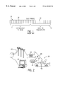
- FIG. 2 is a pictorial diagram of a wireless communication system for a motor vehicle according to the present invention.
- FIG. 3 is a block schematic diagram of a portion of the wireless communication system.
- a keyless motor vehicle control system 20 comprises a driver's remote control 21 , which preferably has the form of a key ring fob carried by a driver, and a control circuit 22 located in the motor vehicle 23 .
- the remote control 21 exchanges a radio frequency signals with the control circuit 22 , which responds by activating designated functions of the motor vehicle 23 .
- the control circuit 22 in the motor vehicle includes a microcomputer 24 with an internal microprocessor, memory in which the control program and data are stored, and input/output circuits.
- a standard clock circuit 26 supplies timing pulses to the microcomputer 24 .
- the service technician is able to place the microcomputer into different functional modes by operating a manual input switch 27 .
- a port of the microcomputer 24 may also be provided to connect a programming device, such as a keyboard or portable computer, for configuring the control circuit 22 .
- configuration of the control circuit 22 can be performed by downloading data via the radio frequency link.
- the control circuit 22 operates several functions on the motor vehicle, such as locking and unlocking the doors, unlatching the trunk lid, and starting the engine for example.
- the microcomputer 24 is interfaced to the corresponding actuating devices on the motor vehicle 23 .
- the control circuit 22 also may send commands via a parallel communication bus 36 to other control modules or computers in the motor vehicle 23 .
- microcomputer 24 has individual output lines 30 connected directly to the control devices for the respective functions being operated. Specifically, separate wires may be coupled to actuators which lock and unlock the doors, unlatch the trunk lid and start the engine.
- a serial output port 32 and a serial input port 34 of the microcomputer 24 are connected to a first radio frequency transceiver 35 which utilizes the Digital Enhanced Cordless Telecommunications (DECT) standard.
- the first radio frequency transceiver 35 modulates a standard RF frequency carrier with the serial digital data received from output port 32 and transmits that modulated radio frequency signal via an antenna 37 .
- the first transceiver 35 also receives and demodulates radio frequency signals received by the antenna 37 to recover serial digital data carried by that signal. The recovered data is sent to the microcomputer input port 34 .
- the first transceiver 35 of the control circuit 22 is designed to communicate with a second radio frequency transceiver 40 and antenna 42 both located within the remote control 21 .
- both transceivers 40 and 35 utilize the DECT protocol and are similar to devices found in cordless telephones.
- the second transceiver 40 has a receiver section which demodulates the received radio frequency signal to recover digital data carried by that signal and the recovered data is sent in a serial format to an input register 44 .
- the input register 44 converts the serial data stream from the second transceiver 40 into a parallel format which is read by a controller 46 .
- the controller 46 may be a hardwired device that sequentially performs the remote control procedure to be described or a programmable device which executes a software program to implement that procedure.
- the controller 46 of the remote control 12 is connected to an electrically erasable programmable read only memory (EEPROM) 48 which stores configuration and identification data for the remote control.
- EEPROM electrically erasable programmable read only memory
- a random access memory 49 also is provided to store information received from the motor vehicle, as will be described.
- a clock circuit 52 also provides timing signals for the controller 46 .
- a plurality of user operable switches 54 are connected to different input lines to the controller 46 in order for the driver to select the specific functions to be performed on the motor vehicle.
- a separate switch can be provided for the functions of unlocking and locking the doors, unlatching the trunk lid, and starting the engine.
- the remote control 21 also includes an encrypt or 50 connected to the controller 46 to encrypt a remote control security number for transmission to the control circuit 22 .
- the encrypt or 50 utilizes a secret-key cryptography algorithm to encrypt data for sending to the control circuit.
- the algorithm specifies a sequence of a plurality of logical operations which are performed on a known seed number and a challenge number received from the control circuit to produce a resultant number for transmission by the remote control.
- Several cryptography algorithms of this type are described by Mehrdad Foroozesh in an article entitled “Protecting Your Data With Cryptography,” UNIX Review, November 1996, volume 14, number 12, page 55(6), which description is incorporated herein by reference.
- Such encryption techniques and algorithms are commonly used to encode computer data being transmitted over common carriers. It should be understood that other encryption techniques may be used.
- Digital output data is sent by the controller 46 in parallel form to a parallel-in/serial-out output register 56 .
- the serial data from the output register 56 is applied to the input of a transmitter section in the second transceiver 40 which modulates a radio frequency signal which that data.
- the resultant RF signal is sent via the antenna 42 to the control circuit 22 in motor vehicle.
- the components of the remote control are powered by a battery.
- the corresponding switch 54 on the remote control 21 When the driver desires the vehicle to perform a given function the corresponding switch 54 on the remote control 21 is pressed. This sends a signal to the controller 46 which responds by obtaining a unique identification number assigned to this particular remote control and stored in the EEPROM 48 . The identification number and an indication of the switch 54 that was pressed are sent via output register 56 to the second transceiver 40 from which it is transmitted to the control circuit 22 in the adjacent motor vehicle 23 as seen in FIG. 2 .
- the remote control 21 before a message containing the identification number and switch indication may be sent, the remote control 21 must locate a pair of DECT frame time slots which are not already in use. This process begins by scanning each of the ten DECT frequencies. If the remote control 21 does not hear a message frame on a given frequency, it then forms a new message frame and selects an arbitrary pair of time slots to use. If a particular frequency already is carrying DECT messages, the remote control 21 listens during the message frames for an available pair of frame slots, that is ones which do not already contain message data. If none is found, the next DECT frequency is selected. When available time slots in each half of the message frame are found, the remote control 21 transmits the message in the time slot during the second half of the message frame. The remote control 21 then listens for an acknowledgment in the corresponding time slot during the first half of subsequent frames on the selected frequency.
- Receipt of a message frame causes the vehicle control circuit 22 , which had been in a “sleep state”, to wake-up wherein its microcomputer 24 to begin executing a software routine stored in memory.
- any of several well known data encryption algorithms may be employed to exchange data between the remote control 21 and the vehicle control circuit 22 for greater security and robustness against interference.
- the first portion of the communication process may be an exchange of messages according to encryption algorithm which verifies that the remote control is authentic, i.e. authorized to access this motor vehicle 23 .
- the first microcomputer 24 uses the switch indication received from the remote control 21 to determine the motor vehicle function to activate. For example, when the door unlock function is indicated, an unlock command signal is sent out over either communication bus 36 or one of the dedicated output lines 30 to a control circuit for door locks 58 of the motor vehicle 23 as seen in FIG. 2 . Other command signals unlatch the vehicle's trunk or start the engine.
- the control circuit in the motor vehicle 23 also may communicate via a cordless telephone base station 64 that is in the vicinity of the vehicle, typically within 300 meters.
- An RF communication link 65 using the DECT protocol is established between the cordless telephone base station and the motor vehicle control circuit 22 .
- the cordless telephone base station 64 is connected to a common carrier telephone network 66 through which dial-up communication paths may be established with devices connected to that network.
- cordless telephone base station 64 can dial a computer 62 which has been programed to diagnose the cause of malfunctions in motor vehicles.
- the computers 62 is similar to those commonly found in motor vehicle service facilities.
- This latter communication path is especially useful in transferring historical operating information from the vehicle to a computer system for diagnostic analysis. For example, if the motor vehicle 23 breaks down and can not be operated, the driver or a tow truck operator is able to send that operating information to a computer system at a repair facility for analysis. This enables sophisticated trouble shooting to be performed at a remote location and the problem fixed without taking the vehicle to the repair facility.
- a nearby cordless telephone base station 64 is employed to dial the repair facility and access the diagnostic computer 62 via the telephone network 66 .
- a cellular telephone with capability to communicate with DECT protocol devices can be used to transfer the historical operating information from the vehicle to the telephone network 66 and thus to diagnostic computer 62 .
- the person activates a switch 28 on the vehicle control circuit 22 .
- the microcomputer 24 responds to the switch activation by contacting the cordless telephone base station 64 using the DECT protocol similar to that described previously by which the remote control 21 contacted the control circuit 22 .
- the control circuit acts as the hand-held transceiver of the cordless telephone.
- the control circuit 22 searches the allocated frequencies for an available pair of time slots, such as 18 and 19 , to use and then transmits an access signal to the cordless telephone base station 64 .
- the cordless telephone base station 64 Upon receiving that access signal the cordless telephone base station 64 sends a reply to the vehicle control circuit 22 thereby establishing bidirectional communication link 65 in FIG. 2 .
- the control circuit sends the telephone number of the diagnostic computer 62 to the base station 64 , which responds by dialing that number into the telephone network 66 .
- the vehicle control circuit 22 notifies the diagnostic computer 62 of the desire to up-load operational information for analysis.
- the vehicle control circuit 22 transmits the information via RF link 65 to the cordless telephone base station 64 which in turn relays the data to the diagnostic computer 62 via the telephone network 66 .
- the remote control 21 can be employed to relay the historical operating data from the vehicle.
- the control circuit 22 upon failing to communicate with a cordless telephone base station 64 , the control circuit 22 establishes communication via RF link 43 with the remote control 21 using the DECT protocol as described previously. After that link 43 has been formed, the historical operating information is transmitted from the vehicle 23 to the remote control 21 which stores the data in its RAM 49 in FIG. 3 .
- the user then carries the remote control 21 to a location of a cordless telephone.
- a push-button switch on the remote control 21 is activated which results in contact being made with the base station 64 of the cordless telephone via RF link 68 using the DECT protocol previously described.
- the remote control instructs the base station to dial the telephone number of the diagnostic computer 62 .
- the vehicle operating data is transmitted from the remote control 21 to the diagnostic computer 62 .
- the remote control 21 can be taken to a service facility and the operating data is downloaded directly into the diagnostic computer 62 .
- the diagnostic computer 62 then analyzes the operational data in a similar manner as when the vehicle is in the repair facility and connected to the computer by cables.
- the results of the analysis can be transmitted via the same telecommunication links 66 and 65 to the vehicle 23 where the results are displayed to the driver or tow truck operator on a display connected to the control circuit via communication bus 36 in FIG. 2 .
- a technician at the repair facility can read the results from the screen of the diagnostic computer and communicate them to a person at the vehicle by a conventional telephone voice link using the base station 64 or a cellular telephone.
- the diagnostic computer 62 may formulate a correction command for curing the problem in the vehicle.
- the correction command then is transmitted via the same telecommunication links 66 and 65 to the vehicle 23 the control circuit implements the corrective action indicated by the command.
Abstract
Description
Claims (13)
Priority Applications (2)
| Application Number | Priority Date | Filing Date | Title |
|---|---|---|---|
| US09/354,366 US6169943B1 (en) | 1999-07-14 | 1999-07-14 | Motor vehicle diagnostic system using hand-held remote control |
| EP00114289A EP1069535A3 (en) | 1999-07-14 | 2000-07-04 | Motor vehicle diagnostic system using hand-held remote control |
Applications Claiming Priority (1)
| Application Number | Priority Date | Filing Date | Title |
|---|---|---|---|
| US09/354,366 US6169943B1 (en) | 1999-07-14 | 1999-07-14 | Motor vehicle diagnostic system using hand-held remote control |
Publications (1)
| Publication Number | Publication Date |
|---|---|
| US6169943B1 true US6169943B1 (en) | 2001-01-02 |
Family
ID=23393003
Family Applications (1)
| Application Number | Title | Priority Date | Filing Date |
|---|---|---|---|
| US09/354,366 Expired - Lifetime US6169943B1 (en) | 1999-07-14 | 1999-07-14 | Motor vehicle diagnostic system using hand-held remote control |
Country Status (2)
| Country | Link |
|---|---|
| US (1) | US6169943B1 (en) |
| EP (1) | EP1069535A3 (en) |
Cited By (125)
| Publication number | Priority date | Publication date | Assignee | Title |
|---|---|---|---|---|
| US6263265B1 (en) | 1999-10-01 | 2001-07-17 | General Electric Company | Web information vault |
| US6308120B1 (en) * | 2000-06-29 | 2001-10-23 | U-Haul International, Inc. | Vehicle service status tracking system and method |
| US6338152B1 (en) | 1999-10-28 | 2002-01-08 | General Electric Company | Method and system for remotely managing communication of data used for predicting malfunctions in a plurality of machines |
| US6360145B1 (en) * | 2000-05-16 | 2002-03-19 | General Motors Corporation | Vehicle platform-portable controller |
| US20020065698A1 (en) * | 1999-08-23 | 2002-05-30 | Schick Louis A. | System and method for managing a fleet of remote assets |
| US6401049B1 (en) * | 1996-09-04 | 2002-06-04 | Continental Teves Ag & Co., Ohg | Process for inspecting the components of a system in a motor vehicle |
| US6429773B1 (en) * | 2000-10-31 | 2002-08-06 | Hewlett-Packard Company | System for remotely communicating with a vehicle |
| US6489886B2 (en) * | 2000-04-19 | 2002-12-03 | Texas Instruments Deutschland, Gmbh | Security system to prevent unauthorized starting of the engine of a vehicle |
| US20020181405A1 (en) * | 2000-04-10 | 2002-12-05 | I/O Controls Corporation | System for providing remote access to diagnostic information over a wide area network |
| US6512974B2 (en) * | 2000-02-18 | 2003-01-28 | Optimum Power Technology | Engine management system |
| DE10138833A1 (en) * | 2001-08-14 | 2003-02-27 | Daimler Chrysler Ag | Device and method for remote diagnostics of vehicles |
| DE10145906A1 (en) * | 2001-09-18 | 2003-04-10 | Bosch Gmbh Robert | Method for carrying out remote diagnosis in a motor vehicle, vehicle diagnosis module and service center |
| US6606555B2 (en) * | 2000-12-22 | 2003-08-12 | Sony Corporation | Vehicle positioning apparatus, device, and method |
| US6615367B1 (en) | 1999-10-28 | 2003-09-02 | General Electric Company | Method and apparatus for diagnosing difficult to diagnose faults in a complex system |
| US6625589B1 (en) | 1999-10-28 | 2003-09-23 | General Electric Company | Method for adaptive threshold computation for time and frequency based anomalous feature identification in fault log data |
| US6654673B2 (en) | 2001-12-14 | 2003-11-25 | Caterpillar Inc | System and method for remotely monitoring the condition of machine |
| US6665606B2 (en) * | 2001-02-20 | 2003-12-16 | Cummins, Inc. | Distributed engine processing system |
| US20040015251A1 (en) * | 2000-12-01 | 2004-01-22 | Tsuyoshi Hamada | System for evaluating abnormal sound, sound recorder and apparatus for evaluating abnormal sound |
| US6745151B2 (en) | 2002-05-16 | 2004-06-01 | Ford Global Technologies, Llc | Remote diagnostics and prognostics methods for complex systems |
| US6757600B2 (en) * | 2001-02-21 | 2004-06-29 | J. Eberspacher Gmbh & Co. | Control device for a networkable device |
| US6757521B1 (en) | 2000-06-12 | 2004-06-29 | I/O Controls Corporation | Method and system for locating and assisting portable devices performing remote diagnostic analysis of a control network |
| US20040143417A1 (en) * | 1999-10-28 | 2004-07-22 | Hedlund Eric H. | Apparatus and method for performance and fault data analysis |
| US20040153362A1 (en) * | 1996-01-29 | 2004-08-05 | Progressive Casualty Insurance Company | Monitoring system for determining and communicating a cost of insurance |
| US6795935B1 (en) | 1999-10-28 | 2004-09-21 | General Electric Company | Diagnosis of faults in a complex system |
| US6807469B2 (en) * | 2001-06-15 | 2004-10-19 | Carcheckup, Llc | Auto diagnostic method and device |
| US20050004735A1 (en) * | 2003-07-02 | 2005-01-06 | Kelly Thomas J. | Systems and methods for providing proxy control functions in a work machine |
| US20050005167A1 (en) * | 2003-07-02 | 2005-01-06 | Kelly Thomas J. | Systems and methods for providing security operations in a work machine |
| US20050002354A1 (en) * | 2003-07-02 | 2005-01-06 | Kelly Thomas J. | Systems and methods for providing network communications between work machines |
| DE10329871A1 (en) * | 2003-07-02 | 2005-01-20 | Volkswagen Ag | Vehicle electronic unit telemetric diagnosis procedure sends fault data from vehicle process over mobile phone and internet link external diagnosis unit |
| US6847916B1 (en) * | 2000-06-12 | 2005-01-25 | I/O Controls Corporation | Method and system for monitoring, controlling, and locating portable devices performing remote diagnostic analysis of control network |
| US20050021860A1 (en) * | 2003-07-02 | 2005-01-27 | Kelly Thomas J. | Systems and methods for providing server operations in a work machine |
| US20050102584A1 (en) * | 2003-11-06 | 2005-05-12 | Ramesh Paturi | Method, system, and storage medium for communicating with vehicle control |
| US20050124234A1 (en) * | 2003-12-05 | 2005-06-09 | Robin Sells | Remote marine craft system and methods of using same |
| US20050147490A1 (en) * | 2004-01-05 | 2005-07-07 | Richard Soucy | System and method for controlling the speed of a gas turbine engine |
| US20050171661A1 (en) * | 1999-10-28 | 2005-08-04 | Aiman Abdel-Malek | Diagnosis and repair system and method |
| US20060041349A1 (en) * | 2004-08-19 | 2006-02-23 | Spx Corporation | Vehicle diagnostic device |
| WO2006081367A2 (en) * | 2005-01-25 | 2006-08-03 | Donald Packham | Wireless remote control apparatus and method |
| US20060217065A1 (en) * | 2005-03-23 | 2006-09-28 | Skipjam Corp. | Radio frequency remote control apparatus and methodology |
| US20060293813A1 (en) * | 2004-12-04 | 2006-12-28 | Seong Taeg Nou | System and method for controlling remote vehicle using telematics system |
| US20070005201A1 (en) * | 2005-06-30 | 2007-01-04 | Chenn Ieon C | Cellphone based vehicle diagnostic system |
| US20070239322A1 (en) * | 2006-04-05 | 2007-10-11 | Zonar Comliance Systems, Llc | Generating a numerical ranking of driver performance based on a plurality of metrics |
| US20070294031A1 (en) * | 2006-06-20 | 2007-12-20 | Zonar Compliance Systems, Llc | Method and apparatus to utilize gps data to replace route planning software |
| US20070298929A1 (en) * | 2006-06-27 | 2007-12-27 | Beth Klimek | Automated mechanical transmission having wireless interface |
| WO2008000603A1 (en) | 2006-06-29 | 2008-01-03 | Zf Friedrichshafen Ag | Monitoring and administration of components |
| US20080167773A1 (en) * | 2005-06-14 | 2008-07-10 | Bayerische Motoren Werke Aktiengesellschaft | Method and System of Communication Between a Motor Vehicle and a Diagnostic Unit |
| US20080174448A1 (en) * | 2006-10-31 | 2008-07-24 | Edison Hudson | Modular Controller |
| US20080208405A1 (en) * | 2007-02-23 | 2008-08-28 | Gm Global Technology Operations, Inc. | Method and system for facilitating communication of information to a mobile platform |
| US20080290998A1 (en) * | 2005-04-29 | 2008-11-27 | Nick Ramirez | Remote Ignition, Theft Deterrence, and Records Keeping System for a Vehicle |
| US20080291014A1 (en) * | 2007-05-23 | 2008-11-27 | Toyota Engineering & Manufacturing North America, Inc. | System and method for remote diagnosis and repair of a plant malfunction with software agents |
| US20080316007A1 (en) * | 2001-09-11 | 2008-12-25 | Zonar Systems, Inc. | System and process to ensure performance of mandated inspections |
| US7532640B2 (en) | 2003-07-02 | 2009-05-12 | Caterpillar Inc. | Systems and methods for performing protocol conversions in a machine |
| US7577581B1 (en) | 2000-10-31 | 2009-08-18 | Hewlett-Packard Development Company, L.P. | Method for targeting promotions to individual associated with a vehicle |
| US20090237245A1 (en) * | 2001-09-11 | 2009-09-24 | Zonar Systems, Inc. | Method and apparatus to automate data collection during a mandatory inpsection |
| US20090248362A1 (en) * | 2001-09-11 | 2009-10-01 | Zonar Systems, Inc. | System and process to ensure performance of mandated safety and maintenance inspections |
| US7673034B1 (en) * | 2000-05-05 | 2010-03-02 | 3Com Corporation | Self service data interface |
| US20100185638A1 (en) * | 2009-01-15 | 2010-07-22 | Honeywell International Inc. | Image Search Enhanced Vehicle Telemaintenance |
| US20100185479A1 (en) * | 2006-06-20 | 2010-07-22 | Zonar Systems, Inc. | Method and apparatus to analyze gps data to determine if a vehicle has adhered to a predetermined route |
| US20100218214A1 (en) * | 2009-02-26 | 2010-08-26 | At&T Intellectual Property I, L.P. | Intelligent remote control |
| US20100256864A1 (en) * | 2000-06-12 | 2010-10-07 | I/O Controls Corporation | System and method for facilitating diagnosis and maintenance of a mobile conveyance |
| US20110004348A1 (en) * | 2008-03-13 | 2011-01-06 | Zf Friedrichshafen Ag | Arrangement for transmitting data and/or signals in a transmission |
| US20110074562A1 (en) * | 2005-04-29 | 2011-03-31 | Bulletproof Electronics, Inc. | Remote Ignition, Theft Deterrence, and Records Keeping System for a Vehicle |
| US20110137490A1 (en) * | 2009-12-03 | 2011-06-09 | Continental Automotive Gmbh | Mobile interface and system for controlling vehicle functions |
| US20110225096A1 (en) * | 2010-03-15 | 2011-09-15 | Hanbum Cho | Method And System For Providing Diagnostic Feedback Based On Diagnostic Data |
| US8140358B1 (en) | 1996-01-29 | 2012-03-20 | Progressive Casualty Insurance Company | Vehicle monitoring system |
| CN101617546B (en) * | 2007-02-23 | 2012-10-10 | 通用汽车环球科技运作公司 | Method and system for selectively communicating with mobile platforms |
| CN101582199B (en) * | 2009-06-12 | 2012-10-17 | 深圳创维-Rgb电子有限公司 | Wireless remote control television system |
| US8340855B2 (en) | 2008-04-22 | 2012-12-25 | Spx Corporation | USB isolation for vehicle communication interface |
| US8463953B2 (en) | 2010-08-18 | 2013-06-11 | Snap-On Incorporated | System and method for integrating devices for servicing a device-under-service |
| US8477020B2 (en) | 2005-04-29 | 2013-07-02 | Heistproof, Llc | Remote ignition, theft detterence, and records keeping system for a vehicle |
| US20130237192A1 (en) * | 2010-12-09 | 2013-09-12 | Lg Electronics Inc. | Access method between a terminal and a base station in a wireless communication system and apparatus thereof |
| US8560168B2 (en) | 2010-08-18 | 2013-10-15 | Snap-On Incorporated | System and method for extending communication range and reducing power consumption of vehicle diagnostic equipment |
| US8736419B2 (en) | 2010-12-02 | 2014-05-27 | Zonar Systems | Method and apparatus for implementing a vehicle inspection waiver program |
| US8747148B2 (en) | 2010-08-03 | 2014-06-10 | Bosch Automotive Service Solutions Llc | Diagnostic tool with recessed connector |
| US8754779B2 (en) | 2010-08-18 | 2014-06-17 | Snap-On Incorporated | System and method for displaying input data on a remote display device |
| US8810385B2 (en) | 2001-09-11 | 2014-08-19 | Zonar Systems, Inc. | System and method to improve the efficiency of vehicle inspections by enabling remote actuation of vehicle components |
| US8831814B2 (en) | 2012-04-27 | 2014-09-09 | Innova Electronics, Inc. | Electronic device with virtual display and input |
| US8909416B2 (en) | 2008-04-14 | 2014-12-09 | Innova Electronics, Inc. | Handheld scan tool with fixed solution capability |
| US8983785B2 (en) | 2010-08-18 | 2015-03-17 | Snap-On Incorporated | System and method for simultaneous display of waveforms generated from input signals received at a data acquisition device |
| US9014908B2 (en) | 2013-01-04 | 2015-04-21 | Innova Electronics, Inc. | Multi-stage diagnostic system and method |
| US9117321B2 (en) | 2010-08-18 | 2015-08-25 | Snap-On Incorporated | Method and apparatus to use remote and local control modes to acquire and visually present data |
| US9141503B1 (en) | 2014-09-30 | 2015-09-22 | Innova Electronics, Inc. | Vehicle-specific diagnostic reset device and method |
| US9142066B2 (en) | 2013-01-04 | 2015-09-22 | Innova Electronics, Inc. | Multi-stage diagnostic system and method |
| US9230437B2 (en) | 2006-06-20 | 2016-01-05 | Zonar Systems, Inc. | Method and apparatus to encode fuel use data with GPS data and to analyze such data |
| US9324194B2 (en) | 2013-06-11 | 2016-04-26 | Innova Electronics, Inc. | Method and system for database compilation on a remote electronic device |
| US9330507B2 (en) | 2010-08-18 | 2016-05-03 | Snap-On Incorporated | System and method for selecting individual parameters to transition from text-to-graph or graph-to-text |
| US9342934B2 (en) | 2014-09-30 | 2016-05-17 | Innova Electronics, Inc. | Vehicle specific reset device and method |
| US9373201B2 (en) | 2012-05-23 | 2016-06-21 | Enterprise Holdings, Inc. | Rental/car-share vehicle access and management system and method |
| US9384599B2 (en) | 2005-06-30 | 2016-07-05 | Innova Electronics, Inc. | Handheld automotive diagnostic tool with VIN decoder and communication system |
| US9384111B2 (en) | 2011-12-23 | 2016-07-05 | Zonar Systems, Inc. | Method and apparatus for GPS based slope determination, real-time vehicle mass determination, and vehicle efficiency analysis |
| US9412282B2 (en) | 2011-12-24 | 2016-08-09 | Zonar Systems, Inc. | Using social networking to improve driver performance based on industry sharing of driver performance data |
| US9483884B2 (en) | 2012-05-09 | 2016-11-01 | Innova Electronics, Inc. | Smart phone app-based remote vehicle diagnostic system and method |
| US9494125B2 (en) | 2014-06-13 | 2016-11-15 | Innova Electronics, Inc. | System and method of ignition coil testing |
| US9499128B2 (en) | 2013-03-14 | 2016-11-22 | The Crawford Group, Inc. | Mobile device-enhanced user selection of specific rental vehicles for a rental vehicle reservation |
| US9527515B2 (en) | 2011-12-23 | 2016-12-27 | Zonar Systems, Inc. | Vehicle performance based on analysis of drive data |
| EP3109812A1 (en) | 2015-06-22 | 2016-12-28 | Mohamid Arbib | Method for automatically generating, documenting and distributing vehicle data |
| US9563869B2 (en) | 2010-09-14 | 2017-02-07 | Zonar Systems, Inc. | Automatic incorporation of vehicle data into documents captured at a vehicle using a mobile computing device |
| US9633492B2 (en) | 2010-08-18 | 2017-04-25 | Snap-On Incorporated | System and method for a vehicle scanner to automatically execute a test suite from a storage card |
| US9646432B2 (en) | 2008-04-14 | 2017-05-09 | Innova Electronics Corporation | Hand held data retrieval device with fixed solution capability |
| US9646427B2 (en) | 2014-10-08 | 2017-05-09 | Innova Electronics Corporation | System for detecting the operational status of a vehicle using a handheld communication device |
| US9761066B2 (en) | 2013-12-04 | 2017-09-12 | Innova Electronics Corporation | System and method for monitoring the status of a vehicle battery system |
| US9761062B2 (en) | 2010-03-10 | 2017-09-12 | Innova Electronics Corporation | Method and apparatus for indicating an automotive diagnostic urgency |
| US9769359B2 (en) | 2013-12-16 | 2017-09-19 | Innova Electronics Corporation | Flexible camera device |
| US9824507B2 (en) | 2005-06-30 | 2017-11-21 | Innova Electronics Corporation | Mobile device based vehicle diagnostic system |
| USD804339S1 (en) | 2016-08-08 | 2017-12-05 | Innova Electronics Corporation | Scan tool |
| USD804338S1 (en) | 2016-08-08 | 2017-12-05 | Innova Electronics Corporation | Scan tool |
| US9858462B2 (en) | 2006-06-20 | 2018-01-02 | Zonar Systems, Inc. | Method and system for making deliveries of a fluid to a set of tanks |
| USD806592S1 (en) | 2016-08-08 | 2018-01-02 | Innova Electronics, Inc. | Scan tool |
| USD806593S1 (en) | 2016-08-08 | 2018-01-02 | Innova Electronics, Inc. | Scan tool |
| US9892568B2 (en) | 2012-08-20 | 2018-02-13 | Innova Electronics Corporation | Method and system for determining the likely operating cost for a particular type of vehicle over a defined period |
| US10056008B1 (en) | 2006-06-20 | 2018-08-21 | Zonar Systems, Inc. | Using telematics data including position data and vehicle analytics to train drivers to improve efficiency of vehicle use |
| US10163281B2 (en) | 2017-01-12 | 2018-12-25 | Innova Electronics Corporation | Adaptive vehicle monitoring system |
| US10185455B2 (en) * | 2012-10-04 | 2019-01-22 | Zonar Systems, Inc. | Mobile computing device for fleet telematics |
| US10289651B2 (en) | 2012-04-01 | 2019-05-14 | Zonar Systems, Inc. | Method and apparatus for matching vehicle ECU programming to current vehicle operating conditions |
| US10417929B2 (en) | 2012-10-04 | 2019-09-17 | Zonar Systems, Inc. | Virtual trainer for in vehicle driver coaching and to collect metrics to improve driver performance |
| US10431097B2 (en) | 2011-06-13 | 2019-10-01 | Zonar Systems, Inc. | System and method to enhance the utility of vehicle inspection records by including route identification data in each vehicle inspection record |
| US10431020B2 (en) | 2010-12-02 | 2019-10-01 | Zonar Systems, Inc. | Method and apparatus for implementing a vehicle inspection waiver program |
| US10462225B2 (en) | 2017-08-25 | 2019-10-29 | Innova Electronics Corporation | Method and system for autonomously interfacing a vehicle electrical system of a legacy vehicle to an intelligent transportation system and vehicle diagnostic resources |
| US10515489B2 (en) | 2012-05-23 | 2019-12-24 | Enterprise Holdings, Inc. | Rental/car-share vehicle access and management system and method |
| US10600096B2 (en) | 2010-11-30 | 2020-03-24 | Zonar Systems, Inc. | System and method for obtaining competitive pricing for vehicle services |
| US10640060B2 (en) | 2016-03-17 | 2020-05-05 | Innova Electronics Corporation | Vehicle repair shop pre-inspection and post-inspection verification system |
| US10643403B2 (en) | 2012-08-20 | 2020-05-05 | Innova Electronics Corporation | Predictive diagnostic method and system |
| US10665040B2 (en) | 2010-08-27 | 2020-05-26 | Zonar Systems, Inc. | Method and apparatus for remote vehicle diagnosis |
| US10706647B2 (en) | 2010-12-02 | 2020-07-07 | Zonar Systems, Inc. | Method and apparatus for implementing a vehicle inspection waiver program |
| US11030702B1 (en) | 2012-02-02 | 2021-06-08 | Progressive Casualty Insurance Company | Mobile insurance platform system |
| US11341853B2 (en) | 2001-09-11 | 2022-05-24 | Zonar Systems, Inc. | System and method to enhance the utility of vehicle inspection records by including route identification data in each vehicle inspection record |
Families Citing this family (7)
| Publication number | Priority date | Publication date | Assignee | Title |
|---|---|---|---|---|
| JP2003122426A (en) * | 2001-10-16 | 2003-04-25 | Keihin Corp | Remote maintenance system |
| DE10210362A1 (en) * | 2002-03-08 | 2003-09-18 | Opel Adam Ag | Diagnostic system for a motor vehicle |
| DE10328674A1 (en) * | 2003-06-26 | 2005-01-13 | Daimlerchrysler Ag | System for internet-based connection of a vehicle to a base station |
| US20060061483A1 (en) * | 2004-09-17 | 2006-03-23 | Smith Timothy D | Monitoring and security system and method |
| DE102005038712A1 (en) * | 2005-08-15 | 2007-03-15 | Johnson Controls Gmbh | Circuit arrangement for a radio transmitter with only one oscillator and method for clock supply of a transmitting unit |
| DE102006042312B4 (en) * | 2006-09-06 | 2010-04-08 | Audi Ag | Reading vehicle data |
| DE102013003928A1 (en) * | 2013-03-08 | 2014-09-11 | Deutsche Telekom Ag | Vehicle authorization device, in particular vehicle key, system and method for supporting the maintenance and / or repair of a vehicle, computer program and computer program product |
Citations (17)
| Publication number | Priority date | Publication date | Assignee | Title |
|---|---|---|---|---|
| US4853850A (en) * | 1985-09-10 | 1989-08-01 | Krass Jr James E | Vehicle computer diagnostic interface apparatus |
| US5003476A (en) * | 1988-09-07 | 1991-03-26 | Fuji Jukogyo Kabushiki Kaisha | Diagnostic system for a motor vehicle |
| US5003477A (en) * | 1988-02-18 | 1991-03-26 | Fuji Jukogyo Kabushiki Kaisha | Diagnosis system for a motor vehicle |
| US5050080A (en) * | 1988-09-28 | 1991-09-17 | Fuji Jukogyo Kabushiki Kaisha | Diagnostic system for a motor vehicle |
| US5214582A (en) * | 1991-01-30 | 1993-05-25 | Edge Diagnostic Systems | Interactive diagnostic system for an automotive vehicle, and method |
| US5227766A (en) * | 1990-03-13 | 1993-07-13 | Oki Electric Industry Co., Ltd. | Abnormality detecting system |
| US5276619A (en) * | 1990-04-06 | 1994-01-04 | Nippondenso Co., Ltd. | Electronic control system with self-diagnostic function for use in motor vehicle |
| US5479347A (en) * | 1993-06-17 | 1995-12-26 | Nippondenso Co., Ltd. | Vehicle diagnosis system |
| US5506773A (en) * | 1992-08-11 | 1996-04-09 | Nippondenso Co., Ltd. | Self-diagnosing apparatus for motor vehicles |
| US5541840A (en) * | 1993-06-25 | 1996-07-30 | Chrysler Corporation | Hand held automotive diagnostic service tool |
| US5555498A (en) * | 1994-03-18 | 1996-09-10 | Chrysler Corporation | Circuit and method for interfacing vehicle controller and diagnostic test instrument |
| US5565856A (en) * | 1993-10-05 | 1996-10-15 | Nippondenso Co., Ltd. | Abnormality detecting device for vehicle communication system and method of using same |
| US5590040A (en) * | 1992-08-19 | 1996-12-31 | Nippondenso Co., Ltd. | Self-diagnosis apparatus for vehicle |
| US5646865A (en) * | 1994-10-27 | 1997-07-08 | General Motors Corporation | Automotive diagnostic communications |
| US5696676A (en) * | 1993-02-18 | 1997-12-09 | Nippondenso Co., Ltd. | Self-diagnosis apparatus for vehicles |
| US5884202A (en) * | 1995-07-20 | 1999-03-16 | Hewlett-Packard Company | Modular wireless diagnostic test and information system |
| US5987394A (en) * | 1997-03-31 | 1999-11-16 | Honda Giken Kogyo Kabushiki Kaisha | Apparatus for preparing vehicle diagnosing program |
Family Cites Families (8)
| Publication number | Priority date | Publication date | Assignee | Title |
|---|---|---|---|---|
| US4602127A (en) * | 1984-03-09 | 1986-07-22 | Micro Processor Systems, Inc. | Diagnostic data recorder |
| GB2263376A (en) * | 1992-01-02 | 1993-07-21 | Leslie Keith Davies | Vehicle monitoring equipment |
| US5442553A (en) * | 1992-11-16 | 1995-08-15 | Motorola | Wireless motor vehicle diagnostic and software upgrade system |
| GB2288892A (en) * | 1994-04-29 | 1995-11-01 | Oakrange Engineering Ltd | Vehicle fleet monitoring apparatus |
| GB2290631B (en) * | 1994-06-24 | 1998-11-11 | Fuji Heavy Ind Ltd | Diagnosis system for motor vehicle and the method thereof |
| DE4446512A1 (en) * | 1994-12-24 | 1996-06-27 | Sel Alcatel Ag | Device for carrying out a vehicle test or for evaluating vehicle errors |
| DE19531415C2 (en) * | 1995-08-26 | 1999-11-25 | Mannesmann Vdo Ag | Device for the input, transmission and storage of information for a motor vehicle |
| DE19732900A1 (en) * | 1997-07-30 | 1999-02-04 | Bayerische Motoren Werke Ag | Vehicle with a memory for retrievable diagnostic data and with a remote-controlled central locking system |
-
1999
- 1999-07-14 US US09/354,366 patent/US6169943B1/en not_active Expired - Lifetime
-
2000
- 2000-07-04 EP EP00114289A patent/EP1069535A3/en not_active Withdrawn
Patent Citations (18)
| Publication number | Priority date | Publication date | Assignee | Title |
|---|---|---|---|---|
| US4853850A (en) * | 1985-09-10 | 1989-08-01 | Krass Jr James E | Vehicle computer diagnostic interface apparatus |
| US5003477A (en) * | 1988-02-18 | 1991-03-26 | Fuji Jukogyo Kabushiki Kaisha | Diagnosis system for a motor vehicle |
| US5003476A (en) * | 1988-09-07 | 1991-03-26 | Fuji Jukogyo Kabushiki Kaisha | Diagnostic system for a motor vehicle |
| US5050080A (en) * | 1988-09-28 | 1991-09-17 | Fuji Jukogyo Kabushiki Kaisha | Diagnostic system for a motor vehicle |
| US5227766A (en) * | 1990-03-13 | 1993-07-13 | Oki Electric Industry Co., Ltd. | Abnormality detecting system |
| US5276619A (en) * | 1990-04-06 | 1994-01-04 | Nippondenso Co., Ltd. | Electronic control system with self-diagnostic function for use in motor vehicle |
| US5214582A (en) * | 1991-01-30 | 1993-05-25 | Edge Diagnostic Systems | Interactive diagnostic system for an automotive vehicle, and method |
| US5214582C1 (en) * | 1991-01-30 | 2001-06-26 | Edge Diagnostic Systems | Interactive diagnostic system for an automobile vehicle and method |
| US5506773A (en) * | 1992-08-11 | 1996-04-09 | Nippondenso Co., Ltd. | Self-diagnosing apparatus for motor vehicles |
| US5590040A (en) * | 1992-08-19 | 1996-12-31 | Nippondenso Co., Ltd. | Self-diagnosis apparatus for vehicle |
| US5696676A (en) * | 1993-02-18 | 1997-12-09 | Nippondenso Co., Ltd. | Self-diagnosis apparatus for vehicles |
| US5479347A (en) * | 1993-06-17 | 1995-12-26 | Nippondenso Co., Ltd. | Vehicle diagnosis system |
| US5541840A (en) * | 1993-06-25 | 1996-07-30 | Chrysler Corporation | Hand held automotive diagnostic service tool |
| US5565856A (en) * | 1993-10-05 | 1996-10-15 | Nippondenso Co., Ltd. | Abnormality detecting device for vehicle communication system and method of using same |
| US5555498A (en) * | 1994-03-18 | 1996-09-10 | Chrysler Corporation | Circuit and method for interfacing vehicle controller and diagnostic test instrument |
| US5646865A (en) * | 1994-10-27 | 1997-07-08 | General Motors Corporation | Automotive diagnostic communications |
| US5884202A (en) * | 1995-07-20 | 1999-03-16 | Hewlett-Packard Company | Modular wireless diagnostic test and information system |
| US5987394A (en) * | 1997-03-31 | 1999-11-16 | Honda Giken Kogyo Kabushiki Kaisha | Apparatus for preparing vehicle diagnosing program |
Cited By (207)
| Publication number | Priority date | Publication date | Assignee | Title |
|---|---|---|---|---|
| US9754424B2 (en) | 1996-01-29 | 2017-09-05 | Progressive Casualty Insurance Company | Vehicle monitoring system |
| US8090598B2 (en) | 1996-01-29 | 2012-01-03 | Progressive Casualty Insurance Company | Monitoring system for determining and communicating a cost of insurance |
| US20040153362A1 (en) * | 1996-01-29 | 2004-08-05 | Progressive Casualty Insurance Company | Monitoring system for determining and communicating a cost of insurance |
| US8140358B1 (en) | 1996-01-29 | 2012-03-20 | Progressive Casualty Insurance Company | Vehicle monitoring system |
| US8311858B2 (en) | 1996-01-29 | 2012-11-13 | Progressive Casualty Insurance Company | Vehicle monitoring system |
| US8595034B2 (en) | 1996-01-29 | 2013-11-26 | Progressive Casualty Insurance Company | Monitoring system for determining and communicating a cost of insurance |
| US8892451B2 (en) | 1996-01-29 | 2014-11-18 | Progressive Casualty Insurance Company | Vehicle monitoring system |
| US6401049B1 (en) * | 1996-09-04 | 2002-06-04 | Continental Teves Ag & Co., Ohg | Process for inspecting the components of a system in a motor vehicle |
| US20020065698A1 (en) * | 1999-08-23 | 2002-05-30 | Schick Louis A. | System and method for managing a fleet of remote assets |
| US6263265B1 (en) | 1999-10-01 | 2001-07-17 | General Electric Company | Web information vault |
| US6615367B1 (en) | 1999-10-28 | 2003-09-02 | General Electric Company | Method and apparatus for diagnosing difficult to diagnose faults in a complex system |
| US7209817B2 (en) | 1999-10-28 | 2007-04-24 | General Electric Company | Diagnosis and repair system and method |
| US7100084B2 (en) | 1999-10-28 | 2006-08-29 | General Electric Company | Method and apparatus for diagnosing difficult to diagnose faults in a complex system |
| US7013239B2 (en) | 1999-10-28 | 2006-03-14 | General Electric Company | Apparatus and method for performance and fault data analysis |
| US20040143417A1 (en) * | 1999-10-28 | 2004-07-22 | Hedlund Eric H. | Apparatus and method for performance and fault data analysis |
| US6625589B1 (en) | 1999-10-28 | 2003-09-23 | General Electric Company | Method for adaptive threshold computation for time and frequency based anomalous feature identification in fault log data |
| US6959235B1 (en) | 1999-10-28 | 2005-10-25 | General Electric Company | Diagnosis and repair system and method |
| US20050171661A1 (en) * | 1999-10-28 | 2005-08-04 | Aiman Abdel-Malek | Diagnosis and repair system and method |
| US6795935B1 (en) | 1999-10-28 | 2004-09-21 | General Electric Company | Diagnosis of faults in a complex system |
| US20040073844A1 (en) * | 1999-10-28 | 2004-04-15 | Unkle C. Richard | Method and apparatus for diagnosing difficult diagnose faults in a complex system |
| US6338152B1 (en) | 1999-10-28 | 2002-01-08 | General Electric Company | Method and system for remotely managing communication of data used for predicting malfunctions in a plurality of machines |
| US6512974B2 (en) * | 2000-02-18 | 2003-01-28 | Optimum Power Technology | Engine management system |
| US8442514B2 (en) | 2000-04-10 | 2013-05-14 | I/O Controls Corporation | System and method for facilitating diagnosis and maintenance of a mobile conveyance |
| US20050283285A1 (en) * | 2000-04-10 | 2005-12-22 | I/O Controls Corporation | Method and system for monitoring, controlling, and locating portable devices performing remote diagnostic analysis of control network |
| US20100235042A1 (en) * | 2000-04-10 | 2010-09-16 | I/O Controls Corporation | System and method for facilitating diagnosis and maintenance of a mobile conveyance |
| US7398083B2 (en) | 2000-04-10 | 2008-07-08 | I/O Controls Corporation | Method and system for monitoring, controlling, and locating portable devices performing remote diagnostic analysis of control network |
| US20020181405A1 (en) * | 2000-04-10 | 2002-12-05 | I/O Controls Corporation | System for providing remote access to diagnostic information over a wide area network |
| US7734287B2 (en) * | 2000-04-10 | 2010-06-08 | I/O Controls Corporation | System for providing remote access to diagnostic information over a wide area network |
| US9183680B2 (en) | 2000-04-10 | 2015-11-10 | I/O Controls Corporation | System and method for facilitating diagnosis and maintenance of a mobile conveyance |
| US6489886B2 (en) * | 2000-04-19 | 2002-12-03 | Texas Instruments Deutschland, Gmbh | Security system to prevent unauthorized starting of the engine of a vehicle |
| US7673034B1 (en) * | 2000-05-05 | 2010-03-02 | 3Com Corporation | Self service data interface |
| US6360145B1 (en) * | 2000-05-16 | 2002-03-19 | General Motors Corporation | Vehicle platform-portable controller |
| US20100256865A1 (en) * | 2000-06-12 | 2010-10-07 | I/O Controls Corporation | System and method for facilitating diagnosis and maintenance of a mobile conveyance |
| US6847916B1 (en) * | 2000-06-12 | 2005-01-25 | I/O Controls Corporation | Method and system for monitoring, controlling, and locating portable devices performing remote diagnostic analysis of control network |
| US8116759B2 (en) | 2000-06-12 | 2012-02-14 | I/O Controls Corporation | System and method for facilitating diagnosis and maintenance of a mobile conveyance |
| US6757521B1 (en) | 2000-06-12 | 2004-06-29 | I/O Controls Corporation | Method and system for locating and assisting portable devices performing remote diagnostic analysis of a control network |
| US20100256864A1 (en) * | 2000-06-12 | 2010-10-07 | I/O Controls Corporation | System and method for facilitating diagnosis and maintenance of a mobile conveyance |
| US8472942B2 (en) | 2000-06-12 | 2013-06-25 | I/O Controls Corporation | System and method for facilitating diagnosis and maintenance of a mobile conveyance |
| US6477452B2 (en) | 2000-06-29 | 2002-11-05 | U-Haul International, Inc. | Vehicle service status tracking system and method |
| US6308120B1 (en) * | 2000-06-29 | 2001-10-23 | U-Haul International, Inc. | Vehicle service status tracking system and method |
| US6429773B1 (en) * | 2000-10-31 | 2002-08-06 | Hewlett-Packard Company | System for remotely communicating with a vehicle |
| US7577581B1 (en) | 2000-10-31 | 2009-08-18 | Hewlett-Packard Development Company, L.P. | Method for targeting promotions to individual associated with a vehicle |
| US7187773B2 (en) * | 2000-12-01 | 2007-03-06 | Daihatsu Motor Co., Ltd. | System for evaluating abnormal sound, sound recorder and apparatus for evaluating abnormal sound |
| US20040015251A1 (en) * | 2000-12-01 | 2004-01-22 | Tsuyoshi Hamada | System for evaluating abnormal sound, sound recorder and apparatus for evaluating abnormal sound |
| US6606555B2 (en) * | 2000-12-22 | 2003-08-12 | Sony Corporation | Vehicle positioning apparatus, device, and method |
| US6665606B2 (en) * | 2001-02-20 | 2003-12-16 | Cummins, Inc. | Distributed engine processing system |
| US6757600B2 (en) * | 2001-02-21 | 2004-06-29 | J. Eberspacher Gmbh & Co. | Control device for a networkable device |
| US6925368B2 (en) * | 2001-06-15 | 2005-08-02 | Carcheckup, Llc | Auto diagnostic method and device |
| US6807469B2 (en) * | 2001-06-15 | 2004-10-19 | Carcheckup, Llc | Auto diagnostic method and device |
| US20050043869A1 (en) * | 2001-06-15 | 2005-02-24 | Carcheckup, Llc. (An Indiana Limited Liability Company) | Auto diagnostic method and device |
| DE10138833A1 (en) * | 2001-08-14 | 2003-02-27 | Daimler Chrysler Ag | Device and method for remote diagnostics of vehicles |
| US6553292B2 (en) | 2001-08-14 | 2003-04-22 | Daimlerchrysler Ag | Device and method for performing remote diagnostics on vehicles |
| US8106757B2 (en) | 2001-09-11 | 2012-01-31 | Zonar Systems, Inc. | System and process to validate inspection data |
| US20080316007A1 (en) * | 2001-09-11 | 2008-12-25 | Zonar Systems, Inc. | System and process to ensure performance of mandated inspections |
| US11341853B2 (en) | 2001-09-11 | 2022-05-24 | Zonar Systems, Inc. | System and method to enhance the utility of vehicle inspection records by including route identification data in each vehicle inspection record |
| US7808369B2 (en) | 2001-09-11 | 2010-10-05 | Zonar Systems, Inc. | System and process to ensure performance of mandated inspections |
| US20090237245A1 (en) * | 2001-09-11 | 2009-09-24 | Zonar Systems, Inc. | Method and apparatus to automate data collection during a mandatory inpsection |
| US8810385B2 (en) | 2001-09-11 | 2014-08-19 | Zonar Systems, Inc. | System and method to improve the efficiency of vehicle inspections by enabling remote actuation of vehicle components |
| US20090248362A1 (en) * | 2001-09-11 | 2009-10-01 | Zonar Systems, Inc. | System and process to ensure performance of mandated safety and maintenance inspections |
| US20090256693A1 (en) * | 2001-09-11 | 2009-10-15 | Zonar Systems, Inc. | System and process to validate inspection data |
| US7944345B2 (en) | 2001-09-11 | 2011-05-17 | Zonar Systems, Inc. | System and process to ensure performance of mandated safety and maintenance inspections |
| US8400296B2 (en) | 2001-09-11 | 2013-03-19 | Zonar Systems, Inc. | Method and apparatus to automate data collection during a mandatory inspection |
| DE10145906A1 (en) * | 2001-09-18 | 2003-04-10 | Bosch Gmbh Robert | Method for carrying out remote diagnosis in a motor vehicle, vehicle diagnosis module and service center |
| US7096101B2 (en) | 2001-09-18 | 2006-08-22 | Robert Bosch Gmbh | Method for carrying out a telediagnosis on a motor vehicle, vehicle diagnosis module and service center |
| US20040112124A1 (en) * | 2001-09-18 | 2004-06-17 | Thomas Sonnenrein | Method for carrying out a telediagnosis on a motor vehicle, vehicle diagnosis module and service center |
| US6654673B2 (en) | 2001-12-14 | 2003-11-25 | Caterpillar Inc | System and method for remotely monitoring the condition of machine |
| US6745151B2 (en) | 2002-05-16 | 2004-06-01 | Ford Global Technologies, Llc | Remote diagnostics and prognostics methods for complex systems |
| US20050005167A1 (en) * | 2003-07-02 | 2005-01-06 | Kelly Thomas J. | Systems and methods for providing security operations in a work machine |
| DE10329871B4 (en) * | 2003-07-02 | 2017-12-28 | Volkswagen Ag | Method and system for the telemetric diagnosis of electronic equipment of a vehicle |
| US7532640B2 (en) | 2003-07-02 | 2009-05-12 | Caterpillar Inc. | Systems and methods for performing protocol conversions in a machine |
| US20050002354A1 (en) * | 2003-07-02 | 2005-01-06 | Kelly Thomas J. | Systems and methods for providing network communications between work machines |
| DE10329871A1 (en) * | 2003-07-02 | 2005-01-20 | Volkswagen Ag | Vehicle electronic unit telemetric diagnosis procedure sends fault data from vehicle process over mobile phone and internet link external diagnosis unit |
| US20050021860A1 (en) * | 2003-07-02 | 2005-01-27 | Kelly Thomas J. | Systems and methods for providing server operations in a work machine |
| US7983820B2 (en) | 2003-07-02 | 2011-07-19 | Caterpillar Inc. | Systems and methods for providing proxy control functions in a work machine |
| US7516244B2 (en) | 2003-07-02 | 2009-04-07 | Caterpillar Inc. | Systems and methods for providing server operations in a work machine |
| US20050004735A1 (en) * | 2003-07-02 | 2005-01-06 | Kelly Thomas J. | Systems and methods for providing proxy control functions in a work machine |
| US7359772B2 (en) * | 2003-11-06 | 2008-04-15 | General Electric Company | Method, system, and storage medium for communicating with vehicle control |
| US20050102584A1 (en) * | 2003-11-06 | 2005-05-12 | Ramesh Paturi | Method, system, and storage medium for communicating with vehicle control |
| US20050124234A1 (en) * | 2003-12-05 | 2005-06-09 | Robin Sells | Remote marine craft system and methods of using same |
| US7643928B2 (en) * | 2004-01-05 | 2010-01-05 | Bombardier Transportation Gmbh | System and method for controlling the speed of a gas turbine engine |
| US20050147490A1 (en) * | 2004-01-05 | 2005-07-07 | Richard Soucy | System and method for controlling the speed of a gas turbine engine |
| US8010249B2 (en) | 2004-08-19 | 2011-08-30 | Spx Corporation | Vehicle diagnostic device |
| US20060041349A1 (en) * | 2004-08-19 | 2006-02-23 | Spx Corporation | Vehicle diagnostic device |
| US7805228B2 (en) * | 2004-08-19 | 2010-09-28 | Spx Corporation | Vehicle diagnostic device |
| US20060041348A1 (en) * | 2004-08-19 | 2006-02-23 | Spx Corporation | Vehicle diagnostic device |
| US7623949B2 (en) * | 2004-12-04 | 2009-11-24 | Hyundai Autonet Co., Ltd. | System and method for controlling remote vehicle using telematics system |
| US20060293813A1 (en) * | 2004-12-04 | 2006-12-28 | Seong Taeg Nou | System and method for controlling remote vehicle using telematics system |
| WO2006081367A3 (en) * | 2005-01-25 | 2006-12-28 | Donald Packham | Wireless remote control apparatus and method |
| WO2006081367A2 (en) * | 2005-01-25 | 2006-08-03 | Donald Packham | Wireless remote control apparatus and method |
| US20060217065A1 (en) * | 2005-03-23 | 2006-09-28 | Skipjam Corp. | Radio frequency remote control apparatus and methodology |
| US8477020B2 (en) | 2005-04-29 | 2013-07-02 | Heistproof, Llc | Remote ignition, theft detterence, and records keeping system for a vehicle |
| US7834745B2 (en) | 2005-04-29 | 2010-11-16 | Bulletproof Electronics, Inc. | Remote ignition, theft deterrence, and records keeping system for a vehicle |
| US8325026B2 (en) | 2005-04-29 | 2012-12-04 | Heistproof, Llc | Remote ignition, theft deterrence, and records keeping system for a vehicle |
| US20110074562A1 (en) * | 2005-04-29 | 2011-03-31 | Bulletproof Electronics, Inc. | Remote Ignition, Theft Deterrence, and Records Keeping System for a Vehicle |
| US20080290998A1 (en) * | 2005-04-29 | 2008-11-27 | Nick Ramirez | Remote Ignition, Theft Deterrence, and Records Keeping System for a Vehicle |
| US7623948B2 (en) * | 2005-06-14 | 2009-11-24 | Bayerische Motoren Werke Aktiengesellschaft | Method and system of communication between a motor vehicle and a diagnostic unit |
| US20080167773A1 (en) * | 2005-06-14 | 2008-07-10 | Bayerische Motoren Werke Aktiengesellschaft | Method and System of Communication Between a Motor Vehicle and a Diagnostic Unit |
| US8880274B2 (en) * | 2005-06-30 | 2014-11-04 | Innova Electronics, Inc. | Cellphone based vehicle diagnostic system |
| US8024083B2 (en) * | 2005-06-30 | 2011-09-20 | Chenn Ieon C | Cellphone based vehicle diagnostic system |
| US20120010775A1 (en) * | 2005-06-30 | 2012-01-12 | Chenn Ieon C | Cellphone based vehicle diagnostic system |
| US20070005201A1 (en) * | 2005-06-30 | 2007-01-04 | Chenn Ieon C | Cellphone based vehicle diagnostic system |
| US9824507B2 (en) | 2005-06-30 | 2017-11-21 | Innova Electronics Corporation | Mobile device based vehicle diagnostic system |
| US9384599B2 (en) | 2005-06-30 | 2016-07-05 | Innova Electronics, Inc. | Handheld automotive diagnostic tool with VIN decoder and communication system |
| US20070239322A1 (en) * | 2006-04-05 | 2007-10-11 | Zonar Comliance Systems, Llc | Generating a numerical ranking of driver performance based on a plurality of metrics |
| US7769499B2 (en) | 2006-04-05 | 2010-08-03 | Zonar Systems Inc. | Generating a numerical ranking of driver performance based on a plurality of metrics |
| US9858462B2 (en) | 2006-06-20 | 2018-01-02 | Zonar Systems, Inc. | Method and system for making deliveries of a fluid to a set of tanks |
| US10223935B2 (en) | 2006-06-20 | 2019-03-05 | Zonar Systems, Inc. | Using telematics data including position data and vehicle analytics to train drivers to improve efficiency of vehicle use |
| US9230437B2 (en) | 2006-06-20 | 2016-01-05 | Zonar Systems, Inc. | Method and apparatus to encode fuel use data with GPS data and to analyze such data |
| US10056008B1 (en) | 2006-06-20 | 2018-08-21 | Zonar Systems, Inc. | Using telematics data including position data and vehicle analytics to train drivers to improve efficiency of vehicle use |
| US8972179B2 (en) | 2006-06-20 | 2015-03-03 | Brett Brinton | Method and apparatus to analyze GPS data to determine if a vehicle has adhered to a predetermined route |
| US7680595B2 (en) | 2006-06-20 | 2010-03-16 | Zonar Systems, Inc. | Method and apparatus to utilize GPS data to replace route planning software |
| US10013592B2 (en) | 2006-06-20 | 2018-07-03 | Zonar Systems, Inc. | Method and system for supervised disembarking of passengers from a bus |
| US20070294031A1 (en) * | 2006-06-20 | 2007-12-20 | Zonar Compliance Systems, Llc | Method and apparatus to utilize gps data to replace route planning software |
| US20100185479A1 (en) * | 2006-06-20 | 2010-07-22 | Zonar Systems, Inc. | Method and apparatus to analyze gps data to determine if a vehicle has adhered to a predetermined route |
| US20070298929A1 (en) * | 2006-06-27 | 2007-12-27 | Beth Klimek | Automated mechanical transmission having wireless interface |
| WO2008000603A1 (en) | 2006-06-29 | 2008-01-03 | Zf Friedrichshafen Ag | Monitoring and administration of components |
| US20080174448A1 (en) * | 2006-10-31 | 2008-07-24 | Edison Hudson | Modular Controller |
| WO2008103542A1 (en) * | 2007-02-23 | 2008-08-28 | Gm Global Technology Operations, Inc. | Method and system for facilitating communication of information to a mobile platform |
| US8527015B2 (en) * | 2007-02-23 | 2013-09-03 | GM Global Technology Operations LLC | Method and system for facilitating communication of information to a mobile platform |
| CN101617546B (en) * | 2007-02-23 | 2012-10-10 | 通用汽车环球科技运作公司 | Method and system for selectively communicating with mobile platforms |
| US20080208405A1 (en) * | 2007-02-23 | 2008-08-28 | Gm Global Technology Operations, Inc. | Method and system for facilitating communication of information to a mobile platform |
| US20080291014A1 (en) * | 2007-05-23 | 2008-11-27 | Toyota Engineering & Manufacturing North America, Inc. | System and method for remote diagnosis and repair of a plant malfunction with software agents |
| US20110004348A1 (en) * | 2008-03-13 | 2011-01-06 | Zf Friedrichshafen Ag | Arrangement for transmitting data and/or signals in a transmission |
| US8909416B2 (en) | 2008-04-14 | 2014-12-09 | Innova Electronics, Inc. | Handheld scan tool with fixed solution capability |
| US9646432B2 (en) | 2008-04-14 | 2017-05-09 | Innova Electronics Corporation | Hand held data retrieval device with fixed solution capability |
| US8340855B2 (en) | 2008-04-22 | 2012-12-25 | Spx Corporation | USB isolation for vehicle communication interface |
| US20100185638A1 (en) * | 2009-01-15 | 2010-07-22 | Honeywell International Inc. | Image Search Enhanced Vehicle Telemaintenance |
| US9137474B2 (en) | 2009-02-26 | 2015-09-15 | At&T Intellectual Property I, L.P. | Intelligent remote control |
| US20100218214A1 (en) * | 2009-02-26 | 2010-08-26 | At&T Intellectual Property I, L.P. | Intelligent remote control |
| US9398325B2 (en) | 2009-02-26 | 2016-07-19 | At&T Intellectual Property I, L.P. | Intelligent remote control |
| CN101582199B (en) * | 2009-06-12 | 2012-10-17 | 深圳创维-Rgb电子有限公司 | Wireless remote control television system |
| US8682503B2 (en) * | 2009-12-03 | 2014-03-25 | Continental Automotive Gmbh | Mobile interface and system for controlling vehicle functions |
| US20110137490A1 (en) * | 2009-12-03 | 2011-06-09 | Continental Automotive Gmbh | Mobile interface and system for controlling vehicle functions |
| US9761062B2 (en) | 2010-03-10 | 2017-09-12 | Innova Electronics Corporation | Method and apparatus for indicating an automotive diagnostic urgency |
| US20110225096A1 (en) * | 2010-03-15 | 2011-09-15 | Hanbum Cho | Method And System For Providing Diagnostic Feedback Based On Diagnostic Data |
| US8747148B2 (en) | 2010-08-03 | 2014-06-10 | Bosch Automotive Service Solutions Llc | Diagnostic tool with recessed connector |
| US9330507B2 (en) | 2010-08-18 | 2016-05-03 | Snap-On Incorporated | System and method for selecting individual parameters to transition from text-to-graph or graph-to-text |
| US9304062B2 (en) | 2010-08-18 | 2016-04-05 | Snap-On Incorporated | System and method for extending communication range and reducing power consumption of vehicle diagnostic equipment |
| US8983785B2 (en) | 2010-08-18 | 2015-03-17 | Snap-On Incorporated | System and method for simultaneous display of waveforms generated from input signals received at a data acquisition device |
| US9117321B2 (en) | 2010-08-18 | 2015-08-25 | Snap-On Incorporated | Method and apparatus to use remote and local control modes to acquire and visually present data |
| US9633492B2 (en) | 2010-08-18 | 2017-04-25 | Snap-On Incorporated | System and method for a vehicle scanner to automatically execute a test suite from a storage card |
| US8463953B2 (en) | 2010-08-18 | 2013-06-11 | Snap-On Incorporated | System and method for integrating devices for servicing a device-under-service |
| US8935440B2 (en) | 2010-08-18 | 2015-01-13 | Snap-On Incorporated | System and method for integrating devices for servicing a device-under-service |
| US8754779B2 (en) | 2010-08-18 | 2014-06-17 | Snap-On Incorporated | System and method for displaying input data on a remote display device |
| US8560168B2 (en) | 2010-08-18 | 2013-10-15 | Snap-On Incorporated | System and method for extending communication range and reducing power consumption of vehicle diagnostic equipment |
| US11080950B2 (en) | 2010-08-27 | 2021-08-03 | Zonar Systems, Inc. | Cooperative vehicle diagnosis system |
| US10665040B2 (en) | 2010-08-27 | 2020-05-26 | Zonar Systems, Inc. | Method and apparatus for remote vehicle diagnosis |
| US9563869B2 (en) | 2010-09-14 | 2017-02-07 | Zonar Systems, Inc. | Automatic incorporation of vehicle data into documents captured at a vehicle using a mobile computing device |
| US10572704B2 (en) | 2010-11-09 | 2020-02-25 | Zonar Systems, Inc. | Method and system for tracking the delivery of an object to a specific location |
| US10311272B2 (en) | 2010-11-09 | 2019-06-04 | Zonar Systems, Inc. | Method and system for tracking the delivery of an object to a specific location |
| US10331927B2 (en) | 2010-11-09 | 2019-06-25 | Zonar Systems, Inc. | Method and system for supervised disembarking of passengers from a bus |
| US10354108B2 (en) | 2010-11-09 | 2019-07-16 | Zonar Systems, Inc. | Method and system for collecting object ID data while collecting refuse from refuse containers |
| US10600096B2 (en) | 2010-11-30 | 2020-03-24 | Zonar Systems, Inc. | System and method for obtaining competitive pricing for vehicle services |
| US10431020B2 (en) | 2010-12-02 | 2019-10-01 | Zonar Systems, Inc. | Method and apparatus for implementing a vehicle inspection waiver program |
| US8736419B2 (en) | 2010-12-02 | 2014-05-27 | Zonar Systems | Method and apparatus for implementing a vehicle inspection waiver program |
| US10706647B2 (en) | 2010-12-02 | 2020-07-07 | Zonar Systems, Inc. | Method and apparatus for implementing a vehicle inspection waiver program |
| US9497690B2 (en) * | 2010-12-09 | 2016-11-15 | Lg Electronics Inc. | Access method between a terminal and a base station in a wireless communication system and apparatus thereof |
| US20130237192A1 (en) * | 2010-12-09 | 2013-09-12 | Lg Electronics Inc. | Access method between a terminal and a base station in a wireless communication system and apparatus thereof |
| US10431097B2 (en) | 2011-06-13 | 2019-10-01 | Zonar Systems, Inc. | System and method to enhance the utility of vehicle inspection records by including route identification data in each vehicle inspection record |
| US10099706B2 (en) | 2011-12-23 | 2018-10-16 | Zonar Systems, Inc. | Method and apparatus for changing vehicle behavior based on current vehicle location and zone definitions created by a remote user |
| US9527515B2 (en) | 2011-12-23 | 2016-12-27 | Zonar Systems, Inc. | Vehicle performance based on analysis of drive data |
| US10507845B2 (en) | 2011-12-23 | 2019-12-17 | Zonar Systems, Inc. | Method and apparatus for changing vehicle behavior based on current vehicle location and zone definitions created by a remote user |
| US9384111B2 (en) | 2011-12-23 | 2016-07-05 | Zonar Systems, Inc. | Method and apparatus for GPS based slope determination, real-time vehicle mass determination, and vehicle efficiency analysis |
| US9489280B2 (en) | 2011-12-23 | 2016-11-08 | Zonar Systems, Inc. | Method and apparatus for 3-D accelerometer based slope determination, real-time vehicle mass determination, and vehicle efficiency analysis |
| US10102096B2 (en) | 2011-12-23 | 2018-10-16 | Zonar Systems, Inc. | Method and apparatus for GPS based Z-axis difference parameter computation |
| US9412282B2 (en) | 2011-12-24 | 2016-08-09 | Zonar Systems, Inc. | Using social networking to improve driver performance based on industry sharing of driver performance data |
| US11030702B1 (en) | 2012-02-02 | 2021-06-08 | Progressive Casualty Insurance Company | Mobile insurance platform system |
| US10289651B2 (en) | 2012-04-01 | 2019-05-14 | Zonar Systems, Inc. | Method and apparatus for matching vehicle ECU programming to current vehicle operating conditions |
| US9213447B2 (en) | 2012-04-27 | 2015-12-15 | Innova Electronics, Inc. | Data projection device |
| US8831814B2 (en) | 2012-04-27 | 2014-09-09 | Innova Electronics, Inc. | Electronic device with virtual display and input |
| US9483884B2 (en) | 2012-05-09 | 2016-11-01 | Innova Electronics, Inc. | Smart phone app-based remote vehicle diagnostic system and method |
| US11037375B2 (en) | 2012-05-23 | 2021-06-15 | Enterprise Holdings, Inc. | Rental/car-share vehicle access and management system and method |
| US9373201B2 (en) | 2012-05-23 | 2016-06-21 | Enterprise Holdings, Inc. | Rental/car-share vehicle access and management system and method |
| US11694481B2 (en) | 2012-05-23 | 2023-07-04 | Enterprise Holdings, Inc. | Rental/car-share vehicle access and management system and method |
| US9710975B2 (en) | 2012-05-23 | 2017-07-18 | Enterprise Holdings, Inc. | Rental/car-share vehicle access and management system and method |
| US10515489B2 (en) | 2012-05-23 | 2019-12-24 | Enterprise Holdings, Inc. | Rental/car-share vehicle access and management system and method |
| US9892568B2 (en) | 2012-08-20 | 2018-02-13 | Innova Electronics Corporation | Method and system for determining the likely operating cost for a particular type of vehicle over a defined period |
| US10643403B2 (en) | 2012-08-20 | 2020-05-05 | Innova Electronics Corporation | Predictive diagnostic method and system |
| US10185455B2 (en) * | 2012-10-04 | 2019-01-22 | Zonar Systems, Inc. | Mobile computing device for fleet telematics |
| US10565893B2 (en) | 2012-10-04 | 2020-02-18 | Zonar Systems, Inc. | Virtual trainer for in vehicle driver coaching and to collect metrics to improve driver performance |
| US10417929B2 (en) | 2012-10-04 | 2019-09-17 | Zonar Systems, Inc. | Virtual trainer for in vehicle driver coaching and to collect metrics to improve driver performance |
| US9014908B2 (en) | 2013-01-04 | 2015-04-21 | Innova Electronics, Inc. | Multi-stage diagnostic system and method |
| US9142066B2 (en) | 2013-01-04 | 2015-09-22 | Innova Electronics, Inc. | Multi-stage diagnostic system and method |
| US10059304B2 (en) | 2013-03-14 | 2018-08-28 | Enterprise Holdings, Inc. | Method and apparatus for driver's license analysis to support rental vehicle transactions |
| US10308219B2 (en) | 2013-03-14 | 2019-06-04 | The Crawford Group, Inc. | Smart key emulation for vehicles |
| US10899315B2 (en) | 2013-03-14 | 2021-01-26 | The Crawford Group, Inc. | Mobile device-enhanced user selection of specific rental vehicles for a rental vehicle reservation |
| US9701281B2 (en) | 2013-03-14 | 2017-07-11 | The Crawford Group, Inc. | Smart key emulation for vehicles |
| US10549721B2 (en) | 2013-03-14 | 2020-02-04 | The Crawford Group, Inc. | Mobile device-enhanced rental vehicle returns |
| US9499128B2 (en) | 2013-03-14 | 2016-11-22 | The Crawford Group, Inc. | Mobile device-enhanced user selection of specific rental vehicles for a rental vehicle reservation |
| US11697393B2 (en) | 2013-03-14 | 2023-07-11 | The Crawford Group, Inc. | Mobile device-enhanced rental vehicle returns |
| US10850705B2 (en) | 2013-03-14 | 2020-12-01 | The Crawford Group, Inc. | Smart key emulation for vehicles |
| US11833997B2 (en) | 2013-03-14 | 2023-12-05 | The Crawford Group, Inc. | Mobile device-enhanced pickups for rental vehicle transactions |
| US9324194B2 (en) | 2013-06-11 | 2016-04-26 | Innova Electronics, Inc. | Method and system for database compilation on a remote electronic device |
| US9761066B2 (en) | 2013-12-04 | 2017-09-12 | Innova Electronics Corporation | System and method for monitoring the status of a vehicle battery system |
| US9769359B2 (en) | 2013-12-16 | 2017-09-19 | Innova Electronics Corporation | Flexible camera device |
| US9494125B2 (en) | 2014-06-13 | 2016-11-15 | Innova Electronics, Inc. | System and method of ignition coil testing |
| US9342934B2 (en) | 2014-09-30 | 2016-05-17 | Innova Electronics, Inc. | Vehicle specific reset device and method |
| US9141503B1 (en) | 2014-09-30 | 2015-09-22 | Innova Electronics, Inc. | Vehicle-specific diagnostic reset device and method |
| US9646427B2 (en) | 2014-10-08 | 2017-05-09 | Innova Electronics Corporation | System for detecting the operational status of a vehicle using a handheld communication device |
| EP3109812A1 (en) | 2015-06-22 | 2016-12-28 | Mohamid Arbib | Method for automatically generating, documenting and distributing vehicle data |
| US10640060B2 (en) | 2016-03-17 | 2020-05-05 | Innova Electronics Corporation | Vehicle repair shop pre-inspection and post-inspection verification system |
| USD804339S1 (en) | 2016-08-08 | 2017-12-05 | Innova Electronics Corporation | Scan tool |
| USD804338S1 (en) | 2016-08-08 | 2017-12-05 | Innova Electronics Corporation | Scan tool |
| USD806593S1 (en) | 2016-08-08 | 2018-01-02 | Innova Electronics, Inc. | Scan tool |
| USD806592S1 (en) | 2016-08-08 | 2018-01-02 | Innova Electronics, Inc. | Scan tool |
| US10163281B2 (en) | 2017-01-12 | 2018-12-25 | Innova Electronics Corporation | Adaptive vehicle monitoring system |
| US10462225B2 (en) | 2017-08-25 | 2019-10-29 | Innova Electronics Corporation | Method and system for autonomously interfacing a vehicle electrical system of a legacy vehicle to an intelligent transportation system and vehicle diagnostic resources |
Also Published As
| Publication number | Publication date |
|---|---|
| EP1069535A2 (en) | 2001-01-17 |
| EP1069535A3 (en) | 2002-08-07 |
Similar Documents
| Publication | Publication Date | Title |
|---|---|---|
| US6169943B1 (en) | Motor vehicle diagnostic system using hand-held remote control | |
| US6570486B1 (en) | Passive remote access control system | |
| US6161005A (en) | Door locking/unlocking system utilizing direct and network communications | |
| US6377173B1 (en) | Garage door opener signal incorporated into vehicle key/fob combination | |
| CA2456649C (en) | Method, apparatus and system for controlling a vehicular device using a cellular telephone unit | |
| US5940007A (en) | Remote control system for motor vehicle related devices | |
| US7365633B2 (en) | Vehicle remote control apparatus and vehicle remote control system using the same | |
| US6177867B1 (en) | System for wireless communication between components of a vehicle | |
| JPS63574A (en) | Unlocking control apparatus | |
| US20010028296A1 (en) | Keyless entry apparatus capable of selectively controlling only member to be controlled closest to user | |
| EP1000826B1 (en) | Remote control system for a motor vehicle | |
| US20080171579A1 (en) | Cellular phone with signal learning capability | |
| JP2005097835A (en) | Vehicular remote control system | |
| JP3737244B2 (en) | In-vehicle keyless entry device | |
| US6903651B2 (en) | Method of unlocking electronic lock | |
| KR100318915B1 (en) | Door rock apparatus using identity information of portable radio telephone and method thereof | |
| EP1043465A2 (en) | Remote control system for motor vehicle and building access | |
| US9262878B1 (en) | System and method for one-way remote activation with adaptive protocol | |
| EP1382500B1 (en) | Method for executing keyless entry and immobilizer authentication | |
| KR100234055B1 (en) | A system and a method for controlling car condition using mobile radio telephone system | |
| KR100438185B1 (en) | Remote Controller for Vehicle using Wireless Communication Base Station | |
| JPH1146255A (en) | On-vehicle load controller | |
| KR20030026130A (en) | Device for checking Car Condition by Using Cellular Phone | |
| JPH08218705A (en) | Controller for release of locking mechanism for car and portable unit | |
| JP4545997B2 (en) | Portable communication terminal, system and method for emergency operation of infrared remote control lock operating device |
Legal Events
| Date | Code | Title | Description |
|---|---|---|---|
| AS | Assignment |
Owner name: EATON CORPORATION, OHIO Free format text: ASSIGNMENT OF ASSIGNORS INTEREST;ASSIGNORS:SIMON, MARC R.;LHOMME, FRANCOIS;LELIGNE, CHRISTOPHE;REEL/FRAME:010104/0759;SIGNING DATES FROM 19990705 TO 19990709 |
|
| AS | Assignment |
Owner name: MDH COMPANY, INC., OHIO Free format text: ASSIGNMENT OF ASSIGNORS INTEREST;ASSIGNOR:EATON CORPORATION;REEL/FRAME:011149/0172 Effective date: 20000905 |
|
| STCF | Information on status: patent grant |
Free format text: PATENTED CASE |
|
| AS | Assignment |
Owner name: DELPHI TECHNOLOGIES, INC., MICHIGAN Free format text: ASSIGNMENT OF ASSIGNORS INTEREST;ASSIGNOR:MDH COMPANY, INC., A CORP. DELAWARE;REEL/FRAME:012475/0170 Effective date: 20011106 |
|
| FPAY | Fee payment |
Year of fee payment: 4 |
|
| REMI | Maintenance fee reminder mailed | ||
| FPAY | Fee payment |
Year of fee payment: 8 |
|
| SULP | Surcharge for late payment |
Year of fee payment: 7 |
|
| FPAY | Fee payment |
Year of fee payment: 12 |