US6173933B1 - Multi-position articulating mounting apparatus for an electronic device - Google Patents
Multi-position articulating mounting apparatus for an electronic device Download PDFInfo
- Publication number
- US6173933B1 US6173933B1 US09/208,348 US20834898A US6173933B1 US 6173933 B1 US6173933 B1 US 6173933B1 US 20834898 A US20834898 A US 20834898A US 6173933 B1 US6173933 B1 US 6173933B1
- Authority
- US
- United States
- Prior art keywords
- pedestal
- cradle
- support
- electronic device
- slot
- Prior art date
- Legal status (The legal status is an assumption and is not a legal conclusion. Google has not performed a legal analysis and makes no representation as to the accuracy of the status listed.)
- Expired - Lifetime
Links
- NJPPVKZQTLUDBO-UHFFFAOYSA-N novaluron Chemical compound C1=C(Cl)C(OC(F)(F)C(OC(F)(F)F)F)=CC=C1NC(=O)NC(=O)C1=C(F)C=CC=C1F NJPPVKZQTLUDBO-UHFFFAOYSA-N 0.000 claims abstract description 65
- 230000007246 mechanism Effects 0.000 claims description 44
- 230000008878 coupling Effects 0.000 claims description 2
- 238000010168 coupling process Methods 0.000 claims description 2
- 238000005859 coupling reaction Methods 0.000 claims description 2
- 238000010276 construction Methods 0.000 description 5
- 239000000853 adhesive Substances 0.000 description 4
- 230000001070 adhesive effect Effects 0.000 description 4
- 230000000881 depressing effect Effects 0.000 description 3
- 239000000463 material Substances 0.000 description 2
- 230000000994 depressogenic effect Effects 0.000 description 1
- 210000005069 ears Anatomy 0.000 description 1
- 230000013011 mating Effects 0.000 description 1
- 239000002991 molded plastic Substances 0.000 description 1
- 230000000717 retained effect Effects 0.000 description 1
Images


Classifications
-
- F—MECHANICAL ENGINEERING; LIGHTING; HEATING; WEAPONS; BLASTING
- F16—ENGINEERING ELEMENTS AND UNITS; GENERAL MEASURES FOR PRODUCING AND MAINTAINING EFFECTIVE FUNCTIONING OF MACHINES OR INSTALLATIONS; THERMAL INSULATION IN GENERAL
- F16M—FRAMES, CASINGS OR BEDS OF ENGINES, MACHINES OR APPARATUS, NOT SPECIFIC TO ENGINES, MACHINES OR APPARATUS PROVIDED FOR ELSEWHERE; STANDS; SUPPORTS
- F16M13/00—Other supports for positioning apparatus or articles; Means for steadying hand-held apparatus or articles
- F16M13/02—Other supports for positioning apparatus or articles; Means for steadying hand-held apparatus or articles for supporting on, or attaching to, an object, e.g. tree, gate, window-frame, cycle
- F16M13/022—Other supports for positioning apparatus or articles; Means for steadying hand-held apparatus or articles for supporting on, or attaching to, an object, e.g. tree, gate, window-frame, cycle repositionable
-
- B—PERFORMING OPERATIONS; TRANSPORTING
- B60—VEHICLES IN GENERAL
- B60R—VEHICLES, VEHICLE FITTINGS, OR VEHICLE PARTS, NOT OTHERWISE PROVIDED FOR
- B60R11/00—Arrangements for holding or mounting articles, not otherwise provided for
- B60R11/02—Arrangements for holding or mounting articles, not otherwise provided for for radio sets, television sets, telephones, or the like; Arrangement of controls thereof
- B60R11/0241—Arrangements for holding or mounting articles, not otherwise provided for for radio sets, television sets, telephones, or the like; Arrangement of controls thereof for telephones
-
- F—MECHANICAL ENGINEERING; LIGHTING; HEATING; WEAPONS; BLASTING
- F16—ENGINEERING ELEMENTS AND UNITS; GENERAL MEASURES FOR PRODUCING AND MAINTAINING EFFECTIVE FUNCTIONING OF MACHINES OR INSTALLATIONS; THERMAL INSULATION IN GENERAL
- F16M—FRAMES, CASINGS OR BEDS OF ENGINES, MACHINES OR APPARATUS, NOT SPECIFIC TO ENGINES, MACHINES OR APPARATUS PROVIDED FOR ELSEWHERE; STANDS; SUPPORTS
- F16M11/00—Stands or trestles as supports for apparatus or articles placed thereon Stands for scientific apparatus such as gravitational force meters
- F16M11/02—Heads
- F16M11/04—Means for attachment of apparatus; Means allowing adjustment of the apparatus relatively to the stand
- F16M11/041—Allowing quick release of the apparatus
-
- F—MECHANICAL ENGINEERING; LIGHTING; HEATING; WEAPONS; BLASTING
- F16—ENGINEERING ELEMENTS AND UNITS; GENERAL MEASURES FOR PRODUCING AND MAINTAINING EFFECTIVE FUNCTIONING OF MACHINES OR INSTALLATIONS; THERMAL INSULATION IN GENERAL
- F16M—FRAMES, CASINGS OR BEDS OF ENGINES, MACHINES OR APPARATUS, NOT SPECIFIC TO ENGINES, MACHINES OR APPARATUS PROVIDED FOR ELSEWHERE; STANDS; SUPPORTS
- F16M11/00—Stands or trestles as supports for apparatus or articles placed thereon Stands for scientific apparatus such as gravitational force meters
- F16M11/02—Heads
- F16M11/04—Means for attachment of apparatus; Means allowing adjustment of the apparatus relatively to the stand
- F16M11/06—Means for attachment of apparatus; Means allowing adjustment of the apparatus relatively to the stand allowing pivoting
- F16M11/10—Means for attachment of apparatus; Means allowing adjustment of the apparatus relatively to the stand allowing pivoting around a horizontal axis
-
- F—MECHANICAL ENGINEERING; LIGHTING; HEATING; WEAPONS; BLASTING
- F16—ENGINEERING ELEMENTS AND UNITS; GENERAL MEASURES FOR PRODUCING AND MAINTAINING EFFECTIVE FUNCTIONING OF MACHINES OR INSTALLATIONS; THERMAL INSULATION IN GENERAL
- F16M—FRAMES, CASINGS OR BEDS OF ENGINES, MACHINES OR APPARATUS, NOT SPECIFIC TO ENGINES, MACHINES OR APPARATUS PROVIDED FOR ELSEWHERE; STANDS; SUPPORTS
- F16M11/00—Stands or trestles as supports for apparatus or articles placed thereon Stands for scientific apparatus such as gravitational force meters
- F16M11/20—Undercarriages with or without wheels
- F16M11/2007—Undercarriages with or without wheels comprising means allowing pivoting adjustment
- F16M11/2035—Undercarriages with or without wheels comprising means allowing pivoting adjustment in more than one direction
- F16M11/2064—Undercarriages with or without wheels comprising means allowing pivoting adjustment in more than one direction for tilting and panning
-
- F—MECHANICAL ENGINEERING; LIGHTING; HEATING; WEAPONS; BLASTING
- F16—ENGINEERING ELEMENTS AND UNITS; GENERAL MEASURES FOR PRODUCING AND MAINTAINING EFFECTIVE FUNCTIONING OF MACHINES OR INSTALLATIONS; THERMAL INSULATION IN GENERAL
- F16M—FRAMES, CASINGS OR BEDS OF ENGINES, MACHINES OR APPARATUS, NOT SPECIFIC TO ENGINES, MACHINES OR APPARATUS PROVIDED FOR ELSEWHERE; STANDS; SUPPORTS
- F16M11/00—Stands or trestles as supports for apparatus or articles placed thereon Stands for scientific apparatus such as gravitational force meters
- F16M11/20—Undercarriages with or without wheels
- F16M11/24—Undercarriages with or without wheels changeable in height or length of legs, also for transport only, e.g. by means of tubes screwed into each other
- F16M11/38—Undercarriages with or without wheels changeable in height or length of legs, also for transport only, e.g. by means of tubes screwed into each other by folding, e.g. pivoting or scissors tong mechanisms
-
- F—MECHANICAL ENGINEERING; LIGHTING; HEATING; WEAPONS; BLASTING
- F16—ENGINEERING ELEMENTS AND UNITS; GENERAL MEASURES FOR PRODUCING AND MAINTAINING EFFECTIVE FUNCTIONING OF MACHINES OR INSTALLATIONS; THERMAL INSULATION IN GENERAL
- F16M—FRAMES, CASINGS OR BEDS OF ENGINES, MACHINES OR APPARATUS, NOT SPECIFIC TO ENGINES, MACHINES OR APPARATUS PROVIDED FOR ELSEWHERE; STANDS; SUPPORTS
- F16M13/00—Other supports for positioning apparatus or articles; Means for steadying hand-held apparatus or articles
-
- B—PERFORMING OPERATIONS; TRANSPORTING
- B60—VEHICLES IN GENERAL
- B60R—VEHICLES, VEHICLE FITTINGS, OR VEHICLE PARTS, NOT OTHERWISE PROVIDED FOR
- B60R11/00—Arrangements for holding or mounting articles, not otherwise provided for
- B60R11/02—Arrangements for holding or mounting articles, not otherwise provided for for radio sets, television sets, telephones, or the like; Arrangement of controls thereof
- B60R11/0229—Arrangements for holding or mounting articles, not otherwise provided for for radio sets, television sets, telephones, or the like; Arrangement of controls thereof for displays, e.g. cathodic tubes
-
- B—PERFORMING OPERATIONS; TRANSPORTING
- B60—VEHICLES IN GENERAL
- B60R—VEHICLES, VEHICLE FITTINGS, OR VEHICLE PARTS, NOT OTHERWISE PROVIDED FOR
- B60R11/00—Arrangements for holding or mounting articles, not otherwise provided for
- B60R2011/0001—Arrangements for holding or mounting articles, not otherwise provided for characterised by position
- B60R2011/0003—Arrangements for holding or mounting articles, not otherwise provided for characterised by position inside the vehicle
- B60R2011/0005—Dashboard
-
- B—PERFORMING OPERATIONS; TRANSPORTING
- B60—VEHICLES IN GENERAL
- B60R—VEHICLES, VEHICLE FITTINGS, OR VEHICLE PARTS, NOT OTHERWISE PROVIDED FOR
- B60R11/00—Arrangements for holding or mounting articles, not otherwise provided for
- B60R2011/0042—Arrangements for holding or mounting articles, not otherwise provided for characterised by mounting means
- B60R2011/0049—Arrangements for holding or mounting articles, not otherwise provided for characterised by mounting means for non integrated articles
- B60R2011/005—Connection with the vehicle part
- B60R2011/0056—Connection with the vehicle part using suction cups
-
- B—PERFORMING OPERATIONS; TRANSPORTING
- B60—VEHICLES IN GENERAL
- B60R—VEHICLES, VEHICLE FITTINGS, OR VEHICLE PARTS, NOT OTHERWISE PROVIDED FOR
- B60R11/00—Arrangements for holding or mounting articles, not otherwise provided for
- B60R2011/0042—Arrangements for holding or mounting articles, not otherwise provided for characterised by mounting means
- B60R2011/008—Adjustable or movable supports
- B60R2011/0085—Adjustable or movable supports with adjustment by rotation in their operational position
- B60R2011/0087—Adjustable or movable supports with adjustment by rotation in their operational position around two axes
-
- F—MECHANICAL ENGINEERING; LIGHTING; HEATING; WEAPONS; BLASTING
- F16—ENGINEERING ELEMENTS AND UNITS; GENERAL MEASURES FOR PRODUCING AND MAINTAINING EFFECTIVE FUNCTIONING OF MACHINES OR INSTALLATIONS; THERMAL INSULATION IN GENERAL
- F16B—DEVICES FOR FASTENING OR SECURING CONSTRUCTIONAL ELEMENTS OR MACHINE PARTS TOGETHER, e.g. NAILS, BOLTS, CIRCLIPS, CLAMPS, CLIPS OR WEDGES; JOINTS OR JOINTING
- F16B47/00—Suction cups for attaching purposes; Equivalent means using adhesives
-
- F—MECHANICAL ENGINEERING; LIGHTING; HEATING; WEAPONS; BLASTING
- F16—ENGINEERING ELEMENTS AND UNITS; GENERAL MEASURES FOR PRODUCING AND MAINTAINING EFFECTIVE FUNCTIONING OF MACHINES OR INSTALLATIONS; THERMAL INSULATION IN GENERAL
- F16M—FRAMES, CASINGS OR BEDS OF ENGINES, MACHINES OR APPARATUS, NOT SPECIFIC TO ENGINES, MACHINES OR APPARATUS PROVIDED FOR ELSEWHERE; STANDS; SUPPORTS
- F16M2200/00—Details of stands or supports
- F16M2200/02—Locking means
- F16M2200/021—Locking means for rotational movement
- F16M2200/024—Locking means for rotational movement by positive interaction, e.g. male-female connections
-
- F—MECHANICAL ENGINEERING; LIGHTING; HEATING; WEAPONS; BLASTING
- F16—ENGINEERING ELEMENTS AND UNITS; GENERAL MEASURES FOR PRODUCING AND MAINTAINING EFFECTIVE FUNCTIONING OF MACHINES OR INSTALLATIONS; THERMAL INSULATION IN GENERAL
- F16M—FRAMES, CASINGS OR BEDS OF ENGINES, MACHINES OR APPARATUS, NOT SPECIFIC TO ENGINES, MACHINES OR APPARATUS PROVIDED FOR ELSEWHERE; STANDS; SUPPORTS
- F16M2200/00—Details of stands or supports
- F16M2200/06—Arms
- F16M2200/068—Arms being part of the undercarriage
-
- Y—GENERAL TAGGING OF NEW TECHNOLOGICAL DEVELOPMENTS; GENERAL TAGGING OF CROSS-SECTIONAL TECHNOLOGIES SPANNING OVER SEVERAL SECTIONS OF THE IPC; TECHNICAL SUBJECTS COVERED BY FORMER USPC CROSS-REFERENCE ART COLLECTIONS [XRACs] AND DIGESTS
- Y10—TECHNICAL SUBJECTS COVERED BY FORMER USPC
- Y10S—TECHNICAL SUBJECTS COVERED BY FORMER USPC CROSS-REFERENCE ART COLLECTIONS [XRACs] AND DIGESTS
- Y10S248/00—Supports
- Y10S248/917—Video display screen support
- Y10S248/919—Adjustably orientable video screen support
- Y10S248/92—Angular and linear video display screen support adjustment
-
- Y—GENERAL TAGGING OF NEW TECHNOLOGICAL DEVELOPMENTS; GENERAL TAGGING OF CROSS-SECTIONAL TECHNOLOGIES SPANNING OVER SEVERAL SECTIONS OF THE IPC; TECHNICAL SUBJECTS COVERED BY FORMER USPC CROSS-REFERENCE ART COLLECTIONS [XRACs] AND DIGESTS
- Y10—TECHNICAL SUBJECTS COVERED BY FORMER USPC
- Y10S—TECHNICAL SUBJECTS COVERED BY FORMER USPC CROSS-REFERENCE ART COLLECTIONS [XRACs] AND DIGESTS
- Y10S248/00—Supports
- Y10S248/917—Video display screen support
- Y10S248/919—Adjustably orientable video screen support
- Y10S248/922—Angular
- Y10S248/923—Tilting
Definitions
- the present invention relates to a mounting apparatus for an electronic device. More specifically, the invention relates to a mounting apparatus for an electronic device for use in a vehicle, which allows the electronic device to be selectively rotated and placed in a number of positions, and which allows the electronic device to be placed within, and removed from, a mounted position with one hand.
- Electronic devices are being used more and more frequently in vehicles. For example, global positioning satellite devices are currently being used in vehicles and elsewhere. These devices are used for navigational purposes and are either permanently installed in a vehicle, or mounted so as to be portable. Further, these devices have a screen which visibly communicates information to the user thereof.
- the portable device is advantageous in that it can be taken from the vehicle and used outside of the vehicle, thus adding value to the device.
- the mounting of portable devices within vehicles does, however, present a number of disadvantages.
- Devices that are permanently installed in the vehicle can be mounted within the dashboard of the vehicle, easily within sight of the vehicle driver or passenger.
- Portable devices must, however, be mounted somewhere within the interior of the vehicle, such as on top of the dashboard. This mounting position presents the challenge of mounting the device in an orientation and position that can be seen and accessed.
- Viewing the screen of a portable electronic device can be hampered if the angle of the viewing screen is fixed relative to the surface on which the device is mounted.
- a fixed viewing angle may limit the vehicles on which the device can be effectively mounted due to varying dashboard configurations as well as varying driver and passenger heights. In other words, a fixed viewing angle may impair the user's ability to effectively and comfortably view the screen.
- these electronic devices are often under-utilized if they are only viewable by the driver of the vehicle, but not passengers riding therein. Often the passenger in the vehicle is acting as the navigator. In these situations, it is advantageous for the passenger to be able to view the global positioning satellite device.
- a mounting apparatus is needed that can be used to mount a portable electronic device within a vehicle so that the device can be easily viewed and adjusted. Further, a mounting apparatus is needed that allows an electronic device to be mounted within a vehicle so that it is viewable by either the driver or the passenger riding therein. Still further, a mounting apparatus is needed that allows an electronic device to be mounted within, and removed from, a mounted position using only one hand. Finally, a mounting apparatus is needed that can be used to either elevate or lower, and manipulate the orientation of the device relative to the surface on which the apparatus is mounted.
- an apparatus for removably mounting an electronic device to a surface and for positioning the device with respect to the surface.
- the appatus includes a cradle that is adapted to be releasably secured to the electronic device and a pivot link, which has a first end and a second end, the first end being pivotally coupled to the cradle.
- the apparatus also includes a support having a mounting pedestal coupled thereto. The second end of the pivot link is pivotally coupled to the support.
- the apparatus has a base which has a lower face that can be coupled to the surface and an upper face. The upper face has a receiving slot for the pedestal, the slot having a shoulder extending thereabove to engage the pedestal.
- the slot further has an open end to allow the pedestal to be moved within the slot.
- the base further includes a releasable locking arm having a retaining ridge located in line with the open end of the slot to selectively hold the pedestal within the slot.
- the pedestal of the apparatus can be placed within the slot and held within the slot by the retaining ridge of the locking arm.
- the electronic device can be positioned with respect to the surface by pivoting the cradle and the link, and by rotating the pedestal within the slot.
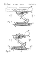
- FIG. 1 is a side elevation view of the mounting apparatus according to the present invention, with a different orientation being shown in phantom lines;
- FIG. 2 is a side elevation view similar to FIG. 1, showing the mounting bracket in a different orientation;
- FIG. 3 is another side elevation view of the mounting device shown with the mounting bracket rotated and in an extended position
- FIG. 4 is a view taken along line 4 — 4 of FIG. 3 with different rotational orientations shown in phantom lines;
- FIG. 5 is a cross-sectional view of the mounting device shown with an electronic device mounted there being broken away to show particular details of construction;
- FIG. 6 is a view similar to FIG. 5 shown without the electronic device
- FIG. 7 partial view of the mounting apparatus taken along line 7 — 7 of FIG. 5, showing the latching mechanism with parts being broken away to show particular details of construction;
- FIG. 8 is a view similar to FIG. 7 but taken along line 8 — 8 of FIG. 6 with lines being broken away to show particular details of construction;
- FIG. 9 is a view taken along line 9 — 9 of FIG. 6;
- FIG. 10 is a view taken along line 10 — 10 of FIG. 3;
- FIG. 11 is a bottom view of the base shown in FIG. 10, with parts being broken away to show particular details of construction;
- FIG. 12 is a view similar to FIG. 11 showing the locking tab in a different orientation.
- FIG. 13 is an exploded view of the mounting bracket of the present invention.
- Apparatus 10 is used to hold an electronic device 12 on a surface, such as a vehicle dash.
- Electronic device 12 can be, for example, a global positioning satellite device.
- Such a device normally includes some type of viewing screen, which visually conveys information to the user of the device.
- Apparatus 10 includes a base 14 and a mounting bracket 16 .
- base 14 is coupled to the desired surface and is used to releasably hold mounting bracket 16 .
- Bracket 16 is releasably coupled to the electronic device and is constructed to be releasably held within base 14 .
- Base 14 is constructed and assembled as described in a co-pending patent application, filed Nov. 16, 1998 entitled Mounting Apparatus For An Electronic Device, the specification of which is hereby incorporated by reference.
- base 14 has a lower section 18 with an exterior surface 20 , which has an inset 22 formed therein.
- Inset 22 is used to attach exterior surface 20 to the desired surface, such as a vehicle dash.
- an adhesive material may be applied within inset 22 , which can then be placed on the desired surface.
- a suitable adhesive putty may be used to attach base 14 to the desired surface, with inset 22 controlling the location of the putty.
- Base 14 further has a locking tab 24 held between lower section 18 and an upper section 26 .
- Tab 24 has an outwardly extending handle 28 that is connected to an operative key section 30 .
- handle 28 and key section 30 are integrally formed from one piece.
- Handle 28 may be equipped with an enlarged head 32 for easier grasping by the user thereof.
- Key section 30 has a u-shaped slot 34 formed therein which is used to either prevent or allow bracket 16 to be removed from base 14 , as is more fully described below.
- Located about one portion of the outer perimeter of key section 30 is an arcuate slot 36 . As best seen in FIGS. 11 and 12, the outermost wall 38 defining slot 36 is relatively thin and has a depression 40 formed in each end thereof
- Upper section 26 has a first gap 42 and a second gap 44 formed therein.
- First gap 42 allows clearance for handle 28 of locking tab 24 , and allows clearance for rotational movement of handle 28 about an axis in the center of key section 30 .
- Second gap 44 allows clearance for a locking arm, as is more fully described below.
- Located within upper section 26 are a number of threaded columns 46 .
- a screw 48 is placed through lower section 18 and is threaded into each column 46 , thereby securing lower section 18 to upper section 26 .
- a series of arcuate retaining walls 50 is located within the interior of upper section 26 .
- Walls 50 are located to form a perimeter that is slightly larger that the outer perimeter of key section 30 , and act to retain key section 30 within walls 50 .
- the two shorter walls 50 are spaced from one another to allow clearance for handle 28 , and to allow clearance for rotational movement of the handle.
- the two shorter walls 50 are spaced a corresponding distance to match the size of first gap 42 .
- the space between each of the shorter walls 50 and longer wall 50 allows clearance for a locking arm, as is more fully described below.
- Longer wall 50 has a detent 52 formed therein.
- Detent 52 is flexibly mounted within upper section 26 , so that it can move toward and away from locking tab 24 . In use, as is more fully described below, detent 52 is located within one of the two depressions 40 to hold locking tab 24 in either an open or a closed position. Upper section 26 further has a c-shaped cut-out 54 extending therethrough. Cut-out 54 is generally located between one of the shorter walls 50 and the longer wall 50 . Cut-out 54 allows clearance for a locking arm 56 .
- Locking arm 56 is secured within upper section 26 at a location distal from second gap 44 .
- Arm 56 is secured to upper section 26 with a suitable attaching mechanism, such as a screw or rivet, as shown at 58 .
- a suitable attaching mechanism such as a screw or rivet
- Other suitable attaching mechanisms could be used, so long as one end of arm 56 is secured to upper section 26 .
- Arm 56 has an elongated portion terminating at a button 60 .
- the elongated portion has a width that is slightly less than the width of slot 34 in key section 30 , so that it may pass between slot 34 , when slot 34 is in alignment with arm 56 .
- Button 60 is shaped to fit within cut-out 54 so that it may travel within the cut-out, and is sized to extend beyond the perimeter of upper section 26 . As best seen in FIG.
- button 60 is preferably generally oval in shape and has a spring chamber 62 formed in the bottom thereof. As best seen in FIG. 5, chamber 62 is used to locate and retain a spring 64 between button 60 and lower section 18 . Spring 64 operates to bias arm 56 upwardly, the importance of which is described below.
- a hollow 66 is presented to assist the user in comfortably depressing arm 56 .
- an arcuate retaining ridge 68 and a pawl surface 70 are presented to assist the user in comfortably depressing arm 56 .
- Both ridge 68 and pawl surface 70 are distal from hollow 66 .
- Ridge 68 is arcuate in shape and is formed by a vertical wall terminating at the upper-most surface of button 60 .
- pawl surface 70 is a series of ridges, extending from ridge 68 to the end of button 60 , and is located below the upper-most surface of button 60 .
- the exterior portion of upper section 26 includes an elevated shoulder 72 that defines a receiving slot 74 .
- Slot 74 is generally c-shaped and has a generally semi-circular portion and an extending portion which is tapered outwardly. The outward taper is used to guide bracket 16 into place, as is more fully described below.
- shoulder 72 extends outwardly over slot 74 and defines a receiving channel that is shaped as is slot 74 .
- locking tab 24 is placed on lower section 18 and within arcuate retaining walls 50 of upper section 26 .
- Tab 24 is located such that detent 52 is within one of the depressions 40 , with handle 28 protruding from upper section 26 through first gap 42 .
- Locking arm 56 is secured to upper section 26 and spring 64 is placed within chamber 62 to bias arm 56 upwardly.
- Upper section 26 and lower section 18 are then secured together by placing screws 48 through lower section 18 and threading them into columns 46 .
- tab 24 may be rotated between two positions, and held in one of two positions by locating detent 52 within one of the two depressions 40 .
- slot 34 is placed in alignment with the elongated portion of arm 56 .
- arm 56 can be moved downwardly by depressing button 60 .
- Button 60 is allowed enough clearance to place retaining ridge 68 below the adjacent surface of upper section 26 .
- slot 34 is oriented at an angle relative to the elongated portion of arm 56 .
- arm 56 and button 60 are prevented from moving downwardly. If button 60 is pressed when locking tab 24 is in this position, arm 56 is prevented from downward movement by key section 30 , because slot 34 is not aligned with arm 56 .
- retaining ridge 68 and pawl surface 70 are both positively held above the adjacent surface of upper section 26 .
- Bracket 16 is used to secure electronic device 12 in place on a surface, in cooperation with bracket 16 .
- bracket 16 includes a support 76 which is preferably made from a molded plastic.
- Support 76 has a pedestal 78 extending downwardly therefrom.
- pedestal 78 is preferably cylindrical and includes a platform 80 .
- Platform 80 has a slightly larger radius than the adjacent portion of pedestal 78 .
- platform 80 has a lower ratchet surface 82 , as best seen in FIG. 9 .
- pedestal 78 and platform 80 are placed within slot 74 of base 14 . In this orientation, a portion of ratchet surface 82 engages pawl surface 70 of locking arm 56 .
- Support 76 further has a pair of outer legs 84 and a number of braces 86 extending from its upper surface. At the outer most end of legs 84 and braces 86 are a pair of pivot bushings 88 . As best seen in FIG. 13, pivot bushings 88 are arranged so that a gap extends therebetween. Preferably, bushings 88 are integrally formed with legs 84 and braces 86 to be an integral part of support 76 . Extending through both bushings 88 is a hole 90 . Both bushings 88 are therefore similar in many respects. However, a threaded insert is inserted in the outer end of one pivot bushing 88 .
- the insert is threaded to receive the threaded end of a pivot rod, as is more fully described below.
- An end cap 92 is inserted into this pivot bushing 88 to hide the threaded insert from view.
- Surrounding hole 90 on the surface of bushings 88 nearest the gap between the bushings is an annular toothed surface (not shown).
- Bracket 16 further includes a pivot link 94 .
- link 94 is preferably generally Y-shaped.
- Link 94 has a first end 96 that is approximately the same width as the gap between bushings 88 .
- End 96 has a hole extending therethrough that can be placed in alignment with hole 90 .
- Surrounding the hole on each outer side of end 96 is an annular toothed surface. This toothed surface is preferably of the same diameter as the toothed surface surrounding hole 90 and is formed to engage and interlock therewith.
- Link 94 has a second end 98 that is equipped with a pair of upwardly extending arms 100 that form a gap or opening extending between the two arms.
- Each arm 100 is equipped with a pivot bushing 102 .
- bushings 102 are integrally formed with link 94 .
- Each bushing 102 has a hole 103 extending therethrough.
- each bushing 102 has an annular toothed surface 104 extending about hole 103 on the side of arm 100 adjacent the gap between the two arms.
- One bushing 102 has a threaded insert (not shown) press-fit therein, that allows a pivot rod to be secured therein, as is more fully described below.
- the bushing 102 having the threaded insert therein has an end cap 106 inserted into the outside thereof to hide the threaded insert from view.
- Link 94 is pivotally coupled to support 76 by placing a pivot rod 108 through pivot bushings 88 and the hole in end 96 . More specifically, rod 108 is threaded into the threaded insert in one bushing 88 . When this is done, the toothed surfaces of bushings 88 will be engaged and held against the toothed surfaces surrounding the hole in end 96 of pivot link 94 . This will prevent pivot link 94 from rotating with respect to support 76 .
- bracket 16 further includes a cradle 110 which is used to hold and receive the electronic device 12 and which is pivotally connected to second end 98 of link 94 .
- Cradle 110 has a rear cover 112 , a latch mechanism 114 and a front cover 116 .
- Rear cover 112 includes a pair of integral pivot bushings 118 that extend away from the rear surface of cover 112 . Extending through bushings 118 is a hole 120 .
- Surrounding hole 120 on the outer surface of pivot bushings 118 is a toothed annular surface 122 , which is formed to matingly connect with toothed surfaces 104 . The distance between each toothed surface 122 is approximately equal to the gap formed between arms 100 .
- near pivot bushings 118 and extending through rear cover 112 are a pair of holes 124 which are used to couple rear cover 112 to front cover 116 , as is more fully described below.
- the unexposed or interior side of rear cover 112 is formed to have a latch chamber 126 and a spring receiving chamber 128 , which accommodate latch mechanism 114 .
- Latch mechanism 114 is located between rear cover 112 and front cover 116 .
- Mechanism 114 includes a latch release 130 that is equipped with a push lever 132 , that extends outwardly of the interior of covers 112 and 116 .
- Extending from lever 132 into the interior of cradle 110 is an elongated portion 134 of release 130 .
- Portion 134 includes a pair of slide rails 136 , one surface of which rests upon and within latch chamber 126 .
- Portion 134 also includes a camming area 138 , extending through which is a camming opening 140 .
- opening 140 is preferably triangular in shape and oriented so as to have a diagonal leg extending across portion 134 .
- Opening 140 has a follower retaining notch 141 located therein which acts to positively retain a cam follower, as is described below.
- Release 130 is allowed to travel back and forth within chamber 126 , sliding along rails 136 .
- Latch mechanism 114 further includes a device latch 142 .
- Latch 142 has a cam follower 144 extending downwardly therefrom, as best seen in FIGS. 7 and 8.
- follower 144 is cylindrically shaped and located to travel within camming opening 140 . In the closed position, follower 144 is retained within notch 141 , as shown in FIG. 7 .
- spring retainer 146 located on the lower surface of latch 142 .
- Retainer 146 includes a somewhat circular member 148 and a confining member 150 . Members 148 and 150 are located a selected distance from one another so that they fit within spring receiving chamber 128 . In use, latch 142 travels within latch chamber 126 .
- cam follower 144 is located within cam opening 140 .
- a spring 154 is placed within spring retainer 146 by locating it between members 148 and 150 .
- Extending from the upper surface of latch 142 is a catch 152 that is shaped to engage electronic device 12 and hold device 12 against and within cradle 110 .
- front cover 112 With latch mechanism 114 within latch chamber 126 , rear cover 112 is secured to front cover 116 .
- cover 116 has a pair of theaded columns 156 which are located to align with holes 124 .
- Front cover 116 has extending from its lower surface a latch chamber that aligns with chamber 126 and is used to contain and guide latch mechanism 114 . More specifically, as best seen in FIGS. 7 and 8, the latch chamber is provided a pair of latch guide rails 160 and a pair of release guide rails 162 . Latch release 130 travels within rails 162 and latch 142 travels within rails 160 .
- Extending through front cover 116 is a catch opening 164 . Opening 164 is located to align with catch 152 of device latch 142 . Opening 164 is sized to be larger than catch 152 to allow catch 152 to travel longitudinally along opening 164
- the upper surface of front cover 116 is shaped to receive the electronic device 12 .
- Device 12 can be coupled to cradle 110 with latch mechanism 114 .
- the upper surface of front cover 116 has a pair of retaining ears 166 which cooperate with latch mechanism 114 to retain electronic device 12 within cradle 110 .
- Attached to the upper surface of front cover 116 adjacent catch opening 164 is a biasing mechanism 168 .
- mechanism 168 is made from a resilient sponge rubber material which acts to exert an outward force on electronic device 12 after it has been placed in cradle 110 .
- Cradle 110 is held within mounting bracket 16 by placing a pivot rod 170 through holes 103 of pivot bushings 102 and hole 120 on rear cover 112 .
- toothed surface 122 aligns with toothed surfaces 104 .
- Pivot rod 170 may be equipped with a knob on one end and has a threaded end which can be inserted into and threaded into the threaded insert in one bushing 102 . When the knob of rod 170 is fully tightened so that the threaded end is fully received within the threaded insert, surfaces 104 interlock with toothed surfaces 122 , preventing cradle 110 from moving with respect to pivot link 94 .
- electronic device 12 is placed within bracket 16 by coupling the device within cradle 110 . More specifically, catch 152 is placed within a receiving chamber on device 12 . Catch 152 is able to travel longitudinally within catch opening 164 . Catch 152 is cammed in one direction, against the bias of spring 154 , upon placing device 12 within cradle 110 . Once the catch is within the receiving chamber of device 12 , it is moved by spring 154 into a holding relationship with device 12 . To release device 12 from cradle 110 , latch release 130 is pushed inwardly by pushing on push lever 132 . This motion forces cam follower 144 to travel along the diagonal surface of camming opening 140 , which in turn forces latch 142 into a position which allows removal of the device.
- Apparatus 10 therefore allows the device to be quickly and easily removed from base 14 with one hand by depressing push lever 132 and therefore maintains the portability of device 12 .
- Device 12 therefore maintains portability, while allowing it to be mounted within a vehicle for optimal viewing.
- the base 14 is first secured to the desired surface, such as a vehicle dash, by exposing an adhesive in the area of inset 22 , or by placing an adhesive putty in the area of inset 22 .
- locking tab 24 is moved to an open position, such that slot 34 is aligned with the elongated portion of locking arm 56 .
- Pedestal 78 is then located within the base. More specifically, platform 80 is guided within the receiving channel of upper section 26 , being guided along slot 74 . Because locking tab 24 is in the open position, locking arm 56 is free to move downwardly. Thus, as platform 80 is placed on upper section 26 , it can depress locking arm 56 and platform 80 can be moved into slot 74 .
- Device 12 may be placed in any of a number of discrete rotational locations, as shown in FIG. 4, as pawl surface 70 is located along lower ratchet surface 82 . This rotational movement allows device 12 to be positioned for the driver or passenger of the vehicle, as desired.
- locking tab 24 can be rotated to a closed position. In this position, slot 34 is not aligned with the elongated portion of locking arm 56 . Therefore, in this position, pawl surface 70 is positively held against ratchet surface 82 . The engagement of pawl surface 70 and ratchet surface 82 prevents further rotation of device 12 with respect to base 14 . Further, in this position, retaining ridge 68 is positively held against platform 80 , holding device 12 within base 14 .
- Device 12 can be pivoted upwardly and downwardly through bracket 16 , as well as inwardly and outwardly. More specifically, if it is desired to reposition device 12 , pivot rods 108 and 170 can be loosened. This allows cradle 110 to be pivoted with respect to link 94 , and allows link 94 to be pivoted with respect to support 76 , because the respective toothed surfaces are not held positively against one another. Such repositioning may be necessary, for example, depending on the slope of a vehicle's dashboard. Once cradle 110 and link 94 are moved into the desired orientation, pivot rods 108 and 170 can be tightened, securing device 12 and mounting bracket 16 in position by positively holding mating toothed surfaces against one another.
- the viewing screen of device 12 can be optimally positioned for viewing by the user thereof.
- Apparatus 10 allows the device to be repositioned into a number of different orientations to optimize this viewing and allows the device to be secured in the desired orientation.
- device 12 can be placed relatively close to and parallel with base 14 . In this orientation, base 14 , bracket 16 and electronic device 12 form a relatively compact assembly.
- device 12 can be raised to an angled position. This is accomplished by loosening rods 108 and 170 . Pivot link 94 is therefore allowed to pivot about both rods into a desired orientation for electronic device 12 . Thereafter, rods 108 and 170 can be tightened, thus securing the electronic device 12 in the desired orientation.
- support 76 can be rotated to a different position from that shown in FIGS. 1 and 2. This is accomplished by releasing locking tab 24 which allows support 76 to pivot within base 14 .
- FIG. 3 also shows a more fully extended orientation for bracket 16 . Once in the desired orientation, rods 108 and 170 can be secured and locking tab 24 may be rotated to prevent support 76 from rotating out of position.
Abstract
An apparatus is provided for removably mounting an electronic device to a surface and for positioning the device with respect to the surface. The apparatus includes a cradle securable to the electronic device and a pivot link, which has a first end and a second end. The first end being pivotally coupled to the cradle. The apparatus also includes a support having a mounting pedestal coupled thereto. The second end of the pivot link is pivotally coupled to the support. The apparatus has a base which has a lower face that can be coupled to the surface and an upper face. The upper face has a receiving slot for the pedestal, the slot having a shoulder extending thereabove to engage the pedestal. The slot further has an open end to allow the pedestal to be moved within the slot. The base further includes a releasable locking arm having a retaining ridge located in line with the open end of the slot to selectively hold the pedestal within the slot. The pedestal of the apparatus can be placed within the slot and held within the slot by the retaining ridge of the locking arm. Further, the electronic device can be positioned with respect to the surface by pivoting the cradle and the link, and by rotating the pedestal within the slot.
Description
Not Applicable.
Not Applicable.
The present invention relates to a mounting apparatus for an electronic device. More specifically, the invention relates to a mounting apparatus for an electronic device for use in a vehicle, which allows the electronic device to be selectively rotated and placed in a number of positions, and which allows the electronic device to be placed within, and removed from, a mounted position with one hand.
Electronic devices are being used more and more frequently in vehicles. For example, global positioning satellite devices are currently being used in vehicles and elsewhere. These devices are used for navigational purposes and are either permanently installed in a vehicle, or mounted so as to be portable. Further, these devices have a screen which visibly communicates information to the user thereof. The portable device is advantageous in that it can be taken from the vehicle and used outside of the vehicle, thus adding value to the device.
The mounting of portable devices within vehicles does, however, present a number of disadvantages. First, it is more difficult to mount a portable device in a location within the vehicle that allows its screen to be easily viewed. Devices that are permanently installed in the vehicle can be mounted within the dashboard of the vehicle, easily within sight of the vehicle driver or passenger. Portable devices must, however, be mounted somewhere within the interior of the vehicle, such as on top of the dashboard. This mounting position presents the challenge of mounting the device in an orientation and position that can be seen and accessed.
Viewing the screen of a portable electronic device can be hampered if the angle of the viewing screen is fixed relative to the surface on which the device is mounted. A fixed viewing angle may limit the vehicles on which the device can be effectively mounted due to varying dashboard configurations as well as varying driver and passenger heights. In other words, a fixed viewing angle may impair the user's ability to effectively and comfortably view the screen. Second, these electronic devices are often under-utilized if they are only viewable by the driver of the vehicle, but not passengers riding therein. Often the passenger in the vehicle is acting as the navigator. In these situations, it is advantageous for the passenger to be able to view the global positioning satellite device.
Third, depending on the configuration of the dashboard surface on which the device is mounted, it may be necessary to either elevate or lower the device with respect to the mounting surface in order to get a clearer view of the device. A rigid mounting apparatus that does not offer the ability to manipulate the orientation of the device relative to the mounting surface is therefore disadvantageous.
As may be appreciated, it would also be advantageous to be able to place the electronic device into a mounted position using only one hand. Similarly, it would be advantageous to remove the electronic device from a mounted position using only one hand.
Therefore, a mounting apparatus is needed that can be used to mount a portable electronic device within a vehicle so that the device can be easily viewed and adjusted. Further, a mounting apparatus is needed that allows an electronic device to be mounted within a vehicle so that it is viewable by either the driver or the passenger riding therein. Still further, a mounting apparatus is needed that allows an electronic device to be mounted within, and removed from, a mounted position using only one hand. Finally, a mounting apparatus is needed that can be used to either elevate or lower, and manipulate the orientation of the device relative to the surface on which the apparatus is mounted.
It is an object of the present invention to provide a mounting apparatus for an electronic device within a vehicle so that the device can be easily viewed and that allows the angle of the device relative to the user to be adjusted.
It is a further object of this invention to provide a mounting apparatus that selectively allows either the driver or the passenger of a vehicle in which the device is mounted to view the device.
It is another feature of this invention to provide a mounting apparatus that allows a device mounted therein to be either raised or lowered, and manipulated relative to the surface on which the apparatus is mounted.
It is still another object of the present invention to provide a mounting apparatus for an electronic device that allows the electronic device to be mounted within, and removed from, a mounted position using only one hand.
According to the present invention, the foregoing and other objects are obtained by an apparatus for removably mounting an electronic device to a surface and for positioning the device with respect to the surface. The appatus includes a cradle that is adapted to be releasably secured to the electronic device and a pivot link, which has a first end and a second end, the first end being pivotally coupled to the cradle. The apparatus also includes a support having a mounting pedestal coupled thereto. The second end of the pivot link is pivotally coupled to the support. The apparatus has a base which has a lower face that can be coupled to the surface and an upper face. The upper face has a receiving slot for the pedestal, the slot having a shoulder extending thereabove to engage the pedestal. The slot further has an open end to allow the pedestal to be moved within the slot. The base further includes a releasable locking arm having a retaining ridge located in line with the open end of the slot to selectively hold the pedestal within the slot. The pedestal of the apparatus can be placed within the slot and held within the slot by the retaining ridge of the locking arm. Further, the electronic device can be positioned with respect to the surface by pivoting the cradle and the link, and by rotating the pedestal within the slot.
Additional objects, advantages, and novel features of the invention will be set forth in part in the description which follows, and in part will become apparent to those skilled in the practice of the invention. The objects and advantages of the invention may be realized and attained by means of the instrumentalities and combinations particularly pointed out in the appended claims.
In the accompanying drawings which form a part of the specification and which are to be read in conjunction therewith and in which like reference numerals are used to indicate like parts in the various views:
FIG. 1 is a side elevation view of the mounting apparatus according to the present invention, with a different orientation being shown in phantom lines;
FIG. 2 is a side elevation view similar to FIG. 1, showing the mounting bracket in a different orientation;
FIG. 3 is another side elevation view of the mounting device shown with the mounting bracket rotated and in an extended position;
FIG. 4 is a view taken along line 4—4 of FIG. 3 with different rotational orientations shown in phantom lines;
FIG. 5 is a cross-sectional view of the mounting device shown with an electronic device mounted there being broken away to show particular details of construction;
FIG. 6 is a view similar to FIG. 5 shown without the electronic device;
FIG. 7 partial view of the mounting apparatus taken along line 7—7 of FIG. 5, showing the latching mechanism with parts being broken away to show particular details of construction;
FIG. 8 is a view similar to FIG. 7 but taken along line 8—8 of FIG. 6 with lines being broken away to show particular details of construction;
FIG. 9 is a view taken along line 9—9 of FIG. 6;
FIG. 10 is a view taken along line 10—10 of FIG. 3;
FIG. 11 is a bottom view of the base shown in FIG. 10, with parts being broken away to show particular details of construction;
FIG. 12 is a view similar to FIG. 11 showing the locking tab in a different orientation; and
FIG. 13 is an exploded view of the mounting bracket of the present invention.
Referring initially to FIGS. 1 and 2, a mounting embodying the principles of this invention is broadly designated in the drawings by reference numeral 10. Apparatus 10 is used to hold an electronic device 12 on a surface, such as a vehicle dash. Electronic device 12 can be, for example, a global positioning satellite device. Such a device normally includes some type of viewing screen, which visually conveys information to the user of the device. Apparatus 10 includes a base 14 and a mounting bracket 16. As described below, base 14 is coupled to the desired surface and is used to releasably hold mounting bracket 16. Bracket 16 is releasably coupled to the electronic device and is constructed to be releasably held within base 14.
Also located within the interior of upper section 26 is a series of arcuate retaining walls 50. As best seen in FIGS. 11 and 12, there are preferably three walls 50, with one wall being longer than the other two. Walls 50 are located to form a perimeter that is slightly larger that the outer perimeter of key section 30, and act to retain key section 30 within walls 50. The two shorter walls 50 are spaced from one another to allow clearance for handle 28, and to allow clearance for rotational movement of the handle. Generally, the two shorter walls 50 are spaced a corresponding distance to match the size of first gap 42. The space between each of the shorter walls 50 and longer wall 50 allows clearance for a locking arm, as is more fully described below. Longer wall 50 has a detent 52 formed therein. Detent 52 is flexibly mounted within upper section 26, so that it can move toward and away from locking tab 24. In use, as is more fully described below, detent 52 is located within one of the two depressions 40 to hold locking tab 24 in either an open or a closed position. Upper section 26 further has a c-shaped cut-out 54 extending therethrough. Cut-out 54 is generally located between one of the shorter walls 50 and the longer wall 50. Cut-out 54 allows clearance for a locking arm 56.
Locking arm 56 is secured within upper section 26 at a location distal from second gap 44. Arm 56 is secured to upper section 26 with a suitable attaching mechanism, such as a screw or rivet, as shown at 58. Other suitable attaching mechanisms could be used, so long as one end of arm 56 is secured to upper section 26. Arm 56 has an elongated portion terminating at a button 60. The elongated portion has a width that is slightly less than the width of slot 34 in key section 30, so that it may pass between slot 34, when slot 34 is in alignment with arm 56. Button 60 is shaped to fit within cut-out 54 so that it may travel within the cut-out, and is sized to extend beyond the perimeter of upper section 26. As best seen in FIG. 12, button 60 is preferably generally oval in shape and has a spring chamber 62 formed in the bottom thereof. As best seen in FIG. 5, chamber 62 is used to locate and retain a spring 64 between button 60 and lower section 18. Spring 64 operates to bias arm 56 upwardly, the importance of which is described below. As best seen in FIG. 10, on the upper surface of button 60, a hollow 66 is presented to assist the user in comfortably depressing arm 56. Also on the upper surface of button 60 is an arcuate retaining ridge 68 and a pawl surface 70. Both ridge 68 and pawl surface 70 are distal from hollow 66. Ridge 68 is arcuate in shape and is formed by a vertical wall terminating at the upper-most surface of button 60. As best seen in FIG. 10, pawl surface 70 is a series of ridges, extending from ridge 68 to the end of button 60, and is located below the upper-most surface of button 60.
The exterior portion of upper section 26 includes an elevated shoulder 72 that defines a receiving slot 74. Slot 74 is generally c-shaped and has a generally semi-circular portion and an extending portion which is tapered outwardly. The outward taper is used to guide bracket 16 into place, as is more fully described below. As best seen in FIG. 10, shoulder 72 extends outwardly over slot 74 and defines a receiving channel that is shaped as is slot 74.
In assembling base 14, locking tab 24 is placed on lower section 18 and within arcuate retaining walls 50 of upper section 26. Tab 24 is located such that detent 52 is within one of the depressions 40, with handle 28 protruding from upper section 26 through first gap 42. Locking arm 56 is secured to upper section 26 and spring 64 is placed within chamber 62 to bias arm 56 upwardly. Upper section 26 and lower section 18 are then secured together by placing screws 48 through lower section 18 and threading them into columns 46. With this construction, tab 24 may be rotated between two positions, and held in one of two positions by locating detent 52 within one of the two depressions 40. When rotating tab 24 between the two positions, detent 52 slides along the thin portion of wall 38 and forces it slightly inwardly, due to an inward bias of detent 52. In one position, slot 34 is placed in alignment with the elongated portion of arm 56. In this position, arm 56 can be moved downwardly by depressing button 60. Button 60 is allowed enough clearance to place retaining ridge 68 below the adjacent surface of upper section 26. In the other position, slot 34 is oriented at an angle relative to the elongated portion of arm 56. In this position, arm 56 and button 60 are prevented from moving downwardly. If button 60 is pressed when locking tab 24 is in this position, arm 56 is prevented from downward movement by key section 30, because slot 34 is not aligned with arm 56. In this position, retaining ridge 68 and pawl surface 70 are both positively held above the adjacent surface of upper section 26.
As best seen in FIG. 13, bracket 16 further includes a cradle 110 which is used to hold and receive the electronic device 12 and which is pivotally connected to second end 98 of link 94. Cradle 110 has a rear cover 112, a latch mechanism 114 and a front cover 116. Rear cover 112 includes a pair of integral pivot bushings 118 that extend away from the rear surface of cover 112. Extending through bushings 118 is a hole 120. Surrounding hole 120 on the outer surface of pivot bushings 118 is a toothed annular surface 122, which is formed to matingly connect with toothed surfaces 104. The distance between each toothed surface 122 is approximately equal to the gap formed between arms 100. As best seen in FIGS. 7 and 8, near pivot bushings 118 and extending through rear cover 112 are a pair of holes 124 which are used to couple rear cover 112 to front cover 116, as is more fully described below.
The unexposed or interior side of rear cover 112 is formed to have a latch chamber 126 and a spring receiving chamber 128, which accommodate latch mechanism 114. Latch mechanism 114 is located between rear cover 112 and front cover 116. Mechanism 114 includes a latch release 130 that is equipped with a push lever 132, that extends outwardly of the interior of covers 112 and 116. Extending from lever 132 into the interior of cradle 110 is an elongated portion 134 of release 130. Portion 134 includes a pair of slide rails 136, one surface of which rests upon and within latch chamber 126. Portion 134 also includes a camming area 138, extending through which is a camming opening 140. As best seen in FIGS. 7, 8 and 13, opening 140 is preferably triangular in shape and oriented so as to have a diagonal leg extending across portion 134. Opening 140 has a follower retaining notch 141 located therein which acts to positively retain a cam follower, as is described below. Release 130 is allowed to travel back and forth within chamber 126, sliding along rails 136.
With latch mechanism 114 within latch chamber 126, rear cover 112 is secured to front cover 116. As best in FIG. 13, cover 116 has a pair of theaded columns 156 which are located to align with holes 124. To secure rear cover 112 to front cover 116 a pair of screws 158 are threaded into columns 156 after being placed through holes 124. Front cover 116 has extending from its lower surface a latch chamber that aligns with chamber 126 and is used to contain and guide latch mechanism 114. More specifically, as best seen in FIGS. 7 and 8, the latch chamber is provided a pair of latch guide rails 160 and a pair of release guide rails 162. Latch release 130 travels within rails 162 and latch 142 travels within rails 160. Extending through front cover 116 is a catch opening 164. Opening 164 is located to align with catch 152 of device latch 142. Opening 164 is sized to be larger than catch 152 to allow catch 152 to travel longitudinally along opening 164.
The upper surface of front cover 116 is shaped to receive the electronic device 12. Device 12 can be coupled to cradle 110 with latch mechanism 114. More specifically, the upper surface of front cover 116 has a pair of retaining ears 166 which cooperate with latch mechanism 114 to retain electronic device 12 within cradle 110. Attached to the upper surface of front cover 116 adjacent catch opening 164 is a biasing mechanism 168. Preferably, mechanism 168 is made from a resilient sponge rubber material which acts to exert an outward force on electronic device 12 after it has been placed in cradle 110.
In use, electronic device 12 is placed within bracket 16 by coupling the device within cradle 110. More specifically, catch 152 is placed within a receiving chamber on device 12. Catch 152 is able to travel longitudinally within catch opening 164. Catch 152 is cammed in one direction, against the bias of spring 154, upon placing device 12 within cradle 110. Once the catch is within the receiving chamber of device 12, it is moved by spring 154 into a holding relationship with device 12. To release device 12 from cradle 110, latch release 130 is pushed inwardly by pushing on push lever 132. This motion forces cam follower 144 to travel along the diagonal surface of camming opening 140, which in turn forces latch 142 into a position which allows removal of the device. Apparatus 10 therefore allows the device to be quickly and easily removed from base 14 with one hand by depressing push lever 132 and therefore maintains the portability of device 12. Device 12 therefore maintains portability, while allowing it to be mounted within a vehicle for optimal viewing.
To secure device 12 within a vehicle, the base 14 is first secured to the desired surface, such as a vehicle dash, by exposing an adhesive in the area of inset 22, or by placing an adhesive putty in the area of inset 22. To mount device 12 within base 14, locking tab 24 is moved to an open position, such that slot 34 is aligned with the elongated portion of locking arm 56. Pedestal 78 is then located within the base. More specifically, platform 80 is guided within the receiving channel of upper section 26, being guided along slot 74. Because locking tab 24 is in the open position, locking arm 56 is free to move downwardly. Thus, as platform 80 is placed on upper section 26, it can depress locking arm 56 and platform 80 can be moved into slot 74.
When platform 80 is moved completely within slot 74, its outer perimeter will clear button 60 up to retaining ridge 68. Spring 64 will then act to move locking arm 56 upwardly and pawl surface 70 will be placed in engagement with ratchet surface 82 of platform 80. Retaining ridge 68 will then be in engagement with the outer perimeter of platform 80. In this orientation, bracket 16 and device 12 are prevented from moving beyond base 14 by retaining ridge 68. In order to remove device 12 from base 14, button 60 of locking arm 56 must be depressed to release retaining ridge 68 from engagement with platform 80. Further, in this orientation, device 12 can be rotated with respect to base 14. In this rotation, enough rotational force must be applied to overcome the spring force acting upwardly on pawl surface 70. Device 12 may be placed in any of a number of discrete rotational locations, as shown in FIG. 4, as pawl surface 70 is located along lower ratchet surface 82. This rotational movement allows device 12 to be positioned for the driver or passenger of the vehicle, as desired.
Once device 12 has been rotated to the desired location, locking tab 24 can be rotated to a closed position. In this position, slot 34 is not aligned with the elongated portion of locking arm 56. Therefore, in this position, pawl surface 70 is positively held against ratchet surface 82. The engagement of pawl surface 70 and ratchet surface 82 prevents further rotation of device 12 with respect to base 14. Further, in this position, retaining ridge 68 is positively held against platform 80, holding device 12 within base 14.
From the above movements, the viewing screen of device 12 can be optimally positioned for viewing by the user thereof. Apparatus 10 allows the device to be repositioned into a number of different orientations to optimize this viewing and allows the device to be secured in the desired orientation. As seen in FIG. 1, device 12 can be placed relatively close to and parallel with base 14. In this orientation, base 14, bracket 16 and electronic device 12 form a relatively compact assembly. As best seen in FIG. 2, device 12 can be raised to an angled position. This is accomplished by loosening rods 108 and 170. Pivot link 94 is therefore allowed to pivot about both rods into a desired orientation for electronic device 12. Thereafter, rods 108 and 170 can be tightened, thus securing the electronic device 12 in the desired orientation. Moreover, as best seen in FIG. 3, support 76 can be rotated to a different position from that shown in FIGS. 1 and 2. This is accomplished by releasing locking tab 24 which allows support 76 to pivot within base 14. FIG. 3 also shows a more fully extended orientation for bracket 16. Once in the desired orientation, rods 108 and 170 can be secured and locking tab 24 may be rotated to prevent support 76 from rotating out of position.
From the foregoing, it will be seen that this invention is one well adapted to attain all the ends and objects hereinabove set forth together with other advantages which are obvious and which are inherent to the structure. It will be understood that certain features and subcombinations are of utility and may be employed without reference to other features and subcombinations. This is contemplated by and is within the scope of the claims.
Since many possible embodiments may be made of the invention without departing from the scope thereof, it is to be understood that all matter herein set forth or shown in the accompanying drawings is to be interpreted as illustrative and not in a limiting sense.
Claims (26)
1. An apparatus for removably mounting a portable, handheld electronic device to a surface and for positioning the device with respect to the surface, comprising:
a cradle adapted to be releasably secured to the portable, handheld electronic device;
a pivot link, having a first end and a second end, said second end being pivotally coupled to said cradle;
a support having a mounting pedestal coupled thereto, said first end of said pivot link being pivotally coupled to said support; and
a base having a lower section adapted to be coupled to the surface, and having an upper section adapted to rotatingly and releasably receive the pedestal of said support;
wherein said upper section has a receiving slot for said pedestal, said slot having a shoulder extending thereabove to engage said pedestal and an open end adaopted to allow said pedestal to be moved within said slot, said base further including a releasable locking arm having a retaining ridge located in line with said open end of said slot, said arm thereby being adapted to selectively hold said pedestal within said slot; and
wherein said pedestal can be placed within said upper section, and wherein the electronic device can be positioned with respect to the surface by pivoting said cradle and said link with respect to said support, and by rotating said pedestal within said upper section.
2. The apparatus of claim 1, wherein said pedestal has a lower ratchet surface and said locking arm has an upper pawl surface located to engage said ratchet surface when said pedestal is located within said slot, said ratchet and pawl surface providing a mechanism to hold said support and the electronic device in a desired rotational position.
3. The apparatus of claim 2, further comprising a biasing mechanism to bias said locking arm upwardly so that said retaining ridge engages said pedestal and so that said pawl surface engages said ratchet surface.
4. The apparatus of claim 3, further comprising a locking tab held between said lower section and said upper section of said base, said locking tab being rotatable between a first position that prevents disengagement of said pawl surface and said ratchet surface and a second position that allows disengagement of said pawl surface and said ratchet surface.
5. An apparatus for removably mounting a global positioning satellite device to a vehicle surface, comprising:
a cradle adapted to be secured to the global positioning device;
a pivot link, having a first end and a second end, said second end being pivotally coupled to said cradle;
a support having a mounting pedestal coupled thereto, said first end of said pivot link being pivotally coupled to said support;
a base having a lower section adapted to be coupled to the vehicle surface, and an upper section having a receiving slot for said pedestal, said slot having a shoulder extending thereabove to engage said pedestal and an open end adapted to allow said pedestal to be moved within said slot; and
a releasable locking arm coupled to said base, said arm having a retaining ridge located in line with said open end of said slot and positioned to selectively hold said pedestal within said slot,
wherein said pedestal is adapted to be placed within said slot and held within said slot by said retaining ridge of said locking arm, and wherein the global positioning device can be positioned with respect to the vehicle surface by pivoting said cradle and said link with respect to said support, and by rotating said pedestal within said slot.
6. The apparatus of claim 5, wherein said pedestal has a lower ratchet surface and said locking arm has an upper pawl surface located to engage said ratchet surface when said pedestal is located within said slot, said ratchet surface and pawl surface providing a mechanism to hold said support and the global positioning device in a desired rotational position.
7. The apparatus of claim 6, further comprising a biasing mechanism to bias said locking arm upwardly so that said retaining ridge engages said pedestal and so that said pawl surface engages said ratchet surface.
8. The apparatus of claim 7, further comprising a locking tab held between said upper face and said lower face of said base, said locking tab being rotatable between a first position that prevents disengagement of said pawl surface and said ratchet surface and a second position that allows disengagement of said pawl surface and said ratchet surface.
9. The apparatus of claim 5, further comprising a locking mechanism operably coupled between said cradle and said pivot link, said locking mechanism adapted to selectively prevent pivotal movement of said cradle with respect to said pivot link.
10. The apparatus of claim 9, further comprising a second locking mechanism operably coupled between said pivot link and said support, said second locking mechanism adapted to selectively prevent pivotal movement of said pivot link and said support.
11. The apparatus of claim 10, wherein said cradle contains a releasable latching mechanism adapted to releasably engage the global positioning device, said mechanism having a moveable catch which protrudes upwardly from said cradle and which is adapted to releasably hold said device within said cradle.
12. An apparatus for removably mounting a portable, handheld electronic device to a surface and for positioning the device with respect to the surface, comprising:
an articulating mounting bracket having at least two pivot points and adapted to releasably hold the portable, handheld electronic device, wherein said mounting bracket further comprises a cradle for releasably securing the portable, handheld electronic device, wherein said cradle includes a portion for at least partially surrounding the electronic device; and
a holder for releasably and rotatingly holding said bracket and for coupling said bracket to the surface,
wherein said holder is adapted to be coupled to the surface, and wherein the electronic device can be positioned with respect to the surface by pivoting said bracket about the pivot points and by rotating said bracket within said holding means.
13. The apparatus of claim 12, wherein said bracket further comprises:
a pivot link, having a first end and a second end, said second end being pivotally coupled to said cradle; and
a support having a mounting pedestal coupled thereto, said first end of said pivot link being pivotally coupled to said support.
14. The apparatus of claim 13, further comprising a locking mechanism operably coupled between said cradle and said pivot link.
15. The apparatus of claim 13, further comprising a second locking mechanism operably coupled between said pivot link and said support.
16. The apparatus of claim 12, wherein said cradle contains a releasable latching mechanism that releasably engages the electronic device, said mechanism having moveable finger which protrudes upwardly from a surface of said cradle to hold said device within said cradle.
17. A mounting assembly in combination with a portable, handheld electronic device having a back face and a front face, the front face having a display, wherein the back face of the electronic device is adapted to be held in a palm of a hand of a user, said combination comprising:
a cradle for releasably securing the portable, handheld electronic device such that the back face rests against the cradle;
a pivot link, having a first end and a second end, said second end being pivotally coupled to said cradle;
support having a mounting pedestal coupled thereto, said first end of said pivot link being pivotally coupled to said support; and
a base having a lower section adapted to be coupled to the surface, and having an upper section adapted to rotatingly and releasably receive the pedestal of said support, wherein said upper section has a receiving slot for said pedestal, said slot having a shoulder extending thereabove to engage said pedestal and an open end adapted to allow said pedestal to be moved within said slot, said base further including a releasable locking arm having a retaining ridge located in line with said open end of said slot, said arm thereby being adapted to selectively hold said pedestal within said slot, and
wherein said pedestal can be placed within said upper section, and wherein the electronic device can be positioned with respect to the surface by pivoting said cradle and said link with respect to said support, and by rotating said pedestal within said upper section.
18. The combination of claim 17, wherein said pedestal has a lower ratchet surface and said locking arm has an upper pawl surface located to engage said ratchet surface when said pedestal is located within said slot, said ratchet and pawl surface providing a mechanism to hold said support and the electronic device in a desired rotational position.
19. The combination of claim 18, further comprising a biasing mechanism to bias said locking arm upwardly so that said retaining ridge engages said pedestal and so that said pawl surface engages said ratchet surface.
20. The combination of claim 19, further comprising a locking tab held between said lower section and said upper section of said base, said locking tab being rotatable between a first position that prevents disengagement of said pawl surface and said ratchet surface and a second position that allows disengagement of said pawl surface and said ratchet surface.
21. An apparatus for removably mounting a portable, handheld electronic device to a surface and for positioning the device with respect to the surface, comprising:
a cradle for releasably securing the portable, electronic device;
a pivot link, having a first end and a second end, said second end being pivotally coupled to said cradle;
a support having a mounting pedestal coupled thereto, said first end of said pivot link being pivotally coupled to said support;
a base having a lower section adapted to be coupled to the surface, and having an upper section adapted to rotatingly and releasably receive the pedestal of said support; and
a locking mechanism operably coupled between said cradle and said pivot link, said locking mechanism adapted to selectively prevent pivotal movement of said cradle with respect to said pivot link,
wherein said pedestal can be placed within said upper section, and wherein the electronic device can be positioned with respect to the surface by pivoting said cradle and said link with respect to said support, and by rotating said pedestal within said upper section.
22. The apparatus of claim 21, further comprising a second locking mechanism operably coupled between said pivot link and said support, said second locking mechanism adapted to selectively prevent pivotal movement of said link with respect to said support.
23. The apparatus of claim 22, wherein said cradle contains a releasable latching mechanism adapted to releasably engage the electronic device, said mechanism having a moveable release, said release being operable with one hand to release said mechanism from engagement with the device.
24. A mounting assembly in combination with a portable, handheld electronic device having a back face and a front face, the front face having a display, wherein the back face of the electronic device is adapted to be held in a palm of a hand of a user, said combination comprising:
a cradle for releasably securing the portable, handheld electronic device such that the back face rests against the cradle;
a pivot link, having a first end and a second end, said second end being pivotally coupled to said cradle;
a support having a mounting pedestal coupled thereto, said first end of said pivot link being pivotally coupled to said support;
a base having a lower section adapted to be coupled to the surface, and having an upper section adapted to rotatingly and releasably receive the pedestal of said support; and
a locking mechanism operably coupled between said cradle and said pivot link, said locking mechanism adapted to selectively prevent pivotal movement of said cradle with respect to said pivot link,
wherein said pedestal can be placed within said upper section, and wherein the electronic device can be positioned with respect to the surface by pivoting said cradle and said link with respect to said support, and by rotating said pedestal within said upper section.
25. The combination of claim 24, further comprising a second locking mechanism operably coupled between said pivot link and said support, said second locking mechanism adapted to selectively prevent pivotal movement of said link with respect to said support.
26. The combination of claim 25, wherein said cradle contains a releasable latching mechanism adapted to releasably engage the electronic device, said mechanism having a moveable release, said release being operable with one hand to release said mechanism from engagement with the device.
Priority Applications (3)
| Application Number | Priority Date | Filing Date | Title |
|---|---|---|---|
| US09/208,348 US6173933B1 (en) | 1998-12-09 | 1998-12-09 | Multi-position articulating mounting apparatus for an electronic device |
| US09/452,409 US6464185B1 (en) | 1998-11-16 | 1999-12-01 | Multi-position articulating mounting apparatus for an electronic device |
| US10/413,166 US7380759B1 (en) | 1998-11-16 | 2003-04-14 | Multi-position articulating mounting apparatus for an electronic device |
Applications Claiming Priority (1)
| Application Number | Priority Date | Filing Date | Title |
|---|---|---|---|
| US09/208,348 US6173933B1 (en) | 1998-12-09 | 1998-12-09 | Multi-position articulating mounting apparatus for an electronic device |
Related Parent Applications (1)
| Application Number | Title | Priority Date | Filing Date |
|---|---|---|---|
| US09/192,919 Continuation-In-Part US6129321A (en) | 1998-11-16 | 1998-11-16 | Mounting apparatus for an electronic device |
Related Child Applications (1)
| Application Number | Title | Priority Date | Filing Date |
|---|---|---|---|
| US09/452,409 Continuation US6464185B1 (en) | 1998-11-16 | 1999-12-01 | Multi-position articulating mounting apparatus for an electronic device |
Publications (1)
| Publication Number | Publication Date |
|---|---|
| US6173933B1 true US6173933B1 (en) | 2001-01-16 |
Family
ID=22774263
Family Applications (2)
| Application Number | Title | Priority Date | Filing Date |
|---|---|---|---|
| US09/208,348 Expired - Lifetime US6173933B1 (en) | 1998-11-16 | 1998-12-09 | Multi-position articulating mounting apparatus for an electronic device |
| US09/452,409 Expired - Lifetime US6464185B1 (en) | 1998-11-16 | 1999-12-01 | Multi-position articulating mounting apparatus for an electronic device |
Family Applications After (1)
| Application Number | Title | Priority Date | Filing Date |
|---|---|---|---|
| US09/452,409 Expired - Lifetime US6464185B1 (en) | 1998-11-16 | 1999-12-01 | Multi-position articulating mounting apparatus for an electronic device |
Country Status (1)
| Country | Link |
|---|---|
| US (2) | US6173933B1 (en) |
Cited By (85)
| Publication number | Priority date | Publication date | Assignee | Title |
|---|---|---|---|---|
| US6244553B1 (en) * | 2000-02-02 | 2001-06-12 | Chin-Yang Wang | Fastening device for electronic equipment |
| US6382577B1 (en) * | 1999-12-15 | 2002-05-07 | Group Dekko Services, Llc | Articulated support device |
| US6427959B1 (en) | 2000-11-27 | 2002-08-06 | Garmin Corporation | Mounting bracket for an electronic device |
| US6464185B1 (en) * | 1998-11-16 | 2002-10-15 | Garmin Corporation | Multi-position articulating mounting apparatus for an electronic device |
| US20030068986A1 (en) * | 2001-10-09 | 2003-04-10 | Samsung Electronics Co., Ltd. | Apparatus to mount a mobile device in a vehicle |
| WO2004001567A2 (en) * | 2002-06-19 | 2003-12-31 | Motion Computing, Inc. | Tablet computing device with three-dimensional docking support |
| US6793187B2 (en) | 2002-11-27 | 2004-09-21 | Mcgee Harry L. | Movable mounting bracket arm assembly |
| US20040262479A1 (en) * | 2003-06-30 | 2004-12-30 | Lowrance Electronics, Inc. | Mounting assembly |
| US20050028325A1 (en) * | 2003-08-07 | 2005-02-10 | Carnevali Jeffrey D. | Secure interface cradle for pocket personal computer device |
| US20050029424A1 (en) * | 2003-08-06 | 2005-02-10 | Liu Alvin (Chien-Chung) | Adjusting assembly for LCD monitor |
| US20050088811A1 (en) * | 2003-10-22 | 2005-04-28 | Imran Ulla | External battery pack |
| US20050121578A1 (en) * | 2003-08-27 | 2005-06-09 | Saeb Asamarai | Locking joint for support arm |
| US20050213297A1 (en) * | 2003-10-22 | 2005-09-29 | Motion Computing, Inc. | Extended peripheral battery pack for a tablet computer |
| US20050213298A1 (en) * | 2002-06-19 | 2005-09-29 | Motion Computing, Inc. | Docking support for a tablet computer with extended battery |
| US6966533B1 (en) | 2003-05-05 | 2005-11-22 | Garmin Ltd. | Mounting apparatus for an electronic device |
| US20050257352A1 (en) * | 2003-08-07 | 2005-11-24 | Carnevali Jeffrey D | Quick draw cradle apparatus |
| US20050268825A1 (en) * | 2004-05-27 | 2005-12-08 | Steelcase Development Corporation | Two person work environment |
| US20060026807A1 (en) * | 2003-08-07 | 2006-02-09 | Carnevali Jeffrey D | Quick release mounting apparatus |
| US20060058941A1 (en) * | 1999-04-19 | 2006-03-16 | Dekock Bruce W | System for providing traffic information |
| US20060054751A1 (en) * | 2004-09-15 | 2006-03-16 | Johnson Brian B | Vertically-adjustable mobile computer workstation and method of using same |
| US20060164036A1 (en) * | 2005-01-21 | 2006-07-27 | Motion Computing, Inc. | Systems for powering peripheral devices |
| US20060181637A1 (en) * | 2005-02-16 | 2006-08-17 | Innovative Office Products, Inc. | Quick release assembly for an electronic device |
| US20060285306A1 (en) * | 2005-05-24 | 2006-12-21 | Carnevali Jeffrey D | Secure universal mounting apparatus |
| US20070012839A1 (en) * | 2005-07-14 | 2007-01-18 | Garmin Ltd., A Cayman Islands Corporation | Mount assembly for electronic devices |
| US20070016184A1 (en) * | 2005-07-14 | 2007-01-18 | Ethicon Endo-Surgery, Inc. | Medical-treatment electrode assembly and method for medical treatment |
| US20070022582A1 (en) * | 2005-07-28 | 2007-02-01 | Carnevali Jeffrey D | Thumb release mounting apparatus |
| US20070022583A1 (en) * | 2005-07-28 | 2007-02-01 | Carnevali Jeffrey D | Thumb release mounting apparatus |
| US20070040084A1 (en) * | 2005-06-03 | 2007-02-22 | Lane Sturman | Support arm assembly |
| US20070158516A1 (en) * | 2003-02-21 | 2007-07-12 | Ching-Hsien Huang | Liquid crystal display |
| US20070207842A1 (en) * | 2006-03-06 | 2007-09-06 | Garmin Ltd. A Cayman Islands Corporation | Electronic device mount |
| US7313477B1 (en) | 2004-04-29 | 2007-12-25 | Garmin Ltd. | Vehicle dash-mounted navigation device |
| US7363148B1 (en) | 2003-03-26 | 2008-04-22 | Garmin Ltd. | Navigational device for installation in a vehicle and a method for doing same |
| US7380759B1 (en) | 1998-11-16 | 2008-06-03 | Garmin Corporation | Multi-position articulating mounting apparatus for an electronic device |
| US20080296449A1 (en) * | 2007-05-31 | 2008-12-04 | Carnevali Jeffrey D | Quick release electronics platform |
| US20080296821A1 (en) * | 2007-05-31 | 2008-12-04 | Carnevali Jeffrey D | Quick release electronics platform |
| US20080312829A1 (en) * | 2007-06-15 | 2008-12-18 | Allen David W | Navigation system with swivel sensor mount |
| US20090212189A1 (en) * | 2007-05-31 | 2009-08-27 | Carnevali Jeffrey D | Quick release electronics platform |
| US20090229936A1 (en) * | 2008-03-13 | 2009-09-17 | Targus Group International, Inc. | Portable computer case |
| US20090250570A1 (en) * | 2008-04-08 | 2009-10-08 | Garmin Ltd. | Mount for an electronic device |
| US7623958B1 (en) | 2003-03-26 | 2009-11-24 | Garmin Ltd. | Navigational device for installation in a vehicle and a method for doing same |
| US7650230B1 (en) * | 2003-03-26 | 2010-01-19 | Garmin Ltd. | Navigational device for mounting on a support pillar of a vehicle and a method for doing same |
| US20100096515A1 (en) * | 2007-10-12 | 2010-04-22 | Joel Hazzard | Convertible Display Stand System and Method |
| US20100193649A1 (en) * | 2009-02-02 | 2010-08-05 | Garmin Ltd. | Mount for an electronic device |
| US7908080B2 (en) | 2004-12-31 | 2011-03-15 | Google Inc. | Transportation routing |
| CN102026510A (en) * | 2010-12-20 | 2011-04-20 | 鸿富锦精密工业(深圳)有限公司 | Electronic device and support thereof |
| US7987046B1 (en) | 2007-04-04 | 2011-07-26 | Garmin Switzerland Gmbh | Navigation device with improved user interface and mounting features |
| US7988106B2 (en) | 2007-02-23 | 2011-08-02 | Carnevali Jeffrey D | Adaptive mounting structure |
| US20110223802A1 (en) * | 2010-03-11 | 2011-09-15 | Garmin Ltd. | Mounting assembly for an electronic device |
| CN101754614B (en) * | 2008-12-22 | 2012-07-25 | 深圳富泰宏精密工业有限公司 | Portable electronic device |
| USD684982S1 (en) | 2010-08-11 | 2013-06-25 | Colebrook Bosson Saunders (Products) Limited | Display support with indicator window |
| JP2013147197A (en) * | 2012-01-20 | 2013-08-01 | Tsuchiya Yac Corp | Suction cup type in-vehicle monitor attachment tool |
| USD705764S1 (en) | 2012-09-12 | 2014-05-27 | Targus Group International, Inc. | Wallet portable electronic device case |
| US8746449B2 (en) | 2010-06-07 | 2014-06-10 | Targus Group International, Inc. | Portable electronic device case accessories and related systems and methods |
| US8763795B1 (en) | 2013-01-23 | 2014-07-01 | Targus Group International, Inc. | Dual support flap case |
| USD716783S1 (en) | 2013-04-15 | 2014-11-04 | Targus Group International, Inc. | Slim case |
| US9074721B2 (en) | 2010-06-09 | 2015-07-07 | Alex Lau | Support system |
| US9110630B2 (en) | 2013-07-25 | 2015-08-18 | Targus Group International, Inc. | Portable electronic device case with an adhesive panel |
| US9132779B2 (en) | 2013-11-04 | 2015-09-15 | Omix-Ada, Inc. | Multi-device dash mount for vehicles |
| CN105065888A (en) * | 2015-08-07 | 2015-11-18 | 陈桂霞 | Tablet computer bracket used on bed |
| US20150350397A1 (en) * | 2012-12-28 | 2015-12-03 | Faurecia Interieur Industrie | Holder device for portable electronic apparatus, inner structure and vehicle including such a device |
| US9316346B2 (en) | 2010-06-09 | 2016-04-19 | Colebrook Bosson Saunders (Products) Limited | Support system |
| USD765016S1 (en) | 2014-09-04 | 2016-08-30 | Omix-Ada, Inc. | Multi-device dash mount for vehicles |
| US20160363262A1 (en) * | 2015-06-10 | 2016-12-15 | Connor Moelmann | Mounting Device |
| US9532474B2 (en) | 2015-01-21 | 2016-12-27 | Garmin Switzerland Gmbh | Device mounting system with locking lever |
| CN106379248A (en) * | 2016-10-18 | 2017-02-08 | 成都益睿信科技有限公司 | Vehicle-mounted multi-angle electronic product support frame convenient to use |
| US9675148B2 (en) | 2015-03-18 | 2017-06-13 | Targus International Llc | Extendable, universal case for portable electronic devices |
| US9717314B2 (en) | 2014-06-27 | 2017-08-01 | Targus International Llc | Case for portable electronic devices with shutter stand |
| US9750321B2 (en) | 2014-06-13 | 2017-09-05 | Targus Group International, Inc. | Case for portable electronic devices with internal support |
| CN107344459A (en) * | 2016-05-06 | 2017-11-14 | 力山工业股份有限公司 | Multi-functional microscope carrier |
| US20180084655A1 (en) * | 2016-09-21 | 2018-03-22 | Systems And Software Enterprises, Llc | Display Unit for a Vehicle |
| US9933109B2 (en) | 2015-06-03 | 2018-04-03 | Dgm Enterprises Llc | Vibration resistant equipment mount |
| US10136715B2 (en) * | 2014-12-18 | 2018-11-27 | Hand Held Products, Inc. | Wearable sled system for a mobile computer device |
| CN109017601A (en) * | 2018-07-06 | 2018-12-18 | 广州番客信息科技有限公司 | Automobile tire pressure monitoring equipment based on Internet of things |
| CN109606275A (en) * | 2018-12-28 | 2019-04-12 | 保汇通(厦门)网络科技有限公司 | A kind of automobile data recorder bracket of adjustable-angle |
| US20190126415A1 (en) * | 2016-04-14 | 2019-05-02 | Rem Industrie S.R.L. | Device for mounting a blank on a modular supporting system |
| US10330251B2 (en) | 2016-11-24 | 2019-06-25 | Jeffrey D. Carnevali | Finger grip mounting apparatus |
| US10334936B2 (en) | 2009-05-06 | 2019-07-02 | Tumi, Inc. | Checkpoint-friendly backpack |
| US10503207B1 (en) * | 2018-12-12 | 2019-12-10 | Dell Products, L.P. | Dock for a multi-form factor information handling system (IHS) |
| CN111204292A (en) * | 2018-11-22 | 2020-05-29 | 韦巴斯托股份公司 | Device and method for adjusting a display assembly and roof for a motor vehicle |
| US10782732B2 (en) * | 2013-09-21 | 2020-09-22 | Otter Products, Llc | Mounting system for electronic device |
| USD936969S1 (en) | 2020-01-31 | 2021-11-30 | Targus International Llc | Pocket for portable electronic device |
| US11191178B2 (en) | 2019-01-24 | 2021-11-30 | Steelcase Inc. | Display support system and method for the use thereof |
| CN113771770A (en) * | 2021-10-27 | 2021-12-10 | 三旗(惠州)电子科技有限公司 | Self-warning vehicle-mounted navigator with oxygen content detection function |
| US11647834B2 (en) | 2020-07-23 | 2023-05-16 | Steelcase Inc. | Display support system and method for the use thereof |
| US20230382285A1 (en) * | 2022-05-27 | 2023-11-30 | Ford Global Technologies, Llc | Vehicle having deployable sliding work desk |
Families Citing this family (63)
| Publication number | Priority date | Publication date | Assignee | Title |
|---|---|---|---|---|
| DE20313215U1 (en) * | 2003-08-25 | 2003-10-16 | Richter Herbert | holder |
| US6663064B1 (en) * | 1999-12-01 | 2003-12-16 | Garmin Corporation | Multi-position articulating mounting apparatus for an electronic device |
| US20030030620A1 (en) * | 2001-08-08 | 2003-02-13 | International Business Machines Corporation | Adjustable display device |
| TW539380U (en) * | 2002-02-20 | 2003-06-21 | Hannstar Display Corp | Flat display device angle adjustment mechanism |
| US6713678B2 (en) * | 2002-03-11 | 2004-03-30 | Sun Microsystems, Inc. | Cable management system for electronic devices such as flat panel monitors |
| US6927682B1 (en) * | 2002-12-21 | 2005-08-09 | Jeff Touhey | Digital vehicle service indicator |
| DE10329784B3 (en) * | 2003-07-01 | 2004-12-16 | Siemens Ag | Attachment for charge computer to motor vehicle has mounting arm associated with computer with pivot axis, free end designed for attachment to vehicle windscreen with computer supported on windscreen |
| US7317611B2 (en) * | 2003-07-23 | 2008-01-08 | Chief Manufacturing Inc. | Under-cabinet mount for flat-panel displays |
| US20050110913A1 (en) * | 2003-11-07 | 2005-05-26 | Vitito Christopher J. | Automobile entertainment system |
| US20060070103A1 (en) * | 2003-11-07 | 2006-03-30 | Vitito Christopher J | Vehicle entertainment system |
| US20050099547A1 (en) * | 2003-11-07 | 2005-05-12 | Vitito Christopher J. | Automobile entertainment system |
| US8780282B2 (en) * | 2003-11-07 | 2014-07-15 | Voxx International Corporation | Vehicle entertainment system |
| US20050242636A1 (en) * | 2003-11-07 | 2005-11-03 | Vitito Christopher J | Vehicle entertainment system with a rear loading DVD player |
| US7360833B2 (en) * | 2003-11-07 | 2008-04-22 | Vitito Christopher J | Vehicle entertainment system with backside loading DVD player |
| US20050235327A1 (en) * | 2003-11-07 | 2005-10-20 | Vitito Christopher J | Vehicle entertainment system |
| US20050242637A1 (en) * | 2003-11-07 | 2005-11-03 | Vitito Christopher J | Vehicle entertainment system with a side loading DVD player |
| US20050110313A1 (en) * | 2003-11-07 | 2005-05-26 | Vitito Christopher J. | Housing for an automobile entertainment system |
| US20050099548A1 (en) * | 2003-11-07 | 2005-05-12 | Vitito Christopher J. | Automobile entertainment system |
| US7604273B2 (en) * | 2003-11-07 | 2009-10-20 | Vitito Christopher J | Vehicle entertainment system |
| GB0405794D0 (en) * | 2004-03-15 | 2004-04-21 | Tomtom Bv | Dock for a portable navigation device |
| WO2005124058A2 (en) * | 2004-06-11 | 2005-12-29 | Custom Plastics, Inc. | Flat screen monitor desktop support |
| US8120716B2 (en) * | 2005-06-16 | 2012-02-21 | Audiovox Corporation | Vehicle entertainment system including monitor for rear view enhancement |
| US20060283299A1 (en) * | 2005-06-16 | 2006-12-21 | Design For Living, L.L.C. | Food slicer with suction device and adjustable cutting surface |
| US7699376B2 (en) * | 2005-06-16 | 2010-04-20 | Vitito Christopher J | Vehicle entertainment system with retaining mechanism |
| US20070070595A1 (en) * | 2005-09-28 | 2007-03-29 | Enlight Corporation | Screwless device for attaching and detaching disk drive |
| KR101239979B1 (en) * | 2006-03-08 | 2013-03-06 | 삼성전자주식회사 | Display apparatus |
| US8567740B2 (en) * | 2006-03-23 | 2013-10-29 | Byron Richard Tarnutzer | Deployable support unit for reading material |
| US20110180682A1 (en) * | 2006-03-23 | 2011-07-28 | Byron Richard Tarnutzer | Deployable support unit for reading material |
| US7828260B2 (en) * | 2006-03-23 | 2010-11-09 | Hauser Stephen G | Deployable support unit for reading material |
| JP4902306B2 (en) * | 2006-09-28 | 2012-03-21 | 株式会社カサタニ | Equipment support stand |
| DE202007005661U1 (en) * | 2007-04-19 | 2007-07-05 | Buchhalter, Thomas | Implement holder has mounting plate is fastened by mounting plate in close proximity of driver on instrument panel |
| US8016107B2 (en) * | 2007-12-27 | 2011-09-13 | Timothy Emsky | Holder for portable electronic device |
| DE202008005583U1 (en) * | 2008-04-22 | 2008-07-10 | Kienzle Argo Taxi International Gmbh | Taxametersystem |
| CN101362449B (en) * | 2008-07-17 | 2010-06-02 | 旭丽电子(广州)有限公司 | Fixture unit for vehicle |
| FR2946299B1 (en) * | 2009-06-08 | 2011-06-17 | Peugeot Citroen Automobiles Sa | RETRACTABLE SUPPORT DEVICE CLEAR TO BE SUBSTANTIALLY VERTICALLY RANGED IN A VEHICLE RECEPTACLE AND TO SUPPORT AT LEAST ONE OBJECT IN DEPLOYED POSITION |
| CN102473022B (en) | 2009-07-22 | 2014-11-05 | 惠普开发有限公司 | Modular flat-panel monitor stand |
| US8191838B2 (en) * | 2009-12-02 | 2012-06-05 | Domestic Investments Group, LLC | Collapsible and adjustable electronics support systems |
| WO2011101083A1 (en) * | 2010-01-28 | 2011-08-25 | Kinetix Ag | Device for attaching a tablet computer |
| US9296340B2 (en) | 2010-01-28 | 2016-03-29 | Kinetix Ag | Device for attaching a tablet computer |
| US9074725B2 (en) * | 2010-07-29 | 2015-07-07 | Kevin Trotsky | Mobile electronic device positioning unit |
| US8611076B2 (en) | 2011-01-13 | 2013-12-17 | Autumn Horizons, Inc. | Multi-positional stand and under cabinet mount for a tablet computer |
| CN102826045B (en) * | 2011-06-13 | 2014-12-10 | 富泰华工业(深圳)有限公司 | Supporting device |
| DE102011118740B3 (en) * | 2011-11-17 | 2013-04-11 | Wirkner Gmbh | Holding unit for mobile device, such as mobile telephone or navigation device, particularly for fastening to vehicles or in passenger compartment of passenger car, has receiving element for the mobile device and fastening element |
| US10196850B2 (en) | 2013-01-07 | 2019-02-05 | WexEnergy LLC | Frameless supplemental window for fenestration |
| US9691163B2 (en) | 2013-01-07 | 2017-06-27 | Wexenergy Innovations Llc | System and method of measuring distances related to an object utilizing ancillary objects |
| US9234381B2 (en) | 2013-01-07 | 2016-01-12 | WexEnergy LLC | Supplemental window for fenestration |
| US9663983B2 (en) | 2013-01-07 | 2017-05-30 | WexEnergy LLC | Frameless supplemental window for fenestration incorporating infiltration blockers |
| US9845636B2 (en) | 2013-01-07 | 2017-12-19 | WexEnergy LLC | Frameless supplemental window for fenestration |
| CN103192771B (en) * | 2013-03-15 | 2015-12-02 | 杜浩明 | Automatic stationary type onboard digital equipment supporter |
| WO2014176115A1 (en) * | 2013-04-22 | 2014-10-30 | Ar Tables, Llc | Apparatus for hands-free augmented reality viewing |
| KR101569020B1 (en) * | 2013-12-12 | 2015-11-13 | 엘지전자 주식회사 | Holder device for portable terminal |
| US9609105B1 (en) | 2015-02-05 | 2017-03-28 | Allstate Insurance Company | Phone holder |
| US9278652B1 (en) | 2015-02-05 | 2016-03-08 | Allstate Insurance Company | Phone holder |
| US9699285B1 (en) | 2015-02-05 | 2017-07-04 | Allstate Insurance Company | Phone holder |
| US9859940B1 (en) | 2015-02-05 | 2018-01-02 | Allstate Insurance Company | Phone holder |
| US9281857B1 (en) | 2015-02-05 | 2016-03-08 | Allstate Insurance Company | Phone holder |
| CN104908670A (en) * | 2015-06-23 | 2015-09-16 | 陈元喜 | Automobile data recorder fixing frame with power supplied by solar energy |
| TWM539214U (en) * | 2016-12-30 | 2017-04-01 | 信錦企業股份有限公司 | Quick release pivot module and supporting device |
| RU175531U1 (en) * | 2017-03-31 | 2017-12-07 | Федеральное государственное казенное военное образовательное учреждение высшего образования "ВОЕННАЯ АКАДЕМИЯ МАТЕРИАЛЬНО-ТЕХНИЧЕСКОГО ОБЕСПЕЧЕНИЯ имени генерала армии А.В. Хрулева" | Improved device for securing the key input unit for the 2B17 Tornado-g |
| CN111247304B (en) | 2017-05-30 | 2023-01-13 | 韦克斯能源有限责任公司 | Frameless auxiliary window for window arrangement |
| CN107323370A (en) * | 2017-07-05 | 2017-11-07 | 重庆长野汽车配件有限公司 | A kind of sun-proof type automobile navigation instrument support |
| US10890207B2 (en) | 2017-07-06 | 2021-01-12 | Vertiball Solutions Ltd. | Connection to a suction disc |
| DE202021102428U1 (en) * | 2021-05-05 | 2021-05-14 | Kinetix Ag | Holder for releasable attachment of a flat device to a motor vehicle seat |
Citations (30)
| Publication number | Priority date | Publication date | Assignee | Title |
|---|---|---|---|---|
| US600535A (en) | 1898-03-15 | William c | ||
| US1638716A (en) | 1925-08-07 | 1927-08-09 | Lawrence O Surles | Spotlight |
| US2371451A (en) | 1944-10-04 | 1945-03-13 | Warren H Larson | Universal indicator clamp |
| US2528201A (en) | 1947-12-08 | 1950-10-31 | Starrett L S Co | Clamp |
| US3126191A (en) | 1964-03-24 | holden | ||
| US3312436A (en) | 1965-07-09 | 1967-04-04 | Jr Raymond A Beghetto | Vessel holder |
| US4162696A (en) | 1977-04-02 | 1979-07-31 | Rollei-Werke Franke & Heidecke | Support for a camera |
| US4270721A (en) | 1978-09-22 | 1981-06-02 | Mainor Jr Ross F | Instrument support |
| US4687167A (en) * | 1985-10-23 | 1987-08-18 | Skalka Gerald P | Multi-position computer support |
| US4956756A (en) | 1989-02-10 | 1990-09-11 | Hsiao Wen J | Table lamp adapter system |
| USD312650S (en) | 1987-04-24 | 1990-12-04 | Charrier V Jean | Bean bag camera support |
| USD314713S (en) | 1988-11-18 | 1991-02-19 | Magellan Systems Corporation | Navigation device |
| US5092552A (en) * | 1982-10-04 | 1992-03-03 | Wang Laboratories, Inc. | Ergonomic equipment arm |
| US5204817A (en) | 1990-02-15 | 1993-04-20 | Clarion Co. Ltd. | Car mounted navigation system |
| US5263423A (en) | 1992-02-07 | 1993-11-23 | Rolf Anderson | Article securement device |
| US5326059A (en) | 1992-12-23 | 1994-07-05 | Pryor Products | Quick clamping system |
| US5332185A (en) | 1993-06-08 | 1994-07-26 | Walker Iii Fred M | Gun rest |
| US5339222A (en) | 1993-04-06 | 1994-08-16 | The Whitaker Corporation | Shielded printed circuit card holder |
| US5337985A (en) | 1993-03-05 | 1994-08-16 | Hale Alan P | Support device for a laptop computer |
| US5350147A (en) | 1993-10-19 | 1994-09-27 | Paganus Thomas J | Omnipositional pod for camera |
| US5429336A (en) * | 1994-03-30 | 1995-07-04 | Ko; Hsiwng C. | Wall rack having a turnable support frame and a plastic bushing in a pivot seat thereof |
| US5476241A (en) | 1993-11-12 | 1995-12-19 | David L. Helman | Wheelchair accessory stand |
| US5503361A (en) | 1993-04-26 | 1996-04-02 | Nec Corporation | Adjustable stand device |
| US5918841A (en) * | 1996-06-07 | 1999-07-06 | Ergotron, Inc. | Computer keyboard and flat panel display cart |
| US5931102A (en) * | 1997-06-02 | 1999-08-03 | Grahl Industries, Inc. | Ergonomic support device |
| US5938159A (en) * | 1997-07-10 | 1999-08-17 | Hung; Teng-Shun | Computer monitor supporting bracket |
| US5964443A (en) * | 1997-08-13 | 1999-10-12 | Cipa - Usa, Inc. | Mounting bracket system for a rearview mirror |
| US5975474A (en) * | 1995-11-22 | 1999-11-02 | Steelcase Inc. | Articulated keyboard shelf |
| US5996954A (en) * | 1997-10-14 | 1999-12-07 | Rosen Products Llc | Stowable support apparatus |
| US6012693A (en) * | 1998-02-19 | 2000-01-11 | Ergotron, Inc. | Multi-function display mounting system |
Family Cites Families (19)
| Publication number | Priority date | Publication date | Assignee | Title |
|---|---|---|---|---|
| US1266367A (en) * | 1915-05-08 | 1918-05-14 | Ira H Wilson | Adjustable support or rest. |
| US1995656A (en) * | 1934-01-11 | 1935-03-26 | George H Stout | Adjustable bracket |
| US2720372A (en) * | 1953-05-22 | 1955-10-11 | Gordon D Gowan | Swivel adapter for mounting a camera on a tripod |
| US4592526A (en) * | 1981-08-24 | 1986-06-03 | Jacob Kobelt | Adjustable holding device |
| US4834329A (en) * | 1987-05-29 | 1989-05-30 | Michael Delapp | Monitor support for a terminal |
| US4797916A (en) * | 1987-11-13 | 1989-01-10 | Uniden Corporation Of America | Telephone handset cradle mounting |
| US4989813A (en) * | 1989-11-29 | 1991-02-05 | Samsung Electron Devices Co., Ltd. | Supporting base for controlling height, swivel and inclination of display means |
| EP0445331A1 (en) * | 1990-03-07 | 1991-09-11 | First National Investments Ltd. | Pivoting arm for a carrier plate, especially a video display unit carrier plate |
| US5154390A (en) * | 1991-08-30 | 1992-10-13 | Bain Charles E | Articulated stand for supporting object |
| US5655736A (en) * | 1994-06-30 | 1997-08-12 | Kozloff; Matthew S. | Retaining device for an electronic signalling device |
| US5452874A (en) * | 1994-06-30 | 1995-09-26 | Kozloff; Matthew S. | Retainer device for an electronic signalling device |
| US6089520A (en) * | 1996-09-03 | 2000-07-18 | Mag Technology Co., Ltd. | Swivel base structure |
| KR100255765B1 (en) * | 1997-07-09 | 2000-05-01 | 구자홍 | Front and rear regulation support structure of monitor |
| KR19990032025U (en) * | 1997-12-31 | 1999-07-26 | 윤종용 | SWIVEL device of flat panel display device |
| US6027257A (en) * | 1998-03-26 | 2000-02-22 | Basic Telepresence Inc | Pan and tilt unit |
| US6129321A (en) * | 1998-11-16 | 2000-10-10 | Garmin Corporation | Mounting apparatus for an electronic device |
| US6173933B1 (en) * | 1998-12-09 | 2001-01-16 | Garmin Corporation | Multi-position articulating mounting apparatus for an electronic device |
| US6079682A (en) * | 1998-12-23 | 2000-06-27 | Nokia Mobile Phones Limited | Apparatus for mounting a mobile device on a support surface |
| US6213438B1 (en) * | 1999-12-16 | 2001-04-10 | Ostby Leroy M. | Computer support for vehicle use having multiple position adjustments |
-
1998
- 1998-12-09 US US09/208,348 patent/US6173933B1/en not_active Expired - Lifetime
-
1999
- 1999-12-01 US US09/452,409 patent/US6464185B1/en not_active Expired - Lifetime
Patent Citations (32)
| Publication number | Priority date | Publication date | Assignee | Title |
|---|---|---|---|---|
| US600535A (en) | 1898-03-15 | William c | ||
| US3126191A (en) | 1964-03-24 | holden | ||
| US1638716A (en) | 1925-08-07 | 1927-08-09 | Lawrence O Surles | Spotlight |
| US2371451A (en) | 1944-10-04 | 1945-03-13 | Warren H Larson | Universal indicator clamp |
| US2528201A (en) | 1947-12-08 | 1950-10-31 | Starrett L S Co | Clamp |
| US3312436A (en) | 1965-07-09 | 1967-04-04 | Jr Raymond A Beghetto | Vessel holder |
| US4162696A (en) | 1977-04-02 | 1979-07-31 | Rollei-Werke Franke & Heidecke | Support for a camera |
| US4270721A (en) | 1978-09-22 | 1981-06-02 | Mainor Jr Ross F | Instrument support |
| US5092552A (en) * | 1982-10-04 | 1992-03-03 | Wang Laboratories, Inc. | Ergonomic equipment arm |
| US4687167A (en) * | 1985-10-23 | 1987-08-18 | Skalka Gerald P | Multi-position computer support |
| USD312650S (en) | 1987-04-24 | 1990-12-04 | Charrier V Jean | Bean bag camera support |
| USD314713S (en) | 1988-11-18 | 1991-02-19 | Magellan Systems Corporation | Navigation device |
| US4956756A (en) | 1989-02-10 | 1990-09-11 | Hsiao Wen J | Table lamp adapter system |
| US5204817A (en) | 1990-02-15 | 1993-04-20 | Clarion Co. Ltd. | Car mounted navigation system |
| US5263423A (en) | 1992-02-07 | 1993-11-23 | Rolf Anderson | Article securement device |
| US5326059A (en) | 1992-12-23 | 1994-07-05 | Pryor Products | Quick clamping system |
| US5337985A (en) | 1993-03-05 | 1994-08-16 | Hale Alan P | Support device for a laptop computer |
| US5339222A (en) | 1993-04-06 | 1994-08-16 | The Whitaker Corporation | Shielded printed circuit card holder |
| US5503361A (en) | 1993-04-26 | 1996-04-02 | Nec Corporation | Adjustable stand device |
| US5332185A (en) | 1993-06-08 | 1994-07-26 | Walker Iii Fred M | Gun rest |
| US5350147A (en) | 1993-10-19 | 1994-09-27 | Paganus Thomas J | Omnipositional pod for camera |
| US5476241A (en) | 1993-11-12 | 1995-12-19 | David L. Helman | Wheelchair accessory stand |
| US5429336A (en) * | 1994-03-30 | 1995-07-04 | Ko; Hsiwng C. | Wall rack having a turnable support frame and a plastic bushing in a pivot seat thereof |
| US5975474A (en) * | 1995-11-22 | 1999-11-02 | Steelcase Inc. | Articulated keyboard shelf |
| US5918841A (en) * | 1996-06-07 | 1999-07-06 | Ergotron, Inc. | Computer keyboard and flat panel display cart |
| US5924665A (en) * | 1996-06-07 | 1999-07-20 | Ergotron, Inc. | Ceiling system for a flat panel display |
| US5967479A (en) * | 1996-06-07 | 1999-10-19 | Ergotron, Inc. | Keyboard tray on support arm with pivoting brake |
| US5931102A (en) * | 1997-06-02 | 1999-08-03 | Grahl Industries, Inc. | Ergonomic support device |
| US5938159A (en) * | 1997-07-10 | 1999-08-17 | Hung; Teng-Shun | Computer monitor supporting bracket |
| US5964443A (en) * | 1997-08-13 | 1999-10-12 | Cipa - Usa, Inc. | Mounting bracket system for a rearview mirror |
| US5996954A (en) * | 1997-10-14 | 1999-12-07 | Rosen Products Llc | Stowable support apparatus |
| US6012693A (en) * | 1998-02-19 | 2000-01-11 | Ergotron, Inc. | Multi-function display mounting system |
Cited By (147)
| Publication number | Priority date | Publication date | Assignee | Title |
|---|---|---|---|---|
| US7380759B1 (en) | 1998-11-16 | 2008-06-03 | Garmin Corporation | Multi-position articulating mounting apparatus for an electronic device |
| US6464185B1 (en) * | 1998-11-16 | 2002-10-15 | Garmin Corporation | Multi-position articulating mounting apparatus for an electronic device |
| US20060058941A1 (en) * | 1999-04-19 | 2006-03-16 | Dekock Bruce W | System for providing traffic information |
| US6382577B1 (en) * | 1999-12-15 | 2002-05-07 | Group Dekko Services, Llc | Articulated support device |
| US6244553B1 (en) * | 2000-02-02 | 2001-06-12 | Chin-Yang Wang | Fastening device for electronic equipment |
| US6427959B1 (en) | 2000-11-27 | 2002-08-06 | Garmin Corporation | Mounting bracket for an electronic device |
| US20030068986A1 (en) * | 2001-10-09 | 2003-04-10 | Samsung Electronics Co., Ltd. | Apparatus to mount a mobile device in a vehicle |
| US7103397B2 (en) * | 2001-10-09 | 2006-09-05 | Samsung Electronics Co., Ltd. | Apparatus to mount a mobile device in a vehicle |
| WO2004001567A2 (en) * | 2002-06-19 | 2003-12-31 | Motion Computing, Inc. | Tablet computing device with three-dimensional docking support |
| US6914197B2 (en) | 2002-06-19 | 2005-07-05 | Motion Computing, Inc. | Flexible circuit board for tablet computing device |
| US20040188133A1 (en) * | 2002-06-19 | 2004-09-30 | John Doherty | Tablet computing device with three-dimensional docking support |
| US20050213298A1 (en) * | 2002-06-19 | 2005-09-29 | Motion Computing, Inc. | Docking support for a tablet computer with extended battery |
| GB2406230A (en) * | 2002-06-19 | 2005-03-23 | Motion Computing Inc | Tablet computing device with three-dimensional docking support |
| WO2004001567A3 (en) * | 2002-06-19 | 2004-09-23 | Motion Computing Inc | Tablet computing device with three-dimensional docking support |
| GB2406230B (en) * | 2002-06-19 | 2006-09-20 | Motion Computing Inc | Tablet computing device with three-dimensional docking support |
| US6793187B2 (en) | 2002-11-27 | 2004-09-21 | Mcgee Harry L. | Movable mounting bracket arm assembly |
| US20070158516A1 (en) * | 2003-02-21 | 2007-07-12 | Ching-Hsien Huang | Liquid crystal display |
| US7363148B1 (en) | 2003-03-26 | 2008-04-22 | Garmin Ltd. | Navigational device for installation in a vehicle and a method for doing same |
| US7650230B1 (en) * | 2003-03-26 | 2010-01-19 | Garmin Ltd. | Navigational device for mounting on a support pillar of a vehicle and a method for doing same |
| US7623958B1 (en) | 2003-03-26 | 2009-11-24 | Garmin Ltd. | Navigational device for installation in a vehicle and a method for doing same |
| US7440845B1 (en) | 2003-03-26 | 2008-10-21 | Garmin Ltd. | Navigational device for installation in a vehicle and a method for doing same |
| US6966533B1 (en) | 2003-05-05 | 2005-11-22 | Garmin Ltd. | Mounting apparatus for an electronic device |
| US20040262479A1 (en) * | 2003-06-30 | 2004-12-30 | Lowrance Electronics, Inc. | Mounting assembly |
| US7063297B2 (en) | 2003-06-30 | 2006-06-20 | Lowrance Electronics, Inc. | Mounting assembly |
| US7520481B2 (en) | 2003-06-30 | 2009-04-21 | Navico, Inc. | Mounting assembly |
| US20050029424A1 (en) * | 2003-08-06 | 2005-02-10 | Liu Alvin (Chien-Chung) | Adjusting assembly for LCD monitor |
| US7338019B2 (en) * | 2003-08-06 | 2008-03-04 | Hon Hai Precision Ind. Co., Ltd. | Adjusting assembly for LCD monitor |
| US7571522B2 (en) | 2003-08-07 | 2009-08-11 | Carnevali Jeffrey D | Quick draw cradle apparatus |
| US20050257352A1 (en) * | 2003-08-07 | 2005-11-24 | Carnevali Jeffrey D | Quick draw cradle apparatus |
| US20060026807A1 (en) * | 2003-08-07 | 2006-02-09 | Carnevali Jeffrey D | Quick release mounting apparatus |
| US20050028325A1 (en) * | 2003-08-07 | 2005-02-10 | Carnevali Jeffrey D. | Secure interface cradle for pocket personal computer device |
| US7017243B2 (en) | 2003-08-07 | 2006-03-28 | Carnevali Jeffrey D | Secure interface cradle for pocket personal computer device |
| US20050121578A1 (en) * | 2003-08-27 | 2005-06-09 | Saeb Asamarai | Locking joint for support arm |
| US20050213297A1 (en) * | 2003-10-22 | 2005-09-29 | Motion Computing, Inc. | Extended peripheral battery pack for a tablet computer |
| US20050088811A1 (en) * | 2003-10-22 | 2005-04-28 | Imran Ulla | External battery pack |
| US7236356B2 (en) | 2003-10-22 | 2007-06-26 | Motion Computing, Inc. | External battery pack |
| US7313477B1 (en) | 2004-04-29 | 2007-12-25 | Garmin Ltd. | Vehicle dash-mounted navigation device |
| US20050268825A1 (en) * | 2004-05-27 | 2005-12-08 | Steelcase Development Corporation | Two person work environment |
| US20060283358A1 (en) * | 2004-05-27 | 2006-12-21 | Steelcase Development Corporation | Two person work environment |
| US7677182B2 (en) | 2004-05-27 | 2010-03-16 | Steelcase Development Corporation | Two person work environment |
| US20060054751A1 (en) * | 2004-09-15 | 2006-03-16 | Johnson Brian B | Vertically-adjustable mobile computer workstation and method of using same |
| US9778055B2 (en) | 2004-12-31 | 2017-10-03 | Google Inc. | Transportation routing |
| US8606514B2 (en) | 2004-12-31 | 2013-12-10 | Google Inc. | Transportation routing |
| US8798917B2 (en) | 2004-12-31 | 2014-08-05 | Google Inc. | Transportation routing |
| US9709415B2 (en) | 2004-12-31 | 2017-07-18 | Google Inc. | Transportation routing |
| US7908080B2 (en) | 2004-12-31 | 2011-03-15 | Google Inc. | Transportation routing |
| US11092455B2 (en) | 2004-12-31 | 2021-08-17 | Google Llc | Transportation routing |
| US9945686B2 (en) | 2004-12-31 | 2018-04-17 | Google Llc | Transportation routing |
| US20060164036A1 (en) * | 2005-01-21 | 2006-07-27 | Motion Computing, Inc. | Systems for powering peripheral devices |
| US7673838B2 (en) | 2005-02-16 | 2010-03-09 | Innovative Office Products, Inc. | Quick release assembly for an electronic device |
| US20060181637A1 (en) * | 2005-02-16 | 2006-08-17 | Innovative Office Products, Inc. | Quick release assembly for an electronic device |
| US7551458B2 (en) | 2005-05-24 | 2009-06-23 | Carnevali Jeffrey D | Secure universal mounting apparatus |
| US20060285306A1 (en) * | 2005-05-24 | 2006-12-21 | Carnevali Jeffrey D | Secure universal mounting apparatus |
| US20070040084A1 (en) * | 2005-06-03 | 2007-02-22 | Lane Sturman | Support arm assembly |
| US8794579B2 (en) | 2005-06-03 | 2014-08-05 | Steelcase, Inc. | Support arm assembly |
| US7475858B2 (en) | 2005-07-14 | 2009-01-13 | Garmin Ltd. | Separable ball and socket assembly for electronic device mounts |
| US7516928B2 (en) | 2005-07-14 | 2009-04-14 | Garmin Ltd. | Mount assembly for electronic devices |
| US20070012840A1 (en) * | 2005-07-14 | 2007-01-18 | Garmin Ltd.,A Cayman Islands Corporation | Separable ball and socket assembly for electronic device mounts |
| US7219867B2 (en) | 2005-07-14 | 2007-05-22 | Garmin Ltd. | Mount assembly for electronic devices |
| US20080023606A1 (en) * | 2005-07-14 | 2008-01-31 | Garmin Ltd. | Separable ball and socket assembly for electronic device mounts |
| US20070016184A1 (en) * | 2005-07-14 | 2007-01-18 | Ethicon Endo-Surgery, Inc. | Medical-treatment electrode assembly and method for medical treatment |
| US20070117419A1 (en) * | 2005-07-14 | 2007-05-24 | Garmin Ltd. | Mount assembly for electronic devices |
| US7296771B2 (en) | 2005-07-14 | 2007-11-20 | Garmin Ltd. | Separable ball and socket assembly for electronic device mounts |
| US20070012839A1 (en) * | 2005-07-14 | 2007-01-18 | Garmin Ltd., A Cayman Islands Corporation | Mount assembly for electronic devices |
| US20070022582A1 (en) * | 2005-07-28 | 2007-02-01 | Carnevali Jeffrey D | Thumb release mounting apparatus |
| US7647676B2 (en) | 2005-07-28 | 2010-01-19 | Carnevali Jeffrey D | Thumb release mounting apparatus |
| US7523528B2 (en) | 2005-07-28 | 2009-04-28 | Carnevali Jeffrey D | Thumb release mounting apparatus |
| US8176603B2 (en) | 2005-07-28 | 2012-05-15 | Carnevali Jeffrey D | Universal cradle apparatus |
| US20110057083A1 (en) * | 2005-07-28 | 2011-03-10 | Carnevali Jeffrey D | Universal cradle apparatus |
| US20070022583A1 (en) * | 2005-07-28 | 2007-02-01 | Carnevali Jeffrey D | Thumb release mounting apparatus |
| US7925320B2 (en) | 2006-03-06 | 2011-04-12 | Garmin Switzerland Gmbh | Electronic device mount |
| US20070207842A1 (en) * | 2006-03-06 | 2007-09-06 | Garmin Ltd. A Cayman Islands Corporation | Electronic device mount |
| US7988106B2 (en) | 2007-02-23 | 2011-08-02 | Carnevali Jeffrey D | Adaptive mounting structure |
| US7987046B1 (en) | 2007-04-04 | 2011-07-26 | Garmin Switzerland Gmbh | Navigation device with improved user interface and mounting features |
| US20110205697A1 (en) * | 2007-04-04 | 2011-08-25 | Garmin Switzerland Gmbh | Navigation device with improved interface and mounting features |
| US8116978B2 (en) | 2007-04-04 | 2012-02-14 | Garmin Switzerland Gmbh | Navigation device with improved interface and mounting features |
| US20080296821A1 (en) * | 2007-05-31 | 2008-12-04 | Carnevali Jeffrey D | Quick release electronics platform |
| US7823844B2 (en) | 2007-05-31 | 2010-11-02 | Carnevali Jeffrey D | Quick release electronics platform |
| US8074951B2 (en) | 2007-05-31 | 2011-12-13 | Carnevali Jeffrey D | Quick release electronics platform |
| US8091850B2 (en) | 2007-05-31 | 2012-01-10 | Carnevali Jeffrey D | Quick release electronics platform |
| US20090212189A1 (en) * | 2007-05-31 | 2009-08-27 | Carnevali Jeffrey D | Quick release electronics platform |
| US20080296449A1 (en) * | 2007-05-31 | 2008-12-04 | Carnevali Jeffrey D | Quick release electronics platform |
| US8315797B2 (en) * | 2007-06-15 | 2012-11-20 | Navigation Solutions, Llc | Navigation system with swivel sensor mount |
| US20080312829A1 (en) * | 2007-06-15 | 2008-12-18 | Allen David W | Navigation system with swivel sensor mount |
| US20100096515A1 (en) * | 2007-10-12 | 2010-04-22 | Joel Hazzard | Convertible Display Stand System and Method |
| US20090229936A1 (en) * | 2008-03-13 | 2009-09-17 | Targus Group International, Inc. | Portable computer case |
| US8567578B2 (en) | 2008-03-13 | 2013-10-29 | Targus Group International, Inc. | Portable computer case |
| US20090250570A1 (en) * | 2008-04-08 | 2009-10-08 | Garmin Ltd. | Mount for an electronic device |
| US8668179B2 (en) | 2008-04-08 | 2014-03-11 | Garmin Switzerland Gmbh | Mount for an electronic device |
| CN101754614B (en) * | 2008-12-22 | 2012-07-25 | 深圳富泰宏精密工业有限公司 | Portable electronic device |
| US20100193649A1 (en) * | 2009-02-02 | 2010-08-05 | Garmin Ltd. | Mount for an electronic device |
| US8041029B2 (en) | 2009-02-02 | 2011-10-18 | Garmin Switzerland Gmbh | Mount for an electronic device |
| US10334936B2 (en) | 2009-05-06 | 2019-07-02 | Tumi, Inc. | Checkpoint-friendly backpack |
| US20110223802A1 (en) * | 2010-03-11 | 2011-09-15 | Garmin Ltd. | Mounting assembly for an electronic device |
| US8120895B2 (en) * | 2010-03-11 | 2012-02-21 | Garmin Switzerland Gmbh | Mounting assembly having a base with an inner ball positioned within a hollow outer ball |
| US8783458B2 (en) | 2010-06-07 | 2014-07-22 | Targus Group International, Inc. | Portable electronic device case accessories and related systems and methods |
| US10139861B2 (en) | 2010-06-07 | 2018-11-27 | Targus Group International, Inc. | Portable electronic device case accessories and related systems and methods |
| US9170611B2 (en) | 2010-06-07 | 2015-10-27 | Targus Group International, Inc. | Portable electronic device case accessories and related systems and methods |
| US8746449B2 (en) | 2010-06-07 | 2014-06-10 | Targus Group International, Inc. | Portable electronic device case accessories and related systems and methods |
| US11360513B2 (en) | 2010-06-07 | 2022-06-14 | Targus Internatonal Llc | Portable electronic device case accessories and related systems and methods |
| US9316346B2 (en) | 2010-06-09 | 2016-04-19 | Colebrook Bosson Saunders (Products) Limited | Support system |
| US9074721B2 (en) | 2010-06-09 | 2015-07-07 | Alex Lau | Support system |
| US9572269B2 (en) | 2010-06-09 | 2017-02-14 | Colebrook Bosson Saunders (Products) Limited | Support system |
| USD684982S1 (en) | 2010-08-11 | 2013-06-25 | Colebrook Bosson Saunders (Products) Limited | Display support with indicator window |
| USD1005984S1 (en) | 2010-08-11 | 2023-11-28 | Colebrook Bosson & Saunders (Products) Limited | Indicator window for a display support |
| CN102026510A (en) * | 2010-12-20 | 2011-04-20 | 鸿富锦精密工业(深圳)有限公司 | Electronic device and support thereof |
| JP2013147197A (en) * | 2012-01-20 | 2013-08-01 | Tsuchiya Yac Corp | Suction cup type in-vehicle monitor attachment tool |
| USD705764S1 (en) | 2012-09-12 | 2014-05-27 | Targus Group International, Inc. | Wallet portable electronic device case |
| US9537990B2 (en) * | 2012-12-28 | 2017-01-03 | Faurecia Interieur Industrie | Holder device for portable electronic apparatus, inner structure and vehicle including such a device |
| US20150350397A1 (en) * | 2012-12-28 | 2015-12-03 | Faurecia Interieur Industrie | Holder device for portable electronic apparatus, inner structure and vehicle including such a device |
| US8763795B1 (en) | 2013-01-23 | 2014-07-01 | Targus Group International, Inc. | Dual support flap case |
| USD716783S1 (en) | 2013-04-15 | 2014-11-04 | Targus Group International, Inc. | Slim case |
| US9110630B2 (en) | 2013-07-25 | 2015-08-18 | Targus Group International, Inc. | Portable electronic device case with an adhesive panel |
| US10782732B2 (en) * | 2013-09-21 | 2020-09-22 | Otter Products, Llc | Mounting system for electronic device |
| US9132779B2 (en) | 2013-11-04 | 2015-09-15 | Omix-Ada, Inc. | Multi-device dash mount for vehicles |
| US9283898B2 (en) | 2013-11-04 | 2016-03-15 | Omix-Ada, Inc. | Multi-device dash mount for vehicles |
| US9750321B2 (en) | 2014-06-13 | 2017-09-05 | Targus Group International, Inc. | Case for portable electronic devices with internal support |
| US9717314B2 (en) | 2014-06-27 | 2017-08-01 | Targus International Llc | Case for portable electronic devices with shutter stand |
| USD765016S1 (en) | 2014-09-04 | 2016-08-30 | Omix-Ada, Inc. | Multi-device dash mount for vehicles |
| US10136715B2 (en) * | 2014-12-18 | 2018-11-27 | Hand Held Products, Inc. | Wearable sled system for a mobile computer device |
| US9532474B2 (en) | 2015-01-21 | 2016-12-27 | Garmin Switzerland Gmbh | Device mounting system with locking lever |
| US9675148B2 (en) | 2015-03-18 | 2017-06-13 | Targus International Llc | Extendable, universal case for portable electronic devices |
| US9700113B2 (en) | 2015-03-18 | 2017-07-11 | Targus International Llc | Extendable, universal case for portable electronic devices |
| US9933109B2 (en) | 2015-06-03 | 2018-04-03 | Dgm Enterprises Llc | Vibration resistant equipment mount |
| US20160363262A1 (en) * | 2015-06-10 | 2016-12-15 | Connor Moelmann | Mounting Device |
| CN105065888A (en) * | 2015-08-07 | 2015-11-18 | 陈桂霞 | Tablet computer bracket used on bed |
| US20190126415A1 (en) * | 2016-04-14 | 2019-05-02 | Rem Industrie S.R.L. | Device for mounting a blank on a modular supporting system |
| CN107344459A (en) * | 2016-05-06 | 2017-11-14 | 力山工业股份有限公司 | Multi-functional microscope carrier |
| US10173605B2 (en) * | 2016-09-21 | 2019-01-08 | Systems And Software Enterprises, Llc | Display unit for a vehicle |
| US11890993B2 (en) | 2016-09-21 | 2024-02-06 | Safran Passenger Innovations Llc | Display unit for a vehicle |
| US20180084655A1 (en) * | 2016-09-21 | 2018-03-22 | Systems And Software Enterprises, Llc | Display Unit for a Vehicle |
| US11260802B2 (en) | 2016-09-21 | 2022-03-01 | Safran Passenger Innovations, Llc | Display unit for a vehicle |
| CN106379248A (en) * | 2016-10-18 | 2017-02-08 | 成都益睿信科技有限公司 | Vehicle-mounted multi-angle electronic product support frame convenient to use |
| US10330251B2 (en) | 2016-11-24 | 2019-06-25 | Jeffrey D. Carnevali | Finger grip mounting apparatus |
| CN109017601A (en) * | 2018-07-06 | 2018-12-18 | 广州番客信息科技有限公司 | Automobile tire pressure monitoring equipment based on Internet of things |
| CN109017601B (en) * | 2018-07-06 | 2021-01-26 | 广州番客信息科技有限公司 | Automobile tire pressure monitoring equipment based on Internet of things |
| CN111204292B (en) * | 2018-11-22 | 2022-12-30 | 韦巴斯托股份公司 | Device and method for adjusting a display assembly and roof for a motor vehicle |
| CN111204292A (en) * | 2018-11-22 | 2020-05-29 | 韦巴斯托股份公司 | Device and method for adjusting a display assembly and roof for a motor vehicle |
| US10503207B1 (en) * | 2018-12-12 | 2019-12-10 | Dell Products, L.P. | Dock for a multi-form factor information handling system (IHS) |
| CN109606275A (en) * | 2018-12-28 | 2019-04-12 | 保汇通(厦门)网络科技有限公司 | A kind of automobile data recorder bracket of adjustable-angle |
| US11191178B2 (en) | 2019-01-24 | 2021-11-30 | Steelcase Inc. | Display support system and method for the use thereof |
| US11903158B2 (en) | 2019-01-24 | 2024-02-13 | Steelcase Inc. | Display support system and method for the use thereof |
| USD936969S1 (en) | 2020-01-31 | 2021-11-30 | Targus International Llc | Pocket for portable electronic device |
| US11647834B2 (en) | 2020-07-23 | 2023-05-16 | Steelcase Inc. | Display support system and method for the use thereof |
| CN113771770A (en) * | 2021-10-27 | 2021-12-10 | 三旗(惠州)电子科技有限公司 | Self-warning vehicle-mounted navigator with oxygen content detection function |
| US20230382285A1 (en) * | 2022-05-27 | 2023-11-30 | Ford Global Technologies, Llc | Vehicle having deployable sliding work desk |
| US11932153B2 (en) * | 2022-05-27 | 2024-03-19 | Ford Global Technologies, Llc | Vehicle having deployable sliding work desk |
Also Published As
| Publication number | Publication date |
|---|---|
| US6464185B1 (en) | 2002-10-15 |
Similar Documents
| Publication | Publication Date | Title |
|---|---|---|
| US6173933B1 (en) | Multi-position articulating mounting apparatus for an electronic device | |
| US7380759B1 (en) | Multi-position articulating mounting apparatus for an electronic device | |
| US6663064B1 (en) | Multi-position articulating mounting apparatus for an electronic device | |
| US6129321A (en) | Mounting apparatus for an electronic device | |
| US6095470A (en) | Ejecting electronic instrument mount | |
| US6427959B1 (en) | Mounting bracket for an electronic device | |
| JP2937687B2 (en) | Movable stand device | |
| US5480115A (en) | Hand release bracket | |
| US6966533B1 (en) | Mounting apparatus for an electronic device | |
| US6371345B1 (en) | Adjustable mounting device | |
| US20150329062A1 (en) | Device for retaining flat, approximately rectangular appliances such as tablet computers or mobile telephones in the interior of a motor vehicle | |
| US5454473A (en) | Multiple instrument-supporting stand | |
| EP2259168B1 (en) | Bendable touch device | |
| US6233788B1 (en) | Integrally molded clip and clip assembly | |
| CA2344525C (en) | Keyboard tilt mechanism | |
| EP1120576A1 (en) | Toolless locking mount | |
| US6123309A (en) | Support assembly with cable holddown device | |
| US20040089781A1 (en) | CPU holder | |
| US4733618A (en) | Apparatus for supporting equipment on an elevated surface | |
| US20070018061A1 (en) | Display device | |
| US5831696A (en) | Base structure for liquid crystal display | |
| US5323195A (en) | Apparatus for supporting a camera | |
| WO1999041541A1 (en) | Monitor support with self-positioning guide track | |
| US5767906A (en) | Viewfinder mounting for video camera | |
| US7147190B2 (en) | Multipositional accessory shelf for a computer mouse or other accessory items |
Legal Events
| Date | Code | Title | Description |
|---|---|---|---|
| AS | Assignment |
Owner name: GARMIN CORPORATION, TAIWAN Free format text: ASSIGNMENT OF ASSIGNORS INTEREST;ASSIGNORS:WHITESIDE, JOHN B.;LAVERICK, DAVID;REEL/FRAME:009656/0015 Effective date: 19981204 |
|
| STCF | Information on status: patent grant |
Free format text: PATENTED CASE |
|
| FEPP | Fee payment procedure |
Free format text: PAYOR NUMBER ASSIGNED (ORIGINAL EVENT CODE: ASPN); ENTITY STATUS OF PATENT OWNER: LARGE ENTITY |
|
| FPAY | Fee payment |
Year of fee payment: 4 |
|
| FPAY | Fee payment |
Year of fee payment: 8 |
|
| FPAY | Fee payment |
Year of fee payment: 12 |