US6175303B1 - Electric vehicle torque-o-meter - Google Patents
Electric vehicle torque-o-meter Download PDFInfo
- Publication number
- US6175303B1 US6175303B1 US09/298,238 US29823899A US6175303B1 US 6175303 B1 US6175303 B1 US 6175303B1 US 29823899 A US29823899 A US 29823899A US 6175303 B1 US6175303 B1 US 6175303B1
- Authority
- US
- United States
- Prior art keywords
- battery
- keyswitch
- measuring device
- signal
- display
- Prior art date
- Legal status (The legal status is an assumption and is not a legal conclusion. Google has not performed a legal analysis and makes no representation as to the accuracy of the status listed.)
- Expired - Lifetime
Links
Images
Classifications
-
- B—PERFORMING OPERATIONS; TRANSPORTING
- B60—VEHICLES IN GENERAL
- B60R—VEHICLES, VEHICLE FITTINGS, OR VEHICLE PARTS, NOT OTHERWISE PROVIDED FOR
- B60R16/00—Electric or fluid circuits specially adapted for vehicles and not otherwise provided for; Arrangement of elements of electric or fluid circuits specially adapted for vehicles and not otherwise provided for
- B60R16/02—Electric or fluid circuits specially adapted for vehicles and not otherwise provided for; Arrangement of elements of electric or fluid circuits specially adapted for vehicles and not otherwise provided for electric constitutive elements
- B60R16/03—Electric or fluid circuits specially adapted for vehicles and not otherwise provided for; Arrangement of elements of electric or fluid circuits specially adapted for vehicles and not otherwise provided for electric constitutive elements for supply of electrical power to vehicle subsystems or for
-
- B—PERFORMING OPERATIONS; TRANSPORTING
- B60—VEHICLES IN GENERAL
- B60L—PROPULSION OF ELECTRICALLY-PROPELLED VEHICLES; SUPPLYING ELECTRIC POWER FOR AUXILIARY EQUIPMENT OF ELECTRICALLY-PROPELLED VEHICLES; ELECTRODYNAMIC BRAKE SYSTEMS FOR VEHICLES IN GENERAL; MAGNETIC SUSPENSION OR LEVITATION FOR VEHICLES; MONITORING OPERATING VARIABLES OF ELECTRICALLY-PROPELLED VEHICLES; ELECTRIC SAFETY DEVICES FOR ELECTRICALLY-PROPELLED VEHICLES
- B60L58/00—Methods or circuit arrangements for monitoring or controlling batteries or fuel cells, specially adapted for electric vehicles
- B60L58/10—Methods or circuit arrangements for monitoring or controlling batteries or fuel cells, specially adapted for electric vehicles for monitoring or controlling batteries
-
- G—PHYSICS
- G01—MEASURING; TESTING
- G01R—MEASURING ELECTRIC VARIABLES; MEASURING MAGNETIC VARIABLES
- G01R31/00—Arrangements for testing electric properties; Arrangements for locating electric faults; Arrangements for electrical testing characterised by what is being tested not provided for elsewhere
- G01R31/36—Arrangements for testing, measuring or monitoring the electrical condition of accumulators or electric batteries, e.g. capacity or state of charge [SoC]
- G01R31/371—Arrangements for testing, measuring or monitoring the electrical condition of accumulators or electric batteries, e.g. capacity or state of charge [SoC] with remote indication, e.g. on external chargers
-
- Y—GENERAL TAGGING OF NEW TECHNOLOGICAL DEVELOPMENTS; GENERAL TAGGING OF CROSS-SECTIONAL TECHNOLOGIES SPANNING OVER SEVERAL SECTIONS OF THE IPC; TECHNICAL SUBJECTS COVERED BY FORMER USPC CROSS-REFERENCE ART COLLECTIONS [XRACs] AND DIGESTS
- Y02—TECHNOLOGIES OR APPLICATIONS FOR MITIGATION OR ADAPTATION AGAINST CLIMATE CHANGE
- Y02T—CLIMATE CHANGE MITIGATION TECHNOLOGIES RELATED TO TRANSPORTATION
- Y02T10/00—Road transport of goods or passengers
- Y02T10/60—Other road transportation technologies with climate change mitigation effect
- Y02T10/70—Energy storage systems for electromobility, e.g. batteries
Definitions
- the present invention relates to systems and methods for monitoring the transitory demands for electric current from the traction batteries of an electrically-powered vehicle, and more particularly, the present invention relates to systems and methods for monitoring the transitory demands for current from the vehicle's batteries and displaying the information in a format similar to that associated with a tachometer of an internal combustion engine.
- battery-powered “electric” vehicles are becoming increasingly common in today's automotive marketplace. These electric vehicles typically include traction batteries for supplying electric current to one or more traction motors which, in turn, provide motive power to the vehicle. Accordingly, the vehicle's ability to perform a maneuver at any given time at the direction of the vehicle operator directly depends upon the condition of the traction batteries at that time. The condition of each battery, in turn, varies upon such transitory factors as its temperature and its state of charge, as well as other long-term factors such as battery aging, polarization effects, etc. Variation in these parameters will substantively affect the manner in which each battery can supply current to the vehicle's traction motors and, hence, the manner in which the vehicle will respond to commands from its operator.
- the vehicle's traction batteries may be unable to meet the transitory current demands of the vehicle which, in turn, will limit the vehicle's temporal capability to perform.
- the present invention overcomes the aforementioned drawbacks, among others, by providing a system for monitoring usage of a electric vehicle's battery which offsets the display when the vehicle is in an on condition.
- a battery energy measuring device is provided which measures the conditions indicative of the maximum available current of the battery and generates a charge signal indicative of the conditions indicative of the maximum available current of the battery.
- a display is provided which is responsive to the charge signal for displaying the maximum available current of the battery.
- An offset device is provided which is responsive to the keyswitch to provide a keyswitch signal to the battery energy measuring device representative of the on and off condition of the keyswitch. The battery energy measuring device offsets the charge signal when the keyswitch is in an on condition such that the display displays the on and off condition of the keyswitch.
- the battery energy measuring device offsets the charge condition in an opposite direction when the battery is being charged.
- FIG. 1 is a cross-sectional view of a charging system being used in a vehicle according to the present invention.
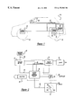
- FIG. 2 is a schematic of a charging system according to the present invention.
- an electric vehicle 10 having a plurality of electrical elements distributed therein.
- a traction battery 12 is positioned in the rear portion of the electric vehicle 10 , which electrically communicates with motor 14 to provide rotational energy to rear wheels 16 .
- Braking systems 18 are rotationally engaged to rear wheels 16 and front wheels 20 .
- braking systems 18 converts rotational energy from front wheels 20 and rear wheels 16 into electrical energy. This electrical energy is then transmitted to battery 12 for charging thereof.
- Controller 22 is mounted to a fixed surface within electric vehicle 10 and contains various elements as will be discussed. Input to controller 22 keyswitch 24 provides an input to controller 22 representative of whether vehicle 10 is in an on condition. As such, keyswitch 24 provides an electrical signal required to allow controller 22 to provide electrical energy to motor 14 for rotational energy of rear wheels 16 . Controller 22 provides an output to display 36 which indicates the operating conditions of vehicle 10 (as will be discussed). Display 36 provides these operating conditions to a vehicle driver seated within electric vehicle 10 .
- controller 22 contains a battery energy measuring device 26 and an offset 28 .
- controller 22 could contain the system as disclosed in U.S. Pat. No. 5,568,052, issued on Oct. 22, 1996 and assigned to the assignee of the present application.
- Traction battery 12 supplies a charging signal across bus 30 to battery energy measuring device 26 within controller 22 .
- This signal is representative of the electrical charge state of traction battery 12 .
- the specific battery parameters which result in the charge of traction battery 12 will be recognized by those of ordinary skill as including, without limitation, such parameters as temperature, state of charge, age, charging history, etc.
- the charging signal will also be indicative of other factors such as the variations between the parameters of individual cells in a multi-cell battery pack, including the presence of a bad cell in the battery pack.
- Motor controller 32 provides a conduit to supply electrical energy from traction battery 12 to motor 14 . To vary the energy supply to motor 14 , causing rotation of rear wheels 16 , motor controller 32 adjusts the voltage and current provided therefrom in response to controller 22 . Motor controller 22 provides this adjustment in response to the desires of the vehicle operator.
- Battery energy measuring device 26 reads the current provided by traction battery 12 to motor controller 22 . This information is provided by inductive load sensor 34 , which thereby provides an input to battery energy measuring device 26 representative of the instantaneous current draw from traction battery 12 . Battery energy measuring device 26 combines the signal received from inductive load sensor 34 and bus 30 and provides a charging signal to display 36 across bus 38 indicative of the available current of traction battery 12 .
- Display 36 is preferably an analogue display responsive to charging signal across bus 38 .
- the display 36 is set up to have a sweeping needle 40 which is able to sweep across a path beginning at ⁇ 10% and ending at a position of 100%. Between these two positions is located a plurality of segments dividing the display 36 into 10% increments.
- Keyswitch 24 provides an aperture at a first end for receiving a vehicle driver's key and provides an output to battery energy measuring device 26 at a second end.
- the output to battery energy measuring device 26 provides a signal representing whether keyswitch 24 is in an on or an off condition.
- keyswitch 24 is in an off condition
- needle 40 is at rest at the ⁇ 10% as shown on display 36 .
- motor controller 22 enables the flow of electricity from traction battery 12 to motor 14 .
- offset 28 is enabled by battery energy measuring device 26 , thereby providing an offset signal to display 36 .
- Display 36 receives this signal from offset 28 and repositions needle 40 a predetermined amount more toward the 100% mark than was provided by charging signal across bus 38 . Preferably, this amount positions needle 40 at the 0% mark. It is noted, however, that needle 40 can move any predefined amount and is not limited to that disclosed in the application. As a result, when keyswitch 24 is an on condition and vehicle 10 is at a standstill, thus no draw from traction battery 12 , needle 40 moves a predefined amount which notifies the vehicle operator that the vehicle is on. This movement is due to offset 28 . A vehicle operator thus associates display 36 with a tachometer in typical internal combustion engine driven vehicle.
- braking systems 18 transmits this braking force as electrical energy across wire 42 .
- the charge provided by braking system 18 exceeds the power drawn by motor 14 .
- the available energy to motor 14 is greater than when the vehicle 10 is at a standstill.
- battery energy measuring device 26 reads a voltage across bus 30 and a current from inductive load sensor 34 which corresponds to available energy from traction battery 12 exceeding normal. Battery energy measuring device 26 transmits a charging signal across bus 38 to display 36 which causes needle 40 to be pulled in a counterclockwise direction.
- offset 28 causes needle 40 to be positioned at 0% when keyswitch 24 is on and vehicle 10 is at a standstill, the charging signal provided across bus 38 causes needle 40 to be pulled towards ⁇ 10%. This provides indication to the vehicle driver that traction battery 12 is being charged and more energy than normal is available to motor 14 .
Abstract
Description
Claims (11)
Priority Applications (1)
| Application Number | Priority Date | Filing Date | Title |
|---|---|---|---|
| US09/298,238 US6175303B1 (en) | 1999-04-22 | 1999-04-22 | Electric vehicle torque-o-meter |
Applications Claiming Priority (1)
| Application Number | Priority Date | Filing Date | Title |
|---|---|---|---|
| US09/298,238 US6175303B1 (en) | 1999-04-22 | 1999-04-22 | Electric vehicle torque-o-meter |
Publications (1)
| Publication Number | Publication Date |
|---|---|
| US6175303B1 true US6175303B1 (en) | 2001-01-16 |
Family
ID=23149646
Family Applications (1)
| Application Number | Title | Priority Date | Filing Date |
|---|---|---|---|
| US09/298,238 Expired - Lifetime US6175303B1 (en) | 1999-04-22 | 1999-04-22 | Electric vehicle torque-o-meter |
Country Status (1)
| Country | Link |
|---|---|
| US (1) | US6175303B1 (en) |
Cited By (11)
| Publication number | Priority date | Publication date | Assignee | Title |
|---|---|---|---|---|
| US6480106B1 (en) | 2000-12-11 | 2002-11-12 | Ford Global Technologies, Inc. | Rate of consumption gauge with variable rate of consumption limits |
| US20040046525A1 (en) * | 2002-09-09 | 2004-03-11 | Ford Global Technologies, Inc. | Control strategy for an electric motor using real time predictions of motor capability based on thermal modeling and measurements |
| US20040178756A1 (en) * | 2003-03-10 | 2004-09-16 | Fu Zhenxing | Prediction of available torque and power from battery-powered traction motor |
| US20060098371A1 (en) * | 2004-11-08 | 2006-05-11 | Wambsganss Peter M | Temperature sensor for power supply |
| US20060098369A1 (en) * | 2004-11-08 | 2006-05-11 | Wambsganss Peter M | Microcontroller controlled power supply |
| US20060098358A1 (en) * | 2004-11-08 | 2006-05-11 | Wambsganss Peter M | Power supply configured to detect a power source |
| US20060267556A1 (en) * | 2005-05-17 | 2006-11-30 | Milwaukee Electric Tool Corporation | Power tool, battery, charger and method of operating the same |
| US20070254538A1 (en) * | 2005-11-30 | 2007-11-01 | Autotether, Inc. | Safety shut-off device for vehicle having a rotary on-off switch |
| US20070256620A1 (en) * | 2005-11-30 | 2007-11-08 | Autotether, Inc. | Sailboat safety system for a person falling overboard |
| US20090031865A1 (en) * | 2005-05-17 | 2009-02-05 | Alberti Daniel J | Power tool, battery, charger and method of operating the same |
| CN111086415A (en) * | 2019-12-20 | 2020-05-01 | 一汽解放汽车有限公司 | Battery charging management method, device, vehicle and storage medium |
Citations (13)
| Publication number | Priority date | Publication date | Assignee | Title |
|---|---|---|---|---|
| US4333149A (en) * | 1980-03-06 | 1982-06-01 | General Electric Company | Microprocessor-based state of charge gauge for secondary batteries |
| US4659977A (en) | 1984-10-01 | 1987-04-21 | Chrysler Motors Corporation | Microcomputer controlled electronic alternator for vehicles |
| US4888637A (en) | 1988-01-15 | 1989-12-19 | Chrysler Motors Corporation | Multiple semiconductor heat sink/mounting assembly |
| US4899256A (en) | 1988-06-01 | 1990-02-06 | Chrysler Motors Corporation | Power module |
| US5371412A (en) * | 1993-02-05 | 1994-12-06 | Toyota Jidosha Kabushiki Kaisha | Control method and apparatus of engine for driving generator |
| US5392643A (en) | 1993-11-22 | 1995-02-28 | Chrysler Corporation | Oxygen heater sensor diagnostic routine |
| US5561380A (en) | 1995-05-08 | 1996-10-01 | Chrysler Corporation | Fault detection system for electric automobile traction system having floating ground |
| US5568052A (en) | 1994-12-09 | 1996-10-22 | Chrysler Corporation | Performance monitor for electric vehicle |
| US5612608A (en) * | 1993-12-28 | 1997-03-18 | Honda Giken Kogyo Kabushiki Kaisha | Apparatus for displaying residual capacity of battery for use on electric vehicle |
| US5619417A (en) | 1994-11-23 | 1997-04-08 | Chrysler Corporation | Battery monitoring system for an electric vehicle |
| US5646534A (en) | 1995-01-06 | 1997-07-08 | Chrysler Corporation | Battery monitor for electric vehicles |
| US5698983A (en) * | 1995-04-07 | 1997-12-16 | Yazaki Corporation | Method and apparatus for measuring and displaying remaining battery capacity as a two dimensional dot curve |
| US5864106A (en) | 1997-01-07 | 1999-01-26 | Chrysler Corporation | Battery disconnect switch for electric vehicle |
-
1999
- 1999-04-22 US US09/298,238 patent/US6175303B1/en not_active Expired - Lifetime
Patent Citations (14)
| Publication number | Priority date | Publication date | Assignee | Title |
|---|---|---|---|---|
| US4333149A (en) * | 1980-03-06 | 1982-06-01 | General Electric Company | Microprocessor-based state of charge gauge for secondary batteries |
| US4659977A (en) | 1984-10-01 | 1987-04-21 | Chrysler Motors Corporation | Microcomputer controlled electronic alternator for vehicles |
| US4888637A (en) | 1988-01-15 | 1989-12-19 | Chrysler Motors Corporation | Multiple semiconductor heat sink/mounting assembly |
| US4899256A (en) | 1988-06-01 | 1990-02-06 | Chrysler Motors Corporation | Power module |
| US5371412A (en) * | 1993-02-05 | 1994-12-06 | Toyota Jidosha Kabushiki Kaisha | Control method and apparatus of engine for driving generator |
| US5392643A (en) | 1993-11-22 | 1995-02-28 | Chrysler Corporation | Oxygen heater sensor diagnostic routine |
| US5612608A (en) * | 1993-12-28 | 1997-03-18 | Honda Giken Kogyo Kabushiki Kaisha | Apparatus for displaying residual capacity of battery for use on electric vehicle |
| US5619417A (en) | 1994-11-23 | 1997-04-08 | Chrysler Corporation | Battery monitoring system for an electric vehicle |
| US5568052A (en) | 1994-12-09 | 1996-10-22 | Chrysler Corporation | Performance monitor for electric vehicle |
| US5646534A (en) | 1995-01-06 | 1997-07-08 | Chrysler Corporation | Battery monitor for electric vehicles |
| US5808469A (en) | 1995-01-06 | 1998-09-15 | Chrysler Corporation | Battery monitor for electric vehicles |
| US5698983A (en) * | 1995-04-07 | 1997-12-16 | Yazaki Corporation | Method and apparatus for measuring and displaying remaining battery capacity as a two dimensional dot curve |
| US5561380A (en) | 1995-05-08 | 1996-10-01 | Chrysler Corporation | Fault detection system for electric automobile traction system having floating ground |
| US5864106A (en) | 1997-01-07 | 1999-01-26 | Chrysler Corporation | Battery disconnect switch for electric vehicle |
Cited By (19)
| Publication number | Priority date | Publication date | Assignee | Title |
|---|---|---|---|---|
| US6480106B1 (en) | 2000-12-11 | 2002-11-12 | Ford Global Technologies, Inc. | Rate of consumption gauge with variable rate of consumption limits |
| US20040046525A1 (en) * | 2002-09-09 | 2004-03-11 | Ford Global Technologies, Inc. | Control strategy for an electric motor using real time predictions of motor capability based on thermal modeling and measurements |
| US6861820B2 (en) | 2002-09-09 | 2005-03-01 | Ford Global Technologies, Llc | Control strategy for an electric motor using real time predictions of motor capability based on thermal modeling and measurements |
| US20040178756A1 (en) * | 2003-03-10 | 2004-09-16 | Fu Zhenxing | Prediction of available torque and power from battery-powered traction motor |
| US6831429B2 (en) | 2003-03-10 | 2004-12-14 | Visteon Global Technologies, Inc. | Prediction of available torque and power from battery-powered traction motor |
| US7408132B2 (en) | 2004-11-08 | 2008-08-05 | Rrc Power Solutions Gmbh | Temperature sensor for power supply |
| US20060098371A1 (en) * | 2004-11-08 | 2006-05-11 | Wambsganss Peter M | Temperature sensor for power supply |
| US20060098369A1 (en) * | 2004-11-08 | 2006-05-11 | Wambsganss Peter M | Microcontroller controlled power supply |
| US20060098358A1 (en) * | 2004-11-08 | 2006-05-11 | Wambsganss Peter M | Power supply configured to detect a power source |
| US20060267556A1 (en) * | 2005-05-17 | 2006-11-30 | Milwaukee Electric Tool Corporation | Power tool, battery, charger and method of operating the same |
| US20090031865A1 (en) * | 2005-05-17 | 2009-02-05 | Alberti Daniel J | Power tool, battery, charger and method of operating the same |
| US20090102420A1 (en) * | 2005-05-17 | 2009-04-23 | Nancy Uehlein-Proctor | Power tool, battery, charger and method of operating the same |
| US7649337B2 (en) * | 2005-05-17 | 2010-01-19 | Milwaukee Electric Tool Corporation | Power tool including a fuel gauge and method of operating the same |
| US7814816B2 (en) | 2005-05-17 | 2010-10-19 | Milwaukee Electric Tool Corporation | Power tool, battery, charger and method of operating the same |
| US7932695B2 (en) | 2005-05-17 | 2011-04-26 | Milwaukee Electric Tool Corporation | Power tool, battery, charger and method of operating the same |
| US20070256620A1 (en) * | 2005-11-30 | 2007-11-08 | Autotether, Inc. | Sailboat safety system for a person falling overboard |
| US20070254538A1 (en) * | 2005-11-30 | 2007-11-01 | Autotether, Inc. | Safety shut-off device for vehicle having a rotary on-off switch |
| CN111086415A (en) * | 2019-12-20 | 2020-05-01 | 一汽解放汽车有限公司 | Battery charging management method, device, vehicle and storage medium |
| CN111086415B (en) * | 2019-12-20 | 2021-11-23 | 一汽解放汽车有限公司 | Battery charging management method, device, vehicle and storage medium |
Similar Documents
| Publication | Publication Date | Title |
|---|---|---|
| US5929609A (en) | Vehicular power management system and method | |
| EP1020319B1 (en) | Assist device for use in electric vehicle | |
| US6435294B1 (en) | Control device for hybrid vehicle | |
| US5898282A (en) | Control system for a hybrid vehicle | |
| CN103079897B (en) | Control device for vehicle and control method for vehicle | |
| CN100453359C (en) | Power output apparatus, method of controlling power output apparatus, and automobile with power output apparatus mounted thereon | |
| US6917180B2 (en) | Methods and apparatus for controlling electric vehicle battery charger and motor using a single unitary controller | |
| EP2168826B1 (en) | Hybrid vehicle | |
| US6175303B1 (en) | Electric vehicle torque-o-meter | |
| US5670830A (en) | Fuel use limiter-equipped hybrid electric car | |
| US9855958B2 (en) | Vehicle that switches between displaying fuel efficiency on a display device and displaying electricity efficiency on the display device based on engine use history when a selected running mode is a charge depleting mode | |
| US8190325B2 (en) | System and method for displaying an instantaneous fuel economy of a vehicle | |
| EP2204872A1 (en) | Secondary battery control system, electric vehicle mounting the control system, and secondary battery control method | |
| JP2001078306A (en) | Controller of hybrid vehicle | |
| US10946761B2 (en) | Battery management device, vehicle having the same, and method for controlling the vehicle | |
| US10427537B2 (en) | Vehicle power supply control | |
| EP0796484B1 (en) | Performance monitor for electric vehicle | |
| CN103326648A (en) | Power generation control device | |
| KR100844729B1 (en) | Device and method for LDC control of HEV | |
| JP2017109633A (en) | Electric-vehicular control apparatus | |
| JP2004271410A (en) | Battery controlling apparatus for electric vehicle | |
| JP2000166105A (en) | Charged state controller for battery | |
| CN106004859B (en) | Vehicle performance preload enabler | |
| KR101611285B1 (en) | electric vehicle and control method thereof | |
| KR20120060068A (en) | Apparatus for estimation motor speed of hybrid vehicle and method thereof |
Legal Events
| Date | Code | Title | Description |
|---|---|---|---|
| AS | Assignment |
Owner name: DAIMLERCHRYSLER CORPORATION, MICHIGAN Free format text: ASSIGNMENT OF ASSIGNORS INTEREST;ASSIGNORS:HANSEN, ERIK J.;THEOFANOPOULOS, JOHN;REEL/FRAME:009991/0470 Effective date: 19990413 |
|
| STCF | Information on status: patent grant |
Free format text: PATENTED CASE |
|
| FPAY | Fee payment |
Year of fee payment: 4 |
|
| AS | Assignment |
Owner name: WILMINGTON TRUST COMPANY, DELAWARE Free format text: GRANT OF SECURITY INTEREST IN PATENT RIGHTS - FIRST PRIORITY;ASSIGNOR:CHRYSLER LLC;REEL/FRAME:019773/0001 Effective date: 20070803 Owner name: WILMINGTON TRUST COMPANY,DELAWARE Free format text: GRANT OF SECURITY INTEREST IN PATENT RIGHTS - FIRST PRIORITY;ASSIGNOR:CHRYSLER LLC;REEL/FRAME:019773/0001 Effective date: 20070803 |
|
| AS | Assignment |
Owner name: WILMINGTON TRUST COMPANY, DELAWARE Free format text: GRANT OF SECURITY INTEREST IN PATENT RIGHTS - SECOND PRIORITY;ASSIGNOR:CHRYSLER LLC;REEL/FRAME:019767/0810 Effective date: 20070803 Owner name: WILMINGTON TRUST COMPANY,DELAWARE Free format text: GRANT OF SECURITY INTEREST IN PATENT RIGHTS - SECOND PRIORITY;ASSIGNOR:CHRYSLER LLC;REEL/FRAME:019767/0810 Effective date: 20070803 |
|
| FPAY | Fee payment |
Year of fee payment: 8 |
|
| AS | Assignment |
Owner name: DAIMLERCHRYSLER COMPANY LLC, MICHIGAN Free format text: CHANGE OF NAME;ASSIGNOR:DAIMLERCHRYSLER CORPORATION;REEL/FRAME:021779/0793 Effective date: 20070329 |
|
| AS | Assignment |
Owner name: CHRYSLER LLC, MICHIGAN Free format text: CHANGE OF NAME;ASSIGNOR:DAIMLERCHRYSLER COMPANY LLC;REEL/FRAME:021826/0001 Effective date: 20070727 |
|
| AS | Assignment |
Owner name: US DEPARTMENT OF THE TREASURY, DISTRICT OF COLUMBI Free format text: GRANT OF SECURITY INTEREST IN PATENT RIGHTS - THIR;ASSIGNOR:CHRYSLER LLC;REEL/FRAME:022259/0188 Effective date: 20090102 Owner name: US DEPARTMENT OF THE TREASURY,DISTRICT OF COLUMBIA Free format text: GRANT OF SECURITY INTEREST IN PATENT RIGHTS - THIR;ASSIGNOR:CHRYSLER LLC;REEL/FRAME:022259/0188 Effective date: 20090102 |
|
| AS | Assignment |
Owner name: CHRYSLER LLC, MICHIGAN Free format text: RELEASE BY SECURED PARTY;ASSIGNOR:US DEPARTMENT OF THE TREASURY;REEL/FRAME:022910/0273 Effective date: 20090608 |
|
| AS | Assignment |
Owner name: CHRYSLER LLC, MICHIGAN Free format text: RELEASE OF SECURITY INTEREST IN PATENT RIGHTS - FIRST PRIORITY;ASSIGNOR:WILMINGTON TRUST COMPANY;REEL/FRAME:022910/0498 Effective date: 20090604 Owner name: CHRYSLER LLC, MICHIGAN Free format text: RELEASE OF SECURITY INTEREST IN PATENT RIGHTS - SECOND PRIORITY;ASSIGNOR:WILMINGTON TRUST COMPANY;REEL/FRAME:022910/0740 Effective date: 20090604 Owner name: NEW CARCO ACQUISITION LLC, MICHIGAN Free format text: ASSIGNMENT OF ASSIGNORS INTEREST;ASSIGNOR:CHRYSLER LLC;REEL/FRAME:022915/0001 Effective date: 20090610 Owner name: THE UNITED STATES DEPARTMENT OF THE TREASURY, DIST Free format text: SECURITY AGREEMENT;ASSIGNOR:NEW CARCO ACQUISITION LLC;REEL/FRAME:022915/0489 Effective date: 20090610 Owner name: CHRYSLER LLC,MICHIGAN Free format text: RELEASE OF SECURITY INTEREST IN PATENT RIGHTS - FIRST PRIORITY;ASSIGNOR:WILMINGTON TRUST COMPANY;REEL/FRAME:022910/0498 Effective date: 20090604 Owner name: CHRYSLER LLC,MICHIGAN Free format text: RELEASE OF SECURITY INTEREST IN PATENT RIGHTS - SECOND PRIORITY;ASSIGNOR:WILMINGTON TRUST COMPANY;REEL/FRAME:022910/0740 Effective date: 20090604 Owner name: NEW CARCO ACQUISITION LLC,MICHIGAN Free format text: ASSIGNMENT OF ASSIGNORS INTEREST;ASSIGNOR:CHRYSLER LLC;REEL/FRAME:022915/0001 Effective date: 20090610 Owner name: THE UNITED STATES DEPARTMENT OF THE TREASURY,DISTR Free format text: SECURITY AGREEMENT;ASSIGNOR:NEW CARCO ACQUISITION LLC;REEL/FRAME:022915/0489 Effective date: 20090610 |
|
| AS | Assignment |
Owner name: CHRYSLER GROUP LLC, MICHIGAN Free format text: CHANGE OF NAME;ASSIGNOR:NEW CARCO ACQUISITION LLC;REEL/FRAME:022919/0126 Effective date: 20090610 Owner name: CHRYSLER GROUP LLC,MICHIGAN Free format text: CHANGE OF NAME;ASSIGNOR:NEW CARCO ACQUISITION LLC;REEL/FRAME:022919/0126 Effective date: 20090610 |
|
| AS | Assignment |
Owner name: CHRYSLER GROUP LLC, MICHIGAN Free format text: RELEASE BY SECURED PARTY;ASSIGNOR:THE UNITED STATES DEPARTMENT OF THE TREASURY;REEL/FRAME:026343/0298 Effective date: 20110524 Owner name: CHRYSLER GROUP GLOBAL ELECTRIC MOTORCARS LLC, NORT Free format text: RELEASE BY SECURED PARTY;ASSIGNOR:THE UNITED STATES DEPARTMENT OF THE TREASURY;REEL/FRAME:026343/0298 Effective date: 20110524 |
|
| AS | Assignment |
Owner name: CITIBANK, N.A., NEW YORK Free format text: SECURITY AGREEMENT;ASSIGNOR:CHRYSLER GROUP LLC;REEL/FRAME:026404/0123 Effective date: 20110524 |
|
| AS | Assignment |
Owner name: CITIBANK, N.A., NEW YORK Free format text: SECURITY AGREEMENT;ASSIGNOR:CHRYSLER GROUP LLC;REEL/FRAME:026435/0652 Effective date: 20110524 |
|
| FPAY | Fee payment |
Year of fee payment: 12 |
|
| AS | Assignment |
Owner name: JPMORGAN CHASE BANK, N.A., ILLINOIS Free format text: SECURITY AGREEMENT;ASSIGNOR:CHRYSLER GROUP LLC;REEL/FRAME:032384/0640 Effective date: 20140207 |
|
| AS | Assignment |
Owner name: FCA US LLC, MICHIGAN Free format text: CHANGE OF NAME;ASSIGNOR:CHRYSLER GROUP LLC;REEL/FRAME:035553/0356 Effective date: 20141203 |
|
| AS | Assignment |
Owner name: FCA US LLC, FORMERLY KNOWN AS CHRYSLER GROUP LLC, Free format text: RELEASE OF SECURITY INTEREST RELEASING SECOND-LIEN SECURITY INTEREST PREVIOUSLY RECORDED AT REEL 026426 AND FRAME 0644, REEL 026435 AND FRAME 0652, AND REEL 032384 AND FRAME 0591;ASSIGNOR:CITIBANK, N.A.;REEL/FRAME:037784/0001 Effective date: 20151221 |
|
| AS | Assignment |
Owner name: FCA US LLC (FORMERLY KNOWN AS CHRYSLER GROUP LLC), Free format text: RELEASE BY SECURED PARTY;ASSIGNOR:CITIBANK, N.A.;REEL/FRAME:042885/0255 Effective date: 20170224 |
|
| AS | Assignment |
Owner name: FCA US LLC (FORMERLY KNOWN AS CHRYSLER GROUP LLC), Free format text: RELEASE BY SECURED PARTY;ASSIGNOR:JPMORGAN CHASE BANK, N.A.;REEL/FRAME:048177/0356 Effective date: 20181113 |