US6177740B1 - Integrated motor and motor drive unit - Google Patents
Integrated motor and motor drive unit Download PDFInfo
- Publication number
- US6177740B1 US6177740B1 US09/240,158 US24015899A US6177740B1 US 6177740 B1 US6177740 B1 US 6177740B1 US 24015899 A US24015899 A US 24015899A US 6177740 B1 US6177740 B1 US 6177740B1
- Authority
- US
- United States
- Prior art keywords
- motor
- power distribution
- case
- drive unit
- distribution bus
- Prior art date
- Legal status (The legal status is an assumption and is not a legal conclusion. Google has not performed a legal analysis and makes no representation as to the accuracy of the status listed.)
- Expired - Lifetime
Links
Images

Classifications
-
- H—ELECTRICITY
- H02—GENERATION; CONVERSION OR DISTRIBUTION OF ELECTRIC POWER
- H02K—DYNAMO-ELECTRIC MACHINES
- H02K5/00—Casings; Enclosures; Supports
- H02K5/04—Casings or enclosures characterised by the shape, form or construction thereof
- H02K5/22—Auxiliary parts of casings not covered by groups H02K5/06-H02K5/20, e.g. shaped to form connection boxes or terminal boxes
- H02K5/225—Terminal boxes or connection arrangements
-
- H—ELECTRICITY
- H02—GENERATION; CONVERSION OR DISTRIBUTION OF ELECTRIC POWER
- H02K—DYNAMO-ELECTRIC MACHINES
- H02K11/00—Structural association of dynamo-electric machines with electric components or with devices for shielding, monitoring or protection
- H02K11/30—Structural association with control circuits or drive circuits
- H02K11/33—Drive circuits, e.g. power electronics
-
- H—ELECTRICITY
- H02—GENERATION; CONVERSION OR DISTRIBUTION OF ELECTRIC POWER
- H02K—DYNAMO-ELECTRIC MACHINES
- H02K29/00—Motors or generators having non-mechanical commutating devices, e.g. discharge tubes or semiconductor devices
- H02K29/06—Motors or generators having non-mechanical commutating devices, e.g. discharge tubes or semiconductor devices with position sensing devices
- H02K29/08—Motors or generators having non-mechanical commutating devices, e.g. discharge tubes or semiconductor devices with position sensing devices using magnetic effect devices, e.g. Hall-plates, magneto-resistors
-
- H—ELECTRICITY
- H02—GENERATION; CONVERSION OR DISTRIBUTION OF ELECTRIC POWER
- H02K—DYNAMO-ELECTRIC MACHINES
- H02K2203/00—Specific aspects not provided for in the other groups of this subclass relating to the windings
- H02K2203/03—Machines characterised by the wiring boards, i.e. printed circuit boards or similar structures for connecting the winding terminations
-
- H—ELECTRICITY
- H02—GENERATION; CONVERSION OR DISTRIBUTION OF ELECTRIC POWER
- H02K—DYNAMO-ELECTRIC MACHINES
- H02K2211/00—Specific aspects not provided for in the other groups of this subclass relating to measuring or protective devices or electric components
- H02K2211/03—Machines characterised by circuit boards, e.g. pcb
-
- H—ELECTRICITY
- H02—GENERATION; CONVERSION OR DISTRIBUTION OF ELECTRIC POWER
- H02K—DYNAMO-ELECTRIC MACHINES
- H02K3/00—Details of windings
- H02K3/46—Fastening of windings on the stator or rotor structure
- H02K3/50—Fastening of winding heads, equalising connectors, or connections thereto
Definitions
- the present invention relates generally to electrical motors. More specifically, the present invention relates to an integrated motor and motor drive unit.
- Electric motors are used in many industries. On automobiles, motors are used in various locations. For example, motors may be used to drive a pump.
- these motors generally comprise two main components; a motor assembly and a drive assembly.
- the motor assembly includes the actual rotating motor.
- the drive assembly includes the drive electronics for controlling the operation of the motor.
- the motor and the drive assembly are two separate components connected by an external cable assembly. There are several disadvantages to a separate drive assembly and motor assembly.
- An external cable assembly increases electrical resistance for the system, and may act as an antenna which may both receive and radiate unwanted electromagnetic interference.
- the FCC has regulated the electromagnetic radiation emitted from a motor.
- a more expensive shielded wire must be used if electromagnetic interference exceeds the FCC regulation.
- Another disadvantage to providing a separate drive assembly and motor assembly is the integration of the two separate units into the finished product. Having two separate assemblies increases the space required for a motor and drive unit. Also, the assembly complexity for mounting two components is relatively high.
- motors For automotive applications, motors use a relatively low voltage and draw high currents. This causes the motors to dissipate more power. Some industrial integrated drive motors operate at 110 volts. The high voltage motors draw little current and dissipate small amounts of power. Because of the low power dissipation, organic-based circuit boards for power distribution may be used in such applications. However, in low voltage automotive applications, organic-based circuit boards cannot be used.
- a motor and motor drive unit assembly includes a motor assembly having a housing and a motor rotatably coupled within the housing.
- a power distribution bus is coupled to the housing.
- the power distribution bus is coupled to an end cap of the motor.
- a plurality of semiconductor switches are coupled to the power distribution bus.
- the motor and drive assembly further includes a drive assembly having a case or housing coupled to the power distribution bus.
- the case is preferably electrically isolated from, and is in thermal communication with, the power distribution bus.
- the case or housing has a plurality of openings therethrough.
- An interconnect circuit board is disposed within the case and is electrically coupled to the power distribution bus through the plurality of openings.
- a system control board is disposed within the case and is electrically coupled to the interconnect board.
- One advantage of the invention is the high heat dissipation capabilities. Because the power distribution bus is located between the case and the motor housing, both the motor housing and the case may act as a heat sink. Another advantage of the invention is that the semiconductor switches are coupled directly on the motor eliminating interconnecting wires. Another advantage of the invention is that the shaft position sensors may be mounted directly to the system control board within the case which results in a lower cost assembly.
- the present invention may be used for more than just a motor.
- teachings of the present invention may be applied to a power supply or other power intensive application.
- a power distribution bus such as that described above is coupled between a first thermally conductive member and a second thermally conductive member.
- the power distribution bus has a plurality of semiconductor switches mounted thereto.
- the first and second thermally conductive members may, for example, be a heat sink, a circuit board housing for housing electronic control circuitry or other type of housing.
- the power distribution bus is electrically isolated from the first thermally conductive member and the second thermally conductive member.
- the power distribution bus is thermally coupled to the first thermally conductive member and the second thermally conductive member to allow heat to be dissipated from the power distribution bus through the first thermally conductive member and the second thermally conductive member.
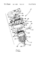
- FIG. 1 is an exploded view of a motor and motor drive assembly according to the present invention.
- FIG. 2 is a partial cutaway view of a motor and motor drive assembly of FIG. 1 .
- a motor and drive assembly unit 10 has a motor assembly 12 and a drive assembly 14 as shown in FIGS. 1 and 2.
- a power distribution bus 16 is coupled between the motor assembly 12 and drive assembly 14 .
- Motor assembly 12 has a motor housing 18 that is generally comprised of a cylindrical outer sleeve 20 and an end cap 22 . Cylindrical outer sleeve 20 may have cooling fins 24 disposed thereon. Housing 18 is preferably thermally conductive providing heat dissipation for motor assembly 12 .
- Housing 18 encloses a motor 26 .
- Motor 26 has a shaft 28 and a rotor 30 coupled to shaft 28 .
- a stator 32 that is comprised of a plurality of windings 34 .
- Bearings 36 are coupled to shaft 28 to position shaft 28 within housing 18 .
- Windings 34 have winding terminations 38 that extend through end cap 22 of housing 18 .
- winding terminations 38 are used to couple power to windings 34 .
- winding terminations 38 and threaded fasteners may also be used to help secure motor and drive unit assembly 10 together.
- Case 40 is preferably formed from a thermally conductive material to allow heat to be dissipated from the motor and the control circuitry. Case 40 may also have a generally cylindrically shaped recess 52 on the exterior thereof. Recess 52 is sized to receive housing 18 and power distribution bus 16 . Case 40 may also have an interior recess 54 to accommodate electronic components of interconnect board 46 . For example, interior recess 54 may be sized to accommodate capacitors 56 .
- Recess 52 may have a plurality of apertures for interconnecting with the power distribution bus 16 and with the motor and, more specifically, winding terminations 38 and shaft 28 .
- Case 40 may, therefore, have a shaft aperture 58 , winding apertures 60 , and switch apertures 62 .
- Control board 48 may have a plurality of position sensors 64 coupled thereto.
- Position sensors 64 may, for example, be of the Hall effect type. However, various types of position sensors may be used. Position sensors 64 in combination with encoder wheel 50 provide feedback to the remaining circuitry on control board 48 and interconnect board 46 as to the position of the shaft 28 .
- a connector 66 may be coupled to case 40 for providing external power to the motor and drive unit assembly 10 .
- Connector 66 has a copper strip 68 that extends between connector 66 and interconnect board 46 . From the interconnect board 46 , power is distributed to the control circuitry and to motor windings 34 .
- Power distribution bus 16 is generally formed of an electrically and thermally conductive material such as copper. Power distribution bus 16 is coupled between end cap 22 and case 40 . Because case 40 and end cap 22 are preferably thermally conductive, they are also most likely metallic and thus electrically conductive. Consequently, some means for electrically isolating power distribution bus 16 , case 40 , and end cap 22 should be provided. One means for electrically isolating case 40 and end cap 22 is placing a coupling material such as a non-electrically conductive film therebetween. A first layer of film 70 and a second layer of film 72 are provided between power distribution bus 16 and end cap 22 , and between power distribution bus 16 and case 40 , respectively. Films 70 , 72 are preferably sized to cover the area of power distribution bus 16 .
- films 70 , 72 may be provided in films 70 , 72 to allow winding terminations 38 and shaft 28 to pass therethrough.
- Films 70 , 72 are also thermally conductive so that any heat in power distribution bus 16 is coupled to case 40 and end cap 22 and ultimately to housing 18 .
- Suitable materials for films 70 , 72 include but are not limited to mica, epoxy, thermal grease, or a double-sided tape.
- Power distribution bus 16 has a plurality of semiconductor switches 76 mounted thereto.
- Semiconductor switches 76 may, for example, be MOSFETS, switching diodes or other switching devices commonly known in the art.
- Semiconductor switches 76 ultimately control the power supplied to windings 34 and ultimately control the operating parameters of the motor such as motor speed.
- Power distribution bus 16 has a plurality of tabs 78 integrally formed with power distribution bus 16 .
- Tabs 78 in the preferred embodiment are formed coextensively with power distribution bus 16 and extend in an axial direction through case 40 and into cavity 44 .
- Tabs 78 are formed adjacent to a respective winding termination 38 which also extends into cavity 44 .
- Tabs 78 and winding terminations 38 are electrically coupled by crimping, welding, soldering, or other coupling means. The coupled tabs 78 and winding terminations 38 may be electrically coupled to interconnect board 46 and control board 48 .
- motor assembly 12 is assembled in a conventional manner. Winding terminations 38 , however, extend through end cap 22 . Also, shaft 28 extends through end cap 22 . Film 70 is then positioned on end cap 22 or coupled to power distribution bus 16 so that power distribution bus 16 is electrically isolated and thermally coupled to housing 18 . Case 40 is positioned so that recess 52 fits over cylindrical outer sleeve 20 and power distribution bus 16 . Tabs 78 , winding terminations 38 , and shaft 28 will then extend through their respective apertures and into cavity 44 . Winding terminations 38 and tabs 78 are electrically coupled together and to interconnect board 46 . Control board 48 is also coupled to interconnect board 46 within cavity 44 .
- the encoder wheel 50 is then coupled to shaft 28 adjacent to position sensors 64 .
- the motor and drive unit assembly may be held together by threaded fasteners (not shown).
- Cover 42 is coupled to case 40 and is used to enclose cavity 44 , thus the complete motor and drive unit assembly 10 is coupled together.
- heat is generated by semiconductor switches 76 . Because of the thermal coupling between housing 18 and case 40 , heat is transferred to case 40 and end cap 22 . The heat from end cap 22 is coupled to cylindrical outer sleeve 20 and ultimately to cooling fins 24 . Of course, each of these components dissipates heat.
- case 40 could be the case of a power supply while housing 18 could be the heat sink of a power supply.
- Power distribution bus 16 may be coupled to case 40 and the housing 18 in a similar manner to that described above so that heat may be dissipated on both sides of power distribution bus 16 .
Abstract
Description
Claims (12)
Priority Applications (1)
| Application Number | Priority Date | Filing Date | Title |
|---|---|---|---|
| US09/240,158 US6177740B1 (en) | 1999-01-29 | 1999-01-29 | Integrated motor and motor drive unit |
Applications Claiming Priority (1)
| Application Number | Priority Date | Filing Date | Title |
|---|---|---|---|
| US09/240,158 US6177740B1 (en) | 1999-01-29 | 1999-01-29 | Integrated motor and motor drive unit |
Publications (1)
| Publication Number | Publication Date |
|---|---|
| US6177740B1 true US6177740B1 (en) | 2001-01-23 |
Family
ID=22905353
Family Applications (1)
| Application Number | Title | Priority Date | Filing Date |
|---|---|---|---|
| US09/240,158 Expired - Lifetime US6177740B1 (en) | 1999-01-29 | 1999-01-29 | Integrated motor and motor drive unit |
Country Status (1)
| Country | Link |
|---|---|
| US (1) | US6177740B1 (en) |
Cited By (42)
| Publication number | Priority date | Publication date | Assignee | Title |
|---|---|---|---|---|
| US20030096854A1 (en) * | 2002-06-12 | 2003-05-22 | Ho-Shen Lin | Substituted tricyclics |
| US20030094920A1 (en) * | 2001-11-20 | 2003-05-22 | Mitsubishi Denki Kabushiki Kaisha | Inverter-equipped motor |
| US6570284B1 (en) | 2001-12-11 | 2003-05-27 | Black & Decker Inc. | Brushless motor having double insulation |
| US6661140B2 (en) | 2001-12-11 | 2003-12-09 | Black & Decker Inc. | Brushless motor having housing enabling alignment of stator and sensor |
| US20040027014A1 (en) * | 2001-04-20 | 2004-02-12 | Thomas Weigold | Electronically commutated direct current motor |
| US20040037719A1 (en) * | 2002-01-30 | 2004-02-26 | Calsonic Kansei Corporation | Canned pump |
| US6720689B2 (en) | 2001-12-11 | 2004-04-13 | Black & Decker Inc. | Brushless motor having capacitors mounted on sidewall of motor housing |
| US20060002054A1 (en) * | 2004-07-02 | 2006-01-05 | Visteon Global Technologies, Inc. | Electric machine with integrated electronics in a circular/closed-loop arrangement |
| US20060003604A1 (en) * | 2001-03-15 | 2006-01-05 | Ltn Servotechnik Gmbh: | Slip ring unit with a printed circuit board |
| US20060066155A1 (en) * | 2004-09-25 | 2006-03-30 | Kaiser Matin | Method and system for cooling a motor or motor enclosure |
| US20060166519A1 (en) * | 2005-01-25 | 2006-07-27 | Borgwarner Inc. | Control and interconnection system for an apparatus |
| US20060175913A1 (en) * | 2002-02-04 | 2006-08-10 | Hempe David A | Power tools with switched reluctance motor |
| US20070267926A1 (en) * | 2006-01-06 | 2007-11-22 | International Rectifier Corp. | Mechatronic integration of motor drive and E-machine, especially smart-E-motor |
| US20080018182A1 (en) * | 2006-07-13 | 2008-01-24 | Diehl Ako Stifting & Co. Kg | Drive apparatus for a washing machine |
| US20090272854A1 (en) * | 2007-04-10 | 2009-11-05 | Violett Robert S | Electric propulsion system useful in jet-type model airplanes and uavs |
| JP2010263728A (en) * | 2009-05-08 | 2010-11-18 | Asmo Co Ltd | Motor |
| US20100320880A1 (en) * | 2007-03-09 | 2010-12-23 | Panasonic Corporation | Brushless motor |
| US20110068661A1 (en) * | 2009-09-23 | 2011-03-24 | Clendenen David A | Motor controller and method for assembling the same |
| WO2011069545A1 (en) * | 2009-12-10 | 2011-06-16 | Siemens Aktiengesellschaft | Condition monitoring system of a motor |
| US20110241454A1 (en) * | 2008-09-19 | 2011-10-06 | Grundfos Management A/S | Pump assembly |
| CN102244423A (en) * | 2010-05-13 | 2011-11-16 | 德昌电机(深圳)有限公司 | Motor |
| WO2013117619A2 (en) | 2012-02-09 | 2013-08-15 | Bernecker + Rainer Industrie-Elektronik Ges.M.B.H | Servomotor |
| US20140077630A1 (en) * | 2012-09-14 | 2014-03-20 | Rockwell Automation Technologies, Inc. | Heatsink design with thermal insulator to reduce encoder temperature for mp motor |
| CN104011980A (en) * | 2011-12-23 | 2014-08-27 | 格兰富控股联合股份公司 | Electric drive motor |
| CN104136781A (en) * | 2011-12-23 | 2014-11-05 | 格兰富控股联合股份公司 | Electric motor |
| CN104682781A (en) * | 2013-11-29 | 2015-06-03 | 株式会社电装 | Driver Device |
| US20150333589A1 (en) * | 2012-12-18 | 2015-11-19 | Spal Automotive S.R.L. | Electrical machine |
| US20160211727A1 (en) * | 2015-01-20 | 2016-07-21 | Zf Friedrichshafen Ag | Motor assembly |
| US20160380522A1 (en) * | 2011-08-10 | 2016-12-29 | Lg Innotek Co., Ltd. | Stator and EPS Motor Having the Same |
| US20170353082A1 (en) * | 2016-06-01 | 2017-12-07 | Hitachi Automotive Systems, Ltd. | Electric drive apparatus, and electric power steering apparatus |
| US20180003185A1 (en) * | 2013-11-13 | 2018-01-04 | Reza Afshar | Dual speed motor controller and method of operation |
| US10135321B2 (en) | 2012-09-14 | 2018-11-20 | Rockwell Automation Technologies, Inc. | Heatsink design with thermal insulator to reduce encoder temperature |
| US10236742B2 (en) | 2014-11-25 | 2019-03-19 | Black & Decker Inc. | Brushless motor for a power tool |
| US10328567B2 (en) | 2015-10-14 | 2019-06-25 | Black & Decker Inc. | Brushless motor system for power tools |
| US10693347B2 (en) | 2018-06-22 | 2020-06-23 | Chicony Power Technology Co., Ltd. | Motor device and heat dissipation device |
| US10855146B2 (en) | 2016-03-11 | 2020-12-01 | Itt Manufacturing Enterprises Llc | Motor drive unit |
| US10958183B2 (en) | 2016-12-05 | 2021-03-23 | Itt Manufacturing Enterprises Llc | Matrix converter control using predicted output current |
| WO2021147321A1 (en) * | 2020-01-22 | 2021-07-29 | 中山大洋电机股份有限公司 | Constant air volume induced draft fan |
| US11394264B2 (en) | 2020-01-21 | 2022-07-19 | Itt Manufacturing Enterprises Llc | Motor assembly for driving a pump or rotary device with a low inductance resistor for a matrix converter |
| US11448225B2 (en) | 2020-01-21 | 2022-09-20 | Itt Manufacturing Enterprises Llc | Motor assembly for driving a pump or rotary device having a cooling duct |
| US11451156B2 (en) | 2020-01-21 | 2022-09-20 | Itt Manufacturing Enterprises Llc | Overvoltage clamp for a matrix converter |
| WO2022242115A1 (en) * | 2021-05-20 | 2022-11-24 | 中国第一汽车股份有限公司 | Motor controller power module and electric vehicle |
Citations (8)
| Publication number | Priority date | Publication date | Assignee | Title |
|---|---|---|---|---|
| US4557225A (en) * | 1984-01-18 | 1985-12-10 | Mikuni Kogyo Kabushiki Kaisha | Combined housing and heat sink for electronic engine control system components |
| US4605986A (en) * | 1984-03-13 | 1986-08-12 | Robert Bosch Gmbh | Cooled electrical circuit component, particularly switching-type semiconductor |
| US4668898A (en) * | 1986-04-21 | 1987-05-26 | General Electric Company | Electronically commutated motor |
| US4988905A (en) * | 1989-07-05 | 1991-01-29 | Pitney Bowes Inc. | Integrated driver-encoder assembly for brushless motor |
| US5491370A (en) * | 1994-01-28 | 1996-02-13 | General Motors Corporation | Integrated AC machine |
| US5640062A (en) * | 1994-03-10 | 1997-06-17 | Ford Motor Company | Alternator with internal rectifier bridge assembly |
| US5814909A (en) * | 1994-08-08 | 1998-09-29 | Toyota Jidosha Kabushiki Kaisha | Electric motor having heat radiator at electric connection with inverter |
| US5939807A (en) * | 1997-12-16 | 1999-08-17 | Reliance Electric Industrial Company | Cap mounted drive for a brushless DC motor |
-
1999
- 1999-01-29 US US09/240,158 patent/US6177740B1/en not_active Expired - Lifetime
Patent Citations (8)
| Publication number | Priority date | Publication date | Assignee | Title |
|---|---|---|---|---|
| US4557225A (en) * | 1984-01-18 | 1985-12-10 | Mikuni Kogyo Kabushiki Kaisha | Combined housing and heat sink for electronic engine control system components |
| US4605986A (en) * | 1984-03-13 | 1986-08-12 | Robert Bosch Gmbh | Cooled electrical circuit component, particularly switching-type semiconductor |
| US4668898A (en) * | 1986-04-21 | 1987-05-26 | General Electric Company | Electronically commutated motor |
| US4988905A (en) * | 1989-07-05 | 1991-01-29 | Pitney Bowes Inc. | Integrated driver-encoder assembly for brushless motor |
| US5491370A (en) * | 1994-01-28 | 1996-02-13 | General Motors Corporation | Integrated AC machine |
| US5640062A (en) * | 1994-03-10 | 1997-06-17 | Ford Motor Company | Alternator with internal rectifier bridge assembly |
| US5814909A (en) * | 1994-08-08 | 1998-09-29 | Toyota Jidosha Kabushiki Kaisha | Electric motor having heat radiator at electric connection with inverter |
| US5939807A (en) * | 1997-12-16 | 1999-08-17 | Reliance Electric Industrial Company | Cap mounted drive for a brushless DC motor |
Cited By (87)
| Publication number | Priority date | Publication date | Assignee | Title |
|---|---|---|---|---|
| US20060003604A1 (en) * | 2001-03-15 | 2006-01-05 | Ltn Servotechnik Gmbh: | Slip ring unit with a printed circuit board |
| US20040027014A1 (en) * | 2001-04-20 | 2004-02-12 | Thomas Weigold | Electronically commutated direct current motor |
| US20030094920A1 (en) * | 2001-11-20 | 2003-05-22 | Mitsubishi Denki Kabushiki Kaisha | Inverter-equipped motor |
| US6570284B1 (en) | 2001-12-11 | 2003-05-27 | Black & Decker Inc. | Brushless motor having double insulation |
| US6661140B2 (en) | 2001-12-11 | 2003-12-09 | Black & Decker Inc. | Brushless motor having housing enabling alignment of stator and sensor |
| US6720689B2 (en) | 2001-12-11 | 2004-04-13 | Black & Decker Inc. | Brushless motor having capacitors mounted on sidewall of motor housing |
| US20040037719A1 (en) * | 2002-01-30 | 2004-02-26 | Calsonic Kansei Corporation | Canned pump |
| US6896494B2 (en) * | 2002-01-30 | 2005-05-24 | Calsonic Kansei Corporation | Canned pump |
| US20060175913A1 (en) * | 2002-02-04 | 2006-08-10 | Hempe David A | Power tools with switched reluctance motor |
| US7521826B2 (en) * | 2002-02-04 | 2009-04-21 | Milwaukee Electric Tool Corporation | Power tools with switched reluctance motor |
| US20030096854A1 (en) * | 2002-06-12 | 2003-05-22 | Ho-Shen Lin | Substituted tricyclics |
| US20060002054A1 (en) * | 2004-07-02 | 2006-01-05 | Visteon Global Technologies, Inc. | Electric machine with integrated electronics in a circular/closed-loop arrangement |
| US7180212B2 (en) | 2004-07-02 | 2007-02-20 | Visteon Global Technologies, Inc. | Electric machine with integrated electronics in a circular/closed-loop arrangement |
| US20060066155A1 (en) * | 2004-09-25 | 2006-03-30 | Kaiser Matin | Method and system for cooling a motor or motor enclosure |
| US7687945B2 (en) * | 2004-09-25 | 2010-03-30 | Bluwav Systems LLC. | Method and system for cooling a motor or motor enclosure |
| US20060166519A1 (en) * | 2005-01-25 | 2006-07-27 | Borgwarner Inc. | Control and interconnection system for an apparatus |
| US8074622B2 (en) | 2005-01-25 | 2011-12-13 | Borgwarner, Inc. | Control and interconnection system for an apparatus |
| US20070267926A1 (en) * | 2006-01-06 | 2007-11-22 | International Rectifier Corp. | Mechatronic integration of motor drive and E-machine, especially smart-E-motor |
| US9102242B2 (en) * | 2006-01-06 | 2015-08-11 | International Rectifier Corporation | Mechatronic integration of motor drive and E-machine, especially smart-E-motor |
| US7741741B2 (en) * | 2006-07-13 | 2010-06-22 | Dielh AKO Stiftung & Co. KG | Drive apparatus for a washing machine |
| US20080018182A1 (en) * | 2006-07-13 | 2008-01-24 | Diehl Ako Stifting & Co. Kg | Drive apparatus for a washing machine |
| US20100320880A1 (en) * | 2007-03-09 | 2010-12-23 | Panasonic Corporation | Brushless motor |
| US20090272854A1 (en) * | 2007-04-10 | 2009-11-05 | Violett Robert S | Electric propulsion system useful in jet-type model airplanes and uavs |
| US8026644B2 (en) * | 2007-04-10 | 2011-09-27 | Violett Robert S | Electric propulsion system useful in jet-type model airplanes and UAVS |
| US8310117B2 (en) * | 2007-04-10 | 2012-11-13 | Violett Robert S | Electric propulsion system useful in jet-type model airplanes and UAVs |
| US20110241454A1 (en) * | 2008-09-19 | 2011-10-06 | Grundfos Management A/S | Pump assembly |
| US8598753B2 (en) * | 2008-09-19 | 2013-12-03 | Grundfos Management A/S | Pump assembly |
| JP2010263728A (en) * | 2009-05-08 | 2010-11-18 | Asmo Co Ltd | Motor |
| US20110068661A1 (en) * | 2009-09-23 | 2011-03-24 | Clendenen David A | Motor controller and method for assembling the same |
| US8324769B2 (en) | 2009-09-23 | 2012-12-04 | Rbc Manufacturing Corporation | Motor controller for an electric motor |
| WO2011069545A1 (en) * | 2009-12-10 | 2011-06-16 | Siemens Aktiengesellschaft | Condition monitoring system of a motor |
| US9077230B2 (en) * | 2010-05-13 | 2015-07-07 | Johnson Electric S.A. | Electric motor with heat dissipating device |
| CN102244423B (en) * | 2010-05-13 | 2016-03-02 | 德昌电机(深圳)有限公司 | Motor |
| CN102244423A (en) * | 2010-05-13 | 2011-11-16 | 德昌电机(深圳)有限公司 | Motor |
| US20110278970A1 (en) * | 2010-05-13 | 2011-11-17 | James Ching Sik Lau | Electric motor |
| US20160380522A1 (en) * | 2011-08-10 | 2016-12-29 | Lg Innotek Co., Ltd. | Stator and EPS Motor Having the Same |
| CN104136781A (en) * | 2011-12-23 | 2014-11-05 | 格兰富控股联合股份公司 | Electric motor |
| US9467019B2 (en) * | 2011-12-23 | 2016-10-11 | Grundfos Holding A/S | Electric motor |
| CN104011980B (en) * | 2011-12-23 | 2017-08-18 | 格兰富控股联合股份公司 | Electric drive motor |
| US20140354088A1 (en) * | 2011-12-23 | 2014-12-04 | Grundfos Holding A/S | Electric motor |
| CN104136781B (en) * | 2011-12-23 | 2017-02-22 | 格兰富控股联合股份公司 | Motor |
| CN104011980A (en) * | 2011-12-23 | 2014-08-27 | 格兰富控股联合股份公司 | Electric drive motor |
| WO2013117619A2 (en) | 2012-02-09 | 2013-08-15 | Bernecker + Rainer Industrie-Elektronik Ges.M.B.H | Servomotor |
| US20140077630A1 (en) * | 2012-09-14 | 2014-03-20 | Rockwell Automation Technologies, Inc. | Heatsink design with thermal insulator to reduce encoder temperature for mp motor |
| US9543811B2 (en) * | 2012-09-14 | 2017-01-10 | Rockwell Automation Technologies, Inc. | Heatsink design with thermal insulator to reduce encoder temperature |
| US10135321B2 (en) | 2012-09-14 | 2018-11-20 | Rockwell Automation Technologies, Inc. | Heatsink design with thermal insulator to reduce encoder temperature |
| US20150333589A1 (en) * | 2012-12-18 | 2015-11-19 | Spal Automotive S.R.L. | Electrical machine |
| US9997971B2 (en) * | 2012-12-18 | 2018-06-12 | Spal Automotive S.R.L. | Electrical machine |
| US20180003185A1 (en) * | 2013-11-13 | 2018-01-04 | Reza Afshar | Dual speed motor controller and method of operation |
| US10601280B2 (en) * | 2013-11-13 | 2020-03-24 | Asia Connection LLC | Dual speed motor controller and method of operation |
| US11146141B2 (en) | 2013-11-13 | 2021-10-12 | Asia Connection LLC | Dual speed motor controller and method of operation |
| US11581780B2 (en) | 2013-11-13 | 2023-02-14 | Asia Connection LLC | Dual speed motor controller and method of operation |
| CN104682781A (en) * | 2013-11-29 | 2015-06-03 | 株式会社电装 | Driver Device |
| CN104682781B (en) * | 2013-11-29 | 2018-03-09 | 株式会社电装 | Drive assembly |
| US20150156927A1 (en) * | 2013-11-29 | 2015-06-04 | Denso Corporation | Driver device |
| US9351432B2 (en) * | 2013-11-29 | 2016-05-24 | Denso Corporation | Driver device |
| US10236742B2 (en) | 2014-11-25 | 2019-03-19 | Black & Decker Inc. | Brushless motor for a power tool |
| US10523081B2 (en) | 2014-11-25 | 2019-12-31 | Black & Decker Inc. | Brushless motor for a power tool |
| US20160211727A1 (en) * | 2015-01-20 | 2016-07-21 | Zf Friedrichshafen Ag | Motor assembly |
| US11951603B2 (en) | 2015-10-14 | 2024-04-09 | Black & Decker Inc. | Brushless motor system for power tools |
| US10786894B2 (en) | 2015-10-14 | 2020-09-29 | Black & Decker Inc. | Brushless motor system for power tools |
| US10328567B2 (en) | 2015-10-14 | 2019-06-25 | Black & Decker Inc. | Brushless motor system for power tools |
| US10328566B2 (en) | 2015-10-14 | 2019-06-25 | Black & Decker Inc. | Brushless motor system for power tools |
| US10500708B2 (en) | 2015-10-14 | 2019-12-10 | Black & Decker Inc. | Power tool |
| US10855146B2 (en) | 2016-03-11 | 2020-12-01 | Itt Manufacturing Enterprises Llc | Motor drive unit |
| US11777380B2 (en) | 2016-03-11 | 2023-10-03 | Itt Manufacturing Enterprises Llc | Motor drive unit |
| US11855495B2 (en) | 2016-03-11 | 2023-12-26 | Itt Manufacturing Enterprises Llc | Motor drive unit |
| US11824406B2 (en) | 2016-03-11 | 2023-11-21 | Itt Manufacturing Enterprises Llc | Motor drive unit |
| US11777379B2 (en) | 2016-03-11 | 2023-10-03 | Itt Manufacturing Enterprises Llc | Motor drive unit |
| US11489418B2 (en) | 2016-03-11 | 2022-11-01 | Itt Manufacturing Enterprises Llc | Motor drive unit |
| US11362569B2 (en) | 2016-06-01 | 2022-06-14 | Hitachi Astemo, Ltd. | Electric drive apparatus, and electric power steering apparatus |
| US20170353082A1 (en) * | 2016-06-01 | 2017-12-07 | Hitachi Automotive Systems, Ltd. | Electric drive apparatus, and electric power steering apparatus |
| US10554100B2 (en) * | 2016-06-01 | 2020-02-04 | Hitachi Automotive Systems, Ltd. | Electric drive apparatus, and electric power steering apparatus |
| US11870326B2 (en) | 2016-06-01 | 2024-01-09 | Hitachi Astemo, Ltd. | Electric drive apparatus, and electric power steering apparatus |
| CN107444479B (en) * | 2016-06-01 | 2020-06-26 | 日立汽车系统株式会社 | Electric drive device and electric power steering device |
| CN107444479A (en) * | 2016-06-01 | 2017-12-08 | 日立汽车系统株式会社 | Vidacare corp and electric power-assisted steering apparatus |
| CN111717273A (en) * | 2016-06-01 | 2020-09-29 | 日立汽车系统株式会社 | Electric drive device |
| US11923780B2 (en) | 2016-12-05 | 2024-03-05 | Itt Manufacturing Enterprises Llc | Matrix converter control using predicted output current |
| US11509231B2 (en) | 2016-12-05 | 2022-11-22 | Itt Manufacturing Enterprises Llc | Matrix converter control using predicted output current |
| US10958183B2 (en) | 2016-12-05 | 2021-03-23 | Itt Manufacturing Enterprises Llc | Matrix converter control using predicted output current |
| US10693347B2 (en) | 2018-06-22 | 2020-06-23 | Chicony Power Technology Co., Ltd. | Motor device and heat dissipation device |
| US11451156B2 (en) | 2020-01-21 | 2022-09-20 | Itt Manufacturing Enterprises Llc | Overvoltage clamp for a matrix converter |
| US11848619B2 (en) | 2020-01-21 | 2023-12-19 | Itt Manufacturing Enterprises Llc | Apparatus and methods for supplying DC power to control circuitry of a matrix converter |
| US11448225B2 (en) | 2020-01-21 | 2022-09-20 | Itt Manufacturing Enterprises Llc | Motor assembly for driving a pump or rotary device having a cooling duct |
| US11394264B2 (en) | 2020-01-21 | 2022-07-19 | Itt Manufacturing Enterprises Llc | Motor assembly for driving a pump or rotary device with a low inductance resistor for a matrix converter |
| WO2021147321A1 (en) * | 2020-01-22 | 2021-07-29 | 中山大洋电机股份有限公司 | Constant air volume induced draft fan |
| WO2022242115A1 (en) * | 2021-05-20 | 2022-11-24 | 中国第一汽车股份有限公司 | Motor controller power module and electric vehicle |
Similar Documents
| Publication | Publication Date | Title |
|---|---|---|
| US6177740B1 (en) | Integrated motor and motor drive unit | |
| JP4361486B2 (en) | Device structure for mounting electric power components and control electronic components for electric motors | |
| US10604173B2 (en) | Load drive device | |
| EP1768236B1 (en) | Rotating electric machine integral with control device | |
| KR100742802B1 (en) | Heat dissipating device for power semiconductor devices | |
| US6737770B2 (en) | Brushless motor | |
| KR0119573B1 (en) | Circuit apparatus for power steering system | |
| US20070063603A1 (en) | Integrated motor and controller assemblies for horizontal axis washing machines | |
| US11129271B2 (en) | Motor, circuit board, and engine cooling module including the motor | |
| JP6129286B1 (en) | Electric power supply unit integrated rotating electric machine | |
| US6949849B1 (en) | Motor endshield assembly for an electronically commutated motor | |
| US11563355B2 (en) | Electronics of an electric motor of a motor vehicle | |
| KR100604509B1 (en) | Motor endshield assembly for an electronically commutated motor | |
| CN111108668B (en) | Electric power steering apparatus | |
| US20180337578A1 (en) | Motor, circuit board, and engine cooling module including the motor | |
| US8339000B2 (en) | Electric machine with isolated ground electronics | |
| CN112039293A (en) | Drive device | |
| US11545876B2 (en) | Motor device | |
| US20140070643A1 (en) | Rotating electric machine | |
| JPH09285056A (en) | Motor | |
| CN110622396B (en) | Motor and electric power steering apparatus | |
| WO2020110261A1 (en) | Electric driving device | |
| WO2018079352A1 (en) | Rotating electrical machine having integrated control device | |
| WO2023209787A1 (en) | Electric power steering device | |
| CN113452203A (en) | Brushless motor assembly |
Legal Events
| Date | Code | Title | Description |
|---|---|---|---|
| AS | Assignment |
Owner name: DELPHI TECHNOLOGIES, INC., MICHIGAN Free format text: ASSIGNMENT OF ASSIGNORS INTEREST;ASSIGNOR:BURNS, JEFFREY H.;REEL/FRAME:010647/0515 Effective date: 20000210 |
|
| STCF | Information on status: patent grant |
Free format text: PATENTED CASE |
|
| FPAY | Fee payment |
Year of fee payment: 4 |
|
| AS | Assignment |
Owner name: DELPHI TECHNOLOGIES INC., MICHIGAN Free format text: ASSIGNMENT OF ASSIGNORS INTEREST;ASSIGNOR:DELCO ELECTRONICS CORPORATION;REEL/FRAME:017115/0208 Effective date: 20050930 |
|
| FPAY | Fee payment |
Year of fee payment: 8 |
|
| FPAY | Fee payment |
Year of fee payment: 12 |
|
| AS | Assignment |
Owner name: DELPHI TECHNOLOGIES IP LIMITED, BARBADOS Free format text: ASSIGNMENT OF ASSIGNORS INTEREST;ASSIGNOR:DELPHI TECHNOLOGIES, INC.;REEL/FRAME:045102/0409 Effective date: 20171129 |