US6180456B1 - Triple polysilicon embedded NVRAM cell and method thereof - Google Patents
Triple polysilicon embedded NVRAM cell and method thereof Download PDFInfo
- Publication number
- US6180456B1 US6180456B1 US09/251,661 US25166199A US6180456B1 US 6180456 B1 US6180456 B1 US 6180456B1 US 25166199 A US25166199 A US 25166199A US 6180456 B1 US6180456 B1 US 6180456B1
- Authority
- US
- United States
- Prior art keywords
- layer
- forming
- areas
- gates
- gate
- Prior art date
- Legal status (The legal status is an assumption and is not a legal conclusion. Google has not performed a legal analysis and makes no representation as to the accuracy of the status listed.)
- Expired - Lifetime
Links
Images


Classifications
-
- H—ELECTRICITY
- H01—ELECTRIC ELEMENTS
- H01L—SEMICONDUCTOR DEVICES NOT COVERED BY CLASS H10
- H01L21/00—Processes or apparatus adapted for the manufacture or treatment of semiconductor or solid state devices or of parts thereof
- H01L21/70—Manufacture or treatment of devices consisting of a plurality of solid state components formed in or on a common substrate or of parts thereof; Manufacture of integrated circuit devices or of parts thereof
- H01L21/77—Manufacture or treatment of devices consisting of a plurality of solid state components or integrated circuits formed in, or on, a common substrate
- H01L21/78—Manufacture or treatment of devices consisting of a plurality of solid state components or integrated circuits formed in, or on, a common substrate with subsequent division of the substrate into plural individual devices
- H01L21/82—Manufacture or treatment of devices consisting of a plurality of solid state components or integrated circuits formed in, or on, a common substrate with subsequent division of the substrate into plural individual devices to produce devices, e.g. integrated circuits, each consisting of a plurality of components
- H01L21/822—Manufacture or treatment of devices consisting of a plurality of solid state components or integrated circuits formed in, or on, a common substrate with subsequent division of the substrate into plural individual devices to produce devices, e.g. integrated circuits, each consisting of a plurality of components the substrate being a semiconductor, using silicon technology
- H01L21/8232—Field-effect technology
- H01L21/8234—MIS technology, i.e. integration processes of field effect transistors of the conductor-insulator-semiconductor type
- H01L21/8238—Complementary field-effect transistors, e.g. CMOS
- H01L21/823857—Complementary field-effect transistors, e.g. CMOS with a particular manufacturing method of the gate insulating layers, e.g. different gate insulating layer thicknesses, particular gate insulator materials or particular gate insulator implants
-
- H—ELECTRICITY
- H01—ELECTRIC ELEMENTS
- H01L—SEMICONDUCTOR DEVICES NOT COVERED BY CLASS H10
- H01L27/00—Devices consisting of a plurality of semiconductor or other solid-state components formed in or on a common substrate
- H01L27/02—Devices consisting of a plurality of semiconductor or other solid-state components formed in or on a common substrate including semiconductor components specially adapted for rectifying, oscillating, amplifying or switching and having at least one potential-jump barrier or surface barrier; including integrated passive circuit elements with at least one potential-jump barrier or surface barrier
- H01L27/04—Devices consisting of a plurality of semiconductor or other solid-state components formed in or on a common substrate including semiconductor components specially adapted for rectifying, oscillating, amplifying or switching and having at least one potential-jump barrier or surface barrier; including integrated passive circuit elements with at least one potential-jump barrier or surface barrier the substrate being a semiconductor body
- H01L27/10—Devices consisting of a plurality of semiconductor or other solid-state components formed in or on a common substrate including semiconductor components specially adapted for rectifying, oscillating, amplifying or switching and having at least one potential-jump barrier or surface barrier; including integrated passive circuit elements with at least one potential-jump barrier or surface barrier the substrate being a semiconductor body including a plurality of individual components in a repetitive configuration
- H01L27/105—Devices consisting of a plurality of semiconductor or other solid-state components formed in or on a common substrate including semiconductor components specially adapted for rectifying, oscillating, amplifying or switching and having at least one potential-jump barrier or surface barrier; including integrated passive circuit elements with at least one potential-jump barrier or surface barrier the substrate being a semiconductor body including a plurality of individual components in a repetitive configuration including field-effect components
-
- H—ELECTRICITY
- H10—SEMICONDUCTOR DEVICES; ELECTRIC SOLID-STATE DEVICES NOT OTHERWISE PROVIDED FOR
- H10B—ELECTRONIC MEMORY DEVICES
- H10B41/00—Electrically erasable-and-programmable ROM [EEPROM] devices comprising floating gates
- H10B41/40—Electrically erasable-and-programmable ROM [EEPROM] devices comprising floating gates characterised by the peripheral circuit region
- H10B41/42—Simultaneous manufacture of periphery and memory cells
- H10B41/49—Simultaneous manufacture of periphery and memory cells comprising different types of peripheral transistor
Definitions
- the present invention generally relates to non-volatile memory cells and more particularly to a three-dimensional, direct-write non-volatile random access memory (NVRAM) cell having a high integration density and fabrication methods thereof.
- NVRAM non-volatile random access memory
- Non-volatile floating gate memory cells such as in a non-volatile random access memory (NVRAM) arrays are well known in the industry.
- NVRAM cells the cell's conductive state is determined by the charge state of the cell's floating gate.
- the floating gate is an electrically isolated gate of a field effect transistor (FET) stacked in a two device NAND-like structure. Charge is forced onto or removed from the floating gate through a thin insulator layer that, normally (during a read operation), isolates the gate electrically from other adjoining conductive layers.
- FET field effect transistor
- FET field effect transistor
- a negatively charged floating gate is representative of a binary one state
- an uncharged floating gate is representative of a binary zero state.
- the other device in the NAND-like structure provides cell read and write selection.
- a control gate (or program gate) is capacitively coupled to the floating gates in a portion of an array.
- a program voltage that is much higher than normal operating voltages, is placed on a control gate to bias the cell's floating gate sufficiently to change the charge on the cell's floating gate, i.e., to write selected cells.
- Typical program voltages which range from 8-20 volts, are sufficiently high to destroy single gate FETs. Consequently, NVRAM chips require inclusion of special high voltage devices capable of handling these higher voltages without damage.
- Typical high voltage FETs have thicker gate oxides that are capable of withstanding the higher electric fields developed FETS by the presence of the programming voltage.
- the present invention is a logic chip including a non-volatile random access memory (NVRAM) array and method of fabrication thereof.
- the chip includes devices with gates on one or more of three polysilicon layers.
- Chip logic uses normal FETs and array support includes high voltage FETs. Both logic and support are CMOS.
- the gates of normal FETs in the chip logic are fashioned from the third or uppermost polysilicon layer.
- the third polysilicon layer also is used as a mask for high voltage FETs and array word lines, both of which use the second polysilicon layer for gates.
- the first polysilicon layer is used solely for cell floating gates.
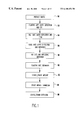
- FIG. 1 is a flow diagram of the preferred embodiment triple polysilicon method of forming a preferred embodiment integrated circuit including logic with embedded EEPROM cells;
- FIGS. 2A-D show the semiconductor wafer preparation step
- FIG. 3 show the step of forming a floating gate layer in cell areas
- FIGS. 4A-4E show the step of forming a polysilicon high voltage gate layer
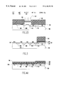
- FIGS. 5A-C show the step of defining logic device gates
- FIGS. 6A-B show the step of defining HiV gates and word lines
- FIGS. 7A-B show the step of defining individual cell floating gates
- FIGS. 8A-8E show the step of implanting device source/drain diffusions
- FIG. 9 shows the step of forming nitride on the device structure of FIG. 8E
- FIG. 10 shows the wafer after annealing to diffuse implanted source/drain dopant
- FIG. 11A is an expanded plan view of EEPROM cell area A in FIG. 10.
- FIG. 11B is an exploded view of the EEPROM cells in area of FIG. 11A
- FIG. 1 is a flow diagram of the preferred method of forming a triple polysilicon integrated circuit including logic with embedded EEPROM cells.
- High voltage (HiV) devices are included to interface between the chip logic and EEPROM cells.
- the HiV FETs are capable of withstanding the higher than normal voltage operating conditions experienced during an erase or write operation.
- a semiconductor wafer 100 preferably silicon, is prepared.
- pad oxide 102 and pad nitride 104 are formed on the wafer 100 .
- the pad oxide layer 102 is 15 nm thick and the pad nitride layer 104 is 172 nm thick.
- Shallow isolation trenches 106 , 108 , 110 and 112 are defined, preferably lithographically.
- trenches 106 , 108 , 110 and 112 are etched through pad oxide 102 , pad nitride 104 to a depth of about 500 nm into the silicon wafer 100 .
- the preferred embodiment manufacturing process is a complementary 25 insulated gate field effect transistor (FET) process commonly referred to as CMOS and includes both normal FETs and higher voltage FETs and floating gate cell devices.
- FET insulated gate field effect transistor
- CMOS complementary 25 insulated gate field effect transistor
- NFETs & PFETs both normal FETs and higher voltage FETs, referred to herein as NFETs & PFETs in areas 114 , 116 , HiV NFETs & HiV PFETs in areas 118 and 120 , respectively.
- Floating gate cell devices in areas 122 are referred to herein as EEPROM cell.
- the cross-section of the Figures is intended to illustrate formation of all five device variations.
- the shallow trenches 206 , 108 , 110 and 112 are filled with oxide, preferably TEOS, and the filled structure is annealed at 1000° C. for TEOS densification. Then, in FIG. 2B the pad nitride layer 104 is stripped, preferably using a hot phosphoric acid wet etch and the surface 124 is planarized.
- high voltage p-wells for HiV NFETs 118 and EEPROM cells 122 are defined.
- a mask 126 protects NFET areas 114 as well as PFET areas 116 and HiV PFET areas 120 .
- the unmasked surface areas of silicon wafer 100 are implanted to a level sufficient for high voltage threshold tailoring.
- boron is implanted 128 at 195 KeV to a dopant level of 2.0 ⁇ 10 12 cm ⁇ 2 , followed by BF 2 at 75 KeV to a dopant level of 8.0 ⁇ 10 12 cm ⁇ 2 .
- the mask 126 is removed using a dry strip and the wafer is cleaned using a S/N/O clean (sulfuric nitric ozone clean) to re-expose the surface 124 .
- high voltage FET n-wells are formed for HiV PFETs 118 .
- the surface 124 is masked 130 to protect normal PFET areas 116 , normal NFET areas 114 , HiV NFET areas 120 and EEPROM cells 122 , while leaving HiV PFET areas 118 exposed.
- the high voltage n-wells are doped using a two-step doping as represented by arrows 132 .
- arsenic is implanted at 1000 KeV to a dopant level of 4.0 ⁇ 10 13 cm ⁇ 2 , followed by antimony at 140 KeV to a dopant level of 2.0 ⁇ 10 12 cm ⁇ 2 .
- the resist 130 is stripped away using a dry strip and remaining pad oxide 102 is stripped from the surface 124 .
- wafer preparation step 50 is complete.
- a floating gate layer 134 is formed in cell areas. First, a 9.0 nm tunnel oxide layer 136 is grown on the surface 124 . Then, a 120.0 nm amorphous polysilicon floating gate layer 134 is grown on the tunnel oxide 136 . The floating gate layer 134 is implanted with a suitable dopant and an oxide-nitride-oxide (ONO) layer 138 is formed on the polysilicon floating gate layer 134 .
- ONO oxide-nitride-oxide
- the ONO layer 138 is formed by forming a 9.0 nm dry oxide layer on the amorphous polysilicon floating gate layer 134 , followed by deposition of an 8.5 nm layer of nitride and a subsequent 1.5-2.0 nm oxide layer.
- a mask pattern 140 is formed on the ONO layer 138 and the floating gate layer 134 is patterned by etching away exposed ONO and amorphous polysilicon. Remaining tunnel oxide on surface 124 is stripped away to re-expose the silicon surface 124 in device areas 114 , 116 , 118 and 120 .
- a high voltage device gate oxide layer 142 in FIG. 4A is formed on the bare surface 124 .
- a high voltage gate layer 144 of polysilicon is formed on the high voltage gate oxide layer.
- the high voltage gate oxide layer is 23.5 nm thick and the polysilicon gate layer 144 is 200.0 nm thick.
- a thin, 4.0 nm, oxide layer (not shown) is formed on the polysilicon high voltage gate layer 144 .
- a nitride layer 146 preferably 120.0 nm thick, is deposited on the thin oxide layer.
- a mask 148 is formed on nitride layer 146 over HiV PFET areas 118 , HiV PFET areas 120 and EEPROM areas 122 . Then, portions of polysilicon high voltage gate layer 144 , thin oxide layer and nitride layer 146 are selectively removed from PFET areas 114 and NFET areas 116 . Once the resist 148 is removed in FIG. 4C, the high voltage gate oxide layer is stripped away from the surface 124 in PFET areas 114 and NFET areas 116 . This is followed by growing a temporary protective oxide layer (not shown), preferably 10.0 nm thick, in PFET areas 114 and NFET areas 116 .
- an n-well mask 150 is formed on the structure of FIG. 4 C and the n-wells are implanted, as represented by arrows 152 .
- the n-well mask 150 is stripped away and a p-well mask, 154 in FIG. 4B, is formed.
- the p-wells are implanted, as represented by arrows 156 .
- the p-well mask 154 is stripped away.
- the exposed surface is cleaned to remove the oxide layer and a gate oxide layer is formed.
- the gate oxide is a 7.0 nm thick layer grown in N 2 O.
- step 56 logic device or normal FET gates are defined in areas 114 , 116 .
- a gate layer 158 of polysilicon is formed conformally.
- gate layer 158 is 200.0 nm thick and formed on the gate oxide layer.
- a mask pattern 160 is formed on the conformal polysilicon gate layer 158 to define the gates of all of the devices 114 , 116 , 118 , 120 and 122 .
- the gate mask pattern 160 is formed using a well known TEOS hard mask technique.
- the conformal polysilicon gate layer 158 is selectively removed so that, in FIG.
- PFET gates 162 and NFET gates 164 have been defined from the polysilicon gate layer 158 . Additionally, a high voltage gate hard mask 166 and EEPROM gate hard mask 168 pattern is formed from the patterned polysilicon gate layer 158 . Sidewall artifacts 170 remain along vertical edges.
- step 58 as represented in FIGS. 6A-B, HiV gates and word lines are defined.
- PFET gates 162 and NFET gates 164 are masked 172 and a dry etch is applied to etch away exposed nitride 146 , nitride remaining under mask pattern 160 .
- This nitride etch is followed by a polysilicon etch, which removes masking polysilicon pattern 166 , 168 and sidewall artifact 170 as it selectively removes high voltage gate layers 144 leaving, in FIG.
- HiV PFET gates 174 and HiV NFET gates 176 and EEPROM gates 168 ′ are comprised of portions of high voltage gate layers 144 , 146 .
- the sidewall artifacts 170 have also been removed. Etching ends at the ONO layer 138 on floating gate layer 134 .
- FIG. 7A illustrates the final floating gate definition step, wherein defined PFET gates 162 , NFET gates 164 , HiV PFET gates 174 and HiV NFET gates 176 masked 178 .
- Exposed portions of ONO layer 138 are etched to re-expose unmasked portions of floating gate layer 134 , which is subsequently selectively etched leaving word line stacks 180 , 182 defining EEPROM cells in FIG. 7 B.
- Each EEPROM gate cell includes a floating gate 180 f or 182 f and a word line 180 w or 182 w .
- PFET gates 162 After defining PFET gates 162 , NFET gates 164 , HiV PFET gates 174 , HiV NFET gates 176 , word lines 180 w , 182 w , and floating gates 180 f and 182 f , source and drains diffusions may be implemented.
- FIGS. 8A-E device source/drain diffusions are implanted.
- a diffusion mask 184 is formed on the structure of FIG. 7B to define areas for high voltage diffusion implant.
- Windows 186 and 188 are opened through the mask 184 , leaving HiV NFET areas 120 exposed and windows 188 are opened leaving bit line contact areas exposed in EEPROM areas 122 .
- Exposed areas are implanted (through the windows 186 , 188 ) with phosphorous, as represented by arrows 190 , to lightly dope both HiV NFET diffusions in areas 120 and EEPROM cell drain diffusions in bit line contacts in EEPROM areas 122 .
- the mask 184 is stripped away.
- nitride sidewalls 195 are formed on each of the gates 162 , 164 , 174 and 176 and word line stacks 180 and 182 .
- the nitride sidewalls 195 are formed by depositing a conformal layer of nitride, followed by a directional etch, e.g., a reactive ion etch (RIE), to remove nitride from horizontal surfaces.
- RIE reactive ion etch
- mask 200 which is essentially a negative of mask 196 , masks n-type regions, while PFET areas 114 and HiV PFET areas 118 are implanted with germanium and boron as represented by arrows 202 , to define p-type source drain diffusions and dope gates 162 , 174 .
- step 64 silicide is formed on the device structure.
- the mask 200 is stripped off of the wafer, preferably using a dry strip and, the wafer is cleaned.
- the wafer is annealed, preferably using a rapid thermal anneal, to activate dopants and repair any surface damage from dopant implants.
- a titanium layer is deposited, preferably using a sputter deposition technique.
- the titanium layer is annealed in nitrogen at to form Titanium Silicide on exposed regions.
- unreacted Titanium is stripped from away, followed by a silicide transformation anneal, which leaves gates 162 , 164 , 174 and 176 and word line stacks 180 and 182 capped with TiSi 2 204 .
- Source/drain areas are also silicided. From this point, processing would continue with conventional back end of the line processing as is well known in the art.
- FIG. 11A is an expanded plan view of EEPROM cell area A in FIG. 10 .
- FIG. 11B is an exploded view of the EEPROM cells of FIG. 11 A. Portions of four cells are shown in FIGS. 11A-B as represented by floating gate 182 f and floating gate portions 180 f , 228 and 230 .
- Word line 180 is capacitively coupled to floating gates 180 f and 228
- word line 182 is capacitively coupled to floating gates 182 f and 230 .
- Each bit line diffusion 224 , 232 is shared by four cells, only two of which are shown for each bit line diffusion 224 , 234 of FIGS. 11A-B.
- a source line 222 , 226 runs parallel to and, provides the source voltage for cells on one Word line 180 w , 182 w , respectively.
- Tunnel oxide 236 , 238 between the floating gates 180 f , 182 f , 228 , 230 and the surface 124 facilitates cell programming.
- cells such as in FIGS. 11A-B may be programmed, read, erased and reprogrammed by applying voltages to cell terminals as set forth in the table below.
- the triple polysilicon process of the preferred embodiment provides an integrated circuit logic chip with an embedded EPROM array without suffering the dilatory effects of prior art semiconductor processes.
Abstract
Description
| READ | WRITE | ERASE | ||
| Bit line | 1v | “0” = 5V | floating | ||
| “1” = 0V | |||||
| Word line | 3V | 10v | 0v | ||
| Source line | 0v | 0v | 10v | ||
Claims (12)
Priority Applications (7)
| Application Number | Priority Date | Filing Date | Title |
|---|---|---|---|
| US09/251,661 US6180456B1 (en) | 1999-02-17 | 1999-02-17 | Triple polysilicon embedded NVRAM cell and method thereof |
| CN99127057A CN1117398C (en) | 1999-02-17 | 1999-12-27 | Three-layer polycrystal cilicon inserted non-volatile memory unit and manufacture method thereof |
| GB0001002A GB2347016B (en) | 1999-02-17 | 2000-01-18 | Triple polysilicon embedded vnram cell |
| SG200000422A SG83184A1 (en) | 1999-02-17 | 2000-01-22 | Triple polysilicon embedded nvram cell and method thereof |
| JP2000035483A JP3452522B2 (en) | 1999-02-17 | 2000-02-14 | Method of manufacturing integrated circuit chip having embedded NVRAM array |
| TW089102421A TW456039B (en) | 1999-02-17 | 2000-02-14 | Triple polysilicon embedded NVRAM cell and method thereof |
| KR1020000007341A KR100359551B1 (en) | 1999-02-17 | 2000-02-16 | Triple polysilicon embedded nvram cell and method thereof |
Applications Claiming Priority (1)
| Application Number | Priority Date | Filing Date | Title |
|---|---|---|---|
| US09/251,661 US6180456B1 (en) | 1999-02-17 | 1999-02-17 | Triple polysilicon embedded NVRAM cell and method thereof |
Publications (1)
| Publication Number | Publication Date |
|---|---|
| US6180456B1 true US6180456B1 (en) | 2001-01-30 |
Family
ID=22952893
Family Applications (1)
| Application Number | Title | Priority Date | Filing Date |
|---|---|---|---|
| US09/251,661 Expired - Lifetime US6180456B1 (en) | 1999-02-17 | 1999-02-17 | Triple polysilicon embedded NVRAM cell and method thereof |
Country Status (7)
| Country | Link |
|---|---|
| US (1) | US6180456B1 (en) |
| JP (1) | JP3452522B2 (en) |
| KR (1) | KR100359551B1 (en) |
| CN (1) | CN1117398C (en) |
| GB (1) | GB2347016B (en) |
| SG (1) | SG83184A1 (en) |
| TW (1) | TW456039B (en) |
Cited By (9)
| Publication number | Priority date | Publication date | Assignee | Title |
|---|---|---|---|---|
| US6362049B1 (en) * | 1998-12-04 | 2002-03-26 | Advanced Micro Devices, Inc. | High yield performance semiconductor process flow for NAND flash memory products |
| US6653189B1 (en) * | 2000-10-30 | 2003-11-25 | Advanced Micro Devices, Inc. | Source side boron implant and drain side MDD implant for deep sub 0.18 micron flash memory |
| US6841824B2 (en) | 2002-09-04 | 2005-01-11 | Infineon Technologies Ag | Flash memory cell and the method of making separate sidewall oxidation |
| US20050118764A1 (en) * | 2003-11-28 | 2005-06-02 | Chou Anthony I. | Forming gate oxides having multiple thicknesses |
| US20060267134A1 (en) * | 2005-05-10 | 2006-11-30 | Armin Tilke | Deep trench isolation structures and methods of formation thereof |
| US20070128798A1 (en) * | 2005-12-07 | 2007-06-07 | Samsung Electronics Co., Ltd. | Nonvolatile memory device and method for fabricating the same |
| US7541277B1 (en) | 2008-04-30 | 2009-06-02 | International Business Machines Corporation | Stress relaxation, selective nitride phase removal |
| US20090140347A1 (en) * | 2007-12-04 | 2009-06-04 | International Business Machines Corporation | Method and structure for forming multiple self-aligned gate stacks for logic devices |
| CN100539155C (en) * | 2004-03-30 | 2009-09-09 | 精工电子有限公司 | Floating gate non-volatile memory |
Families Citing this family (6)
| Publication number | Priority date | Publication date | Assignee | Title |
|---|---|---|---|---|
| DE10101270A1 (en) * | 2001-01-12 | 2002-07-25 | Infineon Technologies Ag | Process for the production of embedded non-volatile semiconductor memory cells |
| KR100399350B1 (en) * | 2001-08-09 | 2003-09-26 | 삼성전자주식회사 | Non volatile memory having floating trap type device and method of forming the same |
| US6873538B2 (en) * | 2001-12-20 | 2005-03-29 | Micron Technology, Inc. | Programmable conductor random access memory and a method for writing thereto |
| US7009278B2 (en) * | 2003-11-24 | 2006-03-07 | Sharp Laboratories Of America, Inc. | 3d rram |
| JP4998934B2 (en) * | 2006-03-30 | 2012-08-15 | ルネサスエレクトロニクス株式会社 | Manufacturing method of semiconductor memory device |
| TWI622847B (en) * | 2017-01-10 | 2018-05-01 | 晶睿通訊股份有限公司 | Wide-angle illumination device |
Citations (14)
| Publication number | Priority date | Publication date | Assignee | Title |
|---|---|---|---|---|
| EP0379449A1 (en) | 1989-01-17 | 1990-07-25 | STMicroelectronics S.A. | Process for manufacturing integrated circuits |
| US5081054A (en) | 1989-04-03 | 1992-01-14 | Atmel Corporation | Fabrication process for programmable and erasable MOS memory device |
| US5086008A (en) | 1988-02-29 | 1992-02-04 | Sgs-Thomson Microelectronics S.R.L. | Process for obtaining high-voltage N channel transistors particularly for EEPROM memories with CMOS technology |
| US5254489A (en) | 1990-10-18 | 1993-10-19 | Nec Corporation | Method of manufacturing semiconductor device by forming first and second oxide films by use of nitridation |
| US5449634A (en) | 1992-10-27 | 1995-09-12 | Nec Corporation | Method of fabricating non-volatile semiconductor memory device |
| US5538912A (en) | 1993-02-01 | 1996-07-23 | Mitsubishi Denki Kabushiki Kaisha | Method of making memory cells with peripheral transistors |
| US5587332A (en) | 1992-09-01 | 1996-12-24 | Vlsi Technology, Inc. | Method of making flash memory cell |
| US5635416A (en) | 1994-05-04 | 1997-06-03 | Seiko Precision Inc. | Manufacturing method to fabricate a semiconductor integrated circuit with on-chip non-volatile memories |
| US5656527A (en) | 1990-09-22 | 1997-08-12 | Samsung Electronics Co., Ltd. | Method for fabricating a non-volatile semiconductor memory device having storage cell array and peripheral circuit, and a structure therefore |
| US5658813A (en) | 1993-06-28 | 1997-08-19 | Nec Corporation | Method for manufacturing a semiconductor integrated circuit device having a stack gate structure |
| US5756385A (en) | 1994-03-30 | 1998-05-26 | Sandisk Corporation | Dense flash EEPROM cell array and peripheral supporting circuits formed in deposited field oxide with the use of spacers |
| EP0892430A1 (en) | 1997-07-16 | 1999-01-20 | STMicroelectronics S.r.l. | Process for manufacturing an integrated circuit comprising an array of memory cells |
| US5888869A (en) * | 1996-06-27 | 1999-03-30 | Hyundai Electronics Industries, Co., Ltd. | Method of fabricating a flash memory device |
| US6004847A (en) * | 1995-06-30 | 1999-12-21 | Sgs-Thomson Microelectronics S.R.L. | Process for forming an integrated circuit comprising non-volatile memory cells and side transistors and corresponding IC |
Family Cites Families (4)
| Publication number | Priority date | Publication date | Assignee | Title |
|---|---|---|---|---|
| US379449A (en) * | 1888-03-13 | gondell | ||
| US5439840A (en) * | 1993-08-02 | 1995-08-08 | Motorola, Inc. | Method of forming a nonvolatile random access memory capacitor cell having a metal-oxide dielectric |
| US5567636A (en) * | 1995-02-27 | 1996-10-22 | Motorola Inc. | Process for forming a nonvolatile random access memory array |
| JP3165615B2 (en) * | 1995-03-17 | 2001-05-14 | 財団法人国際超電導産業技術研究センター | Surface elemental analysis method and device |
-
1999
- 1999-02-17 US US09/251,661 patent/US6180456B1/en not_active Expired - Lifetime
- 1999-12-27 CN CN99127057A patent/CN1117398C/en not_active Expired - Fee Related
-
2000
- 2000-01-18 GB GB0001002A patent/GB2347016B/en not_active Expired - Fee Related
- 2000-01-22 SG SG200000422A patent/SG83184A1/en unknown
- 2000-02-14 TW TW089102421A patent/TW456039B/en not_active IP Right Cessation
- 2000-02-14 JP JP2000035483A patent/JP3452522B2/en not_active Expired - Fee Related
- 2000-02-16 KR KR1020000007341A patent/KR100359551B1/en not_active IP Right Cessation
Patent Citations (14)
| Publication number | Priority date | Publication date | Assignee | Title |
|---|---|---|---|---|
| US5086008A (en) | 1988-02-29 | 1992-02-04 | Sgs-Thomson Microelectronics S.R.L. | Process for obtaining high-voltage N channel transistors particularly for EEPROM memories with CMOS technology |
| EP0379449A1 (en) | 1989-01-17 | 1990-07-25 | STMicroelectronics S.A. | Process for manufacturing integrated circuits |
| US5081054A (en) | 1989-04-03 | 1992-01-14 | Atmel Corporation | Fabrication process for programmable and erasable MOS memory device |
| US5656527A (en) | 1990-09-22 | 1997-08-12 | Samsung Electronics Co., Ltd. | Method for fabricating a non-volatile semiconductor memory device having storage cell array and peripheral circuit, and a structure therefore |
| US5254489A (en) | 1990-10-18 | 1993-10-19 | Nec Corporation | Method of manufacturing semiconductor device by forming first and second oxide films by use of nitridation |
| US5587332A (en) | 1992-09-01 | 1996-12-24 | Vlsi Technology, Inc. | Method of making flash memory cell |
| US5449634A (en) | 1992-10-27 | 1995-09-12 | Nec Corporation | Method of fabricating non-volatile semiconductor memory device |
| US5538912A (en) | 1993-02-01 | 1996-07-23 | Mitsubishi Denki Kabushiki Kaisha | Method of making memory cells with peripheral transistors |
| US5658813A (en) | 1993-06-28 | 1997-08-19 | Nec Corporation | Method for manufacturing a semiconductor integrated circuit device having a stack gate structure |
| US5756385A (en) | 1994-03-30 | 1998-05-26 | Sandisk Corporation | Dense flash EEPROM cell array and peripheral supporting circuits formed in deposited field oxide with the use of spacers |
| US5635416A (en) | 1994-05-04 | 1997-06-03 | Seiko Precision Inc. | Manufacturing method to fabricate a semiconductor integrated circuit with on-chip non-volatile memories |
| US6004847A (en) * | 1995-06-30 | 1999-12-21 | Sgs-Thomson Microelectronics S.R.L. | Process for forming an integrated circuit comprising non-volatile memory cells and side transistors and corresponding IC |
| US5888869A (en) * | 1996-06-27 | 1999-03-30 | Hyundai Electronics Industries, Co., Ltd. | Method of fabricating a flash memory device |
| EP0892430A1 (en) | 1997-07-16 | 1999-01-20 | STMicroelectronics S.r.l. | Process for manufacturing an integrated circuit comprising an array of memory cells |
Cited By (16)
| Publication number | Priority date | Publication date | Assignee | Title |
|---|---|---|---|---|
| US6362049B1 (en) * | 1998-12-04 | 2002-03-26 | Advanced Micro Devices, Inc. | High yield performance semiconductor process flow for NAND flash memory products |
| US6653189B1 (en) * | 2000-10-30 | 2003-11-25 | Advanced Micro Devices, Inc. | Source side boron implant and drain side MDD implant for deep sub 0.18 micron flash memory |
| US6841824B2 (en) | 2002-09-04 | 2005-01-11 | Infineon Technologies Ag | Flash memory cell and the method of making separate sidewall oxidation |
| US7081381B2 (en) | 2002-09-04 | 2006-07-25 | Infineon Technologies Ag | Flash memory cell and the method of making separate sidewall oxidation |
| US20050118764A1 (en) * | 2003-11-28 | 2005-06-02 | Chou Anthony I. | Forming gate oxides having multiple thicknesses |
| US7160771B2 (en) * | 2003-11-28 | 2007-01-09 | International Business Machines Corporation | Forming gate oxides having multiple thicknesses |
| CN100539155C (en) * | 2004-03-30 | 2009-09-09 | 精工电子有限公司 | Floating gate non-volatile memory |
| US7679130B2 (en) | 2005-05-10 | 2010-03-16 | Infineon Technologies Ag | Deep trench isolation structures and methods of formation thereof |
| US20060267134A1 (en) * | 2005-05-10 | 2006-11-30 | Armin Tilke | Deep trench isolation structures and methods of formation thereof |
| US8258028B2 (en) | 2005-05-10 | 2012-09-04 | Infineon Technologies Ag | Deep trench isolation structures and methods of formation thereof |
| US20100203703A1 (en) * | 2005-05-10 | 2010-08-12 | Armin Tilke | Deep Trench Isolation Structures and Methods of Formation Thereof |
| US7687846B2 (en) * | 2005-12-07 | 2010-03-30 | Samsung Electronics Co., Ltd. | Nonvolatile memory device |
| US20070128798A1 (en) * | 2005-12-07 | 2007-06-07 | Samsung Electronics Co., Ltd. | Nonvolatile memory device and method for fabricating the same |
| US20090140347A1 (en) * | 2007-12-04 | 2009-06-04 | International Business Machines Corporation | Method and structure for forming multiple self-aligned gate stacks for logic devices |
| US7790541B2 (en) * | 2007-12-04 | 2010-09-07 | International Business Machines Corporation | Method and structure for forming multiple self-aligned gate stacks for logic devices |
| US7541277B1 (en) | 2008-04-30 | 2009-06-02 | International Business Machines Corporation | Stress relaxation, selective nitride phase removal |
Also Published As
| Publication number | Publication date |
|---|---|
| SG83184A1 (en) | 2001-09-18 |
| CN1117398C (en) | 2003-08-06 |
| CN1264179A (en) | 2000-08-23 |
| TW456039B (en) | 2001-09-21 |
| GB0001002D0 (en) | 2000-03-08 |
| KR20000062558A (en) | 2000-10-25 |
| KR100359551B1 (en) | 2002-11-07 |
| JP3452522B2 (en) | 2003-09-29 |
| GB2347016A (en) | 2000-08-23 |
| JP2000243938A (en) | 2000-09-08 |
| GB2347016B (en) | 2003-07-02 |
Similar Documents
| Publication | Publication Date | Title |
|---|---|---|
| US4822750A (en) | MOS floating gate memory cell containing tunneling diffusion region in contact with drain and extending under edges of field oxide | |
| US4701776A (en) | MOS floating gate memory cell and process for fabricating same | |
| US6627928B2 (en) | Method of manufacturing an integrated circuit, for integrating an electrically programmable, non-volatile memory and high-performance logic circuitry in the same semiconductor chip | |
| KR100295000B1 (en) | 2f-square memory cell for gigabit memory applications | |
| US6265292B1 (en) | Method of fabrication of a novel flash integrated circuit | |
| US6074914A (en) | Integration method for sidewall split gate flash transistor | |
| KR100718903B1 (en) | Semiconductor storage device and its manufacturing method | |
| US6251731B1 (en) | Method for fabricating high-density and high-speed nand-type mask roms | |
| US6087211A (en) | Method for forming a semiconductor device having non-volatile memory cells, High-voltage transistors, and low-voltage, deep sub-micron transistors | |
| US20030203557A1 (en) | Method and structure for an improved floating gate memory cell | |
| US6180456B1 (en) | Triple polysilicon embedded NVRAM cell and method thereof | |
| JP2002289715A (en) | Method of fabricating twin monos cell and array organization | |
| KR20010074775A (en) | A single polysilicon flash eeprom and method for making same | |
| US9780107B2 (en) | Methods of forming integrated circuit devices | |
| KR19990075948A (en) | Method for manufacturing non-volatile memory device using self-aligned source process | |
| US6917070B2 (en) | Single-poly EPROM and method for forming the same | |
| US5385856A (en) | Manufacture of the fieldless split-gate EPROM/Flash EPROM | |
| EP0160003B1 (en) | Mos floating gate memory cell and process for fabricating same | |
| US6448137B1 (en) | Method of forming an NROM embedded with mixed-signal circuits | |
| US7016225B2 (en) | Four-bit non-volatile memory transistor and array | |
| US6482699B1 (en) | Method for forming self-aligned contacts and local interconnects using decoupled local interconnect process | |
| US20050037572A1 (en) | Methods of fabricating flash memory devices including word lines with parallel sidewalls and related devices | |
| US6448126B1 (en) | Method of forming an embedded memory | |
| KR100214813B1 (en) | Semiconductor device mask rom and fabrication method thereof | |
| EP0637402B1 (en) | Method of making a dual-poly non-volatile memory device using a third polysilicon layer |
Legal Events
| Date | Code | Title | Description |
|---|---|---|---|
| AS | Assignment |
Owner name: INTERNATIONAL BUSINESS MACHINES CORPORATION, NEW Y Free format text: ASSIGNMENT OF ASSIGNORS INTEREST;ASSIGNORS:LAM, CHUNG HON;MILES, GLEN L.;NAKOS, JAMES SPIROS;AND OTHERS;REEL/FRAME:009774/0354;SIGNING DATES FROM 19990205 TO 19990208 |
|
| STCF | Information on status: patent grant |
Free format text: PATENTED CASE |
|
| FPAY | Fee payment |
Year of fee payment: 4 |
|
| FPAY | Fee payment |
Year of fee payment: 8 |
|
| REMI | Maintenance fee reminder mailed | ||
| FPAY | Fee payment |
Year of fee payment: 12 |
|
| SULP | Surcharge for late payment |
Year of fee payment: 11 |
|
| AS | Assignment |
Owner name: GLOBALFOUNDRIES U.S. 2 LLC, NEW YORK Free format text: ASSIGNMENT OF ASSIGNORS INTEREST;ASSIGNOR:INTERNATIONAL BUSINESS MACHINES CORPORATION;REEL/FRAME:036550/0001 Effective date: 20150629 |
|
| AS | Assignment |
Owner name: GLOBALFOUNDRIES INC., CAYMAN ISLANDS Free format text: ASSIGNMENT OF ASSIGNORS INTEREST;ASSIGNORS:GLOBALFOUNDRIES U.S. 2 LLC;GLOBALFOUNDRIES U.S. INC.;REEL/FRAME:036779/0001 Effective date: 20150910 |
|
| AS | Assignment |
Owner name: WILMINGTON TRUST, NATIONAL ASSOCIATION, DELAWARE Free format text: SECURITY AGREEMENT;ASSIGNOR:GLOBALFOUNDRIES INC.;REEL/FRAME:049490/0001 Effective date: 20181127 |
|
| AS | Assignment |
Owner name: GLOBALFOUNDRIES INC., CAYMAN ISLANDS Free format text: RELEASE BY SECURED PARTY;ASSIGNOR:WILMINGTON TRUST, NATIONAL ASSOCIATION;REEL/FRAME:054636/0001 Effective date: 20201117 |
|
| AS | Assignment |
Owner name: GLOBALFOUNDRIES U.S. INC., NEW YORK Free format text: RELEASE BY SECURED PARTY;ASSIGNOR:WILMINGTON TRUST, NATIONAL ASSOCIATION;REEL/FRAME:056987/0001 Effective date: 20201117 |