US6181386B1 - Projecting images - Google Patents
Projecting images Download PDFInfo
- Publication number
- US6181386B1 US6181386B1 US08/767,967 US76796796A US6181386B1 US 6181386 B1 US6181386 B1 US 6181386B1 US 76796796 A US76796796 A US 76796796A US 6181386 B1 US6181386 B1 US 6181386B1
- Authority
- US
- United States
- Prior art keywords
- image
- linear
- retarder
- reflecting polarizer
- imaging screen
- Prior art date
- Legal status (The legal status is an assumption and is not a legal conclusion. Google has not performed a legal analysis and makes no representation as to the accuracy of the status listed.)
- Expired - Fee Related
Links
Images


Classifications
-
- H—ELECTRICITY
- H04—ELECTRIC COMMUNICATION TECHNIQUE
- H04N—PICTORIAL COMMUNICATION, e.g. TELEVISION
- H04N9/00—Details of colour television systems
- H04N9/12—Picture reproducers
- H04N9/31—Projection devices for colour picture display, e.g. using electronic spatial light modulators [ESLM]
- H04N9/3141—Constructional details thereof
-
- G—PHYSICS
- G03—PHOTOGRAPHY; CINEMATOGRAPHY; ANALOGOUS TECHNIQUES USING WAVES OTHER THAN OPTICAL WAVES; ELECTROGRAPHY; HOLOGRAPHY
- G03B—APPARATUS OR ARRANGEMENTS FOR TAKING PHOTOGRAPHS OR FOR PROJECTING OR VIEWING THEM; APPARATUS OR ARRANGEMENTS EMPLOYING ANALOGOUS TECHNIQUES USING WAVES OTHER THAN OPTICAL WAVES; ACCESSORIES THEREFOR
- G03B21/00—Projectors or projection-type viewers; Accessories therefor
- G03B21/10—Projectors with built-in or built-on screen
-
- G—PHYSICS
- G03—PHOTOGRAPHY; CINEMATOGRAPHY; ANALOGOUS TECHNIQUES USING WAVES OTHER THAN OPTICAL WAVES; ELECTROGRAPHY; HOLOGRAPHY
- G03B—APPARATUS OR ARRANGEMENTS FOR TAKING PHOTOGRAPHS OR FOR PROJECTING OR VIEWING THEM; APPARATUS OR ARRANGEMENTS EMPLOYING ANALOGOUS TECHNIQUES USING WAVES OTHER THAN OPTICAL WAVES; ACCESSORIES THEREFOR
- G03B21/00—Projectors or projection-type viewers; Accessories therefor
- G03B21/54—Accessories
- G03B21/56—Projection screens
- G03B21/60—Projection screens characterised by the nature of the surface
- G03B21/606—Projection screens characterised by the nature of the surface for relief projection
-
- G—PHYSICS
- G06—COMPUTING; CALCULATING OR COUNTING
- G06F—ELECTRIC DIGITAL DATA PROCESSING
- G06F1/00—Details not covered by groups G06F3/00 - G06F13/00 and G06F21/00
- G06F1/16—Constructional details or arrangements
- G06F1/1601—Constructional details related to the housing of computer displays, e.g. of CRT monitors, of flat displays
-
- G—PHYSICS
- G09—EDUCATION; CRYPTOGRAPHY; DISPLAY; ADVERTISING; SEALS
- G09F—DISPLAYING; ADVERTISING; SIGNS; LABELS OR NAME-PLATES; SEALS
- G09F13/00—Illuminated signs; Luminous advertising
- G09F13/04—Signs, boards or panels, illuminated from behind the insignia
- G09F13/0418—Constructional details
- G09F13/0422—Reflectors
-
- H—ELECTRICITY
- H04—ELECTRIC COMMUNICATION TECHNIQUE
- H04N—PICTORIAL COMMUNICATION, e.g. TELEVISION
- H04N5/00—Details of television systems
- H04N5/74—Projection arrangements for image reproduction, e.g. using eidophor
- H04N5/7408—Direct viewing projectors, e.g. an image displayed on a video CRT or LCD display being projected on a screen
-
- G—PHYSICS
- G09—EDUCATION; CRYPTOGRAPHY; DISPLAY; ADVERTISING; SEALS
- G09F—DISPLAYING; ADVERTISING; SIGNS; LABELS OR NAME-PLATES; SEALS
- G09F13/00—Illuminated signs; Luminous advertising
- G09F13/04—Signs, boards or panels, illuminated from behind the insignia
- G09F13/14—Arrangements of reflectors therein
- G09F2013/145—Arrangements of reflectors therein curved reflectors
-
- H—ELECTRICITY
- H04—ELECTRIC COMMUNICATION TECHNIQUE
- H04N—PICTORIAL COMMUNICATION, e.g. TELEVISION
- H04N9/00—Details of colour television systems
- H04N9/12—Picture reproducers
- H04N9/31—Projection devices for colour picture display, e.g. using electronic spatial light modulators [ESLM]
- H04N9/3141—Constructional details thereof
- H04N9/3147—Multi-projection systems
Definitions
- the invention relates to projecting images.
- light projectors are used, for example, to display images on large surfaces, such as movie or television screens.
- a front projection system 20 an image beam 24 is projected from an image source 21 onto the “front” side of a reflection-type angle transforming screen, which then reflects the light toward a viewer 27 positioned in front of the screen.
- the image beam is projected onto the “rear” side of a transmission-type angle transforming screen 26 and transmitted toward a viewer 29 located in front of the screen.
- the size of the image beam 24 when it reaches the screen 26 depends upon the magnification rate of the image source 21 and the distance between the screen 26 and the image source 22 .
- the image beam 24 should just fill the entire height S and width (not shown) of the screen 26 .
- the image beam 24 fills the screen 26 when the source 22 is at an appropriate distance D from the screen 26 , i.e., when the center of the image beam 24 follows an optical path 28 of length D.
- the optical path length D depends upon the screen height S and the magnification rate of the image source. Any non-transparent object placed in the path of the image beam 24 typically will obstruct the image beam 24 and form a shadow on the screen 26 .
- the “folded” system 30 includes one or more mirrors 34 , 36 placed at strategic points along the optical path to redirect the projected image and to form multiple optical subpaths D 1 , D 2 , D 3 .
- the overall system configuration in this optical system 30 is more rectilinear than the conical system configuration of FIG. 1 .
- the image 38 fills the screen 32 entirely when the mirrors 34 , 36 are positioned such that the combined length of the optical subpaths D 1 , D 2 , and D 3 equals the optical path length D in FIG. 1, even though the apparent projection length L is less than D.
- An “extra-folded” projection display system includes a selectively reflective material (e.g., a linear reflecting polarizer) placed immediately behind the system's imaging screen.
- the display system includes an image projector that projects an image beam containing light of a predetermined linear polarization toward the imaging screen.
- the linear reflecting polarizer reflects the light in the image beam away from the screen.
- the reflected image beam then encounters a 1 ⁇ 4-wavelength achromatic retarder which converts the linear polarization to circular polarization.
- the image beam next hits a mirror that reflects the light back through the 1 ⁇ 4-wavelength achromatic retarder, which converts the circular polarization back to linear polarization, with the polarization director rotated 90° from the original polarization director.
- the linear reflecting polarizer then allows the light to pass through to the image screen.
- Embodiments of the invention may include the following features.
- the system may include a powered optical element to further increase the “folding” of the image beam, change the magnification rate, provide distortion correction, or optimize packaging.
- the image beam may be folded even further by allowing it to reflect from the mirror twice and to pass through the achromatic retarder four times.
- the mirror may be positioned between the image source and the imaging screen.
- An optical element placed immediately behind the screen in a projection imaging system may act as a “mirror” that increases the amount of folding that the light undergoes and therefore may reduce the apparent projection length, or depth, of the system to a greater extent than previously possible.
- the image source may be placed behind all optical elements in the display system, further reducing the size of the system.
- FIG. 1 is a side view of a prior art projection display system.
- FIG. 2 is a side view of a prior art folded projection display system.
- FIGS. 3, 4 , and 5 are side views of an “extra-folded” projection display system.
- FIGS. 6A and 6B are “patchwork” polarizers that may be used in the system of FIGS. 3, 4 , and 5 .
- FIGS. 7A, 7 B, and 7 C are specialized achromatic retarders that may be used in the system of FIGS. 3, 4 , and 5 .
- FIGS. 8, 9 , and 10 are side views of alternative “extra-folded” projection video systems.
- FIGS. 11A and 11B are side and front views of a configuration of multiple projection video systems of FIG. 8 .
- FIGS. 12A and 12B are side and front views of a configuration of multiple projection video systems of FIG. 9 .
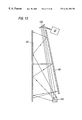
- FIGS. 13, 14 A, and 14 B are side views of alternative “extra-folded” projection video systems with powered optical devices.
- FIG. 15 is a computer system having an “extra-folded” projection video display.
- an “extra-folded” projection video system 50 such as a projection television, includes a diffusive screen 52 having a surface 54 that is covered by a selectively reflective or transmissive material.
- the selectively reflective or transmissive surface 54 allows the screen 52 to act at times as a mirror and at times as a transmissive imaging screen.
- an image 55 contained in an image beam 56 projected by an image projector 58 reflects from the rear surface 54 of the screen the first time it encounters the surface 54 .
- the image beam 56 then travels toward a mirror 60 located behind the screen 52 , which in turn reflects the light 56 back toward the screen 52 .
- the image 55 in the image beam 56 encounters the rear surface 54 of the screen 52 the second time, the image 55 passes through the screen 52 toward the viewer 62 .
- the screen 52 essentially acts as a “mirror” placed directly between the viewer 62 and the rear mirror 60 .
- the screen 52 reflects the image beam 56 away from the viewer but does not block the image beam 56 or significantly deteriorate the quality of the image 55 seen by the viewer. Because a “mirror” is placed at a position along the optical path that previously had to be free from such objects, the image beam 56 projected from the image source 58 is “extra-folded”, i.e., folded more often and over a much smaller linear distance L′ than is possible with existing systems.
- the projection system 50 receives an electronic signal through an input cable 51 and provides it to a signal splitter 53 .
- the signal splitter 53 divides the electronic signal into a video signal and an audio signal and provides these signals to the image source 58 and a sound system 57 , respectively.
- the image source 58 converts the video signal into light and projects the light as an image beam 56 .
- the image source 58 may be any type of image projection engine, such as a liquid crystal display (“LCD”)projector.
- the electronic signal may be any type of signal containing video information, such as a television signal received by an antenna or over cable lines or a computer video signal received through a computer video cable.
- the audio signal and the sound system 57 are optional.
- the screen 52 is able to act as a mirror at some times and as an imaging screen at other times because its rear surface 54 is covered by a linear reflecting polarizing material, such as Minnesota Mining & Manufacturing Company's double brightness enhancement film (DBEF) material.
- the linear reflecting polarizing material forms a polarizer 64 that transmits substantially all light linearly polarized in one direction (the “direction of transmission”)and reflects substantially all light linearly polarized in a direction orthogonal to the direction of transmission.
- the linear reflecting polarizer 64 is oriented to transmit p-polarized light, it reflects substantially all s-polarized light because s-polarized light is orthogonal to the polarizer's direction of greatest transmissive efficiency.
- the linear reflecting polarizer should have a transmission efficiency of at least 99%, so that less than 1% of s-polarized light escapes the projection system and all but 1% of p-polarized light is projected to the viewer.
- a linear absorption polarizer 68 may be used to further filter improperly polarized light from the image beam. Both the reflecting polarizer 64 and the absorption polarizer 68 may be attached to the screen 52 (e.g., by an index matching glue) or may be suspended in the display system (e.g., by a one or more frames connected to the system's housing).
- the polarization of the light traveling between the image source 58 and the imaging screen 52 is altered by a 1 ⁇ 4-wavelength achromatic retarder 70 positioned between the imaging screen 52 and the rear mirror 60 .
- the retarder 70 may be attached to the front surface of the mirror 60 or suspended in the system by other means.
- the 1 ⁇ 4-wavelength achromatic retarder 70 comprises a material that delays one linear component of a light wave passing through it by 1 ⁇ 4-wavelength. Such a material is produced by Nitto Denko Corporation of Japan under the name WB-1 ⁇ 4, and similar materials are available from other sources. Therefore, the retarder 70 transforms linearly polarized light into circularly polarized light and transforms circularly polarized light into linearly polarized light. Furthermore, light that twice passes through the retarder 70 has the same linear component delayed twice, or by 1 ⁇ 2-wavelength. So linearly polarized light passing through the retarder 70 two times emerges with a polarization orthogonal to that at which it began.
- s-polarized light 72 travelling along optical sub-path D 2 ′ is transformed into circularly polarized light 74 when it passes through the achromatic retarder 70 .
- the circularly polarized light 74 becomes p-polarized light 76 when it passes through the retarder 70 again.
- the p-polarized light 76 then travels along optical sub-path D 3 ′ and eventually passes through the linear reflecting polarizer 64 and onto the diffusive imaging screen 52 .
- the “extra-folded” projection system can include a “patchwork” polarizer 90 or 92 that compensates for trapezoidal distortions occurring when the image is reflected in the system.
- the linear reflecting polarizing material 64 may be slightly sensitive as to the incoming angle of the light. That is, the polarization of the reflected light may not be perfectly s-polarized but may be slightly circular.
- the patchwork polarizer 90 or 92 compensates for this potential condition.
- the patchwork polarizer 90 or 92 may be located anywhere between the image source 58 and the last reflective element in the system.
- the “patchwork” polarizer 90 of FIG. 6A may be placed within the image source 58 (FIG. 3 ), such as on the surface of the lens that typically forms the last stage of an LCD projector.
- the substantially circular polarizer 90 is a linear absorption polarizer having several regions 90 a - 90 f with different transmissive properties. Each pair of adjacent regions is divided by a linear boundary 91 a - 91 e extending through the polarizer 90 .
- the polarizer 92 of FIG. 6B may be placed on one of the reflective surfaces in the display system and preferably is incorporated into the DBEF material of the linear reflecting polarizer 64 (FIG. 4) on the system's display screen 52 .
- the transmissive properties, size, and shape of each region in the patchwork polarizer 90 or 92 are determined by the structure of the display system and, in particular, by the trapezoidal distortions imparted by the system.
- the achromatic retarder 70 can be constructed to accommodate the varying angles of incidence at which light from the image source 58 impinges upon the retarder 70 . If the image source is located below the page and toward the reader, light from the image source will hit the page at higher angles of incidence on the lower half of the page and at lower angles of incidence on the upper half of the page. Likewise, if the image source is positioned below the center of the page, light from the source will hit the page at higher angles of incidence on the center of the page and at lower angles of incidence on the left and right edges of the page. Because the retarder's effect on a particular light ray may depend upon the angle of incidence at which the light ray strikes the retarder, the retarder 70 can consist of several regions having different retardation properties.
- the retarder 70 may be divided into two regions 69 a , 69 b having two different retardation values ⁇ 1 and ⁇ 2 .
- Region 69 a accommodates light passing through the retarder 70 at lower angles of incidence
- region 69 b accommodates light passing through at the higher angles of incidence.
- the retarder instead may be divided into a linear grid having, e.g., two retardation values ⁇ 1 and ⁇ 2 along a vertical axis ⁇ and three retardation values ⁇ 1 , ⁇ 2 , and ⁇ 1 along a horizontal axis ⁇ .
- the retarder 70 then is divided into six sections 71 a - 71 b , the retardation value for each of which is determined by the corresponding vertical value ⁇ 1 or ⁇ 2 and the corresponding horizontal value ⁇ 1 , ⁇ 2 , or ⁇ 3 .
- the retarder 70 may be divided into several substantially circular or elliptical regions 73 a - 73 h intersecting at the center point 75 of the retarder's bottom edge 77 .
- the innermost region 73 a accommodates light passing through the retarder 70 at the highest angles of incidence and the outermost region 73 h accommodates light passing through the retarder 70 at the lowest angles of incidence.
- a retarder manufacturer e.g., Nitto Denko Corporation of Japan
- the “extra-folded” projection display system 50 may be constructed with various spacial configurations.
- the image source 58 projects an image beam directly onto the linear reflecting polarizer 64 , which first reflects the image beam toward the achromatic retarder 70 and then allows the reflected image beam to pass to the imaging screen 52 .
- the image source 58 is located behind the mirror 60 .
- the image source 58 projects an image beam downward onto a smaller mirror 100 that in turn reflects the image beam toward the linear reflecting polarizer 64 .
- the linear reflecting polarizer 64 then reflects the image beam toward the achromatic retarder 70 and the rear mirror 60 , and then allows the reflected p-polarized light to pass to the display surface 52 .
- the “extra folded” projection display system 50 may be folded even further by allowing the image beam to reflect (or “bounce”)from the rear mirror 60 twice, instead of the single bounce shown in FIG. 3 .
- the image source 58 projects p-polarized light directly toward the rear mirror 60 .
- the light in the image beam 56 has s-polarization.
- the s-polarized light then reflects from the linear reflecting polarizer on the screen 52 back toward the rear mirror 60 .
- Another reflection from the mirror 60 and two additional passes through the achromatic retarder direct the image beam, which again contains p-polarized light, back toward the screen 52 , where the light passes through the linear reflecting polarizer to form images on the imaging screen 52 .
- FIG. 11A is a side view of an arrangement of multiple units of the projection display system 50 of FIG. 8 .
- Each unit 250 a , 250 b includes an outer housing 200 .
- the housing 200 mounts the screen 52 , the mirror 60 , and the image projector 58 in the proper positions.
- the bottom front surface 202 of the housing 200 is recessed below the screen 52 to allow stacking, as shown in FIG. 11A, so that the screens 52 of the units 250 a , 250 b are substantially coplanar.
- a support 204 mounted on the back surface of the lower unit 250 b holds the upper unit 250 a in place. Referring to FIG. 11B, the front view of the arrangement is shown.
- the screen 52 is approximately the width of the unit 250 a , so that there is very little border.
- a plurality of units 250 a - 250 d can be arranged in an array or “tiled” configuration with very little gap between individual units.
- FIG. 12A is a side view of an arrangement of multiple units of the projection display system 50 of FIG. 9 .
- Each unit 260 a , 260 b includes an outer housing 210 .
- the outer housing is substantially a rectangular parallelepiped, unlike the recessed and angled shape of housing 200 in FIG. 11 A.
- the imaging screen 52 goes to substantially the edge of the housing 210 on all four sides, without a recessed surface 202 as in housing 200 (FIGS. 11 A and 11 B).
- FIG. 12B is the front view of the arrangement of FIG. 12 A.
- the design of FIG. 9 thus has trade offs with the design of FIG. 8 relating to depth and base dimensions, with the final use affecting the choice of designs.
- the image source 58 is placed behind the rear mirror 60 near the top of the projection system.
- the image source 58 projects the image beam upward onto a small mirror 102 at the top of the projection system.
- the small mirror 102 in turn reflects the image beam downward and onto a larger mirror 104 located at the bottom of the projection system.
- the image source 58 projects the image beam with only slight divergence (or magnification).
- the lower mirror 104 is a “powered” optical device that magnifies the image beam as it reflects the beam toward the linear reflecting polarizer 64 .
- the lower mirror 104 magnifies the image beam enough to fill the entire surface of the imaging screen after reflecting once from the linear reflecting polarizer 64 and once from the rear mirror 60 .
- the upper mirror 102 also may be a “powered” optical device, as shown in FIG. 14 A.
- the upper mirror may be a “negatively powered” optical device that causes the image beam to converge until it reaches the lower mirror 104 , as shown in FIG. 14 B.
- an “extra-folded” image projection system may be incorporated into a computer display 106 small enough for use with a desktop computer 108 .
- the projection display subsystem 106 may be driven by a conventional CPU 112 and video controller 113 that provide video data to the projection display subsystem 106 through a standard video cable 114 . Because the screen 116 is used as a “mirror” to “fold” the video image into a very small area, the projection display subsystem 106 combines the benefits of flat screen technology and projection video yet requires only a small area on the desktop.
- the video projection system may be incorporated into many types of video display systems, such as small and large screen televisions, laptop and desktop computers, overhead projectors, movie theaters, and holographic imaging systems.
Abstract
Description
Claims (21)
Priority Applications (7)
| Application Number | Priority Date | Filing Date | Title |
|---|---|---|---|
| US08/767,967 US6181386B1 (en) | 1995-12-29 | 1996-12-17 | Projecting images |
| CA002193790A CA2193790C (en) | 1995-12-29 | 1996-12-23 | Projecting images |
| IL11989796A IL119897A (en) | 1995-12-29 | 1996-12-24 | Apparatus for projecting images |
| AU76496/96A AU725776B2 (en) | 1995-12-29 | 1996-12-24 | Projecting images |
| TW085116237A TW351042B (en) | 1995-12-29 | 1996-12-28 | Projecting images the invention relates to projecting images |
| US09/715,057 US6339454B1 (en) | 1995-12-29 | 2000-11-20 | Projecting images |
| US10/043,228 US6580471B2 (en) | 1995-12-29 | 2002-01-14 | Projecting images |
Applications Claiming Priority (2)
| Application Number | Priority Date | Filing Date | Title |
|---|---|---|---|
| US58110895A | 1995-12-29 | 1995-12-29 | |
| US08/767,967 US6181386B1 (en) | 1995-12-29 | 1996-12-17 | Projecting images |
Related Parent Applications (1)
| Application Number | Title | Priority Date | Filing Date |
|---|---|---|---|
| US58110895A Continuation-In-Part | 1995-12-29 | 1995-12-29 |
Related Child Applications (1)
| Application Number | Title | Priority Date | Filing Date |
|---|---|---|---|
| US09/715,057 Continuation US6339454B1 (en) | 1995-12-29 | 2000-11-20 | Projecting images |
Publications (1)
| Publication Number | Publication Date |
|---|---|
| US6181386B1 true US6181386B1 (en) | 2001-01-30 |
Family
ID=24323920
Family Applications (1)
| Application Number | Title | Priority Date | Filing Date |
|---|---|---|---|
| US08/767,967 Expired - Fee Related US6181386B1 (en) | 1995-12-29 | 1996-12-17 | Projecting images |
Country Status (8)
| Country | Link |
|---|---|
| US (1) | US6181386B1 (en) |
| EP (1) | EP0783133A1 (en) |
| JP (1) | JPH1073883A (en) |
| CN (1) | CN1165963A (en) |
| BR (1) | BR9606208A (en) |
| NO (1) | NO965613L (en) |
| NZ (1) | NZ314011A (en) |
| TW (1) | TW351042B (en) |
Cited By (26)
| Publication number | Priority date | Publication date | Assignee | Title |
|---|---|---|---|---|
| US6323999B1 (en) * | 1999-08-04 | 2001-11-27 | Minolta Co., Ltd. | Image display apparatus |
| WO2002021205A1 (en) * | 2000-09-08 | 2002-03-14 | Sony Electronics, Inc. | Footprint reduction in a rear projection television system |
| US6390626B2 (en) * | 1996-10-17 | 2002-05-21 | Duke University | Image projection system engine assembly |
| US20030025886A1 (en) * | 2001-07-30 | 2003-02-06 | Canon Kabushiki Kaisha | Method of manufacturing different types of image display apparatuses and image display apparatus manufactured by the method |
| US6561649B1 (en) * | 1999-07-09 | 2003-05-13 | Sarnoff Corporation | Compact rear projection system using birefringent optics |
| US6580471B2 (en) * | 1995-12-29 | 2003-06-17 | Duke University | Projecting images |
| US6616283B1 (en) * | 1999-09-22 | 2003-09-09 | Canon Kabushiki Kaisha | Projector |
| US6873460B1 (en) | 1999-07-09 | 2005-03-29 | Sarnoff Corporation | Retractable rear projection display |
| US20050099606A1 (en) * | 2001-10-01 | 2005-05-12 | Yoshimasa Fushimi | Projection type display apparatus rear projection and multi-vision system |
| US20070165307A1 (en) * | 2004-12-06 | 2007-07-19 | Perkins Raymond T | Inorganic, Dielectric, Grid Polarizer and Non-Zero Order Diffraction Grating |
| US20070296921A1 (en) * | 2006-06-26 | 2007-12-27 | Bin Wang | Projection display with a cube wire-grid polarizing beam splitter |
| US20080055723A1 (en) * | 2006-08-31 | 2008-03-06 | Eric Gardner | Durable, Inorganic, Absorptive, Ultra-Violet, Grid Polarizer |
| US20080266662A1 (en) * | 2004-12-06 | 2008-10-30 | Perkins Raymond T | Polarization device to polarize and further control light |
| US20080278811A1 (en) * | 2004-12-06 | 2008-11-13 | Perkins Raymond T | Selectively Absorptive Wire-Grid Polarizer |
| US20080284984A1 (en) * | 2007-05-17 | 2008-11-20 | Hansen Douglas P | Projection Device with a Folded Optical Path and Wire-Grid Polarizer |
| US20080316599A1 (en) * | 2007-06-22 | 2008-12-25 | Bin Wang | Reflection-Repressed Wire-Grid Polarizer |
| US20090168171A1 (en) * | 2004-12-06 | 2009-07-02 | Perkins Raymond T | Multilayer wire-grid polarizer with off-set wire-grid and dielectric grid |
| US20100103517A1 (en) * | 2008-10-29 | 2010-04-29 | Mark Alan Davis | Segmented film deposition |
| US8248696B2 (en) | 2009-06-25 | 2012-08-21 | Moxtek, Inc. | Nano fractal diffuser |
| US8611007B2 (en) | 2010-09-21 | 2013-12-17 | Moxtek, Inc. | Fine pitch wire grid polarizer |
| US8873144B2 (en) | 2011-05-17 | 2014-10-28 | Moxtek, Inc. | Wire grid polarizer with multiple functionality sections |
| US8913321B2 (en) | 2010-09-21 | 2014-12-16 | Moxtek, Inc. | Fine pitch grid polarizer |
| US8913320B2 (en) | 2011-05-17 | 2014-12-16 | Moxtek, Inc. | Wire grid polarizer with bordered sections |
| US8922890B2 (en) | 2012-03-21 | 2014-12-30 | Moxtek, Inc. | Polarizer edge rib modification |
| US9348076B2 (en) | 2013-10-24 | 2016-05-24 | Moxtek, Inc. | Polarizer with variable inter-wire distance |
| US10095097B2 (en) * | 2016-11-29 | 2018-10-09 | Hyundai Motor Company | Projection-type optical module |
Families Citing this family (29)
| Publication number | Priority date | Publication date | Assignee | Title |
|---|---|---|---|---|
| US6483612B2 (en) | 1998-04-15 | 2002-11-19 | Duke University | Projection screen apparatus including holographic optical element |
| US6788460B2 (en) | 1998-04-15 | 2004-09-07 | Duke University | Projection screen apparatus |
| WO1998019213A1 (en) * | 1996-10-31 | 1998-05-07 | Sanyo Electric Co., Ltd. | Back projection display |
| FR2764462A1 (en) | 1997-06-10 | 1998-12-11 | Thomson Multimedia Sa | IMPROVEMENT IN PROJECTION SYSTEMS |
| US6204901B1 (en) | 1997-07-31 | 2001-03-20 | Duke University | Liquid crystal color shutters that include reflective polarizers that pass color components of light of a first polarization and that reflect a majority of color components of light of a second polarization |
| CN1269892A (en) * | 1997-09-09 | 2000-10-11 | 美国3M公司 | Rear projection display |
| US5867239A (en) | 1997-10-17 | 1999-02-02 | Minnesota Mining And Manufacturing Company | Wide angle optical retarder |
| US6163402A (en) * | 1998-06-11 | 2000-12-19 | 3M Innovative Properties Company | Rear projection screen |
| US6449089B1 (en) * | 1998-03-30 | 2002-09-10 | 3M Innovative Properties Company | Rear projection screen with enhanced contrast |
| US6829087B2 (en) | 1998-04-15 | 2004-12-07 | Bright View Technologies, Inc. | Micro-lens array based light transmitting screen with tunable gain |
| US6816306B2 (en) | 1998-04-15 | 2004-11-09 | Bright View Technologies Inc. | Micro-lens array based light transmitting screen with high resolution and low imaging artifacts |
| FR2780519B1 (en) * | 1998-06-26 | 2001-11-30 | Thomson Csf | COLLIMATION DEVICE WITH IMPROVED TRANSMISSION COEFFICIENT |
| US6172816B1 (en) | 1998-10-23 | 2001-01-09 | Duke University | Optical component adjustment for mitigating tolerance sensitivities |
| US6185041B1 (en) | 1998-10-23 | 2001-02-06 | Duke University | Projection lens and system |
| US6239917B1 (en) | 1998-10-23 | 2001-05-29 | Duke University | Thermalization using optical components in a lens system |
| US6172813B1 (en) | 1998-10-23 | 2001-01-09 | Duke University | Projection lens and system including a reflecting linear polarizer |
| US6280035B1 (en) | 1998-10-23 | 2001-08-28 | Duke University | Lens design to eliminate color fringing |
| US6317263B1 (en) | 1999-06-18 | 2001-11-13 | 3M Innovative Properties Company | Projection screen using dispersing lens array for asymmetric viewing angle |
| US6624934B1 (en) | 1999-06-18 | 2003-09-23 | 3M Innovative Properties Company | Projection screen using variable power lenticular lens for asymmetric viewing angle |
| US6417966B1 (en) | 1999-07-07 | 2002-07-09 | 3M Innovative Properties Company | Rear projection screen using internal reflection |
| JP2001157228A (en) * | 1999-11-22 | 2001-06-08 | Sony Corp | Optical device |
| AU2001234604A1 (en) * | 2000-01-27 | 2001-08-07 | Sarnoff Corporation | Retractable rear projection display |
| US6535333B1 (en) | 2000-11-21 | 2003-03-18 | 3M Innovative Properties Company | Optical system with reduced color shift |
| US6870670B2 (en) | 2001-04-06 | 2005-03-22 | 3M Innovative Properties Company | Screens and methods for displaying information |
| CN100377585C (en) * | 2004-05-28 | 2008-03-26 | 精碟科技股份有限公司 | Projection system |
| CN101952776B (en) * | 2008-02-04 | 2012-07-25 | 财团法人工业技术研究院 | Display system |
| US8567955B2 (en) * | 2011-03-24 | 2013-10-29 | Apple Inc. | Methods and apparatus for concealing sensors and other components of electronic devices |
| CN108885353A (en) * | 2016-04-11 | 2018-11-23 | 可来灵菇日本株式会社 | Projection arrangement, optical projection system and glasses type display device |
| AU2018225146A1 (en) * | 2017-02-23 | 2019-08-29 | Magic Leap, Inc. | Display system with variable power reflector |
Citations (11)
| Publication number | Priority date | Publication date | Assignee | Title |
|---|---|---|---|---|
| US4969732A (en) | 1988-02-25 | 1990-11-13 | Thorn Emi Plc | Display device |
| JPH03243932A (en) | 1990-02-22 | 1991-10-30 | Canon Inc | Rear projection type image receiver |
| EP0488590A1 (en) | 1990-11-30 | 1992-06-03 | THORN EMI plc | Display device |
| US5172221A (en) | 1989-12-29 | 1992-12-15 | Samsung Electronics Co., Ltd. | Picture projecting apparatus for a projection display system and the method thereof |
| US5193015A (en) | 1989-10-05 | 1993-03-09 | Thorn Emi Plc | Cholesteric liquid crystal screen which reflects substantially all of the projected light |
| US5223869A (en) | 1990-02-20 | 1993-06-29 | Canon Kabushiki Kaisha | Projector |
| EP0657769A1 (en) | 1993-12-10 | 1995-06-14 | Koninklijke Philips Electronics N.V. | Image projection system |
| US5467154A (en) | 1992-02-20 | 1995-11-14 | Kopin Corporation | Projection monitor |
| US5557343A (en) | 1994-01-28 | 1996-09-17 | Matsushita Electric Industrial, Co., Ltd. | Optical system including a reflecting polarizer for a rear projection picture display apparatus |
| US5692820A (en) | 1992-02-20 | 1997-12-02 | Kopin Corporation | Projection monitor |
| US5833360A (en) * | 1996-10-17 | 1998-11-10 | Compaq Computer Corporation | High efficiency lamp apparatus for producing a beam of polarized light |
-
1996
- 1996-12-17 US US08/767,967 patent/US6181386B1/en not_active Expired - Fee Related
- 1996-12-23 EP EP96309443A patent/EP0783133A1/en not_active Ceased
- 1996-12-23 NZ NZ314011A patent/NZ314011A/en unknown
- 1996-12-27 NO NO965613A patent/NO965613L/en unknown
- 1996-12-28 TW TW085116237A patent/TW351042B/en active
- 1996-12-29 CN CN96123971A patent/CN1165963A/en active Pending
- 1996-12-30 BR BR9606208A patent/BR9606208A/en not_active IP Right Cessation
-
1997
- 1997-01-06 JP JP9000334A patent/JPH1073883A/en active Pending
Patent Citations (12)
| Publication number | Priority date | Publication date | Assignee | Title |
|---|---|---|---|---|
| US4969732A (en) | 1988-02-25 | 1990-11-13 | Thorn Emi Plc | Display device |
| US5193015A (en) | 1989-10-05 | 1993-03-09 | Thorn Emi Plc | Cholesteric liquid crystal screen which reflects substantially all of the projected light |
| US5172221A (en) | 1989-12-29 | 1992-12-15 | Samsung Electronics Co., Ltd. | Picture projecting apparatus for a projection display system and the method thereof |
| US5223869A (en) | 1990-02-20 | 1993-06-29 | Canon Kabushiki Kaisha | Projector |
| JPH03243932A (en) | 1990-02-22 | 1991-10-30 | Canon Inc | Rear projection type image receiver |
| EP0488590A1 (en) | 1990-11-30 | 1992-06-03 | THORN EMI plc | Display device |
| US5467154A (en) | 1992-02-20 | 1995-11-14 | Kopin Corporation | Projection monitor |
| US5692820A (en) | 1992-02-20 | 1997-12-02 | Kopin Corporation | Projection monitor |
| EP0657769A1 (en) | 1993-12-10 | 1995-06-14 | Koninklijke Philips Electronics N.V. | Image projection system |
| US5573324A (en) | 1993-12-10 | 1996-11-12 | U.S. Philips Corporation | Image projection system |
| US5557343A (en) | 1994-01-28 | 1996-09-17 | Matsushita Electric Industrial, Co., Ltd. | Optical system including a reflecting polarizer for a rear projection picture display apparatus |
| US5833360A (en) * | 1996-10-17 | 1998-11-10 | Compaq Computer Corporation | High efficiency lamp apparatus for producing a beam of polarized light |
Non-Patent Citations (5)
| Title |
|---|
| European Search Report, May 15, 1997. |
| Murty et al., "Catadioptic Magnifiers," Optical Engineering, Nov./Dec., 1980, vol. 19, No. 6, pp. 915-917. |
| Murty et al., "Microfiche Reader Using a Plano-Convex Lens," Centro de Investigaciones en Optica, 1982 Annual Meeting, Opticas Society of America, p. 1827. |
| Murty et al., "Simple Catadioptic Magnifiers," Optical Engineering, Jan/Feb., 1983, vol. 22, No. 1, pp. 149-152. |
| Shannon & Wyant, "Applied Optics and Optical Engineering," Academic Press, Inc., 1983, pp. 244-249. |
Cited By (41)
| Publication number | Priority date | Publication date | Assignee | Title |
|---|---|---|---|---|
| US6580471B2 (en) * | 1995-12-29 | 2003-06-17 | Duke University | Projecting images |
| US6390626B2 (en) * | 1996-10-17 | 2002-05-21 | Duke University | Image projection system engine assembly |
| US6746122B2 (en) | 1996-10-17 | 2004-06-08 | Duke University | Image projection system engine assembly |
| US6561649B1 (en) * | 1999-07-09 | 2003-05-13 | Sarnoff Corporation | Compact rear projection system using birefringent optics |
| US6873460B1 (en) | 1999-07-09 | 2005-03-29 | Sarnoff Corporation | Retractable rear projection display |
| US6323999B1 (en) * | 1999-08-04 | 2001-11-27 | Minolta Co., Ltd. | Image display apparatus |
| US6616283B1 (en) * | 1999-09-22 | 2003-09-09 | Canon Kabushiki Kaisha | Projector |
| WO2002021205A1 (en) * | 2000-09-08 | 2002-03-14 | Sony Electronics, Inc. | Footprint reduction in a rear projection television system |
| US20030025886A1 (en) * | 2001-07-30 | 2003-02-06 | Canon Kabushiki Kaisha | Method of manufacturing different types of image display apparatuses and image display apparatus manufactured by the method |
| US6890079B2 (en) | 2001-07-30 | 2005-05-10 | Canon Kabushiki Kaisha | Method of manufacturing different types of image display apparatuses and image display apparatus manufactured by the method |
| US6966658B2 (en) * | 2001-10-01 | 2005-11-22 | Matsushita Electric Industrial Co., Ltd. | Projection type display apparatus rear projection and multi-vision system |
| US7255450B2 (en) | 2001-10-01 | 2007-08-14 | Matsushita Electric Industrial Co., Ltd. | Projection type display apparatus, rear projector and multi-vision system |
| US20050099606A1 (en) * | 2001-10-01 | 2005-05-12 | Yoshimasa Fushimi | Projection type display apparatus rear projection and multi-vision system |
| US7134757B2 (en) | 2001-10-01 | 2006-11-14 | Matsushita Electric Industrial Co., Ltd. | Projection type display apparatus, rear projection, and multi-vision system |
| US20050206858A1 (en) * | 2001-10-01 | 2005-09-22 | Matsushita Electric Industrial Co., Ltd. | Projection type display apparatus, rear projection, and multi-vision system |
| US20080278811A1 (en) * | 2004-12-06 | 2008-11-13 | Perkins Raymond T | Selectively Absorptive Wire-Grid Polarizer |
| US20080266662A1 (en) * | 2004-12-06 | 2008-10-30 | Perkins Raymond T | Polarization device to polarize and further control light |
| US20070165307A1 (en) * | 2004-12-06 | 2007-07-19 | Perkins Raymond T | Inorganic, Dielectric, Grid Polarizer and Non-Zero Order Diffraction Grating |
| US20100328770A1 (en) * | 2004-12-06 | 2010-12-30 | Perkins Raymond T | Multilayer wire-grid polarizer with off-set wire-grid and dielectric grid |
| US20090168171A1 (en) * | 2004-12-06 | 2009-07-02 | Perkins Raymond T | Multilayer wire-grid polarizer with off-set wire-grid and dielectric grid |
| US8027087B2 (en) | 2004-12-06 | 2011-09-27 | Moxtek, Inc. | Multilayer wire-grid polarizer with off-set wire-grid and dielectric grid |
| US7961393B2 (en) | 2004-12-06 | 2011-06-14 | Moxtek, Inc. | Selectively absorptive wire-grid polarizer |
| US7800823B2 (en) | 2004-12-06 | 2010-09-21 | Moxtek, Inc. | Polarization device to polarize and further control light |
| US7813039B2 (en) | 2004-12-06 | 2010-10-12 | Moxtek, Inc. | Multilayer wire-grid polarizer with off-set wire-grid and dielectric grid |
| US20070296921A1 (en) * | 2006-06-26 | 2007-12-27 | Bin Wang | Projection display with a cube wire-grid polarizing beam splitter |
| US20080055723A1 (en) * | 2006-08-31 | 2008-03-06 | Eric Gardner | Durable, Inorganic, Absorptive, Ultra-Violet, Grid Polarizer |
| US8755113B2 (en) | 2006-08-31 | 2014-06-17 | Moxtek, Inc. | Durable, inorganic, absorptive, ultra-violet, grid polarizer |
| US20080284984A1 (en) * | 2007-05-17 | 2008-11-20 | Hansen Douglas P | Projection Device with a Folded Optical Path and Wire-Grid Polarizer |
| US7789515B2 (en) | 2007-05-17 | 2010-09-07 | Moxtek, Inc. | Projection device with a folded optical path and wire-grid polarizer |
| US20080316599A1 (en) * | 2007-06-22 | 2008-12-25 | Bin Wang | Reflection-Repressed Wire-Grid Polarizer |
| US20100103517A1 (en) * | 2008-10-29 | 2010-04-29 | Mark Alan Davis | Segmented film deposition |
| US8248696B2 (en) | 2009-06-25 | 2012-08-21 | Moxtek, Inc. | Nano fractal diffuser |
| US8913321B2 (en) | 2010-09-21 | 2014-12-16 | Moxtek, Inc. | Fine pitch grid polarizer |
| US8611007B2 (en) | 2010-09-21 | 2013-12-17 | Moxtek, Inc. | Fine pitch wire grid polarizer |
| US8873144B2 (en) | 2011-05-17 | 2014-10-28 | Moxtek, Inc. | Wire grid polarizer with multiple functionality sections |
| US8913320B2 (en) | 2011-05-17 | 2014-12-16 | Moxtek, Inc. | Wire grid polarizer with bordered sections |
| US8922890B2 (en) | 2012-03-21 | 2014-12-30 | Moxtek, Inc. | Polarizer edge rib modification |
| US9348076B2 (en) | 2013-10-24 | 2016-05-24 | Moxtek, Inc. | Polarizer with variable inter-wire distance |
| US9354374B2 (en) | 2013-10-24 | 2016-05-31 | Moxtek, Inc. | Polarizer with wire pair over rib |
| US9632223B2 (en) | 2013-10-24 | 2017-04-25 | Moxtek, Inc. | Wire grid polarizer with side region |
| US10095097B2 (en) * | 2016-11-29 | 2018-10-09 | Hyundai Motor Company | Projection-type optical module |
Also Published As
| Publication number | Publication date |
|---|---|
| BR9606208A (en) | 1998-08-25 |
| EP0783133A1 (en) | 1997-07-09 |
| CN1165963A (en) | 1997-11-26 |
| TW351042B (en) | 1999-01-21 |
| NO965613L (en) | 1997-06-30 |
| JPH1073883A (en) | 1998-03-17 |
| NZ314011A (en) | 1997-05-26 |
| NO965613D0 (en) | 1996-12-27 |
Similar Documents
| Publication | Publication Date | Title |
|---|---|---|
| US6181386B1 (en) | Projecting images | |
| US6580471B2 (en) | Projecting images | |
| JP3278521B2 (en) | Rear projection type image display | |
| US6561649B1 (en) | Compact rear projection system using birefringent optics | |
| US5333072A (en) | Reflective liquid crystal display overhead projection system using a reflective linear polarizer and a fresnel lens | |
| JP3221678B2 (en) | Projection device | |
| US7789515B2 (en) | Projection device with a folded optical path and wire-grid polarizer | |
| US6276802B1 (en) | Rear projection display | |
| US5629806A (en) | Retro-reflector based private viewing system | |
| TW538635B (en) | High contrast polarizing optics for a color electro-optic display device | |
| US6832836B2 (en) | Optical unit and projection type projector apparatus using the same | |
| JPH07294906A (en) | Picture display device | |
| JP2003337298A (en) | Image display device | |
| JP2002207193A (en) | Color separating/synthesizing apparatus | |
| US6788377B1 (en) | Liquid crystal device and projector using the same | |
| KR100515447B1 (en) | Projecting images | |
| JP2893877B2 (en) | Projection display device | |
| JP2707242B2 (en) | Projection type liquid crystal display | |
| MXPA97000107A (en) | Image projection | |
| KR20000008389A (en) | Projector for three-dimensional image | |
| JP2743939B2 (en) | Polarizing screen device | |
| JP2939860B2 (en) | Projection type liquid crystal display | |
| JP2861414B2 (en) | Rear projection type liquid crystal display | |
| JPH09185029A (en) | Projection type display device | |
| JP2001330891A (en) | Back projection type projector device |
Legal Events
| Date | Code | Title | Description |
|---|---|---|---|
| AS | Assignment |
Owner name: COMPAQ COMPUTER CORPORATION, TEXAS Free format text: ASSIGNMENT OF ASSIGNORS INTEREST;ASSIGNOR:KNOX, RICHARD M.;REEL/FRAME:008451/0223 Effective date: 19970218 |
|
| AS | Assignment |
Owner name: DUKE UNIVERSITY, NORTH CAROLINA Free format text: ASSIGNMENT OF ASSIGNORS INTEREST;ASSIGNOR:COMPAQ COMPUTER CORPORATION;REEL/FRAME:010557/0591 Effective date: 19991124 |
|
| AS | Assignment |
Owner name: DUKE UNIVERSITY, NORTH CAROLINA Free format text: ASSIGNMENT OF ASSIGNORS INTEREST;ASSIGNOR:COMPAQ COMPUTER CORPORATION;REEL/FRAME:010679/0165 Effective date: 19991124 |
|
| FPAY | Fee payment |
Year of fee payment: 4 |
|
| REMI | Maintenance fee reminder mailed | ||
| LAPS | Lapse for failure to pay maintenance fees | ||
| STCH | Information on status: patent discontinuation |
Free format text: PATENT EXPIRED DUE TO NONPAYMENT OF MAINTENANCE FEES UNDER 37 CFR 1.362 |
|
| FP | Lapsed due to failure to pay maintenance fee |
Effective date: 20090130 |