US6182952B1 - Acuator for a trunk-cover, a hood, a door, a rear door of vehicles, especially of automobiles - Google Patents
Acuator for a trunk-cover, a hood, a door, a rear door of vehicles, especially of automobiles Download PDFInfo
- Publication number
- US6182952B1 US6182952B1 US09/210,576 US21057698A US6182952B1 US 6182952 B1 US6182952 B1 US 6182952B1 US 21057698 A US21057698 A US 21057698A US 6182952 B1 US6182952 B1 US 6182952B1
- Authority
- US
- United States
- Prior art keywords
- drive system
- connection point
- power spring
- hinged door
- opening
- Prior art date
- Legal status (The legal status is an assumption and is not a legal conclusion. Google has not performed a legal analysis and makes no representation as to the accuracy of the status listed.)
- Expired - Fee Related
Links
- 230000007246 mechanism Effects 0.000 claims abstract description 21
- 230000009471 action Effects 0.000 claims abstract description 5
- 238000006073 displacement reaction Methods 0.000 claims description 6
- 238000009434 installation Methods 0.000 description 2
- 230000001154 acute effect Effects 0.000 description 1
- 230000008859 change Effects 0.000 description 1
- 230000006872 improvement Effects 0.000 description 1
- 238000000034 method Methods 0.000 description 1
- 230000008569 process Effects 0.000 description 1
- 230000002040 relaxant effect Effects 0.000 description 1
- 230000000284 resting effect Effects 0.000 description 1
Images


Classifications
-
- E—FIXED CONSTRUCTIONS
- E05—LOCKS; KEYS; WINDOW OR DOOR FITTINGS; SAFES
- E05D—HINGES OR SUSPENSION DEVICES FOR DOORS, WINDOWS OR WINGS
- E05D3/00—Hinges with pins
- E05D3/06—Hinges with pins with two or more pins
- E05D3/14—Hinges with pins with two or more pins with four parallel pins and two arms
- E05D3/145—Hinges with pins with two or more pins with four parallel pins and two arms specially adapted for vehicles
-
- E—FIXED CONSTRUCTIONS
- E05—LOCKS; KEYS; WINDOW OR DOOR FITTINGS; SAFES
- E05F—DEVICES FOR MOVING WINGS INTO OPEN OR CLOSED POSITION; CHECKS FOR WINGS; WING FITTINGS NOT OTHERWISE PROVIDED FOR, CONCERNED WITH THE FUNCTIONING OF THE WING
- E05F1/00—Closers or openers for wings, not otherwise provided for in this subclass
- E05F1/08—Closers or openers for wings, not otherwise provided for in this subclass spring-actuated, e.g. for horizontally sliding wings
- E05F1/10—Closers or openers for wings, not otherwise provided for in this subclass spring-actuated, e.g. for horizontally sliding wings for swinging wings, e.g. counterbalance
- E05F1/12—Mechanisms in the shape of hinges or pivots, operated by springs
- E05F1/1292—Mechanisms in the shape of hinges or pivots, operated by springs with a gas spring
-
- E—FIXED CONSTRUCTIONS
- E05—LOCKS; KEYS; WINDOW OR DOOR FITTINGS; SAFES
- E05F—DEVICES FOR MOVING WINGS INTO OPEN OR CLOSED POSITION; CHECKS FOR WINGS; WING FITTINGS NOT OTHERWISE PROVIDED FOR, CONCERNED WITH THE FUNCTIONING OF THE WING
- E05F15/00—Power-operated mechanisms for wings
- E05F15/60—Power-operated mechanisms for wings using electrical actuators
- E05F15/603—Power-operated mechanisms for wings using electrical actuators using rotary electromotors
- E05F15/611—Power-operated mechanisms for wings using electrical actuators using rotary electromotors for swinging wings
- E05F15/63—Power-operated mechanisms for wings using electrical actuators using rotary electromotors for swinging wings operated by swinging arms
-
- E—FIXED CONSTRUCTIONS
- E05—LOCKS; KEYS; WINDOW OR DOOR FITTINGS; SAFES
- E05Y—INDEXING SCHEME RELATING TO HINGES OR OTHER SUSPENSION DEVICES FOR DOORS, WINDOWS OR WINGS AND DEVICES FOR MOVING WINGS INTO OPEN OR CLOSED POSITION, CHECKS FOR WINGS AND WING FITTINGS NOT OTHERWISE PROVIDED FOR, CONCERNED WITH THE FUNCTIONING OF THE WING
- E05Y2201/00—Constructional elements; Accessories therefore
- E05Y2201/40—Motors; Magnets; Springs; Weights; Accessories therefore
- E05Y2201/404—Motors; Magnets; Springs; Weights; Accessories therefore characterised by the function
- E05Y2201/416—Motors; Magnets; Springs; Weights; Accessories therefore characterised by the function for counterbalancing
-
- E—FIXED CONSTRUCTIONS
- E05—LOCKS; KEYS; WINDOW OR DOOR FITTINGS; SAFES
- E05Y—INDEXING SCHEME RELATING TO HINGES OR OTHER SUSPENSION DEVICES FOR DOORS, WINDOWS OR WINGS AND DEVICES FOR MOVING WINGS INTO OPEN OR CLOSED POSITION, CHECKS FOR WINGS AND WING FITTINGS NOT OTHERWISE PROVIDED FOR, CONCERNED WITH THE FUNCTIONING OF THE WING
- E05Y2900/00—Application of doors, windows, wings or fittings thereof
- E05Y2900/50—Application of doors, windows, wings or fittings thereof for vehicles
- E05Y2900/53—Application of doors, windows, wings or fittings thereof for vehicles characterised by the type of wing
- E05Y2900/531—Doors
-
- E—FIXED CONSTRUCTIONS
- E05—LOCKS; KEYS; WINDOW OR DOOR FITTINGS; SAFES
- E05Y—INDEXING SCHEME RELATING TO HINGES OR OTHER SUSPENSION DEVICES FOR DOORS, WINDOWS OR WINGS AND DEVICES FOR MOVING WINGS INTO OPEN OR CLOSED POSITION, CHECKS FOR WINGS AND WING FITTINGS NOT OTHERWISE PROVIDED FOR, CONCERNED WITH THE FUNCTIONING OF THE WING
- E05Y2900/00—Application of doors, windows, wings or fittings thereof
- E05Y2900/50—Application of doors, windows, wings or fittings thereof for vehicles
- E05Y2900/53—Application of doors, windows, wings or fittings thereof for vehicles characterised by the type of wing
- E05Y2900/546—Tailgates
-
- E—FIXED CONSTRUCTIONS
- E05—LOCKS; KEYS; WINDOW OR DOOR FITTINGS; SAFES
- E05Y—INDEXING SCHEME RELATING TO HINGES OR OTHER SUSPENSION DEVICES FOR DOORS, WINDOWS OR WINGS AND DEVICES FOR MOVING WINGS INTO OPEN OR CLOSED POSITION, CHECKS FOR WINGS AND WING FITTINGS NOT OTHERWISE PROVIDED FOR, CONCERNED WITH THE FUNCTIONING OF THE WING
- E05Y2900/00—Application of doors, windows, wings or fittings thereof
- E05Y2900/50—Application of doors, windows, wings or fittings thereof for vehicles
- E05Y2900/53—Application of doors, windows, wings or fittings thereof for vehicles characterised by the type of wing
- E05Y2900/548—Trunk lids
Definitions
- the invention relates to a system driving trunk doors, engine hoods, doors, hatchbacks or the like of vehicles, in particular motor vehicles.
- articulating drives for instance four-link hinges are used to open motor vehicle hatchbacks, a pneumatic spring most of the time assisting the opening motion.
- the operative direction of the pneumatic spring toward the four-link hinge is so disadvantageous that the torque is insufficient, even after unlocking, to lift the hatchback.
- the trunk door must be manually opened by about 40° until the pneumatic spring has reached a lever position wherein its force is sufficient to fully open the hatchback.
- German patent document U1 297 01 617 discloses a drive system to actuate a hatchback comprising a motor drive displacing a drive cable guided at least over some zones and engaging a lever arm of the articulating drive means. After the lock has been loosened, the lever arm is pivoted by the motor drive and the hatchback is opened in this manner. Manual opening is no longer required. Now it was found that there is room for improvement in this known system, in particular as regards the opening sequence.
- This problem is solved by the invention by a mechanism adjusting the direction of action of the power spring (the pneumatic spring).
- This adjustment takes place in particular in the closed state of the hood or immediately after unlocking, and displaces the pneumatic spring to move it into a position such that following unlocking it can open the hood on its own.
- This displacement of the invention exploits the energy stored in the pneumatic spring, resulting in rapidly opening the hood or hatchback.
- the mechanism is of such a design that it shifts a connection point, in particular the body-side connection point of the power spring (the pneumatic spring).
- This shifting of the connection point of the power spring may be for instance an up-and-down motion or a sideways one.
- the invention only requires that a force component shall be created to open the hatchback or the trunk door.
- the body-side connection point of the power spring is displaced from an initial position into an operative one, and thereby a force component is produced to open the hatchback and to overcome the dead point.
- the connection point of the power spring is displaced spatially in such manner that a force component (a torque) is produced in the opening direction at the hatchback.
- the said up-and-down displacement of the connection point or another spatial displacement of the power spring illustratively may be implemented using a cam drive shifting the connection points of the power spring(s) into the desired operative position(s).
- the motor drive may act on one or two pneumatic springs depending on how many are used to lift the hatchback.
- the motor drive may actuate a cam connected to two push-pull cables which synchronously shift the connection points of the two power springs.
- connection point of the power spring may just as well be located on a cam disk for instance resting on the body side and being rotated by the motor drive. This design applies both to using one power spring and two, in the latter case obviously two cam disks being used.
- the hatchback is self-closing for instance because the power spring is relaxed in the open position.
- This feature also can be implemented by shifting the direction of action or the direction of the connection point (preferably at the body side) of the power spring, whereby the hatchback moves into the closed position on account of its own weight. Equally feasible, the closing motion will be motor-assisted. The mechanism returns into its initial position after hatchback-closing, ie, the pneumatic spring is restressed.
- FIG. 1 is an illustrative embodiment of a hatchback drive system of the invention in the closed position
- FIG. 2 shows the drive system of FIG. 1 when the connection point of the pneumatic spring is being shifted
- FIG. 3 shows the drive system of FIG. 1, the connection point of the pneumatic spring having been moved into the lower end position during the initial hatchback opening process
- FIG. 4 shows the drive system of FIG. 1 in a position wherein the pneumatic spring applies full power to open the hatchback
- FIG. 5 shows the drive system of FIG. 1 in the open position
- FIGS. 6-9 show an illustrative embodiment of a drive shifting the body-side connection points of two pneumatic springs in different operational positions
- FIG. 10 is an embodiment of a drive shifting the body-side connection points of two pneumatic springs.
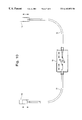
- FIG. 11 shows an installation variant of the drive system of the invention in the rear of a vehicle.
- the motor-vehicle hatchback hinge shown in FIGS. 1 through 5 comprises an affixation part 1 on which hinges a link 2 of a four-link hinge.
- the link 2 is affixed at its other end to a base plate 3 which also affixes the trunk door or the engine hood or the hatchback 12 .
- the base plate 3 furthermore is connected in articulating manner by another link 4 of the four-link hinge to the affixation part 1 .
- a power spring ie a pneumatic spring 5 is located between the affixation part 1 and the base plate 3 and is connected by the ball-joints 6 and 7 to the base plate 3 and the affixation part 1 .
- a push-pull cable 13 is used to drive the shifting mechanism 14 allowing shifting the connection point 6 of the pneumatic spring 5 up and down and back.
- connection points 6 and 7 of the pneumatic spring 5 are located on a straight line running approximately parallel to the hatchback 12 and as a result no force component in the open direction acts on the hatchback 12 .
- the orientation of the pneumatic spring 5 is changed in such manner that one force component shall act in the direction of opening.
- This feature is attained in the presently selected illustrative embodiment in that the connection point 6 of the pneumatic spring 5 initially is lowered by a drive further discussed below in the manner indicated by the arrow shown in FIG. 2 . It is assumes in this respect that when the connection point 6 is lowered as shown in FIG. 2, the force exerted by the pneumatic spring 5 is inadequate on account of its angular position relative to the hatchback or to the four-link hinge, to cause opening the hatchback.
- connection point 6 has been lowered so much that the angular position of the pneumatic spring 5 relative to the four-link hinge or to the hatchback 12 is adequate to overcome the system deadpoint and to initiate opening thee hatchback 12 .
- the pneumatic spring 5 therefore will relax and thereby the hatchback 12 will open in the direction of the curving arrow.
- connection point 6 In order to fully use the maximum force produced by the power spring, ie the pneumatic spring 5 , the connection point 6 will next be motor-raised again from its lowered position as indicated in FIG. 3 to an intermediate position as shown in FIG. 4 and into an end position as shown in FIG. 5 . The connection point 6 is again in its topmost position that it assumes in FIG. 1 . Thereby the spring 5 is able to apply its full force to open and keep open the hatchback 12 .
- connection point 6 of the power spring ie the pneumatic spring 5 in the lowered position shown in FIG. 3 in order to achieve full hatchback opening.
- the lowering of the connection point 6 shall be followed by a lifting it again as shown in FIGS. 4 and 5.
- FIG. 5 moreover shows the feasibility of the invention to initiate self-closing by the hatchback 12 .
- Such self-closing for instance may be implemented by relaxing the power spring, ie the pneumatic spring 5 by horizontally shifting the connection point 6 (in FIG. 5, to the left and in the vehicle to the rear, as shown in dashed lines), whereby the pneumatic spring 5 will subtend a more acute angle relative to the hatchback 12 .
- This escaping motion obviously may also be carried out in a direction other than that shown.
- the shown leftward shifting of the connection point 6 (straight arrow) is followed by a closing motion (curved arrow)
- the closed position of the body-side connection point 6 allowing to return it into its position of FIG. 1 without danger of reopening because no force component will act in this position in the direction of opening the closed hatchback 12 ; the hatchback 12 will not be opened, instead only the pneumatic spring 5 is restressed.
- connection point 6 illustratively can be implemented by a an adjusting system as shown in FIG. 10 in order that the connection points of the pneumatic springs 5 on each side of the hatchback 12 be equally adjusted by a single motor drive.
- FIG. 11 shows an illustrative variation of installation.
- the adjusting system of FIG. 10 shows the two shifting mechanisms 14 for the two connection points 6 of the pneumatic springs 5 . They are synchronously adjusted by the two push-pull cables 13 . The adjustment is carried out using a setting unit 15 in a housing 16 .
- the white arrows in FIG. 10 show the upward adjusting motion of the shifting mechanisms and the black arrows show the downward adjusting motion.
- the operation of the setting unit 15 is discussed more comprehensively in relation to FIGS. 6 through 9.
- the setting unit 15 (parts of housing 16 are shown) comprises a cam 8 which can be set into rotation as shown by the arrow of FIG. 6 by a motor and which in this selected embodiment is a lever linkage.
- the lever arms 9 and 10 are connected to the ends of the cam 8 and to the associated push-pull bars 11 of mechanical push-pull cables 13 .
- the push-pull cables 13 lead to the associated shifting mechanisms 14 for the connection points 6 of the pneumatic springs 5 .
- shifting mechanisms 14 are shown only in illustrative manner in the Figures and for instance may be guides guiding a slide connected to the particular push-pull cable, this slide bearing the connection point 6 , ie the ball-pin for the body-side affixation of the pneumatic spring 5 .
- the setting unit denoted overall by 15 is mounted inside the housing 16 which also receives the omitted drive motor.
- FIG. 6 shows a position of cam 8 which corresponds to an intermediate position of the body-side connection point 6 as shown in FIGS. 2 and 4.
- FIG. 8 shows the position of the cam 8 corresponding to the lower position of the connection point 6 in the shifting mechanism 14 of FIG. 3 .
- FIG. 11 shows a configuration of a drive-system of the invention. It comprises the pneumatic springs 5 keeping the hatchback 12 open.
- the drive system of the invention in this case consists of the setting unit 15 in the housing 16 and so driving the two adjusting mechanisms 14 by means of the push-pull cables 13 that the connection points 6 of the pneumatic springs 5 change their body-side positions.
Abstract
Description
Claims (13)
Applications Claiming Priority (2)
| Application Number | Priority Date | Filing Date | Title |
|---|---|---|---|
| DE19755486.6 | 1997-12-13 | ||
| DE19755486A DE19755486C5 (en) | 1997-12-13 | 1997-12-13 | Trunk lid actuation |
Publications (1)
| Publication Number | Publication Date |
|---|---|
| US6182952B1 true US6182952B1 (en) | 2001-02-06 |
Family
ID=7851824
Family Applications (1)
| Application Number | Title | Priority Date | Filing Date |
|---|---|---|---|
| US09/210,576 Expired - Fee Related US6182952B1 (en) | 1997-12-13 | 1998-12-14 | Acuator for a trunk-cover, a hood, a door, a rear door of vehicles, especially of automobiles |
Country Status (2)
| Country | Link |
|---|---|
| US (1) | US6182952B1 (en) |
| DE (1) | DE19755486C5 (en) |
Cited By (23)
| Publication number | Priority date | Publication date | Assignee | Title |
|---|---|---|---|---|
| US6382705B1 (en) * | 2001-02-01 | 2002-05-07 | General Motors Corporation | Vehicle independent rear access panel with four bar hinge |
| US6668962B2 (en) | 2001-05-18 | 2003-12-30 | Hyundai Motor Company | Hood hanging structure for a vehicle |
| US6719356B2 (en) | 2001-04-26 | 2004-04-13 | Litens Automotive | Powered opening mechanism and control system |
| US20040088826A1 (en) * | 2002-10-31 | 2004-05-13 | Edscha Ag | Vehicle hinge |
| US20040205934A1 (en) * | 2003-03-21 | 2004-10-21 | Lester Derbis | Activating mechanism for closures with four-link hinges |
| US20040262828A1 (en) * | 2003-06-24 | 2004-12-30 | Bauman Walter Douglas | Device to provide initial pop-up of an automotive deck lid via a gas spring |
| US20050168010A1 (en) * | 2001-04-26 | 2005-08-04 | Litens Automotive | Powered opening mechanism and control system |
| US6964316B1 (en) * | 1999-05-17 | 2005-11-15 | Edscha Ag | Front opening hood assembly |
| US20070035149A1 (en) * | 2005-08-01 | 2007-02-15 | Stabilus Gmbh | Hinge device with a piston/cylinder unit |
| US20070145774A1 (en) * | 2005-12-22 | 2007-06-28 | Richard Plavetich | Automotive door hinge |
| US20080115322A1 (en) * | 2006-11-22 | 2008-05-22 | Carlo Migli | Hinge with reduced bulkiness for vertical-movement doors |
| US20090202292A1 (en) * | 2008-02-08 | 2009-08-13 | Gm Global Technology Operations, Inc. | Multiple Position Ball Stud for Closure Strut |
| US20110035903A1 (en) * | 2009-08-11 | 2011-02-17 | Jeremy Thomas Sims | Hinge And Spring Assembly |
| US20120013143A1 (en) * | 2009-01-23 | 2012-01-19 | Brose Fahrzeugteile Gmbh & Co. Kg, Hallstadt | Drive configuration for the motorized displacement of a displacement element of a motor vehicle |
| US8721000B2 (en) | 2012-06-01 | 2014-05-13 | Steelcase Inc. | Seating system with multi-position backrest |
| US20150048651A1 (en) * | 2012-03-29 | 2015-02-19 | Audi Ag | Pedestrian protection device for a motor vehicle |
| TWI476068B (en) * | 2012-06-04 | 2015-03-11 | Hiwin Tech Corp | Multi-link discharging mechanism |
| US9057180B1 (en) * | 2011-05-02 | 2015-06-16 | The Charles Machine Works, Inc. | Apparatus for sealing a vacuum tank door |
| CN105564512A (en) * | 2014-10-29 | 2016-05-11 | 三菱自动车工业株式会社 | Charging lid device for vehicle |
| US9821953B2 (en) | 2011-05-02 | 2017-11-21 | The Charles Machine Works, Inc. | Apparatus for sealing a vacuum tank door |
| US10221602B2 (en) | 2016-04-06 | 2019-03-05 | The Charles Machine Works, Inc. | Vacuum system |
| USD895914S1 (en) | 2018-02-15 | 2020-09-08 | The Charles Machine Works, Inc. | Vacuum system |
| US11059682B2 (en) | 2017-12-21 | 2021-07-13 | The Charles Machine Works, Inc. | Offloading vacuum tank |
Families Citing this family (7)
| Publication number | Priority date | Publication date | Assignee | Title |
|---|---|---|---|---|
| DE10023288A1 (en) * | 2000-05-12 | 2001-11-29 | Daimler Chrysler Ag | Actuating arrangement for opening and closing swiveling vehicle wings |
| DE102004033037B4 (en) * | 2004-07-07 | 2017-12-21 | Volkswagen Ag | Hatch structure |
| DE102004057363B4 (en) * | 2004-11-27 | 2009-09-17 | Stabilus Gmbh | actuator |
| DE102006054855B4 (en) * | 2006-11-20 | 2013-07-04 | Faurecia Autositze Gmbh | Bowden cable system, in particular for a vehicle seat |
| DE102008017396B4 (en) * | 2008-04-05 | 2014-03-27 | Faurecia Autositze Gmbh | balancer |
| DE202010001670U1 (en) * | 2010-02-02 | 2011-06-09 | SCHERDEL INNOTEC Forschungs- und Entwicklungs-GmbH, 95615 | Device for closing a hinged flap and flap and motor vehicle with such a device |
| DE102011003282B4 (en) * | 2011-01-27 | 2015-08-27 | Scherdel Innotec Forschungs- Und Entwicklungs-Gmbh | Device for closing a pivotable flap of a motor vehicle |
Citations (5)
| Publication number | Priority date | Publication date | Assignee | Title |
|---|---|---|---|---|
| US4623132A (en) * | 1985-02-27 | 1986-11-18 | Fichtel & Sachs Industries, Inc. | Gas spring counterbalance system |
| US4833826A (en) * | 1987-04-03 | 1989-05-30 | Matra Automobile | Closure device having a hinged closure member |
| US5095654A (en) * | 1990-07-30 | 1992-03-17 | Eccleston Jon E | Automatic operating system for swinging door |
| DE29701617U1 (en) | 1996-02-01 | 1997-03-27 | Kuester & Co Gmbh | Actuation for trunk lid, bonnets, doors or the like. of vehicles, in particular motor vehicles |
| US5865497A (en) * | 1995-11-30 | 1999-02-02 | Stabilus Gmbh | Pneumatic strut for a motor vechicle |
Family Cites Families (4)
| Publication number | Priority date | Publication date | Assignee | Title |
|---|---|---|---|---|
| US4776626A (en) * | 1987-07-20 | 1988-10-11 | Perfection Spring & Stamping Corp. | Trunk lid hinge and spring assembly |
| DE19507426A1 (en) * | 1995-03-03 | 1996-09-05 | Bayerische Motoren Werke Ag | Mechanism for adjustment of flap, esp. tail flap of motor vehicle |
| DE19758130C2 (en) * | 1997-03-15 | 2001-07-19 | Suspa Holding Gmbh | Lifting unit, in particular for a cover that can be pivoted relative to a fixed part |
| DE29705372U1 (en) * | 1997-03-25 | 1997-05-28 | Kirchhoff Gmbh & Co | Device for opening a hood of a motor vehicle |
-
1997
- 1997-12-13 DE DE19755486A patent/DE19755486C5/en not_active Expired - Fee Related
-
1998
- 1998-12-14 US US09/210,576 patent/US6182952B1/en not_active Expired - Fee Related
Patent Citations (5)
| Publication number | Priority date | Publication date | Assignee | Title |
|---|---|---|---|---|
| US4623132A (en) * | 1985-02-27 | 1986-11-18 | Fichtel & Sachs Industries, Inc. | Gas spring counterbalance system |
| US4833826A (en) * | 1987-04-03 | 1989-05-30 | Matra Automobile | Closure device having a hinged closure member |
| US5095654A (en) * | 1990-07-30 | 1992-03-17 | Eccleston Jon E | Automatic operating system for swinging door |
| US5865497A (en) * | 1995-11-30 | 1999-02-02 | Stabilus Gmbh | Pneumatic strut for a motor vechicle |
| DE29701617U1 (en) | 1996-02-01 | 1997-03-27 | Kuester & Co Gmbh | Actuation for trunk lid, bonnets, doors or the like. of vehicles, in particular motor vehicles |
Cited By (38)
| Publication number | Priority date | Publication date | Assignee | Title |
|---|---|---|---|---|
| US6964316B1 (en) * | 1999-05-17 | 2005-11-15 | Edscha Ag | Front opening hood assembly |
| US6382705B1 (en) * | 2001-02-01 | 2002-05-07 | General Motors Corporation | Vehicle independent rear access panel with four bar hinge |
| US7070226B2 (en) | 2001-04-26 | 2006-07-04 | Litens Automotive | Powered opening mechanism and control system |
| US6719356B2 (en) | 2001-04-26 | 2004-04-13 | Litens Automotive | Powered opening mechanism and control system |
| US20050168010A1 (en) * | 2001-04-26 | 2005-08-04 | Litens Automotive | Powered opening mechanism and control system |
| US6668962B2 (en) | 2001-05-18 | 2003-12-30 | Hyundai Motor Company | Hood hanging structure for a vehicle |
| US20040088826A1 (en) * | 2002-10-31 | 2004-05-13 | Edscha Ag | Vehicle hinge |
| US7469447B2 (en) | 2002-10-31 | 2008-12-30 | Edscha Ag | Vehicle hinge |
| US20040205934A1 (en) * | 2003-03-21 | 2004-10-21 | Lester Derbis | Activating mechanism for closures with four-link hinges |
| US7137174B2 (en) * | 2003-03-21 | 2006-11-21 | Gecom Corp | Activating mechanism for closures with four-link hinges |
| US20040262828A1 (en) * | 2003-06-24 | 2004-12-30 | Bauman Walter Douglas | Device to provide initial pop-up of an automotive deck lid via a gas spring |
| US20070035149A1 (en) * | 2005-08-01 | 2007-02-15 | Stabilus Gmbh | Hinge device with a piston/cylinder unit |
| US7445267B2 (en) * | 2005-08-01 | 2008-11-04 | Stabilus Gmbh | Hinge device with a piston/cylinder unit |
| US20070145774A1 (en) * | 2005-12-22 | 2007-06-28 | Richard Plavetich | Automotive door hinge |
| US7328932B2 (en) | 2005-12-22 | 2008-02-12 | Nissan Design America, Inc. | Automotive door hinge |
| US20080115322A1 (en) * | 2006-11-22 | 2008-05-22 | Carlo Migli | Hinge with reduced bulkiness for vertical-movement doors |
| US8082629B2 (en) * | 2006-11-22 | 2011-12-27 | Agostino Ferrari S.P.A. | Hinge with reduced bulkiness for vertical-movement doors |
| US8056183B2 (en) | 2008-02-08 | 2011-11-15 | GM Global Technology Operations LLC | Multiple position ball stud for closure strut |
| US20090202292A1 (en) * | 2008-02-08 | 2009-08-13 | Gm Global Technology Operations, Inc. | Multiple Position Ball Stud for Closure Strut |
| US9080366B2 (en) * | 2009-01-23 | 2015-07-14 | Brose Fahrzeugteile Gmbh & Co. Kg, Hallstadt | Drive configuration for the motorized displacement of a displacement element of a motor vehicle |
| US20120013143A1 (en) * | 2009-01-23 | 2012-01-19 | Brose Fahrzeugteile Gmbh & Co. Kg, Hallstadt | Drive configuration for the motorized displacement of a displacement element of a motor vehicle |
| US8205299B2 (en) * | 2009-08-11 | 2012-06-26 | Deere & Company | Hinge and spring assembly |
| US20110035903A1 (en) * | 2009-08-11 | 2011-02-17 | Jeremy Thomas Sims | Hinge And Spring Assembly |
| US10207863B2 (en) | 2011-05-02 | 2019-02-19 | The Charles Machine Works, Inc. | Apparatus for sealing a vacuum tank door |
| US9821953B2 (en) | 2011-05-02 | 2017-11-21 | The Charles Machine Works, Inc. | Apparatus for sealing a vacuum tank door |
| US9057180B1 (en) * | 2011-05-02 | 2015-06-16 | The Charles Machine Works, Inc. | Apparatus for sealing a vacuum tank door |
| US9308885B2 (en) * | 2012-03-29 | 2016-04-12 | Audi Ag | Pedestrian protection device for a motor vehicle |
| US20150048651A1 (en) * | 2012-03-29 | 2015-02-19 | Audi Ag | Pedestrian protection device for a motor vehicle |
| US9259089B2 (en) | 2012-06-01 | 2016-02-16 | Steelcase Inc. | Seating system with multi-position backrest |
| US9700148B2 (en) | 2012-06-01 | 2017-07-11 | Steelcase Inc. | Seating system with multi-position backrest |
| US8721000B2 (en) | 2012-06-01 | 2014-05-13 | Steelcase Inc. | Seating system with multi-position backrest |
| TWI476068B (en) * | 2012-06-04 | 2015-03-11 | Hiwin Tech Corp | Multi-link discharging mechanism |
| CN105564512A (en) * | 2014-10-29 | 2016-05-11 | 三菱自动车工业株式会社 | Charging lid device for vehicle |
| US10221602B2 (en) | 2016-04-06 | 2019-03-05 | The Charles Machine Works, Inc. | Vacuum system |
| US10538949B2 (en) | 2016-04-06 | 2020-01-21 | The Charles Machine Works, Inc. | Vacuum system |
| US11059682B2 (en) | 2017-12-21 | 2021-07-13 | The Charles Machine Works, Inc. | Offloading vacuum tank |
| US11858761B2 (en) | 2017-12-21 | 2024-01-02 | The Charles Machine Works, Inc. | Offloading vacuum tank |
| USD895914S1 (en) | 2018-02-15 | 2020-09-08 | The Charles Machine Works, Inc. | Vacuum system |
Also Published As
| Publication number | Publication date |
|---|---|
| DE19755486A1 (en) | 1999-06-24 |
| DE19755486C2 (en) | 2001-07-19 |
| DE19755486C5 (en) | 2006-10-05 |
Similar Documents
| Publication | Publication Date | Title |
|---|---|---|
| US6182952B1 (en) | Acuator for a trunk-cover, a hood, a door, a rear door of vehicles, especially of automobiles | |
| US7293819B2 (en) | Decklid hinge with motor to automate opening and closing | |
| US7137174B2 (en) | Activating mechanism for closures with four-link hinges | |
| EP1221523B1 (en) | Vehicle with a vehicle liftgate power operating system | |
| EP1306512B1 (en) | An actuator assembly | |
| US6325445B1 (en) | Motor vehicle with a body | |
| US7766411B2 (en) | Adjusting mechanism of a soft top compartment cover of a convertible | |
| US7322635B2 (en) | Cover device for the vehicle top storage compartment of a convertible vehicle | |
| US20030136054A1 (en) | Rod on rail power liftgate drive mechansism | |
| US6568495B1 (en) | Automotive vehicle hood system | |
| EP1247675A1 (en) | Wing opening and closing device for truck | |
| US6405486B1 (en) | Vehicle liftgate power operating system | |
| US6637157B1 (en) | Vehicle liftgate power operating system | |
| US7469447B2 (en) | Vehicle hinge | |
| CN113107295B (en) | Scissor door hinge mechanism and vehicle | |
| CN101023236B (en) | Floor lock | |
| KR20060113536A (en) | Vehicle with tail gate | |
| US20050264029A1 (en) | Strut and hinge assembly for vehicle | |
| US6820916B2 (en) | Actuating device for the folding roof of a motor vehicle | |
| US20040040213A1 (en) | Controlled counter balance actuator for a lift-gate | |
| US7604283B2 (en) | Cabriolet | |
| JP5631189B2 (en) | Operation mechanism and lock mechanism for vehicle cover | |
| CN212716270U (en) | Back door hinge mechanism and car | |
| EP1391578A3 (en) | Heavy duty friction stay for openable member | |
| JP5645639B2 (en) | Bearings for vehicle covers |
Legal Events
| Date | Code | Title | Description |
|---|---|---|---|
| AS | Assignment |
Owner name: KUSTER & CO. GMBH, ENGLAND Free format text: ASSIGNMENT OF ASSIGNORS INTEREST;ASSIGNOR:GUTIERREZ, CARMELO;REEL/FRAME:009913/0098 Effective date: 19990301 |
|
| AS | Assignment |
Owner name: KUSTER & CO. GMBH, GERMANY Free format text: CORRECTIVE ASSIGNMENT TO CORRECT THE STATE/COUNTRY CODE PREVIOUSLY RECORDED ON REEL 9913 AND FRAME 0098;ASSIGNOR:GUTIERREZ, CARMELO;REEL/FRAME:010638/0425 Effective date: 19990301 |
|
| FEPP | Fee payment procedure |
Free format text: PAYOR NUMBER ASSIGNED (ORIGINAL EVENT CODE: ASPN); ENTITY STATUS OF PATENT OWNER: LARGE ENTITY |
|
| FEPP | Fee payment procedure |
Free format text: PAYER NUMBER DE-ASSIGNED (ORIGINAL EVENT CODE: RMPN); ENTITY STATUS OF PATENT OWNER: LARGE ENTITY Free format text: PAYOR NUMBER ASSIGNED (ORIGINAL EVENT CODE: ASPN); ENTITY STATUS OF PATENT OWNER: LARGE ENTITY |
|
| FPAY | Fee payment |
Year of fee payment: 4 |
|
| REMI | Maintenance fee reminder mailed | ||
| LAPS | Lapse for failure to pay maintenance fees | ||
| STCH | Information on status: patent discontinuation |
Free format text: PATENT EXPIRED DUE TO NONPAYMENT OF MAINTENANCE FEES UNDER 37 CFR 1.362 |
|
| FP | Lapsed due to failure to pay maintenance fee |
Effective date: 20090206 |