US6187000B1 - Cannula for receiving surgical instruments - Google Patents
Cannula for receiving surgical instruments Download PDFInfo
- Publication number
- US6187000B1 US6187000B1 US09/137,335 US13733598A US6187000B1 US 6187000 B1 US6187000 B1 US 6187000B1 US 13733598 A US13733598 A US 13733598A US 6187000 B1 US6187000 B1 US 6187000B1
- Authority
- US
- United States
- Prior art keywords
- passage
- tubular portion
- cannula
- distal end
- surgical instruments
- Prior art date
- Legal status (The legal status is an assumption and is not a legal conclusion. Google has not performed a legal analysis and makes no representation as to the accuracy of the status listed.)
- Expired - Lifetime
Links
Images

Classifications
-
- A—HUMAN NECESSITIES
- A61—MEDICAL OR VETERINARY SCIENCE; HYGIENE
- A61B—DIAGNOSIS; SURGERY; IDENTIFICATION
- A61B17/00—Surgical instruments, devices or methods, e.g. tourniquets
- A61B17/34—Trocars; Puncturing needles
- A61B17/3417—Details of tips or shafts, e.g. grooves, expandable, bendable; Multiple coaxial sliding cannulas, e.g. for dilating
- A61B17/3421—Cannulas
-
- A—HUMAN NECESSITIES
- A61—MEDICAL OR VETERINARY SCIENCE; HYGIENE
- A61B—DIAGNOSIS; SURGERY; IDENTIFICATION
- A61B17/00—Surgical instruments, devices or methods, e.g. tourniquets
- A61B17/02—Surgical instruments, devices or methods, e.g. tourniquets for holding wounds open; Tractors
- A61B17/0218—Surgical instruments, devices or methods, e.g. tourniquets for holding wounds open; Tractors for minimally invasive surgery
-
- A—HUMAN NECESSITIES
- A61—MEDICAL OR VETERINARY SCIENCE; HYGIENE
- A61B—DIAGNOSIS; SURGERY; IDENTIFICATION
- A61B17/00—Surgical instruments, devices or methods, e.g. tourniquets
- A61B17/16—Bone cutting, breaking or removal means other than saws, e.g. Osteoclasts; Drills or chisels for bones; Trepans
- A61B17/17—Guides or aligning means for drills, mills, pins or wires
- A61B17/1739—Guides or aligning means for drills, mills, pins or wires specially adapted for particular parts of the body
- A61B17/1757—Guides or aligning means for drills, mills, pins or wires specially adapted for particular parts of the body for the spine
-
- A—HUMAN NECESSITIES
- A61—MEDICAL OR VETERINARY SCIENCE; HYGIENE
- A61B—DIAGNOSIS; SURGERY; IDENTIFICATION
- A61B17/00—Surgical instruments, devices or methods, e.g. tourniquets
- A61B17/32—Surgical cutting instruments
- A61B17/320016—Endoscopic cutting instruments, e.g. arthroscopes, resectoscopes
- A61B17/32002—Endoscopic cutting instruments, e.g. arthroscopes, resectoscopes with continuously rotating, oscillating or reciprocating cutting instruments
-
- A—HUMAN NECESSITIES
- A61—MEDICAL OR VETERINARY SCIENCE; HYGIENE
- A61B—DIAGNOSIS; SURGERY; IDENTIFICATION
- A61B17/00—Surgical instruments, devices or methods, e.g. tourniquets
- A61B17/34—Trocars; Puncturing needles
- A61B17/3417—Details of tips or shafts, e.g. grooves, expandable, bendable; Multiple coaxial sliding cannulas, e.g. for dilating
- A61B17/3421—Cannulas
- A61B17/3439—Cannulas with means for changing the inner diameter of the cannula, e.g. expandable
-
- A—HUMAN NECESSITIES
- A61—MEDICAL OR VETERINARY SCIENCE; HYGIENE
- A61B—DIAGNOSIS; SURGERY; IDENTIFICATION
- A61B17/00—Surgical instruments, devices or methods, e.g. tourniquets
- A61B17/02—Surgical instruments, devices or methods, e.g. tourniquets for holding wounds open; Tractors
- A61B17/0293—Surgical instruments, devices or methods, e.g. tourniquets for holding wounds open; Tractors with ring member to support retractor elements
-
- A—HUMAN NECESSITIES
- A61—MEDICAL OR VETERINARY SCIENCE; HYGIENE
- A61B—DIAGNOSIS; SURGERY; IDENTIFICATION
- A61B17/00—Surgical instruments, devices or methods, e.g. tourniquets
- A61B17/16—Bone cutting, breaking or removal means other than saws, e.g. Osteoclasts; Drills or chisels for bones; Trepans
- A61B17/17—Guides or aligning means for drills, mills, pins or wires
- A61B17/1735—Guides or aligning means for drills, mills, pins or wires for rasps or chisels
-
- A—HUMAN NECESSITIES
- A61—MEDICAL OR VETERINARY SCIENCE; HYGIENE
- A61B—DIAGNOSIS; SURGERY; IDENTIFICATION
- A61B17/00—Surgical instruments, devices or methods, e.g. tourniquets
- A61B17/28—Surgical forceps
- A61B17/2812—Surgical forceps with a single pivotal connection
- A61B17/282—Jaws
-
- A—HUMAN NECESSITIES
- A61—MEDICAL OR VETERINARY SCIENCE; HYGIENE
- A61B—DIAGNOSIS; SURGERY; IDENTIFICATION
- A61B17/00—Surgical instruments, devices or methods, e.g. tourniquets
- A61B17/28—Surgical forceps
- A61B17/29—Forceps for use in minimally invasive surgery
-
- A—HUMAN NECESSITIES
- A61—MEDICAL OR VETERINARY SCIENCE; HYGIENE
- A61B—DIAGNOSIS; SURGERY; IDENTIFICATION
- A61B17/00—Surgical instruments, devices or methods, e.g. tourniquets
- A61B17/32—Surgical cutting instruments
- A61B17/320016—Endoscopic cutting instruments, e.g. arthroscopes, resectoscopes
-
- A—HUMAN NECESSITIES
- A61—MEDICAL OR VETERINARY SCIENCE; HYGIENE
- A61B—DIAGNOSIS; SURGERY; IDENTIFICATION
- A61B17/00—Surgical instruments, devices or methods, e.g. tourniquets
- A61B17/00234—Surgical instruments, devices or methods, e.g. tourniquets for minimally invasive surgery
- A61B2017/00238—Type of minimally invasive operation
- A61B2017/00261—Discectomy
-
- A—HUMAN NECESSITIES
- A61—MEDICAL OR VETERINARY SCIENCE; HYGIENE
- A61B—DIAGNOSIS; SURGERY; IDENTIFICATION
- A61B17/00—Surgical instruments, devices or methods, e.g. tourniquets
- A61B2017/0046—Surgical instruments, devices or methods, e.g. tourniquets with a releasable handle; with handle and operating part separable
Definitions
- the present invention is directed to a cannula for receiving surgical instruments for performing a surgical procedure on a body.
- Endoscopic surgical techniques allow a surgical procedure to be performed on a patient's body through a relatively small incision in the body and with a limited amount of body tissue disruption.
- Endoscopic surgery typically utilizes a tubular structure known as a cannula which is inserted into a small incision in the body.
- the cannula holds the incision open and serves as a conduit extending between the exterior of the body and the local area inside the body where the surgery is to be performed.
- the present invention is a cannula for receiving surgical instruments for performing a surgical procedure on a body.
- the cannula comprises a tube structure defining a passage through which the surgical instruments are inserted into the body.
- the tube structure has a proximal end and a distal end.
- the tube structure includes an expandable portion for enabling an increase in the cross-sectional area of the passage at least at the distal end.
- the expandable portion of the tube structure when expanded, has a conical configuration.
- the expandable portion of the tube structure includes an arcuate slot and a guide pin disposed in the arcuate slot.
- the guide pin is movable from a terminal end of the slot to a second terminal end of the slot to enable the cross-sectional area of the passage at the distal end to increase.
- the tube structure includes first and second tubular portions attached to one another.
- the second tubular portion comprises the expandable portion.
- the first tubular portion comprises a length of stainless steel tubing and the second tubular portion comprises an arcuate segment of stainless steel sheet stock rolled into a tubular shape.
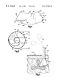
- FIG. 1 is an exploded perspective view of a surgical cannula constructed in accordance with the present invention, the cannula being shown in an expanded condition;
- FIG. 2 is a perspective view of the cannula of FIG. 1 with parts removed for clarity, the cannula being shown in a contracted condition;
- FIG. 3 is a schematic end view showing the cannula of FIG. 1 in the expanded position
- FIG. 4 is a roll out view of a part of the cannula of FIG. 1;
- FIG. 5 is a schematic sectional view of the cannula of FIG. 1 during a surgical procedure.
- the present invention is directed to a cannula for receiving surgical instruments for performing a surgical procedure on the body of a patient.
- the present invention is applicable to a variety of surgical procedures in which endoscopic surgical techniques are used.
- FIG. 1 illustrates a cannula 10 constructed according to the present invention.
- the cannula 10 is a tubular structure 12 centered on an axis 14 .
- the tubular structure 12 defines a passage 16 through the cannula 10 .
- Surgical instruments are inserted into the body during endoscopic surgery through the passage 16 .
- the tubular structure 12 comprises a first tubular portion 20 and a second tubular portion 40 attached to the first tubular portion.
- the first tubular portion 20 is preferably made of a length of stainless steel tubing, but could alternatively be made of another suitable material.
- the first tubular portion 20 has a proximal end 22 and a distal end 24 .
- Parallel cylindrical inner and outer surfaces 26 and 28 respectively, extend between the ends 22 , 24 of the first tubular portion 20 .
- the inner surface 26 defines a first passage portion 30 of the passage 16 through the cannula 10 .
- the first passage portion 30 has a diameter D 1 which is preferably in the range from 10 mm to 20 mm.
- the second tubular portion 40 of the tubular structure 12 is attached to the distal end 24 of the first tubular portion 20 .
- the second tubular portion is preferably made from stainless steel, but could alternatively be made from another suitable material.
- the second tubular portion 40 comprises an arcuate segment 42 of sheet stock.
- the arcuate segment 42 includes first and second arcuate edges 44 and 46 , respectively, and first and second planar edges 48 and 50 , respectively.
- the first and second planar edges 48 and 50 are rolled in an overlapping manner to form the tubular configuration of the second tubular portion 40 .
- first and second arcuate edges 44 and 46 define oppositely disposed first and second ends 60 and 62 (FIGS. 1 and 2 ), respectively, of the second tubular portion.
- the first and second ends 60 and 62 are connected by a central portion 64 .
- the first end 60 of the second tubular portion 40 is attached to the distal end 24 of the first tubular portion 20 by a single fastener, such as a rivet 66 .
- the rivet 66 extends through two aligned apertures 68 (FIG. 4) at the first end 60 of the second tubular portion 40 .
- the first end 60 of the second tubular portion 40 is pivotable about the rivet 66 .
- the second tubular portion 40 includes parallel inner and outer surfaces 70 and 72 (FIGS. 1 and 2 ), respectively, extending between the first and second ends 60 and 62 .
- the inner surface 70 defines a second passage portion 74 of the passage 16 through the cannula 10 which extends as a continuation of the first passage portion 30 in the first tubular portion 20 .
- An arcuate slot 80 is formed in the second tubular portion 40 and extends between the inner and outer surfaces 70 and 72 of the second tubular portion.
- the arcuate slot 80 extends along a curvilinear path in the central portion 64 of the second tubular portion 40 toward the second end 60 of the second tubular portion.
- the arcuate slot 80 has a first terminal end 82 located in the central portion 64 of the second tubular portion 40 .
- a second terminal end 84 of the arcuate slot 80 is located adjacent the intersection of the second arcuate edge 46 and the first planar edge 48 of the arcuate segment 42 .
- a guide pin 90 is attached to the inner surface 70 of the second tubular portion 40 adjacent the intersection of the second arcuate edge 46 and the second planar edge 50 .
- the guide pin 90 In the tubular configuration of the second tubular portion 40 , the guide pin 90 is located in the arcuate slot 80 and is movable along the curvilinear path of the arcuate slot.
- a washer 92 is secured an inner end of the guide pin 90 to retain the guide pin in the arcuate slot 80 .
- the second tubular portion 40 of the tubular structure 12 is expandable from a contracted condition shown in FIG. 2 to an expanded condition shown in FIG. 1 .
- the guide pin 90 is located in the first terminal end 82 of the arcuate slot 80 in the second tubular portion 40 and the second passage portion 74 defined by the second tubular portion is cylindrical in shape.
- the second passage 74 has a generally constant diameter D 2 (FIGS. 2 and 3) which is approximately equal to the diameter D 1 of the first tubular portion 20 .
- the cross-sectional area of the second passage portion 74 at the second end 62 of the second tubular portion 40 which is function of the diameter D 2 , is approximately the same as the cross-sectional area at the first end 60 of the second tubular portion and is approximately the same as the cross-sectional area of the first passage portion 30 in the first tubular portion 20 .
- the guide pin 90 is located in the second terminal end 84 of the arcuate slot 80 in the second tubular portion 40 and the second tubular portion has a conical configuration.
- the second passage portion 74 has a diameter D 3 (FIG. 3) which is larger then the diameter D 2 of the second passage portion at the first end 60 .
- the diameter D 3 of the second passage portion 74 at the second end 62 of the second tubular portion is 40% to 80% greater than the diameter D 1 of the second passage portion at the first end 60 .
- the cross-sectional area of the second passage portion 74 at the second end 62 of the second tubular portion 40 which is function of the diameter D 3 , is 40% to 80% greater than the cross-sectional area of the second passage portion at the first end 60 of the second tubular portion.
- the cannula 10 includes an outer layer 100 (FIG. 1) for maintaining the second tubular portion 40 of the cannula in the contracted condition. It is contemplated that other suitable means for maintaining the second tubular portion 40 in the contracted condition could be employed.
- the outer layer 100 comprises a section of plastic tubing 102 which is heat shrunk over both the first and second tubular portions 20 and 40 to hold the second tubular portion in the contracted condition.
- a loop of nylon string 104 for tearing the heat shrunk tubing 102 is wrapped around the heat shrunk tubing so that it extends both underneath and on top of the tubing.
- An outer end 106 of the string 104 extends beyond the tubing 102 .
- the cannula 10 further includes an actuatable device 110 for expanding the second tubular portion 40 from the contracted condition to the expanded condition.
- the actuatable device 110 comprises a manually operated expansion tool 112 .
- the expansion tool 112 resembles a common pair of scissors and has a pair of legs 114 pivotally connected to one another.
- the expansion tool 112 includes a frustoconical end section 116 formed by a pair of frustoconical halves 118 . Each of the frustoconical halves 118 extends from a respective one of the legs 114 of the expansion tool 112 .
- suitable means for expanding the second tubular portion 40 toward the expanded condition could be employed, such as an inflatable balloon (not shown).
- the cannula 10 is inserted into the body of a patient in the contracted condition.
- the outer end 106 of the string 104 is then manually pulled on by the surgeon. Pulling on the string 104 tears the heat shrunk tubing 102 which is then removed from the cannula 10 by the surgeon. With the heat shrink tubing 102 removed, the second tubular portion 40 of the cannula 10 is thereby released for expansion toward the expanded condition.
- the expansion tool 112 is inserted into the passage 16 in the cannula 10 until the frustoconical end section 114 is located at the second end 62 of the second tubular portion 40 .
- the legs 114 of the expansion tool 112 are manually separated, causing the frustoconical halves 118 to separate also.
- a radially outward directed force is exerted on the inner surface 70 of the second tubular portion 40 by the halves 118 , causing the second tubular portion to expand toward the expanded condition.
- the guide pin 90 slides from the first terminal end 82 of the arcuate slot 80 to the second terminal end 84 of the arcuate slot to permit the expansion of the second tubular portion 40 .
- the expansion tool 112 can be rotated about the axis 14 to ensure that the second tubular portion 40 of the cannula 10 is completely expanded to the expanded condition.
- the expansion tool 112 is then collapsed and removed so that one or more surgical instruments (indicated schematically at 120 in FIG. 5) can be received through the cannula 10 and inserted into a patient's body 130 .
- the expandable second tubular portion 40 of the cannula 10 provides a significantly larger working area for the surgeon inside the body 130 within the confines of the cannula.
- endoscopic surgical instruments including but not limited to steerable instruments, shavers, dissectors, scissors, forceps, retractors, dilators, and video cameras, is made possible by the expandable cannula 10 .
- cannula 10 described herein could be the centerpiece of a endoscopic surgical kit which would include an assortment of surgical instruments designed and/or selected for use with the cannula.
Abstract
Description
Claims (22)
Priority Applications (24)
| Application Number | Priority Date | Filing Date | Title |
|---|---|---|---|
| US09/137,335 US6187000B1 (en) | 1998-08-20 | 1998-08-20 | Cannula for receiving surgical instruments |
| DE69942264T DE69942264D1 (en) | 1998-08-20 | 1999-06-17 | Sleeve for insertion of surgical instruments |
| EP99111083A EP0980677B1 (en) | 1998-08-20 | 1999-06-17 | Cannula for receiving surgical instruments |
| JP23441399A JP3145366B2 (en) | 1998-08-20 | 1999-08-20 | Cannula for receiving surgical instruments |
| JP2000315578A JP4201477B2 (en) | 1998-08-20 | 2000-10-16 | Cannula for receiving surgical instruments |
| US09/772,605 US6800084B2 (en) | 1998-08-20 | 2001-01-30 | Method for performing a surgical procedure and a cannula for use in performing the surgical procedure |
| US09/906,463 US6652553B2 (en) | 1998-08-20 | 2001-07-16 | Surgical tool for use in expanding a cannula |
| US10/514,797 US7799036B2 (en) | 1998-08-20 | 2001-07-31 | Method and apparatus for securing vertebrae |
| US10/435,730 US6811558B2 (en) | 1998-08-20 | 2003-05-09 | Method for performing a surgical procedure and a cannula for use in performing the surgical procedure |
| US10/440,278 US7108705B2 (en) | 1998-08-20 | 2003-05-16 | Cannula for receiving surgical instruments |
| US10/439,979 US7033369B2 (en) | 1998-08-20 | 2003-05-16 | Cannula for receiving surgical instruments |
| US10/441,319 US7670354B2 (en) | 1998-08-20 | 2003-05-16 | Cannula for receiving surgical instruments |
| US10/440,002 US7001397B2 (en) | 1998-08-20 | 2003-05-16 | Cannula for receiving surgical instruments |
| US10/439,385 US6837891B2 (en) | 1998-08-20 | 2003-05-16 | Cannula for receiving surgical instruments |
| US10/440,231 US7223278B2 (en) | 1998-08-20 | 2003-05-16 | Cannula for receiving surgical instruments |
| US10/665,754 US7682370B2 (en) | 1998-08-20 | 2003-09-19 | Surgical tool for use in expanding a cannula |
| US10/685,761 US7641670B2 (en) | 1998-08-20 | 2003-10-15 | Cannula for receiving surgical instruments |
| US10/713,820 US7985237B2 (en) | 1998-08-20 | 2003-11-14 | Cannula for receiving surgical instruments |
| US10/958,505 US7674273B2 (en) | 1998-08-20 | 2004-10-05 | Method for performing a surgical procedure and a cannula for use in performing the surgical procedure |
| US11/417,616 US8317817B2 (en) | 1998-08-20 | 2006-05-03 | Cannula for receiving surgical instruments |
| US11/417,646 US7892249B2 (en) | 1998-08-20 | 2006-05-03 | Cannula for receiving surgical instruments |
| US11/417,653 US7892171B2 (en) | 1998-08-20 | 2006-05-03 | Cannula for receiving surgical instruments |
| US13/615,961 US8540746B2 (en) | 1998-08-20 | 2012-09-14 | Cannula for receiving surgical instruments |
| US14/030,669 US8968351B2 (en) | 1998-08-20 | 2013-09-18 | Cannula for receiving surgical instruments |
Applications Claiming Priority (1)
| Application Number | Priority Date | Filing Date | Title |
|---|---|---|---|
| US09/137,335 US6187000B1 (en) | 1998-08-20 | 1998-08-20 | Cannula for receiving surgical instruments |
Related Child Applications (2)
| Application Number | Title | Priority Date | Filing Date |
|---|---|---|---|
| US09/772,605 Continuation-In-Part US6800084B2 (en) | 1998-08-20 | 2001-01-30 | Method for performing a surgical procedure and a cannula for use in performing the surgical procedure |
| US09/775,605 Continuation-In-Part US20010027008A1 (en) | 1998-08-20 | 2001-02-05 | Method for forming interconnect structure in semiconductor device |
Publications (1)
| Publication Number | Publication Date |
|---|---|
| US6187000B1 true US6187000B1 (en) | 2001-02-13 |
Family
ID=22476928
Family Applications (16)
| Application Number | Title | Priority Date | Filing Date |
|---|---|---|---|
| US09/137,335 Expired - Lifetime US6187000B1 (en) | 1998-08-20 | 1998-08-20 | Cannula for receiving surgical instruments |
| US09/772,605 Expired - Lifetime US6800084B2 (en) | 1998-08-20 | 2001-01-30 | Method for performing a surgical procedure and a cannula for use in performing the surgical procedure |
| US10/435,730 Expired - Lifetime US6811558B2 (en) | 1998-08-20 | 2003-05-09 | Method for performing a surgical procedure and a cannula for use in performing the surgical procedure |
| US10/440,002 Expired - Lifetime US7001397B2 (en) | 1998-08-20 | 2003-05-16 | Cannula for receiving surgical instruments |
| US10/440,231 Expired - Lifetime US7223278B2 (en) | 1998-08-20 | 2003-05-16 | Cannula for receiving surgical instruments |
| US10/439,979 Expired - Lifetime US7033369B2 (en) | 1998-08-20 | 2003-05-16 | Cannula for receiving surgical instruments |
| US10/439,385 Expired - Lifetime US6837891B2 (en) | 1998-08-20 | 2003-05-16 | Cannula for receiving surgical instruments |
| US10/440,278 Expired - Lifetime US7108705B2 (en) | 1998-08-20 | 2003-05-16 | Cannula for receiving surgical instruments |
| US10/441,319 Expired - Fee Related US7670354B2 (en) | 1998-08-20 | 2003-05-16 | Cannula for receiving surgical instruments |
| US10/713,820 Expired - Fee Related US7985237B2 (en) | 1998-08-20 | 2003-11-14 | Cannula for receiving surgical instruments |
| US10/958,505 Expired - Fee Related US7674273B2 (en) | 1998-08-20 | 2004-10-05 | Method for performing a surgical procedure and a cannula for use in performing the surgical procedure |
| US11/417,616 Expired - Lifetime US8317817B2 (en) | 1998-08-20 | 2006-05-03 | Cannula for receiving surgical instruments |
| US11/417,653 Expired - Lifetime US7892171B2 (en) | 1998-08-20 | 2006-05-03 | Cannula for receiving surgical instruments |
| US11/417,646 Expired - Fee Related US7892249B2 (en) | 1998-08-20 | 2006-05-03 | Cannula for receiving surgical instruments |
| US13/615,961 Expired - Lifetime US8540746B2 (en) | 1998-08-20 | 2012-09-14 | Cannula for receiving surgical instruments |
| US14/030,669 Expired - Fee Related US8968351B2 (en) | 1998-08-20 | 2013-09-18 | Cannula for receiving surgical instruments |
Family Applications After (15)
| Application Number | Title | Priority Date | Filing Date |
|---|---|---|---|
| US09/772,605 Expired - Lifetime US6800084B2 (en) | 1998-08-20 | 2001-01-30 | Method for performing a surgical procedure and a cannula for use in performing the surgical procedure |
| US10/435,730 Expired - Lifetime US6811558B2 (en) | 1998-08-20 | 2003-05-09 | Method for performing a surgical procedure and a cannula for use in performing the surgical procedure |
| US10/440,002 Expired - Lifetime US7001397B2 (en) | 1998-08-20 | 2003-05-16 | Cannula for receiving surgical instruments |
| US10/440,231 Expired - Lifetime US7223278B2 (en) | 1998-08-20 | 2003-05-16 | Cannula for receiving surgical instruments |
| US10/439,979 Expired - Lifetime US7033369B2 (en) | 1998-08-20 | 2003-05-16 | Cannula for receiving surgical instruments |
| US10/439,385 Expired - Lifetime US6837891B2 (en) | 1998-08-20 | 2003-05-16 | Cannula for receiving surgical instruments |
| US10/440,278 Expired - Lifetime US7108705B2 (en) | 1998-08-20 | 2003-05-16 | Cannula for receiving surgical instruments |
| US10/441,319 Expired - Fee Related US7670354B2 (en) | 1998-08-20 | 2003-05-16 | Cannula for receiving surgical instruments |
| US10/713,820 Expired - Fee Related US7985237B2 (en) | 1998-08-20 | 2003-11-14 | Cannula for receiving surgical instruments |
| US10/958,505 Expired - Fee Related US7674273B2 (en) | 1998-08-20 | 2004-10-05 | Method for performing a surgical procedure and a cannula for use in performing the surgical procedure |
| US11/417,616 Expired - Lifetime US8317817B2 (en) | 1998-08-20 | 2006-05-03 | Cannula for receiving surgical instruments |
| US11/417,653 Expired - Lifetime US7892171B2 (en) | 1998-08-20 | 2006-05-03 | Cannula for receiving surgical instruments |
| US11/417,646 Expired - Fee Related US7892249B2 (en) | 1998-08-20 | 2006-05-03 | Cannula for receiving surgical instruments |
| US13/615,961 Expired - Lifetime US8540746B2 (en) | 1998-08-20 | 2012-09-14 | Cannula for receiving surgical instruments |
| US14/030,669 Expired - Fee Related US8968351B2 (en) | 1998-08-20 | 2013-09-18 | Cannula for receiving surgical instruments |
Country Status (4)
| Country | Link |
|---|---|
| US (16) | US6187000B1 (en) |
| EP (1) | EP0980677B1 (en) |
| JP (2) | JP3145366B2 (en) |
| DE (1) | DE69942264D1 (en) |
Cited By (173)
| Publication number | Priority date | Publication date | Assignee | Title |
|---|---|---|---|---|
| US6524320B2 (en) * | 2001-05-15 | 2003-02-25 | Endius Incorporated | Cannula for receiving surgical instruments |
| US6530880B2 (en) | 2001-03-29 | 2003-03-11 | Endius Incorporated | Apparatus for supporting an endoscope |
| US20030073998A1 (en) * | 2000-08-01 | 2003-04-17 | Endius Incorporated | Method of securing vertebrae |
| US6589214B2 (en) | 2000-12-06 | 2003-07-08 | Rex Medical, L.P. | Vascular introducer sheath with retainer |
| US20030153927A1 (en) * | 2001-05-15 | 2003-08-14 | Endius Incorporated | Structure for receiving surgical instruments |
| US20030191371A1 (en) * | 2002-04-05 | 2003-10-09 | Smith Maurice M. | Devices and methods for percutaneous tissue retraction and surgery |
| US20030195549A1 (en) * | 1998-08-20 | 2003-10-16 | Davison Thomas W. | Cannula for receiving surgical instruments |
| US20030195518A1 (en) * | 2000-02-16 | 2003-10-16 | Cragg Andrew H. | Methods and apparatus for performing therapeutic procedures in the spine |
| US20030204189A1 (en) * | 2000-02-16 | 2003-10-30 | Cragg Andrew H. | Axial spinal implant and method and apparatus for implanting an axial spinal implant within the vertebrae of the spine |
| US6652553B2 (en) | 1998-08-20 | 2003-11-25 | Endius Incorporated | Surgical tool for use in expanding a cannula |
| US20030229353A1 (en) * | 2000-02-16 | 2003-12-11 | Cragg Andrew H. | Method and apparatus for providing posterior or anterior trans-sacral access to spinal vertebrae |
| US20030236529A1 (en) * | 2002-06-24 | 2003-12-25 | Endius Incorporated | Surgical instrument for moving vertebrae |
| WO2004021899A1 (en) * | 2002-09-05 | 2004-03-18 | Endius Incorporated | System and methods for performing minimally-invasive surgical procedures |
| WO2004039235A2 (en) * | 2002-10-25 | 2004-05-13 | Endius Incorporated | Apparatus and methods for shielding body structures during surgery |
| US6740090B1 (en) | 2000-02-16 | 2004-05-25 | Trans1 Inc. | Methods and apparatus for forming shaped axial bores through spinal vertebrae |
| US20040116954A1 (en) * | 1998-08-20 | 2004-06-17 | Endius Inc. | Surgical tool for use in expanding a cannula |
| US20040116777A1 (en) * | 2002-12-13 | 2004-06-17 | Jeffrey Larson | Guided retractor and methods of use |
| US20040133201A1 (en) * | 2000-08-01 | 2004-07-08 | Alan Shluzas | Methods and apparatuses for treating the spine through an access device |
| US6764464B2 (en) | 2000-12-06 | 2004-07-20 | Rex Medical, L.P. | Introducer sheath with retainer |
| US20040176665A1 (en) * | 2002-06-26 | 2004-09-09 | Branch Charles L. | Instruments and methods for minimally invasive tissue retraction and surgery |
| US20040230191A1 (en) * | 2002-11-23 | 2004-11-18 | George Frey | Distraction and retraction system for spinal surgery |
| US20040230100A1 (en) * | 2003-05-16 | 2004-11-18 | Shluzas Alan E. | Access device for minimally invasive surgery |
| US6821243B2 (en) | 2001-08-27 | 2004-11-23 | Endius Incorporated | Apparatus for adjustably supporting an endoscope |
| US20050033299A1 (en) * | 2002-09-06 | 2005-02-10 | Shluzas Alan E. | Surgical instrument for moving a vertebra |
| US20050038440A1 (en) * | 2002-12-13 | 2005-02-17 | Jeffrey Larson | Guided retractor and methods of use |
| US20050065516A1 (en) * | 2003-09-24 | 2005-03-24 | Tae-Ahn Jahng | Method and apparatus for flexible fixation of a spine |
| US20050065517A1 (en) * | 2003-09-24 | 2005-03-24 | Chin Kingsley Richard | Methods and devices for improving percutaneous access in minimally invasive surgeries |
| US20050070765A1 (en) * | 2003-09-18 | 2005-03-31 | Howmedica Osteonics Corp. | Surgical retractor with removable scissor arms |
| US20050075540A1 (en) * | 2003-08-26 | 2005-04-07 | Shluzas Alan E. | Minimally invasive access device and method |
| US20050075644A1 (en) * | 2003-10-02 | 2005-04-07 | Dipoto Gene | Methods and apparatuses for minimally invasive replacement of intervertebral discs |
| US6884235B2 (en) | 2000-12-06 | 2005-04-26 | Rex Medical, L.P. | Introducer sheath with retainer and radiopaque insert |
| US20050090899A1 (en) * | 2003-10-24 | 2005-04-28 | Dipoto Gene | Methods and apparatuses for treating the spine through an access device |
| US20050090822A1 (en) * | 2003-10-24 | 2005-04-28 | Dipoto Gene | Methods and apparatus for stabilizing the spine through an access device |
| US20050090833A1 (en) * | 2003-10-24 | 2005-04-28 | Dipoto Gene | Methods and apparatuses for fixation of the spine through an access device |
| US20050107789A1 (en) * | 2003-10-21 | 2005-05-19 | Endius Incorporated | Method for interconnecting longitudinal members extending along a spinal column |
| US20050119685A1 (en) * | 2003-10-17 | 2005-06-02 | Smith Robert C. | Expandible surgical access device |
| US20050124991A1 (en) * | 2003-12-05 | 2005-06-09 | Tae-Ahn Jahng | Method and apparatus for flexible fixation of a spine |
| US20050124937A1 (en) * | 2003-12-05 | 2005-06-09 | Kick George F. | Expandable percutaneous sheath |
| US20050125021A1 (en) * | 2003-12-05 | 2005-06-09 | Nance Edward J. | Expandable percutaneous sheath |
| US20050137602A1 (en) * | 2003-10-23 | 2005-06-23 | Assell Robert L. | Method and apparatus for spinal distraction |
| US20050159650A1 (en) * | 2003-12-18 | 2005-07-21 | Depuy Spine, Inc. | Surgical methods and surgical kits |
| US20050203517A1 (en) * | 2003-09-24 | 2005-09-15 | N Spine, Inc. | Spinal stabilization device |
| US20050203514A1 (en) * | 2003-09-24 | 2005-09-15 | Tae-Ahn Jahng | Adjustable spinal stabilization system |
| US20050209627A1 (en) * | 2004-03-18 | 2005-09-22 | Kick George F | Expandable medical access device |
| US20050215866A1 (en) * | 2004-03-25 | 2005-09-29 | Depuy Spine, Inc. | Surgical retractor positioning device |
| US20050215862A1 (en) * | 2003-11-26 | 2005-09-29 | Jeffrey Larson | Guided retractor and methods of use |
| US20050222576A1 (en) * | 2004-03-18 | 2005-10-06 | Kick George F | Expandable medical access device |
| US20050234425A1 (en) * | 2004-04-16 | 2005-10-20 | Innospine, Inc. | Spinal diagnostic methods and apparatus |
| US20050234304A1 (en) * | 2002-06-26 | 2005-10-20 | Sdgi Holdings, Inc. | Instruments and methods for minimally invasive tissue retraction and surgery |
| US20050245942A1 (en) * | 2003-08-26 | 2005-11-03 | Dipoto Gene P | Adjustable height access device for treating the spine of a patient |
| US20050251196A1 (en) * | 2004-05-06 | 2005-11-10 | Endius Incorporated | Surgical tool for use in expanding a tubular structure |
| US20050251192A1 (en) * | 2004-03-31 | 2005-11-10 | Shluzas Alan E | Access device having discrete visualization locations |
| US20050261695A1 (en) * | 2000-02-16 | 2005-11-24 | Cragg Andrew H | Method and apparatus for spinal distraction and fusion |
| US20060030850A1 (en) * | 2004-07-23 | 2006-02-09 | Keegan Thomas E | Methods and apparatuses for percutaneous implant delivery |
| US20060052750A1 (en) * | 2004-09-09 | 2006-03-09 | Jay Lenker | Expandable transluminal sheath |
| US20060052812A1 (en) * | 2004-09-07 | 2006-03-09 | Michael Winer | Tool for preparing a surgical site for an access device |
| US20060058800A1 (en) * | 2002-12-03 | 2006-03-16 | Trans1 Inc. | Methods and apparatus for provision of therapy to adjacent motion segments |
| US20060089652A1 (en) * | 2004-10-26 | 2006-04-27 | Concept Matrix, Llc | Working channel for minimally invasive spine surgery |
| US20060089662A1 (en) * | 1998-08-20 | 2006-04-27 | Davison Thomas W | Method and apparatus for securing vertebrae |
| US20060106416A1 (en) * | 2004-10-29 | 2006-05-18 | Douglas Raymond | Expandable ports and methods for minimally invasive surgery |
| US20060195017A1 (en) * | 2004-11-22 | 2006-08-31 | Shluzas Alan E | Expandable device for providing access to the spine |
| US20060222583A1 (en) * | 2005-04-05 | 2006-10-05 | Bruce Hazeltine | System and method for making Si2H6 and higher silanes |
| US20060235279A1 (en) * | 2005-03-18 | 2006-10-19 | Hawkes David T | Less invasive access port system and method for using the same |
| US20060264957A1 (en) * | 2000-02-16 | 2006-11-23 | Trans1, Inc. | Apparatus for performing a discectomy through a trans-sacral axial bore within the vertebrae of the spine |
| US20060264962A1 (en) * | 2003-09-24 | 2006-11-23 | Chin Kingsley R | System and method for spinal implant placement |
| US20070006692A1 (en) * | 2005-07-11 | 2007-01-11 | Phan Christopher U | Torque limiting device |
| US20070010716A1 (en) * | 2005-07-11 | 2007-01-11 | Malandain Hugues F | Surgical access device, system, and methods of use |
| US20070010845A1 (en) * | 2005-07-08 | 2007-01-11 | Gorman Gong | Directionally controlled expandable device and methods for use |
| US20070010824A1 (en) * | 2005-07-11 | 2007-01-11 | Hugues Malandain | Products, systems and methods for delivering material to bone and other internal body parts |
| US20070010844A1 (en) * | 2005-07-08 | 2007-01-11 | Gorman Gong | Radiopaque expandable body and methods |
| US20070021656A1 (en) * | 2005-01-07 | 2007-01-25 | Stryker Spine | Three-prong retractor with elastomeric sheath |
| US20070027364A1 (en) * | 2005-07-28 | 2007-02-01 | Stefan Schwer | Expandable access device |
| US20070038230A1 (en) * | 2005-08-11 | 2007-02-15 | Arthrotek, Inc. | Steerable suture passing device |
| US20070049962A1 (en) * | 1998-12-23 | 2007-03-01 | Nuvasive, Inc. | Nerve surveillance cannulae systems |
| US20070055260A1 (en) * | 2003-06-10 | 2007-03-08 | Cragg Andrew H | Method and apparatus for providing posterior or anterior trans-sacral access to spinal vertebrae |
| US20070066977A1 (en) * | 2004-10-22 | 2007-03-22 | Assell Robert L | Exchange system for axial spinal procedures |
| US20070106123A1 (en) * | 2005-09-26 | 2007-05-10 | Josef Gorek | Minimally invasive retractor and methods of use |
| US20070156026A1 (en) * | 2006-01-04 | 2007-07-05 | William Frasier | Surgical access devices and methods of minimally invasive surgery |
| US20070233260A1 (en) * | 2000-02-16 | 2007-10-04 | Trans1 Inc. | Articulating spinal implant |
| US20070233089A1 (en) * | 2006-02-17 | 2007-10-04 | Endius, Inc. | Systems and methods for reducing adjacent level disc disease |
| US20070260227A1 (en) * | 2005-07-11 | 2007-11-08 | Phan Christopher U | Axial load limiting system and methods |
| US20070260125A1 (en) * | 2006-05-02 | 2007-11-08 | Strauss Kevin R | Minimally open retraction device |
| US20070276380A1 (en) * | 2003-09-24 | 2007-11-29 | Tae-Ahn Jahng | Spinal stabilization device |
| US20080015417A1 (en) * | 2006-07-11 | 2008-01-17 | Hawkes David T | Selectively locking minimally traumatic access port |
| US20080021284A1 (en) * | 2006-07-19 | 2008-01-24 | Zimmer Spine, Inc. | Surgical access system and method of using the same |
| US20080033251A1 (en) * | 2006-06-30 | 2008-02-07 | Ali Araghi | Surgical retractor and method of use |
| WO2008027550A2 (en) * | 2006-08-31 | 2008-03-06 | Catholic Healthcare West (Chw) | Inflatable surgical retractor |
| US20080065076A1 (en) * | 2000-02-16 | 2008-03-13 | Cragg Andrew H | Spinal mobility preservation apparatus |
| US20080065135A1 (en) * | 1998-12-23 | 2008-03-13 | Nuvasive, Inc. | Nerve surveillance cannulae systems |
| US20080086142A1 (en) * | 2006-10-06 | 2008-04-10 | Kohm Andrew C | Products and Methods for Delivery of Material to Bone and Other Internal Body Parts |
| US20080132766A1 (en) * | 2006-12-05 | 2008-06-05 | Zimmer Spine, Inc. | Surgical Access System And Method Of Using Same |
| US20080161650A1 (en) * | 2006-07-19 | 2008-07-03 | Zimmer Spine, Inc. | Surgical access system and method of using the same |
| US20080183046A1 (en) * | 2007-01-26 | 2008-07-31 | Wayne Boucher | Surgical retractor with removable blades and method of use |
| US20080183044A1 (en) * | 2007-01-26 | 2008-07-31 | Dennis Colleran | Flexible surgical retractor and method of use |
| US20080234550A1 (en) * | 2005-05-26 | 2008-09-25 | Hawkes David T | Minimally Traumatic Portal |
| US20080243249A1 (en) * | 2007-03-30 | 2008-10-02 | Kohm Andrew C | Devices for multipoint emplacement in a body part and methods of use of such devices |
| US20090099605A1 (en) * | 2006-02-06 | 2009-04-16 | Stryker Spine | Rod contouring apparatus for percutaneous pedicle screw extension |
| US20090222046A1 (en) * | 2008-02-28 | 2009-09-03 | K2M, Inc. | Minimally Invasive Retraction Device Having Removable Blades |
| US20090221879A1 (en) * | 2008-02-28 | 2009-09-03 | K2M, Inc. | Minimally Invasive Retractor Having Separable Blades |
| US20090222045A1 (en) * | 2008-02-28 | 2009-09-03 | K2M, Inc. | Minimally Invasive Retractor and Methods of Use |
| US20090221878A1 (en) * | 2008-02-28 | 2009-09-03 | K2M, Inc. | Minimally Invasive Retractor with Separable Blades and Methods of Use |
| US20090221877A1 (en) * | 2008-02-28 | 2009-09-03 | K2M, Inc. | Minimally Invasive Retraction Device Having Detachable Blades |
| US20090222044A1 (en) * | 2008-02-28 | 2009-09-03 | K2M, Inc. | Minimally Invasive Retractor Screw and Methods of Use |
| US20090306480A1 (en) * | 2008-06-06 | 2009-12-10 | Warsaw Orthopedic, Inc. | Systems and methods for tissue retraction |
| US7641670B2 (en) | 1998-08-20 | 2010-01-05 | Zimmer Spine, Inc. | Cannula for receiving surgical instruments |
| US7658739B2 (en) | 2005-09-27 | 2010-02-09 | Zimmer Spine, Inc. | Methods and apparatuses for stabilizing the spine through an access device |
| US20100145267A1 (en) * | 2008-11-10 | 2010-06-10 | Onset Medical Corporation | Expandable spinal sheath and method of use |
| US20100152776A1 (en) * | 2008-12-17 | 2010-06-17 | Synthes Usa, Llc | Posterior spine dynamic stabilizer |
| US7758501B2 (en) | 2006-01-04 | 2010-07-20 | Depuy Spine, Inc. | Surgical reactors and methods of minimally invasive surgery |
| US20100211012A1 (en) * | 2009-02-17 | 2010-08-19 | Tyco Healthcare Group Lp | Port fixation with filament actuating member |
| US20100217086A1 (en) * | 2006-08-31 | 2010-08-26 | Catholic Heathcare West (CHW) | Inflatable surgical retractor |
| US20100217090A1 (en) * | 2009-02-26 | 2010-08-26 | Heiges Bradley A | Retractor and mounting pad |
| US20100217088A1 (en) * | 2009-02-26 | 2010-08-26 | Heiges Bradley A | Surgical dilator, retractor and mounting pad |
| US7824390B2 (en) | 2004-04-16 | 2010-11-02 | Kyphon SÀRL | Spinal diagnostic methods and apparatus |
| US20100298774A1 (en) * | 2009-05-19 | 2010-11-25 | Igov Igor | Methods and devices for laparoscopic surgery |
| US20110021948A1 (en) * | 1998-09-03 | 2011-01-27 | Rubicor Medical Llc | Excisional biopsy devices and methods |
| US7918792B2 (en) | 2006-01-04 | 2011-04-05 | Depuy Spine, Inc. | Surgical retractor for use with minimally invasive spinal stabilization systems and methods of minimally invasive surgery |
| US20110087257A1 (en) * | 2009-04-02 | 2011-04-14 | Spine View, Inc. | Minimally invasive discectomy |
| US20110087074A1 (en) * | 2009-04-03 | 2011-04-14 | Hardenbrook Mitchell A | Surgical retractor system |
| US20110112373A1 (en) * | 2009-11-10 | 2011-05-12 | Trans1 Inc. | Soft tissue access apparatus and methods for spinal surgery |
| US7955257B2 (en) | 2006-01-05 | 2011-06-07 | Depuy Spine, Inc. | Non-rigid surgical retractor |
| US20110208007A1 (en) * | 2010-01-20 | 2011-08-25 | EON Surgical Ltd. | Rapid Laparoscopy Exchange System And Method Of Use Thereof |
| US20120130161A1 (en) * | 2010-11-24 | 2012-05-24 | Kyphon Sarl | Dynamically Expandable Cannulae and Systems and Methods for Performing Percutaneous Surgical Procedures Employing Same |
| US8226554B2 (en) | 2008-10-30 | 2012-07-24 | Warsaw Orthopedic, Inc. | Retractor assemblies for surgery in a patient |
| USRE44268E1 (en) | 1997-07-15 | 2013-06-04 | Zimmer Spine, Inc. | Method and instruments for percutaneous arthroscopic disc removal, bone biopsy and fixation of the vertebral |
| US8491471B2 (en) | 2006-08-31 | 2013-07-23 | Dignity Health | Inflatable surgical retractor |
| US8562654B2 (en) * | 2011-12-08 | 2013-10-22 | Spine Wave, Inc. | Methods for percutaneously extending an existing spinal construct |
| US8597277B2 (en) | 2004-09-09 | 2013-12-03 | Onset Medical Corporation | Expandable transluminal sheath |
| US8636656B2 (en) | 2011-08-16 | 2014-01-28 | Warsaw Orthopedic, Inc. | Retractor assemblies with blade drive mechanisms |
| US8663227B2 (en) | 2011-12-03 | 2014-03-04 | Ouroboros Medical, Inc. | Single-unit cutting head systems for safe removal of nucleus pulposus tissue |
| US8795167B2 (en) | 2011-11-15 | 2014-08-05 | Baxano Surgical, Inc. | Spinal therapy lateral approach access instruments |
| US8956284B2 (en) | 2011-01-20 | 2015-02-17 | K2M, Inc. | Minimally invasive retractor and posted screw |
| US8979749B2 (en) | 2007-04-17 | 2015-03-17 | K2M, Inc. | Minimally open interbody access retraction device and surgical method |
| US20150080896A1 (en) | 2013-07-19 | 2015-03-19 | Ouroboros Medical, Inc. | Anti-clogging device for a vacuum-assisted, tissue removal system |
| US9138137B2 (en) | 2006-08-31 | 2015-09-22 | Dignity Health | Inflatable surgical retractor |
| US20160100857A1 (en) * | 2014-04-23 | 2016-04-14 | Applied Medical Resources Corporation | System and methods for tissue removal |
| DE102015100932A1 (en) | 2015-01-22 | 2016-07-28 | Aesculap Ag | Stent retractor / distractor |
| DE102015100933A1 (en) | 2015-01-22 | 2016-07-28 | Aesculap Ag | Retraktorstent |
| US9408716B1 (en) | 2013-12-06 | 2016-08-09 | Stryker European Holdings I, Llc | Percutaneous posterior spinal fusion implant construction and method |
| US20160262794A1 (en) * | 2014-11-13 | 2016-09-15 | Applied Medical Resources Corporation | Systems and methods for tissue removal |
| US9510875B2 (en) | 2013-03-14 | 2016-12-06 | Stryker European Holdings I, Llc | Systems and methods for percutaneous spinal fusion |
| US9554789B2 (en) | 2013-04-17 | 2017-01-31 | DePuy Synthes Products, Inc. | Expandable dilator |
| WO2017040275A1 (en) | 2015-08-28 | 2017-03-09 | Bhdl Holdings, Llc | Surgical dilator, retractor and mounting pad |
| US9675334B2 (en) | 2009-02-26 | 2017-06-13 | Bhdl Holdings, Llc | Surgical dilator, retractor and mounting pad |
| US9687225B2 (en) | 2013-12-20 | 2017-06-27 | Biomet Sports Medicine, Llc | Suture passer with tissue reinforcement positioner |
| US9744050B1 (en) | 2013-12-06 | 2017-08-29 | Stryker European Holdings I, Llc | Compression and distraction system for percutaneous posterior spinal fusion |
| US9750490B2 (en) | 2002-06-26 | 2017-09-05 | Nuvasive, Inc. | Surgical access system and related methods |
| US9788856B2 (en) | 2014-03-11 | 2017-10-17 | Stryker European Holdings I, Llc | Endoscopic surgical systems and methods |
| US9788822B2 (en) | 2003-09-25 | 2017-10-17 | Nuvasive, Inc. | Surgical access system and related methods |
| US9795371B2 (en) | 2003-01-16 | 2017-10-24 | Nuvasive, Inc. | Surgical access system and related methods |
| US9814598B2 (en) | 2013-03-14 | 2017-11-14 | Quandary Medical, Llc | Spinal implants and implantation system |
| US9820729B2 (en) | 2002-10-08 | 2017-11-21 | Nuvasive, Inc. | Surgical access system and related methods |
| US9827020B2 (en) | 2013-03-14 | 2017-11-28 | Stryker European Holdings I, Llc | Percutaneous spinal cross link system and method |
| US9931077B2 (en) | 2001-07-11 | 2018-04-03 | Nuvasive, Inc. | System and methods for determining nerve proximity, direction and pathology during surgery |
| WO2018060253A1 (en) | 2016-09-30 | 2018-04-05 | Aesculap Ag | Retractor having a puzzle-type connection |
| US9949840B1 (en) | 2011-04-01 | 2018-04-24 | William D. Smith | Systems and methods for performing spine surgery |
| US10034690B2 (en) | 2014-12-09 | 2018-07-31 | John A. Heflin | Spine alignment system |
| US10045768B2 (en) | 2014-07-06 | 2018-08-14 | Javier Garcia-Bengochea | Methods and devices for surgical access |
| US10052088B2 (en) | 2010-01-20 | 2018-08-21 | EON Surgical Ltd. | System and method of deploying an elongate unit in a body cavity |
| US10149674B2 (en) | 2015-08-12 | 2018-12-11 | K2M, Inc. | Orthopedic surgical system including surgical access systems, distraction systems, and methods of using same |
| WO2018231830A1 (en) | 2017-06-12 | 2018-12-20 | Bhdl Holdings, Llc | Surgical dilator, retractor and mounting pad |
| US10159579B1 (en) | 2013-12-06 | 2018-12-25 | Stryker European Holdings I, Llc | Tubular instruments for percutaneous posterior spinal fusion systems and methods |
| US10278686B2 (en) | 2010-09-20 | 2019-05-07 | DePuy Synthes Products, Inc. | Spinal access retractor |
| US10390694B2 (en) | 2010-09-19 | 2019-08-27 | Eon Surgical, Ltd. | Micro laparoscopy devices and deployments thereof |
| US10413287B2 (en) | 2009-02-26 | 2019-09-17 | Bhdl Holdings, Llc | Surgical dilator, retractor and mounting pad |
| US10499894B2 (en) | 2015-08-12 | 2019-12-10 | K2M, Inc. | Orthopedic surgical system including surgical access systems, distraction systems, and methods of using same |
| US10507120B2 (en) | 2001-09-25 | 2019-12-17 | Nuvasive, Inc. | Systems and methods for performing surgical procedures and assessments |
| US10653308B2 (en) | 2003-10-17 | 2020-05-19 | Nuvasive, Inc. | Surgical access system and related methods |
| US10687830B2 (en) | 2015-07-06 | 2020-06-23 | Javier Garcia-Bengochea | Methods and devices for surgical access |
| US10918829B2 (en) | 2015-01-22 | 2021-02-16 | Boston Scientific Scimed, Inc. | Fully compliant large bore expandable sheath |
| US11026719B2 (en) | 2017-05-15 | 2021-06-08 | Boston Scientific Scimed, Inc. | Radially expandable introducer sheath |
| US11129959B2 (en) | 2018-02-15 | 2021-09-28 | Boston Scientific Scimed, Inc. | Introducer with expandable capabilities |
| US11565093B2 (en) | 2018-09-10 | 2023-01-31 | Boston Scientific Scimed, Inc. | Introducer with expandable capabilities |
Families Citing this family (258)
| Publication number | Priority date | Publication date | Assignee | Title |
|---|---|---|---|---|
| US6997885B2 (en) * | 1998-04-08 | 2006-02-14 | Senorx, Inc. | Dilation devices and methods for removing tissue specimens |
| WO2002009801A1 (en) * | 2000-08-01 | 2002-02-07 | Endius Incorporated | Method and apparatus for securing vertebrae |
| US7344547B2 (en) | 1998-09-15 | 2008-03-18 | Phavel Systems, Inc. | Laparoscopic instruments and trocar systems and related surgical method |
| US7473221B2 (en) | 2000-10-19 | 2009-01-06 | Applied Medical Resources Corporation | Surgical access apparatus and method |
| US7041055B2 (en) * | 2002-10-07 | 2006-05-09 | Mark LoGuidice | Instruments and methods for use in laparoscopic surgery |
| US20060025781A1 (en) * | 2001-01-17 | 2006-02-02 | Young Wayne P | Laparoscopic instruments and methods utilizing suction |
| EP1416981B1 (en) | 2001-08-14 | 2013-07-24 | Applied Medical Resources Corporation | Access sealing apparatus |
| US6958037B2 (en) | 2001-10-20 | 2005-10-25 | Applied Medical Resources Corporation | Wound retraction apparatus and method |
| US6971999B2 (en) * | 2001-11-14 | 2005-12-06 | Medical Instill Technologies, Inc. | Intradermal delivery device and method |
| DE50205892D1 (en) * | 2002-01-09 | 2006-04-27 | Synthes Ag | DEVICE FOR DRILLING OR INTRODUCING IMPLANTS |
| EP2343031B1 (en) | 2002-06-05 | 2013-08-07 | Applied Medical Resources Corporation | Wound retractor |
| US6793678B2 (en) | 2002-06-27 | 2004-09-21 | Depuy Acromed, Inc. | Prosthetic intervertebral motion disc having dampening |
| DE60316572T2 (en) * | 2002-07-31 | 2008-07-03 | Power Medical Interventions Inc. | INTRODUCTION DEVICE IN AN OPENING |
| US20060155170A1 (en) * | 2002-12-13 | 2006-07-13 | Synthes Spine Company, Lp | Guided retractor and methods of use |
| US20050020884A1 (en) | 2003-02-25 | 2005-01-27 | Hart Charles C. | Surgical access system |
| US7641659B2 (en) * | 2003-03-13 | 2010-01-05 | Zimmer Spine, Inc. | Spinal access instrument |
| KR100849292B1 (en) * | 2003-03-31 | 2008-07-29 | 샤프 가부시키가이샤 | Liquid crstal display and method of fabricating the same |
| US20050143690A1 (en) * | 2003-05-01 | 2005-06-30 | High Kenneth A. | Cystotomy catheter capture device and methods of using same |
| JP2007516860A (en) | 2003-08-06 | 2007-06-28 | アプライド メディカル リソーシーズ コーポレイション | Non-adhesive surgical instrument with gel and manufacturing method |
| US7163510B2 (en) | 2003-09-17 | 2007-01-16 | Applied Medical Resources Corporation | Surgical instrument access device |
| US7850600B1 (en) | 2003-09-23 | 2010-12-14 | Tyco Healthcare Group Lp | Laparoscopic instrument and trocar system and related surgical method |
| US8764765B2 (en) | 2003-09-23 | 2014-07-01 | Covidien Lp | Laparoscopic instrument and related surgical method |
| US7753901B2 (en) | 2004-07-21 | 2010-07-13 | Tyco Healthcare Group Lp | Laparoscopic instrument and cannula assembly and related surgical method |
| US7125211B2 (en) * | 2003-10-17 | 2006-10-24 | Racer Machinery International Inc. | Apparatus and method for damping vibration in a machine tool |
| US7905907B2 (en) * | 2003-10-21 | 2011-03-15 | Theken Spine, Llc | Internal structure stabilization system for spanning three or more structures |
| US7527638B2 (en) | 2003-12-16 | 2009-05-05 | Depuy Spine, Inc. | Methods and devices for minimally invasive spinal fixation element placement |
| US7666188B2 (en) | 2003-12-16 | 2010-02-23 | Depuy Spine, Inc. | Methods and devices for spinal fixation element placement |
| US7820680B2 (en) * | 2004-03-09 | 2010-10-26 | Merck & Co., Inc. | HIV integrase inhibitors |
| US7547318B2 (en) | 2004-03-19 | 2009-06-16 | Depuy Spine, Inc. | Spinal fixation element and methods |
| US8425539B2 (en) | 2004-04-12 | 2013-04-23 | Xlumena, Inc. | Luminal structure anchoring devices and methods |
| US8961407B2 (en) | 2004-07-21 | 2015-02-24 | Covidien Lp | Surgical port assembly |
| US7666189B2 (en) * | 2004-09-29 | 2010-02-23 | Synthes Usa, Llc | Less invasive surgical system and methods |
| US8192435B2 (en) | 2004-10-15 | 2012-06-05 | Baxano, Inc. | Devices and methods for tissue modification |
| US7578819B2 (en) | 2005-05-16 | 2009-08-25 | Baxano, Inc. | Spinal access and neural localization |
| US9247952B2 (en) | 2004-10-15 | 2016-02-02 | Amendia, Inc. | Devices and methods for tissue access |
| US9101386B2 (en) | 2004-10-15 | 2015-08-11 | Amendia, Inc. | Devices and methods for treating tissue |
| US8048080B2 (en) | 2004-10-15 | 2011-11-01 | Baxano, Inc. | Flexible tissue rasp |
| US20100331883A1 (en) | 2004-10-15 | 2010-12-30 | Schmitz Gregory P | Access and tissue modification systems and methods |
| US7938830B2 (en) | 2004-10-15 | 2011-05-10 | Baxano, Inc. | Powered tissue modification devices and methods |
| US8257356B2 (en) | 2004-10-15 | 2012-09-04 | Baxano, Inc. | Guidewire exchange systems to treat spinal stenosis |
| US20110190772A1 (en) | 2004-10-15 | 2011-08-04 | Vahid Saadat | Powered tissue modification devices and methods |
| US8221397B2 (en) | 2004-10-15 | 2012-07-17 | Baxano, Inc. | Devices and methods for tissue modification |
| US7738969B2 (en) | 2004-10-15 | 2010-06-15 | Baxano, Inc. | Devices and methods for selective surgical removal of tissue |
| US7887538B2 (en) | 2005-10-15 | 2011-02-15 | Baxano, Inc. | Methods and apparatus for tissue modification |
| US8430881B2 (en) | 2004-10-15 | 2013-04-30 | Baxano, Inc. | Mechanical tissue modification devices and methods |
| US8062300B2 (en) | 2006-05-04 | 2011-11-22 | Baxano, Inc. | Tissue removal with at least partially flexible devices |
| US8613745B2 (en) | 2004-10-15 | 2013-12-24 | Baxano Surgical, Inc. | Methods, systems and devices for carpal tunnel release |
| US7963915B2 (en) | 2004-10-15 | 2011-06-21 | Baxano, Inc. | Devices and methods for tissue access |
| US8267969B2 (en) | 2004-10-20 | 2012-09-18 | Exactech, Inc. | Screw systems and methods for use in stabilization of bone structures |
| US8162985B2 (en) | 2004-10-20 | 2012-04-24 | The Board Of Trustees Of The Leland Stanford Junior University | Systems and methods for posterior dynamic stabilization of the spine |
| US7935134B2 (en) | 2004-10-20 | 2011-05-03 | Exactech, Inc. | Systems and methods for stabilization of bone structures |
| US8226690B2 (en) | 2005-07-22 | 2012-07-24 | The Board Of Trustees Of The Leland Stanford Junior University | Systems and methods for stabilization of bone structures |
| US8025680B2 (en) | 2004-10-20 | 2011-09-27 | Exactech, Inc. | Systems and methods for posterior dynamic stabilization of the spine |
| US8241330B2 (en) | 2007-01-11 | 2012-08-14 | Lanx, Inc. | Spinous process implants and associated methods |
| US9055981B2 (en) | 2004-10-25 | 2015-06-16 | Lanx, Inc. | Spinal implants and methods |
| US7918875B2 (en) * | 2004-10-25 | 2011-04-05 | Lanx, Inc. | Interspinous distraction devices and associated methods of insertion |
| WO2006047562A2 (en) | 2004-10-25 | 2006-05-04 | Lins Robert E | Interspinous distraction devices and associated methods of insertion |
| US20060095045A1 (en) * | 2004-11-01 | 2006-05-04 | Sdgi Holdings, Inc. | Methods for explantation of intervertebral disc implants |
| US8043212B1 (en) * | 2004-11-05 | 2011-10-25 | Zimmer Spine, Inc. | Methods for treating cervical vertebrae through an access device |
| US7569061B2 (en) | 2004-11-16 | 2009-08-04 | Innovative Spinal Technologies, Inc. | Off-axis anchor guidance system |
| US7648508B2 (en) * | 2004-11-30 | 2010-01-19 | Stryker Trauma S.A. | Bone plating implants, instruments and methods |
| US8328837B2 (en) | 2004-12-08 | 2012-12-11 | Xlumena, Inc. | Method and apparatus for performing needle guided interventions |
| US7374534B2 (en) * | 2005-03-09 | 2008-05-20 | Dalton Brian E | Retractor and method for percutaneous tissue retraction and surgery |
| US20060241566A1 (en) * | 2005-04-11 | 2006-10-26 | Orthox, Llc | Nucleus Extraction from Spine Intervertebral Disc |
| US7828830B2 (en) * | 2005-05-12 | 2010-11-09 | Lanx, Inc. | Dynamic spinal stabilization |
| US20060271055A1 (en) * | 2005-05-12 | 2006-11-30 | Jeffery Thramann | Spinal stabilization |
| US20060271048A1 (en) * | 2005-05-12 | 2006-11-30 | Jeffery Thramann | Pedicle screw based vertebral body stabilization apparatus |
| US8177817B2 (en) | 2005-05-18 | 2012-05-15 | Stryker Spine | System and method for orthopedic implant configuration |
| US8784437B2 (en) | 2005-06-09 | 2014-07-22 | Xlumena, Inc. | Methods and devices for endosonography-guided fundoplexy |
| US8777967B2 (en) | 2005-06-09 | 2014-07-15 | Xlumena, Inc. | Methods and devices for anchoring to tissue |
| CA2613395A1 (en) * | 2005-06-24 | 2007-01-04 | Power Ten, Llc | Expandable surgical site access system |
| US8523865B2 (en) | 2005-07-22 | 2013-09-03 | Exactech, Inc. | Tissue splitter |
| US7909830B2 (en) | 2005-08-25 | 2011-03-22 | Synthes Usa, Llc | Methods of spinal fixation and instrumentation |
| US7695475B2 (en) * | 2005-08-26 | 2010-04-13 | Warsaw Orthopedic, Inc. | Instruments for minimally invasive stabilization of bony structures |
| EP1926459B1 (en) | 2005-09-19 | 2015-01-07 | Histogenics Corporation | Cell-support matrix having narrowly defined uniformly vertically and non-randomly organized porosity and pore density and a method for preparation thereof |
| US7704207B2 (en) | 2005-10-14 | 2010-04-27 | Applied Medical Resources Corporation | Circular surgical retractor |
| US8366712B2 (en) | 2005-10-15 | 2013-02-05 | Baxano, Inc. | Multiple pathways for spinal nerve root decompression from a single access point |
| US20080086034A1 (en) | 2006-08-29 | 2008-04-10 | Baxano, Inc. | Tissue Access Guidewire System and Method |
| US8092456B2 (en) | 2005-10-15 | 2012-01-10 | Baxano, Inc. | Multiple pathways for spinal nerve root decompression from a single access point |
| US8062298B2 (en) | 2005-10-15 | 2011-11-22 | Baxano, Inc. | Flexible tissue removal devices and methods |
| US8480576B2 (en) * | 2005-12-07 | 2013-07-09 | Faheem A. Sandhu | Access system for minimally invasive spinal surgery |
| US20070135819A1 (en) * | 2005-12-08 | 2007-06-14 | Spiritos Nicholas M | Transvaginal tube |
| WO2007075878A2 (en) * | 2005-12-22 | 2007-07-05 | Endius, Inc. | Methods and devices for replacement of intervertebral discs |
| US7985179B2 (en) * | 2006-01-23 | 2011-07-26 | Pioneer Surgical Technology | Retraction apparatus and method of use |
| US7927360B2 (en) * | 2006-01-26 | 2011-04-19 | Warsaw Orthopedic, Inc. | Spinal anchor assemblies having extended receivers |
| US7520879B2 (en) * | 2006-02-07 | 2009-04-21 | Warsaw Orthopedic, Inc. | Surgical instruments and techniques for percutaneous placement of spinal stabilization elements |
| CA2648204C (en) | 2006-04-11 | 2014-07-22 | Synthes (U.S.A.) | Minimally invasive fixation system |
| US20070265633A1 (en) * | 2006-05-11 | 2007-11-15 | Moon Jon K | Implement and method to extract nucleus from spine intervertebral disc |
| US7798998B2 (en) * | 2006-10-06 | 2010-09-21 | Surgiquest, Inc. | Elastically deformable surgical access device |
| US7806870B2 (en) * | 2006-10-06 | 2010-10-05 | Surgiquest, Incorporated | Elastically deformable surgical access device having telescoping guide tube |
| US7918857B2 (en) | 2006-09-26 | 2011-04-05 | Depuy Spine, Inc. | Minimally invasive bone anchor extensions |
| US8795235B2 (en) * | 2006-10-06 | 2014-08-05 | Surgiquest, Inc. | Devices for and methods of performing minimally-invasive surgical procedures through a single incision |
| US8096996B2 (en) | 2007-03-20 | 2012-01-17 | Exactech, Inc. | Rod reducer |
| US8740941B2 (en) | 2006-11-10 | 2014-06-03 | Lanx, Inc. | Pedicle based spinal stabilization with adjacent vertebral body support |
| US7967821B2 (en) * | 2006-11-20 | 2011-06-28 | Depuy Spine, Inc. | Break-off screw extension removal tools |
| WO2008070863A2 (en) | 2006-12-07 | 2008-06-12 | Interventional Spine, Inc. | Intervertebral implant |
| US9265532B2 (en) | 2007-01-11 | 2016-02-23 | Lanx, Inc. | Interspinous implants and methods |
| JP2010518988A (en) | 2007-02-22 | 2010-06-03 | スパイン ビュー, インコーポレイテッド | Expandable rotation device and method for tissue aspiration |
| US20090062619A1 (en) * | 2007-03-26 | 2009-03-05 | Bjork Todd M | Methods and apparatus for surgical retraction |
| EP2719340B1 (en) | 2007-05-11 | 2017-02-08 | Applied Medical Resources Corporation | Surgical retractor |
| EP2146643A4 (en) | 2007-05-11 | 2012-05-30 | Applied Med Resources | Surgical retractor with gel pad |
| WO2008157513A1 (en) * | 2007-06-15 | 2008-12-24 | Baxano, Inc. | Devices and methods for measuring the space around a nerve root |
| ITMI20071230A1 (en) * | 2007-06-20 | 2008-12-21 | Lucini Surgical Concept S R L | CANNULA DEVICE FOR SURGICAL OPERATIONS IN ENDOSCOPY |
| US7947046B2 (en) * | 2007-06-21 | 2011-05-24 | Warsaw Orthopedic, Inc. | Anchor extenders for minimally invasive surgical procedures |
| US8900307B2 (en) | 2007-06-26 | 2014-12-02 | DePuy Synthes Products, LLC | Highly lordosed fusion cage |
| US7922767B2 (en) | 2007-07-07 | 2011-04-12 | Jmea Corporation | Disk fusion implant |
| US8372131B2 (en) | 2007-07-16 | 2013-02-12 | Power Ten , LLC | Surgical site access system and deployment device for same |
| US20090024158A1 (en) * | 2007-07-16 | 2009-01-22 | Zimmer Spine, Inc. | Access Port Expander And Method |
| KR20100047870A (en) * | 2007-08-27 | 2010-05-10 | 스파인 뷰 인코포레이티드 | Balloon cannula system for accessing and visualizing spine and related methods |
| US20090062691A1 (en) * | 2007-08-29 | 2009-03-05 | Quaternion Investments Llc | Specimen Collecting |
| WO2009032363A1 (en) | 2007-09-06 | 2009-03-12 | Baxano, Inc. | Method, system and apparatus for neural localization |
| US8118826B2 (en) * | 2007-09-27 | 2012-02-21 | Swan Valley Medical, Incorporated | Method of performing a suprapubic transurethral cystostomy and associated procedures and apparatus therefor |
| US8382785B2 (en) * | 2007-09-27 | 2013-02-26 | Swan Valley Medical Incorporated | Apparatus and method for performing cystotomy procedures |
| US8414588B2 (en) | 2007-10-04 | 2013-04-09 | Depuy Spine, Inc. | Methods and devices for minimally invasive spinal connection element delivery |
| WO2009046164A1 (en) | 2007-10-05 | 2009-04-09 | Tyco Healthcare Group Lp | Seal anchor for use in surgical procedures |
| US8192436B2 (en) | 2007-12-07 | 2012-06-05 | Baxano, Inc. | Tissue modification devices |
| JP5441922B2 (en) | 2008-01-17 | 2014-03-12 | ジンテス ゲゼルシャフト ミット ベシュレンクテル ハフツング | Inflatable intervertebral implant and related manufacturing method |
| CA2711116C (en) | 2008-01-22 | 2017-08-29 | Applied Medical Resources Corporation | Surgical instrument access device |
| EP2262449B1 (en) | 2008-04-05 | 2020-03-11 | Synthes GmbH | Expandable intervertebral implant |
| US20090275802A1 (en) * | 2008-05-01 | 2009-11-05 | Hawkes David T | Distally Expandable Dilation Tube |
| US8454632B2 (en) | 2008-05-12 | 2013-06-04 | Xlumena, Inc. | Tissue anchor for securing tissue layers |
| EP2346416A4 (en) | 2008-05-23 | 2013-07-03 | Spine View Inc | Method and devices for treating spinal stenosis |
| ES2361099B1 (en) | 2008-05-26 | 2012-05-08 | Rudolf Morgenstern Lopez | "INTERVERTEBRAL PROSTHESIS" |
| US8262570B2 (en) * | 2008-05-30 | 2012-09-11 | Pioneer Surgical Technology, Inc. | Retraction apparatus and method of use |
| US9314253B2 (en) | 2008-07-01 | 2016-04-19 | Amendia, Inc. | Tissue modification devices and methods |
| US8398641B2 (en) | 2008-07-01 | 2013-03-19 | Baxano, Inc. | Tissue modification devices and methods |
| US8409206B2 (en) | 2008-07-01 | 2013-04-02 | Baxano, Inc. | Tissue modification devices and methods |
| CA2730732A1 (en) | 2008-07-14 | 2010-01-21 | Baxano, Inc. | Tissue modification devices |
| WO2010011956A1 (en) | 2008-07-25 | 2010-01-28 | Spine View, Inc. | Systems and methods for cable-based debriders |
| US8211012B2 (en) * | 2008-09-30 | 2012-07-03 | Aesculap Implant Systems, Llc | Tissue retractor system |
| USD738500S1 (en) | 2008-10-02 | 2015-09-08 | Covidien Lp | Seal anchor for use in surgical procedures |
| CA2739910C (en) | 2008-10-13 | 2017-06-06 | Applied Medical Resources Corporation | Single port access system |
| US20110144687A1 (en) * | 2009-12-10 | 2011-06-16 | Kleiner Jeffrey | Lateral Based Retractor System |
| EP2405823A4 (en) | 2009-03-13 | 2012-07-04 | Baxano Inc | Flexible neural localization devices and methods |
| US8303497B2 (en) * | 2009-03-23 | 2012-11-06 | International Spinal Innovations, Llc | Minimally invasive surgical retractor with an expanded field of vision |
| US9526620B2 (en) | 2009-03-30 | 2016-12-27 | DePuy Synthes Products, Inc. | Zero profile spinal fusion cage |
| US8317690B2 (en) | 2009-03-31 | 2012-11-27 | Covidien Lp | Foam port and introducer assembly |
| US8323184B2 (en) | 2009-03-31 | 2012-12-04 | Covidien Lp | Surgical access port and associated introducer mechanism |
| EP2413825A4 (en) | 2009-03-31 | 2013-12-11 | Lanx Inc | Spinous process implants and associated methods |
| JP5683568B2 (en) | 2009-04-02 | 2015-03-11 | スパイン ビュー, インコーポレイテッド | Minimally invasive discectomy |
| US8876710B2 (en) * | 2009-04-07 | 2014-11-04 | Covidien Lp | Surgical portal apparatus with expandable cannula |
| US8801739B2 (en) | 2009-04-17 | 2014-08-12 | Spine View, Inc. | Devices and methods for arched roof cutters |
| US9226763B2 (en) * | 2009-04-17 | 2016-01-05 | Spine View, Inc. | Blade debrider |
| US20110137394A1 (en) * | 2009-05-29 | 2011-06-09 | Xlumena, Inc. | Methods and systems for penetrating adjacent tissue layers |
| US9364259B2 (en) | 2009-04-21 | 2016-06-14 | Xlumena, Inc. | System and method for delivering expanding trocar through a sheath |
| US20100268029A1 (en) * | 2009-04-21 | 2010-10-21 | Xlumena, Inc. | Methods and apparatus for advancing a device from one body lumen to another |
| EP2432407B1 (en) | 2009-05-20 | 2013-04-17 | Synthes GmbH | Patient-mounted retractor |
| JP5535313B2 (en) | 2009-05-29 | 2014-07-02 | エックスルミナ, インコーポレイテッド | Device and method for deploying a stent across adjacent tissue layers |
| US8394102B2 (en) | 2009-06-25 | 2013-03-12 | Baxano, Inc. | Surgical tools for treatment of spinal stenosis |
| US20110021877A1 (en) * | 2009-07-24 | 2011-01-27 | Tyco Healthcare Group Lp | Surgical port and frangible introducer assembly |
| US8932212B2 (en) | 2009-10-01 | 2015-01-13 | Covidien Lp | Seal anchor with non-parallel lumens |
| WO2011060087A1 (en) * | 2009-11-11 | 2011-05-19 | Alphatec Spine, Inc. | Methods and devices for portal fixation to the spine |
| US20110118553A1 (en) * | 2009-11-19 | 2011-05-19 | Tyco Healthcare Group Lp | Access device including an integrated light source |
| US8740904B2 (en) | 2009-11-24 | 2014-06-03 | Covidien Lp | Seal anchor introducer including biasing member |
| US8480683B2 (en) | 2009-11-24 | 2013-07-09 | Covidien Lp | Foam introduction system including modified port geometry |
| US9393129B2 (en) | 2009-12-10 | 2016-07-19 | DePuy Synthes Products, Inc. | Bellows-like expandable interbody fusion cage |
| WO2011072098A2 (en) * | 2009-12-11 | 2011-06-16 | Ethicon Endo Surgery, Inc. | Inverted conical expandable retractor |
| US8231570B2 (en) | 2009-12-11 | 2012-07-31 | Ethicon Endo-Surgery, Inc. | Inverted conical expandable retractor |
| US8282546B2 (en) * | 2009-12-11 | 2012-10-09 | Ethicon Endo-Surgery, Inc. | Inverted conical expandable retractor with coil spring |
| US20110166423A1 (en) * | 2010-01-07 | 2011-07-07 | Tyco Healthcare Group Lp | Foam port introduction system including dilator |
| WO2011086758A1 (en) * | 2010-01-14 | 2011-07-21 | 株式会社グッドマン | Catheter assembly |
| US7879009B1 (en) * | 2010-01-29 | 2011-02-01 | Warsaw Orthopedic, Inc. | Variable opening delivery system for intervertebral disc therapies |
| US8535318B2 (en) | 2010-04-23 | 2013-09-17 | DePuy Synthes Products, LLC | Minimally invasive instrument set, devices and related methods |
| US8979860B2 (en) | 2010-06-24 | 2015-03-17 | DePuy Synthes Products. LLC | Enhanced cage insertion device |
| US8845733B2 (en) | 2010-06-24 | 2014-09-30 | DePuy Synthes Products, LLC | Lateral spondylolisthesis reduction cage |
| TW201215379A (en) | 2010-06-29 | 2012-04-16 | Synthes Gmbh | Distractible intervertebral implant |
| WO2012037552A2 (en) * | 2010-09-17 | 2012-03-22 | Histogenics Corporation | Method and apparatus for restoring articular cartilage |
| EP2618750A4 (en) | 2010-09-20 | 2017-11-01 | Spine View, Inc. | Cannulotome |
| US20120078372A1 (en) | 2010-09-23 | 2012-03-29 | Thomas Gamache | Novel implant inserter having a laterally-extending dovetail engagement feature |
| US9289115B2 (en) | 2010-10-01 | 2016-03-22 | Applied Medical Resources Corporation | Natural orifice surgery system |
| EP2621348B1 (en) | 2010-10-01 | 2019-06-12 | Applied Medical Resources Corporation | Natural orifice surgery system |
| US9402732B2 (en) | 2010-10-11 | 2016-08-02 | DePuy Synthes Products, Inc. | Expandable interspinous process spacer implant |
| US9795771B2 (en) | 2010-10-19 | 2017-10-24 | Warsaw Orthopedic, Inc. | Expandable spinal access instruments and methods of use |
| EP2640288A4 (en) | 2010-11-15 | 2014-08-27 | Spine View Inc | Tissue removal system with retention mechanism |
| US20120221007A1 (en) | 2010-12-20 | 2012-08-30 | David Batten | Articulating tissue removal systems and methods |
| US8753267B2 (en) | 2011-01-24 | 2014-06-17 | Covidien Lp | Access assembly insertion device |
| US9579095B2 (en) | 2011-03-08 | 2017-02-28 | Pioneer Surgical Technology, Inc. | Apparatus and method for enlarging an incision |
| US8702600B2 (en) | 2011-03-08 | 2014-04-22 | Pioneer Surgical Technology, Inc. | Apparatus and method for enlarging an incision |
| US10357239B2 (en) | 2011-03-08 | 2019-07-23 | Pioneer Surgical Technology, Inc. | Apparatus and method for enlarging an incision |
| US8394129B2 (en) | 2011-03-10 | 2013-03-12 | Interventional Spine, Inc. | Method and apparatus for minimally invasive insertion of intervertebral implants |
| US8518087B2 (en) | 2011-03-10 | 2013-08-27 | Interventional Spine, Inc. | Method and apparatus for minimally invasive insertion of intervertebral implants |
| KR102641182B1 (en) | 2011-05-10 | 2024-02-28 | 어플라이드 메디컬 리소시스 코포레이션 | Wound retractor |
| US8617218B2 (en) | 2011-05-13 | 2013-12-31 | Warsaw Orthoepdic, Inc. | Bone anchor extenders |
| US9314274B2 (en) | 2011-05-27 | 2016-04-19 | DePuy Synthes Products, Inc. | Minimally invasive spinal fixation system including vertebral alignment features |
| US8784424B2 (en) | 2011-06-16 | 2014-07-22 | Industrial Technology Research Institute | Minimally invasive spinal stabilization system |
| US8870879B2 (en) | 2011-06-16 | 2014-10-28 | Industrial Technology Research Institute | Minimally invasive spinal stabilization method |
| US10058240B2 (en) * | 2011-06-29 | 2018-08-28 | Boston Scientific Scimed, Inc. | Systems, implants, tools, and methods for treatments of pelvic conditions |
| US11812923B2 (en) | 2011-10-07 | 2023-11-14 | Alan Villavicencio | Spinal fixation device |
| US9028522B1 (en) | 2011-11-15 | 2015-05-12 | Seaspine, Inc. | Tissue dilator and retractor system and method of use |
| US9271639B2 (en) | 2012-02-29 | 2016-03-01 | Covidien Lp | Surgical introducer and access port assembly |
| JP6360042B2 (en) | 2012-05-17 | 2018-07-18 | ボストン サイエンティフィック サイムド,インコーポレイテッドBoston Scientific Scimed,Inc. | Method and device for access across adjacent tissue layers |
| EP2877127B1 (en) | 2012-07-26 | 2019-08-21 | Synthes GmbH | Expandable implant |
| US20140067069A1 (en) | 2012-08-30 | 2014-03-06 | Interventional Spine, Inc. | Artificial disc |
| US9084591B2 (en) | 2012-10-23 | 2015-07-21 | Neurostructures, Inc. | Retractor |
| CA2902191C (en) | 2013-02-21 | 2019-01-15 | Xlumena, Inc. | Devices and methods for forming an anastomosis |
| US9522070B2 (en) | 2013-03-07 | 2016-12-20 | Interventional Spine, Inc. | Intervertebral implant |
| US9277928B2 (en) | 2013-03-11 | 2016-03-08 | Interventional Spine, Inc. | Method and apparatus for minimally invasive insertion of intervertebral implants |
| US9271752B2 (en) | 2013-03-13 | 2016-03-01 | Swan Valley Medical Incorporated | Method and apparatus for placing a cannula in a bladder |
| US9572676B2 (en) | 2013-03-14 | 2017-02-21 | DePuy Synthes Products, Inc. | Adjustable multi-volume balloon for spinal interventions |
| US9585761B2 (en) | 2013-03-14 | 2017-03-07 | DePuy Synthes Products, Inc. | Angulated rings and bonded foils for use with balloons for fusion and dynamic stabilization |
| US9993353B2 (en) | 2013-03-14 | 2018-06-12 | DePuy Synthes Products, Inc. | Method and apparatus for minimally invasive insertion of intervertebral implants |
| US9358120B2 (en) | 2013-03-14 | 2016-06-07 | DePuy Synthes Products, Inc. | Expandable coil spinal implant |
| EP2967512B1 (en) | 2013-03-15 | 2019-11-06 | Applied Medical Resources Corporation | Mechanical gel surgical access device |
| CA2942536C (en) * | 2014-04-25 | 2018-09-18 | Siemens Healthcare Diagnostics Inc. | Sample collection unit |
| US10064649B2 (en) | 2014-07-07 | 2018-09-04 | Covidien Lp | Pleated seal for surgical hand or instrument access |
| ES2703184T3 (en) | 2014-07-18 | 2019-03-07 | Applied Med Resources | Method for manufacturing gels that have permanent tack-free coatings |
| EP3179934B1 (en) | 2014-08-15 | 2019-03-27 | Applied Medical Resources Corporation | Natural orifice surgery system |
| US9788951B2 (en) | 2014-09-12 | 2017-10-17 | Zimmer, Inc. | Shapeable porous metal implant |
| US9901457B2 (en) | 2014-10-16 | 2018-02-27 | Jmea Corporation | Coiling implantable prostheses |
| US9707011B2 (en) | 2014-11-12 | 2017-07-18 | Covidien Lp | Attachments for use with a surgical access device |
| CA2968846A1 (en) | 2014-11-25 | 2016-06-02 | Applied Medical Resources Corporation | Circumferential wound retraction with support and guidance structures |
| US10077420B2 (en) | 2014-12-02 | 2018-09-18 | Histogenics Corporation | Cell and tissue culture container |
| US11426290B2 (en) | 2015-03-06 | 2022-08-30 | DePuy Synthes Products, Inc. | Expandable intervertebral implant, system, kit and method |
| US9913727B2 (en) | 2015-07-02 | 2018-03-13 | Medos International Sarl | Expandable implant |
| EP3769704B1 (en) | 2015-09-15 | 2022-11-30 | Applied Medical Resources Corporation | Surgical robotic access system |
| KR20170039896A (en) | 2015-10-02 | 2017-04-12 | 재단법인 아산사회복지재단 | Cannular for secure of visual field of wide angle |
| US10575840B2 (en) | 2015-10-07 | 2020-03-03 | Applied Medical Resources Corporation | Wound retractor with multi-segment outer ring |
| USD783209S1 (en) * | 2016-03-08 | 2017-04-04 | Kerry Morris | Telescopic pet food funnel with handle |
| WO2018002711A2 (en) | 2016-06-28 | 2018-01-04 | Eit Emerging Implant Technologies Gmbh | Expandable, angularly adjustable intervertebral cages |
| WO2018002715A2 (en) | 2016-06-28 | 2018-01-04 | Eit Emerging Implant Technologies Gmbh | Expandable and angularly adjustable articulating intervertebral cages |
| AU2017324450B2 (en) * | 2016-09-12 | 2022-09-29 | Applied Medical Resources Corporation | Surgical robotic access system for irregularly shaped robotic actuators and associated robotic surgical instruments |
| US10537436B2 (en) | 2016-11-01 | 2020-01-21 | DePuy Synthes Products, Inc. | Curved expandable cage |
| US10888433B2 (en) | 2016-12-14 | 2021-01-12 | DePuy Synthes Products, Inc. | Intervertebral implant inserter and related methods |
| US10398563B2 (en) | 2017-05-08 | 2019-09-03 | Medos International Sarl | Expandable cage |
| US11344424B2 (en) | 2017-06-14 | 2022-05-31 | Medos International Sarl | Expandable intervertebral implant and related methods |
| US11160682B2 (en) | 2017-06-19 | 2021-11-02 | Covidien Lp | Method and apparatus for accessing matter disposed within an internal body vessel |
| US10940016B2 (en) | 2017-07-05 | 2021-03-09 | Medos International Sarl | Expandable intervertebral fusion cage |
| US10828065B2 (en) | 2017-08-28 | 2020-11-10 | Covidien Lp | Surgical access system |
| US10675056B2 (en) | 2017-09-07 | 2020-06-09 | Covidien Lp | Access apparatus with integrated fluid connector and control valve |
| US11389193B2 (en) | 2018-10-02 | 2022-07-19 | Covidien Lp | Surgical access device with fascial closure system |
| US11457949B2 (en) | 2018-10-12 | 2022-10-04 | Covidien Lp | Surgical access device and seal guard for use therewith |
| US11446156B2 (en) | 2018-10-25 | 2022-09-20 | Medos International Sarl | Expandable intervertebral implant, inserter instrument, and related methods |
| US11166748B2 (en) | 2019-02-11 | 2021-11-09 | Covidien Lp | Seal assemblies for surgical access assemblies |
| US10792071B2 (en) | 2019-02-11 | 2020-10-06 | Covidien Lp | Seals for surgical access assemblies |
| US11000313B2 (en) | 2019-04-25 | 2021-05-11 | Covidien Lp | Seals for surgical access devices |
| US11413068B2 (en) | 2019-05-09 | 2022-08-16 | Covidien Lp | Seal assemblies for surgical access assemblies |
| US11357542B2 (en) | 2019-06-21 | 2022-06-14 | Covidien Lp | Valve assembly and retainer for surgical access assembly |
| US11259840B2 (en) | 2019-06-21 | 2022-03-01 | Covidien Lp | Valve assemblies for surgical access assemblies |
| US11259841B2 (en) | 2019-06-21 | 2022-03-01 | Covidien Lp | Seal assemblies for surgical access assemblies |
| US11413065B2 (en) | 2019-06-28 | 2022-08-16 | Covidien Lp | Seal assemblies for surgical access assemblies |
| US11399865B2 (en) | 2019-08-02 | 2022-08-02 | Covidien Lp | Seal assemblies for surgical access assemblies |
| US11432843B2 (en) | 2019-09-09 | 2022-09-06 | Covidien Lp | Centering mechanisms for a surgical access assembly |
| US11523842B2 (en) | 2019-09-09 | 2022-12-13 | Covidien Lp | Reusable surgical port with disposable seal assembly |
| US11812991B2 (en) | 2019-10-18 | 2023-11-14 | Covidien Lp | Seal assemblies for surgical access assemblies |
| US11464540B2 (en) | 2020-01-17 | 2022-10-11 | Covidien Lp | Surgical access device with fixation mechanism |
| US11576701B2 (en) | 2020-03-05 | 2023-02-14 | Covidien Lp | Surgical access assembly having a pump |
| US11426286B2 (en) | 2020-03-06 | 2022-08-30 | Eit Emerging Implant Technologies Gmbh | Expandable intervertebral implant |
| US11642153B2 (en) | 2020-03-19 | 2023-05-09 | Covidien Lp | Instrument seal for surgical access assembly |
| US11541218B2 (en) | 2020-03-20 | 2023-01-03 | Covidien Lp | Seal assembly for a surgical access assembly and method of manufacturing the same |
| US11446058B2 (en) | 2020-03-27 | 2022-09-20 | Covidien Lp | Fixture device for folding a seal member |
| US11717321B2 (en) | 2020-04-24 | 2023-08-08 | Covidien Lp | Access assembly with retention mechanism |
| US11529170B2 (en) | 2020-04-29 | 2022-12-20 | Covidien Lp | Expandable surgical access port |
| US11622790B2 (en) | 2020-05-21 | 2023-04-11 | Covidien Lp | Obturators for surgical access assemblies and methods of assembly thereof |
| US11751908B2 (en) | 2020-06-19 | 2023-09-12 | Covidien Lp | Seal assembly for surgical access assemblies |
| US11627952B2 (en) | 2020-06-29 | 2023-04-18 | Surgalign Spine Technologies, Inc. | Surgical retractor |
| US11850160B2 (en) | 2021-03-26 | 2023-12-26 | Medos International Sarl | Expandable lordotic intervertebral fusion cage |
| US11752009B2 (en) | 2021-04-06 | 2023-09-12 | Medos International Sarl | Expandable intervertebral fusion cage |
| WO2023107289A1 (en) * | 2021-12-07 | 2023-06-15 | Nallakrishnan Family Trust | Surgical apparatus |
Citations (8)
| Publication number | Priority date | Publication date | Assignee | Title |
|---|---|---|---|---|
| US3044461A (en) | 1960-01-21 | 1962-07-17 | Murdock Barbara | Procto-sigmoidoscope |
| US4899729A (en) | 1985-05-30 | 1990-02-13 | Gill Steven S | Expansible cannula |
| US5163949A (en) * | 1990-03-02 | 1992-11-17 | Bonutti Peter M | Fluid operated retractors |
| US5197971A (en) * | 1990-03-02 | 1993-03-30 | Bonutti Peter M | Arthroscopic retractor and method of using the same |
| US5354302A (en) | 1992-11-06 | 1994-10-11 | Ko Sung Tao | Medical device and method for facilitating intra-tissue visual observation and manipulation of distensible tissues |
| EP0807415A2 (en) | 1996-05-09 | 1997-11-19 | Olympus Optical Co., Ltd. | A cavity retaining tool for bone surgery, a cavity retaining tool for general surgery, an endoscopic surgery system involving the use of a cavity retaining tool, and a procedure for surgery |
| US5707359A (en) | 1995-11-14 | 1998-01-13 | Bufalini; Bruno | Expanding trocar assembly |
| US5902231A (en) | 1996-03-22 | 1999-05-11 | Sdgi Holdings, Inc. | Devices and methods for percutaneous surgery |
Family Cites Families (448)
| Publication number | Priority date | Publication date | Assignee | Title |
|---|---|---|---|---|
| US73998A (en) * | 1868-02-04 | William w | ||
| US465161A (en) | 1891-12-15 | Surgical instrument | ||
| US153911A (en) * | 1874-08-11 | Improvement in horse-halters | ||
| US167058A (en) * | 1875-08-24 | Improvement in gas-stoves | ||
| US20409A (en) * | 1858-06-01 | Improvement in sewing-needles | ||
| US153927A (en) * | 1874-08-11 | Improvement in railway-rail joints | ||
| US722105A (en) * | 1902-11-10 | 1903-03-03 | Ben E Hervey | Needle-awl. |
| US1170324A (en) * | 1912-02-02 | 1916-02-01 | Myron B Pomerene | Dilating-forceps. |
| US2235979A (en) | 1940-06-03 | 1941-03-25 | Albert L Brown | Surgical and diagnostic instrument |
| US2255657A (en) | 1941-05-03 | 1941-09-09 | Freedman Hyman | Dental apparatus |
| US2605582A (en) * | 1946-07-24 | 1952-08-05 | Raney R Allen | Inlet tube for use in bait traps |
| US2482116A (en) | 1948-01-07 | 1949-09-20 | Charles R Lanahan | Tongue depressor |
| US2575253A (en) | 1949-05-16 | 1951-11-13 | Joseph F Bicek | Vaginal speculum |
| US2594086A (en) | 1950-04-29 | 1952-04-22 | David P Smith | Table supported abdominal retractor |
| US2666428A (en) | 1952-07-03 | 1954-01-19 | Robert J Glenner | Self-retaining cul-de-sac retractor |
| US2714890A (en) * | 1953-08-06 | 1955-08-09 | Vang Alfred | Vibratory surgical instruments |
| US2756742A (en) | 1953-08-18 | 1956-07-31 | Barton Foundation | Endotracheal tongue blade with tube guide |
| US2838049A (en) * | 1955-03-07 | 1958-06-10 | Eisenhofer Johann | Scalpel |
| US3086288A (en) * | 1955-04-20 | 1963-04-23 | Cavitron Ultrasonics Inc | Ultrasonically vibrated cutting knives |
| US2829649A (en) | 1956-01-17 | 1958-04-08 | Robert J Glenner | Hemostat-retractor |
| US2841150A (en) * | 1957-05-06 | 1958-07-01 | American Cyanamid Co | Cutting edge suture needle |
| US2886004A (en) | 1957-05-27 | 1959-05-12 | Ingersoll Rand Co | Fluid actuated percussive tool |
| US3038475A (en) * | 1960-06-27 | 1962-06-12 | American Cyanamid Co | Surgical needles and manufacture of same |
| US3238942A (en) * | 1964-10-19 | 1966-03-08 | Harvey A Lincoff | Surgical needle |
| US3503398A (en) * | 1965-09-10 | 1970-03-31 | American Hospital Supply Corp | Atraumatic clamp for vascular surgery |
| DE1566116A1 (en) | 1966-08-23 | 1970-01-08 | Medical Products Corp | Sterilizable lighting for surgical instruments |
| US3486505A (en) | 1967-05-22 | 1969-12-30 | Gordon M Morrison | Orthopedic surgical instrument |
| US3626471A (en) | 1969-10-13 | 1971-12-07 | Robert E Florin | Illuminated suction brain retractor |
| US3592199A (en) | 1970-02-09 | 1971-07-13 | Medical Products Corp | Autoclavable surgical instrument illumination |
| US3570498A (en) | 1970-03-09 | 1971-03-16 | Charles Weighton | Trocar and cannula for veterinary use |
| US3651800A (en) | 1970-05-15 | 1972-03-28 | James L Wilbanks | Surgical instrument |
| US3673475A (en) * | 1970-09-15 | 1972-06-27 | Fred M Hufnagel | Pulse drive circuit for coils of dental impact tools and the like |
| US3941128A (en) | 1970-11-10 | 1976-03-02 | Affiliated Hospital Products, Inc. | Fluid dispensing arrangement |
| DE2222979A1 (en) | 1972-05-10 | 1973-11-22 | Technology Transfer Ltd | MEDICAL DEVICE |
| US3789852A (en) | 1972-06-12 | 1974-02-05 | S Kim | Expandable trochar, especially for medical purposes |
| US3788318A (en) | 1972-06-12 | 1974-01-29 | S Kim | Expandable cannular, especially for medical purposes |
| US3841317A (en) * | 1972-12-18 | 1974-10-15 | G Awais | Heat-insulating shield for speculum |
| US3882852A (en) * | 1974-01-11 | 1975-05-13 | Manfred Sinnreich | Surgical dilators having insufflating means |
| US3875595A (en) | 1974-04-15 | 1975-04-08 | Edward C Froning | Intervertebral disc prosthesis and instruments for locating same |
| US3964480A (en) | 1974-10-03 | 1976-06-22 | Froning Edward C | Apparatus for sterotaxic lateral extradural disc puncture |
| US4013078A (en) | 1974-11-25 | 1977-03-22 | Feild James Rodney | Intervertebral protector means |
| US4049000A (en) | 1975-08-01 | 1977-09-20 | Williams Robert W | Suction retraction instrument |
| US4077406A (en) * | 1976-06-24 | 1978-03-07 | American Cyanamid Company | Pellet implanter for animal treatment |
| US4154228A (en) * | 1976-08-06 | 1979-05-15 | California Institute Of Technology | Apparatus and method of inserting a microelectrode in body tissue or the like using vibration means |
| DE2642896C3 (en) * | 1976-09-24 | 1980-08-21 | 7800 Freiburg | Precision snapper for setting standard stab wounds in the skin for diagnostic purposes |
| US4461281A (en) | 1977-06-15 | 1984-07-24 | Carson Robert W | Arthroscopic surgical apparatus and method |
| US4258716A (en) | 1978-02-06 | 1981-03-31 | The University Of Melbourne | Microsurgical instruments |
| US4513754A (en) | 1978-03-03 | 1985-04-30 | Southland Instruments, Inc. | Biopsy and aspiration unit with a replaceable cannula |
| US4232660A (en) | 1979-03-26 | 1980-11-11 | Coles Robert L | Winged irrigating surgical retractor |
| US4254763A (en) | 1979-06-07 | 1981-03-10 | Codman & Shurtleff, Inc. | Surgical retractor assembly |
| US4344419A (en) | 1979-12-20 | 1982-08-17 | Kermit Burgin | Acrylooptic tongue depressor and handle therefor |
| US4527564A (en) * | 1980-02-06 | 1985-07-09 | Janome Sewing Machine Co. Ltd. | Suturing needle for medical operation |
| DE3025785C2 (en) | 1980-07-08 | 1984-08-16 | Storz, Karl, 7200 Tuttlingen | Dilator, method for its use and device for carrying out the method |
| DE3108766C2 (en) | 1981-03-07 | 1983-12-15 | GMS, Gesellschaft für medizinische Sondentechnik mbH, 2300 Kiel | Medical stick probe measuring device |
| US4350151A (en) | 1981-03-12 | 1982-09-21 | Lone Star Medical Products, Inc. | Expanding dilator |
| DE3117802A1 (en) | 1981-05-06 | 1982-11-25 | Max Dr. 8520 Erlangen Hubmann | CATHETER CUTLERY |
| US4875897A (en) | 1981-06-12 | 1989-10-24 | Regents Of University Of California | Catheter assembly |
| US4421108A (en) | 1981-07-27 | 1983-12-20 | Codman & Shurtleff, Inc. | Surgical retractor holder |
| US4449529A (en) * | 1981-11-18 | 1984-05-22 | Becton Dickinson And Company | Automatic retractable lancet assembly |
| WO1983003189A1 (en) | 1982-03-16 | 1983-09-29 | Laserscope Inc | Surgical device for internal operations |
| JPS58190913A (en) | 1982-05-01 | 1983-11-08 | Olympus Optical Co Ltd | Strabismal hard endoscope |
| US4545374A (en) | 1982-09-03 | 1985-10-08 | Jacobson Robert E | Method and instruments for performing a percutaneous lumbar diskectomy |
| US4462405A (en) * | 1982-09-27 | 1984-07-31 | Ehrlich Joseph C | Blood letting apparatus |
| US4513747A (en) * | 1982-10-25 | 1985-04-30 | Ethicon, Inc. | Hard tissue surgical needle |
| US4524771A (en) * | 1982-10-28 | 1985-06-25 | Ethicon Inc. | Multiple curved surgical needle |
| US4498902A (en) | 1982-11-13 | 1985-02-12 | Purdue Research Foundation | Catheter guide |
| GB2130889B (en) | 1982-11-26 | 1986-06-18 | Wolf Gmbh Richard | Rectoscope |
| US4518384A (en) * | 1983-06-17 | 1985-05-21 | Survival Technology, Inc. | Multiple medicament cartridge clip and medicament discharging device therefor |
| GB8316640D0 (en) | 1983-06-18 | 1983-07-20 | Gill S S | Introducing drainage tubing scopes/instruments into cavities |
| US4660559A (en) * | 1983-09-19 | 1987-04-28 | Ethicon, Inc. | Sterile surgical needles with a hard sharp cutting edge and method for producing the same |
| US4573448A (en) | 1983-10-05 | 1986-03-04 | Pilling Co. | Method for decompressing herniated intervertebral discs |
| WO1985002101A1 (en) | 1983-11-08 | 1985-05-23 | Laserscope, Inc. | Endoscopic device having handle assembly and catheter assembly |
| US4562832A (en) | 1984-01-21 | 1986-01-07 | Wilder Joseph R | Medical instrument and light pipe illumination assembly |
| DE3569876D1 (en) | 1984-02-20 | 1989-06-08 | Olympus Optical Co | Endoscopic ovum picker instruments |
| US4611594A (en) | 1984-04-11 | 1986-09-16 | Northwestern University | Medical instrument for containment and removal of calculi |
| US4573454A (en) | 1984-05-17 | 1986-03-04 | Hoffman Gregory A | Spinal fixation apparatus |
| US4736738A (en) | 1984-07-09 | 1988-04-12 | Matej Lipovsek | Instrument kit and procedure for performing posterior lumbar interbody fusion |
| US4678459A (en) | 1984-07-23 | 1987-07-07 | E-Z-Em, Inc. | Irrigating, cutting and aspirating system for percutaneous surgery |
| GB8424436D0 (en) | 1984-09-27 | 1984-10-31 | Pratt Int Ltd Burnerd | Surgical appliance |
| US4586491A (en) | 1984-12-14 | 1986-05-06 | Warner-Lambert Technologies, Inc. | Bronchoscope with small gauge viewing attachment |
| US4601713A (en) | 1985-06-11 | 1986-07-22 | Genus Catheter Technologies, Inc. | Variable diameter catheter |
| US4638799A (en) | 1985-06-13 | 1987-01-27 | Moore Robert R | Needle guide apparatus for discolysis procedures |
| US4655216A (en) | 1985-07-23 | 1987-04-07 | Alfred Tischer | Combination instrument for laparoscopical tube sterilization |
| US4653513A (en) * | 1985-08-09 | 1987-03-31 | Dombrowski Mitchell P | Blood sampler |
| JPS62128976A (en) * | 1985-08-14 | 1987-06-11 | ブ−フタル・ゲゼルシヤフト・ミツト・ベシユレンクテル・ハフトウング | Large format ceramic tile |
| JPS6233801U (en) | 1985-08-14 | 1987-02-27 | ||
| US4750489A (en) * | 1985-08-29 | 1988-06-14 | Coopervision, Inc. | Radial keratotomy knife and system using same |
| IL80628A0 (en) * | 1985-11-18 | 1987-02-27 | Bajada Serge | Apparatus for testing the sensory system in humans or animals |
| US4696544A (en) | 1985-11-18 | 1987-09-29 | Olympus Corporation | Fiberscopic device for inspection of internal sections of construction, and method for using same |
| US4674501A (en) | 1986-04-14 | 1987-06-23 | Greenberg I Melbourne | Surgical instrument |
| US5029583A (en) * | 1986-07-22 | 1991-07-09 | Personal Diagnostics, Inc. | Optical analyzer |
| JPS6349125A (en) | 1986-08-16 | 1988-03-01 | 奥津 一郎 | Guide pipe for endoscope |
| US4750487A (en) | 1986-11-24 | 1988-06-14 | Zanetti Paul H | Stereotactic frame |
| US4794926A (en) * | 1986-11-24 | 1989-01-03 | Invictus, Inc. | Lancet cartridge |
| US4834757A (en) | 1987-01-22 | 1989-05-30 | Brantigan John W | Prosthetic implant |
| US4799484A (en) * | 1987-04-10 | 1989-01-24 | Ethicon, Inc. | Tapered I-beam surgical needles |
| US4905082A (en) | 1987-05-06 | 1990-02-27 | Olympus Optical Co., Ltd. | Rigid video endoscope having a detachable imaging unit |
| US4837995A (en) | 1987-05-13 | 1989-06-13 | Mitsubishi Mining And Cement Co., Ltd. | Anchoring device for a tension member of prestressed concrete |
| US4863133A (en) | 1987-05-26 | 1989-09-05 | Leonard Medical | Arm device for adjustable positioning of a medical instrument or the like |
| US4790297A (en) | 1987-07-24 | 1988-12-13 | Biotechnology, Inc. | Spinal fixation method and system |
| ES2007667A6 (en) | 1987-07-28 | 1989-07-01 | Espejo Martinez Antonio | A device for locating the epidural space. |
| US4887595A (en) | 1987-07-29 | 1989-12-19 | Acromed Corporation | Surgically implantable device for spinal columns |
| GB8718627D0 (en) | 1987-08-06 | 1987-09-09 | Showell A W Sugicraft Ltd | Spinal implants |
| ATE106172T1 (en) | 1987-08-28 | 1994-06-15 | Eev Ltd | SPARK GAP DEVICE. |
| US4817587A (en) * | 1987-08-31 | 1989-04-04 | Janese Woodrow W | Ring para-spinal retractor |
| EP0312219B1 (en) | 1987-10-13 | 1994-12-14 | United States Surgical Corporation | Trocar assembly |
| US4921478A (en) * | 1988-02-23 | 1990-05-01 | C. R. Bard, Inc. | Cerebral balloon angioplasty system |
| US4862891A (en) | 1988-03-14 | 1989-09-05 | Canyon Medical Products | Device for sequential percutaneous dilation |
| US5772661A (en) | 1988-06-13 | 1998-06-30 | Michelson; Gary Karlin | Methods and instrumentation for the surgical correction of human thoracic and lumbar spinal disease from the antero-lateral aspect of the spine |
| US5484437A (en) | 1988-06-13 | 1996-01-16 | Michelson; Gary K. | Apparatus and method of inserting spinal implants |
| US5015247A (en) | 1988-06-13 | 1991-05-14 | Michelson Gary K | Threaded spinal implant |
| US6120437A (en) * | 1988-07-22 | 2000-09-19 | Inbae Yoon | Methods for creating spaces at obstructed sites endoscopically and methods therefor |
| US5556376A (en) * | 1988-07-22 | 1996-09-17 | Yoon; Inbae | Multifunctional devices having loop configured portions and collection systems for endoscopic surgical procedures and methods thereof |
| US5451204A (en) * | 1988-07-22 | 1995-09-19 | Yoon; Inbae | Multifunctional devices for endoscopic surgical procedures |
| US5320808A (en) * | 1988-08-02 | 1994-06-14 | Abbott Laboratories | Reaction cartridge and carousel for biological sample analyzer |
| US4924879A (en) * | 1988-10-07 | 1990-05-15 | Brien Walter J O | Blood lancet device |
| US4947896A (en) | 1988-11-04 | 1990-08-14 | Bartlett Robert L | Laryngoscope |
| US5004457A (en) | 1988-12-02 | 1991-04-02 | The United States Of Americas As Represented By The Secretary Of The Department Of Health And Human Services | Tissue transplantation system |
| US5139499A (en) | 1989-02-06 | 1992-08-18 | American Cyanamid Company | Screw and driver |
| US4972827A (en) | 1989-02-06 | 1990-11-27 | Fuji Photo Optical Co., Ltd. | Guide device for percutaneous insertion of endoscope |
| US5035704A (en) * | 1989-03-07 | 1991-07-30 | Lambert Robert D | Blood sampling mechanism |
| DE3936811A1 (en) | 1989-03-25 | 1990-09-27 | Storz Karl | Endoscope for removal of gall stones - has dilator formed from several telescopic tubes |
| US5131382A (en) | 1989-03-27 | 1992-07-21 | Meyer William F | Endoscopic percutaneous discectomy device |
| US5443058A (en) | 1989-05-26 | 1995-08-22 | Ough; Yon D. | Blade for telescopic laryngoscope |
| US5002564A (en) * | 1989-06-19 | 1991-03-26 | Ethicon, Inc. | Surgical needle configuration with spatula geometry |
| DE3923851C1 (en) | 1989-07-19 | 1990-08-16 | Richard Wolf Gmbh, 7134 Knittlingen, De | |
| GB2234906A (en) | 1989-08-02 | 1991-02-20 | Aesculap Skidmore Holdings | Nuclectomy instrument |
| US5030228A (en) * | 1989-09-15 | 1991-07-09 | Ethicon, Inc. | Surgical needle configuration with five-sided cross-section |
| US4932961A (en) * | 1989-09-15 | 1990-06-12 | Ethicon, Inc. | Surgical needle configuration with five-sided cross-section |
| US4984564A (en) | 1989-09-27 | 1991-01-15 | Frank Yuen | Surgical retractor device |
| US5035706A (en) * | 1989-10-17 | 1991-07-30 | Cook Incorporated | Percutaneous stent and method for retrieval thereof |
| US5002565A (en) * | 1989-10-19 | 1991-03-26 | Ethicon, Inc. | Surgical needle configuration with star shaped cross-section |
| US5055104A (en) | 1989-11-06 | 1991-10-08 | Surgical Dynamics, Inc. | Surgically implanting threaded fusion cages between adjacent low-back vertebrae by an anterior approach |
| US5112354A (en) | 1989-11-16 | 1992-05-12 | Northwestern University | Bone allograft material and method |
| US5415169A (en) * | 1989-11-21 | 1995-05-16 | Fischer Imaging Corporation | Motorized mammographic biopsy apparatus |
| US5201729A (en) | 1990-01-12 | 1993-04-13 | Laserscope | Method for performing percutaneous diskectomy using a laser |
| DE9001262U1 (en) * | 1990-02-05 | 1990-08-09 | Martin, Werner, 7207 Rietheim-Weilheim, De | |
| FR2657774B1 (en) | 1990-02-08 | 1992-05-22 | Sofamor | SACRED TAKING SHOE FOR A SPINAL OSTEOSYNTHESIS DEVICE. |
| GB2240926A (en) | 1990-02-14 | 1991-08-21 | Steven Streatfield Gill | An expansible cannula |
| US5454365A (en) | 1990-11-05 | 1995-10-03 | Bonutti; Peter M. | Mechanically expandable arthroscopic retractors |
| US5345927A (en) | 1990-03-02 | 1994-09-13 | Bonutti Peter M | Arthroscopic retractors |
| US5295994A (en) | 1991-11-15 | 1994-03-22 | Bonutti Peter M | Active cannulas |
| US5514153A (en) * | 1990-03-02 | 1996-05-07 | General Surgical Innovations, Inc. | Method of dissecting tissue layers |
| US5331975A (en) * | 1990-03-02 | 1994-07-26 | Bonutti Peter M | Fluid operated retractors |
| US5025778A (en) | 1990-03-26 | 1991-06-25 | Opielab, Inc. | Endoscope with potential channels and method of using the same |
| JPH03289951A (en) * | 1990-04-05 | 1991-12-19 | Matsutani Seisakusho Co Ltd | Edged sewing needle |
| US5097810A (en) * | 1990-04-06 | 1992-03-24 | Henry Fishman | Allergy testing apparatus and method |
| WO1991016020A1 (en) | 1990-04-26 | 1991-10-31 | Danninger Medical Technology, Inc. | Transpedicular screw system and method of use |
| SE467093B (en) * | 1990-05-22 | 1992-05-25 | Core Link Ab | DEVICE FOR CUTTING OF CYLINDRICAL SHELTS |
| US5225001A (en) | 1990-09-19 | 1993-07-06 | Healthtek | Single channel scope cleaning method and apparatus |
| US5100431A (en) * | 1990-09-27 | 1992-03-31 | Allergan, Inc. | Single stitch suture needle and method |
| US5125396A (en) | 1990-10-05 | 1992-06-30 | Ray R Charles | Surgical retractor |
| FR2668695B1 (en) | 1990-11-06 | 1995-09-29 | Ethnor | ENDOSCOPIC SURGICAL INSTRUMENT FOR MOVING TISSUES OR ORGANS. |
| US5188118A (en) * | 1990-11-07 | 1993-02-23 | Terwilliger Richard A | Automatic biopsy instrument with independently actuated stylet and cannula |
| US5139487A (en) | 1990-11-28 | 1992-08-18 | Baber Bloomfield W | Laparoscopic surgical instrument apparatus |
| US5020519A (en) | 1990-12-07 | 1991-06-04 | Zimmer, Inc. | Sagittal approximator |
| DE4101472C2 (en) | 1991-01-19 | 1995-07-13 | Winter & Ibe Olympus | Endoscope for transurethral resection |
| US5370647A (en) | 1991-01-23 | 1994-12-06 | Surgical Innovations, Inc. | Tissue and organ extractor |
| US5190561A (en) | 1991-01-23 | 1993-03-02 | Surgical Innovations, Inc. | Tissue and organ extractor |
| US5108420A (en) | 1991-02-01 | 1992-04-28 | Temple University | Aperture occlusion device |
| US5359995A (en) | 1991-02-04 | 1994-11-01 | Sewell Jr Frank | Method of using an inflatable laparoscopic retractor |
| EP0571539A4 (en) | 1991-02-05 | 1994-06-29 | Kamal Bahar | Simple test for detecting carcinoembryonic antigen |
| US5071410A (en) | 1991-03-14 | 1991-12-10 | Pazell John A | Arthroscopic surgery system |
| US5189751A (en) * | 1991-03-21 | 1993-03-02 | Gemtech, Inc. | Vibrating toothbrush using a magnetic driver |
| US5192327A (en) | 1991-03-22 | 1993-03-09 | Brantigan John W | Surgical prosthetic implant for vertebrae |
| GB9109109D0 (en) | 1991-04-26 | 1991-06-12 | Wild Andrew M | Surgical instruments |
| US5176687A (en) * | 1991-05-10 | 1993-01-05 | Hasson Harrith M | Disposable pouch container for isolation and retrieval of tissues removed at laparoscopy |
| US5217451A (en) | 1991-05-24 | 1993-06-08 | Dexide, Inc. | Gear activated trocar assembly |
| US5865728A (en) | 1991-05-29 | 1999-02-02 | Origin Medsystems, Inc. | Method of using an endoscopic inflatable lifting apparatus to create an anatomic working space |
| EP0637223B1 (en) | 1991-05-29 | 1998-07-22 | Origin Medsystems, Inc. | Retraction apparatus for endoscopic surgery |
| US5490819A (en) * | 1991-08-05 | 1996-02-13 | United States Surgical Corporation | Articulating endoscopic surgical apparatus |
| US5441042A (en) | 1991-08-05 | 1995-08-15 | Putman; John M. | Endoscope instrument holder |
| US5242443A (en) | 1991-08-15 | 1993-09-07 | Smith & Nephew Dyonics, Inc. | Percutaneous fixation of vertebrae |
| US5480440A (en) | 1991-08-15 | 1996-01-02 | Smith & Nephew Richards, Inc. | Open surgical technique for vertebral fixation with subcutaneous fixators positioned between the skin and the lumbar fascia of a patient |
| FR2680461B1 (en) | 1991-08-19 | 1993-11-26 | Fabrication Mat Orthopedique | IMPLANT FOR OSTEOSYNTHESIS DEVICE, ESPECIALLY OF THE RACHIS, AND CORRESPONDING DEVICE FOR ITS PLACEMENT. |
| US5224680A (en) | 1991-08-22 | 1993-07-06 | Automated Medical Products Corp. | Surgical instrument holder |
| US5195441A (en) * | 1991-08-26 | 1993-03-23 | Log/Panel Systems, Inc. | Drafting table |
| US5269797A (en) | 1991-09-12 | 1993-12-14 | Meditron Devices, Inc. | Cervical discectomy instruments |
| US5195541A (en) | 1991-10-18 | 1993-03-23 | Obenchain Theodore G | Method of performing laparoscopic lumbar discectomy |
| US5313962A (en) * | 1991-10-18 | 1994-05-24 | Obenchain Theodore G | Method of performing laparoscopic lumbar discectomy |
| US5217468A (en) | 1991-10-24 | 1993-06-08 | Mectra Labs, Inc. | Tissue encapsulating sheath |
| US5395317A (en) | 1991-10-30 | 1995-03-07 | Smith & Nephew Dyonics, Inc. | Unilateral biportal percutaneous surgical procedure |
| US5762629A (en) | 1991-10-30 | 1998-06-09 | Smith & Nephew, Inc. | Oval cannula assembly and method of use |
| US5242444A (en) | 1991-11-04 | 1993-09-07 | University Of Florida | Lumbosacral fixation and fusion method and device |
| US5190050A (en) | 1991-11-08 | 1993-03-02 | Electro-Catheter Corporation | Tip deflectable steerable catheter |
| US5246016A (en) | 1991-11-08 | 1993-09-21 | Baxter International Inc. | Transport catheter and multiple probe analysis method |
| US5269772A (en) | 1992-01-24 | 1993-12-14 | Wilk Peter J | Laparoscopic cannula assembly and associated method |
| US5341240A (en) | 1992-02-06 | 1994-08-23 | Linvatec Corporation | Disposable endoscope |
| US5222504A (en) * | 1992-02-11 | 1993-06-29 | Solomon Charles L | Disposable neurological pinwheel |
| DE4205488C1 (en) | 1992-02-22 | 1993-08-05 | Kernforschungszentrum Karlsruhe Gmbh, 7500 Karlsruhe, De | |
| CA2089999A1 (en) * | 1992-02-24 | 1993-08-25 | H. Jonathan Tovey | Resilient arm mesh deployer |
| AU659912B2 (en) | 1992-03-10 | 1995-06-01 | Bristol-Myers Squibb Company | Perpendicular rod connector for spinal fixation device |
| US5171279A (en) | 1992-03-17 | 1992-12-15 | Danek Medical | Method for subcutaneous suprafascial pedicular internal fixation |
| US5396880A (en) | 1992-04-08 | 1995-03-14 | Danek Medical, Inc. | Endoscope for direct visualization of the spine and epidural space |
| US5370659A (en) | 1992-04-09 | 1994-12-06 | Olympus Optical Co., Ltd. | Grasping forceps for medical treatment |
| US5417203A (en) * | 1992-04-23 | 1995-05-23 | United States Surgical Corporation | Articulating endoscopic surgical apparatus |
| US5407427A (en) * | 1992-06-16 | 1995-04-18 | Loma Linda University Medical Center | Trocar facilitator for endoscopic surgery |
| NL9201118A (en) * | 1992-06-24 | 1994-01-17 | Leuven K U Res & Dev | TOOL KIT FOR LAPAROSCOPIC VAGINAL HYSTERECTOMY. |
| US5232443A (en) * | 1992-07-17 | 1993-08-03 | Leach Gary E | Combined urological retractor and instrument for inserting suprapubic catheter and method of use |
| US5312417A (en) | 1992-07-29 | 1994-05-17 | Wilk Peter J | Laparoscopic cannula assembly and associated method |
| US5390664A (en) | 1992-07-31 | 1995-02-21 | Vir Engineering | Surgical instrument with extendable blades |
| US5279564A (en) * | 1992-09-11 | 1994-01-18 | Edward Weck Incorporated | Cannula retention device |
| US5339802A (en) | 1992-10-19 | 1994-08-23 | Cook Richard G | Endoscopic retractor |
| US5667478A (en) | 1992-11-06 | 1997-09-16 | Clarus Medical Systems, Inc. | Surgical instrument with stick-on fiber-optic viewing system and method of using |
| US5562696A (en) | 1992-11-12 | 1996-10-08 | Cordis Innovasive Systems, Inc. | Visualization trocar |
| US5611354A (en) | 1992-11-12 | 1997-03-18 | Alleyne; Neville | Cardiac protection device |
| EP1149560A3 (en) | 1992-11-12 | 2002-03-06 | ALLEYNE, Neville | Spinal protection device |
| US5334150A (en) | 1992-11-17 | 1994-08-02 | Kaali Steven G | Visually directed trocar for laparoscopic surgical procedures and method of using same |
| US5346504A (en) * | 1992-11-19 | 1994-09-13 | Ethicon, Inc. | Intraluminal manipulator with a head having articulating links |
| US5512034A (en) | 1992-11-25 | 1996-04-30 | Finn; Miles A. | Surgical instrument including viewing optics and a ball probe |
| US5735792A (en) | 1992-11-25 | 1998-04-07 | Clarus Medical Systems, Inc. | Surgical instrument including viewing optics and an atraumatic probe |
| US5318586A (en) * | 1993-01-19 | 1994-06-07 | Erkan Ereren | Laparoscopic and thoracoscopic expandable instruments |
| US5320611A (en) | 1993-02-04 | 1994-06-14 | Peter M. Bonutti | Expandable cannula having longitudinal wire and method of use |
| US5961499A (en) * | 1993-02-04 | 1999-10-05 | Peter M. Bonutti | Expandable cannula |
| US6338730B1 (en) | 1993-02-04 | 2002-01-15 | Peter M. Bonutti | Method of using expandable cannula |
| ES2141217T3 (en) | 1993-02-10 | 2000-03-16 | Sulzer Spine Tech Inc | SURGICAL TOOL SET FOR STABILIZATION OF THE SPINE. |
| FR2701379B1 (en) | 1993-02-15 | 1995-04-07 | Jean Destandau | Endoscopic device for intracanal surgical treatment of herniated discs. |
| US5613937A (en) | 1993-02-22 | 1997-03-25 | Heartport, Inc. | Method of retracting heart tissue in closed-chest heart surgery using endo-scopic retraction |
| US5529074A (en) * | 1993-02-26 | 1996-06-25 | Greenfield; Jon B. | Uniform pressure diagnostic pinwheel |
| US5601554A (en) | 1993-03-04 | 1997-02-11 | Advanced Spine Fixation Systems, Inc. | Branch connector for spinal fixation systems |
| US5330473A (en) | 1993-03-04 | 1994-07-19 | Advanced Spine Fixation Systems, Inc. | Branch connector for spinal fixation systems |
| US5431676A (en) | 1993-03-05 | 1995-07-11 | Innerdyne Medical, Inc. | Trocar system having expandable port |
| US5439464A (en) | 1993-03-09 | 1995-08-08 | Shapiro Partners Limited | Method and instruments for performing arthroscopic spinal surgery |
| DE4307576C1 (en) | 1993-03-10 | 1994-04-21 | Biedermann Motech Gmbh | Bone screw esp. for spinal column correction - has U=shaped holder section for receiving straight or bent rod |
| US5470333A (en) | 1993-03-11 | 1995-11-28 | Danek Medical, Inc. | System for stabilizing the cervical and the lumbar region of the spine |
| US5353784A (en) | 1993-04-02 | 1994-10-11 | The Research Foundation Of Suny | Endoscopic device and method of use |
| US5487744A (en) | 1993-04-08 | 1996-01-30 | Advanced Spine Fixation Systems, Inc. | Closed connector for spinal fixation systems |
| US5339803A (en) | 1993-04-13 | 1994-08-23 | Ilya Mayzels | Self-hinging disposable retractor instrument for endoscopic surgery |
| EP0621020A1 (en) | 1993-04-21 | 1994-10-26 | SULZER Medizinaltechnik AG | Intervertebral prosthesis and method of implanting such a prosthesis |
| US5330441A (en) * | 1993-04-30 | 1994-07-19 | American Cyanamid Company | Surgical suturing needle and method for making same |
| US5364395A (en) | 1993-05-14 | 1994-11-15 | West Jr Hugh S | Arthroscopic surgical instrument with cauterizing capability |
| US5373558A (en) | 1993-05-25 | 1994-12-13 | Chaum; David | Desinated-confirmer signature systems |
| US6077262A (en) | 1993-06-04 | 2000-06-20 | Synthes (U.S.A.) | Posterior spinal implant |
| US5362442A (en) * | 1993-07-22 | 1994-11-08 | 2920913 Canada Inc. | Method for sterilizing products with gamma radiation |
| US5403344A (en) * | 1993-07-22 | 1995-04-04 | American Cyanamid Co. | Multi-faceted surgical needle |
| DE4328690B4 (en) * | 1993-08-26 | 2006-08-17 | SDGI Holdings, Inc., Wilmington | Intervertebral implant for vertebral body blocking and implantation instrument for positioning the intervertebral implant |
| US5441041A (en) | 1993-09-13 | 1995-08-15 | United States Surgical Corporation | Optical trocar |
| US5443514A (en) | 1993-10-01 | 1995-08-22 | Acromed Corporation | Method for using spinal implants |
| US5392766A (en) | 1993-10-06 | 1995-02-28 | Innerdyne Medical, Inc. | System and method for cleaning viewing scope lenses |
| US5588949A (en) | 1993-10-08 | 1996-12-31 | Heartport, Inc. | Stereoscopic percutaneous visualization system |
| US5397364A (en) | 1993-10-12 | 1995-03-14 | Danek Medical, Inc. | Anterior interbody fusion device |
| US5342397A (en) * | 1993-10-18 | 1994-08-30 | Ethicon, Inc. | Cutting edge and tapercut needles having a blunt tip |
| CA2134741A1 (en) * | 1993-11-01 | 1995-05-02 | William Mcjames | Process for manufacturing surgical needles |
| US5885211A (en) * | 1993-11-15 | 1999-03-23 | Spectrix, Inc. | Microporation of human skin for monitoring the concentration of an analyte |
| FR2714285B1 (en) | 1993-12-24 | 1996-03-15 | Impact | Device for performing a percutaneous nucleotomy. |
| US5443479A (en) * | 1994-02-07 | 1995-08-22 | Bressi, Jr.; Thomas E. | Surgical forceps |
| US5431658A (en) * | 1994-02-14 | 1995-07-11 | Moskovich; Ronald | Facilitator for vertebrae grafts and prostheses |
| AU1847195A (en) | 1994-02-18 | 1995-09-04 | Smith & Nephew Richards Inc. | Apparatus for treating herniated discs |
| US5520607A (en) | 1994-03-04 | 1996-05-28 | Vision Sciences, Inc. | Holding tray and clamp assembly for an endoscopic sheath |
| WO1995024176A1 (en) | 1994-03-07 | 1995-09-14 | Bioject, Inc. | Ampule filling device |
| AU1367295A (en) | 1994-03-08 | 1995-09-14 | Spinecare Medical Group | Arthroscopic foraminal surgical procedure |
| US5445142A (en) | 1994-03-15 | 1995-08-29 | Ethicon Endo-Surgery, Inc. | Surgical trocars having optical tips defining one or more viewing ports |
| CA2144211C (en) * | 1994-03-16 | 2005-05-24 | David T. Green | Surgical instruments useful for endoscopic spinal procedures |
| US5620458A (en) * | 1994-03-16 | 1997-04-15 | United States Surgical Corporation | Surgical instruments useful for endoscopic spinal procedures |
| US5667472A (en) | 1994-03-18 | 1997-09-16 | Clarus Medical Systems, Inc. | Surgical instrument and method for use with a viewing system |
| US5439449A (en) | 1994-04-22 | 1995-08-08 | E-Z-Em, Inc. | Flow visualization needle system |
| US5571189A (en) | 1994-05-20 | 1996-11-05 | Kuslich; Stephen D. | Expandable fabric implant for stabilizing the spinal motion segment |
| FR2719990B1 (en) | 1994-05-20 | 1996-10-11 | Lepine Groupe | Fixation and osteosynthesis device for spine. |
| US5569183A (en) | 1994-06-01 | 1996-10-29 | Archimedes Surgical, Inc. | Method for performing surgery around a viewing space in the interior of the body |
| WO1995035064A1 (en) | 1994-06-20 | 1995-12-28 | Slotman Gus J | Tissue spreading surgical instrument |
| US6162236A (en) | 1994-07-11 | 2000-12-19 | Terumo Kabushiki Kaisha | Trocar needle and expandable trocar tube |
| US5601690A (en) | 1994-07-11 | 1997-02-11 | Gauld Equipment Company | Method for screening pulp |
| US5569205A (en) | 1994-07-14 | 1996-10-29 | Hart; Charles C. | Multiport trocar |
| US5961517A (en) | 1994-07-18 | 1999-10-05 | Biedermann; Lutz | Anchoring member and adjustment tool therefor |
| DE4425357C2 (en) | 1994-07-18 | 1996-07-04 | Harms Juergen | Anchoring element |
| US5503617A (en) | 1994-07-19 | 1996-04-02 | Jako; Geza J. | Retractor and method for direct access endoscopic surgery |
| US5643282A (en) * | 1994-08-22 | 1997-07-01 | Kieturakis; Maciej J. | Surgical instrument and method for removing tissue from an endoscopic workspace |
| JP2802244B2 (en) | 1994-08-29 | 1998-09-24 | オリンパス光学工業株式会社 | Endoscope sheath |
| CA2159685C (en) | 1994-10-07 | 2007-07-31 | Scott W. Larsen | Endoscopic surgical instruments useful for spinal procedures |
| US5562736A (en) | 1994-10-17 | 1996-10-08 | Raymedica, Inc. | Method for surgical implantation of a prosthetic spinal disc nucleus |
| US5824093A (en) | 1994-10-17 | 1998-10-20 | Raymedica, Inc. | Prosthetic spinal disc nucleus |
| JPH10507386A (en) | 1994-10-17 | 1998-07-21 | レイメディカ, インコーポレイテッド | Artificial spinal disc nucleus |
| DE69526113D1 (en) | 1994-11-16 | 2002-05-02 | Advanced Spine Fixation Syst | GRAPPING HOOKS FOR FIXING THE SPINE SEGMENTS |
| US5672187A (en) | 1994-11-23 | 1997-09-30 | Cyclone Technologies Inc. | Cyclone vortex system and process |
| US5562695A (en) | 1995-01-10 | 1996-10-08 | Obenchain; Theodore G. | Nerve deflecting conduit needle and method |
| US5630986A (en) * | 1995-01-13 | 1997-05-20 | Bayer Corporation | Dispensing instrument for fluid monitoring sensors |
| US5575403A (en) * | 1995-01-13 | 1996-11-19 | Bayer Corporation | Dispensing instrument for fluid monitoring sensors |
| US5529571A (en) * | 1995-01-17 | 1996-06-25 | Daniel; Elie C. | Surgical retractor/compressor |
| JP3487944B2 (en) | 1995-02-24 | 2004-01-19 | オリンパス株式会社 | Endoscope device |
| DE19507141B4 (en) | 1995-03-01 | 2004-12-23 | Harms, Jürgen, Prof. Dr.med. | Locking |
| DE19609034C2 (en) | 1995-03-10 | 1998-03-05 | Karlsruhe Forschzent | Device for guiding surgical instruments for endoscopic surgery |
| US5782919A (en) * | 1995-03-27 | 1998-07-21 | Sdgi Holdings, Inc. | Interbody fusion device and method for restoration of normal spinal anatomy |
| US6206922B1 (en) | 1995-03-27 | 2001-03-27 | Sdgi Holdings, Inc. | Methods and instruments for interbody fusion |
| JP3501542B2 (en) | 1995-04-07 | 2004-03-02 | 富久 腰野 | Medical hard tissue replacements and artificial joints |
| US5882350A (en) | 1995-04-13 | 1999-03-16 | Fastenetix, Llc | Polyaxial pedicle screw having a threaded and tapered compression locking mechanism |
| US5520690A (en) | 1995-04-13 | 1996-05-28 | Errico; Joseph P. | Anterior spinal polyaxial locking screw plate assembly |
| US5603688A (en) | 1995-04-24 | 1997-02-18 | Upsher Laryngoscope Corporation | Laryngoscope including an upwardly curved blade having a downwardly directed tip portion |
| US5571072A (en) | 1995-04-28 | 1996-11-05 | Kronner; Richard F. | Dual-axis endoscope holder |
| US5613968A (en) | 1995-05-01 | 1997-03-25 | Lin; Chih-I | Universal pad fixation device for orthopedic surgery |
| US5857999A (en) | 1995-05-05 | 1999-01-12 | Imagyn Medical Technologies, Inc. | Small diameter introducer for laparoscopic instruments |
| DE29510204U1 (en) | 1995-06-23 | 1995-08-31 | Aesculap Ag | Surgical retractor |
| US5549608A (en) | 1995-07-13 | 1996-08-27 | Fastenetix, L.L.C. | Advanced polyaxial locking screw and coupling element device for use with rod fixation apparatus |
| US5554157A (en) | 1995-07-13 | 1996-09-10 | Fastenetix, L.L.C. | Rod securing polyaxial locking screw and coupling element assembly |
| US5586984A (en) | 1995-07-13 | 1996-12-24 | Fastenetix, L.L.C. | Polyaxial locking screw and coupling element assembly for use with rod fixation apparatus |
| US5879367A (en) * | 1995-09-08 | 1999-03-09 | Integ, Inc. | Enhanced interstitial fluid collection |
| IT1279628B1 (en) | 1995-09-13 | 1997-12-16 | Xtrode Srl | DEVICE AND METHOD FOR ASSEMBLING A VASCULAR ENDOPROTHESIS ON A CATHETER FITTED WITH AN EXPANDABLE BALLOON |
| GB9518888D0 (en) | 1995-09-15 | 1995-11-15 | Byrne Phillip O | Device and method for transcutaneous surgery |
| GB2306653B (en) * | 1995-10-23 | 1999-12-15 | Finsbury | Surgical tool |
| US5810818A (en) | 1995-10-23 | 1998-09-22 | Fastenetix, Llc | Spinal hook implant having a low blade and S swivel hook |
| AU1352097A (en) | 1995-12-22 | 1997-07-17 | Ohio Medical Instrument Company, Inc. | Spinal fixation device with laterally attachable connectors |
| US5814084A (en) | 1996-01-16 | 1998-09-29 | University Of Florida Tissue Bank, Inc. | Diaphysial cortical dowel |
| US5762811A (en) * | 1996-01-24 | 1998-06-09 | United States Surgical Corporation | One-sided photoetching process for needle fabrication |
| DE19604156A1 (en) * | 1996-02-06 | 1997-08-07 | Boehringer Mannheim Gmbh | Skin cutting device for taking pain-free small amounts of blood |
| US5916229A (en) * | 1996-02-07 | 1999-06-29 | Evans; Donald | Rotating needle biopsy device and method |
| CA2197368A1 (en) * | 1996-02-15 | 1997-08-16 | Daniel J. Smith | Radiused hollow cutting edge needle |
| US5817062A (en) * | 1996-03-12 | 1998-10-06 | Heartport, Inc. | Trocar |
| US20040176763A1 (en) | 1996-03-22 | 2004-09-09 | Foley Kevin T. | Methods for percutaneous surgery |
| US6679833B2 (en) | 1996-03-22 | 2004-01-20 | Sdgi Holdings, Inc. | Devices and methods for percutaneous surgery |
| US5997508A (en) | 1996-03-28 | 1999-12-07 | Medtronic, Inc. | Expandable percutaneous introducer sheath |
| DE19617362C2 (en) | 1996-04-30 | 1999-06-10 | Harms Juergen | Anchoring element |
| US5928137A (en) | 1996-05-03 | 1999-07-27 | Green; Philip S. | System and method for endoscopic imaging and endosurgery |
| EP1579814A3 (en) * | 1996-05-17 | 2006-06-14 | Roche Diagnostics Operations, Inc. | Methods and apparatus for sampling and analyzing body fluid |
| ES2297858T3 (en) * | 1996-05-17 | 2008-05-01 | Roche Diagnostics Operations, Inc. | DISPOSABLE ELEMENT THAT IS USED IN A BODY LIQUID SAMPLING DEVICE. |
| US5827319A (en) | 1996-05-20 | 1998-10-27 | Innerdyne, Inc. | Radially expandable access system having disposable and reusable components |
| US6320782B1 (en) | 1996-06-10 | 2001-11-20 | Kabushiki Kaisha Toshiba | Semiconductor memory device and various systems mounting them |
| DE19625729C2 (en) | 1996-06-27 | 1999-09-02 | Wolf Gmbh Richard | Support arm system |
| FI112029B (en) * | 1996-09-02 | 2003-10-31 | Nokia Corp | Device for taking and analyzing samples in liquid form, such as blood samples |
| US6254628B1 (en) * | 1996-12-09 | 2001-07-03 | Micro Therapeutics, Inc. | Intracranial stent |
| US5797911A (en) | 1996-09-24 | 1998-08-25 | Sdgi Holdings, Inc. | Multi-axial bone screw assembly |
| US5879350A (en) | 1996-09-24 | 1999-03-09 | Sdgi Holdings, Inc. | Multi-axial bone screw assembly |
| US5885286A (en) | 1996-09-24 | 1999-03-23 | Sdgi Holdings, Inc. | Multi-axial bone screw assembly |
| US6126671A (en) | 1996-10-07 | 2000-10-03 | Tfx Medical, Incorporated | Grasping devices and articles |
| US5714390A (en) * | 1996-10-15 | 1998-02-03 | Bio-Tech Imaging, Inc. | Cartridge test system for the collection and testing of blood in a single step |
| US5863293A (en) | 1996-10-18 | 1999-01-26 | Spinal Innovations | Spinal implant fixation assembly |
| US5964760A (en) | 1996-10-18 | 1999-10-12 | Spinal Innovations | Spinal implant fixation assembly |
| TW375522B (en) | 1996-10-24 | 1999-12-01 | Danek Medical Inc | Devices for percutaneous surgery under direct visualization and through an elongated cannula |
| US5782831A (en) | 1996-11-06 | 1998-07-21 | Sdgi Holdings, Inc. | Method an device for spinal deformity reduction using a cable and a cable tensioning system |
| US5728098A (en) | 1996-11-07 | 1998-03-17 | Sdgi Holdings, Inc. | Multi-angle bone screw assembly using shape-memory technology |
| US5720751A (en) | 1996-11-27 | 1998-02-24 | Jackson; Roger P. | Tools for use in seating spinal rods in open ended implants |
| US5730732A (en) * | 1996-12-04 | 1998-03-24 | Ethicon, Inc. | Non-magnetic stainless steel surgical needle |
| US6071251A (en) * | 1996-12-06 | 2000-06-06 | Abbott Laboratories | Method and apparatus for obtaining blood for diagnostic tests |
| US6063090A (en) | 1996-12-12 | 2000-05-16 | Synthes (U.S.A.) | Device for connecting a longitudinal support to a pedicle screw |
| US5782833A (en) | 1996-12-20 | 1998-07-21 | Haider; Thomas T. | Pedicle screw system for osteosynthesis |
| US5836948A (en) * | 1997-01-02 | 1998-11-17 | Saint Francis Medical Technologies, Llc | Spine distraction implant and method |
| US5810809A (en) | 1997-01-13 | 1998-09-22 | Enhanced Orthopaedic Technologies, Inc. | Arthroscopic shaver incorporating electrocautery |
| ATE191327T1 (en) | 1997-01-23 | 2000-04-15 | Werner Hermann | CLAMPING ARRANGEMENTS FOR ORTHOPEDIC FIXATORS AND USES THEREOF |
| US5968053A (en) | 1997-01-31 | 1999-10-19 | Cardiac Assist Technologies, Inc. | Method and apparatus for implanting a graft in a vessel of a patient |
| CA2523814C (en) | 1997-02-11 | 2007-02-06 | Gary Karlin Michelson | Segmentable skeletal plating system |
| US5910141A (en) | 1997-02-12 | 1999-06-08 | Sdgi Holdings, Inc. | Rod introduction apparatus |
| WO1998037884A1 (en) | 1997-02-27 | 1998-09-03 | Novo Nordisk A/S | Inclusion complexes in aqueous solution |
| JP2001527437A (en) | 1997-03-07 | 2001-12-25 | ベイヤー、モルデキイ | System for percutaneous bone and spine stabilization, fixation and repair |
| US6306170B2 (en) | 1997-04-25 | 2001-10-23 | Tegementa, L.L.C. | Threaded fusion cage anchoring device and method |
| FR2762986B1 (en) | 1997-05-07 | 1999-09-24 | Aesculap Jbs | OSTEOSYNTHESIS SYSTEM FOR VERTEBRAL ARTHRODESIS |
| US6254802B1 (en) * | 1997-05-16 | 2001-07-03 | Cryovac, Inc. | Low migratory photoinitiators for oxygen-scavenging compositions |
| US6022376A (en) | 1997-06-06 | 2000-02-08 | Raymedica, Inc. | Percutaneous prosthetic spinal disc nucleus and method of manufacture |
| DE29710484U1 (en) | 1997-06-16 | 1998-10-15 | Howmedica Gmbh | Receiving part for a holding component of a spinal implant |
| US5976146A (en) | 1997-07-11 | 1999-11-02 | Olympus Optical Co., Ltd. | Surgical operation system and method of securing working space for surgical operation in body |
| US6175758B1 (en) | 1997-07-15 | 2001-01-16 | Parviz Kambin | Method for percutaneous arthroscopic disc removal, bone biopsy and fixation of the vertebrae |
| US5795289A (en) | 1997-07-28 | 1998-08-18 | Wyttenbach; William H. | Speculum |
| US6007533A (en) | 1997-09-19 | 1999-12-28 | Oratec Interventions, Inc. | Electrocauterizing tip for orthopedic shave devices |
| US6004320A (en) | 1997-09-19 | 1999-12-21 | Oratec Interventions, Inc. | Clip on electrocauterizing sheath for orthopedic shave devices |
| JP3429685B2 (en) | 1997-10-06 | 2003-07-22 | オリンパス光学工業株式会社 | Endoscope guide tube |
| US5921917A (en) | 1997-10-20 | 1999-07-13 | Clarus Medical Systems, Inc. | Hand-held viewing system with removable sheath |
| US6036638A (en) * | 1997-11-04 | 2000-03-14 | Nwawka; Chudi C. | Vaginal sleeve |
| US5997491A (en) | 1997-11-07 | 1999-12-07 | Harris; Arthur L. | Heel support apparatus |
| DE19824036A1 (en) * | 1997-11-28 | 1999-06-02 | Roche Diagnostics Gmbh | Analytical measuring device with lancing device |
| US5871494A (en) * | 1997-12-04 | 1999-02-16 | Hewlett-Packard Company | Reproducible lancing for sampling blood |
| US6071294A (en) * | 1997-12-04 | 2000-06-06 | Agilent Technologies, Inc. | Lancet cartridge for sampling blood |
| US6036924A (en) * | 1997-12-04 | 2000-03-14 | Hewlett-Packard Company | Cassette of lancet cartridges for sampling blood |
| GB9809454D0 (en) | 1998-05-01 | 1998-07-01 | Basf Ag | Disperse dye mixture |
| US5976161A (en) | 1998-01-07 | 1999-11-02 | University Of New Mexico | Tissue everting apparatus and method |
| JP2000014662A (en) * | 1998-01-22 | 2000-01-18 | Terumo Corp | Humor examination device |
| US6193673B1 (en) * | 1998-02-20 | 2001-02-27 | United States Surgical Corporation | Biopsy instrument driver apparatus |
| DE19807438A1 (en) * | 1998-02-23 | 1999-08-26 | Focke & Co | Cigarette carton has fan-folded message paper within outer wrapper |
| US6261241B1 (en) * | 1998-03-03 | 2001-07-17 | Senorx, Inc. | Electrosurgical biopsy device and method |
| US6042563A (en) * | 1998-03-27 | 2000-03-28 | Cardiothoracic Systems, Inc. | Methods and apparatus for occluding a blood vessel |
| US6139562A (en) * | 1998-03-30 | 2000-10-31 | Agilent Technologies, Inc. | Apparatus and method for incising |
| US6391005B1 (en) * | 1998-03-30 | 2002-05-21 | Agilent Technologies, Inc. | Apparatus and method for penetration with shaft having a sensor for sensing penetration depth |
| US6010503A (en) | 1998-04-03 | 2000-01-04 | Spinal Innovations, Llc | Locking mechanism |
| US6383195B1 (en) | 1998-04-13 | 2002-05-07 | Endoline, Inc. | Laparoscopic specimen removal apparatus |
| US6368325B1 (en) | 1998-05-27 | 2002-04-09 | Nuvasive, Inc. | Bone blocks and methods for inserting bone blocks into intervertebral spaces |
| US6132465A (en) | 1998-06-04 | 2000-10-17 | Raymedica, Inc. | Tapered prosthetic spinal disc nucleus |
| US6113601A (en) | 1998-06-12 | 2000-09-05 | Bones Consulting, Llc | Polyaxial pedicle screw having a loosely coupled locking cap |
| US6090111A (en) | 1998-06-17 | 2000-07-18 | Surgical Dynamics, Inc. | Device for securing spinal rods |
| WO1999066827A1 (en) * | 1998-06-24 | 1999-12-29 | University Of South Florida | Lateral wall retractor vaginal speculum |
| US6139493A (en) | 1998-07-08 | 2000-10-31 | Koros; Tibor B. | Retractor with adjustable length blades and light pipe guides |
| US6245052B1 (en) | 1998-07-08 | 2001-06-12 | Innerdyne, Inc. | Methods, systems, and kits for implanting articles |
| US6187000B1 (en) | 1998-08-20 | 2001-02-13 | Endius Incorporated | Cannula for receiving surgical instruments |
| US6652553B2 (en) | 1998-08-20 | 2003-11-25 | Endius Incorporated | Surgical tool for use in expanding a cannula |
| US7641670B2 (en) * | 1998-08-20 | 2010-01-05 | Zimmer Spine, Inc. | Cannula for receiving surgical instruments |
| US7682370B2 (en) * | 1998-08-20 | 2010-03-23 | Zimmer Spine, Inc. | Surgical tool for use in expanding a cannula |
| US7799036B2 (en) * | 1998-08-20 | 2010-09-21 | Zimmer Spine, Inc. | Method and apparatus for securing vertebrae |
| WO2002009801A1 (en) | 2000-08-01 | 2002-02-07 | Endius Incorporated | Method and apparatus for securing vertebrae |
| US6530926B1 (en) | 2000-08-01 | 2003-03-11 | Endius Incorporated | Method of securing vertebrae |
| US6110173A (en) | 1998-09-15 | 2000-08-29 | Advanced Spine Fixation Systems, Inc. | Transverse connector for spinal fixation systems |
| US5910142A (en) | 1998-10-19 | 1999-06-08 | Bones Consulting, Llc | Polyaxial pedicle screw having a rod clamping split ferrule coupling element |
| US6174311B1 (en) | 1998-10-28 | 2001-01-16 | Sdgi Holdings, Inc. | Interbody fusion grafts and instrumentation |
| US6564078B1 (en) | 1998-12-23 | 2003-05-13 | Nuvasive, Inc. | Nerve surveillance cannula systems |
| US6312443B1 (en) | 1998-12-23 | 2001-11-06 | Nuvasive, Inc. | Expandable cannula |
| WO2000038574A1 (en) | 1998-12-23 | 2000-07-06 | Nuvasive, Inc. | Nerve surveillance cannulae systems |
| US6210420B1 (en) * | 1999-01-19 | 2001-04-03 | Agilent Technologies, Inc. | Apparatus and method for efficient blood sampling with lancet |
| US6050997A (en) | 1999-01-25 | 2000-04-18 | Mullane; Thomas S. | Spinal fixation system |
| US6520926B2 (en) | 1999-02-24 | 2003-02-18 | Lohmann Rauscher, Inc. | Compression support sleeve |
| US6132449A (en) * | 1999-03-08 | 2000-10-17 | Agilent Technologies, Inc. | Extraction and transportation of blood for analysis |
| US6193715B1 (en) | 1999-03-19 | 2001-02-27 | Medical Scientific, Inc. | Device for converting a mechanical cutting device to an electrosurgical cutting device |
| US6402701B1 (en) * | 1999-03-23 | 2002-06-11 | Fna Concepts, Llc | Biopsy needle instrument |
| US6267763B1 (en) | 1999-03-31 | 2001-07-31 | Surgical Dynamics, Inc. | Method and apparatus for spinal implant insertion |
| US6110210A (en) | 1999-04-08 | 2000-08-29 | Raymedica, Inc. | Prosthetic spinal disc nucleus having selectively coupled bodies |
| US6231531B1 (en) * | 1999-04-09 | 2001-05-15 | Agilent Technologies, Inc. | Apparatus and method for minimizing pain perception |
| US6554834B1 (en) | 1999-10-07 | 2003-04-29 | Stryker Spine | Slotted head pedicle screw assembly |
| JP4326134B2 (en) | 1999-10-20 | 2009-09-02 | ウォーソー・オーソペディック・インコーポレーテッド | Method and apparatus for performing a surgical procedure |
| US6251111B1 (en) | 1999-10-20 | 2001-06-26 | Sdgi Holdings, Inc. | Jack for pulling a vertebral anchor |
| US6228100B1 (en) * | 1999-10-25 | 2001-05-08 | Steven Schraga | Multi-use lancet device |
| US6702821B2 (en) | 2000-01-14 | 2004-03-09 | The Bonutti 2003 Trust A | Instrumentation for minimally invasive joint replacement and methods for using same |
| US6361488B1 (en) | 2000-01-28 | 2002-03-26 | Endius Incorporated | Support apparatus for endoscopic surgery |
| CN1406142A (en) | 2000-02-04 | 2003-03-26 | 水基Ip股份有限公司 | Dental equipment and method of operating such equipment |
| US6497654B1 (en) | 2000-02-18 | 2002-12-24 | Genzyme Corporation | Illuminated rectal retractor |
| US6293949B1 (en) | 2000-03-01 | 2001-09-25 | Sdgi Holdings, Inc. | Superelastic spinal stabilization system and method |
| US6379969B1 (en) * | 2000-03-02 | 2002-04-30 | Agilent Technologies, Inc. | Optical sensor for sensing multiple analytes |
| CN1419431A (en) | 2000-03-22 | 2003-05-21 | 斯科里欧有限公司 | Cage-tybe intervertebral implant |
| US6402704B1 (en) * | 2000-04-18 | 2002-06-11 | Sonexxus Incorporated | Prothrombin test apparatus for home use |
| US6579318B2 (en) | 2000-06-12 | 2003-06-17 | Ortho Development Corporation | Intervertebral spacer |
| US6358226B1 (en) | 2000-06-21 | 2002-03-19 | Audrey M. Ryan | Lactation apparatus |
| JP4504617B2 (en) | 2000-06-23 | 2010-07-14 | ユニバーシティ オブ サザン カリフォルニア | Percutaneous vertebral fusion system |
| US6561989B2 (en) * | 2000-07-10 | 2003-05-13 | Bayer Healthcare, Llc | Thin lance and test sensor having same |
| US7056321B2 (en) * | 2000-08-01 | 2006-06-06 | Endius, Incorporated | Method of securing vertebrae |
| US7985247B2 (en) * | 2000-08-01 | 2011-07-26 | Zimmer Spine, Inc. | Methods and apparatuses for treating the spine through an access device |
| US6485491B1 (en) | 2000-09-15 | 2002-11-26 | Sdgi Holdings, Inc. | Posterior fixation system |
| US6500206B1 (en) | 2000-09-15 | 2002-12-31 | Donald W. Bryan | Instruments for inserting spinal vertebral implant |
| EP1203563A3 (en) * | 2000-10-31 | 2004-01-02 | Boehringer Mannheim Gmbh | Analyzing mean with integrated lancet |
| US6666866B2 (en) | 2000-11-07 | 2003-12-23 | Osteotech, Inc. | Spinal intervertebral implant insertion tool |
| US9302903B2 (en) * | 2000-12-14 | 2016-04-05 | Georgia Tech Research Corporation | Microneedle devices and production thereof |
| US6929647B2 (en) | 2001-02-21 | 2005-08-16 | Howmedica Osteonics Corp. | Instrumentation and method for implant insertion |
| AU2002250471A1 (en) | 2001-03-29 | 2002-10-15 | Endius Incorporated | Apparatus for adjustably supporting an endoscope |
| US6530880B2 (en) | 2001-03-29 | 2003-03-11 | Endius Incorporated | Apparatus for supporting an endoscope |
| US6821243B2 (en) | 2001-08-27 | 2004-11-23 | Endius Incorporated | Apparatus for adjustably supporting an endoscope |
| US6719794B2 (en) | 2001-05-03 | 2004-04-13 | Synthes (U.S.A.) | Intervertebral implant for transforaminal posterior lumbar interbody fusion procedure |
| US7144393B2 (en) | 2001-05-15 | 2006-12-05 | Dipoto Gene P | Structure for receiving surgical instruments |
| US6524320B2 (en) | 2001-05-15 | 2003-02-25 | Endius Incorporated | Cannula for receiving surgical instruments |
| US6620129B2 (en) | 2001-07-09 | 2003-09-16 | Eric C. Stecker | Enlargeable multifunctional devices |
| US7008431B2 (en) * | 2001-10-30 | 2006-03-07 | Depuy Spine, Inc. | Configured and sized cannula |
| US6916330B2 (en) * | 2001-10-30 | 2005-07-12 | Depuy Spine, Inc. | Non cannulated dilators |
| US20030083998A1 (en) | 2001-11-01 | 2003-05-01 | Arun Ramachandran | Usage based licensing server and data structure |
| US7088825B2 (en) | 2001-12-12 | 2006-08-08 | Quicksilver Technology, Inc. | Low I/O bandwidth method and system for implementing detection and identification of scrambling codes |
| US20030153928A1 (en) | 2002-02-11 | 2003-08-14 | Rizk El-Galley | Surgical instrument and method for suture ligation |
| US7066937B2 (en) | 2002-02-13 | 2006-06-27 | Endius Incorporated | Apparatus for connecting a longitudinal member to a bone portion |
| US6837889B2 (en) | 2002-03-01 | 2005-01-04 | Endius Incorporated | Apparatus for connecting a longitudinal member to a bone portion |
| US6726625B2 (en) | 2002-04-05 | 2004-04-27 | Reichert, Inc. | Non-contact tonometer having improved air pump |
| US7261688B2 (en) | 2002-04-05 | 2007-08-28 | Warsaw Orthopedic, Inc. | Devices and methods for percutaneous tissue retraction and surgery |
| US7004947B2 (en) | 2002-06-24 | 2006-02-28 | Endius Incorporated | Surgical instrument for moving vertebrae |
| US6945933B2 (en) | 2002-06-26 | 2005-09-20 | Sdgi Holdings, Inc. | Instruments and methods for minimally invasive tissue retraction and surgery |
| AU2002323586A1 (en) | 2002-09-05 | 2004-03-29 | Endius Incorporated | System and methods for performing minimally-invasive surgical procedures |
| US6648888B1 (en) | 2002-09-06 | 2003-11-18 | Endius Incorporated | Surgical instrument for moving a vertebra |
| US7074226B2 (en) * | 2002-09-19 | 2006-07-11 | Sdgi Holdings, Inc. | Oval dilator and retractor set and method |
| WO2004039235A2 (en) | 2002-10-25 | 2004-05-13 | Endius Incorporated | Apparatus and methods for shielding body structures during surgery |
| US7226451B2 (en) * | 2003-08-26 | 2007-06-05 | Shluzas Alan E | Minimally invasive access device and method |
| US6789852B1 (en) | 2003-12-30 | 2004-09-14 | Chi-Tzung Huang | Adjustable footrest of a reclining chair |
| US7187000B2 (en) | 2005-03-16 | 2007-03-06 | Taiwan Semiconductor Manufacturing Company, Inc. | High performance tunneling-biased MOSFET and a process for its manufacture |
-
1998
- 1998-08-20 US US09/137,335 patent/US6187000B1/en not_active Expired - Lifetime
-
1999
- 1999-06-17 DE DE69942264T patent/DE69942264D1/en not_active Expired - Lifetime
- 1999-06-17 EP EP99111083A patent/EP0980677B1/en not_active Expired - Lifetime
- 1999-08-20 JP JP23441399A patent/JP3145366B2/en not_active Expired - Fee Related
-
2000
- 2000-10-16 JP JP2000315578A patent/JP4201477B2/en not_active Expired - Fee Related
-
2001
- 2001-01-30 US US09/772,605 patent/US6800084B2/en not_active Expired - Lifetime
-
2003
- 2003-05-09 US US10/435,730 patent/US6811558B2/en not_active Expired - Lifetime
- 2003-05-16 US US10/440,002 patent/US7001397B2/en not_active Expired - Lifetime
- 2003-05-16 US US10/440,231 patent/US7223278B2/en not_active Expired - Lifetime
- 2003-05-16 US US10/439,979 patent/US7033369B2/en not_active Expired - Lifetime
- 2003-05-16 US US10/439,385 patent/US6837891B2/en not_active Expired - Lifetime
- 2003-05-16 US US10/440,278 patent/US7108705B2/en not_active Expired - Lifetime
- 2003-05-16 US US10/441,319 patent/US7670354B2/en not_active Expired - Fee Related
- 2003-11-14 US US10/713,820 patent/US7985237B2/en not_active Expired - Fee Related
-
2004
- 2004-10-05 US US10/958,505 patent/US7674273B2/en not_active Expired - Fee Related
-
2006
- 2006-05-03 US US11/417,616 patent/US8317817B2/en not_active Expired - Lifetime
- 2006-05-03 US US11/417,653 patent/US7892171B2/en not_active Expired - Lifetime
- 2006-05-03 US US11/417,646 patent/US7892249B2/en not_active Expired - Fee Related
-
2012
- 2012-09-14 US US13/615,961 patent/US8540746B2/en not_active Expired - Lifetime
-
2013
- 2013-09-18 US US14/030,669 patent/US8968351B2/en not_active Expired - Fee Related
Patent Citations (8)
| Publication number | Priority date | Publication date | Assignee | Title |
|---|---|---|---|---|
| US3044461A (en) | 1960-01-21 | 1962-07-17 | Murdock Barbara | Procto-sigmoidoscope |
| US4899729A (en) | 1985-05-30 | 1990-02-13 | Gill Steven S | Expansible cannula |
| US5163949A (en) * | 1990-03-02 | 1992-11-17 | Bonutti Peter M | Fluid operated retractors |
| US5197971A (en) * | 1990-03-02 | 1993-03-30 | Bonutti Peter M | Arthroscopic retractor and method of using the same |
| US5354302A (en) | 1992-11-06 | 1994-10-11 | Ko Sung Tao | Medical device and method for facilitating intra-tissue visual observation and manipulation of distensible tissues |
| US5707359A (en) | 1995-11-14 | 1998-01-13 | Bufalini; Bruno | Expanding trocar assembly |
| US5902231A (en) | 1996-03-22 | 1999-05-11 | Sdgi Holdings, Inc. | Devices and methods for percutaneous surgery |
| EP0807415A2 (en) | 1996-05-09 | 1997-11-19 | Olympus Optical Co., Ltd. | A cavity retaining tool for bone surgery, a cavity retaining tool for general surgery, an endoscopic surgery system involving the use of a cavity retaining tool, and a procedure for surgery |
Non-Patent Citations (2)
| Title |
|---|
| Med-MicroEndoscopic Discectomy System, brochure by Sofamore Danek. |
| Med—MicroEndoscopic Discectomy System, brochure by Sofamore Danek. |
Cited By (499)
| Publication number | Priority date | Publication date | Assignee | Title |
|---|---|---|---|---|
| USRE44268E1 (en) | 1997-07-15 | 2013-06-04 | Zimmer Spine, Inc. | Method and instruments for percutaneous arthroscopic disc removal, bone biopsy and fixation of the vertebral |
| US20060089662A1 (en) * | 1998-08-20 | 2006-04-27 | Davison Thomas W | Method and apparatus for securing vertebrae |
| US8540746B2 (en) | 1998-08-20 | 2013-09-24 | Zimmer Spine, Inc. | Cannula for receiving surgical instruments |
| US7674273B2 (en) | 1998-08-20 | 2010-03-09 | Zimmer Spine, Inc. | Method for performing a surgical procedure and a cannula for use in performing the surgical procedure |
| US7682370B2 (en) | 1998-08-20 | 2010-03-23 | Zimmer Spine, Inc. | Surgical tool for use in expanding a cannula |
| US20060276822A1 (en) * | 1998-08-20 | 2006-12-07 | Davison Thomas W | Cannula for receiving surgical instruments |
| US20030195549A1 (en) * | 1998-08-20 | 2003-10-16 | Davison Thomas W. | Cannula for receiving surgical instruments |
| US20030195550A1 (en) * | 1998-08-20 | 2003-10-16 | Davison Thomas W. | Cannula for receiving surgical instruments |
| US20030195493A1 (en) * | 1998-08-20 | 2003-10-16 | Davison Thomas W. | Cannula for receiving surgical instruments |
| US7033369B2 (en) * | 1998-08-20 | 2006-04-25 | Endius, Inc. | Cannula for receiving surgical instruments |
| US20030195551A1 (en) * | 1998-08-20 | 2003-10-16 | Davison Thomas W. | Cannula for receiving surgical instruments |
| US20030199884A1 (en) * | 1998-08-20 | 2003-10-23 | Endius Incorporated | Method for performing a surgical procedure and a cannula for use in performing the surgical procedure |
| US20030199885A1 (en) * | 1998-08-20 | 2003-10-23 | Davison Thomas W. | Cannula for receiving surgical instruments |
| US7641670B2 (en) | 1998-08-20 | 2010-01-05 | Zimmer Spine, Inc. | Cannula for receiving surgical instruments |
| US6652553B2 (en) | 1998-08-20 | 2003-11-25 | Endius Incorporated | Surgical tool for use in expanding a cannula |
| US20060264999A1 (en) * | 1998-08-20 | 2006-11-23 | Davison Thomas W | Cannula for receiving surgical instruments |
| US7108705B2 (en) | 1998-08-20 | 2006-09-19 | Endius, Inc. | Cannula for receiving surgical instruments |
| US8968351B2 (en) | 1998-08-20 | 2015-03-03 | Zimmer Spine, Inc. | Cannula for receiving surgical instruments |
| US6837891B2 (en) * | 1998-08-20 | 2005-01-04 | Endius Incorporated | Cannula for receiving surgical instruments |
| US20060276821A1 (en) * | 1998-08-20 | 2006-12-07 | Davison Thomas W | Cannula for receiving surgical instruments |
| US20050043754A1 (en) * | 1998-08-20 | 2005-02-24 | Davison Thomas W. | Method for performing a surgical procedure and a cannula for use in performing the surgical procedure |
| US20040093002A1 (en) * | 1998-08-20 | 2004-05-13 | Davison Thomas W. | Cannula for receiving surgical instruments |
| US7799036B2 (en) | 1998-08-20 | 2010-09-21 | Zimmer Spine, Inc. | Method and apparatus for securing vertebrae |
| US7001397B2 (en) * | 1998-08-20 | 2006-02-21 | Endius Incorporated | Cannula for receiving surgical instruments |
| US20040116954A1 (en) * | 1998-08-20 | 2004-06-17 | Endius Inc. | Surgical tool for use in expanding a cannula |
| US6811558B2 (en) * | 1998-08-20 | 2004-11-02 | Endius Incorporated | Method for performing a surgical procedure and a cannula for use in performing the surgical procedure |
| US20040098012A1 (en) * | 1998-08-20 | 2004-05-20 | Davison Thomas W. | Cannula for receiving surgical instruments |
| US7892171B2 (en) | 1998-08-20 | 2011-02-22 | Zimmer Spine, Inc. | Cannula for receiving surgical instruments |
| US7892249B2 (en) | 1998-08-20 | 2011-02-22 | Zimmer Spine, Inc. | Cannula for receiving surgical instruments |
| US7223278B2 (en) * | 1998-08-20 | 2007-05-29 | Endius, Inc. | Cannula for receiving surgical instruments |
| US8317817B2 (en) | 1998-08-20 | 2012-11-27 | Zimmer Spine, Inc. | Cannula for receiving surgical instruments |
| US7670354B2 (en) * | 1998-08-20 | 2010-03-02 | Zimmer Spine, Inc. | Cannula for receiving surgical instruments |
| US7985237B2 (en) * | 1998-08-20 | 2011-07-26 | Zimmer Spine, Inc. | Cannula for receiving surgical instruments |
| US6800084B2 (en) | 1998-08-20 | 2004-10-05 | Endius Incorporated | Method for performing a surgical procedure and a cannula for use in performing the surgical procedure |
| US20110021948A1 (en) * | 1998-09-03 | 2011-01-27 | Rubicor Medical Llc | Excisional biopsy devices and methods |
| US20070049962A1 (en) * | 1998-12-23 | 2007-03-01 | Nuvasive, Inc. | Nerve surveillance cannulae systems |
| US20080065135A1 (en) * | 1998-12-23 | 2008-03-13 | Nuvasive, Inc. | Nerve surveillance cannulae systems |
| US20090234399A1 (en) * | 1999-12-13 | 2009-09-17 | Trans1 Inc. | Method and apparatus for providing access to a presacral space |
| US8034055B2 (en) | 1999-12-13 | 2011-10-11 | Trans1 Inc. | Method and apparatus for providing access to a presacral space |
| US8317867B2 (en) | 2000-02-16 | 2012-11-27 | Trans1 Inc. | Methods and apparatus for performing therapeutic procedures in the spine |
| US20030229353A1 (en) * | 2000-02-16 | 2003-12-11 | Cragg Andrew H. | Method and apparatus for providing posterior or anterior trans-sacral access to spinal vertebrae |
| US7905905B2 (en) | 2000-02-16 | 2011-03-15 | Trans1, Inc. | Spinal mobility preservation apparatus |
| US20050261695A1 (en) * | 2000-02-16 | 2005-11-24 | Cragg Andrew H | Method and apparatus for spinal distraction and fusion |
| US6740090B1 (en) | 2000-02-16 | 2004-05-25 | Trans1 Inc. | Methods and apparatus for forming shaped axial bores through spinal vertebrae |
| US20070233099A1 (en) * | 2000-02-16 | 2007-10-04 | Trans1 Inc. | Articulating spinal implant |
| US20100004690A1 (en) * | 2000-02-16 | 2010-01-07 | Trans1 Inc. | Method and apparatus for spinal distraction and fusion |
| US20080188895A1 (en) * | 2000-02-16 | 2008-08-07 | Cragg Andrew H | Spinal mobility preservation apparatus |
| US8105365B2 (en) | 2000-02-16 | 2012-01-31 | Trans1 Inc. | Methods and apparatus for performing therapeutic procedures in the spine |
| US20070233260A1 (en) * | 2000-02-16 | 2007-10-04 | Trans1 Inc. | Articulating spinal implant |
| US20030195518A1 (en) * | 2000-02-16 | 2003-10-16 | Cragg Andrew H. | Methods and apparatus for performing therapeutic procedures in the spine |
| US20080091199A1 (en) * | 2000-02-16 | 2008-04-17 | Trans1 Inc. | Methods and apparatus for performing therapeutic procedures in the spine |
| US20080065076A1 (en) * | 2000-02-16 | 2008-03-13 | Cragg Andrew H | Spinal mobility preservation apparatus |
| US7794463B2 (en) | 2000-02-16 | 2010-09-14 | Trans1 Inc. | Methods and apparatus for performing therapeutic procedures in the spine |
| US20030204189A1 (en) * | 2000-02-16 | 2003-10-30 | Cragg Andrew H. | Axial spinal implant and method and apparatus for implanting an axial spinal implant within the vertebrae of the spine |
| US20040220577A1 (en) * | 2000-02-16 | 2004-11-04 | Cragg Andrew H. | Methods and apparatus for forming shaped axial bores through spinal vertebrae |
| US8709087B2 (en) | 2000-02-16 | 2014-04-29 | Baxano Surgical, Inc. | Methods and apparatus for performing therapeutic procedures in the spine |
| US8292928B2 (en) | 2000-02-16 | 2012-10-23 | Trans1 Inc. | Method and apparatus for spinal distraction and fusion |
| US7727263B2 (en) | 2000-02-16 | 2010-06-01 | Trans1, Inc. | Articulating spinal implant |
| US6790210B1 (en) | 2000-02-16 | 2004-09-14 | Trans1, Inc. | Methods and apparatus for forming curved axial bores through spinal vertebrae |
| US20060264957A1 (en) * | 2000-02-16 | 2006-11-23 | Trans1, Inc. | Apparatus for performing a discectomy through a trans-sacral axial bore within the vertebrae of the spine |
| US7905908B2 (en) | 2000-02-16 | 2011-03-15 | Trans1, Inc. | Spinal mobility preservation method |
| US7744599B2 (en) | 2000-02-16 | 2010-06-29 | Trans1 Inc. | Articulating spinal implant |
| US20090292287A1 (en) * | 2000-02-16 | 2009-11-26 | Trans1 Inc. | Methods and apparatus for tools in axially oriented bores through spinal vertebrae |
| US7087058B2 (en) * | 2000-02-16 | 2006-08-08 | Trans1, Inc. | Method and apparatus for providing posterior or anterior trans-sacral access to spinal vertebrae |
| US7985247B2 (en) | 2000-08-01 | 2011-07-26 | Zimmer Spine, Inc. | Methods and apparatuses for treating the spine through an access device |
| US8864785B2 (en) | 2000-08-01 | 2014-10-21 | Zimmer Spine, Inc. | Method for securing vertebrae |
| US20050113833A1 (en) * | 2000-08-01 | 2005-05-26 | Davison Thomas W. | Method of securing vertebrae |
| US8777997B2 (en) | 2000-08-01 | 2014-07-15 | Zimmer Spine, Inc. | Method for securing vertebrae |
| US20040082960A1 (en) * | 2000-08-01 | 2004-04-29 | Davison Thomas W. | Method of securing vertebrae |
| US8277486B2 (en) | 2000-08-01 | 2012-10-02 | Zimmer Spine, Inc. | System for performing a procedure at a spinal location |
| US7722530B2 (en) | 2000-08-01 | 2010-05-25 | Zimmer Spine, Inc. | Method of securing vertebrae |
| US7699877B2 (en) | 2000-08-01 | 2010-04-20 | Zimmer Spine, Inc. | Method of securing vertebrae |
| US9101353B2 (en) | 2000-08-01 | 2015-08-11 | Zimmer Spine, Inc. | Method of securing vertebrae |
| US20050033297A1 (en) * | 2000-08-01 | 2005-02-10 | Davison Thomas W. | Method of securing vertebrae |
| US7850695B2 (en) | 2000-08-01 | 2010-12-14 | Zimmer Spine, Inc. | Method of securing vertebrae |
| US20050021030A1 (en) * | 2000-08-01 | 2005-01-27 | Endius Incorporated | Method of securing vertebrae |
| US20040133201A1 (en) * | 2000-08-01 | 2004-07-08 | Alan Shluzas | Methods and apparatuses for treating the spine through an access device |
| US20040236317A1 (en) * | 2000-08-01 | 2004-11-25 | Davison Thomas W. | Method of securing vertebrae |
| US20030073998A1 (en) * | 2000-08-01 | 2003-04-17 | Endius Incorporated | Method of securing vertebrae |
| US9622735B2 (en) | 2000-08-01 | 2017-04-18 | Zimmer Spine, Inc. | Method for securing vertebrae |
| US6764464B2 (en) | 2000-12-06 | 2004-07-20 | Rex Medical, L.P. | Introducer sheath with retainer |
| US6589214B2 (en) | 2000-12-06 | 2003-07-08 | Rex Medical, L.P. | Vascular introducer sheath with retainer |
| US6884235B2 (en) | 2000-12-06 | 2005-04-26 | Rex Medical, L.P. | Introducer sheath with retainer and radiopaque insert |
| US7905856B2 (en) | 2000-12-06 | 2011-03-15 | Rex Medical, L.P. | Introducer sheath with retainer |
| US20050165357A1 (en) * | 2000-12-06 | 2005-07-28 | Rex Medical, L.P. | Introducer sheath with retainer |
| US6530880B2 (en) | 2001-03-29 | 2003-03-11 | Endius Incorporated | Apparatus for supporting an endoscope |
| US7144393B2 (en) | 2001-05-15 | 2006-12-05 | Dipoto Gene P | Structure for receiving surgical instruments |
| US20040097907A1 (en) * | 2001-05-15 | 2004-05-20 | Dipoto Gene P. | Cannula for receiving surgical instruments |
| US8007492B2 (en) | 2001-05-15 | 2011-08-30 | Zimmer Spine, Inc. | Cannula for receiving surgical instruments |
| US7766930B2 (en) | 2001-05-15 | 2010-08-03 | Zimmer Spine, Inc. | Cannula for receiving surgical instruments |
| US7985218B2 (en) * | 2001-05-15 | 2011-07-26 | Zimmer Spine, Inc. | Structure for receiving surgical instruments |
| US20050149106A1 (en) * | 2001-05-15 | 2005-07-07 | Dipoto Gene P. | Cannula for receiving surgical instruments |
| US6524320B2 (en) * | 2001-05-15 | 2003-02-25 | Endius Incorporated | Cannula for receiving surgical instruments |
| US20070142857A1 (en) * | 2001-05-15 | 2007-06-21 | Dipoto Gene P | Structure for receiving surgical instruments |
| US20030153927A1 (en) * | 2001-05-15 | 2003-08-14 | Endius Incorporated | Structure for receiving surgical instruments |
| US9931077B2 (en) | 2001-07-11 | 2018-04-03 | Nuvasive, Inc. | System and methods for determining nerve proximity, direction and pathology during surgery |
| US6821243B2 (en) | 2001-08-27 | 2004-11-23 | Endius Incorporated | Apparatus for adjustably supporting an endoscope |
| US20050085689A1 (en) * | 2001-08-27 | 2005-04-21 | Endius Incorporated | Apparatus for adjustably supporting an endoscope |
| US7431693B2 (en) | 2001-08-27 | 2008-10-07 | Zimmer Spine, Inc. | Method for adjustably supporting an endoscope |
| US10507120B2 (en) | 2001-09-25 | 2019-12-17 | Nuvasive, Inc. | Systems and methods for performing surgical procedures and assessments |
| US20070118023A1 (en) * | 2002-04-05 | 2007-05-24 | Smith Maurice M | Devices and methods for percutaneous tissue retraction and surgery |
| US20070270655A1 (en) * | 2002-04-05 | 2007-11-22 | Smith Maurice M | Devices and methods for percutaneous tissue retraction and surgery |
| US7988624B2 (en) | 2002-04-05 | 2011-08-02 | Warsaw Orthopedic, Inc. | Devices and methods for percutaneous tissue retraction and surgery |
| USRE46148E1 (en) | 2002-04-05 | 2016-09-20 | Warsaw Orthopedic, Inc. | Devices and methods for percutaneous tissue retraction and surgery |
| USRE46403E1 (en) | 2002-04-05 | 2017-05-16 | Warsaw Orthopedic, Inc. | Devices and methods for percutaneous tissue retraction and surgery |
| US7981030B2 (en) * | 2002-04-05 | 2011-07-19 | Warsaw Orthopedic, Inc. | Devices and methods for percutaneous tissue retraction and surgery |
| US20030191371A1 (en) * | 2002-04-05 | 2003-10-09 | Smith Maurice M. | Devices and methods for percutaneous tissue retraction and surgery |
| CN100396245C (en) * | 2002-04-05 | 2008-06-25 | 华沙整形外科股份有限公司 | Devices and methods for percutaneous tissue retraction and surgery |
| USRE46134E1 (en) * | 2002-04-05 | 2016-09-06 | Warsaw Othopedic, Inc. | Devices and methods for percutaneous tissue retraction and surgery |
| US7261688B2 (en) | 2002-04-05 | 2007-08-28 | Warsaw Orthopedic, Inc. | Devices and methods for percutaneous tissue retraction and surgery |
| US7713274B2 (en) | 2002-06-24 | 2010-05-11 | Zimmer Spine, Inc. | Surgical instrument for moving vertebrae |
| US20050159757A1 (en) * | 2002-06-24 | 2005-07-21 | Endius Incorporated | Surgical instrument for moving vertebrae |
| US20030236529A1 (en) * | 2002-06-24 | 2003-12-25 | Endius Incorporated | Surgical instrument for moving vertebrae |
| US20040199170A1 (en) * | 2002-06-24 | 2004-10-07 | Endius Incorporated | Surgical instrument for moving vertebrae |
| US7004947B2 (en) | 2002-06-24 | 2006-02-28 | Endius Incorporated | Surgical instrument for moving vertebrae |
| US7988700B2 (en) | 2002-06-24 | 2011-08-02 | Zimmer Spine, Inc. | Surgical instrument for moving vertebrae |
| US7341594B2 (en) | 2002-06-24 | 2008-03-11 | Endius Incorporated | Surgical instrument for moving vertebrae |
| US7815650B2 (en) | 2002-06-24 | 2010-10-19 | Zimmer Spine, Inc. | Surgical instrument for moving vertebrae |
| US9833227B2 (en) | 2002-06-26 | 2017-12-05 | Nuvasive, Inc. | Surgical access system and related methods |
| US7513869B2 (en) | 2002-06-26 | 2009-04-07 | Warsaw Orthopedic, Inc. | Instruments and methods for minimally invasive tissue retraction and surgery |
| US20090156902A1 (en) * | 2002-06-26 | 2009-06-18 | Jonathan Dewey | Instruments and methods for minimally invasive tissue retraction and surgery |
| US7524285B2 (en) | 2002-06-26 | 2009-04-28 | Warsaw Orthopedic, Inc. | Instruments and methods for minimally invasive tissue retraction and surgery |
| US20040176665A1 (en) * | 2002-06-26 | 2004-09-09 | Branch Charles L. | Instruments and methods for minimally invasive tissue retraction and surgery |
| US9826968B2 (en) | 2002-06-26 | 2017-11-28 | Nuvasive, Inc. | Surgical access system and related methods |
| US7981029B2 (en) | 2002-06-26 | 2011-07-19 | Warsaw Orthopedic, Inc. | Instruments and methods for minimally invasive tissue retraction and surgery |
| US6945933B2 (en) | 2002-06-26 | 2005-09-20 | Sdgi Holdings, Inc. | Instruments and methods for minimally invasive tissue retraction and surgery |
| US10251633B2 (en) | 2002-06-26 | 2019-04-09 | Nuvasive, Inc. | Surgical access system and related methods |
| US7473222B2 (en) | 2002-06-26 | 2009-01-06 | Warsaw Orthopedic, Inc. | Instruments and methods for minimally invasive tissue retraction and surgery |
| US9750490B2 (en) | 2002-06-26 | 2017-09-05 | Nuvasive, Inc. | Surgical access system and related methods |
| US7976463B2 (en) | 2002-06-26 | 2011-07-12 | Warsaw Orthopedic, Inc. | Instruments and methods for minimally invasive tissue retraction and surgery |
| US9848861B2 (en) | 2002-06-26 | 2017-12-26 | Nuvasive, Inc. | Surgical access system and related methods |
| US20050234304A1 (en) * | 2002-06-26 | 2005-10-20 | Sdgi Holdings, Inc. | Instruments and methods for minimally invasive tissue retraction and surgery |
| US20050192485A1 (en) * | 2002-06-26 | 2005-09-01 | Branch Charles L. | Instruments and methods for minimally invasive tissue retraction and surgery |
| WO2004021899A1 (en) * | 2002-09-05 | 2004-03-18 | Endius Incorporated | System and methods for performing minimally-invasive surgical procedures |
| US20050033299A1 (en) * | 2002-09-06 | 2005-02-10 | Shluzas Alan E. | Surgical instrument for moving a vertebra |
| US7618444B2 (en) * | 2002-09-06 | 2009-11-17 | Zimmer Spine, Inc. | Surgical instrument for moving a vertebra |
| US9820729B2 (en) | 2002-10-08 | 2017-11-21 | Nuvasive, Inc. | Surgical access system and related methods |
| US10695044B2 (en) | 2002-10-08 | 2020-06-30 | Nuvasive, Inc. | Surgical access system and related methods |
| WO2004039235A2 (en) * | 2002-10-25 | 2004-05-13 | Endius Incorporated | Apparatus and methods for shielding body structures during surgery |
| WO2004039235A3 (en) * | 2002-10-25 | 2004-08-12 | Endius Inc | Apparatus and methods for shielding body structures during surgery |
| US7988623B2 (en) | 2002-10-25 | 2011-08-02 | Zimmer Spine, Inc. | Apparatus and methods for shielding body structures during surgery |
| US20040230191A1 (en) * | 2002-11-23 | 2004-11-18 | George Frey | Distraction and retraction system for spinal surgery |
| US8100828B2 (en) | 2002-11-23 | 2012-01-24 | George Frey | Distraction and retraction system for spinal surgery |
| US8523918B2 (en) | 2002-12-03 | 2013-09-03 | Baxano Surgical, Inc. | Therapy to adjacent motion segments |
| US20110035005A1 (en) * | 2002-12-03 | 2011-02-10 | Trans1 Inc. | Methods for push distraction and for provision of therapy to adjacent motion segments |
| US7776042B2 (en) | 2002-12-03 | 2010-08-17 | Trans1 Inc. | Methods and apparatus for provision of therapy to adjacent motion segments |
| US8167947B2 (en) | 2002-12-03 | 2012-05-01 | Trans1 Inc. | Methods for push distraction and for provision of therapy to adjacent motion segments |
| US8328847B2 (en) | 2002-12-03 | 2012-12-11 | Trans1 Inc. | Assemblies for provision of therapy to motion segments |
| US20060058800A1 (en) * | 2002-12-03 | 2006-03-16 | Trans1 Inc. | Methods and apparatus for provision of therapy to adjacent motion segments |
| US20050038440A1 (en) * | 2002-12-13 | 2005-02-17 | Jeffrey Larson | Guided retractor and methods of use |
| US7014608B2 (en) | 2002-12-13 | 2006-03-21 | Synthes Spine Company, Lp | Guided retractor and methods of use |
| WO2004054437A1 (en) * | 2002-12-13 | 2004-07-01 | Synthes Spine Company, L.P. | Guided retractor and methods of use |
| US20040116777A1 (en) * | 2002-12-13 | 2004-06-17 | Jeffrey Larson | Guided retractor and methods of use |
| US10357238B2 (en) | 2003-01-16 | 2019-07-23 | Nuvasive, Inc. | Surgical access system and related methods |
| US9795371B2 (en) | 2003-01-16 | 2017-10-24 | Nuvasive, Inc. | Surgical access system and related methods |
| US11219440B2 (en) | 2003-01-16 | 2022-01-11 | Nuvasive, Inc. | Surgical access system and related methods |
| WO2004071334A3 (en) * | 2003-02-10 | 2005-07-14 | Endius Inc | Structure for receiving surgical instruments |
| WO2004071334A2 (en) * | 2003-02-10 | 2004-08-26 | Endius Incorporated | Structure for receiving surgical instruments |
| US8608651B2 (en) | 2003-05-16 | 2013-12-17 | Zimmer Spine, Inc. | Access device for minimally invasive surgery |
| US20090143829A1 (en) * | 2003-05-16 | 2009-06-04 | Zimmer Spine, Inc. | Access device for minimally invasive surgery |
| US7645232B2 (en) | 2003-05-16 | 2010-01-12 | Zimmer Spine, Inc. | Access device for minimally invasive surgery |
| US20040230100A1 (en) * | 2003-05-16 | 2004-11-18 | Shluzas Alan E. | Access device for minimally invasive surgery |
| US20070055260A1 (en) * | 2003-06-10 | 2007-03-08 | Cragg Andrew H | Method and apparatus for providing posterior or anterior trans-sacral access to spinal vertebrae |
| US20050273133A1 (en) * | 2003-08-26 | 2005-12-08 | Shluzas Alan E | Access systems and methods for minimally invasive surgery |
| US20050245942A1 (en) * | 2003-08-26 | 2005-11-03 | Dipoto Gene P | Adjustable height access device for treating the spine of a patient |
| US7179225B2 (en) | 2003-08-26 | 2007-02-20 | Shluzas Alan E | Access systems and methods for minimally invasive surgery |
| US20050273132A1 (en) * | 2003-08-26 | 2005-12-08 | Shluzas Alan E | Access systems and methods for minimally invasive surgery |
| US7976464B2 (en) | 2003-08-26 | 2011-07-12 | Zimmer Spine, Inc. | Access systems and methods for minimally invasive surgery |
| US7736305B2 (en) | 2003-08-26 | 2010-06-15 | Zimmer Spine, Inc. | Adjustable height access device for treating the spine of a patient |
| US20060271057A1 (en) * | 2003-08-26 | 2006-11-30 | Shluzas Alan E | Minimally invasive access device and method |
| US20050075540A1 (en) * | 2003-08-26 | 2005-04-07 | Shluzas Alan E. | Minimally invasive access device and method |
| US7226451B2 (en) * | 2003-08-26 | 2007-06-05 | Shluzas Alan E | Minimally invasive access device and method |
| US7691120B2 (en) * | 2003-08-26 | 2010-04-06 | Zimmer Spine, Inc. | Access systems and methods for minimally invasive surgery |
| US20070123753A1 (en) * | 2003-09-18 | 2007-05-31 | Stryker Spine | Surgical retractor with removable scissor arms |
| US20050070765A1 (en) * | 2003-09-18 | 2005-03-31 | Howmedica Osteonics Corp. | Surgical retractor with removable scissor arms |
| US7182729B2 (en) | 2003-09-18 | 2007-02-27 | Stryker Spine | Surgical retractor with removable scissor arms |
| US7988625B2 (en) | 2003-09-18 | 2011-08-02 | Stryker Spine | Surgical retractor with removable scissor arms |
| US20050177157A1 (en) * | 2003-09-24 | 2005-08-11 | N Spine, Inc. | Method and apparatus for flexible fixation of a spine |
| US9700357B2 (en) | 2003-09-24 | 2017-07-11 | Stryker European Holdings I, Llc | Methods and devices for improving percutaneous access in minimally invasive surgeries |
| US20050065516A1 (en) * | 2003-09-24 | 2005-03-24 | Tae-Ahn Jahng | Method and apparatus for flexible fixation of a spine |
| US20050065517A1 (en) * | 2003-09-24 | 2005-03-24 | Chin Kingsley Richard | Methods and devices for improving percutaneous access in minimally invasive surgeries |
| US7955355B2 (en) | 2003-09-24 | 2011-06-07 | Stryker Spine | Methods and devices for improving percutaneous access in minimally invasive surgeries |
| USRE45338E1 (en) | 2003-09-24 | 2015-01-13 | Stryker Spine | System and method for spinal implant placement |
| US20060195093A1 (en) * | 2003-09-24 | 2006-08-31 | Tae-Ahn Jahng | Method and apparatus for flexible fixation of a spine |
| US20110238120A1 (en) * | 2003-09-24 | 2011-09-29 | Stryker Spine | Methods and devices for improving percutaneous access in minimally invasive surgeries |
| US7815665B2 (en) | 2003-09-24 | 2010-10-19 | N Spine, Inc. | Adjustable spinal stabilization system |
| US8685063B2 (en) | 2003-09-24 | 2014-04-01 | Stryker Spine | Methods and devices for improving percutaneous access in minimally invasive surgeries |
| US8623057B2 (en) | 2003-09-24 | 2014-01-07 | DePuy Synthes Products, LLC | Spinal stabilization device |
| US8968366B2 (en) | 2003-09-24 | 2015-03-03 | DePuy Synthes Products, LLC | Method and apparatus for flexible fixation of a spine |
| US20070123871A1 (en) * | 2003-09-24 | 2007-05-31 | Tae-Ahn Jahng | Method and apparatus for flexible fixation of a spine |
| US20110106167A1 (en) * | 2003-09-24 | 2011-05-05 | Tae-Ahn Jahng | Adjustable spinal stabilization system |
| US8979900B2 (en) | 2003-09-24 | 2015-03-17 | DePuy Synthes Products, LLC | Spinal stabilization device |
| US20060264962A1 (en) * | 2003-09-24 | 2006-11-23 | Chin Kingsley R | System and method for spinal implant placement |
| US20050203514A1 (en) * | 2003-09-24 | 2005-09-15 | Tae-Ahn Jahng | Adjustable spinal stabilization system |
| US20070225710A1 (en) * | 2003-09-24 | 2007-09-27 | Tae-Ahn Jahng | Spinal stabilization device |
| US7326210B2 (en) | 2003-09-24 | 2008-02-05 | N Spine, Inc | Spinal stabilization device |
| USRE45676E1 (en) | 2003-09-24 | 2015-09-29 | Stryker Spine | System and method for spinal implant placement |
| USRE46432E1 (en) | 2003-09-24 | 2017-06-13 | Stryker European Holdings I, Llc | System and method for spinal implant placement |
| US20050203513A1 (en) * | 2003-09-24 | 2005-09-15 | Tae-Ahn Jahng | Spinal stabilization device |
| US8002798B2 (en) | 2003-09-24 | 2011-08-23 | Stryker Spine | System and method for spinal implant placement |
| US7993370B2 (en) | 2003-09-24 | 2011-08-09 | N Spine, Inc. | Method and apparatus for flexible fixation of a spine |
| US20070276380A1 (en) * | 2003-09-24 | 2007-11-29 | Tae-Ahn Jahng | Spinal stabilization device |
| US20050203517A1 (en) * | 2003-09-24 | 2005-09-15 | N Spine, Inc. | Spinal stabilization device |
| US10357233B2 (en) | 2003-09-25 | 2019-07-23 | Nuvasive, Inc. | Surgical access system and related methods |
| US9788822B2 (en) | 2003-09-25 | 2017-10-17 | Nuvasive, Inc. | Surgical access system and related methods |
| US9974531B2 (en) | 2003-09-25 | 2018-05-22 | Nuvasive, Inc. | Surgical access system and related methods |
| US11064934B2 (en) | 2003-09-25 | 2021-07-20 | Nuvasive, Inc. | Surgical access system and related methods |
| US20050075644A1 (en) * | 2003-10-02 | 2005-04-07 | Dipoto Gene | Methods and apparatuses for minimally invasive replacement of intervertebral discs |
| US7655012B2 (en) * | 2003-10-02 | 2010-02-02 | Zimmer Spine, Inc. | Methods and apparatuses for minimally invasive replacement of intervertebral discs |
| US20050119685A1 (en) * | 2003-10-17 | 2005-06-02 | Smith Robert C. | Expandible surgical access device |
| US10653308B2 (en) | 2003-10-17 | 2020-05-19 | Nuvasive, Inc. | Surgical access system and related methods |
| US20050107789A1 (en) * | 2003-10-21 | 2005-05-19 | Endius Incorporated | Method for interconnecting longitudinal members extending along a spinal column |
| US7736370B2 (en) | 2003-10-21 | 2010-06-15 | Zimmer Spine, Inc. | Method for interconnecting longitudinal members extending along a spinal column |
| US8366749B2 (en) | 2003-10-21 | 2013-02-05 | Zimmer Spine, Inc. | Method for interconnecting longitudinal members extending along a spinal column |
| US20080065092A1 (en) * | 2003-10-23 | 2008-03-13 | Trans1 Inc. | Access assembly for guiding instrumentation through soft tissue to a point on the spine |
| US20090124859A1 (en) * | 2003-10-23 | 2009-05-14 | Trans1 Inc. | Methods of use of an exchange system for soft tissue access pathway |
| US20050165406A1 (en) * | 2003-10-23 | 2005-07-28 | Assell Robert L. | Kits for enabling axial access and procedures in the spine |
| US20050149034A1 (en) * | 2003-10-23 | 2005-07-07 | Assell Robert L. | Method and apparatus for manipulating material in the spine |
| US20050137612A1 (en) * | 2003-10-23 | 2005-06-23 | Assell Robert L. | Access assembly for guiding instrumentation through soft tissue to a point on the spine |
| US20050137604A1 (en) * | 2003-10-23 | 2005-06-23 | Assell Robert L. | Method and apparatus for introducing material along an access path to a treatment site |
| US20050137605A1 (en) * | 2003-10-23 | 2005-06-23 | Assell Robert L. | Guide pin for guiding instrumentation along a soft tissue tract to a point on the spine |
| US20050137602A1 (en) * | 2003-10-23 | 2005-06-23 | Assell Robert L. | Method and apparatus for spinal distraction |
| US8308777B2 (en) | 2003-10-23 | 2012-11-13 | Trans1 Inc. | Method and apparatus for removable spinal implant extending between at least two adjacent vertebral bodies |
| US7914535B2 (en) | 2003-10-23 | 2011-03-29 | Trans1 Inc. | Method and apparatus for manipulating material in the spine |
| US20090143809A1 (en) * | 2003-10-23 | 2009-06-04 | Trans1 Inc. | Method and apparatus for manipulating material in the spine |
| US7799033B2 (en) | 2003-10-23 | 2010-09-21 | Trans1 Inc. | Access kits for enabling axial access and procedures in the spine |
| US8052613B2 (en) | 2003-10-23 | 2011-11-08 | Trans1 Inc. | Spinal nucleus extraction tool |
| US20050149049A1 (en) * | 2003-10-23 | 2005-07-07 | Assell Robert L. | Exchange system for soft tissue access pathway |
| US20080065093A1 (en) * | 2003-10-23 | 2008-03-13 | Trans1 Inc. | Guide pin introducer for guiding instrumentation through soft tissue to a point on the spine |
| US20110060369A1 (en) * | 2003-10-23 | 2011-03-10 | Trans1 Inc. | Method and apparatus for manipulating material in the spine |
| US20080065080A1 (en) * | 2003-10-23 | 2008-03-13 | Trans1 Inc. | Mobility kits for enabling axial access and procedures in the spine |
| US7740633B2 (en) | 2003-10-23 | 2010-06-22 | Trans1 Inc. | Guide pin for guiding instrumentation along a soft tissue tract to a point on the spine |
| US7799032B2 (en) | 2003-10-23 | 2010-09-21 | Trans1 Inc. | Guide pin introducer for guiding instrumentation through soft tissue to a point on the spine |
| US7763025B2 (en) | 2003-10-23 | 2010-07-27 | Trans1 Inc. | Spinal fusion kit for guiding instrumentation through soft tissue to a point on the spine |
| US20080071282A1 (en) * | 2003-10-23 | 2008-03-20 | Trans1 Inc. | Access kits for enabling axial access and procedures in the spine |
| US20050090822A1 (en) * | 2003-10-24 | 2005-04-28 | Dipoto Gene | Methods and apparatus for stabilizing the spine through an access device |
| US20050090833A1 (en) * | 2003-10-24 | 2005-04-28 | Dipoto Gene | Methods and apparatuses for fixation of the spine through an access device |
| US20050090899A1 (en) * | 2003-10-24 | 2005-04-28 | Dipoto Gene | Methods and apparatuses for treating the spine through an access device |
| US7731737B2 (en) | 2003-10-24 | 2010-06-08 | Zimmer Spine, Inc. | Methods and apparatuses for fixation of the spine through an access device |
| USRE48376E1 (en) | 2003-11-08 | 2021-01-05 | Stryker European Operations Holdings Llc | System and method for spinal implant placement |
| US10143502B2 (en) | 2003-11-08 | 2018-12-04 | Stryker European Holdings I, Llc | Methods and devices for improving percutaneous access in minimally invasive surgeries |
| USRE49432E1 (en) | 2003-11-08 | 2023-02-28 | Stryker European Operations Holdings Llc | System and method for spinal implant placement |
| US10993747B2 (en) | 2003-11-08 | 2021-05-04 | Stryker European Operations Holdings Llc | Methods and devices for improving percutaneous access in minimally invasive surgeries |
| USRE47348E1 (en) | 2003-11-08 | 2019-04-16 | Stryker European Holdings I, Llc | System and method for spinal implant placement |
| US7144368B2 (en) | 2003-11-26 | 2006-12-05 | Synthes Spine Company, Lp | Guided retractor and methods of use |
| US20050215862A1 (en) * | 2003-11-26 | 2005-09-29 | Jeffrey Larson | Guided retractor and methods of use |
| US20050124991A1 (en) * | 2003-12-05 | 2005-06-09 | Tae-Ahn Jahng | Method and apparatus for flexible fixation of a spine |
| US20050125021A1 (en) * | 2003-12-05 | 2005-06-09 | Nance Edward J. | Expandable percutaneous sheath |
| US7763052B2 (en) | 2003-12-05 | 2010-07-27 | N Spine, Inc. | Method and apparatus for flexible fixation of a spine |
| US20050149020A1 (en) * | 2003-12-05 | 2005-07-07 | Tae-Ahn Jahng | Method and apparatus for flexible fixation of a spine |
| US20060200188A1 (en) * | 2003-12-05 | 2006-09-07 | Nance Edward J | Expandable percutaneous sheath |
| US20060200189A1 (en) * | 2003-12-05 | 2006-09-07 | Nance Edward J | Expandable percutaneous sheath |
| US7713193B2 (en) | 2003-12-05 | 2010-05-11 | Onset Medical Corporation | Expandable percutaneous sheath |
| US7780692B2 (en) | 2003-12-05 | 2010-08-24 | Onset Medical Corporation | Expandable percutaneous sheath |
| US10349976B2 (en) | 2003-12-05 | 2019-07-16 | Onset Medical, Inc. | Expandable percutaneous sheath |
| US8282664B2 (en) | 2003-12-05 | 2012-10-09 | Onset Medical Corporation | Expandable percutaneous sheath |
| US9241735B2 (en) | 2003-12-05 | 2016-01-26 | Onset Medical Corporation | Expandable percutaneous sheath |
| US20050124937A1 (en) * | 2003-12-05 | 2005-06-09 | Kick George F. | Expandable percutaneous sheath |
| US8038611B2 (en) | 2003-12-18 | 2011-10-18 | Depuy Spine, Inc. | Surgical methods and surgical kits |
| US8602984B2 (en) | 2003-12-18 | 2013-12-10 | DePuy Synthes Products, LLC | Surgical retractor systems and illuminated cannulae |
| US20050159651A1 (en) * | 2003-12-18 | 2005-07-21 | Depuy Spine, Inc. | Surgical retractor systems and illuminated cannulae |
| US10869657B2 (en) | 2003-12-18 | 2020-12-22 | DePuy Synthes Products, Inc. | Surgical retractor systems and illuminated cannulae |
| US8622897B2 (en) | 2003-12-18 | 2014-01-07 | DePuy Synthes Products, LLC | Surgical methods and surgical kits |
| US7491168B2 (en) | 2003-12-18 | 2009-02-17 | Depuy Spine, Inc. | Surgical retractor systems and illuminated cannulae |
| US20050159650A1 (en) * | 2003-12-18 | 2005-07-21 | Depuy Spine, Inc. | Surgical methods and surgical kits |
| US7699864B2 (en) | 2004-03-18 | 2010-04-20 | Onset Medical Corporation | Expandable medical access device |
| US20050222576A1 (en) * | 2004-03-18 | 2005-10-06 | Kick George F | Expandable medical access device |
| US20050209627A1 (en) * | 2004-03-18 | 2005-09-22 | Kick George F | Expandable medical access device |
| US20090018401A1 (en) * | 2004-03-25 | 2009-01-15 | Depuy Spine, Inc. | Surgical retractor positioning device |
| US20050215866A1 (en) * | 2004-03-25 | 2005-09-29 | Depuy Spine, Inc. | Surgical retractor positioning device |
| US7435219B2 (en) | 2004-03-25 | 2008-10-14 | Depuy Spine, Inc. | Surgical retractor positioning device |
| US20060069404A1 (en) * | 2004-03-31 | 2006-03-30 | Shluzas Alan E | Access device having discrete visualization locations |
| US20050251192A1 (en) * | 2004-03-31 | 2005-11-10 | Shluzas Alan E | Access device having discrete visualization locations |
| US20050234425A1 (en) * | 2004-04-16 | 2005-10-20 | Innospine, Inc. | Spinal diagnostic methods and apparatus |
| US20080077172A1 (en) * | 2004-04-16 | 2008-03-27 | Kyphon, Inc. | Spinal diagnostic methods and apparatus |
| US20080077117A1 (en) * | 2004-04-16 | 2008-03-27 | Kyphon, Inc. | Spinal diagnostic methods and apparatus |
| US7452351B2 (en) | 2004-04-16 | 2008-11-18 | Kyphon Sarl | Spinal diagnostic methods and apparatus |
| US8157786B2 (en) | 2004-04-16 | 2012-04-17 | Kyphon Sarl | Spinal diagnostic methods and apparatus |
| US7824390B2 (en) | 2004-04-16 | 2010-11-02 | Kyphon SÀRL | Spinal diagnostic methods and apparatus |
| US7955312B2 (en) | 2004-04-16 | 2011-06-07 | Kyphon Sarl | Spinal diagnostic methods and apparatus |
| US20080021435A1 (en) * | 2004-04-16 | 2008-01-24 | Kyphon, Inc. | Spinal diagnostic methods and apparatus |
| US7905874B2 (en) | 2004-04-16 | 2011-03-15 | Kyphon Sarl | Spinal diagnostic methods and apparatus |
| US20050251196A1 (en) * | 2004-05-06 | 2005-11-10 | Endius Incorporated | Surgical tool for use in expanding a tubular structure |
| US7651496B2 (en) * | 2004-07-23 | 2010-01-26 | Zimmer Spine, Inc. | Methods and apparatuses for percutaneous implant delivery |
| US20060030850A1 (en) * | 2004-07-23 | 2006-02-09 | Keegan Thomas E | Methods and apparatuses for percutaneous implant delivery |
| US20060052812A1 (en) * | 2004-09-07 | 2006-03-09 | Michael Winer | Tool for preparing a surgical site for an access device |
| US8597277B2 (en) | 2004-09-09 | 2013-12-03 | Onset Medical Corporation | Expandable transluminal sheath |
| US8348892B2 (en) | 2004-09-09 | 2013-01-08 | Onset Medical Corporation | Expandable transluminal sheath |
| US9801619B2 (en) | 2004-09-09 | 2017-10-31 | Onset Medical Corporation | Expandable transluminal sheath |
| US8764704B2 (en) | 2004-09-09 | 2014-07-01 | Onset Medical Corporation | Expandable transluminal sheath |
| US7892203B2 (en) | 2004-09-09 | 2011-02-22 | Onset Medical Corporation | Expandable transluminal sheath |
| US20060052750A1 (en) * | 2004-09-09 | 2006-03-09 | Jay Lenker | Expandable transluminal sheath |
| US20070066977A1 (en) * | 2004-10-22 | 2007-03-22 | Assell Robert L | Exchange system for axial spinal procedures |
| US8206292B2 (en) | 2004-10-26 | 2012-06-26 | Concept Matrix, Llc | Working channel for minimally invasive spine surgery |
| US7651499B2 (en) | 2004-10-26 | 2010-01-26 | Concept Matrix, Llc | Working channel for minimally invasive spine surgery |
| US20060089652A1 (en) * | 2004-10-26 | 2006-04-27 | Concept Matrix, Llc | Working channel for minimally invasive spine surgery |
| US7594888B2 (en) | 2004-10-29 | 2009-09-29 | Depuy Spine, Inc. | Expandable ports and methods for minimally invasive surgery |
| US20060106416A1 (en) * | 2004-10-29 | 2006-05-18 | Douglas Raymond | Expandable ports and methods for minimally invasive surgery |
| US20060195017A1 (en) * | 2004-11-22 | 2006-08-31 | Shluzas Alan E | Expandable device for providing access to the spine |
| US20070021656A1 (en) * | 2005-01-07 | 2007-01-25 | Stryker Spine | Three-prong retractor with elastomeric sheath |
| US7618367B2 (en) | 2005-01-07 | 2009-11-17 | Stryker Spine | Three-prong retractor with elastomeric sheath |
| US20060235279A1 (en) * | 2005-03-18 | 2006-10-19 | Hawkes David T | Less invasive access port system and method for using the same |
| US20060222583A1 (en) * | 2005-04-05 | 2006-10-05 | Bruce Hazeltine | System and method for making Si2H6 and higher silanes |
| US20080234550A1 (en) * | 2005-05-26 | 2008-09-25 | Hawkes David T | Minimally Traumatic Portal |
| US20070010844A1 (en) * | 2005-07-08 | 2007-01-11 | Gorman Gong | Radiopaque expandable body and methods |
| US20070010845A1 (en) * | 2005-07-08 | 2007-01-11 | Gorman Gong | Directionally controlled expandable device and methods for use |
| US20070006692A1 (en) * | 2005-07-11 | 2007-01-11 | Phan Christopher U | Torque limiting device |
| US8317791B2 (en) | 2005-07-11 | 2012-11-27 | Kyphon Sarl | Torque limiting device and methods |
| US20070260227A1 (en) * | 2005-07-11 | 2007-11-08 | Phan Christopher U | Axial load limiting system and methods |
| US20070010716A1 (en) * | 2005-07-11 | 2007-01-11 | Malandain Hugues F | Surgical access device, system, and methods of use |
| US20070260257A1 (en) * | 2005-07-11 | 2007-11-08 | Phan Christopher U | Surgical device having interchangeable components and methods of use |
| US8105236B2 (en) | 2005-07-11 | 2012-01-31 | Kyphon Sarl | Surgical access device, system, and methods of use |
| US20070010824A1 (en) * | 2005-07-11 | 2007-01-11 | Hugues Malandain | Products, systems and methods for delivering material to bone and other internal body parts |
| US20070256527A1 (en) * | 2005-07-11 | 2007-11-08 | Phan Christopher U | Torque limiting device and methods |
| US8021366B2 (en) | 2005-07-11 | 2011-09-20 | Kyphon Sarl | Axial load limiting system and methods |
| US8021365B2 (en) | 2005-07-11 | 2011-09-20 | Kyphon Sarl | Surgical device having interchangeable components and methods of use |
| US7566302B2 (en) | 2005-07-28 | 2009-07-28 | Synthes Usa, Llc | Expandable access device |
| US20070027364A1 (en) * | 2005-07-28 | 2007-02-01 | Stefan Schwer | Expandable access device |
| US20070038230A1 (en) * | 2005-08-11 | 2007-02-15 | Arthrotek, Inc. | Steerable suture passing device |
| US9271720B2 (en) | 2005-08-11 | 2016-03-01 | Biomet Sports Medicine, Llc | Steerable suture passing device |
| US20110054259A1 (en) * | 2005-09-26 | 2011-03-03 | K2M, Inc. | Minimally invasive retractor and methods of use |
| US8298138B2 (en) | 2005-09-26 | 2012-10-30 | K2M, Inc. | Minimally invasive retractor and methods of use |
| US9510858B2 (en) | 2005-09-26 | 2016-12-06 | K2M, Inc. | Minimally invasive retractor and methods of use |
| US9161779B2 (en) | 2005-09-26 | 2015-10-20 | K2M, Inc. | Minimally invasive retractor and methods of use |
| US20070106123A1 (en) * | 2005-09-26 | 2007-05-10 | Josef Gorek | Minimally invasive retractor and methods of use |
| US7846093B2 (en) | 2005-09-26 | 2010-12-07 | K2M, Inc. | Minimally invasive retractor and methods of use |
| US8734338B2 (en) | 2005-09-26 | 2014-05-27 | K2M, Inc. | Minimally invasive retractor and methods of use |
| US7658739B2 (en) | 2005-09-27 | 2010-02-09 | Zimmer Spine, Inc. | Methods and apparatuses for stabilizing the spine through an access device |
| US8016828B2 (en) | 2005-09-27 | 2011-09-13 | Zimmer Spine, Inc. | Methods and apparatuses for stabilizing the spine through an access device |
| US20070156026A1 (en) * | 2006-01-04 | 2007-07-05 | William Frasier | Surgical access devices and methods of minimally invasive surgery |
| US7758501B2 (en) | 2006-01-04 | 2010-07-20 | Depuy Spine, Inc. | Surgical reactors and methods of minimally invasive surgery |
| US8517935B2 (en) | 2006-01-04 | 2013-08-27 | DePuy Synthes Products, LLC | Surgical retractors and methods of minimally invasive surgery |
| US20110004067A1 (en) * | 2006-01-04 | 2011-01-06 | Connie Marchek | Surgical Retractors and Methods of Minimally Invasive Surgery |
| US7981031B2 (en) | 2006-01-04 | 2011-07-19 | Depuy Spine, Inc. | Surgical access devices and methods of minimally invasive surgery |
| US8550995B2 (en) | 2006-01-04 | 2013-10-08 | DePuy Synthes Products, LLC | Surgical access devices and methods of minimally invasive surgery |
| US7918792B2 (en) | 2006-01-04 | 2011-04-05 | Depuy Spine, Inc. | Surgical retractor for use with minimally invasive spinal stabilization systems and methods of minimally invasive surgery |
| US7955257B2 (en) | 2006-01-05 | 2011-06-07 | Depuy Spine, Inc. | Non-rigid surgical retractor |
| US9254126B2 (en) | 2006-01-05 | 2016-02-09 | DePuy Synthes Products, Inc. | Non-rigid surgical retractor |
| US8979851B2 (en) | 2006-02-06 | 2015-03-17 | Stryker Spine | Rod contouring apparatus for percutaneous pedicle screw extension |
| US8894655B2 (en) | 2006-02-06 | 2014-11-25 | Stryker Spine | Rod contouring apparatus and method for percutaneous pedicle screw extension |
| US9655685B2 (en) | 2006-02-06 | 2017-05-23 | Stryker European Holdings I, Llc | Rod contouring apparatus for percutaneous pedicle screw extension |
| US9247977B2 (en) | 2006-02-06 | 2016-02-02 | Stryker European Holdings I, Llc | Rod contouring apparatus for percutaneous pedicle screw extension |
| US20090099605A1 (en) * | 2006-02-06 | 2009-04-16 | Stryker Spine | Rod contouring apparatus for percutaneous pedicle screw extension |
| US9119684B2 (en) | 2006-02-06 | 2015-09-01 | Stryker Spine | Rod contouring method for percutaneous pedicle screw extension |
| US10070936B2 (en) | 2006-02-06 | 2018-09-11 | Stryker European Holdings I, Llc | Rod contouring apparatus for percutaneous pedicle screw extension |
| US10765488B2 (en) | 2006-02-06 | 2020-09-08 | Stryker European Holdings I, Llc | Rod contouring apparatus for percutaneous pedicle screw extension |
| US20070233089A1 (en) * | 2006-02-17 | 2007-10-04 | Endius, Inc. | Systems and methods for reducing adjacent level disc disease |
| US20100069961A1 (en) * | 2006-02-17 | 2010-03-18 | Zimmer Spine, Inc. | Systems and methods for reducing adjacent level disc disease |
| US9681863B2 (en) | 2006-05-02 | 2017-06-20 | K2M, Inc. | Minimally open retraction device |
| US9131934B2 (en) | 2006-05-02 | 2015-09-15 | K2M, Inc. | Minimally open retraction device |
| US8696560B2 (en) | 2006-05-02 | 2014-04-15 | K2M, Inc. | Minimally open retraction device |
| US11529132B2 (en) | 2006-05-02 | 2022-12-20 | K2M, Inc. | Minimally open retraction device |
| US20070260125A1 (en) * | 2006-05-02 | 2007-11-08 | Strauss Kevin R | Minimally open retraction device |
| US10485529B2 (en) | 2006-05-02 | 2019-11-26 | K2M, Inc. | Minimally open retraction device |
| US20080033251A1 (en) * | 2006-06-30 | 2008-02-07 | Ali Araghi | Surgical retractor and method of use |
| US20080015417A1 (en) * | 2006-07-11 | 2008-01-17 | Hawkes David T | Selectively locking minimally traumatic access port |
| US20080021284A1 (en) * | 2006-07-19 | 2008-01-24 | Zimmer Spine, Inc. | Surgical access system and method of using the same |
| US20080161650A1 (en) * | 2006-07-19 | 2008-07-03 | Zimmer Spine, Inc. | Surgical access system and method of using the same |
| US7892174B2 (en) | 2006-07-19 | 2011-02-22 | Zimmer Spine, Inc. | Surgical access system and method of using the same |
| US8262569B2 (en) | 2006-07-19 | 2012-09-11 | Zimmer Spine, Inc. | Surgical access system and method of using the same |
| WO2008027550A2 (en) * | 2006-08-31 | 2008-03-06 | Catholic Healthcare West (Chw) | Inflatable surgical retractor |
| US20100217086A1 (en) * | 2006-08-31 | 2010-08-26 | Catholic Heathcare West (CHW) | Inflatable surgical retractor |
| US8491471B2 (en) | 2006-08-31 | 2013-07-23 | Dignity Health | Inflatable surgical retractor |
| US9138137B2 (en) | 2006-08-31 | 2015-09-22 | Dignity Health | Inflatable surgical retractor |
| WO2008027550A3 (en) * | 2006-08-31 | 2008-06-26 | Catholic Healthcare West Chw | Inflatable surgical retractor |
| US20110144441A9 (en) * | 2006-08-31 | 2011-06-16 | Catholic Heathcare West (CHW) | Inflatable surgical retractor |
| US20080086142A1 (en) * | 2006-10-06 | 2008-04-10 | Kohm Andrew C | Products and Methods for Delivery of Material to Bone and Other Internal Body Parts |
| US20080132766A1 (en) * | 2006-12-05 | 2008-06-05 | Zimmer Spine, Inc. | Surgical Access System And Method Of Using Same |
| US20080183046A1 (en) * | 2007-01-26 | 2008-07-31 | Wayne Boucher | Surgical retractor with removable blades and method of use |
| US20080183044A1 (en) * | 2007-01-26 | 2008-07-31 | Dennis Colleran | Flexible surgical retractor and method of use |
| US8062217B2 (en) | 2007-01-26 | 2011-11-22 | Theken Spine, Llc | Surgical retractor with removable blades and method of use |
| US20080243249A1 (en) * | 2007-03-30 | 2008-10-02 | Kohm Andrew C | Devices for multipoint emplacement in a body part and methods of use of such devices |
| US20080255624A1 (en) * | 2007-03-30 | 2008-10-16 | Gregory Arcenio | Methods and devices for multipoint access of a body part |
| US8979749B2 (en) | 2007-04-17 | 2015-03-17 | K2M, Inc. | Minimally open interbody access retraction device and surgical method |
| US9675337B2 (en) | 2007-04-17 | 2017-06-13 | K2M, Inc. | Minimally open interbody access retraction device and surgical method |
| US11083447B2 (en) | 2007-04-17 | 2021-08-10 | K2M, Inc. | Minimally open interbody access retraction device and surgical method |
| US10405841B2 (en) | 2007-04-17 | 2019-09-10 | K2M, Inc. | Minimally open interbody access retraction device and surgical method |
| US11812940B2 (en) | 2007-04-17 | 2023-11-14 | K2M, Inc. | Minimally open interbody access retraction device and surgical method |
| US8870878B2 (en) | 2008-02-28 | 2014-10-28 | K2M, Inc. | Minimally invasive retractor and methods of use |
| US20090222045A1 (en) * | 2008-02-28 | 2009-09-03 | K2M, Inc. | Minimally Invasive Retractor and Methods of Use |
| US8097026B2 (en) | 2008-02-28 | 2012-01-17 | K2M, Inc. | Minimally invasive retraction device having removable blades |
| US20090221878A1 (en) * | 2008-02-28 | 2009-09-03 | K2M, Inc. | Minimally Invasive Retractor with Separable Blades and Methods of Use |
| US20090221877A1 (en) * | 2008-02-28 | 2009-09-03 | K2M, Inc. | Minimally Invasive Retraction Device Having Detachable Blades |
| US8246538B2 (en) | 2008-02-28 | 2012-08-21 | K2M, Inc. | Minimally invasive retractor with separable blades and methods of use |
| US8376940B2 (en) | 2008-02-28 | 2013-02-19 | K2M, Inc. | Minimally invasive retractor with separable blades and methods of use |
| US8414625B2 (en) | 2008-02-28 | 2013-04-09 | K2M, Inc. | Minimally invasive retraction device having removable blades |
| US8747407B2 (en) | 2008-02-28 | 2014-06-10 | K2M, Inc. | Minimally invasive retractor and methods of use |
| US8932210B2 (en) | 2008-02-28 | 2015-01-13 | K2M, Inc. | Minimally invasive retraction device having detachable blades |
| US20090222044A1 (en) * | 2008-02-28 | 2009-09-03 | K2M, Inc. | Minimally Invasive Retractor Screw and Methods of Use |
| US20090222046A1 (en) * | 2008-02-28 | 2009-09-03 | K2M, Inc. | Minimally Invasive Retraction Device Having Removable Blades |
| US20090221879A1 (en) * | 2008-02-28 | 2009-09-03 | K2M, Inc. | Minimally Invasive Retractor Having Separable Blades |
| US20090306480A1 (en) * | 2008-06-06 | 2009-12-10 | Warsaw Orthopedic, Inc. | Systems and methods for tissue retraction |
| US8968192B2 (en) | 2008-06-06 | 2015-03-03 | Warsaw Orthopedic, Inc. | Systems and methods for tissue retraction |
| US8226554B2 (en) | 2008-10-30 | 2012-07-24 | Warsaw Orthopedic, Inc. | Retractor assemblies for surgery in a patient |
| US20100145267A1 (en) * | 2008-11-10 | 2010-06-10 | Onset Medical Corporation | Expandable spinal sheath and method of use |
| US7951110B2 (en) | 2008-11-10 | 2011-05-31 | Onset Medical Corporation | Expandable spinal sheath and method of use |
| US9044577B2 (en) | 2008-11-10 | 2015-06-02 | Onset Medical Corporation | Expandable spinal sheath and method of use |
| US20100152776A1 (en) * | 2008-12-17 | 2010-06-17 | Synthes Usa, Llc | Posterior spine dynamic stabilizer |
| US8992576B2 (en) | 2008-12-17 | 2015-03-31 | DePuy Synthes Products, LLC | Posterior spine dynamic stabilizer |
| US8292870B2 (en) | 2009-02-17 | 2012-10-23 | Tyco Healthcare Group Lp | Port fixation with filament actuating member |
| US20100211012A1 (en) * | 2009-02-17 | 2010-08-19 | Tyco Healthcare Group Lp | Port fixation with filament actuating member |
| US7988669B2 (en) | 2009-02-17 | 2011-08-02 | Tyco Healthcare Group Lp | Port fixation with filament actuating member |
| US10413287B2 (en) | 2009-02-26 | 2019-09-17 | Bhdl Holdings, Llc | Surgical dilator, retractor and mounting pad |
| US8870760B2 (en) | 2009-02-26 | 2014-10-28 | Bhdl Holdings, Llc | Surgical dilator, retractor and mounting pad |
| US11272912B2 (en) | 2009-02-26 | 2022-03-15 | Curiteva, Inc. | Surgical dilator, retractor and mounting pad |
| US20100217088A1 (en) * | 2009-02-26 | 2010-08-26 | Heiges Bradley A | Surgical dilator, retractor and mounting pad |
| US9675334B2 (en) | 2009-02-26 | 2017-06-13 | Bhdl Holdings, Llc | Surgical dilator, retractor and mounting pad |
| US9585648B2 (en) | 2009-02-26 | 2017-03-07 | Bhdl Holdings, Llc | Surgical dilator, retractor and mounting pad |
| US20100217090A1 (en) * | 2009-02-26 | 2010-08-26 | Heiges Bradley A | Retractor and mounting pad |
| US8480704B2 (en) | 2009-02-26 | 2013-07-09 | Bhdl Holdings, Llc | Surgical dilator, retractor and mounting pad |
| WO2010099413A2 (en) | 2009-02-26 | 2010-09-02 | Bhdl Holdings, Llc | Surgical dilator, retractor and mounting pad |
| US9168047B2 (en) | 2009-04-02 | 2015-10-27 | John T. To | Minimally invasive discectomy |
| US20110087257A1 (en) * | 2009-04-02 | 2011-04-14 | Spine View, Inc. | Minimally invasive discectomy |
| US8568306B2 (en) | 2009-04-03 | 2013-10-29 | Mitchell A Hardenbrook | Surgical retractor system |
| US8801608B2 (en) | 2009-04-03 | 2014-08-12 | Mitchell A. Hardenbrook | Two-stage spinal access channel with psoas docking |
| US10390812B2 (en) | 2009-04-03 | 2019-08-27 | Mh Brook, Inc. | Two-stage spinal access assembly |
| US20110087074A1 (en) * | 2009-04-03 | 2011-04-14 | Hardenbrook Mitchell A | Surgical retractor system |
| US9138207B2 (en) | 2009-05-19 | 2015-09-22 | Teleflex Medical Incorporated | Methods and devices for laparoscopic surgery |
| US9737332B2 (en) | 2009-05-19 | 2017-08-22 | Teleflex Medical Incorporated | Methods and devices for laparoscopic surgery |
| US20100298774A1 (en) * | 2009-05-19 | 2010-11-25 | Igov Igor | Methods and devices for laparoscopic surgery |
| US10499948B2 (en) | 2009-05-19 | 2019-12-10 | Teleflex Medical Incorporated | Methods and devices for laparoscopic surgery |
| US20110112373A1 (en) * | 2009-11-10 | 2011-05-12 | Trans1 Inc. | Soft tissue access apparatus and methods for spinal surgery |
| US10052088B2 (en) | 2010-01-20 | 2018-08-21 | EON Surgical Ltd. | System and method of deploying an elongate unit in a body cavity |
| US20110208007A1 (en) * | 2010-01-20 | 2011-08-25 | EON Surgical Ltd. | Rapid Laparoscopy Exchange System And Method Of Use Thereof |
| US8721539B2 (en) | 2010-01-20 | 2014-05-13 | EON Surgical Ltd. | Rapid laparoscopy exchange system and method of use thereof |
| US10028652B2 (en) | 2010-01-20 | 2018-07-24 | EON Surgical Ltd. | Rapid laparoscopy exchange system and method of use thereof |
| US10390694B2 (en) | 2010-09-19 | 2019-08-27 | Eon Surgical, Ltd. | Micro laparoscopy devices and deployments thereof |
| US11103227B2 (en) | 2010-09-20 | 2021-08-31 | DePuy Synthes Products, Inc. | Spinal access retractor |
| US10278686B2 (en) | 2010-09-20 | 2019-05-07 | DePuy Synthes Products, Inc. | Spinal access retractor |
| US20160058578A1 (en) * | 2010-11-24 | 2016-03-03 | Kyphon Sarl | Dynamically Expandable Cannulae and Systems and Methods for Performing Percutaneous Surgical Procedures Employing Same |
| US9532885B2 (en) * | 2010-11-24 | 2017-01-03 | Kyphon SÀRL | Dynamically expandable cannulae and systems and methods for performing percutaneous surgical procedures employing same |
| US9211140B2 (en) * | 2010-11-24 | 2015-12-15 | Kyphon Sarl | Dynamically expandable cannulae and systems and methods for performing percutaneous surgical procedures employing same |
| US20120130161A1 (en) * | 2010-11-24 | 2012-05-24 | Kyphon Sarl | Dynamically Expandable Cannulae and Systems and Methods for Performing Percutaneous Surgical Procedures Employing Same |
| US8956284B2 (en) | 2011-01-20 | 2015-02-17 | K2M, Inc. | Minimally invasive retractor and posted screw |
| US9949840B1 (en) | 2011-04-01 | 2018-04-24 | William D. Smith | Systems and methods for performing spine surgery |
| US8636656B2 (en) | 2011-08-16 | 2014-01-28 | Warsaw Orthopedic, Inc. | Retractor assemblies with blade drive mechanisms |
| US8795167B2 (en) | 2011-11-15 | 2014-08-05 | Baxano Surgical, Inc. | Spinal therapy lateral approach access instruments |
| US9220528B2 (en) | 2011-12-03 | 2015-12-29 | Ouroboros Medical, Inc. | Tubular cutter having a talon with opposing, lateral cutting surfaces |
| US9119659B2 (en) | 2011-12-03 | 2015-09-01 | Ouroboros Medical, Inc. | Safe cutting heads and systems for fast removal of a target tissue |
| US8663227B2 (en) | 2011-12-03 | 2014-03-04 | Ouroboros Medical, Inc. | Single-unit cutting head systems for safe removal of nucleus pulposus tissue |
| US10448967B2 (en) | 2011-12-03 | 2019-10-22 | DePuy Synthes Products, Inc. | Discectomy kits with an obturator, guard cannula |
| US9265521B2 (en) | 2011-12-03 | 2016-02-23 | Ouroboros Medical, Inc. | Tissue removal systems with articulating cutting heads |
| US9149302B2 (en) | 2011-12-08 | 2015-10-06 | Spine Wave, Inc. | Apparatus and devices for percutaneously extending an existing spinal construct |
| US8562654B2 (en) * | 2011-12-08 | 2013-10-22 | Spine Wave, Inc. | Methods for percutaneously extending an existing spinal construct |
| US10016227B2 (en) | 2011-12-08 | 2018-07-10 | Spine Wave, Inc. | Methods for percutaneously extending an existing spinal construct |
| US11696787B2 (en) | 2011-12-08 | 2023-07-11 | Spine Wave, Inc. | Apparatus and method for percutaneously extending an existing spinal construct |
| US9629668B2 (en) | 2011-12-08 | 2017-04-25 | Spine Wave, Inc. | Apparatus and devices for percutaneously extending an existing spinal construct |
| US10667848B2 (en) | 2011-12-08 | 2020-06-02 | Spine Wave, Inc. | Apparatus and method for percutaneously extending an existing spinal construct |
| US9642655B2 (en) | 2011-12-08 | 2017-05-09 | Spine Wave, Inc. | Methods for percutaneously extending an existing spinal construct |
| US11160587B2 (en) | 2011-12-08 | 2021-11-02 | Spine Wave, Inc. | Rod connector for attachment to an existing spinal rod |
| US10568669B2 (en) | 2013-03-14 | 2020-02-25 | Stryker European Holdings I, Llc | Systems and methods for percutaneous spinal fusion |
| US9510875B2 (en) | 2013-03-14 | 2016-12-06 | Stryker European Holdings I, Llc | Systems and methods for percutaneous spinal fusion |
| US11779377B2 (en) | 2013-03-14 | 2023-10-10 | Stryker European Operations Holdings Llc | Systems and methods for percutaneous spinal fusion |
| US9814598B2 (en) | 2013-03-14 | 2017-11-14 | Quandary Medical, Llc | Spinal implants and implantation system |
| US9913728B2 (en) | 2013-03-14 | 2018-03-13 | Quandary Medical, Llc | Spinal implants and implantation system |
| US10912590B2 (en) | 2013-03-14 | 2021-02-09 | Stryker European Operations Holdings Llc | Percutaneous spinal cross link system and method |
| US9827020B2 (en) | 2013-03-14 | 2017-11-28 | Stryker European Holdings I, Llc | Percutaneous spinal cross link system and method |
| US9554789B2 (en) | 2013-04-17 | 2017-01-31 | DePuy Synthes Products, Inc. | Expandable dilator |
| US10342563B2 (en) | 2013-07-19 | 2019-07-09 | DePuy Synthes Products, Inc. | Anti-clogging device for a vacuum-assisted, tissue removal system |
| US20150080896A1 (en) | 2013-07-19 | 2015-03-19 | Ouroboros Medical, Inc. | Anti-clogging device for a vacuum-assisted, tissue removal system |
| US10159579B1 (en) | 2013-12-06 | 2018-12-25 | Stryker European Holdings I, Llc | Tubular instruments for percutaneous posterior spinal fusion systems and methods |
| US9408716B1 (en) | 2013-12-06 | 2016-08-09 | Stryker European Holdings I, Llc | Percutaneous posterior spinal fusion implant construction and method |
| US9744050B1 (en) | 2013-12-06 | 2017-08-29 | Stryker European Holdings I, Llc | Compression and distraction system for percutaneous posterior spinal fusion |
| US10278689B2 (en) | 2013-12-20 | 2019-05-07 | Biomet Manufacturing, Llc | Suture passer with tissue reinforcement positioner |
| US9687225B2 (en) | 2013-12-20 | 2017-06-27 | Biomet Sports Medicine, Llc | Suture passer with tissue reinforcement positioner |
| US9980744B2 (en) | 2014-03-11 | 2018-05-29 | Stryker European Holdings I, Llc | Endoscopic surgical systems and methods |
| US10327807B2 (en) | 2014-03-11 | 2019-06-25 | Stryker European Holdings I, Llc | Endoscopic surgical systems and methods |
| US9788856B2 (en) | 2014-03-11 | 2017-10-17 | Stryker European Holdings I, Llc | Endoscopic surgical systems and methods |
| US11154322B2 (en) | 2014-03-11 | 2021-10-26 | Stryker European Operations Holdings Llc | Endoscopic surgical systems and methods |
| US10219830B2 (en) * | 2014-04-23 | 2019-03-05 | Applied Medical Resources Corporation | System and methods for tissue removal |
| US10987132B2 (en) * | 2014-04-23 | 2021-04-27 | Applied Medical Resources Corporation | Systems and methods for tissue removal |
| US11737782B2 (en) * | 2014-04-23 | 2023-08-29 | Applied Medical Resources Corporation | Systems and methods for tissue removal |
| US20160100857A1 (en) * | 2014-04-23 | 2016-04-14 | Applied Medical Resources Corporation | System and methods for tissue removal |
| US20210259733A1 (en) * | 2014-04-23 | 2021-08-26 | Applied Medical Resources Corporation | Systems and methods for tissue removal |
| US10045768B2 (en) | 2014-07-06 | 2018-08-14 | Javier Garcia-Bengochea | Methods and devices for surgical access |
| US11547444B2 (en) * | 2014-11-13 | 2023-01-10 | Applied Medical Resources Corporation | Systems and methods for tissue removal |
| US20210085364A1 (en) * | 2014-11-13 | 2021-03-25 | Applied Medical Resources Corporation | Systems and methods for tissue removal |
| US20160262794A1 (en) * | 2014-11-13 | 2016-09-15 | Applied Medical Resources Corporation | Systems and methods for tissue removal |
| US10219831B2 (en) * | 2014-11-13 | 2019-03-05 | Applied Medical Resources Corporation | Systems and methods for tissue removal |
| US10842530B2 (en) * | 2014-11-13 | 2020-11-24 | Applied Medical Resources Corporation | Systems and methods for tissue removal |
| US11419637B2 (en) | 2014-12-09 | 2022-08-23 | John A. Heflin | Spine alignment system |
| US10736668B2 (en) | 2014-12-09 | 2020-08-11 | John A. Heflin | Spine alignment system |
| US10034690B2 (en) | 2014-12-09 | 2018-07-31 | John A. Heflin | Spine alignment system |
| US11266392B2 (en) | 2015-01-22 | 2022-03-08 | Aesculap Ag | Stent retractor/distractor |
| US10918829B2 (en) | 2015-01-22 | 2021-02-16 | Boston Scientific Scimed, Inc. | Fully compliant large bore expandable sheath |
| DE102015100933A1 (en) | 2015-01-22 | 2016-07-28 | Aesculap Ag | Retraktorstent |
| DE102015100932A1 (en) | 2015-01-22 | 2016-07-28 | Aesculap Ag | Stent retractor / distractor |
| US10687830B2 (en) | 2015-07-06 | 2020-06-23 | Javier Garcia-Bengochea | Methods and devices for surgical access |
| US10499894B2 (en) | 2015-08-12 | 2019-12-10 | K2M, Inc. | Orthopedic surgical system including surgical access systems, distraction systems, and methods of using same |
| US10149674B2 (en) | 2015-08-12 | 2018-12-11 | K2M, Inc. | Orthopedic surgical system including surgical access systems, distraction systems, and methods of using same |
| US11006942B2 (en) | 2015-08-12 | 2021-05-18 | K2M, Inc. | Orthopedic surgical system including surgical access systems, distraction systems, and methods of using same |
| WO2017040275A1 (en) | 2015-08-28 | 2017-03-09 | Bhdl Holdings, Llc | Surgical dilator, retractor and mounting pad |
| DE102016118605A1 (en) | 2016-09-30 | 2018-04-05 | Aesculap Ag | Retractor with puzzle connection |
| WO2018060253A1 (en) | 2016-09-30 | 2018-04-05 | Aesculap Ag | Retractor having a puzzle-type connection |
| US11154287B2 (en) | 2016-09-30 | 2021-10-26 | Aesculap Ag | Retractor having a puzzle-type connection |
| US11026719B2 (en) | 2017-05-15 | 2021-06-08 | Boston Scientific Scimed, Inc. | Radially expandable introducer sheath |
| WO2018231830A1 (en) | 2017-06-12 | 2018-12-20 | Bhdl Holdings, Llc | Surgical dilator, retractor and mounting pad |
| US11129959B2 (en) | 2018-02-15 | 2021-09-28 | Boston Scientific Scimed, Inc. | Introducer with expandable capabilities |
| US11565093B2 (en) | 2018-09-10 | 2023-01-31 | Boston Scientific Scimed, Inc. | Introducer with expandable capabilities |
Also Published As
Similar Documents
| Publication | Publication Date | Title |
|---|---|---|
| US6187000B1 (en) | Cannula for receiving surgical instruments | |
| US7641670B2 (en) | Cannula for receiving surgical instruments | |
| US6652553B2 (en) | Surgical tool for use in expanding a cannula | |
| US7682370B2 (en) | Surgical tool for use in expanding a cannula | |
| US6524320B2 (en) | Cannula for receiving surgical instruments | |
| US20040097907A1 (en) | Cannula for receiving surgical instruments | |
| US20050251196A1 (en) | Surgical tool for use in expanding a tubular structure |
Legal Events
| Date | Code | Title | Description |
|---|---|---|---|
| AS | Assignment |
Owner name: ENDIUS INCORPORATED, MASSACHUSETTS Free format text: ASSIGNMENT OF ASSIGNORS INTEREST;ASSIGNORS:DAVISON, THOMAS W.;TAYLOR, TIMOTHY E.;SHER, ADAM;REEL/FRAME:009413/0291 Effective date: 19980810 |
|
| STCF | Information on status: patent grant |
Free format text: PATENTED CASE |
|
| FPAY | Fee payment |
Year of fee payment: 4 |
|
| FEPP | Fee payment procedure |
Free format text: PAYOR NUMBER ASSIGNED (ORIGINAL EVENT CODE: ASPN); ENTITY STATUS OF PATENT OWNER: LARGE ENTITY |
|
| FPAY | Fee payment |
Year of fee payment: 8 |
|
| AS | Assignment |
Owner name: ZIMMER SPINE, INC., MINNESOTA Free format text: MERGER;ASSIGNOR:ENDIUS INCORPORATED;REEL/FRAME:022143/0280 Effective date: 20071221 Owner name: ZIMMER SPINE, INC.,MINNESOTA Free format text: MERGER;ASSIGNOR:ENDIUS INCORPORATED;REEL/FRAME:022143/0280 Effective date: 20071221 |
|
| FEPP | Fee payment procedure |
Free format text: PAT HOLDER NO LONGER CLAIMS SMALL ENTITY STATUS, ENTITY STATUS SET TO UNDISCOUNTED (ORIGINAL EVENT CODE: STOL); ENTITY STATUS OF PATENT OWNER: LARGE ENTITY |
|
| REFU | Refund |
Free format text: REFUND - PAYMENT OF MAINTENANCE FEE, 12TH YR, SMALL ENTITY (ORIGINAL EVENT CODE: R2553); ENTITY STATUS OF PATENT OWNER: LARGE ENTITY |
|
| FPAY | Fee payment |
Year of fee payment: 12 |
|
| SULP | Surcharge for late payment |