US6188339B1 - Differential multiplexer and differential logic circuit - Google Patents
Differential multiplexer and differential logic circuit Download PDFInfo
- Publication number
- US6188339B1 US6188339B1 US09/229,673 US22967399A US6188339B1 US 6188339 B1 US6188339 B1 US 6188339B1 US 22967399 A US22967399 A US 22967399A US 6188339 B1 US6188339 B1 US 6188339B1
- Authority
- US
- United States
- Prior art keywords
- differential
- clock
- signal
- transistors
- transistor
- Prior art date
- Legal status (The legal status is an assumption and is not a legal conclusion. Google has not performed a legal analysis and makes no representation as to the accuracy of the status listed.)
- Expired - Fee Related
Links
Images


Classifications
-
- H—ELECTRICITY
- H03—ELECTRONIC CIRCUITRY
- H03K—PULSE TECHNIQUE
- H03K5/00—Manipulating of pulses not covered by one of the other main groups of this subclass
- H03K5/15—Arrangements in which pulses are delivered at different times at several outputs, i.e. pulse distributors
- H03K5/151—Arrangements in which pulses are delivered at different times at several outputs, i.e. pulse distributors with two complementary outputs
-
- H—ELECTRICITY
- H03—ELECTRONIC CIRCUITRY
- H03M—CODING; DECODING; CODE CONVERSION IN GENERAL
- H03M9/00—Parallel/series conversion or vice versa
Definitions
- the present invention relates to a multiplexer for selectively outputting input signals, and more particularly to a differential multiplexer for selecting an input signal in response to a pair of differential clocks and outputting a pair of differential signals, and to a differential logic circuit using such a differential multiplexer.
- Audio and video apparatuses have analog input/output terminals. Audio and video signals are transferred in analog forms to and from these apparatuses. Analog communications are now being replaced by digital communications. Of various digital communications, IEEE 1394 digital serial communications have drawn attention.
- FIG. 2 shows a configuration of a communication network of IEEE 1394.
- this network has five nodes (communication apparatuses) ND 1 to ND 5 connected by cables BS.
- all the nodes are called collectively as a node ND or each node is also called a node ND.
- Each node ND has a node ID (identifier).
- the node ND 1 has an identifier of “1”
- the node ND 2 has an identifier of “2”
- the node ND 3 has an identifier of “3”
- the node ND 4 has an identifier of “4”
- the node ND 5 has an identifier of “5”.
- the node having a largest node ID is a root node.
- the node ND 5 is the root node.
- FIG. 3 shows the structure of one node ND.
- a node ND has an IEEE 1394 interface 1 and a device 4 .
- the device 4 is, for example, an audio apparatus, a video apparatus, a computer, or the like.
- the IEEE 1394 interface 1 is constituted of a combination of a link layer (semiconductor chip) 2 and a physical layer (semiconductor chip) 3 .
- the physical layer 3 transfers a signal directly to and from a cable BS, and the link layer 2 transfers a signal to and from the device 4 .
- the cable BS has two sets of twisted pair. One set of twisted pair transfers a pair of differential data signals Data and ⁇ Data having opposite phases. The other set of twisted pair transfers a pair of differential strobe signals Strobe and ⁇ Strobe having opposite phases.
- the strobe signal Strobe is a DS encoded signal of the data signal Data. The details will be later described with reference to FIG. 4 .
- a signal rate of the fours signals propagating on the cable BS is any one of the three rates selected from 98.304 Mbits/sec (hereinafter represented by 100 Mbps for convenience), 196.608 Mbits/sec (also 200 Mbps), and 393.216 Mbits/sec (also 400 Mbps).
- the physical layer 3 is required to have an internal clock of 100 MHz if the serial data Data is transmitted at 100 Mbps, an internal clock of 200 MHz if transmitted at 200 Mbps, or an internal clock of 400 MHz if transmitted at 400 Mbps.
- Data T ⁇ D is transferred between the link layer 2 and physical layer 3 always at 49.152 MHz (hereinafter represented by 50 Mbps for convenience) irrespective of the signal rate selected.
- the data T ⁇ D corresponds to parallel data of serial-parallel converted serial data Data.
- FIG. 4 shows the circuit structure of a conventional physical layer 3
- FIG. 6 is a timing chart illustrating the operation of the circuit.
- the physical layer 3 transmits the signals Data, ⁇ Data, Strobe, and ⁇ Strobe over the cable BS.
- the physical layer 3 parallel-serial converts input 8-bit parallel data T ⁇ D[ 0 ] to T ⁇ D[ 7 ] and outputs pairs of differential data signals Data and ⁇ Data, as well as pairs of differential strobe signals Strobe and ⁇ Strobe.
- the strobe signals Strobe and ⁇ Strobe are signals obtained by DS encoding the data signals Data and ⁇ Data, and are transmitted in place of clocks signals (e.g., 400 MHz).
- a partner physical layer receives the data signals Data and ⁇ Data and strobe signals Strobe and ⁇ Strobe, and reproduces clock signals by decoding the data and strobe signals.
- the IEEE 1394 specification stipulates that the physical layer transmits the fours signals Data, ⁇ Data, Strobe, and ⁇ Strobe over the cable BS.
- Eight selectors SEL 0 to SEL 7 and eight D-type flip-flops FF 0 to FF 7 are respectively (alternately) and serially connected to constitute a well-known parallel-serial converter circuit.
- This parallel-serial converter circuit converts 8-bit parallel data T ⁇ D[ 0 ] to T ⁇ D[ 7 ] into serial data N 1 .
- the 8-bit parallel data T ⁇ D[ 0 ] to T ⁇ D[ 7 ] is input to first input terminals of the eight selectors SEL 0 to SEL 7 .
- the eight selectors SEL 0 to SEL 7 select and output signals on the first input terminals while a select signal Mux_sel takes a high level, and select and output signals on second input terminals while the select signal Mux_Sel takes a low level.
- the D-type flip-flops FF 0 to FF 7 hold and output input signals D as output signals Q in response to a positive (rise) edge of a clock Clk 1 .
- the 8-bit data T ⁇ D[ 0 ] to T ⁇ D[ 7 ] is actually transferred via eight parallel signal lines.
- the 8-bit data T ⁇ D[ 0 ] to T ⁇ D[ 7 ] is shown collectively for simplicity.
- the data T ⁇ D[ 0 ] to T ⁇ D[ 7 ] has a signal rate of 50 Mbps, signals D 0 to D 7 are transferred during a first cycle, and signals D 8 to D 15 are transferred during a second cycle.
- Clocks Clk 1 and Clk 2 have a clock frequency of 400 MHz (2.5 ns period).
- the select signal Mux_Sel has a frequency of 50 MHz (20 ns period).
- a signal enc has a frequency of 200 MHz (5 ns period).
- the selector SEL 0 selects the data D 0 (T ⁇ D[ 0 ]) at the first input terminal and outputs it to an input terminal D of the flip-flop FF 0
- the selector SEL 1 selects the data D 1 (T ⁇ D[ 1 ]) at the first input terminal and outputs it to an input terminal D of the flip-flop FF 1
- the selectors SEL 2 to SEL 7 select data D 2 to D 7 and output them to input terminals D of the flip-flops FF 2 to FF 7 .
- the flip-flop FF 0 outputs the data D 0 at the input terminal D as serial data N 1
- the flip-flop FF 1 outputs the data D 1 at the input terminal D as an output signal Q.
- the flip-flops FF 2 to FF 7 output the data D 2 to D 7 as output signals Q which are applied to the second input terminals of the preceding selectors SEL 1 to SEL 6 .
- the selector SEL 0 selects the data D 1 (T ⁇ D[ 1 ]) at the second input terminal and outputs it to the input terminal D of the flip-flop FF 0
- the selector SEL 1 selects the data D 2 (T ⁇ D[ 2 ]) at the second input terminal and outputs it to the input terminal D of the flip-flop FF 1
- the selectors SEL 2 to SEL 6 select data D 3 to D 7 and output them to the input terminals D of the flip-flops FF 2 to FF 6
- the selector SEL 7 selects a ground signal gnd and outputs it to the input terminal D of the flip-flop FF 7 .
- the flip-flop FF 0 outputs the data D 1 at the input terminal D as the serial data N 1
- the flip-flop FF 1 outputs the data D 2 at the input terminal D as the output signal Q which is applied to the second input terminal of the selector SEL 0
- the flip-flops FF 2 to FF 7 output the data D 3 to D 7 as output signals Q which are applied to the second input terminals of the preceding selectors SEL 1 to SEL 5
- the flip-flop FF 7 outputs the ground signal gnd as the output signal Q which is supplied to the second input terminal of the preceding selector SEL 6 .
- An exclusive logical sum (XOR) circuit 10 calculates a logical sum of the serial data N 1 and signal enc to output a strobe signal N 2 of the strobe signal Strobe.
- the strobe signal N 2 is delayed from the serial data N 1 by a process time of the XOR circuit 10 .
- D-type flip-flops FF 11 to FF 14 are provided.
- the D-type flip-flops FF 11 to FF 14 output signals at the input terminals D from the output terminals Q in response to a positive edge of the clock Clk 2 .
- the flip-flop FF 11 outputs the data N 1 input to the input terminal D from the output terminal Q as the data signal Data.
- the flip-flop FF 12 outputs the inverted data N 1 input to the input terminal D from the output terminal Q as the paired differential data signal ⁇ Data.
- the flip-flop FF 13 outputs a strobe signal N 2 input to the input terminal D from the output terminal Q as the strobe signal Strobe.
- the flip-flop FF 14 outputs the inverted strobe signal N 2 input to the input terminal D from the output terminal Q as the paired differential strobe signal ⁇ Strobe. All the data signals Data and ⁇ Data and strobe signals Strobe and ⁇ Strobe are transmitted at 400 Mbps synchronously with the clock Clk 2 .
- the 8-bit parallel data T ⁇ D[ 0 ] to T ⁇ D[ 7 ] has the signal rate of 50 Mbps.
- the clock Clk 1 of 400 MHz (2.5 ns period) becomes necessary for parallel-serial conversion
- the clock Clk 2 of 400 MHz (2.5 ns period) becomes necessary for synchronization among the output signals Data, ⁇ Data, Strobe, and ⁇ Strobe.
- any signal rate can be selected from 100 Mbps, 200 Mbps, and 400 Mbps.
- IEEE 1394 interfaces compatible with the signal rate of 100 Mbps and 200 Mbps are mainly used. It is sufficient if clocks of 200 MHz are supplied to the physical layer in this interface, and clocks of 400 MHz are not necessary.
- IEEE 1394 interfaces compatible with the signal rate of 400 Mbps are under development.
- the physical layer of this interface requires the clocks Clk 1 and Clk 2 of 400 MHz as described above.
- the 400 Mbps compatible interfaces require clocks of higher frequency.
- clocks of higher frequency In order to use clocks of higher frequency, more sophisticated semiconductor process technologies are required to realize high speed operation and high precision alignment, so that the manufacturing cost of physical layers increases. As the clock frequency is doubled, the power consumption is also doubled.
- the power consumption can be lowered.
- the power source voltage is lowered, a stable operation cannot be expected.
- a differential multiplexer comprising: a first differential input pair including first and second transistors, the first differential input pair using as control signals a first input signal and an inverted first input signal; a second differential input pair including third and fourth transistors, the second differential input pair using as control signals a second input signal and an inverted second input signal; a fifth transistor for making active the first differential input pair by using as a control signal a first clock of first and second clocks forming a pair of differential clocks; a sixth transistor for making active the second differential input pair by using as a control signal the second clock; a first constant current source for supplying a constant current to branched paths to the first and second transistors; a second constant current source for supplying a constant current to branched paths to the second and fourth transistors, the first and second current sources constituting a current mirror; a first output terminal connected to the branch paths of the second and fourth transistors for outputting the first input signal when the first clock is larger than the second clock, and out
- a pair of first differential input signals is supplied to the first differential input pair, and a pair of second differential input signals is supplied to the second differential input pair.
- the first differential input pair is made active by using the first clock of a pair of differential first and second clocks, whereas the second differential input pair is made active by using the second clock of the differential clock pair.
- the first output terminal outputs the first input signal if the first clock is larger than the second clock, and outputs the second input signal if the second clock is larger than the first clock.
- the second output terminal outputs the paired differential signal of the signal output from the first output terminal.
- One of the first and second input signals is selected in accordance with which one of the pair of differential clocks is larger. Therefore, a pair of differential signals can be output.
- the pair of differential clocks has opposite phases so that the jitter of a pair of differential output signals becomes very small.
- a parallel-serial conversion differential logic circuit comprising: parallel-serial converting means for converting a parallel signal into a serial signal, the parallel-serial converting means including a plurality of selectors and a plurality of double-edge trigger flip-flops using a first clock as a trigger, the selectors and flip-flops being respectively connected in series; first serial-parallel converting means for converting the serial signal converted by the parallel-serial converting means into two-bit parallel signals, the first serial-parallel converting means including two single edge trigger flip-flops using a second clock as a trigger, the second clock having a same frequency as the first clock; and a first differential multiplexer for selecting one bit signal of the two-bit parallel signals converted by the first serial-parallel converting means, in accordance with which one of a pair of differential clocks having opposite phases and a same frequency as the first clock is larger, and serially outputting the one bit signal at a speed
- the parallel signal is converted into the serial signal by using the first clock as a trigger. If a single edge trigger flip flop is used, a serial signal having a signal rate corresponding to the frequency same as the first clock is obtained However, if a double-edge trigger flip-flop is used, a serial signal having a signal rate corresponding to a clock having a twofold frequency of the first clock can be obtained. However, this serial signal contains a relatively large jitter.
- the serial signal is thereafter converted into two-bit parallel signals.
- a signal rate of the converted parallel signal is halved as compared to the serial signal.
- one bit signal is selected from the converted two-bit parallel signals, in accordance with which one of the pair of differential clocks having opposite phases and the same frequency is larger. Therefore, the selected one bit signal can be serially output at a speed corresponding to the clock having a twofold frequency of the first clock.
- This serial output signal has a very small jitter.
- the parallel signal can be converted into the serial signal by using low frequency clocks and the serial signal can be output at high speed.
- the serial output signal has a very small jitter.
- FIG. 1 is a circuit diagram of a physical layer according to an embodiment of the invention.
- FIG. 2 is a block diagram showing the configuration of a network.
- FIG. 3 is a block diagram showing the structure of a node in a communication network.
- FIG. 4 is a circuit diagram of a conventional physical layer.
- FIG. 5 is a timing chart illustrating an operation of the physical layer shown in FIG. 4 .
- FIG. 6 is a timing chart illustrating an operation of the physical layer shown in FIG. 1 .
- FIG. 7A is a timing chart shown in a large scale of a clock signal Clk 1 and a serial signal N 1 shown in FIG. 6, and
- FIG. 7B is a timing chart shown in a large scale of differential clock signals Clkp and Clkn shown in FIG. 6 .
- FIG. 8 is a circuit diagram showing the structure of a signal generator.
- FIG. 9 is a circuit diagram of a double-edge trigger flip-flop.
- FIG. 10 is a circuit diagram of a differential multiplexer.
- FIGS. 11A and 11B are circuit diagrams of circuits which generate signals input to a differential multiplexer.
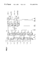
- FIG. 1 shows the circuit structure of a physical layer 3 according to an embodiment of the invention
- FIG. 6 is a timing chart illustrating the an operation of the physical layer 3 .
- the physical layer 3 is the same as that used in the node ND shown in FIG. 3 .
- the physical layer 3 transmits signals Data, ⁇ Data, Strobe, and ⁇ Strobe over the cable BS.
- the physical layer 3 parallel-serial converts input 8-bit parallel data T ⁇ D[ 0 ] to T ⁇ D[ 7 ] and outputs pairs of differential serial data signals Data and ⁇ Data, as well as pairs of differential strobe signals Strobe and ⁇ Strobe.
- the strobe signals Strobe and ⁇ Strobe are signals obtained by DS encoding the data signals Data and ⁇ Data, and are transmitted in place of clocks signals (e.g., 400 MHz).
- a partner physical layer receives the data signals Data and ⁇ Data and strobe signals Strobe and ⁇ Strobe, and reproduces clock signals by decoding the data and strobe signals.
- the physical layer 3 parallel-serial converts the signals Data, ⁇ Data, Strobe, and ⁇ Strobe by using clocks Clk 1 and Clk 2 of a relatively low frequency 200 MHz instead of using clocks of a high frequency 400 MHz, and transmits the converted signals over the cable BS at 400 MHz.
- a main difference of the physical layer 3 from the conventional physical layer 3 is that the embodiment physical layer 3 has double-edge trigger flip-flops DFF 0 to DFF 7 and differential multiplexers MUX 1 and MUX 2 .
- the double edge trigger flip-flops DFF 0 to DFF 7 use both the positive (rise) and negative (fall) edges as their triggers.
- the differential multiplexers MUX 1 and MUX 2 are novel devices proposed by the present inventor. The details thereof will be given later.
- Eight selectors SEL 0 to Sel 7 and eight double-edge trigger flip-flops DFF 0 to DFF 7 are respectively (alternately) and serially connected to constitute a parallel-serial converter circuit. Similar to that shown in FIG. 4, this parallel-serial converter circuit converts 8-bit parallel data T ⁇ D[ 0 ] to T ⁇ D[ 7 ] into serial data N 1 . In the following, only the different points of the physical layer 3 shown in FIGS. 1 and 6 from that shown in FIGS. 4 and 5 will be described.
- the double-edge trigger flip-flops DFF 0 to DFF 7 are used.
- the double-edge trigger flip-flops DFF 0 to DFF 7 hold and output input signals D as output signals Q, by using double edges (positive and negative edges) of the clock Clk 1 as triggers.
- the clocks Clk 1 and Clk 2 shown in FIG. 4 have a frequency of 400 MHz (2.5 ns period).
- the clocks Clk 1 and Clk 2 have a frequency of 200 MHz (5 ns period).
- the operation same as the physical layer shown in FIG. 4 can be executed with low frequency clocks of 200 MHz instead of high frequency clocks of 400 MHz.
- the double-edge trigger flip-flops DFF 0 to DFF 7 output serial data N 1 by using the double edges of the clock Clk 1 having a frequency of 200 MHz as triggers.
- serial data N 1 data D 0 to D 7 is sequentially output and then data D 8 to D 15 is sequentially output.
- serial data N 1 of 200 Mbps is obtained.
- serial data N 1 of 400 Mbps can be obtained.
- An XOR circuit 10 performs a logical sum of the serial data N 1 and a clock signal enc to output a strobe signal N 1 of 400 Mbps.
- the strobe signal N 2 includes data S 0 , S 1 , S 2 , S 3 , S 4 , S 5 , . . . , sequentially in this order which is delayed from the serial data N 1 by a process time of the XOR circuit 10 .
- the strobe signals N 1 and N 2 having a frequency of 400 MHz cannot be transmitted directly to another node. The reason for this will be described by taking the strobe signal N 1 as an example.
- FIG. 7A is a filing chart shown in a large scale of the clock signal Clk 1 and serial strobe signal N 2 shown in FIG. 6 .
- the clock Clk 1 is generated by a known phase locked loop (PLL) circuit.
- PLL phase locked loop
- a time period T 1 is a time from a positive edge of the clock Clk 1 to the next positive edge.
- a time period T 2 is a time from a negative edge of the clock Clk 1 to the next negative edge. The time periods T 1 and T 2 are nearly equal.
- a time period T 3 is a time from a positive edge of the clock Clk 1 to the next negative edge.
- a time period T 4 is a time from a negative edge of the clock Clk 1 to the next positive edge.
- the time periods T 3 and T 4 are usually different because of a difference between rise and fall characteristics of the clock Clk 1 .
- CMOS transistors of the PLL circuit are characteristics of CMOS transistors of the PLL circuit.
- the positive edge of the clock Clk 1 depends on the on-characteristics of an n-channel MOS transistor, and the negative edge of the clock Clk 1 depends on the on-characteristics of a p-channel MOS transistor. It is difficult to have the same on-characteristics of both the n- and p-channel MOS transistors, and in addition, because of a temperature change and process variation, the time periods T 3 and T 4 are usually different.
- the duty ratio of the clock Clk 1 is 50%. However, it is difficult to set this duty ratio to 50% because there is often a time shift between the positive and negative edges. This time shift is a so-called jitter.
- the serial data N 1 has ajitter. If the duty ratio of the clock Clk 1 is 50%, the jitter of the data N 1 is not present. However, from the above reason, the duty ratio of the clock Clk 1 is difficult to be set to 50%, and therefore the data N 1 has a jitter.
- the IEEE 1394 specification stipulates that the jitter contained in an output signal should be 0.15 ns or shorter when the output signals Data, ⁇ Data, Strobe, and ⁇ Strobe have the signal rate of 400 Mbps. Since the jitter of the data N 1 becomes longer than 0.15 ns, the IEEE 1394 specification cannot be satisfied.
- the output signals Data, ⁇ Data, Strobe, and ⁇ Strobe are reproduced from the data N 1 in the manner similar to the physical layer shown in FIG. 4, a skew among the four output signals becomes large.
- the skew is an average (collective) time shift between synchronized signals.
- the IEEE 1394 specification stipulates that the skew among the output signals Data, ⁇ Data, Strobe, ⁇ Strobe should be 0.1 ns or shorter when the output signals have the signal rate of 400 Mbps. Since the skew among the output signals reproduced in the above manner becomes longer than 0.1 ns, the IEEE 1394 specification cannot be satisfied.
- the signal N 1 is input to input terminals D of single edge trigger D-type flip-flops SFF 1 and SFF 1
- a signal N 2 which is an output from the XOR circuit 10 is input to input terminals D of single edge trigger D-type flip-flops SFF 3 and SFF 4 .
- the flip-flow SFF 1 outputs the input signal N 1 (at terminal D) as an output signal Deven (at terminal Q) by using the negative edge of the clock Clk 1 having a frequency of 200 MHz.
- the input signal N 1 of 400 Mbps is therefore converted into the output signal Deven of 200 Mbps.
- the output signal Deven includes even number data D 0 , D 2 , D 4 , . . . among the input signal N 1 .
- the flip-flow SFF 2 outputs the input signal N 1 (at terminal D) as an output signal Dodd (at terminal Q) by using the positive edge of the clock Clk 1 having a frequency of 200 MHz.
- the output signal Dodd has a signal rate of 200 Mbps and includes odd number data D 1 , D 3 , D 5 , . . . among the input signal N 1 .
- the flip-flops SFF 1 and SFF 2 therefore convert the serial data N 1 of 400 Mbps into two-bit parallel data Deven and Dodd of 200 Mbps.
- the flip-flop SFF 3 outputs the input signal N 2 (at terminal D) as an output signal Seven (at terminal Q) by using the negative edge of the clock Clk 2 having a frequency of 200 MHz.
- the output signal Seven has a signal rate of 200 Mbps and includes even number data S 0 , S 2 , S 4 , . . . among the input signal N 2 .
- the flip-flop SFF 4 outputs the input signal N 2 (at terminal D) as an output signal Sodd (at terminal Q) by using the positive edge of the clock Clk 2 having a frequency of 200 MHz.
- the output signal Sodd has a signal rate of 200 Mbps and includes odd number data S 1 , S 3 , S 5 , . . . among the input signal N 2 .
- the flip-flops SFF 3 and SFF 4 therefore convert the serial data N 2 of 400 Mbps into two-bit parallel data Seven and Sodd of 200 Mbps.
- the differential multiplexer MUX 1 has a positive input terminal p and a negative input terminal n.
- the signal Deven is applied to the input terminal p, and the signal Dodd is applied to the input terminal n.
- the differential multiplexer MUX 1 uses a pair of differential clocks Clkp and Clkn as select signals.
- the differential clocks Clkp and Clkn have a frequency of 200 MHz and opposite phases.
- the differential multiplexer MUX 1 outputs the signal Deven at the input terminal p as a pair of differential data signals Data and ⁇ Data, if the select signal Clkp is larger than the select signal Clkn.
- the differential multiplexer MUX 1 outputs the signal Dodd at the input terminal n as a pair of differential data signals Data and ⁇ Data.
- the differential clocks Clkp and Clkn have a frequency of 200 MHz.
- a pair of differential signals Data and ⁇ Data have opposite phases and a signal rate of 400 Mbps.
- the differential multiplexer MUX 2 receives the signal Seven at its positive input terminal p and the signal Sodd at its negative input terminal n, and uses a pair of differential clocks Clkp and Clkn as its select signals.
- the differential multiplexer MUX 2 outputs the signal Seven at the input terminal p as a pair of differential signals Strobe and ⁇ Strobe, if the select signal Clkp is larger than the select signal Clkn.
- the differential multiplexer MUX 2 outputs the signal Dodd at the input terminal n as a pair of differential signals Strobe and ⁇ Strobe.
- the differential clocks Clkp and Clkn have a frequency of 200 MHz.
- a pair of differential signals Strobe and ⁇ Strobe have opposite phases and a signal rate of 400 Mbps.
- the differential multiplexers MUX 1 and MUX 2 synchronize the four output signals Data, ⁇ Data, Strobe, and ⁇ Strobe by using the differential clocks Clkp and Clkn as the select signals.
- the differential multiplexers MUX 1 and MUX 2 use the differential clocks Clkp and Clkn as the select signals, a jitter of the output signal can be made almost zero. The reason for this will be described by using the output signal Data of the differential multiplexer MUX 1 as an example.
- FIG. 7B is a timing chart shown in a large scale of a pair of differential clocks Clkp and Clkn of shown in FIG. 6 .
- a time period T 5 is a time from a first cross point between the differential clocks Clkp and Clkn to the next cross point.
- a time period T 6 is a time from a second cross point between the differential clocks Clkp and Clkn to the next third cross point. The time periods T 5 and T 6 are nearly equal.
- the differential multiplexer MUX 1 switches the output signal at the cross point between the differential clocks Clkp and Clkn. Therefore, of the output signal Data, the time period T 5 of the data D 0 becomes equal to the time period T 6 of the data D 1 . The jitter of the output signal Data therefore becomes nearly zero. Similarly, the skew of the four output signals becomes nearly zero.
- the physical layer 3 does not require clocks of 400 MHz, and it is sufficient if clocks of 200 MHz are provided.
- the physical layer 3 of this embodiment operates at low frequency clocks of 200 MHz. Therefore, as compared to the conventional physical layer (FIG. 4) operating at high frequency clocks of 400 MHz, it is not necessary to use sophisticated semiconductor process technologies which are required to realize high speed operation and high precision alignment, so that the manufacture cost can be lowered. Furthermore, since the clock frequency is lowered, the stable operation is ensured while the power consumption is reduced so that market needs can be satisfied.
- FIG. 8 shows the structure of a signal generator for generating signals to be supplied to the physical layer 3 shown in FIG. 1 .
- the phase locked loop (PLL) circuit 21 is a known general circuit and has a voltage controlled oscillator (VCO) 22 .
- VCO 11 has an odd number (e.g., three) of differential delay blocks 23 a , 23 b , and 23 c . In the following, all or each of the differential delay blocks 23 a , 23 b , and 23 c is simply called a differential delay block 23 , where applicable.
- the three differential delay blocks 23 are serially connected. An output signal of the last stage third differential delay block 23 c is fed back to an input terminal of the first differential delay block 23 a.
- An output signal of each differential delay block 23 is inverted and supplied to the next stage differential delay block 23 .
- a non-inverted output signal of the first differential delay block 23 a is input to an inverting input terminal of the second differential delay block 23 b
- the inverted output signal of the first differential delay block 23 a is input to a non-inverting input terminal of the second differential delay block 23 b.
- VCO 22 outputs a pair of differential clocks Clkp and Clkn having a frequency of 200 MHz.
- the differential clocks Clkp and Clkn have opposite phases (a phase difference of 180°), and are supplied to the differential multiplexers MUX 1 and MUX 2 shown in FIG. 1 .
- PLL 21 has an output stage 24 in addition to VCO 22 .
- the output stage 24 receives the differential clocks Clkp and Clkn of 200 MHz and output clocks Clk 1 and Clk 2 of 200 MHz.
- the clocks Clk 1 and Clk 2 may be the same signal or different signals so long as they have the same frequency of 200 MHz. In this embodiment, the same signal is used for the clock signals Clk 1 and Clk 2 .
- the clock Clk 1 is supplied to the double-edge trigger flip-flops DFF 0 to DFF 7 shown in FIG. 1, and the clock Clk 2 is supplied to the single edge trigger flip-flops SFF 1 to SFF 4 shown in FIG. 1 .
- a clock generator circuit 25 generates a signal enc of 200 MHz and a signal Mux_Sel of 50 MHz from the clocks Clk 1 and Clk 2 of 200 MHz.
- the signal enc is supplied to the XOR circuit 10 shown in FIG. 1 and the signal Mux_Sel is supplied to the selectors SEL 0 to SEL 7 .
- FIG. 9 is a circuit diagram of each of the double-edge trigger D-type flip-flops DFF 0 to DFF 7 shown in FIG. 1 .
- the flip-flops DFF 0 to DFF 7 are made of CMOS circuits. An input signal is applied to an input terminal D, and a clock signal Clk 1 is applied to a clock terminal Clk.
- a clock signal Clk 1 is applied to a clock terminal Clk.
- FIG. 9 although an inverted output terminal ⁇ Q is shown, the output terminal Q shown in FIG. 1 can be provided by inverting a signal at the output terminal ⁇ Q.
- a terminal vdd is a positive potential terminal of a power source
- a terminal gnd is a ground potential terminal.
- Each of the flip-flops DFF 0 to DFF 7 has an upper circuit portion 11 and a lower circuit portion 12 .
- the upper circuit portion 11 is a flip-flop which is triggered by the negative edge of the clock Clk 1
- the lower circuit portion 11 is a flip-flop which is triggered by the positive edge of the clock Clk 1 .
- An output of the upper circuit portion 11 takes a high impedance state when the clock Clk 1 takes a high level
- an output of the lower circuit portion 12 takes a high impedance state when the clock Clk 1 takes a low level. Therefore, there is no conflict between the outputs of the upper and lower circuit portions 11 and 12 , and the output signals can be derived from the output terminal ⁇ Q by using the double edges of the clock Clk 1 as triggers.
- a circuit may be used which is described in the document “IEEE Journal of Solid-state Circuits, vol. 26, No. 8, August, 1991” at pp. 1168 to 1170.
- FIG. 10 is a circuit diagram of each of the differential multiplexers MUX 1 and MUX 2 shown in FIG. 1 .
- the differential multiplexers MUX 1 and MUX 2 are made of CMOS circuits. In the following, the MOS transistor is called simply a transistor.
- a terminal vdd is a positive potential terminal of a power source
- a terminal gnd is a ground potential terminal.
- the differential multiplexer has four nodes Vinp, ⁇ Vinp, Vinn, and ⁇ Vinn.
- even number data Deven (FIG. 1) is input to the positive input node Vinp, and even number data Deven inverted by an inverter (NOT) circuit 31 is input to the positive inverting input node ⁇ Vinp.
- odd number data Dodd (FIG. 1) is input to the negative input node Vinn, and odd number data Dodd inverted by an inverter (NOT) circuit 32 is input to the negative inverting input node ⁇ Vinn.
- the differential multiplexer has differential clock nodes Clkp and Clkn and differential output nodes Voutp and Voutn. From the positive output node Voutp, the output signal Data or Strobe shown in FIG. 1 is output. From the negative output node Voutn, the output signal ⁇ Data or ⁇ Strobe shown in FIG. 1 is output.
- the signal at the positive input node Vinp is output from the positive output node Voutp, and the paired differential signal of the signal output from the positive output node Voutp is output from the negative output node Voutn.
- the positive clock Clkn is smaller than the negative clock Clkn, the signal at the negative input node Vinn is output from the positive output node Voutp, and the paired differential signal of the signal output from the positive output node Voutp is output from the negative output node Voutn.
- the positive input node Vinp is connected to the gate of an n-channel transistor M 1 .
- the positive inverting input node ⁇ Vinp is connected to the gate of an n-channel transistor M 2 .
- the negative input node Vinn is connected to the gate of an n-channel transistor M 3 .
- the negative inverting input node ⁇ Vinn is connected to the gate of an n-channel transistor M 4 .
- the drains of the transistors M 1 and M 3 are connected to the drain of a p-channel transistor M 7 and a negative node Nn.
- the drains of the transistors M 2 and M 4 are connected to the drain of a p-channel transistor M 8 and a positive node Np.
- a constant current source 12 is connected at its one end to the ground terminal and at its other end to the drain of a p-channel transistor M 9 .
- the sources of the transistors M 7 , M 8 , and M 9 are connected to the positive potential terminal vdd.
- the gate of the transistors M 7 , M 8 , and M 9 are connected in common.
- the drain and gate of the transistor M 9 are connected in common.
- the transistors M 7 and M 8 together with the transistor M 9 constitute a current mirror circuit.
- the transistors M 7 and M 8 can flow a current having the same amount as the current of the transistor M 9 .
- the transistors M 7 and M 8 may be replaced by a constant current source.
- the positive clock node Clkp is connected to the gate of an n-channel transistor M 5 .
- the negative clock node Clkn is connected to the gate of an n-channel transistor M 6 .
- the drain of the transistor M 5 is connected to the sources of the transistors M 1 and M 2 , and the source thereof is connected to the ground terminal gnd.
- the drain of a transistor M 6 is connected to the sources of the transistors M 3 and M 4 , and the source thereof is connected to the ground terminal gnd.
- the positive clock Clkp takes the high level (hereinafter represented by “H”) and the negative clock Clkn takes the low level (hereinafter represented by “L”).
- H the positive clock Clkp takes the high level
- L the negative clock Clkn takes the low level
- the transistor M 6 turns off so that the current will not flow through the transistors M 3 and M 4 irrespective of the logical values of the negative inputs Vinn and ⁇ Vinn.
- positive node Np and negative node Nn can be used as the output terminals. Namely, from the positive node Np, the signals Data and Strobe shown in FIG. 1 are output, and from the negative node Nn, the signals ⁇ Data and ⁇ Strobe shown in FIG. 1 are output.
- the above circuit structure can be used as the differential multiplexer.
- the output stages described in the following are required to be connected to the above-described circuit in order to realize current amplification.
- Transistors M 11 , M 12 , M 13 , M 14 , and M 15 constitute an output stage for the positive output node Voutp.
- Transistors M 16 , M 17 , M 18 , M 19 , and M 20 constitute an output stage of the negative output node Voutn.
- a constant current source 11 is connected to the drain of a p-channel transistor M 10 .
- the p-channel transistors M 11 and M 16 together with the transistor M 10 constitute a current mirror circuit.
- the sources of the transistors M 10 , M 11 , and M 16 are connected to the positive potential terminal vdd.
- the transistors M 11 and M 16 can flow a current having the same amount of the current of the transistor M 10 .
- the transistors M 11 and M 16 may be replaced by a constant current source.
- the positive node Np is connected to the gates of the transistors M 12 and M 18
- the negative node Nn is connected to the gates of the transistors M 13 and M 17 . Similar to the above-described circuit operation, the operation when the potential at the positive node Np rises and the potential at the negative node Nn lowers, will be described.
- the p-channel transistor M 12 turns off so that current flowing through the source-drain reduces.
- the p-channel transistor M 13 turns on so that current flowing through the source-drain increases.
- the n-channel transistors M 14 and M 15 constitute a current mirror circuit.
- the p-channel transistor M 17 turns on so that the current flowing through the source-drain increases.
- the p-channel transistor M 18 turns off so that the current flowing through the source-drain reduces.
- a paired differential signal of the signal output from the positive output node Voutp (output node of the signal ⁇ Data or ⁇ Strobe shown in FIG. 1) is output from the negative output node Voutn (output node of the signal Data or Strobe shown in FIG. 1 ).
- the transistor M 1 turns off and the transistor M 2 turns on.
- the gate potential at the transistors M 12 and M 18 lowers, whereas as the potential at the negative node Nn rises, the gate potential of the transistors M 13 and M 17 rises.
- the transistor M 13 turns off and the current flowing through the source-drain reduces, and the transistor M 12 turns on and the current flowing through the source-drain increases.
- the signal input to the positive input node Vinp is selected and output from the output node Voutp.
- the transistor M 6 turns on, and the differential amplifier constituted of the transistors M 3 and M 4 becomes active.
- the transistor M 5 turns off, and the differential amplifier constituted of the transistors M 1 and M 2 enters a cut-off state.
- the signal of the negative input node Vinn is multiplexed to be output from the positive output node Voutp.
- the paired differential signal of the signal output from the positive output node Voutp is output from the negative output node Voutn.
- the circuit of the differential multiplexer is in perfect symmetry with reference to the differential clocks Clkp and Clkn. Therefore, a change from the state of Clfp>Clkn to the state of Clkp ⁇ Clkn is principally the same as a change from the state of Clkp ⁇ Clkn to the state of Clkp>Clkn.
- the obtained differential outputs Voutp and Voutn can realize the low jitter and skew characteristics satisfying the IEEE 1394 specification.
- the transistors are not limited only to MOS transistors, but other transistors such ad junction type field effect transistors and bipolar transistors may also be used.
- the physical layer (FIG. 1) of this embodiment can perform parallel-serial conversion by using low frequency (200 MHz) clocks and output the signals Data, ⁇ Data, Strobe, and ⁇ Strobe at a high signal rate (400 Mbps). Furthermore, the jitter and skew of the output signal can be reduced to such an extent that the IEEE 1394 specification can be satisfied.
- the physical layer can be operated with low frequency clocks, it is not necessary to use sophisticated semiconductor process technologies which are required to realize high speed operation and high precision alignment, so that the manufacture cost can be lowered. Furthermore, since the clock frequency is lowered, the stable operation is ensured while the power consumption is reduced so that market needs can be satisfied.
- the clock frequency and output signal rate are not limited only to those described above.
- output signals having a signal rate of 200 Mbps may be transmitted by using 100 MHz clocks.
- the physical layer and differential multiplexer of this embodiment are not limited only to IEEE 1394 serial communications. For example, they may be applied to communications using a universal serial bus (USB) interface.
- USB universal serial bus
Abstract
Description
Claims (21)
Applications Claiming Priority (4)
| Application Number | Priority Date | Filing Date | Title |
|---|---|---|---|
| JP10-11741 | 1998-01-23 | ||
| JP1173998A JP3739024B2 (en) | 1998-01-23 | 1998-01-23 | Differential logic circuit for parallel-serial conversion |
| JP10-11739 | 1998-01-23 | ||
| JP1174198A JPH11214975A (en) | 1998-01-23 | 1998-01-23 | Differential multiplexer |
Publications (1)
| Publication Number | Publication Date |
|---|---|
| US6188339B1 true US6188339B1 (en) | 2001-02-13 |
Family
ID=26347247
Family Applications (1)
| Application Number | Title | Priority Date | Filing Date |
|---|---|---|---|
| US09/229,673 Expired - Fee Related US6188339B1 (en) | 1998-01-23 | 1999-01-13 | Differential multiplexer and differential logic circuit |
Country Status (1)
| Country | Link |
|---|---|
| US (1) | US6188339B1 (en) |
Cited By (45)
| Publication number | Priority date | Publication date | Assignee | Title |
|---|---|---|---|---|
| US20020130692A1 (en) * | 1999-06-28 | 2002-09-19 | Broadcom Corporation | Current-controlled CMOS logic family |
| US20020171095A1 (en) * | 2001-05-17 | 2002-11-21 | Afshin Momtaz | Layout technique for C3MOS inductive broadbanding |
| US20020190770A1 (en) * | 1999-06-28 | 2002-12-19 | Broadcom Corporation | Current -controlled CMOS circuit using higher voltage supply in low voltage CMOS process |
| US20030007162A1 (en) * | 2001-06-29 | 2003-01-09 | Marc Blumer | Digital pulse width modulator for use in electrostatic printing mechanisms |
| US6535032B2 (en) * | 2001-04-25 | 2003-03-18 | Micron Technology, Inc. | Data receiver technology |
| US20030067337A1 (en) * | 1999-06-28 | 2003-04-10 | Broadcom Corporation | Current-controlled CMOS circuit using higher voltage supply in low voltage CMOS process |
| EP1304802A1 (en) * | 2001-10-19 | 2003-04-23 | Fujitsu Limited | Multiplexer circuit for converting parallel data into serial data at high speed and synchronized with a clock signal |
| US20030122603A1 (en) * | 2000-02-24 | 2003-07-03 | Broadcom Corporation | Current-controlled CMOS circuits with inductive broadbanding |
| US6614291B1 (en) * | 2001-06-15 | 2003-09-02 | Lattice Semiconductor Corp. | Low voltage, high speed CMOS CML latch and MUX devices |
| US6642861B1 (en) * | 2002-04-26 | 2003-11-04 | Intel Corporation | Arrangements having ternary-weighted parameter stepping |
| US20040133912A1 (en) * | 2002-10-22 | 2004-07-08 | Chris Thomas | Method and apparatus of IEEE 1394 tone transmission in beta mode |
| US20040170176A1 (en) * | 1999-03-17 | 2004-09-02 | Broadcom Corporation | Method for handling IP multicast packets in network switch |
| US20050012400A1 (en) * | 2003-07-16 | 2005-01-20 | M/A Com, Inc. | Radiofrequency double pole single throw switch |
| US6859454B1 (en) * | 1999-06-30 | 2005-02-22 | Broadcom Corporation | Network switch with high-speed serializing/deserializing hazard-free double data rate switching |
| US20050062864A1 (en) * | 2003-09-04 | 2005-03-24 | Keiji Mabuchi | Solid-state image sensing apparatus |
| US20050141501A1 (en) * | 1999-03-17 | 2005-06-30 | Broadcom Corporation | Network switch having a programmable counter |
| US6943597B1 (en) * | 2002-11-19 | 2005-09-13 | Xilinx, Inc. | Hard phase alignment of clock signals with an oscillator controller |
| US20050248383A1 (en) * | 2004-05-06 | 2005-11-10 | Wayne Fang | Pulse multiplexed output system |
| US20060044010A1 (en) * | 2004-08-31 | 2006-03-02 | Intel Corporation | Symmetric and non-stacked XOR circuit |
| US20070025435A1 (en) * | 2005-07-29 | 2007-02-01 | Jun Cao | Current-controlled CMOS (C3MOS) fully differential integrated wideband amplifier/equalizer with adjustable gain and frequency response without additional power or loading |
| US20070024369A1 (en) * | 2005-07-29 | 2007-02-01 | Jun Cao | Current-controlled CMOS (C3MOS) wideband input data amplifier for reduced differential and common-mode reflection |
| US20070052467A1 (en) * | 2005-09-06 | 2007-03-08 | Jun Cao | Current-controlled CMOS (C3MOS) fully differential integrated delay cell with variable delay and high bandwidth |
| US20070103218A1 (en) * | 2003-03-13 | 2007-05-10 | Fujitsu Limited | Logical circuit |
| US20070194956A1 (en) * | 2006-02-20 | 2007-08-23 | Samsung Electronics Co., Ltd. | Serializer and method of converting parallel data into serial data |
| US20070296401A1 (en) * | 2006-06-07 | 2007-12-27 | Reimund James A | Interleaved Differential Multiplexer |
| US20080303761A1 (en) * | 2007-06-07 | 2008-12-11 | Sanyo Electric Co., Ltd. | Data Output Circuit |
| US20090309771A1 (en) * | 2007-02-26 | 2009-12-17 | Fujitsu Limited | Data transmission circuit and data communication system |
| US7849208B2 (en) | 2002-08-30 | 2010-12-07 | Broadcom Corporation | System and method for TCP offload |
| US7912064B2 (en) | 2002-08-30 | 2011-03-22 | Broadcom Corporation | System and method for handling out-of-order frames |
| US7934021B2 (en) | 2002-08-29 | 2011-04-26 | Broadcom Corporation | System and method for network interfacing |
| US7990296B1 (en) * | 2010-03-10 | 2011-08-02 | Smsc Holdings S.A.R.L. | High speed low power cell providing serial differential signals |
| US8116203B2 (en) | 2001-07-23 | 2012-02-14 | Broadcom Corporation | Multiple virtual channels for use in network devices |
| US8135016B2 (en) | 2002-03-08 | 2012-03-13 | Broadcom Corporation | System and method for identifying upper layer protocol message boundaries |
| RU2449469C1 (en) * | 2011-05-23 | 2012-04-27 | Государственное образовательное учреждение высшего профессионального образования "Пермский государственный технический университет" | Functionally complete tolerant element |
| US8180928B2 (en) | 2002-08-30 | 2012-05-15 | Broadcom Corporation | Method and system for supporting read operations with CRC for iSCSI and iSCSI chimney |
| EP2515443A1 (en) * | 2011-04-21 | 2012-10-24 | STMicroelectronics SA | Data serializer |
| US8402142B2 (en) | 2002-08-30 | 2013-03-19 | Broadcom Corporation | System and method for TCP/IP offload independent of bandwidth delay product |
| US20130161492A1 (en) * | 2011-12-26 | 2013-06-27 | Korea Advanced Institute Of Science And Technology | Switching circuit, charge sense amplifier including switching circuit, and photon counting device including switching circuit |
| US8493248B2 (en) * | 2011-05-03 | 2013-07-23 | Ipgoal Microelectronics (Sichuan) Co., Ltd. | Transforming circuit and system between parallel data and serial data |
| US20130341733A1 (en) * | 2012-06-25 | 2013-12-26 | International Business Machines Corporation | Plural Differential Pair Employing FinFET Structure |
| US8706917B1 (en) * | 2001-05-02 | 2014-04-22 | Nvidia Corporation | General purpose input/output controller |
| US8750320B2 (en) | 1997-01-23 | 2014-06-10 | Broadcom Corporation | Fibre channel arbitrated loop bufferless switch circuitry to increase bandwidth without significant increase in cost |
| US8798091B2 (en) | 1998-11-19 | 2014-08-05 | Broadcom Corporation | Fibre channel arbitrated loop bufferless switch circuitry to increase bandwidth without significant increase in cost |
| US9024387B2 (en) | 2012-06-25 | 2015-05-05 | International Business Machines Corporation | FinFET with body contact |
| US9350335B1 (en) * | 2015-09-24 | 2016-05-24 | Inphi Corporation | Single stage latency combined multiplexer and latch circuit |
Citations (1)
| Publication number | Priority date | Publication date | Assignee | Title |
|---|---|---|---|---|
| US6008670A (en) * | 1997-08-19 | 1999-12-28 | Hewlett-Packard | Differential CMOS logic family |
-
1999
- 1999-01-13 US US09/229,673 patent/US6188339B1/en not_active Expired - Fee Related
Patent Citations (1)
| Publication number | Priority date | Publication date | Assignee | Title |
|---|---|---|---|---|
| US6008670A (en) * | 1997-08-19 | 1999-12-28 | Hewlett-Packard | Differential CMOS logic family |
Cited By (88)
| Publication number | Priority date | Publication date | Assignee | Title |
|---|---|---|---|---|
| US8774199B2 (en) | 1997-01-23 | 2014-07-08 | Broadcom Corporation | Fibre channel arbitrated loop bufferless switch circuitry to increase bandwidth without significant increase in cost |
| US8750320B2 (en) | 1997-01-23 | 2014-06-10 | Broadcom Corporation | Fibre channel arbitrated loop bufferless switch circuitry to increase bandwidth without significant increase in cost |
| US8767756B2 (en) | 1997-01-23 | 2014-07-01 | Broadcom Corporation | Fibre channel arbitrated loop bufferless switch circuitry to increase bandwidth without significant increase in cost |
| US8798091B2 (en) | 1998-11-19 | 2014-08-05 | Broadcom Corporation | Fibre channel arbitrated loop bufferless switch circuitry to increase bandwidth without significant increase in cost |
| US20040170176A1 (en) * | 1999-03-17 | 2004-09-02 | Broadcom Corporation | Method for handling IP multicast packets in network switch |
| US7782891B2 (en) | 1999-03-17 | 2010-08-24 | Broadcom Corporation | Network switch memory interface configuration |
| US7720055B2 (en) | 1999-03-17 | 2010-05-18 | Broadcom Corporation | Method for handling IP multicast packets in network switch |
| US20080056278A1 (en) * | 1999-03-17 | 2008-03-06 | Broadcom Corporation | Network switch memory interface configuration |
| US7643481B2 (en) | 1999-03-17 | 2010-01-05 | Broadcom Corporation | Network switch having a programmable counter |
| US20050141501A1 (en) * | 1999-03-17 | 2005-06-30 | Broadcom Corporation | Network switch having a programmable counter |
| US20030067337A1 (en) * | 1999-06-28 | 2003-04-10 | Broadcom Corporation | Current-controlled CMOS circuit using higher voltage supply in low voltage CMOS process |
| US8823435B2 (en) | 1999-06-28 | 2014-09-02 | Broadcom Corporation | Current-controlled CMOS logic family |
| US8299834B2 (en) | 1999-06-28 | 2012-10-30 | Broadcom Corporation | Current-controlled CMOS logic family |
| US10396763B2 (en) | 1999-06-28 | 2019-08-27 | Avago Technologies International Sales Pte. Limited | Current-controlled CMOS logic family |
| US20020190770A1 (en) * | 1999-06-28 | 2002-12-19 | Broadcom Corporation | Current -controlled CMOS circuit using higher voltage supply in low voltage CMOS process |
| US20040227544A1 (en) * | 1999-06-28 | 2004-11-18 | Guangming Yin | Current-controlled CMOS circuit using higher voltage supply in low voltage CMOS process |
| US9831853B2 (en) | 1999-06-28 | 2017-11-28 | Avago Technologies General Ip (Singapore) Pte. Ltd. | Current-controlled CMOS logic family |
| US20030001646A1 (en) * | 1999-06-28 | 2003-01-02 | Broadcom Corporation | Current-controlled CMOS logic family |
| US9112487B2 (en) | 1999-06-28 | 2015-08-18 | Broadcom Corporation | Current-controlled CMOS logic family |
| US7724057B2 (en) | 1999-06-28 | 2010-05-25 | Broadcom Corporation | Current-controlled CMOS logic family |
| US20020130692A1 (en) * | 1999-06-28 | 2002-09-19 | Broadcom Corporation | Current-controlled CMOS logic family |
| US6859454B1 (en) * | 1999-06-30 | 2005-02-22 | Broadcom Corporation | Network switch with high-speed serializing/deserializing hazard-free double data rate switching |
| US7919985B2 (en) | 2000-02-24 | 2011-04-05 | Broadcom Corporation | Current-controlled CMOS circuits with inductive broadbanding |
| US20030122603A1 (en) * | 2000-02-24 | 2003-07-03 | Broadcom Corporation | Current-controlled CMOS circuits with inductive broadbanding |
| US6535032B2 (en) * | 2001-04-25 | 2003-03-18 | Micron Technology, Inc. | Data receiver technology |
| US8706917B1 (en) * | 2001-05-02 | 2014-04-22 | Nvidia Corporation | General purpose input/output controller |
| US20020171095A1 (en) * | 2001-05-17 | 2002-11-21 | Afshin Momtaz | Layout technique for C3MOS inductive broadbanding |
| US6614291B1 (en) * | 2001-06-15 | 2003-09-02 | Lattice Semiconductor Corp. | Low voltage, high speed CMOS CML latch and MUX devices |
| US6992792B2 (en) | 2001-06-29 | 2006-01-31 | Electronics For Imaging, Inc. | Digital pulse width modulator for use in electrostatic printing mechanisms |
| US7453596B2 (en) | 2001-06-29 | 2008-11-18 | Electronics For Imaging, Inc. | Digital pulse width modulator for use in electrostatic printing mechanisms |
| US20060087693A1 (en) * | 2001-06-29 | 2006-04-27 | Electronics For Imaging, Inc. | Digital pulse width modulator for use in electrostatic printing mechanisms |
| US20030007162A1 (en) * | 2001-06-29 | 2003-01-09 | Marc Blumer | Digital pulse width modulator for use in electrostatic printing mechanisms |
| WO2003003713A1 (en) * | 2001-06-29 | 2003-01-09 | Electronics For Imaging, Inc. | Digital pulse width modulator for use in electrostatic printing mechanisms |
| US8493857B2 (en) | 2001-07-23 | 2013-07-23 | Broadcom Corporation | Multiple logical channels for use in network devices |
| US8116203B2 (en) | 2001-07-23 | 2012-02-14 | Broadcom Corporation | Multiple virtual channels for use in network devices |
| US9036643B2 (en) | 2001-07-23 | 2015-05-19 | Broadcom Corporation | Multiple logical channels for use in network devices |
| US20030076821A1 (en) * | 2001-10-19 | 2003-04-24 | Fujitsu Limited | Multiplexer circuit for converting parallel data into serial data at high speed and synchronized with a clock signal |
| US7154918B2 (en) | 2001-10-19 | 2006-12-26 | Fujitsu Limited | Multiplexer circuit for converting parallel data into serial data at high speed and synchronized with a clock signal |
| EP1304802A1 (en) * | 2001-10-19 | 2003-04-23 | Fujitsu Limited | Multiplexer circuit for converting parallel data into serial data at high speed and synchronized with a clock signal |
| US8135016B2 (en) | 2002-03-08 | 2012-03-13 | Broadcom Corporation | System and method for identifying upper layer protocol message boundaries |
| US8345689B2 (en) | 2002-03-08 | 2013-01-01 | Broadcom Corporation | System and method for identifying upper layer protocol message boundaries |
| US8451863B2 (en) | 2002-03-08 | 2013-05-28 | Broadcom Corporation | System and method for identifying upper layer protocol message boundaries |
| US8958440B2 (en) | 2002-03-08 | 2015-02-17 | Broadcom Corporation | System and method for identifying upper layer protocol message boundaries |
| US6642861B1 (en) * | 2002-04-26 | 2003-11-04 | Intel Corporation | Arrangements having ternary-weighted parameter stepping |
| US7934021B2 (en) | 2002-08-29 | 2011-04-26 | Broadcom Corporation | System and method for network interfacing |
| US8549152B2 (en) | 2002-08-30 | 2013-10-01 | Broadcom Corporation | System and method for TCP/IP offload independent of bandwidth delay product |
| US7912064B2 (en) | 2002-08-30 | 2011-03-22 | Broadcom Corporation | System and method for handling out-of-order frames |
| US7929540B2 (en) | 2002-08-30 | 2011-04-19 | Broadcom Corporation | System and method for handling out-of-order frames |
| US8677010B2 (en) | 2002-08-30 | 2014-03-18 | Broadcom Corporation | System and method for TCP offload |
| US7849208B2 (en) | 2002-08-30 | 2010-12-07 | Broadcom Corporation | System and method for TCP offload |
| US8402142B2 (en) | 2002-08-30 | 2013-03-19 | Broadcom Corporation | System and method for TCP/IP offload independent of bandwidth delay product |
| US8180928B2 (en) | 2002-08-30 | 2012-05-15 | Broadcom Corporation | Method and system for supporting read operations with CRC for iSCSI and iSCSI chimney |
| US20040133912A1 (en) * | 2002-10-22 | 2004-07-08 | Chris Thomas | Method and apparatus of IEEE 1394 tone transmission in beta mode |
| US6943597B1 (en) * | 2002-11-19 | 2005-09-13 | Xilinx, Inc. | Hard phase alignment of clock signals with an oscillator controller |
| US20070103218A1 (en) * | 2003-03-13 | 2007-05-10 | Fujitsu Limited | Logical circuit |
| US7330062B2 (en) * | 2003-03-13 | 2008-02-12 | Fujitsu Limited | Input/output logical circuit |
| US20050012400A1 (en) * | 2003-07-16 | 2005-01-20 | M/A Com, Inc. | Radiofrequency double pole single throw switch |
| US7547993B2 (en) * | 2003-07-16 | 2009-06-16 | Autoliv Asp, Inc. | Radiofrequency double pole single throw switch |
| US9060126B2 (en) * | 2003-09-04 | 2015-06-16 | Sony Corporation | Solid-state image sensing apparatus |
| US20050062864A1 (en) * | 2003-09-04 | 2005-03-24 | Keiji Mabuchi | Solid-state image sensing apparatus |
| US9648264B2 (en) | 2003-09-04 | 2017-05-09 | Sony Corporation | Solid-state image sensing apparatus |
| US20120268636A1 (en) * | 2003-09-04 | 2012-10-25 | Sony Corporation | Solid-state image sensing apparatus |
| US10212377B2 (en) | 2003-09-04 | 2019-02-19 | Sony Corporation | Solid-state image sensing apparatus |
| US20050248383A1 (en) * | 2004-05-06 | 2005-11-10 | Wayne Fang | Pulse multiplexed output system |
| US7274244B2 (en) * | 2004-05-06 | 2007-09-25 | Rambus Inc. | Pulse multiplexed output system |
| US20060044010A1 (en) * | 2004-08-31 | 2006-03-02 | Intel Corporation | Symmetric and non-stacked XOR circuit |
| US7088138B2 (en) * | 2004-08-31 | 2006-08-08 | Intel Corporation | Symmetric and non-stacked XOR circuit |
| US20070025435A1 (en) * | 2005-07-29 | 2007-02-01 | Jun Cao | Current-controlled CMOS (C3MOS) fully differential integrated wideband amplifier/equalizer with adjustable gain and frequency response without additional power or loading |
| US20070024369A1 (en) * | 2005-07-29 | 2007-02-01 | Jun Cao | Current-controlled CMOS (C3MOS) wideband input data amplifier for reduced differential and common-mode reflection |
| US20070052467A1 (en) * | 2005-09-06 | 2007-03-08 | Jun Cao | Current-controlled CMOS (C3MOS) fully differential integrated delay cell with variable delay and high bandwidth |
| US20070194956A1 (en) * | 2006-02-20 | 2007-08-23 | Samsung Electronics Co., Ltd. | Serializer and method of converting parallel data into serial data |
| US7460039B2 (en) | 2006-02-20 | 2008-12-02 | Samsung Electronics Co., Ltd. | Serializer and method of converting parallel data into serial data |
| US20070296401A1 (en) * | 2006-06-07 | 2007-12-27 | Reimund James A | Interleaved Differential Multiplexer |
| US7378835B2 (en) | 2006-06-07 | 2008-05-27 | National Instruments Corporation | Interleaved differential multiplexer |
| US7982638B2 (en) | 2007-02-26 | 2011-07-19 | Fujitsu Limited | Data transmission circuit and data communication system |
| US20090309771A1 (en) * | 2007-02-26 | 2009-12-17 | Fujitsu Limited | Data transmission circuit and data communication system |
| US8081095B2 (en) * | 2007-06-07 | 2011-12-20 | Semiconductor Components Industries, Llc | Data output circuit |
| US20080303761A1 (en) * | 2007-06-07 | 2008-12-11 | Sanyo Electric Co., Ltd. | Data Output Circuit |
| US7990296B1 (en) * | 2010-03-10 | 2011-08-02 | Smsc Holdings S.A.R.L. | High speed low power cell providing serial differential signals |
| EP2515443A1 (en) * | 2011-04-21 | 2012-10-24 | STMicroelectronics SA | Data serializer |
| US8493248B2 (en) * | 2011-05-03 | 2013-07-23 | Ipgoal Microelectronics (Sichuan) Co., Ltd. | Transforming circuit and system between parallel data and serial data |
| RU2449469C1 (en) * | 2011-05-23 | 2012-04-27 | Государственное образовательное учреждение высшего профессионального образования "Пермский государственный технический университет" | Functionally complete tolerant element |
| US8957361B2 (en) * | 2011-12-26 | 2015-02-17 | Samsung Electronics Co., Ltd. | Switching circuit, charge sense amplifier including switching circuit, and photon counting device including switching circuit |
| US20130161492A1 (en) * | 2011-12-26 | 2013-06-27 | Korea Advanced Institute Of Science And Technology | Switching circuit, charge sense amplifier including switching circuit, and photon counting device including switching circuit |
| US9024387B2 (en) | 2012-06-25 | 2015-05-05 | International Business Machines Corporation | FinFET with body contact |
| US9018713B2 (en) * | 2012-06-25 | 2015-04-28 | International Business Machines Corporation | Plural differential pair employing FinFET structure |
| US20130341733A1 (en) * | 2012-06-25 | 2013-12-26 | International Business Machines Corporation | Plural Differential Pair Employing FinFET Structure |
| US9350335B1 (en) * | 2015-09-24 | 2016-05-24 | Inphi Corporation | Single stage latency combined multiplexer and latch circuit |
Similar Documents
| Publication | Publication Date | Title |
|---|---|---|
| US6188339B1 (en) | Differential multiplexer and differential logic circuit | |
| US7656984B2 (en) | Circuits and methods for recovering a clock signal | |
| US20090259781A1 (en) | Serializer Architecture for Serial Communications | |
| US20090232250A1 (en) | Communication system, receiver and reception method | |
| US6611218B1 (en) | Transmitter with multiphase data combiner for parallel to serial data conversion | |
| JP2010098715A (en) | Phase interpolation controller | |
| JP2014140100A (en) | Phase comparison circuit and data reception device | |
| EP1286470A2 (en) | Input/output interface and semiconductor integrated circuit having input/output interface | |
| JPWO2009133658A1 (en) | Multi-signal switch circuit, current switch cell circuit, latch circuit, current addition DAC, semiconductor integrated circuit, video equipment, communication equipment | |
| JP2012114566A (en) | Signal multiplexing circuit | |
| US7386080B2 (en) | High-speed data sampler for optical interconnect | |
| JP2018125838A (en) | High speed and low power digital to analog upconverter | |
| JP5364518B2 (en) | Signal processing circuit | |
| Thompson et al. | A 300-MHz BiCMOS serial data transceiver | |
| JP3739024B2 (en) | Differential logic circuit for parallel-serial conversion | |
| WO2022042588A1 (en) | Switch driver and dac system comprising same | |
| JP2004006481A (en) | Semiconductor integrated circuit device | |
| US8222941B2 (en) | Phase selector | |
| KR20010084970A (en) | A Semiconductor Circuit and Device with Clock Synchronize Circuit and Internal Voltage Circuit | |
| US7158594B2 (en) | Receivers for controlled frequency signals | |
| US7224739B2 (en) | Controlled frequency signals | |
| JP4477372B2 (en) | Signal processing circuit | |
| US9203601B2 (en) | CDR circuit and serial communication interface circuit | |
| JP5682458B2 (en) | Data transmission / reception system | |
| Yeo et al. | Non-sequential linear CMOS phase detector for CDR applications |
Legal Events
| Date | Code | Title | Description |
|---|---|---|---|
| AS | Assignment |
Owner name: FUJI PHOTO FILM CO., LTD., JAPAN Free format text: ASSIGNMENT OF ASSIGNORS INTEREST;ASSIGNOR:HASEGAWA, YASUMASA;REEL/FRAME:009709/0276 Effective date: 19981218 |
|
| FEPP | Fee payment procedure |
Free format text: PAYOR NUMBER ASSIGNED (ORIGINAL EVENT CODE: ASPN); ENTITY STATUS OF PATENT OWNER: LARGE ENTITY |
|
| FPAY | Fee payment |
Year of fee payment: 4 |
|
| AS | Assignment |
Owner name: FUJIFILM CORPORATION, JAPAN Free format text: ASSIGNMENT OF ASSIGNORS INTEREST;ASSIGNOR:FUJIFILM HOLDINGS CORPORATION (FORMERLY FUJI PHOTO FILM CO., LTD.);REEL/FRAME:018904/0001 Effective date: 20070130 Owner name: FUJIFILM CORPORATION,JAPAN Free format text: ASSIGNMENT OF ASSIGNORS INTEREST;ASSIGNOR:FUJIFILM HOLDINGS CORPORATION (FORMERLY FUJI PHOTO FILM CO., LTD.);REEL/FRAME:018904/0001 Effective date: 20070130 |
|
| FPAY | Fee payment |
Year of fee payment: 8 |
|
| REMI | Maintenance fee reminder mailed | ||
| LAPS | Lapse for failure to pay maintenance fees | ||
| STCH | Information on status: patent discontinuation |
Free format text: PATENT EXPIRED DUE TO NONPAYMENT OF MAINTENANCE FEES UNDER 37 CFR 1.362 |
|
| FP | Lapsed due to failure to pay maintenance fee |
Effective date: 20130213 |