US6188430B1 - Digital camera and ink-jet printing apparatus - Google Patents
Digital camera and ink-jet printing apparatus Download PDFInfo
- Publication number
- US6188430B1 US6188430B1 US09/060,098 US6009898A US6188430B1 US 6188430 B1 US6188430 B1 US 6188430B1 US 6009898 A US6009898 A US 6009898A US 6188430 B1 US6188430 B1 US 6188430B1
- Authority
- US
- United States
- Prior art keywords
- camera
- image
- lens
- print condition
- Prior art date
- Legal status (The legal status is an assumption and is not a legal conclusion. Google has not performed a legal analysis and makes no representation as to the accuracy of the status listed.)
- Expired - Fee Related
Links
Images


Classifications
-
- B—PERFORMING OPERATIONS; TRANSPORTING
- B41—PRINTING; LINING MACHINES; TYPEWRITERS; STAMPS
- B41J—TYPEWRITERS; SELECTIVE PRINTING MECHANISMS, i.e. MECHANISMS PRINTING OTHERWISE THAN FROM A FORME; CORRECTION OF TYPOGRAPHICAL ERRORS
- B41J3/00—Typewriters or selective printing or marking mechanisms characterised by the purpose for which they are constructed
- B41J3/44—Typewriters or selective printing mechanisms having dual functions or combined with, or coupled to, apparatus performing other functions
- B41J3/445—Printers integrated in other types of apparatus, e.g. printers integrated in cameras
-
- B—PERFORMING OPERATIONS; TRANSPORTING
- B41—PRINTING; LINING MACHINES; TYPEWRITERS; STAMPS
- B41J—TYPEWRITERS; SELECTIVE PRINTING MECHANISMS, i.e. MECHANISMS PRINTING OTHERWISE THAN FROM A FORME; CORRECTION OF TYPOGRAPHICAL ERRORS
- B41J2/00—Typewriters or selective printing mechanisms characterised by the printing or marking process for which they are designed
- B41J2/005—Typewriters or selective printing mechanisms characterised by the printing or marking process for which they are designed characterised by bringing liquid or particles selectively into contact with a printing material
- B41J2/01—Ink jet
-
- B—PERFORMING OPERATIONS; TRANSPORTING
- B41—PRINTING; LINING MACHINES; TYPEWRITERS; STAMPS
- B41J—TYPEWRITERS; SELECTIVE PRINTING MECHANISMS, i.e. MECHANISMS PRINTING OTHERWISE THAN FROM A FORME; CORRECTION OF TYPOGRAPHICAL ERRORS
- B41J3/00—Typewriters or selective printing or marking mechanisms characterised by the purpose for which they are constructed
-
- Y—GENERAL TAGGING OF NEW TECHNOLOGICAL DEVELOPMENTS; GENERAL TAGGING OF CROSS-SECTIONAL TECHNOLOGIES SPANNING OVER SEVERAL SECTIONS OF THE IPC; TECHNICAL SUBJECTS COVERED BY FORMER USPC CROSS-REFERENCE ART COLLECTIONS [XRACs] AND DIGESTS
- Y10—TECHNICAL SUBJECTS COVERED BY FORMER USPC
- Y10S—TECHNICAL SUBJECTS COVERED BY FORMER USPC CROSS-REFERENCE ART COLLECTIONS [XRACs] AND DIGESTS
- Y10S358/00—Facsimile and static presentation processing
- Y10S358/906—Hand-held camera with recorder in a single unit
Definitions
- the present invention relates to a printing system which can directly connect a digital camera and a printing apparatus, and allows the printing apparatus to directly print an image sensed by the digital camera, and also to a digital camera and printing apparatus.
- the simplest way to print out an image sensed by a digital camera as a picture is to capture the sensed image into a PC (personal computer) via a predetermined cable if the image is recorded on an internal memory of the camera or via a PC card slot or the like arranged in the PC if the image is recorded on a PC card or the like, and to print out that image after the print conditions for an ink-jet printer (printing apparatus) are set on the PC. More specifically, the PC is interposed between the camera and printer, and the print conditions are set on that PC.
- a dedicated adapter and TV monitor are inserted between the digital camera and ink-jet printer, and the print conditions for the ink-jet printer are set on that TV monitor.
- a dedicated adapter is inserted between the digital camera and ink-jet printer, and the print conditions for the ink-jet printer are set on a built-in liquid crystal monitor of the digital camera.
- a system for directly printing an image stored in a digital camera using a printer comprising:
- the digital camera having a reader optically reading a member that contains a print condition in the printing apparatus;
- a recognizer recognizing the print condition from a read print condition image
- the printer for setting the print condition sent via the interface, and printing a sensed image sent from the digital camera in accordance with the set print condition.
- the camera comprises image sensing means, which obtains the print condition setup image.
- a digital camera which can store a digital image obtained by sensing an object, comprising:
- a reader optically reading a member that contains a print condition upon printing an image
- the camera recognizes data pertaining to the print conditions from a print condition image, and sends that print condition data to the printer.
- the printer may also recognize the print conditions from the print condition image. It is, therefore, still another object of the present invention to provide a digital camera which can set print conditions, capture the set print conditions as an image, and send the print condition image to the printer. That is, there is provided a digital camera which can store a digital image obtained by sensing an object, comprising:
- a reader optically reading a member that contains a print condition
- the camera of the present invention has various aspects as follows.
- the reader comprises:
- a lens cover which serves as the member, and is formed with a plurality of openings, each of which passes light therethrough and is free to open/close;
- a memory storing the image signal.
- the reader comprises:
- a CCD for converting light passing through a lens into an image signal
- a memory for storing the image signal.
- the camera further comprises:
- the member has an actuator for energizing the switch when the member is attached to a front end of a lens barrel of the camera.
- the camera further compries a start switch operated by a user to start external transfer of data pertaining to the recognized print condition.
- the camera has:
- the camera further comprises a mode switch, which is energized when the member is attached to the camera, and sets the camera in the second mode when the switch is closed.
- the member comprises:
- a slide member which is slidable along the plurality of holes and closes some or all of the plurality of holes.
- the member comprises:
- a plurality of holes which are assigned predetermined items of the print conditions, are aligned in a first direction, and are free to open/close.
- the member comprises:
- the marks can be painted by a user.
- the reader comprises:
- a lens adapter which can receive the sheet
- a CCD for converting light passing through a lens into an image signal
- a memory for storing the image signal.
- a plurality of temporary holes which can be changed into actual holes by perforations are formed on the member.
- FIG. 1 is a block diagram showing the arrangement of a digital camera/printer system according to the present invention
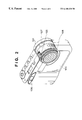
- FIG. 2 is a perspective view of a digital camera according to an embodiment of the present invention.
- FIG. 3A is a top view of a lens cover used in the camera shown in FIG. 2;
- FIG. 3B is a bottom view of the lens cover used in the camera shown in FIG. 2;
- FIG. 4A is a partial sectional view of the lens cover shown in FIGS. 3A and 3B;
- FIG. 4B shows an example of a print condition setup image obtained by the lens cover shown in FIGS. 3A and 3B;
- FIG. 5 is a flow chart showing the operation of the digital camera
- FIG. 6 is a perspective view of a closeup adapter according to the second embodiment of the present invention.
- FIG. 7 is a plan view for explaining the shape of the sheet to be inserted into the adapter shown in FIG. 6;
- FIG. 8 is a plan view for explaining another shape of the sheet to be inserted into the adapter shown in FIG. 6 .
- FIG. 1 shows the basic arrangement of a printing system according to the present invention.
- reference numeral 100 denotes a digital camera
- 200 a printer of, for example, an ink-jet scheme
- 150 an interface cable for connecting the camera 100 and printer 200 .
- the interface cable 150 may use, for example, a known RS 232 interface cable.
- the printer 200 has an interface function that can interpret an existing print condition setup protocol. Note that the print condition setup protocol is used for setting the print conditions of the printer 200 , and a conventional protocol for setting the print conditions between a PC (not shown) and the printer may be used in this embodiment.
- the following seven parameters can be set:
- Paper Setup A 4 portrait, B 5 portrait, postcard, and the like.
- balance conditions for cyan, magenta, yellow, and black can be set.
- reference numeral 300 denotes a known PC.
- the PC is not necessary for setting the print conditions.
- the camera 100 used in the system of the present invention supports two protocols, i.e., a camera setup protocol used for setting the print conditions for directly outputting an image to the printer 200 , and a PC setup protocol for setting the print conditions via the PC 300 .
- the user can select one of these protocols by setting a mode switch 101 at a direct or indirect position.
- the PC setup protocol is the existing one; the camera 100 need only send an image to the PC, and the user sets the print conditions via an application program on the PC.
- the PC sends data pertaining to the print conditions to the printer to set them in the printer, and then sends image data to be printed.
- the camera 100 sends data pertaining to the print conditions to the printer to set them in the printer, and then sends image data to be printed to the printer 200 .
- the print conditions are optically captured by the camera 100 .
- such setups are optically readably made, and an optical image representing the set conditions is converted into an electronic image by a CCD (not shown) via a lens barrel 102 including an image sensing lens as in a normal image sensing mode.
- the camera 100 comprises a recognition unit 104 for recognizing the set print conditions from the electronic image.
- the recognition unit 104 converts the recognition result into a known print condition setup command, and sends the command to the printer 200 via the interface cable 150 in the camera setup protocol.
- the recognition unit 104 of the camera 100 sets the print conditions based on the condition setup image.
- the recognition unit 104 may be arranged in the printer 200 .
- the camera 100 sends the condition setup image to the printer 200 as an image, and the recognition unit 104 of the printer recognizes the print conditions based on the received image.
- FIG. 2 shows the arrangement of the camera 100 used in the system of this embodiment.
- reference numeral 100 denotes a digital camera main body; 106 , a shutter button; 107 , a finder & lens section of the digital camera; and 108 , a black lens cover.
- This cover 108 has a projection 105 for driving the mode switch 101 .
- the cover 108 is a dedicated detachable cover used for setting the print conditions, and is formed with a plurality of print condition setup holes used for setting the print conditions.
- FIG. 3A shows the top surface of the cover 108
- FIG. 3B shows its rear surface.
- reference numeral 111 denotes a condition setup items display area, on which letters that represent condition setup items are printed to be read by the user.
- Reference numeral 110 denotes a plurality of round holes; and 112 , a slit which is elongated in the vertical direction (up-and-down direction in FIG. 3 A). The round holes 110 and slit pass external visible light therethrough, which then enters the lens barrel 107 .
- a plurality of round holes 110 are formed in the horizontal direction in units of items of the print conditions, and details of the print conditions are assigned in advance to the individual round hole positions.
- a plurality of grooves for receiving opaque, plastic slide blocks 109 are formed in the cover 108 .
- ten slide blocks are prepared.
- FIG. 4A is a sectional view of the cover 108 .
- the cover 108 is formed of black plastic, and a plurality of hollow grooves 130 a , 130 b , 130 c , 130 d , . . . partitioned by opaque, black plastic members 122 a , 122 b , 122 c , . . . are formed in the cover 108 , as shown in FIG. 4 A.
- These hollow grooves extend in a direction perpendicular to the plane of the drawing of FIG. 4A, and in the right-and-left direction in FIG. 3 A.
- the vertical position of each hollow groove in the cover 108 corresponds to that of the hole 110 .
- These hollow grooves 130 a, 130 b , 130 c , 130 d , . . . receive slide blocks 109 a , 109 b , 109 c , 109 d , . . . , and when the user moves these slide blocks to the right or left, the blocks slide in the respective hollow grooves.
- the slide blocks 109 a , 109 c , and 109 d of the slide blocks 109 a , 109 b , 109 c , and 109 d reach the other-end portions of the hollow grooves 130 a , 130 c , and 130 d , and only the slide block 109 b does not reach the end of the hollow groove 130 b .
- external light passes through the print condition setup holes 110 corresponding to the hollow groove 130 b , and reaches the CCD (not shown).
- the print condition setup holes corresponding to the hollow grooves 130 a , 130 c , and 130 d are filled with the slide blocks 109 a , 109 c , and 109 d , the external light is intercepted by these blocks. Therefore, when the user presses the shutter button, light is projected onto pixels on the CCD corresponding to the holes and slit which are not closed by the slide blocks, thus obtaining a print condition setup image.
- FIG. 4B shows an example of the print condition setup image obtained when the user appropriately sets the slide blocks 109 .
- the print condition setup image is binarized by recognition (to be described later), and each hole position gives one of two pieces of print condition setup information when it is open or closed.
- the user When the user sets the print output conditions, he or she horizontally slides desired slide blocks 109 on the cover 108 and stops them at given positions to conceal the target holes 110 and slit portions 112 . Then, the user attaches the dedicated condition setup lens cover 108 to the camera.
- control sequence of the internal control program of the digital camera 100 of this embodiment will be explained below with reference to the flow chart in FIG. 5 .
- This control sequence is executed by an internal CPU of the camera shown in FIG. 1, and its protocol is stored in a memory (MEM).
- MEM memory
- step S 100 and the subsequent steps in FIG. 5 are executed. More specifically, the control waits in step S 102 until the user presses a “direct print switch” 111 . Upon depression of this switch, step S 104 is executed. That is, the print condition setup process of this camera is started when the user attaches the cover 108 and presses the switch 111 . In other words, since the switch 111 is arranged, attachment of the dedicated cover 108 does not directly trigger the print condition setups, and can also serve as a normal lens cover.
- step S 104 the control waits until the user presses the shutter 106 .
- the camera captures the print condition setup image by normal image sensing, and stores it in its internal memory (MEM), in step S 106 .
- MEM internal memory
- the camera may roughly read (pre-scan) the image on the lens cover 108 to recognize the data start position.
- the captured print condition setup image is passed to the recognition unit instep S 108 .
- the print condition setup image is binarized and interpreted by the recognition unit, thus recognizing the print conditions.
- the recognized print conditions are converted into a known print condition setup command format.
- step S 110 the already sensed object image data recorded in the memory and the print condition data obtained in step S 108 are simultaneously sent to the printer.
- the print condition setup command is sent to the printer first, and then, the sensed object image data is sent thereto.
- the printer Upon reception of the print condition setup command, the printer sets the print conditions, and then prints the received image.
- the digital camera and printer such as an ink-jet printing apparatus are directly connected, and the print conditions can be set by simple operation, a simple, low-cost printing system for printing an image sensed by the digital camera using the ink-jet printer can be realized while making the digital camera main body compact.
- printer 200 may recognize the print conditions from the print condition setup image, as described above.
- a backlight may be arranged in correspondence with the holes 110 and slit, and may be used as a light source.
- the first embodiment is directed to the print condition setup method using only the lens cover of the digital camera. Since the lens cover has a small area, the number of types of conditions that can be set is limited. For this reason, the second embodiment uses a sheet which can set more condition items than the lens cover.
- the second embodiment requires an adapter for attaching the sheet. As this adapter, a normal closeup adapter may be used. However, in consideration of convenience upon exchanging the sheet, the adapter is prepared by forming a sheet attachment groove on a normal closeup adapter, so that it can be used for both the closeup and sheet attachment purposes.
- FIG. 6 shows the outer appearance of a closeup/print condition setup adapter 400 .
- reference numeral 410 denotes a groove, which receives a print condition setup sheet. With this groove, various types of sheets can be exchangeably set.
- the length of the adapter 400 is determined so that the image on the sheet surface inserted into the sheet groove 410 is formed on the CCD.
- FIG. 7 is a plan view of a condition setup sheet 411 .
- Many temporary holes 412 are formed on the sheet 411 . Since perforations 413 are formed on each temporary hole, an actual hole can be easily formed.
- the control sequence of the second embodiment is substantially the same as that in the first embodiment. More specifically, the user attaches the print condition setup adapter 400 to the digital camera 100 , and inserts the sheet 411 set with the print conditions into the condition setup sheet groove 410 . The camera 100 senses the image on that sheet, and writes the image data in the memory.
- printer may recognize the print conditions from the print condition setup image as in the modification of the first embodiment.
- print conditions can be set by a simple method in addition to the effect of the first embodiment, and the degree of freedom in print condition setups can be greatly improved.
- temporary holes on the sheet may be formed by means other than perforations.
- the user may form a hole with a tool having a sharp distal end.
- the print conditions may be set using marks.
- FIG. 8 shows the shape of a sheet according to that modification, and many marks ⁇ are printed. That is, this sheet is a mark-sheet type print condition setup sheet. The user fills the mark corresponding to the item to be set ( ⁇ ).
- the print conditions sensed as binary data is recorded on a memory, and both the sensed image data to be printed, and print conditions are transferred to an ink-jet recording apparatus (not shown) via a cable, or infrared ray communication means or the like.
- the ink-jet printing apparatus prints out a photograph image under the designated print conditions.
- a printing system for printing an image sensed by the digital camera a system as a combination of the digital camera and ink-jet printing apparatus (including all the types of ink-jet printing apparatuses called on-demand ink-jet type, thermal ink-jet type, non-impact bubble-jet type, and the like) has been described.
- the present invention can be applied to other low-cost printing apparatuses such as a sublimation thermal transfer type that can attain gradation expression by temperature, molten thermal transfer type using dry inks, and the like as inexpensive printing apparatuses which can be easily operated by the user.
- the present invention can be applied to a color laser printer, which is expected to become less expensive in the future, although it is not popular since it is rather expensive currently.
- the digital camera used in this system not only a dedicated digital camera but also a hybrid digital camera such as a still image digital camera built in a video camera using a DVC (digital video cassette) may be used.
- a hybrid digital camera such as a still image digital camera built in a video camera using a DVC (digital video cassette) may be used.
- the interface is not limited to the one using a cable.
- an interface using infrared rays, radio waves, or the like may be used.
- print condition items are assigned to the individual holes or marks.
- the present invention is not limited to this.
- binary values may be given to the individual holes or marks, and each print condition item may be assigned by a decimal value of the binary values of a plurality of open holes.
Abstract
There is disclosed a digital camera in which a lens cover formed with a plurality of holes is attached to a lens barrel. Different items of the print conditions are assigned to the individual holes. The camera senses these holes formed on the cover, recognizes the print conditions based on the sensed image, and transmits the recognized condition to a printing apparatus as print condition data.
Description
The present invention relates to a printing system which can directly connect a digital camera and a printing apparatus, and allows the printing apparatus to directly print an image sensed by the digital camera, and also to a digital camera and printing apparatus.
Conventionally, the simplest way to print out an image sensed by a digital camera as a picture is to capture the sensed image into a PC (personal computer) via a predetermined cable if the image is recorded on an internal memory of the camera or via a PC card slot or the like arranged in the PC if the image is recorded on a PC card or the like, and to print out that image after the print conditions for an ink-jet printer (printing apparatus) are set on the PC. More specifically, the PC is interposed between the camera and printer, and the print conditions are set on that PC.
As a method of setting the print conditions upon printing an image sensed by the digital camera, conventional methods that do not use any PC are also available. For example, in one method, a dedicated adapter and TV monitor are inserted between the digital camera and ink-jet printer, and the print conditions for the ink-jet printer are set on that TV monitor. In another method, a dedicated adapter is inserted between the digital camera and ink-jet printer, and the print conditions for the ink-jet printer are set on a built-in liquid crystal monitor of the digital camera.
However, in the conventional method of capturing an image recorded in the digital camera into the PC, since intervention of the PC is required only for the purpose of setting the print conditions for the ink-jet printer, the operator of the ink-jet printer cannot directly print out the sensed image in a desired mode pertaining to the paper size, image quality, and the like.
Also, when the monitor is used only for the purpose of setting the print conditions, setups on the monitor are cumbersome. Furthermore, when the liquid crystal monitor is equipped in the digital camera, a size reduction of the digital camera cannot be attained.
When a dedicated intervening device is used, it requires high cost.
It is an object of the present invention to provide a system, which can directly connect a digital camera and printer via a predetermined interface, and can set print conditions to directly print an image in the digital camera using the printer.
In order to achieve the above object, there is provided a system for directly printing an image stored in a digital camera using a printer, comprising:
the digital camera having a reader optically reading a member that contains a print condition in the printing apparatus;
a recognizer recognizing the print condition from a read print condition image;
a predetermined interface for directly connecting the digital camera and a predetermined printing apparatus; and
the printer for setting the print condition sent via the interface, and printing a sensed image sent from the digital camera in accordance with the set print condition.
More specifically, the camera comprises image sensing means, which obtains the print condition setup image.
It is another object of the present invention to provide a digital camera which can set print conditions to directly print the sensed image using an external printer.
In order to achieve the above object, there is provided a digital camera which can store a digital image obtained by sensing an object, comprising:
a reader optically reading a member that contains a print condition upon printing an image;
a recognizer recognizing the print condition from a read print condition image; and
an interface for sending data pertaining to the recognized print condition to an external printing apparatus.
More specifically, the camera recognizes data pertaining to the print conditions from a print condition image, and sends that print condition data to the printer.
The printer may also recognize the print conditions from the print condition image. It is, therefore, still another object of the present invention to provide a digital camera which can set print conditions, capture the set print conditions as an image, and send the print condition image to the printer. That is, there is provided a digital camera which can store a digital image obtained by sensing an object, comprising:
a reader optically reading a member that contains a print condition; and
an interface for sending a read print condition image to a printing apparatus.
It is still another object of the present invention to provide a digital camera which has a lens cover formed with a plurality of openings used for setting the print conditions.
It is still another object of the present invention to provide a digital camera which can capture the set print conditions as an image, and has a switch for selecting whether or not the print condition image is to be sent to the printing apparatus.
It is still another object of the present invention to provide a digital camera which can capture the set print conditions as an image, and comprises a protocol for setting in cooperation with the printer whether or not the print condition image is to be sent to the printer.
It is still another object of the present invention to provide a digital camera which has a lens cover formed with a plurality of openings used for setting the print conditions.
The camera of the present invention has various aspects as follows.
According to a preferred aspect of the present invention, the reader comprises:
a lens cover which serves as the member, and is formed with a plurality of openings, each of which passes light therethrough and is free to open/close;
a lens casing to which the lens cover is to be attached;
a CCD converting light passing through a lens into an image signal; and
a memory storing the image signal.
According to a preferred aspect of the present invention, the reader comprises:
a sheet which serves as the member, and can be formed with holes that pass light therethrough;
a lens adapter which can receive the sheet;
a lens casing to which the lens adapter is to be attached;
a CCD for converting light passing through a lens into an image signal; and
a memory for storing the image signal.
According to a preferred aspect of the present invention, the camera further comprises:
a switch which is closed upon depression; and
a control program for setting the camera in a print condition setup mode when the switch is closed,
wherein the member has an actuator for energizing the switch when the member is attached to a front end of a lens barrel of the camera.
According to a preferred aspect of the present invention, the camera further compries a start switch operated by a user to start external transfer of data pertaining to the recognized print condition.
According to a preferred aspect of the present invention, the camera has:
a first mode for making an external controller set the print condition in a printing apparatus; and
a second mode for directly setting the print condition in the printing apparatus on the basis of a print condition setup image, and
the camera further comprises a mode switch, which is energized when the member is attached to the camera, and sets the camera in the second mode when the switch is closed.
According to a preferred aspect of the present invention, the member comprises:
a plurality of holes which are assigned predetermined items of the print conditions, are aligned in a first direction, and are free to open/close; and
a slide member which is slidable along the plurality of holes and closes some or all of the plurality of holes.
According to a preferred aspect of the present invention, the member comprises:
a plurality of holes which are assigned predetermined items of the print conditions, are aligned in a first direction, and are free to open/close.
According to a preferred aspect of the present invention, the member comprises:
a plurality of marks which are assigned predetermined items of the print conditions, and are aligned in a first direction, and
the marks can be painted by a user.
According to a preferred aspect of the present invention, the reader comprises:
a sheet which serves as the member, and on which a mark can be written;
a lens adapter which can receive the sheet;
a lens casing to which the lens adapter is to be attached;
a CCD for converting light passing through a lens into an image signal; and
a memory for storing the image signal.
According to a preferred aspect of the present invention, a plurality of temporary holes which can be changed into actual holes by perforations are formed on the member.
Other features and advantages of the present invention will be apparent from the following description taken in conjunction with the accompanying drawings, in which like reference characters designate the same or similar parts throughout the figures thereof.
FIG. 1 is a block diagram showing the arrangement of a digital camera/printer system according to the present invention;
FIG. 2 is a perspective view of a digital camera according to an embodiment of the present invention;
FIG. 3A is a top view of a lens cover used in the camera shown in FIG. 2;
FIG. 3B is a bottom view of the lens cover used in the camera shown in FIG. 2;
FIG. 4A is a partial sectional view of the lens cover shown in FIGS. 3A and 3B;
FIG. 4B shows an example of a print condition setup image obtained by the lens cover shown in FIGS. 3A and 3B;
FIG. 5 is a flow chart showing the operation of the digital camera;
FIG. 6 is a perspective view of a closeup adapter according to the second embodiment of the present invention;
FIG. 7 is a plan view for explaining the shape of the sheet to be inserted into the adapter shown in FIG. 6; and
FIG. 8 is a plan view for explaining another shape of the sheet to be inserted into the adapter shown in FIG. 6.
The preferred embodiments of the present invention will be explained hereinafter with reference to the accompanying drawings.
<System Arrangement>
FIG. 1 shows the basic arrangement of a printing system according to the present invention. Referring to FIG. 1, reference numeral 100 denotes a digital camera; 200, a printer of, for example, an ink-jet scheme; and 150, an interface cable for connecting the camera 100 and printer 200.
The interface cable 150 may use, for example, a known RS232 interface cable. Also, the printer 200 has an interface function that can interpret an existing print condition setup protocol. Note that the print condition setup protocol is used for setting the print conditions of the printer 200, and a conventional protocol for setting the print conditions between a PC (not shown) and the printer may be used in this embodiment.
In this embodiment, as the print conditions, the following seven parameters can be set:
Printer type (thermal ink-jet or bubble-jet)
Print mode (vertical printing, horizontal printing)
Paper Setup (A4 portrait, B5 portrait, postcard, and the like)
Print direction (one-way or two-way)
Print quality (fine, draft)
Density (dark, light)
Color correction
Especially, as for the color correction conditions, balance conditions for cyan, magenta, yellow, and black can be set.
Referring back to FIG. 1, reference numeral 300 denotes a known PC. In this embodiment, the PC is not necessary for setting the print conditions. The camera 100 used in the system of the present invention supports two protocols, i.e., a camera setup protocol used for setting the print conditions for directly outputting an image to the printer 200, and a PC setup protocol for setting the print conditions via the PC 300. The user can select one of these protocols by setting a mode switch 101 at a direct or indirect position.
The PC setup protocol is the existing one; the camera 100 need only send an image to the PC, and the user sets the print conditions via an application program on the PC. The PC sends data pertaining to the print conditions to the printer to set them in the printer, and then sends image data to be printed.
In the camera setup protocol, the camera 100 sends data pertaining to the print conditions to the printer to set them in the printer, and then sends image data to be printed to the printer 200.
In FIG. 1, when the camera setup protocol is used, the print conditions are optically captured by the camera 100. As will be described later, such setups are optically readably made, and an optical image representing the set conditions is converted into an electronic image by a CCD (not shown) via a lens barrel 102 including an image sensing lens as in a normal image sensing mode. The camera 100 comprises a recognition unit 104 for recognizing the set print conditions from the electronic image. The recognition unit 104 converts the recognition result into a known print condition setup command, and sends the command to the printer 200 via the interface cable 150 in the camera setup protocol.
In the system shown in FIG. 1, the recognition unit 104 of the camera 100 sets the print conditions based on the condition setup image. Alternatively, the recognition unit 104 may be arranged in the printer 200. In this case, the camera 100 sends the condition setup image to the printer 200 as an image, and the recognition unit 104 of the printer recognizes the print conditions based on the received image.
<Camera Arrangement> . . . First Embodiment
FIG. 2 shows the arrangement of the camera 100 used in the system of this embodiment.
Referring to FIG. 2, reference numeral 100 denotes a digital camera main body; 106, a shutter button; 107, a finder & lens section of the digital camera; and 108, a black lens cover. This cover 108 has a projection 105 for driving the mode switch 101.
The cover 108 is a dedicated detachable cover used for setting the print conditions, and is formed with a plurality of print condition setup holes used for setting the print conditions. FIG. 3A shows the top surface of the cover 108, and FIG. 3B shows its rear surface.
In FIG. 3A, reference numeral 111 denotes a condition setup items display area, on which letters that represent condition setup items are printed to be read by the user. Reference numeral 110 denotes a plurality of round holes; and 112, a slit which is elongated in the vertical direction (up-and-down direction in FIG. 3A). The round holes 110 and slit pass external visible light therethrough, which then enters the lens barrel 107.
In the example shown in FIG. 3A, a plurality of round holes 110 (eight holes per item) are formed in the horizontal direction in units of items of the print conditions, and details of the print conditions are assigned in advance to the individual round hole positions.
Also, a plurality of grooves for receiving opaque, plastic slide blocks 109 are formed in the cover 108. In the example in FIG. 3A, since there are ten print condition items, ten slide blocks are prepared.
FIG. 4A is a sectional view of the cover 108. As described above, the cover 108 is formed of black plastic, and a plurality of hollow grooves 130 a, 130 b, 130 c, 130 d, . . . partitioned by opaque, black plastic members 122 a, 122 b, 122 c, . . . are formed in the cover 108, as shown in FIG. 4A. These hollow grooves extend in a direction perpendicular to the plane of the drawing of FIG. 4A, and in the right-and-left direction in FIG. 3A. The vertical position of each hollow groove in the cover 108 corresponds to that of the hole 110. These hollow grooves 130 a, 130 b, 130 c, 130 d, . . . receive slide blocks 109 a, 109 b, 109 c, 109 d, . . . , and when the user moves these slide blocks to the right or left, the blocks slide in the respective hollow grooves.
In the example in FIG. 4A, the slide blocks 109 a, 109 c, and 109 d of the slide blocks 109 a, 109 b, 109 c, and 109 d reach the other-end portions of the hollow grooves 130 a, 130 c, and 130 d, and only the slide block 109 b does not reach the end of the hollow groove 130 b. Hence, external light passes through the print condition setup holes 110 corresponding to the hollow groove 130 b, and reaches the CCD (not shown). On the other hand, since the print condition setup holes corresponding to the hollow grooves 130 a, 130 c, and 130 d are filled with the slide blocks 109 a, 109 c, and 109 d, the external light is intercepted by these blocks. Therefore, when the user presses the shutter button, light is projected onto pixels on the CCD corresponding to the holes and slit which are not closed by the slide blocks, thus obtaining a print condition setup image.
FIG. 4B shows an example of the print condition setup image obtained when the user appropriately sets the slide blocks 109. The print condition setup image is binarized by recognition (to be described later), and each hole position gives one of two pieces of print condition setup information when it is open or closed.
When the user sets the print output conditions, he or she horizontally slides desired slide blocks 109 on the cover 108 and stops them at given positions to conceal the target holes 110 and slit portions 112. Then, the user attaches the dedicated condition setup lens cover 108 to the camera.
The control sequence of the internal control program of the digital camera 100 of this embodiment will be explained below with reference to the flow chart in FIG. 5. This control sequence is executed by an internal CPU of the camera shown in FIG. 1, and its protocol is stored in a memory (MEM).
When the user attaches the dedicated print condition setup lens cover 108 set with the print conditions to the camera, the projection (stopper) 105 of the cover 108 presses the switch 101. Upon depression of the switch 101, step S100 and the subsequent steps in FIG. 5 are executed. More specifically, the control waits in step S102 until the user presses a “direct print switch” 111. Upon depression of this switch, step S104 is executed. That is, the print condition setup process of this camera is started when the user attaches the cover 108 and presses the switch 111. In other words, since the switch 111 is arranged, attachment of the dedicated cover 108 does not directly trigger the print condition setups, and can also serve as a normal lens cover.
In step S104, the control waits until the user presses the shutter 106. When the user has pressed the shutter 106, the camera captures the print condition setup image by normal image sensing, and stores it in its internal memory (MEM), in step S106.
In this case, when binary data is captured by the digital camera 100, the camera may roughly read (pre-scan) the image on the lens cover 108 to recognize the data start position.
The captured print condition setup image is passed to the recognition unit instep S108. The print condition setup image is binarized and interpreted by the recognition unit, thus recognizing the print conditions. The recognized print conditions are converted into a known print condition setup command format.
In step S110, the already sensed object image data recorded in the memory and the print condition data obtained in step S108 are simultaneously sent to the printer. Alternatively, the print condition setup command is sent to the printer first, and then, the sensed object image data is sent thereto.
Upon reception of the print condition setup command, the printer sets the print conditions, and then prints the received image.
In this way, according to the first embodiment, since the digital camera and printer such as an ink-jet printing apparatus are directly connected, and the print conditions can be set by simple operation, a simple, low-cost printing system for printing an image sensed by the digital camera using the ink-jet printer can be realized while making the digital camera main body compact.
Note that the printer 200 may recognize the print conditions from the print condition setup image, as described above.
Upon forming the condition setup image, natural light is used in the above embodiment. Alternatively, a backlight may be arranged in correspondence with the holes 110 and slit, and may be used as a light source.
<Camera Arrangement> . . . Second Embodiment
The second embodiment of a digital camera according to the present invention will be described below with reference to the accompanying drawings.
The first embodiment is directed to the print condition setup method using only the lens cover of the digital camera. Since the lens cover has a small area, the number of types of conditions that can be set is limited. For this reason, the second embodiment uses a sheet which can set more condition items than the lens cover. The second embodiment requires an adapter for attaching the sheet. As this adapter, a normal closeup adapter may be used. However, in consideration of convenience upon exchanging the sheet, the adapter is prepared by forming a sheet attachment groove on a normal closeup adapter, so that it can be used for both the closeup and sheet attachment purposes.
Note that the camera of the second embodiment is substantially the same as the digital camera shown in FIG. 2. FIG. 6 shows the outer appearance of a closeup/print condition setup adapter 400. In FIG. 6, reference numeral 410 denotes a groove, which receives a print condition setup sheet. With this groove, various types of sheets can be exchangeably set.
Note that the length of the adapter 400 is determined so that the image on the sheet surface inserted into the sheet groove 410 is formed on the CCD.
FIG. 7 is a plan view of a condition setup sheet 411. Many temporary holes 412 are formed on the sheet 411. Since perforations 413 are formed on each temporary hole, an actual hole can be easily formed.
The control sequence of the second embodiment is substantially the same as that in the first embodiment. More specifically, the user attaches the print condition setup adapter 400 to the digital camera 100, and inserts the sheet 411 set with the print conditions into the condition setup sheet groove 410. The camera 100 senses the image on that sheet, and writes the image data in the memory.
The subsequent control processes are the same as those in the first embodiment.
Note that the printer may recognize the print conditions from the print condition setup image as in the modification of the first embodiment.
To recapitulate, according to the second embodiment, more print conditions can be set by a simple method in addition to the effect of the first embodiment, and the degree of freedom in print condition setups can be greatly improved.
<Modification>
As for the sheet of the second embodiment, temporary holes on the sheet may be formed by means other than perforations. For example, the user may form a hole with a tool having a sharp distal end.
In the second embodiment, the print conditions may be set using marks. FIG. 8 shows the shape of a sheet according to that modification, and many marks ◯ are printed. That is, this sheet is a mark-sheet type print condition setup sheet. The user fills the mark corresponding to the item to be set (◯→).
The print conditions sensed as binary data is recorded on a memory, and both the sensed image data to be printed, and print conditions are transferred to an ink-jet recording apparatus (not shown) via a cable, or infrared ray communication means or the like. The ink-jet printing apparatus prints out a photograph image under the designated print conditions.
<Another Embodiment>
In the above description, as a printing system for printing an image sensed by the digital camera, a system as a combination of the digital camera and ink-jet printing apparatus (including all the types of ink-jet printing apparatuses called on-demand ink-jet type, thermal ink-jet type, non-impact bubble-jet type, and the like) has been described. Also, the present invention can be applied to other low-cost printing apparatuses such as a sublimation thermal transfer type that can attain gradation expression by temperature, molten thermal transfer type using dry inks, and the like as inexpensive printing apparatuses which can be easily operated by the user. Furthermore, the present invention can be applied to a color laser printer, which is expected to become less expensive in the future, although it is not popular since it is rather expensive currently.
As for the digital camera used in this system, not only a dedicated digital camera but also a hybrid digital camera such as a still image digital camera built in a video camera using a DVC (digital video cassette) may be used.
The interface is not limited to the one using a cable. For example, an interface using infrared rays, radio waves, or the like may be used.
In the above embodiments, print condition items are assigned to the individual holes or marks. However, the present invention is not limited to this. For example, binary values may be given to the individual holes or marks, and each print condition item may be assigned by a decimal value of the binary values of a plurality of open holes.
As many apparently widely different embodiments of the present invention can be made without departing from the spirit and scope thereof, it is to be understood that the invention is not limited to the specific embodiments thereof except as defined in the appended claims.
Claims (11)
1. A digital camera which can store a digital image obtained by sensing an object, comprising:
a reader for optically reading a member that contains at least one print condition upon printing an image;
a recognizer recognizing the print conditions form a read print condition image;
an interface for sending data pertaining to the recognized print condition to an external printing apparatus;
a switch which is closed upon depression; and
a control program for setting said camera in a print condition setup mode when said switch is closed,
wherein said member has an actuator for energizing said switch when said member is attached to a front end of a lens barrel of said camera.
2. The camera according to claim 1, wherein said reader comprises:
a lens cover which serves as said member, and is formed with a plurality of openings, each of which passes light therethrough and is free to open/close;
a lens casing to which said lens cover is to be attached;
a CCD for converting light passing through a lens into an image signal; and
a memory for storing the image signal.
3. The camera according to claim 1, wherein said reader comprises:
a sheet which serves as said member, and can be formed with holes that pass light therethrough;
a lens adapter which can receive said sheet;
a lens casing to which said lens adapter is to be attached;
a CCD for converting light passing through a lens into an image signal; and
a memory storing the image signal.
4. The camera according to claim 1, further comprising:
a start switch operated by a user to start external transfer of data pertaining to the recognized print condition.
5. The camera according to claim 1, wherein said camera
a first mode for making an external controller set the print condition in a printer; and
a second mode for directly setting the print condition in the printer on the basis of a print condition setup image, and
said camera further comprises a mode switch, which is energized when a member is attached to a camera, and sets said camera in the second mode when said switch is closed.
6. The camera according to claim 1, wherein said member comprises:
a plurality of holes which are assigned predetermined items of the print conditions, are aligned in a first direction, and are free to open/close; and
a slide member which is slidable along said plurality of holes and closes some or all of said plurality of holes.
7. The camera according to claim 1, wherein said member comprises:
a plurality of holes which are assigned predetermined items of the print conditions, are aligned in a first direction, and are free to open/close.
8. The camera according to claim 1, wherein said member comprises:
a plurality of marks which are assigned predetermined items of the print conditions, and are aligned in a first direction, and
said marks can be painted by a user.
9. The camera according to claim 1, wherein said reader comprises:
a sheet which serves as said member, and on which a mark can be written;
a lens adapter which can receive said sheet;
a lens casing to which said lens adapter is to be attached;
a CCD converting light passing through a lens into an image signal; and
a memory storing the image signal.
10. The camera according to claim 1, wherein a plurality of temporary holes which can be changed into actual holes by perforations are formed on said member.
11. The camera according to claim 1, wherein the printing apparatus comprises an ink-jet printing apparatus for printing an image by ejecting ink in a detachable ink cartridge via a nozzle.
Applications Claiming Priority (2)
| Application Number | Priority Date | Filing Date | Title |
|---|---|---|---|
| JP9115082A JPH10294918A (en) | 1997-04-18 | 1997-04-18 | Digital camera and ink jet recorder |
| JP9-115082 | 1997-04-18 |
Publications (1)
| Publication Number | Publication Date |
|---|---|
| US6188430B1 true US6188430B1 (en) | 2001-02-13 |
Family
ID=14653749
Family Applications (1)
| Application Number | Title | Priority Date | Filing Date |
|---|---|---|---|
| US09/060,098 Expired - Fee Related US6188430B1 (en) | 1997-04-18 | 1998-04-14 | Digital camera and ink-jet printing apparatus |
Country Status (2)
| Country | Link |
|---|---|
| US (1) | US6188430B1 (en) |
| JP (1) | JPH10294918A (en) |
Cited By (24)
| Publication number | Priority date | Publication date | Assignee | Title |
|---|---|---|---|---|
| US6520631B1 (en) | 1998-11-09 | 2003-02-18 | Silverbrook Research Pty Ltd | Cartridge for a sticker printing digital camera device |
| US6539180B1 (en) * | 1998-11-09 | 2003-03-25 | Silverbrook Research Pty Ltd | Print on demand camera system incorporating a detachable printing unit |
| US20030063908A1 (en) * | 1998-11-09 | 2003-04-03 | Kia Silverbrook | Image processor with integrated printing |
| US20030117453A1 (en) * | 2001-05-09 | 2003-06-26 | Canon Kabushiki Kaisha | Inkjet recording method, inkjet recording apparatus, program and storage medium storing program code readable by computer |
| US6765686B2 (en) * | 1997-11-14 | 2004-07-20 | Canon Kabushiki Kaisha | Image processing apparatus, method of controlling same, and image processing system |
| US6788336B1 (en) * | 1997-07-15 | 2004-09-07 | Silverbrook Research Pty Ltd | Digital camera with integral color printer and modular replaceable print roll |
| US20040183936A1 (en) * | 2003-03-18 | 2004-09-23 | Young-Jun Kim | Digital camera module, apparatus and method of assembling the same |
| US20040233267A1 (en) * | 1998-11-09 | 2004-11-25 | Kia Silverbrook | Image recordal and generation apparatus |
| US7014307B2 (en) | 1998-11-09 | 2006-03-21 | Silverbrook Research Pty Ltd | Printing unit for an image recordal and generation apparatus |
| US20100194923A1 (en) * | 1997-07-15 | 2010-08-05 | Silverbrook Research Pty Ltd | Digital camera having interconnected image processing units |
| US20100208085A1 (en) * | 1997-07-15 | 2010-08-19 | Silverbrook Research Pty Ltd | Digital camera for processing and printing images |
| US20100253791A1 (en) * | 1997-07-15 | 2010-10-07 | Silverbrook Research Pty Ltd | Camera sensing device for capturing and manipulating images |
| US8013905B2 (en) | 1997-07-15 | 2011-09-06 | Silverbrook Research Pty Ltd | Method of processing images captured by digital camera to reduce distortion |
| US20110216332A1 (en) * | 1997-07-15 | 2011-09-08 | Silverbrook Research Pty Ltd | System for creating garments using camera and encoded card |
| US20110228026A1 (en) * | 1997-07-15 | 2011-09-22 | Silverbrook Research Pty Ltd | Digital camera system for simultaneous printing and magnetic recording |
| US8096642B2 (en) | 1997-08-11 | 2012-01-17 | Silverbrook Research Pty Ltd | Inkjet nozzle with paddle layer arranged between first and second wafers |
| US8274665B2 (en) | 1997-07-15 | 2012-09-25 | Silverbrook Research Pty Ltd | Image sensing and printing device |
| US8421869B2 (en) | 1997-07-15 | 2013-04-16 | Google Inc. | Camera system for with velocity sensor and de-blurring processor |
| US8789939B2 (en) | 1998-11-09 | 2014-07-29 | Google Inc. | Print media cartridge with ink supply manifold |
| US8866923B2 (en) | 1999-05-25 | 2014-10-21 | Google Inc. | Modular camera and printer |
| US8896724B2 (en) | 1997-07-15 | 2014-11-25 | Google Inc. | Camera system to facilitate a cascade of imaging effects |
| US8902333B2 (en) | 1997-07-15 | 2014-12-02 | Google Inc. | Image processing method using sensed eye position |
| US8908075B2 (en) | 1997-07-15 | 2014-12-09 | Google Inc. | Image capture and processing integrated circuit for a camera |
| US8936196B2 (en) | 1997-07-15 | 2015-01-20 | Google Inc. | Camera unit incorporating program script scanner |
Families Citing this family (1)
| Publication number | Priority date | Publication date | Assignee | Title |
|---|---|---|---|---|
| CN1190735C (en) * | 2002-09-26 | 2005-02-23 | 深圳市朗科科技有限公司 | Data exchange and storing method and device |
Citations (7)
| Publication number | Priority date | Publication date | Assignee | Title |
|---|---|---|---|---|
| US2482242A (en) * | 1948-06-09 | 1949-09-20 | Remington Rand Inc | Code selector |
| US4248528A (en) * | 1979-04-04 | 1981-02-03 | Xerox Corporation | Copier with document sensing control |
| US4757348A (en) * | 1986-11-17 | 1988-07-12 | Xerox Corporation | High speed electronic reprographic/printing machine |
| US5640647A (en) * | 1995-11-27 | 1997-06-17 | Xerox Corporation | Method and apparatus for selectively scanning pages within a document stack |
| US5757388A (en) * | 1996-12-16 | 1998-05-26 | Eastman Kodak Company | Electronic camera and integral ink jet printer |
| US5781708A (en) * | 1994-09-13 | 1998-07-14 | Intermec Technology, Inc. | Integral bar code printer and reader system and method of operation |
| US5903285A (en) * | 1995-10-17 | 1999-05-11 | Samsung Electronics Co., Ltd. | Circuit and method for detecting ink cartridge mounting in ink jet recording apparatus |
-
1997
- 1997-04-18 JP JP9115082A patent/JPH10294918A/en active Pending
-
1998
- 1998-04-14 US US09/060,098 patent/US6188430B1/en not_active Expired - Fee Related
Patent Citations (7)
| Publication number | Priority date | Publication date | Assignee | Title |
|---|---|---|---|---|
| US2482242A (en) * | 1948-06-09 | 1949-09-20 | Remington Rand Inc | Code selector |
| US4248528A (en) * | 1979-04-04 | 1981-02-03 | Xerox Corporation | Copier with document sensing control |
| US4757348A (en) * | 1986-11-17 | 1988-07-12 | Xerox Corporation | High speed electronic reprographic/printing machine |
| US5781708A (en) * | 1994-09-13 | 1998-07-14 | Intermec Technology, Inc. | Integral bar code printer and reader system and method of operation |
| US5903285A (en) * | 1995-10-17 | 1999-05-11 | Samsung Electronics Co., Ltd. | Circuit and method for detecting ink cartridge mounting in ink jet recording apparatus |
| US5640647A (en) * | 1995-11-27 | 1997-06-17 | Xerox Corporation | Method and apparatus for selectively scanning pages within a document stack |
| US5757388A (en) * | 1996-12-16 | 1998-05-26 | Eastman Kodak Company | Electronic camera and integral ink jet printer |
Cited By (103)
| Publication number | Priority date | Publication date | Assignee | Title |
|---|---|---|---|---|
| US8902340B2 (en) | 1997-07-12 | 2014-12-02 | Google Inc. | Multi-core image processor for portable device |
| US9544451B2 (en) | 1997-07-12 | 2017-01-10 | Google Inc. | Multi-core image processor for portable device |
| US9338312B2 (en) | 1997-07-12 | 2016-05-10 | Google Inc. | Portable handheld device with multi-core image processor |
| US8947592B2 (en) | 1997-07-12 | 2015-02-03 | Google Inc. | Handheld imaging device with image processor provided with multiple parallel processing units |
| US8947679B2 (en) | 1997-07-15 | 2015-02-03 | Google Inc. | Portable handheld device with multi-core microcoded image processor |
| US8953060B2 (en) | 1997-07-15 | 2015-02-10 | Google Inc. | Hand held image capture device with multi-core processor and wireless interface to input device |
| US6788336B1 (en) * | 1997-07-15 | 2004-09-07 | Silverbrook Research Pty Ltd | Digital camera with integral color printer and modular replaceable print roll |
| US8836809B2 (en) | 1997-07-15 | 2014-09-16 | Google Inc. | Quad-core image processor for facial detection |
| US9584681B2 (en) | 1997-07-15 | 2017-02-28 | Google Inc. | Handheld imaging device incorporating multi-core image processor |
| US9560221B2 (en) | 1997-07-15 | 2017-01-31 | Google Inc. | Handheld imaging device with VLIW image processor |
| US9432529B2 (en) | 1997-07-15 | 2016-08-30 | Google Inc. | Portable handheld device with multi-core microcoded image processor |
| US9237244B2 (en) | 1997-07-15 | 2016-01-12 | Google Inc. | Handheld digital camera device with orientation sensing and decoding capabilities |
| US9219832B2 (en) | 1997-07-15 | 2015-12-22 | Google Inc. | Portable handheld device with multi-core image processor |
| US9197767B2 (en) | 1997-07-15 | 2015-11-24 | Google Inc. | Digital camera having image processor and printer |
| US9191529B2 (en) | 1997-07-15 | 2015-11-17 | Google Inc | Quad-core camera processor |
| US9191530B2 (en) | 1997-07-15 | 2015-11-17 | Google Inc. | Portable hand-held device having quad core image processor |
| US9185246B2 (en) | 1997-07-15 | 2015-11-10 | Google Inc. | Camera system comprising color display and processor for decoding data blocks in printed coding pattern |
| US9185247B2 (en) | 1997-07-15 | 2015-11-10 | Google Inc. | Central processor with multiple programmable processor units |
| US9179020B2 (en) | 1997-07-15 | 2015-11-03 | Google Inc. | Handheld imaging device with integrated chip incorporating on shared wafer image processor and central processor |
| US9168761B2 (en) | 1997-07-15 | 2015-10-27 | Google Inc. | Disposable digital camera with printing assembly |
| US9148530B2 (en) | 1997-07-15 | 2015-09-29 | Google Inc. | Handheld imaging device with multi-core image processor integrating common bus interface and dedicated image sensor interface |
| US9143635B2 (en) | 1997-07-15 | 2015-09-22 | Google Inc. | Camera with linked parallel processor cores |
| US9143636B2 (en) | 1997-07-15 | 2015-09-22 | Google Inc. | Portable device with dual image sensors and quad-core processor |
| US9137397B2 (en) | 1997-07-15 | 2015-09-15 | Google Inc. | Image sensing and printing device |
| US9137398B2 (en) | 1997-07-15 | 2015-09-15 | Google Inc. | Multi-core processor for portable device with dual image sensors |
| US9131083B2 (en) | 1997-07-15 | 2015-09-08 | Google Inc. | Portable imaging device with multi-core processor |
| US9124737B2 (en) | 1997-07-15 | 2015-09-01 | Google Inc. | Portable device with image sensor and quad-core processor for multi-point focus image capture |
| US9124736B2 (en) | 1997-07-15 | 2015-09-01 | Google Inc. | Portable hand-held device for displaying oriented images |
| US9060128B2 (en) | 1997-07-15 | 2015-06-16 | Google Inc. | Portable hand-held device for manipulating images |
| US8913137B2 (en) | 1997-07-15 | 2014-12-16 | Google Inc. | Handheld imaging device with multi-core image processor integrating image sensor interface |
| US9055221B2 (en) | 1997-07-15 | 2015-06-09 | Google Inc. | Portable hand-held device for deblurring sensed images |
| US20100194923A1 (en) * | 1997-07-15 | 2010-08-05 | Silverbrook Research Pty Ltd | Digital camera having interconnected image processing units |
| US20100208085A1 (en) * | 1997-07-15 | 2010-08-19 | Silverbrook Research Pty Ltd | Digital camera for processing and printing images |
| US8866926B2 (en) | 1997-07-15 | 2014-10-21 | Google Inc. | Multi-core processor for hand-held, image capture device |
| US20100253791A1 (en) * | 1997-07-15 | 2010-10-07 | Silverbrook Research Pty Ltd | Camera sensing device for capturing and manipulating images |
| US8913182B2 (en) | 1997-07-15 | 2014-12-16 | Google Inc. | Portable hand-held device having networked quad core processor |
| US8953061B2 (en) | 1997-07-15 | 2015-02-10 | Google Inc. | Image capture device with linked multi-core processor and orientation sensor |
| US8953178B2 (en) | 1997-07-15 | 2015-02-10 | Google Inc. | Camera system with color display and processor for reed-solomon decoding |
| US7961249B2 (en) | 1997-07-15 | 2011-06-14 | Silverbrook Research Pty Ltd | Digital camera having interconnected image processing units |
| US7969477B2 (en) | 1997-07-15 | 2011-06-28 | Silverbrook Research Pty Ltd | Camera sensing device for capturing and manipulating images |
| US8013905B2 (en) | 1997-07-15 | 2011-09-06 | Silverbrook Research Pty Ltd | Method of processing images captured by digital camera to reduce distortion |
| US20110216332A1 (en) * | 1997-07-15 | 2011-09-08 | Silverbrook Research Pty Ltd | System for creating garments using camera and encoded card |
| US20110228026A1 (en) * | 1997-07-15 | 2011-09-22 | Silverbrook Research Pty Ltd | Digital camera system for simultaneous printing and magnetic recording |
| US8913151B2 (en) | 1997-07-15 | 2014-12-16 | Google Inc. | Digital camera with quad core processor |
| US8102568B2 (en) | 1997-07-15 | 2012-01-24 | Silverbrook Research Pty Ltd | System for creating garments using camera and encoded card |
| US8274665B2 (en) | 1997-07-15 | 2012-09-25 | Silverbrook Research Pty Ltd | Image sensing and printing device |
| US8285137B2 (en) | 1997-07-15 | 2012-10-09 | Silverbrook Research Pty Ltd | Digital camera system for simultaneous printing and magnetic recording |
| US8936196B2 (en) | 1997-07-15 | 2015-01-20 | Google Inc. | Camera unit incorporating program script scanner |
| US8937727B2 (en) | 1997-07-15 | 2015-01-20 | Google Inc. | Portable handheld device with multi-core image processor |
| US8421869B2 (en) | 1997-07-15 | 2013-04-16 | Google Inc. | Camera system for with velocity sensor and de-blurring processor |
| US8934027B2 (en) | 1997-07-15 | 2015-01-13 | Google Inc. | Portable device with image sensors and multi-core processor |
| US8823823B2 (en) | 1997-07-15 | 2014-09-02 | Google Inc. | Portable imaging device with multi-core processor and orientation sensor |
| US8934053B2 (en) | 1997-07-15 | 2015-01-13 | Google Inc. | Hand-held quad core processing apparatus |
| US8928897B2 (en) | 1997-07-15 | 2015-01-06 | Google Inc. | Portable handheld device with multi-core image processor |
| US8922791B2 (en) | 1997-07-15 | 2014-12-30 | Google Inc. | Camera system with color display and processor for Reed-Solomon decoding |
| US8896720B2 (en) | 1997-07-15 | 2014-11-25 | Google Inc. | Hand held image capture device with multi-core processor for facial detection |
| US8896724B2 (en) | 1997-07-15 | 2014-11-25 | Google Inc. | Camera system to facilitate a cascade of imaging effects |
| US8922670B2 (en) | 1997-07-15 | 2014-12-30 | Google Inc. | Portable hand-held device having stereoscopic image camera |
| US8902333B2 (en) | 1997-07-15 | 2014-12-02 | Google Inc. | Image processing method using sensed eye position |
| US8902324B2 (en) | 1997-07-15 | 2014-12-02 | Google Inc. | Quad-core image processor for device with image display |
| US8902357B2 (en) | 1997-07-15 | 2014-12-02 | Google Inc. | Quad-core image processor |
| US8908075B2 (en) | 1997-07-15 | 2014-12-09 | Google Inc. | Image capture and processing integrated circuit for a camera |
| US8908069B2 (en) | 1997-07-15 | 2014-12-09 | Google Inc. | Handheld imaging device with quad-core image processor integrating image sensor interface |
| US8908051B2 (en) | 1997-07-15 | 2014-12-09 | Google Inc. | Handheld imaging device with system-on-chip microcontroller incorporating on shared wafer image processor and image sensor |
| US8096642B2 (en) | 1997-08-11 | 2012-01-17 | Silverbrook Research Pty Ltd | Inkjet nozzle with paddle layer arranged between first and second wafers |
| US6765686B2 (en) * | 1997-11-14 | 2004-07-20 | Canon Kabushiki Kaisha | Image processing apparatus, method of controlling same, and image processing system |
| US7695082B2 (en) | 1998-11-09 | 2010-04-13 | Silverbrook Research Pty Ltd | PCMCIA printing device |
| US7385628B2 (en) | 1998-11-09 | 2008-06-10 | Silverbrook Research Pty Ltd | Camera and print unit with detachable interface |
| US20100225724A1 (en) * | 1998-11-09 | 2010-09-09 | Silverbrook Research Pty Ltd | Printing unit incorporating integrated data connector, media supply cartridge and print head assembly |
| US20050078160A1 (en) * | 1998-11-09 | 2005-04-14 | Kia Silverbrook | PCMCIA printer |
| US20040233267A1 (en) * | 1998-11-09 | 2004-11-25 | Kia Silverbrook | Image recordal and generation apparatus |
| US8789939B2 (en) | 1998-11-09 | 2014-07-29 | Google Inc. | Print media cartridge with ink supply manifold |
| US8337001B2 (en) | 1998-11-09 | 2012-12-25 | Silverbrook Research Pty Ltd | Compact printer with static page width printhead |
| US8282207B2 (en) | 1998-11-09 | 2012-10-09 | Silverbrook Research Pty Ltd | Printing unit incorporating integrated data connector, media supply cartridge and print head assembly |
| US6520631B1 (en) | 1998-11-09 | 2003-02-18 | Silverbrook Research Pty Ltd | Cartridge for a sticker printing digital camera device |
| US20050041106A1 (en) * | 1998-11-09 | 2005-02-24 | King Tobin Allen | Camera and printer having slidably detachable interface |
| US20110090266A1 (en) * | 1998-11-09 | 2011-04-21 | Silverbrook Research Pty Ltd | Compact printer with static page width printhead |
| US7922273B2 (en) | 1998-11-09 | 2011-04-12 | Silverbrook Research Pty Ltd | Card-type printing device |
| US7862143B2 (en) | 1998-11-09 | 2011-01-04 | Silverbrook Research Pty Ltd | Compact printer with static page width printhead |
| US20100188445A1 (en) * | 1998-11-09 | 2010-07-29 | Silverbrook Research Pty Ltd | Card-type printing device |
| US20090027441A1 (en) * | 1998-11-09 | 2009-01-29 | Silverbrook Research Pty Ltd | Compact printer with static page width printhead |
| US7460153B2 (en) | 1998-11-09 | 2008-12-02 | Silverbrook Research Pty Ltd | Paper cartridge for camera having detachable printer unit |
| US7400346B2 (en) | 1998-11-09 | 2008-07-15 | Silverbrook Research Pty Ltd | Camera and printer having slidably detachable interface |
| US7385629B2 (en) | 1998-11-09 | 2008-06-10 | Silverbrook Research Pty Ltd | Camera having socket for receiving detachable printer unit |
| US7385630B2 (en) | 1998-11-09 | 2008-06-10 | Silverbrook Research Pty Ltd | Camera and detachable printer unit |
| US6637873B2 (en) | 1998-11-09 | 2003-10-28 | Silverbrook Research Pty Ltd. | Cartridge for a sticker printing digital camera device |
| US7289727B2 (en) | 1998-11-09 | 2007-10-30 | Silverbrook Research Pty Ltd | Image processor with integrated printing |
| US7271829B2 (en) | 1998-11-09 | 2007-09-18 | Silverbrook Research Pty Ltd | Inkjet printer for digital camera |
| US20070103537A1 (en) * | 1998-11-09 | 2007-05-10 | Silverbrook Research Pty Ltd | PCMCIA Printing device |
| US20070058969A9 (en) * | 1998-11-09 | 2007-03-15 | Kia Silverbrook | Image processor with integrated printing |
| US7154580B2 (en) | 1998-11-09 | 2006-12-26 | Silverbrook Research Pty Ltd | Image recordal and generation apparatus |
| US7147294B2 (en) | 1998-11-09 | 2006-12-12 | Silverbrook Research Pty Ltd | PCMCIA printer |
| US20060250475A9 (en) * | 1998-11-09 | 2006-11-09 | Kia Silverbrook | Image recordal and generation apparatus |
| US20060158490A1 (en) * | 1998-11-09 | 2006-07-20 | Silverbrook Research Pty Ltd | Inkjet printer for digital camera |
| US7014307B2 (en) | 1998-11-09 | 2006-03-21 | Silverbrook Research Pty Ltd | Printing unit for an image recordal and generation apparatus |
| US6539180B1 (en) * | 1998-11-09 | 2003-03-25 | Silverbrook Research Pty Ltd | Print on demand camera system incorporating a detachable printing unit |
| US6906778B2 (en) | 1998-11-09 | 2005-06-14 | Silverbrook Research Pty Ltd | Image recordal and generation apparatus |
| US20050041967A1 (en) * | 1998-11-09 | 2005-02-24 | King Tobin Allen | Paper cartridge for camera having detachable printer unit |
| US20030063908A1 (en) * | 1998-11-09 | 2003-04-03 | Kia Silverbrook | Image processor with integrated printing |
| US8866923B2 (en) | 1999-05-25 | 2014-10-21 | Google Inc. | Modular camera and printer |
| US6991327B2 (en) * | 2001-05-09 | 2006-01-31 | Canon Kabushiki Kaisha | Inkjet recording method, inkjet recording apparatus, program and storage medium storing program code readable by computer |
| US20030117453A1 (en) * | 2001-05-09 | 2003-06-26 | Canon Kabushiki Kaisha | Inkjet recording method, inkjet recording apparatus, program and storage medium storing program code readable by computer |
| US20040183936A1 (en) * | 2003-03-18 | 2004-09-23 | Young-Jun Kim | Digital camera module, apparatus and method of assembling the same |
Also Published As
| Publication number | Publication date |
|---|---|
| JPH10294918A (en) | 1998-11-04 |
Similar Documents
| Publication | Publication Date | Title |
|---|---|---|
| US6188430B1 (en) | Digital camera and ink-jet printing apparatus | |
| US5715234A (en) | Electronic camera and associated printer which uses a display image | |
| US6552743B1 (en) | Digital camera-ready printer | |
| AU764434B2 (en) | Timer module for compact printer system | |
| US5757388A (en) | Electronic camera and integral ink jet printer | |
| US7940304B2 (en) | Camera incorporating swipe printer | |
| US20060061814A1 (en) | Recording medium and print apparatus | |
| US20060012832A1 (en) | Printer unit and electronic camera | |
| KR20030036015A (en) | Imaging apparatus, system having imaging apparatus and printing apparatus, and control method therefor | |
| US5715493A (en) | Apparatus and electronic camera and associated printer with light tight storage receptacle | |
| US20090231599A1 (en) | Automatic trimming of image data | |
| US7024109B2 (en) | Information processing apparatus | |
| US20040150845A1 (en) | System for and method of printing from a digital camera image proof sheet | |
| KR100708145B1 (en) | Image forming apparatus having camera module | |
| JP3328271B1 (en) | Photography apparatus, image printing apparatus, photography method, and image print providing method | |
| JP4476396B2 (en) | Camera with printer | |
| JPH11321020A (en) | Photo image printer | |
| JP4693218B2 (en) | Image recording apparatus and image recording method | |
| JP2001047684A (en) | Image printing method and device | |
| AU2005202439B2 (en) | Timer module for digital camera | |
| JP3085190U (en) | Printers, photography, image printing, printing media and ink films | |
| JP2001218096A (en) | Digital camera with attachable and detachable printer | |
| JP2003099736A (en) | Memory card | |
| JPH11227265A (en) | Printer, printing method and storage medium | |
| JP2001128045A (en) | Digital camera system, digital camera and recording device |
Legal Events
| Date | Code | Title | Description |
|---|---|---|---|
| AS | Assignment |
Owner name: CANON KABUSHIKI KAISHA, JAPAN Free format text: ASSIGNMENT OF ASSIGNORS INTEREST;ASSIGNOR:MOTAI, EIICHI;REEL/FRAME:009117/0024 Effective date: 19980408 |
|
| CC | Certificate of correction | ||
| FEPP | Fee payment procedure |
Free format text: PAYOR NUMBER ASSIGNED (ORIGINAL EVENT CODE: ASPN); ENTITY STATUS OF PATENT OWNER: LARGE ENTITY |
|
| FPAY | Fee payment |
Year of fee payment: 4 |
|
| REMI | Maintenance fee reminder mailed | ||
| LAPS | Lapse for failure to pay maintenance fees | ||
| STCH | Information on status: patent discontinuation |
Free format text: PATENT EXPIRED DUE TO NONPAYMENT OF MAINTENANCE FEES UNDER 37 CFR 1.362 |
|
| FP | Lapsed due to failure to pay maintenance fee |
Effective date: 20090213 |