US6188968B1 - Removing effects of adapters present during vector network analyzer calibration - Google Patents

Removing effects of adapters present during vector network analyzer calibration Download PDF

Info

Publication number
US6188968B1
US6188968B1 US09/080,535 US8053598A US6188968B1 US 6188968 B1 US6188968 B1 US 6188968B1 US 8053598 A US8053598 A US 8053598A US 6188968 B1 US6188968 B1 US 6188968B1
Authority
US
United States
Prior art keywords
adapters
calibration
reverse
error terms
scattering parameters
Prior art date
Legal status (The legal status is an assumption and is not a legal conclusion. Google has not performed a legal analysis and makes no representation as to the accuracy of the status listed.)
Expired - Fee Related
Application number
US09/080,535
Inventor
David Vernon Blackham
Current Assignee (The listed assignees may be inaccurate. Google has not performed a legal analysis and makes no representation or warranty as to the accuracy of the list.)
Agilent Technologies Inc
Original Assignee
Agilent Technologies Inc
Priority date (The priority date is an assumption and is not a legal conclusion. Google has not performed a legal analysis and makes no representation as to the accuracy of the date listed.)
Filing date
Publication date
Application filed by Agilent Technologies Inc filed Critical Agilent Technologies Inc
Priority to US09/080,535 priority Critical patent/US6188968B1/en
Assigned to HEWLETT-PACKARD COMPANY reassignment HEWLETT-PACKARD COMPANY ASSIGNMENT OF ASSIGNORS INTEREST (SEE DOCUMENT FOR DETAILS). Assignors: BLACKHAM, DAVID VERNON
Priority to DE19902344A priority patent/DE19902344A1/en
Priority to GB9910407A priority patent/GB2337604B/en
Priority to JP11136794A priority patent/JPH11352163A/en
Assigned to HEWLETT-PACKARD COMPANY reassignment HEWLETT-PACKARD COMPANY MERGER (SEE DOCUMENT FOR DETAILS). Assignors: HEWLETT-PACKARD COMPANY
Assigned to AGILENT TECHNOLOGIES INC reassignment AGILENT TECHNOLOGIES INC ASSIGNMENT OF ASSIGNORS INTEREST (SEE DOCUMENT FOR DETAILS). Assignors: HEWLETT-PACKARD COMPANY
Application granted granted Critical
Publication of US6188968B1 publication Critical patent/US6188968B1/en
Anticipated expiration legal-status Critical
Expired - Fee Related legal-status Critical Current

Links

Images

Classifications

    • GPHYSICS
    • G01MEASURING; TESTING
    • G01RMEASURING ELECTRIC VARIABLES; MEASURING MAGNETIC VARIABLES
    • G01R35/00Testing or calibrating of apparatus covered by the other groups of this subclass
    • GPHYSICS
    • G01MEASURING; TESTING
    • G01RMEASURING ELECTRIC VARIABLES; MEASURING MAGNETIC VARIABLES
    • G01R27/00Arrangements for measuring resistance, reactance, impedance, or electric characteristics derived therefrom
    • G01R27/28Measuring attenuation, gain, phase shift or derived characteristics of electric four pole networks, i.e. two-port networks; Measuring transient response

Definitions

  • the present invention concerns radio frequency and microwave network analyzers and pertains particularly to removing effects of adapters present during vector network analyzer calibration.
  • a radio frequency (RF) network analyzer system consists of a network analyzer.
  • the network analyzer integrates a radio frequency source with built-in couplers for signal separation, a narrow band receiver, a display and a processor.
  • Measurement calibration is a process that improves measurement accuracy by using error correction arrays during signal processing to compensate for systematic measurement errors. Measurement calibration is also called Cal, accuracy enhancement, and error correction. Measurement errors are classified as random and systematic errors. Random errors, such as noise and connector repeatability are non-repeatable and not correctable by measurement calibration.
  • Systematic errors such as directivity, matching, tracking and crosstalk, are the most significant errors in most RF measurements. Systematic errors are repeatable and for the most part correctable, though small residual errors may remain. These systematic errors may drift with time and temperature.
  • Frequency response errors (transmission and reflection tracking) account for non-ideal gain and delay which are functions of frequency.
  • Isolation errors result from energy leakage between signal paths. In transmission measurements, this leakage is called crosstalk. In reflection measurements, this leakage is called imperfect directivity. Directivity is the ability of the signal separation devices to separate forward traveling signals from reverse traveling signals.
  • Mismatch errors arise when a portion of an incident voltage wave undergoes undesired internal reflections. After multiple internal reflections the reflected wave recombines and introduces undesired variations to the unreflected portion of the incident wave.
  • the level of mismatch error is proportional to the port reflection coefficient.
  • the port reflection coefficient is the ratio of the voltage wave reflected from a port over the voltage wave incident to the port. Mismatch errors can arise from interactions of network analyzer source match with the network analyzer load match as well as source match interaction with the input match of the DUT and load match interaction with the output match of the DUT.
  • FIG. 4 shows a representation 70 of the systematic errors associated with the measurement of the forward s-parameters (s 11 and s 21 ).
  • the forward systematic error terms are forward directivity (e 00 ), forward source match (e 11 ), forward reflection tracking (e 10 e 01 ), forward crosstalk (e 30 ), forward load match (e 22 ), and forward transmission tracking (e 10 e 32 ).
  • FIG. 5 shows a representation 80 of the systematic errors associated with the measurement of the reverse s-parameters (s 22, s 12 ).
  • the reverse systematic error terms are reverse directivity (e 33 ), reverse source match (e′ 22 ), reverse reflection tracking (e 23 e 32 ), reverse crosstalk (e 03 ), reverse load match (e′ 11 ), and reverse transmission tracking (e 23 e 01 ).
  • the s-parameters s 11a , s 21a , s 12a , and s 22a represent the actual scattering parameters for the DUT.
  • FIG. 6 shows a combined representation 90 of representation 70 shown in FIG. 4 and representation 80 shown in FIG. 5 .
  • representation 90 shown in FIG. 6 e 11 and e 22 will have two distinct values depending on whether forward or reverse s-parameters are being measured.
  • a network analyzer generally has several methods of measuring and compensating for the test system errors to varying degrees of accuracy. Each method removes one or more of the systematic errors through vector error correction.
  • Vector error correction is the process characterizing the systematic errors by measuring calibration standards (devices with known s-parameters) then mathematically removing the effects of the systematic errors from subsequent measurements on various DUTs.
  • One method of calibration involves the use of shorts, opens, loads, and a thru (direct connection of network analyzer test ports).
  • the opens, shorts and loads are used to calibrate each network analyzer port for reflection measurements.
  • the network analyzer measures each standard across a defined frequency band using a pre-defined number of points.
  • the measurement of the opens, shorts and loads are used to solve for directivity, source match and reflection tracking for each port.
  • the thru is then connected and four measurements are made—forward reflection to characterize forward load match, reverse reflection to characterize reverse load match, forward transmission to characterize forward transmission tracking, and reverse transmission to characterize reverse transmission tracking.
  • the accuracy of the load match measurements is enhanced by accounting for the effects of directivity, reflection tracking and source match determined from the preceding reflection calibrations.
  • test port connectors are used to connect the network analyzer to the calibration standards.
  • the test port connectors need not be insertable or of the same family. Typically, a separate calibration kit is required for each connector family. If connectors are non-insertable, an adapter removal calibration is often done which requires two separate calibrations. See Doug Rytting, Advances in Microwave Error Correction Techniques, RF & Microwave Measurement Symposium and Exhibition , Hewlett-Packard Company, 1987, pp. see pages 21-24.
  • test port connectors are insertable which means the two test ports will mate directly to each other without the DUT present.
  • a single calibration kit is required to determine the vector error correction arrays.
  • the two test ports will not mate together.
  • the simplest non-insertable case is when the connectors are of the same family and same sex—for example if both test ports are Type N(f).
  • a single calibration kit will be able to calibrate the system—the complexity of the calibration may vary depending on the desired accuracy and frequency range.
  • Possible methods (in order of increasing accuracy) for performing calibration using connectors of the same family are the defined thru calibration method, the equal length adapters calibration method, the unknown thru calibration method (requires four channel network analyzer configuration), or the adapter removal calibration method. Each of these methods is more fully described below.
  • test ports are different families—for example Type N (f) and X-Band waveguide.
  • multiple calibration kits are needed (one for each family) as well as an adapter with the same port configurations as the DUT.
  • the possible calibration methods are the unknown thru calibration method (requires four channel network analyzer) and the adapter removal calibration method. Each of these methods is more fully described below.
  • Electronic calibration can be performed with ecal modules.
  • Ecal modules can be created and characterized with any test port configuration and provide a simple user procedure for calibration—the ecal module is connected and internal switching changes the calibration states without requiring any operator interaction. This method requires separate ecal modules for each DUT test port configuration. In addition, multiple modules may be required for a given configuration depending on the desired frequency range.
  • the defined thru calibration method modifies the definition of the THRU standard to include the electrical length of the adapter.
  • the adapter mismatch degrades transmission tracking and load match.
  • This method is used with an SOLT (short, open, load, thru) calibration.
  • the short, open, load(s) are measured at each network analyzer port.
  • the adapter is measured as the thru standard.
  • the equal length adapters calibration method uses two adapters of equal length in conjunction with an SOLT calibration.
  • One adapter is added to port 2 (or 1 ) that makes the thru connection insertable. After the thru is measured the added adapter is replaced with an adapter of equal length with the desired test port sex and the remaining calibration standards are connected. The second adapter that was added is left connected when the DUT is measured. Transmission tracking and load match are degraded by the difference in mismatch between the two adapters. If the adapters are similar in construction, the difference in mismatch can be less than the mismatch of a single adapter (defined thru).
  • the unknown thru calibration method is used with an SOLT calibration. Additional measurements possible with the 4 channel network analyzer allow the thru standard to be characterized during the calibration.
  • the adapter removal calibration method performs two separate two port calibrations. An adapter with the same port configurations as the DUT is used. One calibration is made with the adapter connected to port 2 . The next calibration is made with the adapter connected to port 1 . The appropriate error terms from both calibrations are selected and modified as needed to create the desired calibration set.
  • This method can use any type of two-port calibration (TRL or SOLT) for each calibration. If the DUT connectors are different connector families, a separate calibration kit is required for each.
  • effects of adapters present only during calibration of a network analyzer are removed.
  • Scattering parameters are obtained for the adapters.
  • the scattering parameters for the adapters are obtained by characterizing the adapters.
  • Systematic error terms for the calibration which do not include effects of the adapters are generated using the scattering parameters for the adapters.
  • the scattering parameters for the adapters are used to pre-load adapter error terms into the network analyzer before the calibration.
  • the calibration is then performed with the adapter error terms pre-loaded to generate systematic error terms for the calibration.
  • the scattering parameters (a 11 , a 12 , a 21 , a 22 , b 11 , b 12 , b 21 and b 22 ) are pre-loaded as the adapter error terms (e 00 , e 10 e 01 , e 11 , e 22 , e 10 e 32 , e 33 , e 23 e 32 , e′ 11 , e′ 22 , e 23 e 01 ) as set out below:
  • the calibration is performed (without pre-loading adapter error terms) in order to generate preliminary systematic error terms for the calibration.
  • the preliminary systematic error terms and the scattering parameters for the adapter are used to generate the (corrected) systematic error terms which do not include effects of the adapters.
  • the present invention utilizes characterized adapters which facilitates the use of separate calibration and measurement interfaces.
  • a single calibration kit (or ecal module) plus characterized adapters is all that is needed to support multiple device under test (DUT) connector fixtures.
  • the accuracy (relative to an insertable calibration) is degraded only by the level of adapter characterization.
  • the calibration simplicity is the same as an inertable calibration.
  • FIG. 1 is a simplified block diagram of a radio frequency network analyzer in accordance with the prior art.
  • FIG. 2 is another simplified block diagram of a radio frequency network analyzer in accordance with the prior art.
  • FIG. 3 is a simplified block diagram which illustrate different measurement interfaces to a device under test (DUT) in accordance with the prior art.
  • FIG. 4, FIG. 5 and FIG. 6 illustrate a network analyzer error term model in accordance with the prior art.
  • FIG. 7 is a simplified block diagram which illustrates use of characterized adapters for calibration in accordance with a preferred embodiment of the present invention.
  • FIG. 8 is a simplified flowchart which illustrates generation of error terms for a system in which characterized adapters are used for calibration in accordance with a preferred embodiment of the present invention.
  • FIG. 9 is a flowgraph which represents a network analyzer system with adapters connected to both test ports during calibration.
  • FIG. 10 is a simplified flowchart which illustrates generation of error terms for a system in which characterized adapters are used for calibration in accordance with an alternative preferred embodiment of the present invention.
  • FIG. 11 is a flowgraph which shows error terms and adapter s-parameters listed separately.
  • FIG. 12 is a flowgraph which shows error terms computed by error correction routines (using raw data), in accordance with a preferred embodiment of the present invention.
  • FIG. 1 is a simplified block diagram of a radio frequency network analyzer 21 connected to a device under test (DUT) 61 .
  • a radio frequency source 51 provides a radio frequency out signal placed on a radio frequency (RF) out port 24 or port 25 depending on a position of an RF switch 58 .
  • the radio frequency out signal is also coupled to a reference signal line 52 and detected by an incident detector 54 to provide a measurement of the incident signal.
  • RF switch 58 directs the RF signal to either port 24 or port 25 . When RF switch 58 directs the RF signal to port 24 the forward s-parameters are measured.
  • any signal reflected from port 24 will be coupled to a signal line 53 and detected by a reflection/transmission detector 55 to provide an measurement of the reflected signal.
  • the transmitted signal received into port 25 is coupled to signal line 57 and detected by transmission/reflection detector 56 to provide a measure of the transmitted signal.
  • RF switch 58 directs the signal to port 25 the reverse s-parameters can be measured.
  • RF switch 58 directing the signal to port 25 the reflected signal is coupled to the signal line 57 and detected by transmission/reflection detector 56 .
  • the transmitted signal is coupled to the signal line 53 and detected by reflection/transmission detector 55 .
  • a network analyzer 110 shown in FIG. 2 is similar to network analyzer 21 shown in FIG. 1 with the exception that an RF switch 158 is placed before the incident signal detector. Having RF switch 158 before the incident signal detector requires a separate incident signal detector for each port.
  • a radio frequency source 151 provides a radio frequency out signal placed on a radio frequency (RF) out port 124 or port 125 depending on a position of RF switch 158 .
  • RF switch 158 directs the RF signal to either port 124 or port 125 .
  • the radio frequency out signal is also coupled to a reference signal line 163 and detected by an incident detector 165 to provide a measurement of the incident signal for port 124 .
  • the radio frequency out signal is coupled to a reference signal line 167 and detected by an incident detector 166 to provide a measurement of the incident signal for port 125 .
  • RF switch 158 directs the RF signal to port 124 the forward s-parameters are measured. With RF switch 158 directing the RF signal to port 124 any signal reflected from port 124 will be coupled to a reflected signal line 153 and detected by a reflection/transmission detector 155 to provide an measurement of the reflected signal.
  • the transmitted signal received into port 125 is coupled to signal line 157 and detected by transmission/reflection detector 156 to provide a measure of the transmitted signal.
  • RF switch 158 When RF switch 158 directs the signal to port 125 the reverse s-parameters can be measured. With RF switch 158 directing the signal to port 125 the reflected signal is coupled to the signal line 157 and detected by transmission/reflection detector 156 . The transmitted signal is coupled to the signal line 153 and detected by reflection/transmission detector 155 .
  • FIG. 3 shows an arrangement by which network analyzer 21 tests DUT 61 .
  • DUT 61 includes a measurement interface 64 which receives a connector 62 .
  • DUT 61 also includes a measurement interface 65 which receives a connector 63 .
  • calibrated adapters are used.
  • Each calibration adapter contains a measurement interface for receiving a particular connector type, and a calibration interface for connection to a calibration kit (or electronic calibration module). This allows a single calibration kit to be used to calibration regardless of the types of connectors used by the DUT.
  • FIG. 7 shows an adapter 71 which has a measurement interface 73 for receiving connector 62 .
  • Adapter 71 also has a calibration interface 75 for connection to a calibration kit (or electronic calibration module).
  • An adapter 72 has a measurement interface 74 for receiving connector 63 .
  • Adapter 72 also has a calibration interface 76 for connection to a calibration kit (or electronic calibration module), or for connection through to adapter 71 .
  • FIG. 8 is a simplified flowchart which illustrates generation of systematic error terms for a system in which characterized adapters are used for calibration in accordance with an embodiment of the present invention.
  • FIG. 9 is a flowgraph which represents a network analyzer system with adapters connected to both test ports during calibration.
  • the scattering parameters for the adapters include the scattering parameters, a 11 , a 12 , a 21 , a 22 , b 11 , b 12 , b 21 and b 22 .
  • This step may be performed, for example, by the manufacturer and the values for scattering parameters made available to the end user. Thus the end-user can obtain the scattering parameters for the adapters merely by referencing the scattering parameters already generated.
  • the scattering parameters for the adapters are used to pre-load adapter error terms into the network analyzer before performing the calibration.
  • the scattering parameters for the adapters are pre-loaded as adapter error terms (e 00 , e 10 e 01 , e 11 , e 22 , e 10 e 32 , e 33 , e 23 e 32 , e′ 11 , e′ 22 , e 23 e 01 ) into the network analyzer in accordance with Table 1 below:
  • Forward source match e 11 a 22
  • Reverse load match e′ 11 a 22
  • Forward transmission tracking e 10 e 32 a 21 b 12
  • Reverse directivity e 33 b 11
  • Reverse reflection tracking e 23 e 32 b 21 b 12
  • Forward load match e 22 b 22
  • the calibration is performed with the pre-loaded adapter error terms in order to generate systematic error terms for the calibration.
  • the calibration gathers corrected data rather than raw data of the calibration standards.
  • the corrected data takes into account the effects of the adapters by changing the reference plane to the test port connectors without the presence of the adapters.
  • the corrected data (corrected to remove the effects of the adapters) are then used for computing the (corrected) systematic error terms.
  • FIG. 10 is a simplified flowchart which illustrates generation of systematic error terms for a system in which characterized adapters are used for calibration in accordance with an alternative preferred embodiment of the present invention.
  • FIG. 9 is a flowgraph which represents a network analyzer system with adapters connected to both test ports during calibration.
  • the scattering parameters for the adapters include the scattering parameters, a 11 , a 12 , a 21 , a 22 , b 11 , b 12 , b 21 and b 22 .
  • This step may be performed, for example, by the manufacturer and the values for scattering parameters made available to the end user. Thus the end-user can obtain the scattering parameters for the adapters merely by referencing the scattering parameters already generated.
  • a step 122 the calibration is performed. This is done without pre-loaded adapter error terms. That is, the calibration gathers data which includes the effects of the adapters. This calibration yields preliminary systematic error terms.
  • a step 123 using the preliminary systematic error terms for the calibration which include the effects of the adapters and using the scattering parameters for the adapters, corrected systematic error terms for the calibration are generated.
  • the corrected systematic error terms do not include the effects of the adapters.
  • the corrected systematic error terms are thus de-embedded from the scattering parameters for the adapters.
  • FIG. 11 is a flowgraph which show the elements (e 00 , e 11 , e 10 , e 01 , e 33 , e 22 , e 23 , e 32 ) needed to compute corrected systematic error terms (e 00 , e 10 e 01 , e 11 , e 22 , e 10 e 32 , e 33 , e 23 e 32 , e′ 11 , e′ 22 , e 23 e 01 ) and the adapter scattering parameters (a 11 , a 12 , a 21 , a 22 , b 11 , b 12 , b 21 and b 22 ) separately.
  • FIG. 12 is a flowgraph which show the preliminary systematic error term elements (f 00 , f 11 , f 10 , f 01 , f 33 , f 22 , f 23 , f 32 ) as computed in step 122 by the error correction routines (using the raw data).
  • the corrected systematic error terms (e 00 , e 10 e 01 , e 11 , e 22 , e 10 e 32 , e 33 , e 23 e 32 , e′ 11 , e′ 22 , e 23 e 01 ) can be calculated from the preliminary systematic error terms (f 00 , f 10 e 01 , f 11 , f 22 , f 10 f 32 , f 33 , f 23 f 32 , f 11 , f 22 , f 23 f 01 ) and the adapter scattering parameters (a 11 , a 12 , a 21 , a 22 , b 11 , b 12 , b 21 and b 22 ) as set out by the equations in Table 2 below:
  • forward directivity (e 00 ), forward reflection tracking (e 10 e 01 ), forward source match (e 11 ), reverse load match (e′ 11 ), forward transmission tracking (e 10 e 32 ), reverse directivity (e 33 ), reverse reflection tracking (e 23 e 32 ), forward load match (e 22 ), reverse source match (e′ 22 ), and reverse transmission tracking (e 23 e 01 ) are calculated as set out by the equations in Table 3 below:

Abstract

Effects of adapters present only during calibration of a network analyzer are removed. Scattering parameters are obtained for the adapters. For example, the scattering parameters for the adapters are obtained by characterizing the adapters. Systematic error terms for the calibration which remove adapters effects are generated using the scattering parameters for the adapters. In one embodiment, the scattering parameters for the adapters are used to pre-load adapter error terms into the network analyzer before the calibration. The calibration is then performed with the adapter error terms pre-loaded to generate systematic error terms for the calibration. In an alternative embodiment, the calibration is performed (without pre-loading error terms) in order to generate preliminary systematic error terms for the calibration. The preliminary systematic error terms and the scattering parameters for the adapter are used to generate the systematic error terms which do not include effects of the adapters.

Description

BACKGROUND
The present invention concerns radio frequency and microwave network analyzers and pertains particularly to removing effects of adapters present during vector network analyzer calibration.
A radio frequency (RF) network analyzer system consists of a network analyzer. The network analyzer integrates a radio frequency source with built-in couplers for signal separation, a narrow band receiver, a display and a processor.
Measurement calibration is a process that improves measurement accuracy by using error correction arrays during signal processing to compensate for systematic measurement errors. Measurement calibration is also called Cal, accuracy enhancement, and error correction. Measurement errors are classified as random and systematic errors. Random errors, such as noise and connector repeatability are non-repeatable and not correctable by measurement calibration.
Systematic errors, such as directivity, matching, tracking and crosstalk, are the most significant errors in most RF measurements. Systematic errors are repeatable and for the most part correctable, though small residual errors may remain. These systematic errors may drift with time and temperature.
Systematic errors are due to system frequency response, isolation between the signal paths, and mismatch in the test setup. Frequency response errors (transmission and reflection tracking) account for non-ideal gain and delay which are functions of frequency.
Isolation errors result from energy leakage between signal paths. In transmission measurements, this leakage is called crosstalk. In reflection measurements, this leakage is called imperfect directivity. Directivity is the ability of the signal separation devices to separate forward traveling signals from reverse traveling signals.
Mismatch errors arise when a portion of an incident voltage wave undergoes undesired internal reflections. After multiple internal reflections the reflected wave recombines and introduces undesired variations to the unreflected portion of the incident wave. The level of mismatch error is proportional to the port reflection coefficient. The port reflection coefficient is the ratio of the voltage wave reflected from a port over the voltage wave incident to the port. Mismatch errors can arise from interactions of network analyzer source match with the network analyzer load match as well as source match interaction with the input match of the DUT and load match interaction with the output match of the DUT.
FIG. 4 shows a representation 70 of the systematic errors associated with the measurement of the forward s-parameters (s11 and s21). The forward systematic error terms are forward directivity (e00), forward source match (e11), forward reflection tracking (e10e01), forward crosstalk (e30), forward load match (e22), and forward transmission tracking (e10e32).
FIG. 5 shows a representation 80 of the systematic errors associated with the measurement of the reverse s-parameters (s22, s12). The reverse systematic error terms are reverse directivity (e33), reverse source match (e′22), reverse reflection tracking (e23e32), reverse crosstalk (e03), reverse load match (e′11), and reverse transmission tracking (e23e01).
In both FIG. 4 and FIG. 5, the s-parameters s11a, s21a, s12a, and s22a represent the actual scattering parameters for the DUT.
FIG. 6 shows a combined representation 90 of representation 70 shown in FIG. 4 and representation 80 shown in FIG. 5. For representation 90 shown in FIG. 6, e11 and e22 will have two distinct values depending on whether forward or reverse s-parameters are being measured.
A network analyzer generally has several methods of measuring and compensating for the test system errors to varying degrees of accuracy. Each method removes one or more of the systematic errors through vector error correction. Vector error correction is the process characterizing the systematic errors by measuring calibration standards (devices with known s-parameters) then mathematically removing the effects of the systematic errors from subsequent measurements on various DUTs.
One method of calibration involves the use of shorts, opens, loads, and a thru (direct connection of network analyzer test ports). The opens, shorts and loads are used to calibrate each network analyzer port for reflection measurements. The network analyzer measures each standard across a defined frequency band using a pre-defined number of points. The measurement of the opens, shorts and loads are used to solve for directivity, source match and reflection tracking for each port. The thru is then connected and four measurements are made—forward reflection to characterize forward load match, reverse reflection to characterize reverse load match, forward transmission to characterize forward transmission tracking, and reverse transmission to characterize reverse transmission tracking. The accuracy of the load match measurements is enhanced by accounting for the effects of directivity, reflection tracking and source match determined from the preceding reflection calibrations. The accuracy of the transmission tracking measurements is enhanced by accounting for the effects of source match/load match interactions. Forward and reverse crosstalk are characterized by measuring transmission in both directions with loads connected to both test ports. For more information see Doug Rytting, Advances in Microwave Error Correction Techniques, RF & Microwave Measurement Symposium and Exhibition, Hewlett-Packard Company, 1987, pp. see pages 7-11.
When performing calibration, test port connectors are used to connect the network analyzer to the calibration standards. The test port connectors need not be insertable or of the same family. Typically, a separate calibration kit is required for each connector family. If connectors are non-insertable, an adapter removal calibration is often done which requires two separate calibrations. See Doug Rytting, Advances in Microwave Error Correction Techniques, RF & Microwave Measurement Symposium and Exhibition, Hewlett-Packard Company, 1987, pp. see pages 21-24.
In the simplest case, the test port connectors are insertable which means the two test ports will mate directly to each other without the DUT present. In this case, a single calibration kit is required to determine the vector error correction arrays.
If the DUT is non-insertable the two test ports will not mate together. The simplest non-insertable case is when the connectors are of the same family and same sex—for example if both test ports are Type N(f). In this case a single calibration kit will be able to calibrate the system—the complexity of the calibration may vary depending on the desired accuracy and frequency range. Possible methods (in order of increasing accuracy) for performing calibration using connectors of the same family are the defined thru calibration method, the equal length adapters calibration method, the unknown thru calibration method (requires four channel network analyzer configuration), or the adapter removal calibration method. Each of these methods is more fully described below.
A more complicated non-insertable case occurs when the test ports are different families—for example Type N (f) and X-Band waveguide. In this case multiple calibration kits are needed (one for each family) as well as an adapter with the same port configurations as the DUT. The possible calibration methods are the unknown thru calibration method (requires four channel network analyzer) and the adapter removal calibration method. Each of these methods is more fully described below.
Electronic calibration (ecal) can be performed with ecal modules. Ecal modules can be created and characterized with any test port configuration and provide a simple user procedure for calibration—the ecal module is connected and internal switching changes the calibration states without requiring any operator interaction. This method requires separate ecal modules for each DUT test port configuration. In addition, multiple modules may be required for a given configuration depending on the desired frequency range.
The defined thru calibration method modifies the definition of the THRU standard to include the electrical length of the adapter. The adapter mismatch degrades transmission tracking and load match. This method is used with an SOLT (short, open, load, thru) calibration. The short, open, load(s) are measured at each network analyzer port. The adapter is measured as the thru standard.
The equal length adapters calibration method uses two adapters of equal length in conjunction with an SOLT calibration. One adapter is added to port 2 (or 1) that makes the thru connection insertable. After the thru is measured the added adapter is replaced with an adapter of equal length with the desired test port sex and the remaining calibration standards are connected. The second adapter that was added is left connected when the DUT is measured. Transmission tracking and load match are degraded by the difference in mismatch between the two adapters. If the adapters are similar in construction, the difference in mismatch can be less than the mismatch of a single adapter (defined thru).
The unknown thru calibration method is used with an SOLT calibration. Additional measurements possible with the 4 channel network analyzer allow the thru standard to be characterized during the calibration.
The adapter removal calibration method performs two separate two port calibrations. An adapter with the same port configurations as the DUT is used. One calibration is made with the adapter connected to port 2. The next calibration is made with the adapter connected to port 1. The appropriate error terms from both calibrations are selected and modified as needed to create the desired calibration set. This method can use any type of two-port calibration (TRL or SOLT) for each calibration. If the DUT connectors are different connector families, a separate calibration kit is required for each.
SUMMARY OF THE INVENTION
In accordance with the preferred embodiment of the present invention, effects of adapters present only during calibration of a network analyzer are removed. Scattering parameters are obtained for the adapters. For example, the scattering parameters for the adapters are obtained by characterizing the adapters. Systematic error terms for the calibration which do not include effects of the adapters are generated using the scattering parameters for the adapters.
In one embodiment of the present invention, the scattering parameters for the adapters are used to pre-load adapter error terms into the network analyzer before the calibration. The calibration is then performed with the adapter error terms pre-loaded to generate systematic error terms for the calibration.
For example, the scattering parameters (a11, a12, a21, a22, b11, b12, b21 and b22) are pre-loaded as the adapter error terms (e00, e10e01, e11, e22, e10e32, e33, e23e32, e′11, e′22, e23e01) as set out below:
forward directivity e00 = a11;
forward reflection tracking e10e01 = a21a12;
forward source match e11 = a22;
reverse load match e′11 = a22;
forward transmission tracking e10e32 = a21b12;
reverse directivity e33 = b11;
reverse reflection tracking e23e32 = b21b12;
forward load match e22 = b22;
reverse source match e′22 = b22; and,
reverse transmission tracking e23e01 = b21a12.
In an alternative embodiment of the present invention, the calibration is performed (without pre-loading adapter error terms) in order to generate preliminary systematic error terms for the calibration. The preliminary systematic error terms and the scattering parameters for the adapter are used to generate the (corrected) systematic error terms which do not include effects of the adapters.
For example, the corrected systematic error terms (e00, e10e01, e11, e22, e10e32, e33, e23e32, e′11, e′22, e23e01) are generated using the scattering parameters (a11, a12, a21, a22, b11, b12, b21 and b22) and the preliminary systematic error terms (f00, f10e01, f11, f22, f10f32, f33, f23f32, f11, f22, f23f01) as set out below: forward   directivity:                                                                                         e 00 = f 00 + f 10 f 01 a 11 a 22 - a 12 a 21 - a 11 f 11 ; forward   reflection   tracking:                                                                         e 10 e 01 = a 21 a 12 f 10 f 01 ( a 11 a 22 - a 12 a 21 - a 11 f 11 ) 2 ; forward   source   match:                                                                                  e 11 = a 22 - f 11 a 11 a 22 - a 12 a 21 - a 11 f 11 ; forward   load   match:                                                                                     e 22 = b 22 - f 22 b 11 b 22 - b 12 b 21 - a 22 f 22 ; forward   transmission   tracking:                                                                    e 10 e 32 = a 12 b 21 f 10 f 32 ( a 11 a 22 - a 12 a 21 - a 11 f 11 ) ( b 11 b 22 - b 12 b 21 - a 22 f 22 ) ; reverse   directivity:                                                                                        e 33 = f 33 + f 32 f 23 b 11 b 22 - b 12 b 21 - b 11 f 22 ; reverse   reflection   tracking:                                                                         e 23 e 32 = b 12 b 21 f 23 f 32 ( b 11 b 22 - b 12 b 21 - a 22 f 22 ) 2 ; reverse   load   match:                                                                                     e 11 = a 22 - f 11 a 11 a 22 - a 12 a 21 - a 11 f 11 ; reverse   source   match:                                                                                  e 22 = b 22 - f 22 b 11 b 22 - b 12 b 21 - a 22 f 22 ; and , reverse   transmission   tracking:                                                                    e 23 e 01 = a 21 b 12 f 01 f 23 ( b 11 b 22 - b 12 b 21 - a 22 f 22 ) ( a 11 a 22 - a 12 a 21 - a 11 f 11 ) .
Figure US06188968-20010213-M00001
The present invention utilizes characterized adapters which facilitates the use of separate calibration and measurement interfaces. With this invention, a single calibration kit (or ecal module) plus characterized adapters is all that is needed to support multiple device under test (DUT) connector fixtures. The accuracy (relative to an insertable calibration) is degraded only by the level of adapter characterization. The calibration simplicity is the same as an inertable calibration.
BRIEF DESCRIPTION OF THE DRAWINGS
FIG. 1 is a simplified block diagram of a radio frequency network analyzer in accordance with the prior art.
FIG. 2 is another simplified block diagram of a radio frequency network analyzer in accordance with the prior art.
FIG. 3 is a simplified block diagram which illustrate different measurement interfaces to a device under test (DUT) in accordance with the prior art.
FIG. 4, FIG. 5 and FIG. 6 illustrate a network analyzer error term model in accordance with the prior art.
FIG. 7 is a simplified block diagram which illustrates use of characterized adapters for calibration in accordance with a preferred embodiment of the present invention.
FIG. 8 is a simplified flowchart which illustrates generation of error terms for a system in which characterized adapters are used for calibration in accordance with a preferred embodiment of the present invention.
FIG. 9 is a flowgraph which represents a network analyzer system with adapters connected to both test ports during calibration.
FIG. 10 is a simplified flowchart which illustrates generation of error terms for a system in which characterized adapters are used for calibration in accordance with an alternative preferred embodiment of the present invention.
FIG. 11 is a flowgraph which shows error terms and adapter s-parameters listed separately.
FIG. 12 is a flowgraph which shows error terms computed by error correction routines (using raw data), in accordance with a preferred embodiment of the present invention.
DESCRIPTION OF THE PREFERRED EMBODIMENT
FIG. 1 is a simplified block diagram of a radio frequency network analyzer 21 connected to a device under test (DUT) 61. A radio frequency source 51 provides a radio frequency out signal placed on a radio frequency (RF) out port 24 or port 25 depending on a position of an RF switch 58. The radio frequency out signal is also coupled to a reference signal line 52 and detected by an incident detector 54 to provide a measurement of the incident signal. RF switch 58 directs the RF signal to either port 24 or port 25. When RF switch 58 directs the RF signal to port 24 the forward s-parameters are measured. With RF switch 58 directing the RF signal to port 24 any signal reflected from port 24 will be coupled to a signal line 53 and detected by a reflection/transmission detector 55 to provide an measurement of the reflected signal. The transmitted signal received into port 25 is coupled to signal line 57 and detected by transmission/reflection detector 56 to provide a measure of the transmitted signal. When RF switch 58 directs the signal to port 25 the reverse s-parameters can be measured. With RF switch 58 directing the signal to port 25 the reflected signal is coupled to the signal line 57 and detected by transmission/reflection detector 56. The transmitted signal is coupled to the signal line 53 and detected by reflection/transmission detector 55.
A network analyzer 110 shown in FIG. 2 is similar to network analyzer 21 shown in FIG. 1 with the exception that an RF switch 158 is placed before the incident signal detector. Having RF switch 158 before the incident signal detector requires a separate incident signal detector for each port. Specifically, a radio frequency source 151 provides a radio frequency out signal placed on a radio frequency (RF) out port 124 or port 125 depending on a position of RF switch 158. RF switch 158 directs the RF signal to either port 124 or port 125. When switch 158 connects radio frequency source 151 to port 124, the radio frequency out signal is also coupled to a reference signal line 163 and detected by an incident detector 165 to provide a measurement of the incident signal for port 124. When switch 158 connects radio frequency source 151 to port 125, the radio frequency out signal is coupled to a reference signal line 167 and detected by an incident detector 166 to provide a measurement of the incident signal for port 125. When RF switch 158 directs the RF signal to port 124 the forward s-parameters are measured. With RF switch 158 directing the RF signal to port 124 any signal reflected from port 124 will be coupled to a reflected signal line 153 and detected by a reflection/transmission detector 155 to provide an measurement of the reflected signal. The transmitted signal received into port 125 is coupled to signal line 157 and detected by transmission/reflection detector 156 to provide a measure of the transmitted signal. When RF switch 158 directs the signal to port 125 the reverse s-parameters can be measured. With RF switch 158 directing the signal to port 125 the reflected signal is coupled to the signal line 157 and detected by transmission/reflection detector 156. The transmitted signal is coupled to the signal line 153 and detected by reflection/transmission detector 155.
FIG. 3 shows an arrangement by which network analyzer 21 tests DUT 61. DUT 61 includes a measurement interface 64 which receives a connector 62. DUT 61 also includes a measurement interface 65 which receives a connector 63.
In the preferred embodiment of the present invention, in order to limit the number of calibration kits which are required to perform calibration of network analyzer 21, calibrated adapters are used. Each calibration adapter contains a measurement interface for receiving a particular connector type, and a calibration interface for connection to a calibration kit (or electronic calibration module). This allows a single calibration kit to be used to calibration regardless of the types of connectors used by the DUT.
For example, FIG. 7 shows an adapter 71 which has a measurement interface 73 for receiving connector 62. Adapter 71 also has a calibration interface 75 for connection to a calibration kit (or electronic calibration module). An adapter 72 has a measurement interface 74 for receiving connector 63. Adapter 72 also has a calibration interface 76 for connection to a calibration kit (or electronic calibration module), or for connection through to adapter 71.
FIG. 8 is a simplified flowchart which illustrates generation of systematic error terms for a system in which characterized adapters are used for calibration in accordance with an embodiment of the present invention.
In a step 111, the adapters are characterized in order to generate scattering parameters for the adapters. This is illustrated by FIG. 9. FIG. 9 is a flowgraph which represents a network analyzer system with adapters connected to both test ports during calibration. The scattering parameters for the adapters include the scattering parameters, a11, a12, a21, a22, b11, b12, b21 and b22. This step may be performed, for example, by the manufacturer and the values for scattering parameters made available to the end user. Thus the end-user can obtain the scattering parameters for the adapters merely by referencing the scattering parameters already generated.
In a step 112, the scattering parameters for the adapters are used to pre-load adapter error terms into the network analyzer before performing the calibration. The scattering parameters for the adapters are pre-loaded as adapter error terms (e00, e10e01, e11, e22, e10e32, e33, e23e32, e′11, e′22, e23e01) into the network analyzer in accordance with Table 1 below:
TABLE 1
Forward directivity e00 = a11
Forward reflection tracking e10e01 = a21a12
Forward source match e11 = a22
Reverse load match e′11 = a22
Forward transmission tracking e10e32 = a21b12
Reverse directivity e33 = b11
Reverse reflection tracking e23e32 = b21b12
Forward load match e22 = b22
Reverse source match e′22 = b22
Reverse transmission tracking e23e01 = b21a12
In the above steps the adapters are assumed to be ideal, so the cross talk terms (e30, e03) are not pre-loaded.
In a step 113, the calibration is performed with the pre-loaded adapter error terms in order to generate systematic error terms for the calibration. In essence, the calibration gathers corrected data rather than raw data of the calibration standards. The corrected data takes into account the effects of the adapters by changing the reference plane to the test port connectors without the presence of the adapters. The corrected data (corrected to remove the effects of the adapters) are then used for computing the (corrected) systematic error terms.
FIG. 10 is a simplified flowchart which illustrates generation of systematic error terms for a system in which characterized adapters are used for calibration in accordance with an alternative preferred embodiment of the present invention.
In a step 121, the adapters are characterized in order to generate scattering parameters for the adapters. This is illustrated by FIG. 9. FIG. 9 is a flowgraph which represents a network analyzer system with adapters connected to both test ports during calibration. The scattering parameters for the adapters include the scattering parameters, a11, a12, a21, a22, b11, b12, b21 and b22. This step may be performed, for example, by the manufacturer and the values for scattering parameters made available to the end user. Thus the end-user can obtain the scattering parameters for the adapters merely by referencing the scattering parameters already generated.
In a step 122, the calibration is performed. This is done without pre-loaded adapter error terms. That is, the calibration gathers data which includes the effects of the adapters. This calibration yields preliminary systematic error terms.
In a step 123, using the preliminary systematic error terms for the calibration which include the effects of the adapters and using the scattering parameters for the adapters, corrected systematic error terms for the calibration are generated. The corrected systematic error terms do not include the effects of the adapters. The corrected systematic error terms are thus de-embedded from the scattering parameters for the adapters.
This is illustrated by FIG. 11 and FIG. 12. FIG. 11 is a flowgraph which show the elements (e00, e11, e10, e01, e33, e22, e23, e32) needed to compute corrected systematic error terms (e00, e10e01, e11, e22, e10e32, e33, e23e32, e′11, e′22, e23e01) and the adapter scattering parameters (a11, a12, a21, a22, b11, b12, b21 and b22) separately.
FIG. 12 is a flowgraph which show the preliminary systematic error term elements (f00, f11, f10, f01, f33, f22, f23, f32) as computed in step 122 by the error correction routines (using the raw data).
Thus the corrected systematic error terms (e00, e10e01, e11, e22, e10e32, e33, e23e32, e′11, e′22, e23e01) can be calculated from the preliminary systematic error terms (f00, f10e01, f11, f22, f10f32, f33, f23f32, f11, f22, f23f01) and the adapter scattering parameters (a11, a12, a21, a22, b11, b12, b21 and b22) as set out by the equations in Table 2 below:
TABLE 2
e 00 = f 00 + a 11 f 10 f 01 a 11 a 22 - a 12 a 21 - a 11 f 11
Figure US06188968-20010213-M00002
e 10 = a 12 f 10 a 11 a 22 - a 12 a 21 - a 11 f 11
Figure US06188968-20010213-M00003
e 01 = a 21 f 01 a 11 a 22 - a 12 a 21 - a 11 f 11
Figure US06188968-20010213-M00004
e 11 = a 22 - f 11 a 11 a 22 - a 12 a 21 - a 11 f 11
Figure US06188968-20010213-M00005
e 33 = f 33 + b 11 f 32 f 23 b 11 b 22 - b 12 b 21 - b 11 f 22
Figure US06188968-20010213-M00006
e 23 = b 12 f 23 b 11 b 22 - b 12 b 21 - a 22 f 22
Figure US06188968-20010213-M00007
e 32 = b 21 f 32 b 11 b 22 - b 12 b 21 - a 22 f 22
Figure US06188968-20010213-M00008
e 22 = b 22 - f 22 b 11 b 22 - b 12 b 21 - a 22 f 22
Figure US06188968-20010213-M00009
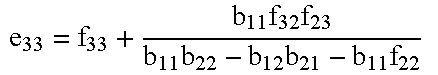
Based on the calculation for the corrected systematic error terms shown in Table 2 above, forward directivity (e00), forward reflection tracking (e10e01), forward source match (e11), reverse load match (e′11), forward transmission tracking (e10e32), reverse directivity (e33), reverse reflection tracking (e23e32), forward load match (e22), reverse source match (e′22), and reverse transmission tracking (e23e01), are calculated as set out by the equations in Table 3 below:
TABLE 3
Forward directivity:
e 00 = f 00 + a 11 f 10 f 01 a 11 a 22 - a 12 a 21 - a 11 f 11
Figure US06188968-20010213-M00010
Forward reflection tracking:
e 10 e 01 = a 21 a 12 f 10 f 01 ( a 11 a 22 - a 12 a 21 - a 11 f 11 ) 2
Figure US06188968-20010213-M00011
Forward source match:
e 11 = a 22 - f 11 a 11 a 22 - a 12 a 21 - a 11 f 11
Figure US06188968-20010213-M00012
Forward load match:
e 22 = b 22 - f 22 b 11 b 22 - b 12 b 21 - a 22 f 22
Figure US06188968-20010213-M00013
Forward transmission tracking:
e 10 e 32 = a 12 b 21 f 10 f 32 ( a 11 a 22 - a 12 a 21 - a 11 f 11 ) ( b 11 b 22 - b 12 b 21 - a 22 f 22 )
Figure US06188968-20010213-M00014
Reverse directivity:
e 33 = f 33 + b 11 f 32 f 23 b 11 b 22 - b 12 b 21 - b 11 f 22
Figure US06188968-20010213-M00015
Reverse reflection tracking:
e 23 e 32 = b 12 b 21 b 23 f 32 ( b 11 b 22 - b 12 b 21 - a 22 f 22 ) 2
Figure US06188968-20010213-M00016
Reverse load match:
e 11 = a 22 - f 11 a 11 a 22 - a 12 a 21 - a 11 f 11
Figure US06188968-20010213-M00017
Reverse source match:
e 22 = b 22 - f 22 b 11 b 22 - b 12 b 21 - a 22 f 22
Figure US06188968-20010213-M00018
Reverse transmission tracking:
e 23 e 01 = a 21 b 12 f 01 f 23 ( b 11 b 22 - b 12 b 21 - a 22 f 22 ) ( a 11 a 22 - a 12 a 21 - a 11 f 11 )
Figure US06188968-20010213-M00019
In the above steps the adapters are assumed to be ideal, so the cross talk terms (e30, e03) are not changed.
The foregoing discussion discloses and describes merely exemplary methods and embodiments of the present invention. As will be understood by those familiar with the art, the invention may be embodied in other specific forms without departing from the spirit or essential characteristics thereof. Accordingly, the disclosure of the present invention is intended to be illustrative, but not limiting, of the scope of the invention, which is set forth in the following claims.

Claims (14)

I claim:
1. A method for removing effects of adapters present during calibration of a network analyzer, comprising the following steps:
(a) obtaining scattering parameters for the adapters;
(b) using the scattering parameters for the adapters to pre-load adapter error terms into the network analyzer before the calibration; and,
(c) performing the calibration with the adapter error terms, pre-loaded in step (b), in order to generate systematic error terms which are exclusive of the effects of the adapters.
2. A method as in claim 1 wherein in step (a) the scattering parameters for the adapters are obtained by characterizing the adapters to generate the scattering parameters.
3. A method as in claim 1 wherein in step (b) the scattering parameters (a11, a12, a21, a22, b11, b12, b21 and b22) are pre-loaded as the adapter error terms (e00, e10e01, e11, e22, e10e32, e33, e23e32, e′11, e′22, e23e01) as set out below:
forward directivity e00 = a11; forward reflection tracking e10e01 = a21a12; forward source match e11 = a22; forward load match e22 = b22; forward transmission tracking e10e32 = a21b12; reverse directivity e33 = b11; reverse reflection tracking e23e32 = b21b12; reverse load match e′11 = a22; reverse source match e′22 = b22; and, reverse transmission tracking e23e01 = b21a12.
4. A method for removing effects of adapters present during calibration of a network analyzer, comprising the following steps:
(a) obtaining scattering parameters for the adapters;
(b) performing the calibration in order to generate preliminary systematic error terms for the calibration; and,
(c) using the preliminary systematic error terms generated in step (b) and the scattering parameters for the adapter obtained in step (a) in order to generate corrected systematic error terms which do not include effects of the adapters.
5. A method as in claim 4 wherein in step (a) the scattering parameters for the adapters are obtained by characterizing the adapters to generate the scattering parameters.
6. A method as in claim 4 wherein in step (c) the corrected systematic error terms (e00, e10e01, e11, e22, e10e32, e33, e23e32, e′11, e′22, e23e01) are generated using the scattering parameters (a11, a12, a21, a22, b11, b12, b21 and b22) and the preliminary systematic error terms (f00, f10e01, f11, f22, f10f32, f33, f23f32, f11, f22, f23f01) as set out below: forward   directivity:                                                                                         e 00 = f 00 + a 11 f 10 f 01 a 11 a 22 - a 12 a 21 - a 11 f 11 ; forward   reflection   tracking:                                                                         e 10 e 01 = a 21 a 12 f 10 f 01 ( a 11 a 22 - a 12 a 21 - a 11 f 11 ) 2 ; forward   source   match:                                                                                  e 11 = a 22 - f 11 a 11 a 22 - a 12 a 21 - a 11 f 11 ; forward   load   match:                                                                                     e 22 = b 22 - f 22 b 11 b 22 - b 12 b 21 - a 22 f 22 ; forward   transmission   tracking:                                                                    e 10 e 32 = a 12 b 21 f 10 f 32 ( a 11 a 22 - a 12 a 21 - a 11 f 11 ) ( b 11 b 22 - b 12 b 21 - a 22 f 22 ) ; reverse   directivity:                                                                                        e 33 = f 33 + b 11 f 32 f 23 b 11 b 22 - b 12 b 21 - b 11 f 22 ; reverse   reflection   tracking:                                                                         e 23 e 32 = b 12 b 21 f 23 f 32 ( b 11 b 22 - b 12 b 21 - a 22 f 22 ) 2 ; reverse   load   match:                                                                                     e 11 = a 22 - f 11 a 11 a 22 - a 12 a 21 - a 11 f 11 ; reverse   source   match:                                                                                  e 22 = b 22 - f 22 b 11 b 22 - b 12 b 21 - a 22 f 22 ; and , reverse   transmission   tracking:                                                                    e 23 e 01 = a 21 b 12 f 01 f 23 ( b 11 b 22 - b 12 b 21 - a 22 f 22 ) ( a 11 a 22 - a 12 a 21 - a 11 f 11 ) .
Figure US06188968-20010213-M00020
7. A method for removing effects of adapters present during calibration of a network analyzer, comprising the following steps:
(a) obtaining scattering parameters for the adapters; and,
(b) using the scattering parameters for the adapters to generate systematic error terms for the calibration which do not take into account effects of the adapters.
8. A method as in claim 7 wherein step (b) comprises the following substeps:
(b.1) using the scattering parameters for the adapters to pre-load adapter error terms into the network analyzer before the calibration; and,
(b.2) performing the calibration with the adapter error terms pre-loaded in substep (b.1), in order to generate the systematic error terms for the calibration.
9. A method as in claim 8 wherein in step (a) the scattering parameters for the adapters are obtained by characterizing the adapters to generate the scattering parameters.
10. A method as in claim 8 wherein in substep (b.1) the scattering parameters (a11, a12, a21, a22, b11, b12, b21 and b22) are pre-loaded as the adapter error terms (e00, e10e01, e11, e22, e10e32, e33, e23e32, e′11, e′22, e23e01) as set out below:
forward directivity e00 = a11; forward reflection tracking e10e01 = a21a12; forward source match e11 = a22; forward load match e22 = b22; forward transmission tracking e10e32 = a21b12; reverse directivity e33 = b11; reverse reflection tracking e23e32 = b21b12; reverse load match e′11 = a22; reverse source match e′22 = b22; and, reverse transmission tracking e23e01 = b21a12.
11. A method as in claim 7 wherein step (b) comprises the following substeps:
(b.1) performing the calibration in order to generate preliminary systematic error terms for the calibration; and,
(b.2) using the preliminary systematic error terms generated in step (b.1) and the scattering parameters for the adapter obtained in step (a) in order to generate the systematic error terms which do not include effects of the adapters.
12. A method as in claim 11 wherein in step (a) the scattering parameters for the adapters are obtained by characterizing the adapters to generate the scattering parameters.
13. A method as in claim 11 wherein in substep (b.2) the systematic error terms (e00, e10e01, e11, e22, e10e32, e33, e23e32, e′11, e′22, e23e01) are generated using the scattering parameters (a11, a12, a21, a22, b11, b12, b21 and b22) and the preliminary systematic error terms (f00, f10e01, f11, f22, f10f32, f33, f23f32, f11, f22, f23f01) as set out below: forward   directivity:                                                                                         e 00 = f 00 + a 11 f 10 f 01 a 11 a 22 - a 12 a 21 - a 11 f 11 ; forward   reflection   tracking:                                                                         e 10 e 01 = a 21 a 12 f 10 f 01 ( a 11 a 22 - a 12 a 21 - a 11 f 11 ) 2 ; forward   source   match:                                                                                  e 11 = a 22 - f 11 a 11 a 22 - a 12 a 21 - a 11 f 11 ; forward   load   match:                                                                                     e 22 = b 22 - f 22 b 11 b 22 - b 12 b 21 - a 22 f 22 ; forward   transmission   tracking:                                                                    e 10 e 32 = a 12 b 21 f 10 f 32 ( a 11 a 22 - a 12 a 21 - a 11 f 11 ) ( b 11 b 22 - b 12 b 21 - a 22 f 22 ) ; reverse   directivity:                                                                                        e 33 = f 33 + b 11 f 32 f 23 b 11 b 22 - b 12 b 21 - b 11 f 22 ; reverse   reflection   tracking:                                                                         e 23 e 32 = b 12 b 21 f 23 f 32 ( b 11 b 22 - b 12 b 21 - a 22 f 22 ) 2 ; reverse   load   match:                                                                                     e 11 = a 22 - f 11 a 11 a 22 - a 12 a 21 - a 11 f 11 ; reverse   source   match:                                                                                  e 22 = b 22 - f 22 b 11 b 22 - b 12 b 21 - a 22 f 22 ; and , reverse   transmission   tracking:                                                                    e 23 e 01 = a 21 b 12 f 01 f 23 ( b 11 b 22 - b 12 b 21 - a 22 f 22 ) ( a 11 a 22 - a 12 a 21 - a 11 f 11 ) .
Figure US06188968-20010213-M00021
14. A method as in claim 7 wherein in step (a) the scattering parameters for the adapters are obtained by characterizing the adapters to generate the scattering parameters.
US09/080,535 1998-05-18 1998-05-18 Removing effects of adapters present during vector network analyzer calibration Expired - Fee Related US6188968B1 (en)

Priority Applications (4)

Application Number Priority Date Filing Date Title
US09/080,535 US6188968B1 (en) 1998-05-18 1998-05-18 Removing effects of adapters present during vector network analyzer calibration
DE19902344A DE19902344A1 (en) 1998-05-18 1999-01-21 Network analyzer calibration method
GB9910407A GB2337604B (en) 1998-05-18 1999-05-05 Network analyzer calibration
JP11136794A JPH11352163A (en) 1998-05-18 1999-05-18 Calibration method of network analyzer

Applications Claiming Priority (1)

Application Number Priority Date Filing Date Title
US09/080,535 US6188968B1 (en) 1998-05-18 1998-05-18 Removing effects of adapters present during vector network analyzer calibration

Publications (1)

Publication Number Publication Date
US6188968B1 true US6188968B1 (en) 2001-02-13

Family

ID=22158016

Family Applications (1)

Application Number Title Priority Date Filing Date
US09/080,535 Expired - Fee Related US6188968B1 (en) 1998-05-18 1998-05-18 Removing effects of adapters present during vector network analyzer calibration

Country Status (4)

Country Link
US (1) US6188968B1 (en)
JP (1) JPH11352163A (en)
DE (1) DE19902344A1 (en)
GB (1) GB2337604B (en)

Cited By (34)

* Cited by examiner, † Cited by third party
Publication number Priority date Publication date Assignee Title
US6496785B1 (en) * 1999-11-25 2002-12-17 Advantest Corporation Network analyzer, network analytical method and recording medium
US6571187B1 (en) * 2000-02-09 2003-05-27 Avaya Technology Corp. Method for calibrating two port high frequency measurements
US6650123B2 (en) 2002-01-15 2003-11-18 Anritsu Company Methods for determining characteristics of interface devices used with vector network analyzers
US6665628B2 (en) 2002-01-15 2003-12-16 Anritsu Company Methods for embedding and de-embedding balanced networks
US20040064774A1 (en) * 2001-02-10 2004-04-01 Hans-Joachim Fabry Method for correcting errors by de-embedding dispersion parameters network analyst and switching module
US20040095145A1 (en) * 2002-11-14 2004-05-20 Ali Boudiaf Method and apparatus for performing multiport through-reflect-line calibration and measurement
US20040100276A1 (en) * 2002-11-25 2004-05-27 Myron Fanton Method and apparatus for calibration of a vector network analyzer
US20040153265A1 (en) * 2003-01-30 2004-08-05 Anritsu Company Flexible vector network analyzer measurements and calibrations
US20040174172A1 (en) * 2003-03-05 2004-09-09 Gaku Kamitani Method of correcting measurement error and electronic component characteristic measurement apparatus
US6791317B1 (en) 2002-12-02 2004-09-14 Cisco Technology, Inc. Load board for testing of RF chips
US20050256658A1 (en) * 2004-05-12 2005-11-17 Anderson Keith F Multi-port scattering parameter calibration system and method
US20050264301A1 (en) * 2004-05-27 2005-12-01 Scott Jonathan B Scattering parameter travelling-wave magnitude calibration system and method
GB2418027A (en) * 2004-09-13 2006-03-15 Agilent Technologies Inc Network analyser with loss compensation
US7030625B1 (en) 2005-01-18 2006-04-18 Agilent Technologies, Inc. Method and apparatus for performing a minimum connection multiport through-reflect-line calibration and measurement
US20060206046A1 (en) * 1994-11-03 2006-09-14 The Saunders Group, Inc. Portable cervical traction device
DE10338072B4 (en) * 2002-09-16 2007-02-08 Agilent Technologies, Inc. (n.d.Ges.d.Staates Delaware), Palo Alto A method and apparatus for calibrating a gauge path and measuring the S-parameters of a test fixture in the calibrated gauge path
US20070073499A1 (en) * 2005-09-27 2007-03-29 Sawyer T S Method and apparatus for determining one or more s-parameters associated with a device under test (DUT)
US20070143051A1 (en) * 2004-02-23 2007-06-21 Advantest Corporation Network analyzer, network analyzing method, program, and recording medium
US20080010034A1 (en) * 2006-07-05 2008-01-10 Takashi Yamasaki Method for network analyzer calibration and network analyzer
US7359814B1 (en) 2000-02-07 2008-04-15 Advantest Multi-port analysis apparatus and method and calibration method thereof
CN100410951C (en) * 2004-03-25 2008-08-13 富士通株式会社 Apparatus and method for s-parameter calculation, and program and recording medium thereof
US20080234992A1 (en) * 2007-03-20 2008-09-25 Pinaki Ray Systems and methods for pattern recognition in diabetes management
US20080258738A1 (en) * 2007-04-20 2008-10-23 Anritsu Company Characterizing test fixtures
US20090030633A1 (en) * 2007-07-23 2009-01-29 Advantest Corporation Device, Method, Program, and Recording Medium for Error Factor Measurement, and Output Measurement Device and Input Measurement Device Provided with the Device for Error Factor Measurement
US20090031172A1 (en) * 2007-07-23 2009-01-29 Advantest Corporation Device, method, program, and recording medium for error factor measurement, and output correction device and reflection coefficient measurement device provided with the device for error factor measurement
US20090184721A1 (en) * 2008-01-17 2009-07-23 Albert-Lebrun Xavier M H Method and system for tracking scattering parameter test system calibration
US20110140006A1 (en) * 1997-07-22 2011-06-16 Satoshi Tomimatsu Method and apparatus for specimen fabrication
CN102841261A (en) * 2011-06-22 2012-12-26 纬创资通股份有限公司 Method for measuring scattering parameter of object to be measured
CN102981135A (en) * 2012-11-13 2013-03-20 哈尔滨工业大学 Twin port calibration method for nonlinearity vector network analyzer
CN103399286A (en) * 2013-07-16 2013-11-20 中国电子科技集团公司第四十一研究所 Measurement calibration method for multi-characteristic impedance network
CN104375011A (en) * 2014-11-04 2015-02-25 中国电子科技集团公司第四十一研究所 Random impedance testing circuit and method for vector network analyzer material testing
CN109239634A (en) * 2018-09-10 2019-01-18 中国科学院电子学研究所 The method of Two-port netwerk vector network analyzer calibration based on ridge regression
US10473703B2 (en) 2013-12-20 2019-11-12 Advantest Corporation Multi-port measurement technique
WO2024060040A1 (en) * 2022-09-20 2024-03-28 京东方科技集团股份有限公司 Single-channel test device and system, and test method

Families Citing this family (6)

* Cited by examiner, † Cited by third party
Publication number Priority date Publication date Assignee Title
WO2003087856A1 (en) * 2002-04-17 2003-10-23 Advantest Corporation Network analyzer, network analyzing method, automatic corrector, correcting method, program, and recording medium
WO2004055527A1 (en) * 2002-12-12 2004-07-01 Ideal Industries, Inc. Patchcord length measurement for a lan testers
KR101139953B1 (en) 2010-09-09 2012-04-30 주식회사 이노와이어리스 switching apparatus for RF performance test
US9581675B2 (en) * 2012-08-24 2017-02-28 Tektronix, Inc. Virtual model adapter removal and substitution technique for cascaded networks
WO2016163932A1 (en) * 2015-04-08 2016-10-13 Gapwaves Ab A calibration arrangement and a method for a microwave analyzing or measuring instrument
WO2019188549A1 (en) * 2018-03-30 2019-10-03 日本電産リード株式会社 Connection jig

Citations (6)

* Cited by examiner, † Cited by third party
Publication number Priority date Publication date Assignee Title
US5175492A (en) * 1989-08-08 1992-12-29 Hewlett-Packard Company Calibration and error correction for electrical-source-to-e/o-device impedance mismatch and o/e-device-to-electrical-receiver impedance mismatch in a lightwave component analyzer
US5311440A (en) * 1991-12-03 1994-05-10 Scientific-Atlanta, Inc. Methods and apparatus for correction of cable variations
US5552714A (en) * 1993-05-24 1996-09-03 Atn Microwave, Inc. Electronic calibration method and apparatus
US5666059A (en) * 1994-10-05 1997-09-09 Rohde & Schwarz Gmbh & Co. Kg Method for calibrating a network analyzer according to the fifteen-term principle
US6060888A (en) * 1998-04-24 2000-05-09 Hewlett-Packard Company Error correction method for reflection measurements of reciprocal devices in vector network analyzers
US6081125A (en) * 1993-08-30 2000-06-27 Rohde & Schwarz Gmbh & Co. Kg Network analyzer

Family Cites Families (1)

* Cited by examiner, † Cited by third party
Publication number Priority date Publication date Assignee Title
DE3821575A1 (en) * 1988-06-25 1989-12-28 Philips Patentverwaltung ARRANGEMENT FOR APPROXIMATELY DETERMINING THE REPLACEMENT CIRCUIT OF AN ELECTRICAL OR. ELECTRONIC COMPONENTS AT HIGH FREQUENCIES

Patent Citations (7)

* Cited by examiner, † Cited by third party
Publication number Priority date Publication date Assignee Title
US5175492A (en) * 1989-08-08 1992-12-29 Hewlett-Packard Company Calibration and error correction for electrical-source-to-e/o-device impedance mismatch and o/e-device-to-electrical-receiver impedance mismatch in a lightwave component analyzer
US5311440A (en) * 1991-12-03 1994-05-10 Scientific-Atlanta, Inc. Methods and apparatus for correction of cable variations
US5552714A (en) * 1993-05-24 1996-09-03 Atn Microwave, Inc. Electronic calibration method and apparatus
US5578932A (en) * 1993-05-24 1996-11-26 Atn Microwave, Inc. Method and apparatus for providing and calibrating a multiport network analyzer
US6081125A (en) * 1993-08-30 2000-06-27 Rohde & Schwarz Gmbh & Co. Kg Network analyzer
US5666059A (en) * 1994-10-05 1997-09-09 Rohde & Schwarz Gmbh & Co. Kg Method for calibrating a network analyzer according to the fifteen-term principle
US6060888A (en) * 1998-04-24 2000-05-09 Hewlett-Packard Company Error correction method for reflection measurements of reciprocal devices in vector network analyzers

Non-Patent Citations (4)

* Cited by examiner, † Cited by third party
Title
Dhaene et al., "Calibration and Normalization of Time Domain Network Analyzer Measurments", IEEE, 1994. *
Dibeneditto et al., "Adapter Correction in the Measurement of Two-Port Devices", IEEE, 1988. *
Doug Rytting, Advances in Microwave Error Correction Techniques, RF & Microwave Measurement Symposium and Exhibition, Hewlett-Packard Company, 1987.
Randa et al., "Comparison of Adapter Characterization Methods", IEEE, 1999. *

Cited By (54)

* Cited by examiner, † Cited by third party
Publication number Priority date Publication date Assignee Title
US20060206046A1 (en) * 1994-11-03 2006-09-14 The Saunders Group, Inc. Portable cervical traction device
US8405053B2 (en) 1997-07-22 2013-03-26 Hitachi, Ltd. Method and apparatus for specimen fabrication
US20110140006A1 (en) * 1997-07-22 2011-06-16 Satoshi Tomimatsu Method and apparatus for specimen fabrication
US6496785B1 (en) * 1999-11-25 2002-12-17 Advantest Corporation Network analyzer, network analytical method and recording medium
US7359814B1 (en) 2000-02-07 2008-04-15 Advantest Multi-port analysis apparatus and method and calibration method thereof
US6571187B1 (en) * 2000-02-09 2003-05-27 Avaya Technology Corp. Method for calibrating two port high frequency measurements
US20040064774A1 (en) * 2001-02-10 2004-04-01 Hans-Joachim Fabry Method for correcting errors by de-embedding dispersion parameters network analyst and switching module
US7075312B2 (en) * 2001-02-10 2006-07-11 Rohde & Schwarz Gmbh & Co. Kg Method for correcting errors by de-embedding dispersion parameters network analyst and switching module
US6650123B2 (en) 2002-01-15 2003-11-18 Anritsu Company Methods for determining characteristics of interface devices used with vector network analyzers
US6665628B2 (en) 2002-01-15 2003-12-16 Anritsu Company Methods for embedding and de-embedding balanced networks
DE10338072B4 (en) * 2002-09-16 2007-02-08 Agilent Technologies, Inc. (n.d.Ges.d.Staates Delaware), Palo Alto A method and apparatus for calibrating a gauge path and measuring the S-parameters of a test fixture in the calibrated gauge path
US20040095145A1 (en) * 2002-11-14 2004-05-20 Ali Boudiaf Method and apparatus for performing multiport through-reflect-line calibration and measurement
US6853198B2 (en) * 2002-11-14 2005-02-08 Agilent Technologies, Inc. Method and apparatus for performing multiport through-reflect-line calibration and measurement
US20040100276A1 (en) * 2002-11-25 2004-05-27 Myron Fanton Method and apparatus for calibration of a vector network analyzer
US6791317B1 (en) 2002-12-02 2004-09-14 Cisco Technology, Inc. Load board for testing of RF chips
US6928373B2 (en) 2003-01-30 2005-08-09 Anritsu Company Flexible vector network analyzer measurements and calibrations
US20040153265A1 (en) * 2003-01-30 2004-08-05 Anritsu Company Flexible vector network analyzer measurements and calibrations
US6960920B2 (en) * 2003-03-05 2005-11-01 Murata Manufacturing Co., Ltd. Method for correcting measurement error and electronic component characteristic measurement apparatus
US6838885B2 (en) * 2003-03-05 2005-01-04 Murata Manufacturing Co., Ltd. Method of correcting measurement error and electronic component characteristic measurement apparatus
US20040183542A1 (en) * 2003-03-05 2004-09-23 Murata Manufacturing Co., Ltd. Method for correcting measurement error and electronic component characteristic measurement apparatus
US20040174172A1 (en) * 2003-03-05 2004-09-09 Gaku Kamitani Method of correcting measurement error and electronic component characteristic measurement apparatus
US20070143051A1 (en) * 2004-02-23 2007-06-21 Advantest Corporation Network analyzer, network analyzing method, program, and recording medium
US20090276177A1 (en) * 2004-02-23 2009-11-05 Rohde & Schwarz Gmbh & Co. Kg Network analyzer, network analyzing method, program, and recording medium
US7561987B2 (en) 2004-02-23 2009-07-14 Rohde & Schwarz Gmbh & Co. Kg Network analyzer, network analyzing method, program, and recording medium
US7996184B2 (en) 2004-02-23 2011-08-09 Rohde & Schwarz Gmbh & Co., Kg Network analyzer, network analyzing method, program, and recording medium
CN100410951C (en) * 2004-03-25 2008-08-13 富士通株式会社 Apparatus and method for s-parameter calculation, and program and recording medium thereof
US20050256658A1 (en) * 2004-05-12 2005-11-17 Anderson Keith F Multi-port scattering parameter calibration system and method
US7113891B2 (en) * 2004-05-12 2006-09-26 Agilent Technologies, Inc. Multi-port scattering parameter calibration system and method
US6982561B2 (en) 2004-05-27 2006-01-03 Agilent Technologies, Inc. Scattering parameter travelling-wave magnitude calibration system and method
US20050264301A1 (en) * 2004-05-27 2005-12-01 Scott Jonathan B Scattering parameter travelling-wave magnitude calibration system and method
GB2418027A (en) * 2004-09-13 2006-03-15 Agilent Technologies Inc Network analyser with loss compensation
US7030625B1 (en) 2005-01-18 2006-04-18 Agilent Technologies, Inc. Method and apparatus for performing a minimum connection multiport through-reflect-line calibration and measurement
US20070073499A1 (en) * 2005-09-27 2007-03-29 Sawyer T S Method and apparatus for determining one or more s-parameters associated with a device under test (DUT)
US20080010034A1 (en) * 2006-07-05 2008-01-10 Takashi Yamasaki Method for network analyzer calibration and network analyzer
US20080234992A1 (en) * 2007-03-20 2008-09-25 Pinaki Ray Systems and methods for pattern recognition in diabetes management
US20080258738A1 (en) * 2007-04-20 2008-10-23 Anritsu Company Characterizing test fixtures
US7545151B2 (en) 2007-04-20 2009-06-09 Anritsu Company Characterizing test fixtures
US7761253B2 (en) 2007-07-23 2010-07-20 Advantest Corporation Device, method, program, and recording medium for error factor measurement, and output measurement device and input measurement device provided with the device for error factor measurement
US20090031172A1 (en) * 2007-07-23 2009-01-29 Advantest Corporation Device, method, program, and recording medium for error factor measurement, and output correction device and reflection coefficient measurement device provided with the device for error factor measurement
US20090030633A1 (en) * 2007-07-23 2009-01-29 Advantest Corporation Device, Method, Program, and Recording Medium for Error Factor Measurement, and Output Measurement Device and Input Measurement Device Provided with the Device for Error Factor Measurement
US7616007B2 (en) 2007-07-23 2009-11-10 Advantest Corporation Device, method, program, and recording medium for error factor measurement, and output correction device and reflection coefficient measurement device provided with the device for error factor measurement
US7777497B2 (en) 2008-01-17 2010-08-17 Com Dev International Ltd. Method and system for tracking scattering parameter test system calibration
US20090184721A1 (en) * 2008-01-17 2009-07-23 Albert-Lebrun Xavier M H Method and system for tracking scattering parameter test system calibration
CN102841261A (en) * 2011-06-22 2012-12-26 纬创资通股份有限公司 Method for measuring scattering parameter of object to be measured
US20120326737A1 (en) * 2011-06-22 2012-12-27 Wistron Corp. Method of measuring scattering parameters of device under test
US8860434B2 (en) * 2011-06-22 2014-10-14 Wistron Corp. Method of measuring scattering parameters of device under test
CN102981135B (en) * 2012-11-13 2014-12-10 哈尔滨工业大学 Twin port calibration method for nonlinearity vector network analyzer
CN102981135A (en) * 2012-11-13 2013-03-20 哈尔滨工业大学 Twin port calibration method for nonlinearity vector network analyzer
CN103399286A (en) * 2013-07-16 2013-11-20 中国电子科技集团公司第四十一研究所 Measurement calibration method for multi-characteristic impedance network
US10473703B2 (en) 2013-12-20 2019-11-12 Advantest Corporation Multi-port measurement technique
CN104375011A (en) * 2014-11-04 2015-02-25 中国电子科技集团公司第四十一研究所 Random impedance testing circuit and method for vector network analyzer material testing
CN104375011B (en) * 2014-11-04 2017-03-08 中国电子科技集团公司第四十一研究所 A kind of any resistance test circuit for vector network analyzer testing of materials and method
CN109239634A (en) * 2018-09-10 2019-01-18 中国科学院电子学研究所 The method of Two-port netwerk vector network analyzer calibration based on ridge regression
WO2024060040A1 (en) * 2022-09-20 2024-03-28 京东方科技集团股份有限公司 Single-channel test device and system, and test method

Also Published As

Publication number Publication date
GB2337604B (en) 2002-12-11
GB9910407D0 (en) 1999-07-07
GB2337604A (en) 1999-11-24
JPH11352163A (en) 1999-12-24
DE19902344A1 (en) 1999-12-09

Similar Documents

Publication Publication Date Title
US6188968B1 (en) Removing effects of adapters present during vector network analyzer calibration
US6417674B1 (en) Two port self-calibration for an N-port network analyzer
US8860434B2 (en) Method of measuring scattering parameters of device under test
US7034548B2 (en) Balanced device characterization including test system calibration
US6060888A (en) Error correction method for reflection measurements of reciprocal devices in vector network analyzers
US7061254B1 (en) Power calibration for multi-port vector network analyzer (VNA)
US6853198B2 (en) Method and apparatus for performing multiport through-reflect-line calibration and measurement
US6421624B1 (en) Multi-port device analysis apparatus and method and calibration method thereof
US7068049B2 (en) Method and apparatus for measuring a device under test using an improved through-reflect-line measurement calibration
US7256585B1 (en) Match-corrected power measurements with a vector network analyzer
US6268735B1 (en) Noise source module for microwave test systems
US6836743B1 (en) Compensating for unequal load and source match in vector network analyzer calibration
US4853613A (en) Calibration method for apparatus evaluating microwave/millimeter wave circuits
US6397160B1 (en) Power sensor module for microwave test systems
US11927661B2 (en) Integrated vector network analyzer
US20040251922A1 (en) Methods and computer program products for full N-port vector network analyzer calibrations
US10969421B2 (en) Integrated vector network analyzer
US7030625B1 (en) Method and apparatus for performing a minimum connection multiport through-reflect-line calibration and measurement
JPH11118853A (en) Automatic calibration of network analyzer
US7002335B2 (en) Method for measuring a three-port device using a two-port vector network analyzer
US5734268A (en) Calibration and measurment technique and apparatus for same
US6965241B1 (en) Automated electronic calibration apparatus
US7359814B1 (en) Multi-port analysis apparatus and method and calibration method thereof
Ferrero et al. A simplified algorithm for leaky network analyzer calibration
US6571187B1 (en) Method for calibrating two port high frequency measurements

Legal Events

Date Code Title Description
AS Assignment

Owner name: HEWLETT-PACKARD COMPANY, CALIFORNIA

Free format text: ASSIGNMENT OF ASSIGNORS INTEREST;ASSIGNOR:BLACKHAM, DAVID VERNON;REEL/FRAME:009338/0481

Effective date: 19980514

AS Assignment

Owner name: HEWLETT-PACKARD COMPANY, COLORADO

Free format text: MERGER;ASSIGNOR:HEWLETT-PACKARD COMPANY;REEL/FRAME:010759/0049

Effective date: 19980520

AS Assignment

Owner name: AGILENT TECHNOLOGIES INC, CALIFORNIA

Free format text: ASSIGNMENT OF ASSIGNORS INTEREST;ASSIGNOR:HEWLETT-PACKARD COMPANY;REEL/FRAME:010977/0540

Effective date: 19991101

FEPP Fee payment procedure

Free format text: PAYOR NUMBER ASSIGNED (ORIGINAL EVENT CODE: ASPN); ENTITY STATUS OF PATENT OWNER: LARGE ENTITY

FPAY Fee payment

Year of fee payment: 4

FPAY Fee payment

Year of fee payment: 8

REMI Maintenance fee reminder mailed
LAPS Lapse for failure to pay maintenance fees
STCH Information on status: patent discontinuation

Free format text: PATENT EXPIRED DUE TO NONPAYMENT OF MAINTENANCE FEES UNDER 37 CFR 1.362

FP Lapsed due to failure to pay maintenance fee

Effective date: 20130213