US6189446B1 - System for the secure destruction of compact disc data - Google Patents
System for the secure destruction of compact disc data Download PDFInfo
- Publication number
- US6189446B1 US6189446B1 US09/303,325 US30332599A US6189446B1 US 6189446 B1 US6189446 B1 US 6189446B1 US 30332599 A US30332599 A US 30332599A US 6189446 B1 US6189446 B1 US 6189446B1
- Authority
- US
- United States
- Prior art keywords
- rollers
- media
- applying pressure
- data
- disc
- Prior art date
- Legal status (The legal status is an assumption and is not a legal conclusion. Google has not performed a legal analysis and makes no representation as to the accuracy of the status listed.)
- Expired - Lifetime
Links
- 230000006378 damage Effects 0.000 title description 29
- 238000004049 embossing Methods 0.000 claims abstract description 15
- 238000009877 rendering Methods 0.000 claims abstract description 6
- 238000000034 method Methods 0.000 claims abstract description 5
- 238000003825 pressing Methods 0.000 claims description 11
- 230000000750 progressive effect Effects 0.000 claims 1
- 230000000717 retained effect Effects 0.000 claims 1
- 229910052751 metal Inorganic materials 0.000 description 9
- 239000002184 metal Substances 0.000 description 9
- 239000000758 substrate Substances 0.000 description 8
- 229910052782 aluminium Inorganic materials 0.000 description 6
- XAGFODPZIPBFFR-UHFFFAOYSA-N aluminium Chemical compound [Al] XAGFODPZIPBFFR-UHFFFAOYSA-N 0.000 description 6
- 229920000515 polycarbonate Polymers 0.000 description 6
- 239000004417 polycarbonate Substances 0.000 description 6
- 238000013459 approach Methods 0.000 description 5
- 239000003082 abrasive agent Substances 0.000 description 4
- 239000003517 fume Substances 0.000 description 4
- PCHJSUWPFVWCPO-UHFFFAOYSA-N gold Chemical compound [Au] PCHJSUWPFVWCPO-UHFFFAOYSA-N 0.000 description 4
- 229910052737 gold Inorganic materials 0.000 description 4
- 239000010931 gold Substances 0.000 description 4
- 230000001473 noxious effect Effects 0.000 description 4
- 230000008901 benefit Effects 0.000 description 3
- 230000003287 optical effect Effects 0.000 description 3
- 239000002245 particle Substances 0.000 description 3
- 238000003486 chemical etching Methods 0.000 description 2
- 238000005516 engineering process Methods 0.000 description 2
- 238000004519 manufacturing process Methods 0.000 description 2
- 238000011084 recovery Methods 0.000 description 2
- 230000015572 biosynthetic process Effects 0.000 description 1
- 238000006243 chemical reaction Methods 0.000 description 1
- 238000004140 cleaning Methods 0.000 description 1
- 150000001875 compounds Chemical class 0.000 description 1
- 238000010276 construction Methods 0.000 description 1
- 238000006073 displacement reaction Methods 0.000 description 1
- 238000010438 heat treatment Methods 0.000 description 1
- 238000007373 indentation Methods 0.000 description 1
- 238000002372 labelling Methods 0.000 description 1
- 239000004922 lacquer Substances 0.000 description 1
- 239000000463 material Substances 0.000 description 1
- 238000012986 modification Methods 0.000 description 1
- 230000004048 modification Effects 0.000 description 1
- 230000001681 protective effect Effects 0.000 description 1
- 230000008707 rearrangement Effects 0.000 description 1
- 238000003860 storage Methods 0.000 description 1
- 238000006467 substitution reaction Methods 0.000 description 1
Images


Classifications
-
- G—PHYSICS
- G11—INFORMATION STORAGE
- G11B—INFORMATION STORAGE BASED ON RELATIVE MOVEMENT BETWEEN RECORD CARRIER AND TRANSDUCER
- G11B23/00—Record carriers not specific to the method of recording or reproducing; Accessories, e.g. containers, specially adapted for co-operation with the recording or reproducing apparatus ; Intermediate mediums; Apparatus or processes specially adapted for their manufacture
- G11B23/50—Reconditioning of record carriers; Cleaning of record carriers ; Carrying-off electrostatic charges
- G11B23/505—Reconditioning of record carriers; Cleaning of record carriers ; Carrying-off electrostatic charges of disk carriers
-
- B—PERFORMING OPERATIONS; TRANSPORTING
- B09—DISPOSAL OF SOLID WASTE; RECLAMATION OF CONTAMINATED SOIL
- B09B—DISPOSAL OF SOLID WASTE
- B09B5/00—Operations not covered by a single other subclass or by a single other group in this subclass
-
- B—PERFORMING OPERATIONS; TRANSPORTING
- B44—DECORATIVE ARTS
- B44B—MACHINES, APPARATUS OR TOOLS FOR ARTISTIC WORK, e.g. FOR SCULPTURING, GUILLOCHING, CARVING, BRANDING, INLAYING
- B44B5/00—Machines or apparatus for embossing decorations or marks, e.g. embossing coins
- B44B5/0004—Machines or apparatus for embossing decorations or marks, e.g. embossing coins characterised by the movement of the embossing tool(s), or the movement of the work, during the embossing operation
- B44B5/0009—Rotating embossing tools
Definitions
- This invention is directed generally to the field of data destruction and, more particularly, to a device that destroys the data contained on compact discs.
- Compact discs also known as CD's
- CD's are convenient, durable storage devices that are capable of holding large amounts of data.
- Information on a CD is typically recorded as a series of peaks and valleys located on a reflective metallic layer disposed within the disc itself.
- CD The information stored on a CD is not directly readable by the human eye; a CD player is typically used to access data stored on a given CD. CD players use lasers to “read” CD's, gathering information about the peaks and valleys on the reflective layer of a given disc. This information is processed by an associated computer which then converts the information for use.
- the disc To achieve secure destruction of the information on a compact disc, the disc must be altered so that no technology can be employed to access any of the information previously recorded on the disc.
- the term “secure” destruction of data refers to the destruction of data in a manner that makes the data irretrievable by any means. The irretrievability requirement is of particular importance to government-agencies, especially those agencies involved with issues of national security.
- a device for the secure destruction of CD data must irretrievably destroy the data on the disc without producing noxious fumes and must continue to operate over an extended period of time, having the capacity to destroy the information on more than three CD's.
- the compact disc data destruction device should alter selected compact discs to destroy the data recorded on the disc so that recovery of the data is prevented.
- the device should also destroy the information on a compact disc while leaving the associated disc label in a legible format, so that the disc may be identified and accurately stored or discarded as needed.
- the device should also be clean to use and should not produce noxious fumes.
- the device should also be useable for an extended period of time, enabling destruction of data on many CD's, regardless of the type of material used for the disc information bearing surface.
- the device should also be economical and easy to use.
- the present invention is a system for securely destroying data contained on compact discs (CD's) having gold or aluminum information bearing surfaces (IBS's).
- CD's compact discs
- IBS's gold or aluminum information bearing surfaces
- the system includes at least one pair, and typically two pairs, of rollers with each roller being rotatably mounted between rigid support plates.
- a CD containing information to be destroyed passes between the rollers under pressure.
- the roller exteriors contain raised patterns that are impressed into the surface of the disc as the disc passes between the rollers.
- the disc surface is significantly distorted as the disc passes between the rollers.
- the disc is characterized by lines of distortion that are approximately 0.25 mm apart. This spacing results in a CD from which no useful information can be retrieved. It is noted that the present invention could also be used to destroy data on a variety of recording media, including, but not limited to analog phonograph records, Digital video discs (DVD's), and laser video discs.
- the patterns on the rollers may be varied greatly to avoid embossing predictable patterns on a disc.
- the bottom-facing rollers distort the clear substrate of the disc, making it more difficult to read the data on the metal surface through the substrate.
- the pattern on each set of rollers may be different, thereby embossing cooperative, overlaying patterns. This overlay results in a widespread distortion of the disc surfaces, with distances between embossed lines much smaller than would normally be produced by a single set of rollers.
- the present invention destroys data, yet preserves the original identification information used for record keeping purposes.
- it is an objective of the present invention is to provide a device that securely destroys the data contained on CD's incorporating either aluminum or gold information bearing surfaces.
- An additional objective of the instant invention is to provide a compact disc data destruction device that alters selected compact discs to destroy the data recorded on the disc so that recovery of the data is prevented.
- Yet another objective of the instant invention is to provide a compact disc data destruction device that destroys the information on a compact disc while leaving the associated disc label in a legible format, so that the disc may be identified and accurately stored or discarded as needed.
- a further objective of the instant invention is to provide a compact disc data destruction device that is clean to use and does not produce noxious fumes.
- Still an additional objective of the instant invention is to provide a compact disc data destruction device that is useable for an extended period of time, enabling destruction of data on many CD's, if desired.
- a still further objective of the instant invention is to provide a compact disc data destruction device that is economical and easy to use.
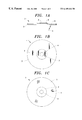
- FIG. 1A is a side elevation view of a compact disc
- FIG. 1B is a top plan view of a compact disc
- FIG. 1C is a bottom plan view of a compact disc
- FIG. 2 is a pictorial view of the compact disc data destruction device of the present invention.
- FIG. 3 is a top plan view of the drive assembly of the present invention and a compact disc passing between the rollers of the present invention
- FIG. 4 is a partial close-up view of a compact disc showing the type of destruction accomplished with the present invention.
- FIG. 5 is a front view elevation of a set of rollers used in the present invention.
- FIGS. 1A, 1 B and 1 C show, respectively, a side sectional view, a top plan view, and a bottom view of a compact disc.
- the CD may alternatively be referred to as a CD-ROM (Compact-Disc-Read-Only Memory) or a CD-WORM (Compact-Disc Write-Once-Read-Many). Many acronyms are used to describe the CD and similar optical recording media.
- the CD 1 comprises several layers, the first of which is a layer of clear polycarbonate 2 .
- the polycarbonate layer 2 forms the basic substrate for the CD 1 .
- the next layer 3 is a thin layer of reflective metal film located on the upper side of the polycarbonate disc 2 .
- This reflective layer 3 is the recording media in the CD 1 .
- Above the metal layer 3 is a label 4 .
- the label 4 often consists of silk-screened ink and a protective lacquer coat and forms the top surface of the CD 1 .
- the label 4 is typically a narrow band near the center of the disc about a central aperture 5 . This aperture 5 is used to position and spin the CD 1 in recording and playback operations.
- the reflective metal layer 3 and the label 4 are generally very thin in comparison with the polycarbonate substrate 2 , but have been shown relatively-large in FIG. 1A, for the sake of clarity.
- FIG. 1C shows a bottom view of a CD in which there appears to be a plurality of rings 7 .
- These “rings” 7 are actually a single, tightly-wound spiraling groove, similar to that found on an audio record disc.
- the single spiraling groove 7 is located on the top surface of the CD substrate 2 , but is visible only from the lower side, through the clear polycarbonate substrate 2 .
- the spiraling groove 7 generally cannot be seen from the top of the CD 1 , because the groove is filled in by the metal layer 3 .
- the CD is placed in a CD player and rotated about the disc central axis; the disc central axis coincides with the center of the disc aperture 5 .
- a laser beam such as beam 6 shown in FIG. 1A, is directed to illuminate precisely-selected portions of the spiral groove 7 .
- the beam 6 is typically directed from under the CD 1 . More particularly, the laser beam 6 passes through the clear polycarbonate substrate 2 of the CD 1 and travels to the reflective metal layer 3 .
- the laser beam 6 Upon striking the reflective metal layer 3 , the laser beam 6 illuminates information-carrying indentations, not shown, located thereupon. In turn, portions of the laser beam 6 are reflected back to an optical sensor, not shown, which produces electrical output that varies in accordance with the reflected laser beam 6 .
- secure data destruction refers to destruction that alters a CD 1 so that no intelligible information can be retrieved from the CD.
- the pits are typically about 0.5 micrometers wide and 0.833 micrometers long.
- the pits are “read” by a 780-nanometer laser diode, the light from which is invisible to the naked eye.
- the present invention 100 distorts a CD 1 sufficiently to prevent a laser 6 from reading information stored within the groove 7 . This is due to a number of physical changes the rollers 10 a , 11 a , 12 a , and 13 a of the present invention 100 impart on a CD 1 that passes therebetween.
- these changes include distortion of the shape of the pits, movement of the pits from their original positions, displacement of the reflective layer 3 at the base of the pits so that the laser beam 6 is no longer reflected back properly to the optical sensor, “filling in” of the pits by the crushing action of the rollers 10 a , 11 a , 12 a , and 13 a , and production of imperfections, on the substrate 2 and reflective surface 3 , that block light 6 from the laser and interfere with laser light reflection.
- these physical changes make retrieval of data carried by the information bearing surface 3 (IBS) of a CD 1 impossible.
- IBS information bearing surface 3
- the destruction of information by this method is effective with a wide variety of IBS's 3 , including those that are aluminum or gold.
- the present invention provides increased utility over the prior art, including abrasive systems limited to the destruction of aluminum IBS's.
- a CD 1 passes between a first roller 12 a and second roller 11 a progressively applying pressure to the CD.
- the CD then continues moving, being forced to pass between a third roller 10 a and a fourth roller 13 a .
- the roller surfaces 20 include a fine pattern that is impressed on the CD 1 as the CD travels between the first pair of rollers 11 a , 12 a and then between the second pair of rollers 10 a , 13 a .
- One preferred pattern 20 is seen in FIG. 5 .
- the reflective information bearing layer 3 is distorted and subsequent retrieval of data on that layer is prevented.
- the fine pattern 20 advantageously does not destroy an identification label 4 printed on the CD 1 .
- the CD 1 may still be identified for archival purposes, even after the data contained on the disc 1 is no longer readable.
- FIG. 2 shows a pictorial view of the present invention 100 .
- the present invention 100 includes a first pair of rollers 10 a , 11 a and a second pair of rollers 12 a , 13 a .
- a first driving gear 10 b is disposed on the first gear 10 a
- a second driving gear 12 b is disposed on the third roller 12 a.
- the driving gears 10 b , 12 b are coplanar and sized so that gear 10 b engages gear 12 b during rotation. With this arrangement, when the first roller 10 a rotates, the first drive gear 10 b engages the second drive gear 12 b , thereby rotating the third roller 12 a . This ensures that the device 100 will force a CD 1 through both sets of rollers 10 a , 11 a and 12 a , 13 a with continued rotation of the drive gears 10 b , 12 b . Other numbers of drive gears may also be used, if desired.
- a CD disc 1 is forced between the first set of rollers 11 a , 12 a and then through the second set of rollers 10 a , 13 a .
- the second pair of rollers 12 a , 13 a is laterally offset from the first pair of rollers 10 a , 11 a.
- the clearance between the first roller 10 a and the second roller 11 a is approximately ten thousandth of an inch.
- the clearance between the third roller 12 a and the fourth roller 13 a is also approximately ten thousandth of an inch.
- a typical CD 1 is approximately fifty thousandths of an inch thick.
- the two pairs of rollers 10 a , 11 a and 12 a , 13 a cooperatively compress a CD 1 passing therebetween.
- the patterns on the roller surfaces 20 become embossed into the top 4 and bottom surfaces 2 of the CD 1 .
- a preferred pattern 20 on the rollers is shown is FIG. 5 to be a diamond-shaped pattern, other patterns would also suffice; rollers having flat surfaces may also be used.
- rollers within a pair 10 a , 11 a and 12 a , 13 a that produces desired destruction of the IBS 3 . If rollers within a pair 10 a , 11 a and 12 a , 13 a are spaced apart too far, the IBS 3 will not be sufficiently disturbed to totally destroy all the information on the disc 1 . However, excessive pressure, due to rollers 10 a , 11 a and 12 a , 13 a that are too close can cause large, information-carrying segments of the IBS 3 to flake off. Although the spacing roller is set at the factory, it may be maintained in the field.
- FIG. 4 shows a partial view of a CD 1 that has passed through the first and second pairs of rollers 10 a , 11 a , and 12 a , 13 a of the present invention 100 .
- the reflective metal layer 3 becomes riddled with distorted areas 3 a , formed by lines of distortion 3 b .
- substantially the entire reflective layer 3 is characterized by areas of distortion 3 a ; the information previously stored on the CD is destroyed.
- the drive gears 10 b , 12 b engage one another.
- driving gear 10 b and attached roller 10 a in a clockwise direction will turn gear 12 b and attached roller 12 a in a counter clockwise direction.
- This cooperative rotation will force a compact disc 1 between, and past, the first set of rollers 10 a , 11 a .
- the CD 1 emerges from between the first set of rollers 10 a , 11 a , the CD will continue moving into the second set of rollers 12 a , 13 a .
- Trunnions 22 extend from each end of the roller 10 a .
- the trunnions 22 rotatably extend through bearing plates 24 , 26 thereby allowing the roller 10 a to turn in a supported manner.
- the bearing plates 24 , 26 may include roller mounting apertures, not shown, having ball bearings, not shown, to reduce friction between the bearing plates 24 , 26 and the roller trunnions 22 .
- a single drive belt 14 links a drive pulley 16 with a motor pulley 15 a .
- the drive pulley 16 is connected to the first roller 10 a . More particularly, the drive pulley 16 is axially aligned with, and adjacent to, the first drive gear 10 a . Rotation of the motor pulley 15 a causes the drive 14 belt to rotate, thereby rotating the first drive gear 10 a and the first roller 10 a . Continued rotation of the drive pulley 14 will produce tandem rotation of the roller pairs 10 a , 11 a and 12 a , 13 a , as a CD is forced therebetween, as described above.
- the drive assembly 28 has been described as including a drive belt 14 , motor pulley 15 a , a drive pulley 16 other arrangements could also be used.
- the belt and pulley arrangement shown in FIG. 3 may replaced by a drive chain 14 ′ and associated gears 15 a ′, 16 ′, as shown in FIG. 2 .
- the drive assembly 28 includes a motor 15 , a motor pulley 15 a mounted on the drive shaft of motor 15 , and a drive pulley 16 .
- a drive belt 14 links the motor pulley 15 a with the drive pulley 16 .
- the motor pulley 15 a , drive pulley 16 , and gear 11 b are also driven in a clockwise direction.
- the present invention has been described in terms of destroying in formation on compact discs, the present invention is not only useful for rendering data on compact discs unintelligible.
- the present invention could also be used to render unintelligible data on a variety of recording media, including, but not limited to analog phonograph records, digital video discs (DVD's), and laser video discs.
Abstract
An apparatus and process for the rendering unintelligible of data stored on digital and analog recording media employs a means for embossing the media and a means for driving the media to traverse a path defined by the means for embossing. In one embodiment, the means for embossing includes knurled rollers that distort the surfaces of recording media passed therebetween. In one embodiment, the means for driving the recording media through the means for embossing includes a motor and at least one drive gear operatively associated with the means for embossing. The process for rendering recorded data unintelligible includes the steps of providing a means for embossing, providing a means for driving recording media through the means for embossing, and urging recording media through the means for embossing.
Description
This non-provisional application, which is based upon provisional application Ser. No. 60/115,078, filed on Jan. 7, 1999, claims benefit of the filing date thereof in accordance with 35 USC 119(e). The contents of said provisional application Ser. No. 60/115,078 are herein incorporated by reference.
This invention is directed generally to the field of data destruction and, more particularly, to a device that destroys the data contained on compact discs.
Compact discs, also known as CD's, are convenient, durable storage devices that are capable of holding large amounts of data. Information on a CD is typically recorded as a series of peaks and valleys located on a reflective metallic layer disposed within the disc itself.
The information stored on a CD is not directly readable by the human eye; a CD player is typically used to access data stored on a given CD. CD players use lasers to “read” CD's, gathering information about the peaks and valleys on the reflective layer of a given disc. This information is processed by an associated computer which then converts the information for use.
Since the data stored on a compact disc is not accessible directly and must be converted before use, it is possible to prevent retrieval of the stored information without physically destroying the entire disc. Altering the disc so as to prevent access to, and conversion, of the stored data will essentially prevent retrieval of the information stored on the disc. In other words, data stored on an “unreadable” disc is often irretrievable.
However, due to advances in technology, the definition of what it means for a disc to be “unreadable” is evolving. It is possible, for example, to retrieve data from very small regions of a damaged compact disc. Data recorded on a CD that is otherwise unreadable with typical CD players may often still be retrieved through the use of specialized machines. As a result, simply making a disc “non-playable” does not necessarily guarantee that the information on the disc is irretrievable. It is possible, by means of special laser reading devices, to retrieve information from small particles of compact discs. Particle size has to be reduced to 0.25 mm before this retrieval method is rendered useless.
To achieve secure destruction of the information on a compact disc, the disc must be altered so that no technology can be employed to access any of the information previously recorded on the disc. As used in this application, the term “secure” destruction of data refers to the destruction of data in a manner that makes the data irretrievable by any means. The irretrievability requirement is of particular importance to government-agencies, especially those agencies involved with issues of national security.
For archival purposes, it is often desirable to retain the disc and label in readable condition, even though destruction of the underlying data is desired. In many instances, the complete destruction of a disc containing sensitive information is not desirable. In some cases, it may be appropriate to keep discs from which no data may be recovered. In situations involving national security, for example, maintaining archives of discs that have been rendered unintelligible will help establish that certain discs have actually been rendered unintelligible, rather than stolen or misplaced. Without an archive of unintelligible, yet identifiable, discs, falsified records may incorrectly indicate that discs with sensitive information have been “destroyed,” leading to possible information leaks. This type of archive requires a data destruction system that maintains the media labeling information, while rendering unintelligible the underlying data.
Several approaches have been explored in an attempt to achieve secure destruction of CD data. These approaches have included, among other things, the use of heat, chemical etching compounds, and standard abrasives. Unfortunately, none of these approaches has been adequate. Heating of CD's, for example, resulted in flaking of the information-containing layer. This flaking often produced loose pieces of the disc where the flake size was large enough to allow retrieval of information. Furthermore, chemical etching resulted in the production of noxious fumes which were sufficiently strong to be totally unacceptable in office environments. Abrasives, such as those used in conventional sanders, became so quickly loaded with removed debris that they were rendered useless after only a relatively-short period of use. In fact, early abrasives could not even securely destroy three CD's before the abrasive required replacement. Such a short life span is unacceptable.
Other approaches have used brushes or pads that contact a CD while the CD rotates. Several United States patents have been issued for these devices, as shown in U.S. Pat. Nos. 4,654,918; 4,662,025; and 4,709,437. However, none of the devices described in these patents is directed to the destruction of the information on the CD. They are merely directed to the cleaning of compact discs and, as such, do not accomplish the task of secure destruction.
A device for the secure destruction of CD data must irretrievably destroy the data on the disc without producing noxious fumes and must continue to operate over an extended period of time, having the capacity to destroy the information on more than three CD's.
Primitive abrasive systems that securely destroy the information on some types of CD's have recently been developed. Unfortunately, these abrasive systems are currently only suitable for destroying the information recording surfaces found on read-only CD's, which use aluminum recording surfaces. The abrasive systems used to destroy aluminum-surfaced discs are not satisfactory, however, for newer, recordable CD's which use gold recording surfaces. A new approach to securely destroy data stored on CD's having non-aluminum-based recording surfaces is required.
Thus, what is needed is a compact disc data destruction device that includes advantages of the known devices, while addressing the shortcomings they exhibit. The compact disc data destruction device should alter selected compact discs to destroy the data recorded on the disc so that recovery of the data is prevented. The device should also destroy the information on a compact disc while leaving the associated disc label in a legible format, so that the disc may be identified and accurately stored or discarded as needed. The device should also be clean to use and should not produce noxious fumes. The device should also be useable for an extended period of time, enabling destruction of data on many CD's, regardless of the type of material used for the disc information bearing surface. The device should also be economical and easy to use.
The present invention is a system for securely destroying data contained on compact discs (CD's) having gold or aluminum information bearing surfaces (IBS's). The system includes at least one pair, and typically two pairs, of rollers with each roller being rotatably mounted between rigid support plates.
A CD containing information to be destroyed passes between the rollers under pressure. The roller exteriors contain raised patterns that are impressed into the surface of the disc as the disc passes between the rollers. The disc surface is significantly distorted as the disc passes between the rollers. After passing between the rollers, the disc is characterized by lines of distortion that are approximately 0.25 mm apart. This spacing results in a CD from which no useful information can be retrieved. It is noted that the present invention could also be used to destroy data on a variety of recording media, including, but not limited to analog phonograph records, Digital video discs (DVD's), and laser video discs.
Several aspects of the present invention cooperate to produce a high level of information-destroying effectiveness. First, the patterns on the rollers may be varied greatly to avoid embossing predictable patterns on a disc. Second, the bottom-facing rollers distort the clear substrate of the disc, making it more difficult to read the data on the metal surface through the substrate. Third, the pattern on each set of rollers may be different, thereby embossing cooperative, overlaying patterns. This overlay results in a widespread distortion of the disc surfaces, with distances between embossed lines much smaller than would normally be produced by a single set of rollers.
Additionally, since no abrasives are used in destroying the disc, there is no need for particle collection and removal. This advantageously results in a simple device that is clean and trouble-free. The information-destroying pattern embossed on the disc beneficially does not affect the label printed on the disc. As a result, the present invention destroys data, yet preserves the original identification information used for record keeping purposes.
Thus, it is an objective of the present invention is to provide a device that securely destroys the data contained on CD's incorporating either aluminum or gold information bearing surfaces.
An additional objective of the instant invention is to provide a compact disc data destruction device that alters selected compact discs to destroy the data recorded on the disc so that recovery of the data is prevented.
Yet another objective of the instant invention is to provide a compact disc data destruction device that destroys the information on a compact disc while leaving the associated disc label in a legible format, so that the disc may be identified and accurately stored or discarded as needed.
A further objective of the instant invention is to provide a compact disc data destruction device that is clean to use and does not produce noxious fumes.
Still an additional objective of the instant invention is to provide a compact disc data destruction device that is useable for an extended period of time, enabling destruction of data on many CD's, if desired.
A still further objective of the instant invention is to provide a compact disc data destruction device that is economical and easy to use.
Other objects and advantages of this invention will become apparent from the following description taken in conjunction with the accompanying drawings wherein are set forth, by way of illustration and example, certain embodiments of this invention. The drawings constitute a part of this specification and include exemplary embodiments of the present invention and illustrate various objects and features thereof.
FIG. 1A is a side elevation view of a compact disc;
FIG. 1B is a top plan view of a compact disc;
FIG. 1C is a bottom plan view of a compact disc;
FIG. 2 is a pictorial view of the compact disc data destruction device of the present invention;
FIG. 3 is a top plan view of the drive assembly of the present invention and a compact disc passing between the rollers of the present invention;
FIG. 4 is a partial close-up view of a compact disc showing the type of destruction accomplished with the present invention; and
FIG. 5 is a front view elevation of a set of rollers used in the present invention.
It is to be understood that while a certain form of the invention is illustrated, it is not to be limited to the specific form or arrangement of parts herein described and shown. It will be apparent to those skilled in the art that various changes may be made without departing from the scope of the invention and the invention is not to be considered limited to what is shown in the drawings and described in the specification.
To understand the present invention, it is necessary to briefly review the construction and operation of a standard compact disc (CD). FIGS. 1A, 1B and 1C show, respectively, a side sectional view, a top plan view, and a bottom view of a compact disc. The CD may alternatively be referred to as a CD-ROM (Compact-Disc-Read-Only Memory) or a CD-WORM (Compact-Disc Write-Once-Read-Many). Many acronyms are used to describe the CD and similar optical recording media.
In FIG. 1A, it can be seen that the CD 1 comprises several layers, the first of which is a layer of clear polycarbonate 2. The polycarbonate layer 2 forms the basic substrate for the CD 1. The next layer 3 is a thin layer of reflective metal film located on the upper side of the polycarbonate disc 2. This reflective layer 3 is the recording media in the CD 1. Above the metal layer 3 is a label 4. The label 4 often consists of silk-screened ink and a protective lacquer coat and forms the top surface of the CD 1. For CD's that carry classified data, the label 4 is typically a narrow band near the center of the disc about a central aperture 5. This aperture 5 is used to position and spin the CD 1 in recording and playback operations. It should be noted that the reflective metal layer 3 and the label 4 are generally very thin in comparison with the polycarbonate substrate 2, but have been shown relatively-large in FIG. 1A, for the sake of clarity.
FIG. 1C shows a bottom view of a CD in which there appears to be a plurality of rings 7. These “rings” 7 are actually a single, tightly-wound spiraling groove, similar to that found on an audio record disc. The single spiraling groove 7 is located on the top surface of the CD substrate 2, but is visible only from the lower side, through the clear polycarbonate substrate 2. The spiraling groove 7 generally cannot be seen from the top of the CD 1, because the groove is filled in by the metal layer 3.
To read information contained on a CD 1, the CD is placed in a CD player and rotated about the disc central axis; the disc central axis coincides with the center of the disc aperture 5. A laser beam, such as beam 6 shown in FIG. 1A, is directed to illuminate precisely-selected portions of the spiral groove 7. The beam 6 is typically directed from under the CD 1. More particularly, the laser beam 6 passes through the clear polycarbonate substrate 2 of the CD 1 and travels to the reflective metal layer 3.
Upon striking the reflective metal layer 3, the laser beam 6 illuminates information-carrying indentations, not shown, located thereupon. In turn, portions of the laser beam 6 are reflected back to an optical sensor, not shown, which produces electrical output that varies in accordance with the reflected laser beam 6.
As described above, it is the reflective metal layer 3, located near the top of the CD, that carries data. It is, therefore, this information bearing surface 3 which must be distorted if secure data destruction is to be achieved. As used herein, the term secure data destruction refers to destruction that alters a CD 1 so that no intelligible information can be retrieved from the CD.
Information is recorded onto CD's by forming small pits, not shown, at desired locations along the single spiral groove 7. The pits are typically about 0.5 micrometers wide and 0.833 micrometers long. During playback, the pits are “read” by a 780-nanometer laser diode, the light from which is invisible to the naked eye.
The present invention 100 distorts a CD 1 sufficiently to prevent a laser 6 from reading information stored within the groove 7. This is due to a number of physical changes the rollers 10 a, 11 a, 12 a, and 13 a of the present invention 100 impart on a CD 1 that passes therebetween. Among other things, these changes include distortion of the shape of the pits, movement of the pits from their original positions, displacement of the reflective layer 3 at the base of the pits so that the laser beam 6 is no longer reflected back properly to the optical sensor, “filling in” of the pits by the crushing action of the rollers 10 a, 11 a, 12 a, and 13 a, and production of imperfections, on the substrate 2 and reflective surface 3, that block light 6 from the laser and interfere with laser light reflection. Cooperatively, these physical changes make retrieval of data carried by the information bearing surface 3 (IBS) of a CD 1 impossible.
In keeping with the objectives of the present invention, the destruction of information by this method is effective with a wide variety of IBS's 3, including those that are aluminum or gold. In this manner, the present invention provides increased utility over the prior art, including abrasive systems limited to the destruction of aluminum IBS's.
During use of the present invention 100, a CD 1 passes between a first roller 12 a and second roller 11 a progressively applying pressure to the CD. The CD then continues moving, being forced to pass between a third roller 10 a and a fourth roller 13 a. The roller surfaces 20 include a fine pattern that is impressed on the CD 1 as the CD travels between the first pair of rollers 11 a, 12 a and then between the second pair of rollers 10 a,13 a. One preferred pattern 20 is seen in FIG. 5. As the CD 1, passes among the rollers 10 a,11 a,12 a, and 13 a, the reflective information bearing layer 3 is distorted and subsequent retrieval of data on that layer is prevented.
In keeping with the objectives of the present invention, the fine pattern 20 advantageously does not destroy an identification label 4 printed on the CD 1. As a result, the CD 1 may still be identified for archival purposes, even after the data contained on the disc 1 is no longer readable.
FIG. 2 shows a pictorial view of the present invention 100. As described above, the present invention 100 includes a first pair of rollers 10 a,11 a and a second pair of rollers 12 a,13 a. A first driving gear 10 b is disposed on the first gear 10 a, and a second driving gear 12 b is disposed on the third roller 12 a.
The driving gears 10 b,12 b are coplanar and sized so that gear 10 b engages gear 12 b during rotation. With this arrangement, when the first roller 10 a rotates, the first drive gear 10 b engages the second drive gear 12 b, thereby rotating the third roller 12 a. This ensures that the device 100 will force a CD 1 through both sets of rollers 10 a,11 a and 12 a,13 a with continued rotation of the drive gears 10 b,12 b. Other numbers of drive gears may also be used, if desired.
In operation, a CD disc 1 is forced between the first set of rollers 11 a, 12 a and then through the second set of rollers 10 a,13 a. As seen in FIGS. 2 and 3, the second pair of rollers 12 a,13 a is laterally offset from the first pair of rollers 10 a,11 a.
In a preferred embodiment, the clearance between the first roller 10 a and the second roller 11 a is approximately ten thousandth of an inch. The clearance between the third roller 12 a and the fourth roller 13 a is also approximately ten thousandth of an inch. By comparison, a typical CD 1 is approximately fifty thousandths of an inch thick. As a result of this size difference, the two pairs of rollers 10 a,11 a and 12 a,13 a cooperatively compress a CD 1 passing therebetween. AS the disc is compressed, the patterns on the roller surfaces 20 become embossed into the top 4 and bottom surfaces 2 of the CD 1. Although a preferred pattern 20 on the rollers is shown is FIG. 5 to be a diamond-shaped pattern, other patterns would also suffice; rollers having flat surfaces may also be used.
As described above, there is an optimum clearance distance between the rollers within a pair 10 a,11 a and 12 a,13 a that produces desired destruction of the IBS 3. If rollers within a pair 10 a,11 a and 12 a,13 a are spaced apart too far, the IBS 3 will not be sufficiently disturbed to totally destroy all the information on the disc 1. However, excessive pressure, due to rollers 10 a,11 a and 12 a,13 a that are too close can cause large, information-carrying segments of the IBS 3 to flake off. Although the spacing roller is set at the factory, it may be maintained in the field.
FIG. 4 shows a partial view of a CD 1 that has passed through the first and second pairs of rollers 10 a,11 a, and 12 a,13 a of the present invention 100. As shown in FIG. 4, the reflective metal layer 3 becomes riddled with distorted areas 3 a, formed by lines of distortion 3 b. After a CD 1 passes through the rollers 10 a,11 a,12 a, and 13 a, substantially the entire reflective layer 3 is characterized by areas of distortion 3 a; the information previously stored on the CD is destroyed.
As noted above and shown in FIG. 3, the drive gears 10 b, 12 b engage one another. For example, driving gear 10 b and attached roller 10 a in a clockwise direction will turn gear 12 b and attached roller 12 a in a counter clockwise direction. This cooperative rotation will force a compact disc 1 between, and past, the first set of rollers 10 a,11 a. As the CD 1 emerges from between the first set of rollers 10 a,11 a, the CD will continue moving into the second set of rollers 12 a,13 a. Continued rotation of the drive gears 10 b,12 b produces continued rotation of the rollers 10 a,11 a,12 a, and 13 a, thereby forcing the disc 3 between and past the second pair of rollers 12 a,13 a. If more driving friction is needed, additional drive gears may be added, as mentioned above.
With reference to FIG. 5, a front elevation view of the first upper roller 10 a is shown. The other rollers 11 a,12 a, and 13 a have a similar appearance, and the description of the first roller 10 a will serve to describe the remaining rollers 11 a,12 a, and 13 a. Trunnions 22 extend from each end of the roller 10 a. During use, the trunnions 22 rotatably extend through bearing plates 24,26 thereby allowing the roller 10 a to turn in a supported manner. The bearing plates 24,26 may include roller mounting apertures, not shown, having ball bearings, not shown, to reduce friction between the bearing plates 24,26 and the roller trunnions 22.
With reference to FIG. 3, the drive assembly 28 of the present invention 100 is shown. As seen in FIG. 3, a single drive belt 14 links a drive pulley 16 with a motor pulley 15 a. As will be described below, the drive pulley 16 is connected to the first roller 10 a. More particularly, the drive pulley 16 is axially aligned with, and adjacent to, the first drive gear 10 a. Rotation of the motor pulley 15 a causes the drive 14 belt to rotate, thereby rotating the first drive gear 10 a and the first roller 10 a. Continued rotation of the drive pulley 14 will produce tandem rotation of the roller pairs 10 a,11 a and 12 a,13 a, as a CD is forced therebetween, as described above.
Although the drive assembly 28 has been described as including a drive belt 14, motor pulley 15 a, a drive pulley 16 other arrangements could also be used. For example, the belt and pulley arrangement shown in FIG. 3 may replaced by a drive chain 14′ and associated gears 15 a′, 16′, as shown in FIG. 2.
As can be seen in FIG. 3, the drive assembly 28 includes a motor 15, a motor pulley 15 a mounted on the drive shaft of motor 15, and a drive pulley 16. As mentioned above, a drive belt 14 links the motor pulley 15 a with the drive pulley 16. As the shaft of the motor 15 rotates in a clockwise direction, the motor pulley 15 a, drive pulley 16, and gear 11 b are also driven in a clockwise direction.
It is noted that although the present invention has been described in terms of destroying in formation on compact discs, the present invention is not only useful for rendering data on compact discs unintelligible. The present invention could also be used to render unintelligible data on a variety of recording media, including, but not limited to analog phonograph records, digital video discs (DVD's), and laser video discs.
Although the invention has been described in terms of a specific embodiment, it will be readily apparent to those skilled in this art that various modifications, rearrangements and substitutions can be made without departing from the spirit of the invention. The scope of the invention is defined by the claims appended hereto.
Claims (12)
1. An apparatus for rendering substantially all data contained on analog and digital recording media unintelligible, said apparatus comprising:
means for progressively applying pressure throughout said media to render substantially all data inscribed on said media unintelligible;
driving means for causing said media to traverse a path defined by said means for progressively applying pressure, said driving means being operatively associated with said means for progressively applying pressure,
wherein when said media passes through said means for progressively applying pressure, the media is irreversibly distorted thereby, whereby substantially all data stored on said media is rendered unintelligible.
2. The apparatus of claim 1, wherein said means for progressively applying pressure includes at least one set of knurled rollers rotatably extending between a first support member and a second support member, said rollers having parallel axes and being spaced apart to create said path therebetween, said rollers having a length adapted to span said media.
3. The apparatus of claim 2, wherein:
said means for embossing further includes a linking means for transferring rotational motion between said rollers,
whereby each of said rollers rotates in tandem.
4. The apparatus of claim 2 wherein said means for applying pressure includes a second set of knurled rollers, said second set of rollers having parallel axes with each other and with said first set of rollers and being spaced from said first set of rollers along said path therebetween.
5. The apparatus of claim 4 wherein said first set of knurled rollers has a pattern of raised embossing lines thereon and said second set of knurled rollers has another pattern of raised embossing lines thereon.
6. The apparatus of claim 4 wherein said knurled rollers have a pattern of raised embossing lines thereon whereby said media is embossed with a pattern of embossed lines approximately 0.25 mm apart.
7. The apparatus of claim 1, wherein said driving means includes:
an electric motor; and
at least one drive gear operatively linking said motor gear to said means for embossing.
8. The apparatus of claim 1 wherein said means for applying pressure includes at least two sets of rollers, said first set of rollers rotatably extending between first support members and second support members, said first set of rollers having parallel axes and being spaced apart to create a path therebetween, said second set of rollers having parallel axes with said first set of rollers and spaced from said first set of rollers along said path therebetween, said first set and said second set of rollers having flat surfaces thereon.
9. The apparatus of claim 1, wherein said means for distorting includes at least one pair of having a flat surface rollers rotatably extending between a first support member and a second support member, said rollers having parallel axes and being spaced apart to create said path therebetween.
10. The apparatus of claim 9, wherein said driving means includes:
an electric motor; and
at least one drive gear operatively linking said motor gear to said means for distorting.
11. The apparatus of claim 9, wherein:
said means for distorting further includes a linking means for transferring rotational motion between said rollers,
whereby each of said rollers rotates in tandem.
12. A process for rendering data contained on digital or analog recording media unintelligible, said media including a label, comprising the following steps:
a) providing a means for progressively applying pressure throughout said recording media to render substantially all data inscribed thereon unintelligible;
b) providing a driving means for causing said media to traverse a path defined by said means for applying progressive pressure, said driving means being operatively associated with said means for progressively applying pressure; and
c) causing a recording media to pass through said means for progressively applying pressure to irreversibly distort said recording media, whereby substantially all data stored on said recording media is rendered unintelligible and whereby said label is retained for archival purposes.
Priority Applications (1)
| Application Number | Priority Date | Filing Date | Title |
|---|---|---|---|
| US09/303,325 US6189446B1 (en) | 1999-01-07 | 1999-04-29 | System for the secure destruction of compact disc data |
Applications Claiming Priority (2)
| Application Number | Priority Date | Filing Date | Title |
|---|---|---|---|
| US11507899P | 1999-01-07 | 1999-01-07 | |
| US09/303,325 US6189446B1 (en) | 1999-01-07 | 1999-04-29 | System for the secure destruction of compact disc data |
Publications (1)
| Publication Number | Publication Date |
|---|---|
| US6189446B1 true US6189446B1 (en) | 2001-02-20 |
Family
ID=26812813
Family Applications (1)
| Application Number | Title | Priority Date | Filing Date |
|---|---|---|---|
| US09/303,325 Expired - Lifetime US6189446B1 (en) | 1999-01-07 | 1999-04-29 | System for the secure destruction of compact disc data |
Country Status (1)
| Country | Link |
|---|---|
| US (1) | US6189446B1 (en) |
Cited By (23)
| Publication number | Priority date | Publication date | Assignee | Title |
|---|---|---|---|---|
| WO2001056030A2 (en) * | 2000-01-26 | 2001-08-02 | Howard Ira Miller | Method and apparatus for treatment of compact discs |
| US6334582B1 (en) | 2000-03-01 | 2002-01-01 | Charles A. Castronovo | High-security CD disk erasure process, and portable machine for accomplishing high-speed, high-security CD disk erasure |
| US6585177B2 (en) | 2000-03-01 | 2003-07-01 | Charles Castronovo | High-security data removal process for data-containing disks, portable machine for high-speed, high-security disk removal, and DVD splitting process and apparatus |
| US6588687B2 (en) | 2000-03-01 | 2003-07-08 | Charles Castronovo | High-security data removal process for data-containing disks, portable machine for high-speed, high-security disk data removal, and DVD splitting process and apparatus |
| WO2003057370A1 (en) * | 2001-12-26 | 2003-07-17 | Charles Castronovo | Zero-clearance cutting systems |
| US6679444B2 (en) | 2000-03-01 | 2004-01-20 | Charles Castronovo | High-security data removal process for data-containing disks, portable machine for high-speed, high-security disk data removal, and DVD splitting process and apparatus |
| US6685119B2 (en) | 2000-03-01 | 2004-02-03 | Charles Castronovo | High-security data removal process for data-containing disks, portable machine for high-speed, high security disk data removal, and DVD splitting process and apparatus |
| WO2004044902A2 (en) * | 2002-11-14 | 2004-05-27 | Lebe Botho W | Device for rendering optical storage media unreadable |
| US20040118264A1 (en) * | 2002-12-24 | 2004-06-24 | Hsin-Chu Chen | Machine for indenting (damaging) the surface of optical discs |
| US20040125722A1 (en) * | 2002-07-09 | 2004-07-01 | Feehan Thomas John | Method and apparatus for destructing an optical disc |
| US20040216568A1 (en) * | 2003-04-29 | 2004-11-04 | Jin-Sheng Weng | Method of destructing signals stored on compact disk |
| US20050040264A1 (en) * | 2001-12-26 | 2005-02-24 | Castronovo Charles A. | Double-secondary shredders in zero-clearance cutting systems |
| US6910650B1 (en) * | 2002-10-02 | 2005-06-28 | Mark J. Siegelman | Device for the destruction of frangible items |
| US20050150986A1 (en) * | 2001-12-26 | 2005-07-14 | Castronovo Charles A. | Self-healing cutting apparatus and other self-healing machinery |
| US20050218539A1 (en) * | 2002-11-14 | 2005-10-06 | Lebe Botho W | Device for making optical storage media unreadable |
| US20060070094A1 (en) * | 2004-09-28 | 2006-03-30 | Ying-Shih Sun | Apparatus and method for destroying data storage media |
| US20080245908A1 (en) * | 2007-04-04 | 2008-10-09 | Fellowes Inc. | Substrate destruction apparatus with shared rotating shaft |
| US20080250948A1 (en) * | 2007-04-10 | 2008-10-16 | Best Buy Enterprise Services, Inc. | Hard disk destruction apparatus and method |
| US7494076B1 (en) * | 2007-03-29 | 2009-02-24 | Mark Dennis Larson | Fast secure method and pressing means for quickly causing data storage devices to have unrecoverable data |
| US8100353B2 (en) | 2001-12-26 | 2012-01-24 | Castronovo Charles A | Self-healing cutting apparatus and other self-healing machinery |
| US8793457B2 (en) | 2007-01-22 | 2014-07-29 | International Business Machines Corporation | Method and system for policy-based secure destruction of data |
| US9463465B2 (en) | 2012-09-06 | 2016-10-11 | Charles A. Castronovo | Compact high-security destruction machine |
| RU224018U1 (en) * | 2023-07-10 | 2024-03-13 | Александр Васильевич Зубарев | Information storage device with the possibility of its emergency destruction |
Citations (4)
| Publication number | Priority date | Publication date | Assignee | Title |
|---|---|---|---|---|
| US5520865A (en) * | 1993-01-26 | 1996-05-28 | Sargent, Iii; George W. | Method for defacing compact discs |
| DE4443693A1 (en) * | 1994-12-08 | 1996-06-13 | Raimund Krug | Plastic information-carrying material disposal oven for compact disc |
| FR2732810A1 (en) * | 1995-04-04 | 1996-10-11 | Flinois Jean | Serial number application device for optical disc |
| DE19627960A1 (en) * | 1996-07-11 | 1998-01-22 | Bernd Schmalholz | Erasure of stored data on electronic medium |
-
1999
- 1999-04-29 US US09/303,325 patent/US6189446B1/en not_active Expired - Lifetime
Patent Citations (4)
| Publication number | Priority date | Publication date | Assignee | Title |
|---|---|---|---|---|
| US5520865A (en) * | 1993-01-26 | 1996-05-28 | Sargent, Iii; George W. | Method for defacing compact discs |
| DE4443693A1 (en) * | 1994-12-08 | 1996-06-13 | Raimund Krug | Plastic information-carrying material disposal oven for compact disc |
| FR2732810A1 (en) * | 1995-04-04 | 1996-10-11 | Flinois Jean | Serial number application device for optical disc |
| DE19627960A1 (en) * | 1996-07-11 | 1998-01-22 | Bernd Schmalholz | Erasure of stored data on electronic medium |
Cited By (64)
| Publication number | Priority date | Publication date | Assignee | Title |
|---|---|---|---|---|
| WO2001056030A3 (en) * | 2000-01-26 | 2002-03-14 | Howard Ira Miller | Method and apparatus for treatment of compact discs |
| WO2001056030A2 (en) * | 2000-01-26 | 2001-08-02 | Howard Ira Miller | Method and apparatus for treatment of compact discs |
| US6685119B2 (en) | 2000-03-01 | 2004-02-03 | Charles Castronovo | High-security data removal process for data-containing disks, portable machine for high-speed, high security disk data removal, and DVD splitting process and apparatus |
| US6334582B1 (en) | 2000-03-01 | 2002-01-01 | Charles A. Castronovo | High-security CD disk erasure process, and portable machine for accomplishing high-speed, high-security CD disk erasure |
| US6585177B2 (en) | 2000-03-01 | 2003-07-01 | Charles Castronovo | High-security data removal process for data-containing disks, portable machine for high-speed, high-security disk removal, and DVD splitting process and apparatus |
| US6588687B2 (en) | 2000-03-01 | 2003-07-08 | Charles Castronovo | High-security data removal process for data-containing disks, portable machine for high-speed, high-security disk data removal, and DVD splitting process and apparatus |
| US6679444B2 (en) | 2000-03-01 | 2004-01-20 | Charles Castronovo | High-security data removal process for data-containing disks, portable machine for high-speed, high-security disk data removal, and DVD splitting process and apparatus |
| US20060249607A1 (en) * | 2001-12-26 | 2006-11-09 | Castronovo Charles A | Helical cutting |
| US7607598B2 (en) | 2001-12-26 | 2009-10-27 | Castronovo Charles A | Self-healing cutting apparatus and other self-healing machinery |
| US8596564B2 (en) | 2001-12-26 | 2013-12-03 | Charles A. Castronovo | Destroying paper into high security pieces, powderizing methods, and other high-security destruction |
| US8408484B2 (en) | 2001-12-26 | 2013-04-02 | Charles A. Castronovo | Zero-clearance cutting machine |
| US8297544B2 (en) | 2001-12-26 | 2012-10-30 | Castronovo Charles A | Screenless disintegrators |
| US8292204B2 (en) | 2001-12-26 | 2012-10-23 | Castronovo Charles A | Motorized sacrificial material |
| US20070108325A1 (en) * | 2001-12-26 | 2007-05-17 | Castronovo Charles A | Motorized Sacrificial Material |
| US20050029372A1 (en) * | 2001-12-26 | 2005-02-10 | Castronovo Charles A. | Zero-clearance cutting systems |
| US20050040264A1 (en) * | 2001-12-26 | 2005-02-24 | Castronovo Charles A. | Double-secondary shredders in zero-clearance cutting systems |
| US20050040268A1 (en) * | 2001-12-26 | 2005-02-24 | Castronovo Charles A. | Zero-clearance cutting systems |
| US20050040267A1 (en) * | 2001-12-26 | 2005-02-24 | Castronovo Charles A. | Zero-clearance cutting systems |
| US20050120841A1 (en) * | 2001-12-26 | 2005-06-09 | Castronovo Charles A. | Zero-clearance cutting systems |
| US8100353B2 (en) | 2001-12-26 | 2012-01-24 | Castronovo Charles A | Self-healing cutting apparatus and other self-healing machinery |
| US20050150986A1 (en) * | 2001-12-26 | 2005-07-14 | Castronovo Charles A. | Self-healing cutting apparatus and other self-healing machinery |
| US6938844B2 (en) | 2001-12-26 | 2005-09-06 | Charles A. Castronovo | Zero-clearance cutting systems |
| US20100019073A1 (en) * | 2001-12-26 | 2010-01-28 | Castronovo Charles A | Destroying Paper Into High Security Pieces, Powderizing Methods, and Other High-Security Destruction |
| US7500625B2 (en) | 2001-12-26 | 2009-03-10 | Castronovo Charles A | Feeding mechanism |
| US20060124785A1 (en) * | 2001-12-26 | 2006-06-15 | Castronovo Charles A | Destroying a non-homogeneous load |
| US20060175446A1 (en) * | 2001-12-26 | 2006-08-10 | Castronovo Charles A | Feeding mechanism |
| US7448562B2 (en) | 2001-12-26 | 2008-11-11 | Castronovo Charles A | High-security destruction including sacrificial cutting followed by non-sacrificial cutting |
| US7090214B2 (en) | 2001-12-26 | 2006-08-15 | Castronovo Charles A | Feeding mechanism |
| US7100852B2 (en) | 2001-12-26 | 2006-09-05 | Castronovo Charles A | Helical cutting |
| US20060196980A1 (en) * | 2001-12-26 | 2006-09-07 | Castronovo Charles A | Residue exit for security destruction machines |
| US20060208117A1 (en) * | 2001-12-26 | 2006-09-21 | Castronovo Charles A | Destroying planar material into high security pieces |
| US7111801B2 (en) | 2001-12-26 | 2006-09-26 | Castronovo Charles A | Destroying non-homogeneous loads using zero-clearance cutting systems, double-secondary shredders in zero-clearance cutting systems, and other zero-clearance systems |
| WO2003057370A1 (en) * | 2001-12-26 | 2003-07-17 | Charles Castronovo | Zero-clearance cutting systems |
| US20070018021A1 (en) * | 2001-12-26 | 2007-01-25 | Castronovo Charles A | Sacrificial rotary scissors |
| US7175116B2 (en) | 2001-12-26 | 2007-02-13 | Castronovo Charles A | High-security cutting |
| US7204436B2 (en) | 2001-12-26 | 2007-04-17 | Castronovo Charles A | Residue exit for security destruction machines |
| US20050029377A1 (en) * | 2001-12-26 | 2005-02-10 | Castronovo Charles A. | Zero-clearance cutting systems |
| US7090156B2 (en) | 2001-12-26 | 2006-08-15 | Castronovo Charles A | Destroying planar material |
| US7240864B2 (en) | 2001-12-26 | 2007-07-10 | Castronovo Charles A | Helical cutting |
| US20070164142A1 (en) * | 2001-12-26 | 2007-07-19 | Castronovo Charles A | Destruction Method With 45 Degree Feeding |
| US20070187533A1 (en) * | 2001-12-26 | 2007-08-16 | Castronovo Charles A | Screenless Disintegrators |
| US7267294B2 (en) | 2001-12-26 | 2007-09-11 | Castronovo Charles A | Zero-clearance cutting systems |
| US7270282B2 (en) | 2001-12-26 | 2007-09-18 | Castronovo Charles A | Screenless disintegrators |
| US7334747B2 (en) | 2001-12-26 | 2008-02-26 | Castronovo Charles A | Destroying planar material into high security pieces |
| US7357340B2 (en) | 2001-12-26 | 2008-04-15 | Castronovo Charles A | Destruction method with 45 degree feeding |
| US7424981B2 (en) | 2001-12-26 | 2008-09-16 | Castronovo Charles A | Destroying a non-homogeneous load |
| US7239589B2 (en) | 2002-07-09 | 2007-07-03 | Thomson Licensing | Method and apparatus for destructing an optical disc |
| US20040125722A1 (en) * | 2002-07-09 | 2004-07-01 | Feehan Thomas John | Method and apparatus for destructing an optical disc |
| US6910650B1 (en) * | 2002-10-02 | 2005-06-28 | Mark J. Siegelman | Device for the destruction of frangible items |
| US20050218539A1 (en) * | 2002-11-14 | 2005-10-06 | Lebe Botho W | Device for making optical storage media unreadable |
| WO2004044902A2 (en) * | 2002-11-14 | 2004-05-27 | Lebe Botho W | Device for rendering optical storage media unreadable |
| WO2004044902A3 (en) * | 2002-11-14 | 2004-07-29 | Botho W Lebe | Device for rendering optical storage media unreadable |
| US20040118264A1 (en) * | 2002-12-24 | 2004-06-24 | Hsin-Chu Chen | Machine for indenting (damaging) the surface of optical discs |
| US20040216568A1 (en) * | 2003-04-29 | 2004-11-04 | Jin-Sheng Weng | Method of destructing signals stored on compact disk |
| US20060070094A1 (en) * | 2004-09-28 | 2006-03-30 | Ying-Shih Sun | Apparatus and method for destroying data storage media |
| US7650615B2 (en) * | 2004-09-28 | 2010-01-19 | Ying-Shih Sun | Apparatus and method for destroying data storage media |
| US8793457B2 (en) | 2007-01-22 | 2014-07-29 | International Business Machines Corporation | Method and system for policy-based secure destruction of data |
| US7494076B1 (en) * | 2007-03-29 | 2009-02-24 | Mark Dennis Larson | Fast secure method and pressing means for quickly causing data storage devices to have unrecoverable data |
| US20080245908A1 (en) * | 2007-04-04 | 2008-10-09 | Fellowes Inc. | Substrate destruction apparatus with shared rotating shaft |
| US7677483B2 (en) | 2007-04-04 | 2010-03-16 | Fellowes, Inc. | Substrate destruction apparatus with shared rotating shaft |
| US7937982B2 (en) | 2007-04-10 | 2011-05-10 | Bby Solutions, Inc. | Hard disk destruction apparatus and method |
| US20080250948A1 (en) * | 2007-04-10 | 2008-10-16 | Best Buy Enterprise Services, Inc. | Hard disk destruction apparatus and method |
| US9463465B2 (en) | 2012-09-06 | 2016-10-11 | Charles A. Castronovo | Compact high-security destruction machine |
| RU224018U1 (en) * | 2023-07-10 | 2024-03-13 | Александр Васильевич Зубарев | Information storage device with the possibility of its emergency destruction |
Similar Documents
| Publication | Publication Date | Title |
|---|---|---|
| US6189446B1 (en) | System for the secure destruction of compact disc data | |
| JP3503767B2 (en) | Optical recording medium | |
| US5067039A (en) | High track density magnetic media with pitted optical servo tracks and method for stamping the tracks on the media | |
| US8147729B2 (en) | Techniques for forming burst cutting area mark | |
| MY126707A (en) | Optical recording medium and disc cartridge having 2 gb capacity | |
| US20030107959A1 (en) | Recordable compact disk writing and playing apparatus | |
| JP2005517261A (en) | Method and system for optical disc copy protection | |
| KR20030095392A (en) | Optical disc and method of protecting same | |
| WO1986005620A1 (en) | Data registration medium | |
| EP0051339B1 (en) | Optical disc cartridge | |
| US6500511B1 (en) | Optical disc recycling method and recycled optical disc | |
| US7239589B2 (en) | Method and apparatus for destructing an optical disc | |
| JP2006522429A (en) | Optical disk and protection method thereof | |
| JP2005196826A (en) | Medium for hologram memory | |
| JP3530423B2 (en) | optical disk | |
| US7134940B2 (en) | Data storage splitter | |
| EP0169137B1 (en) | Method for storing on a disc several series of data for different users, and disc manufactured by this method | |
| US20090120260A1 (en) | Manual dvd splitter | |
| EP1356361A2 (en) | Data storage media | |
| CN2598089Y (en) | CD capable of preventing wear and scratching | |
| NL8403756A (en) | Compact optical record disc with magnetic backing - allowing data to be recorded or played back simultaneously with optical recording using magnetic head | |
| JP2004030922A (en) | Optical recording medium | |
| JPS58114341A (en) | Production of original disk for information recording medium | |
| CN1512496A (en) | Anti-wear optical disc | |
| CN1512494A (en) | Anti-wear and scratch optical disc |
Legal Events
| Date | Code | Title | Description |
|---|---|---|---|
| STCF | Information on status: patent grant |
Free format text: PATENTED CASE |
|
| FPAY | Fee payment |
Year of fee payment: 4 |
|
| FPAY | Fee payment |
Year of fee payment: 8 |
|
| FPAY | Fee payment |
Year of fee payment: 12 |