US6196652B1 - Scanning an inkjet test pattern for different calibration adjustments - Google Patents
Scanning an inkjet test pattern for different calibration adjustments Download PDFInfo
- Publication number
- US6196652B1 US6196652B1 US09/034,722 US3472298A US6196652B1 US 6196652 B1 US6196652 B1 US 6196652B1 US 3472298 A US3472298 A US 3472298A US 6196652 B1 US6196652 B1 US 6196652B1
- Authority
- US
- United States
- Prior art keywords
- printheads
- scanning
- printing
- test pattern
- printed
- Prior art date
- Legal status (The legal status is an assumption and is not a legal conclusion. Google has not performed a legal analysis and makes no representation as to the accuracy of the status listed.)
- Expired - Lifetime
Links
Images


Classifications
-
- B—PERFORMING OPERATIONS; TRANSPORTING
- B41—PRINTING; LINING MACHINES; TYPEWRITERS; STAMPS
- B41J—TYPEWRITERS; SELECTIVE PRINTING MECHANISMS, i.e. MECHANISMS PRINTING OTHERWISE THAN FROM A FORME; CORRECTION OF TYPOGRAPHICAL ERRORS
- B41J2/00—Typewriters or selective printing mechanisms characterised by the printing or marking process for which they are designed
- B41J2/005—Typewriters or selective printing mechanisms characterised by the printing or marking process for which they are designed characterised by bringing liquid or particles selectively into contact with a printing material
- B41J2/01—Ink jet
- B41J2/21—Ink jet for multi-colour printing
- B41J2/2132—Print quality control characterised by dot disposition, e.g. for reducing white stripes or banding
- B41J2/2135—Alignment of dots
-
- B—PERFORMING OPERATIONS; TRANSPORTING
- B41—PRINTING; LINING MACHINES; TYPEWRITERS; STAMPS
- B41J—TYPEWRITERS; SELECTIVE PRINTING MECHANISMS, i.e. MECHANISMS PRINTING OTHERWISE THAN FROM A FORME; CORRECTION OF TYPOGRAPHICAL ERRORS
- B41J29/00—Details of, or accessories for, typewriters or selective printing mechanisms not otherwise provided for
- B41J29/38—Drives, motors, controls or automatic cut-off devices for the entire printing mechanism
- B41J29/393—Devices for controlling or analysing the entire machine ; Controlling or analysing mechanical parameters involving printing of test patterns
Definitions
- the present invention relates to printing and scanning test patterns which are used for various calibration adjustments of multiple-printhead inkjet printing systems.
- Inkjet cartridges are now well known in the art and generally comprise a body containing an ink supply and having electrically conductive interconnect pads thereon and a printhead for ejecting ink through numerous nozzles in a printhead.
- each cartridge has heater circuits and resistors which are energised via electrical signals sent through the interconnect pads on the cartridge.
- Each inkjet printer can have a plurality, often four, of cartridges each one having a different colour ink supply for example black, magenta, cyan and yellow, removably mounted in a printer carriage which scans backwards and forwards across a print medium, for example paper, in successive swaths.
- a jet of ink is ejected from a nozzle to provide a pixel of ink at a precisely defined location.
- the mosaic of pixels thus created provides a desired composite image.
- the present invention provides a technique for adjustable alignment of multiple inkjet printhead cartridges removably mounted on a scanning printer carriage of an inkjet printer by printing and scanning multiple test patterns.
- the apparatus comprises means for determining the position of the printer carriage along its scanning direction (such as an encoder strip), an optical sensor mounted on the printer carriage and various calibration test patterns which are optically detectable by the optical sensor.
- an optical sensor mounted on the printer carriage of an inkjet printer is known to be useful for a number of purposes related to the scanning of test patterns printed in the print zone of the printer, the present invention extends the usefulness of such an optical sensor for additional types to calibration patterns.
- the optical sensor is able to distinguish between the reflectance of sensed objects and multiple reference bars of each different color produce changes of reflectance in the scanning direction of the printer carriage as well as in the media advance axis.
- a method of locating a scanning printer carriage of an inkjet printer relative to a series of horizontally or vertically spaced-apart bars activating an optical sensor mounted on the printer carriage, moving the printer carriage along in its scanning direction or scanning along the media advance axis while optically sensing the bars forming the test pattern, and storing for future use the position of the printer carriage at which the reference mark has been located.
- the process of calibrating the location of the printer carriage is performed several times and between each periodically as needed, as, for example, whenever a new pen is installed.
- FIG. 1 is a perspective view of a large-format inkjet printer with which the location system of the present invention may be utilised.
- FIG. 2 is a schematic drawing of components within the print zone of the printer of FIG. 1 .
- FIG. 3 is a side bottom view of the carriage assembly of the printer of FIG. 1 .
- FIG. 4 is a perspective view of a service module having a cap, wipers and a spittoon which may be used with the location system of the invention.
- FIG. 5 is a perspective rear view of the service station unit of the printer of FIG. 1 .
- FIG. 6A and 6B show an inkjet cartridge which may be used with the location system of the present invention.
- FIG. 7 is an exploded view of the service station unit of the printer of FIG. 1 .
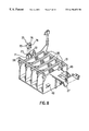
- FIG. 8 shows a service station carriage incorporating a reference mark according to an embodiment of the present invention.
- FIG. 9 shows a service station assembly on which the service station carriage of FIG. 8 is mounted.
- FIG. 10 shows the carriage assembly, including the printer carriage moving in the Y direction along slider rods to the right hand side of the printer where the service station is located.
- FIG. 11A is an isometric view showing the internal components of an optical sensor which is mountable on the printer carriage.
- FIG. 11B is a bottom view of the optical sensor taken along the line 11 B— 11 B of FIG. 11 A.
- FIG. 12 is a front view of the components of the optical sensor of FIG. 11 A.
- FIG. 13 is an enlarged partial perspective view of a part of the optical sensor and a reference mark according to an embodiment of the invention.
- FIG. 14 is a schematic plan view of the reference mark of FIG. 13 .
- FIG. 15A is a schematic representation of the optical sensor readings taken as an optical sensor is scanned over a reference mark.
- FIG. 15B is a schematic representation of the averaged values of the readings of FIG. 15 A.
- FIG. 15C is a schematic representation of the differential of the averaged values of the readings of FIG. 15 B.
- FIG. 16 is a schematic chart showing how the adjustment for bi-directional color printing is extrapolated from data taken from a bi-directional black printing pattern.
- FIGS. 17A, 17 B, and 17 C show a schematic representation of swath height optimized pen alignment.
- FIG. 18 is a schematic showing the use of subset printing patterns to provide relative rather than absolute data measurements.
- FIG. 19 is an exemplary color printout of an actual calibration test pattern incorporating the features of the present invention.
- FIG. 1 shows a perspective schematic view of a thermal inkjet large-format printer having a housing 5 with right and left covers respectively 6 and 7 , mounted on a stand 8 .
- a print media such as paper is positioned along a vertical or media axis by a media axis drive mechanism (not shown).
- the media drive axis is denoted as the X axis and the printer carriage scan axis is denoted as the Y axis.
- the printer has a carriage assembly 9 shown in phantom under cover 6 and more clearly in FIG. 2 which is a perspective view of the print zone of the printer.
- the carriage assembly 9 has a body which is mounted for reciprocal movement along slider rods 11 and 12 and a printer carriage 10 for holding four inkjet cartridges 16 each holding ink of a different colour for example black, yellow, magenta and cyan.
- the cartridges are held in a close packed arrangement and each may be selectively removed from the printer carriage 10 for replacement by a fresh cartridge.
- the printheads of the cartridges 16 are exposed through openings in the printer carriage 10 facing the print media.
- an optical sensor 17 On the side of the printer carriage 10 is mounted an optical sensor 17 which will be described in greater detail below.
- FIG. 3 is a side-bottom perspective view of the carriage assembly 9 which better shows the mounting of the carriage and the protrusion of a printhead 18 of an inkjet cartridge 16 through the printer carriage 10 towards the print media.
- the printer has a set of replaceable ink supply modules 19 in the lefthand side of the printer (shown in phantom under the cover 7 ) and a set of replaceable service station modules mounted in the service station at the right-hand side of the printer (not shown).
- FIG. 4 shows a service station module 20 having three servicing components, namely dual wipers 21 at one end, a spittoon 22 at the other end and a cap 23 at an intermediate position.
- the printer has one service station module 20 per cartridge 16 and each service station module is mounted in a service station carriage 24 , shown in FIG. 5, in the service station unit 25 of the printer.
- the service station carriage 24 has four slots 26 for receiving service modules 20 .
- Each of the slots 26 of the service station carriage 24 has a Z datum ridge 51 (shown in FIG. 8) along a top portion of the slot which engages a corresponding datum ledge 50 (as shown in FIG. 4) along both top edges of the service module 20 .
- Each slot 26 also comprises an upwardly biased spring arm (not shown) which ensures that each service module 20 snaps into place in its respective slot 26 and is held against the datum ridge 51 .
- the service station carriage 24 is mounted within a service station assembly 47 .
- the service station carriage 24 is mounted on two springs 57 within the service station assembly 47 .
- the service station carriage 24 has four pegs 48 , two extending from each of its outer side walls 49 , (shown in FIG. 8) which abut downwardly facing arms 55 extending from the inner side walls 56 (shown in FIG. 9) of the service station assembly 47 .
- the service station carriage 24 is upwardly biased by the springs 57 acting against its base 52 until the pegs 48 on its walls 49 contact the arms 55 of the service station assembly 47 . This provides a “floating” mounting to the service station carriage 24 and allows it to gimbal to some extent to mate with the printer carriage 10 during capping.
- the whole of the service station carriage 24 is moved in two directions, the X and Z directions, by the service station unit 25 so that various of the servicing components of the service modules 20 may be brought up to the printheads 18 of the cartridges 16 when required for servicing.
- the service station assembly 47 is movable in the X direction by a stepper motor 53 which drives a worm drive, and in the Z direction (i.e. the capping direction) by a second stepper motor (not shown) via a linkage 54 .
- the position of the service station carriage 24 in the X and Z directions is determined by counting the steps taken by the stepper motors.
- FIG. 10 shows the carriage assembly, including the printer carriage 10 (shown holding only one rather than four cartridges for clarity) moving in the Y direction along the slider rods 12 and 14 to the right hand side of the printer where the service station is located. Also shown are the service station assembly 47 and the service station carriage 24 holding only one rather than four service modules 20 again for the sake of clarity and the optical sensor 17 .
- the optical sensor 17 includes a photocell 420 , holder 422 , cover 424 , lens 426 , and light source such as two LEDs 428 , 430 .
- a unitary light tube or cap 432 has a pair of notched slots 434 which engage matching tabs on a lower end of the holder 422 upon insertion and relative rotation between the cap and the holder.
- the two LEDs are held in opposite apertures of the two shoulders 438 which have a size slightly less than the outside diameter of the LEDs, to prevent the LEDs from protruding into a central passageway which passes through the holder to the photocell.
- FIGS. 8 and 13 show a two part reference mark formed of an insert 70 and a mount 71 utilised in the presently preferred embodiment of the invention.
- the reference mark is located on the top of the left hand side wall 49 of the service station carriage 24 approximately midway along the length of the wall. This position is chosen so that the reference mark can be easily moved into the path of the optical sensor 17 as it is moved (on the printer carriage 10 ) along the slider bars in the Y direction.
- This movement of the reference mark to a position where it can be utilised for calibration according to the present embodiment is achieved by movement of the service station carriage 24 in the X and Z direction by the service station carriage assembly 47 .
- Other parts of the service station carriage 24 are chosen to be black in colour to ensure that they do not reflect stray light from the optical sensor since such reflections could provide false signals to the optical sensor.
- the longer side of the slot 76 runs perpendicularly to the scanning direction (the Y direction) of the printer carriage 10 so that as the optical sensor 17 of the printer carriage 10 scans past the reference mark the colour change from white to black is “seen” by the sensor (due to the large change in reflectance between a black and a white surface) followed a second colour change from black to white.
- These reflectance or colour changes generate a set of optical sensor readings of the type shown in FIG. 15 where the value of the sensor reading S is plotted against the Y position of the printer carriage 10 to give the curve labelled s 1 (y).
- the central dip 80 in the curve is due to the optical sensor 17 scanning the black band of the mount 71 within the white background of the insert 70 .
- the present technique for aligning a printer carriage with a service station in the carriage scan axis may be utilised at any convenient moment during the operation of the printer to check or recalibrate the location of the printer carriage to the service station.
- the technique may be utilised when a service station component or a component affecting the Y axis of the printer (e.g. the encoder strip) is replaced or serviced.
- the technique may be utilised during the construction or initial assembly of the printer in which case the final calibration is stored within the printer and utilised for the lifetime of the printer.
- the present color test pattern employs a bi-directional color alignment algorithm.
- This algorithm uses a bi-di pattern 200 to measure the different bi-directional offsets for the black and the colors and then optimizes the bi-directional adjustment for all the colors.
- the algorithm measures the offset for the black pen at 2 speeds (low and high) 202 and finds a line that passes for the two offsets, then assumes that the slope will be similar to the other pens (as they have the same architecture and behavior) and measures the color offset at low speed 204 , then it centers the line among the offsets. (See FIG. 16 ).
- the present test pattern technique also uses one pattern 206 to make two different measurements.
- the same pattern is used to make two different measurements: paper axis pen alignment and swath height error measurement.
- Another feature is to print a pattern and scan the printed pattern with minimum dry time.
- some special layout on the patterns has been designed to minimize printing and scanning time. These improvements include print pattern for each pen in the same row, scan the patterns just after printing them, and print the paper axis patterns in the middle of the pinch rollers. This allows for faster scanning and avoids having a dry time.
- Another feature provides swath height optimized paper axis pen alignment. To align the pens in the paper axis, rather than optimize the pen center alignments (which has been the usual approach) we will center the pen extremums to minimize the SH (swath height) differences between pens. So, if the pen is really symmetrical, the result will be the same but if not, the swath heights will be centered on the range. (See FIGS. 17 A- 17 C).
Abstract
Description
Claims (17)
Priority Applications (1)
| Application Number | Priority Date | Filing Date | Title |
|---|---|---|---|
| US09/034,722 US6196652B1 (en) | 1998-03-04 | 1998-03-04 | Scanning an inkjet test pattern for different calibration adjustments |
Applications Claiming Priority (1)
| Application Number | Priority Date | Filing Date | Title |
|---|---|---|---|
| US09/034,722 US6196652B1 (en) | 1998-03-04 | 1998-03-04 | Scanning an inkjet test pattern for different calibration adjustments |
Related Child Applications (1)
| Application Number | Title | Priority Date | Filing Date |
|---|---|---|---|
| US09/770,794 Continuation-In-Part US6386086B2 (en) | 1997-09-12 | 2001-01-29 | Line charge sympathetic detonation arrestor |
Publications (1)
| Publication Number | Publication Date |
|---|---|
| US6196652B1 true US6196652B1 (en) | 2001-03-06 |
Family
ID=21878185
Family Applications (1)
| Application Number | Title | Priority Date | Filing Date |
|---|---|---|---|
| US09/034,722 Expired - Lifetime US6196652B1 (en) | 1998-03-04 | 1998-03-04 | Scanning an inkjet test pattern for different calibration adjustments |
Country Status (1)
| Country | Link |
|---|---|
| US (1) | US6196652B1 (en) |
Cited By (50)
| Publication number | Priority date | Publication date | Assignee | Title |
|---|---|---|---|---|
| US6390587B1 (en) * | 1998-03-04 | 2002-05-21 | Hewlett-Packard Company | Calibration system and method scanning repeated subsets of print test patterns having common color reference markings |
| US6478401B1 (en) | 2001-07-06 | 2002-11-12 | Lexmark International, Inc. | Method for determining vertical misalignment between printer print heads |
| US20030020972A1 (en) * | 2001-07-30 | 2003-01-30 | Francesc Subirada | Compensating for drift and sensor proximity in a scanning sensor, in color calibrating incremental printers |
| US6532026B2 (en) * | 1998-04-03 | 2003-03-11 | Canon Kabushiki Kaisha | Adjustment method of dot printing positions and a printing apparatus |
| US20030058295A1 (en) * | 2001-09-26 | 2003-03-27 | Heiles Tod S. | Printing mechanism swath height and line-feed error compensation |
| US6561613B2 (en) | 2001-10-05 | 2003-05-13 | Lexmark International, Inc. | Method for determining printhead misalignment of a printer |
| US20030112455A1 (en) * | 2001-12-17 | 2003-06-19 | Brother Kogyo Kabushiki Kaisha | Patch forming device |
| GB2384931A (en) * | 2002-01-30 | 2003-08-06 | Hewlett Packard Co | Printer incorporating test pattern scanner |
| US6624876B2 (en) * | 1999-12-21 | 2003-09-23 | Fuji Photo Film Co., Ltd. | Method of printing calibration pattern and printer |
| US6709084B1 (en) * | 2002-10-25 | 2004-03-23 | Hewlett-Packard Development Company, Lp. | Measuring pen-to-paper spacing |
| US20040085378A1 (en) * | 2002-10-31 | 2004-05-06 | Sievert Otto K. | Printing apparatus calibration |
| US20040239708A1 (en) * | 2003-05-30 | 2004-12-02 | Askeland Ronald A. | Disabling ink ejection elements to decrease dot placement artifacts in an inkjet printhead |
| US20050093900A1 (en) * | 2003-10-30 | 2005-05-05 | King David G. | Printhead swath height measurement and compensation for ink jet printing |
| US20050237351A1 (en) * | 2004-04-21 | 2005-10-27 | Hewlett-Packard Development Company, L.P. | Printhead error compensation |
| US20050270325A1 (en) * | 2004-06-07 | 2005-12-08 | Cavill Barry R | System and method for calibrating ink ejecting nozzles in a printer/scanner |
| US20050285889A1 (en) * | 2004-06-23 | 2005-12-29 | Mcgarry Mark | System with alignment information |
| US20060061613A1 (en) * | 2004-09-21 | 2006-03-23 | Z Corporation | Apparatus and methods for servicing 3D printers |
| US20060087528A1 (en) * | 2004-10-27 | 2006-04-27 | Rodenas Josep A | Ink density impact on sensor signal-to-noise ratio |
| US7055925B2 (en) | 2003-07-31 | 2006-06-06 | Hewlett-Packard Development Company, L.P. | Calibration and measurement techniques for printers |
| US20060141145A1 (en) * | 1996-12-20 | 2006-06-29 | Z Corporation | Three-dimensional printer |
| US20060274107A1 (en) * | 2005-06-06 | 2006-12-07 | Lexmark International, Inc. | Method and apparatus for calibrating a printhead |
| US20070070362A1 (en) * | 1998-11-09 | 2007-03-29 | Silverbrook Research Pty Ltd | Printhead assembly with a controller for predetermined pattern printing |
| US20070126157A1 (en) * | 2005-12-02 | 2007-06-07 | Z Corporation | Apparatus and methods for removing printed articles from a 3-D printer |
| US20080042321A1 (en) * | 2003-05-23 | 2008-02-21 | Z Corporation | Apparatus and Methods for 3D Printing |
| US20080060330A1 (en) * | 2006-05-26 | 2008-03-13 | Z Corporation | Apparatus and methods for handling materials in a 3-D printer |
| US20080252682A1 (en) * | 2004-09-21 | 2008-10-16 | Z Corporation | Apparatus and Methods for Servicing 3D Printers |
| US20090011066A1 (en) * | 1996-12-20 | 2009-01-08 | Z Corporation | Three-Dimensional Printer |
| US20090021595A1 (en) * | 2007-07-17 | 2009-01-22 | Ali Zandifar | Low Memory Auto-Focus and Exposure System for Large Multi-Frame Image Acquisition |
| US20090066971A1 (en) * | 2007-09-06 | 2009-03-12 | Ali Zandifar | Characterization of a Printed Droplet |
| WO2012055553A1 (en) | 2010-10-27 | 2012-05-03 | Technoform Glass Insulation Holding Gmbh | Spacer profile and insulating pane unit with a spacer profile of this type |
| DE102011009359A1 (en) | 2011-01-25 | 2012-07-26 | Technoform Glass Insulation Holding Gmbh | Spacer profile and insulating disk unit with such a spacer profile |
| US8376516B2 (en) | 2010-04-06 | 2013-02-19 | Xerox Corporation | System and method for operating a web printing system to compensate for dimensional changes in the web |
| US8585173B2 (en) | 2011-02-14 | 2013-11-19 | Xerox Corporation | Test pattern less perceptible to human observation and method of analysis of image data corresponding to the test pattern in an inkjet printer |
| US8602518B2 (en) | 2010-04-06 | 2013-12-10 | Xerox Corporation | Test pattern effective for coarse registration of inkjet printheads and methods of analysis of image data corresponding to the test pattern in an inkjet printer |
| US8662625B2 (en) | 2012-02-08 | 2014-03-04 | Xerox Corporation | Method of printhead calibration between multiple printheads |
| US8721026B2 (en) | 2010-05-17 | 2014-05-13 | Xerox Corporation | Method for identifying and verifying dash structures as candidates for test patterns and replacement patterns in an inkjet printer |
| US8721033B2 (en) | 2010-04-06 | 2014-05-13 | Xerox Corporation | Method for analyzing image data corresponding to a test pattern effective for fine registration of inkjet printheads in an inkjet printer |
| US8764149B1 (en) | 2013-01-17 | 2014-07-01 | Xerox Corporation | System and method for process direction registration of inkjets in a printer operating with a high speed image receiving surface |
| US8888225B2 (en) | 2013-04-19 | 2014-11-18 | Xerox Corporation | Method for calibrating optical detector operation with marks formed on a moving image receiving surface in a printer |
| US9067445B2 (en) | 2013-09-17 | 2015-06-30 | Xerox Corporation | System and method of printhead calibration with reduced number of active inkjets |
| US9375962B1 (en) | 2015-06-23 | 2016-06-28 | Xerox Corporation | System and method for identification of marks in printed test patterns |
| US20170036457A1 (en) * | 2014-04-16 | 2017-02-09 | Mimaki Engineering Co., Ltd. | Inkjet printer and printing method |
| US9844961B1 (en) | 2016-10-27 | 2017-12-19 | Xerox Corporation | System and method for analysis of low-contrast ink test patterns in inkjet printers |
| WO2018063158A1 (en) * | 2016-09-27 | 2018-04-05 | Hewlett-Packard Development Company, L.P. | Print pattern & algorithm for automatic ink mix detection |
| US9962931B2 (en) | 2015-02-18 | 2018-05-08 | Hewlett-Packard Development Company, L.P. | Estimation of pen to paper spacing |
| US10011108B2 (en) | 2015-02-13 | 2018-07-03 | Hewlett-Packard Development Company, L.P. | Printer and computer-implemented process for controlling a printer |
| WO2020096616A1 (en) * | 2018-11-09 | 2020-05-14 | Hewlett-Packard Development Company, L.P. | Alterations of print drive assemblies |
| US10919310B1 (en) | 2019-12-05 | 2021-02-16 | Xerox Corporation | Methods for operating printhead inkjets to attenuate ink drying in the inkjets during printing operations |
| WO2022256034A1 (en) * | 2021-05-31 | 2022-12-08 | Hewlett-Packard Development Company, L.P. | Calibration of print engine margin using scanner |
| US11932012B2 (en) | 2022-03-11 | 2024-03-19 | Xerox Corporation | System and method for operating an inkjet printer to attenuate ink drying in the inkjets during printing operations |
Citations (9)
| Publication number | Priority date | Publication date | Assignee | Title |
|---|---|---|---|---|
| US5451990A (en) * | 1993-04-30 | 1995-09-19 | Hewlett-Packard Company | Reference pattern for use in aligning multiple inkjet cartridges |
| US5534895A (en) * | 1994-06-30 | 1996-07-09 | Xerox Corporation | Electronic auto-correction of misaligned segmented printbars |
| US5539434A (en) * | 1992-05-06 | 1996-07-23 | Fuji Xerox Co., Ltd. | Ink jet recording apparatus and method therefor |
| US5598272A (en) * | 1994-04-07 | 1997-01-28 | Imation, Inc. | Visual calibrator for color halftone imaging |
| US5600350A (en) * | 1993-04-30 | 1997-02-04 | Hewlett-Packard Company | Multiple inkjet print cartridge alignment by scanning a reference pattern and sampling same with reference to a position encoder |
| US5796414A (en) * | 1996-03-25 | 1998-08-18 | Hewlett-Packard Company | Systems and method for establishing positional accuracy in two dimensions based on a sensor scan in one dimension |
| US5798773A (en) * | 1991-02-20 | 1998-08-25 | Canon Kabushiki Kaisha | Recording apparatus and method for correction of discharge failure and density unevenness |
| US5835108A (en) * | 1996-09-25 | 1998-11-10 | Hewlett-Packard Company | Calibration technique for mis-directed inkjet printhead nozzles |
| US5847722A (en) * | 1995-11-21 | 1998-12-08 | Hewlett-Packard Company | Inkjet printhead alignment via measurement and entry |
-
1998
- 1998-03-04 US US09/034,722 patent/US6196652B1/en not_active Expired - Lifetime
Patent Citations (9)
| Publication number | Priority date | Publication date | Assignee | Title |
|---|---|---|---|---|
| US5798773A (en) * | 1991-02-20 | 1998-08-25 | Canon Kabushiki Kaisha | Recording apparatus and method for correction of discharge failure and density unevenness |
| US5539434A (en) * | 1992-05-06 | 1996-07-23 | Fuji Xerox Co., Ltd. | Ink jet recording apparatus and method therefor |
| US5451990A (en) * | 1993-04-30 | 1995-09-19 | Hewlett-Packard Company | Reference pattern for use in aligning multiple inkjet cartridges |
| US5600350A (en) * | 1993-04-30 | 1997-02-04 | Hewlett-Packard Company | Multiple inkjet print cartridge alignment by scanning a reference pattern and sampling same with reference to a position encoder |
| US5598272A (en) * | 1994-04-07 | 1997-01-28 | Imation, Inc. | Visual calibrator for color halftone imaging |
| US5534895A (en) * | 1994-06-30 | 1996-07-09 | Xerox Corporation | Electronic auto-correction of misaligned segmented printbars |
| US5847722A (en) * | 1995-11-21 | 1998-12-08 | Hewlett-Packard Company | Inkjet printhead alignment via measurement and entry |
| US5796414A (en) * | 1996-03-25 | 1998-08-18 | Hewlett-Packard Company | Systems and method for establishing positional accuracy in two dimensions based on a sensor scan in one dimension |
| US5835108A (en) * | 1996-09-25 | 1998-11-10 | Hewlett-Packard Company | Calibration technique for mis-directed inkjet printhead nozzles |
Cited By (84)
| Publication number | Priority date | Publication date | Assignee | Title |
|---|---|---|---|---|
| US20090011066A1 (en) * | 1996-12-20 | 2009-01-08 | Z Corporation | Three-Dimensional Printer |
| US8017055B2 (en) | 1996-12-20 | 2011-09-13 | Z Corporation | Three-dimensional printer |
| US7686995B2 (en) | 1996-12-20 | 2010-03-30 | Z Corporation | Three-dimensional printer |
| US20060141145A1 (en) * | 1996-12-20 | 2006-06-29 | Z Corporation | Three-dimensional printer |
| US20100151136A1 (en) * | 1996-12-20 | 2010-06-17 | Z Corporation | Three-Dimensional Printer |
| US6390587B1 (en) * | 1998-03-04 | 2002-05-21 | Hewlett-Packard Company | Calibration system and method scanning repeated subsets of print test patterns having common color reference markings |
| US6532026B2 (en) * | 1998-04-03 | 2003-03-11 | Canon Kabushiki Kaisha | Adjustment method of dot printing positions and a printing apparatus |
| US20070070362A1 (en) * | 1998-11-09 | 2007-03-29 | Silverbrook Research Pty Ltd | Printhead assembly with a controller for predetermined pattern printing |
| US7433073B2 (en) * | 1998-11-09 | 2008-10-07 | Silverbrook Research Pty Ltd | Printhead assembly with a controller for predetermined pattern printing |
| US6624876B2 (en) * | 1999-12-21 | 2003-09-23 | Fuji Photo Film Co., Ltd. | Method of printing calibration pattern and printer |
| US6478401B1 (en) | 2001-07-06 | 2002-11-12 | Lexmark International, Inc. | Method for determining vertical misalignment between printer print heads |
| US7023581B2 (en) * | 2001-07-30 | 2006-04-04 | Hewlett-Packard Development Company, L.P. | Compensating for drift and sensor proximity in a scanning sensor, in color calibrating incremental printers |
| US20030020972A1 (en) * | 2001-07-30 | 2003-01-30 | Francesc Subirada | Compensating for drift and sensor proximity in a scanning sensor, in color calibrating incremental printers |
| GB2380161A (en) * | 2001-09-26 | 2003-04-02 | Hewlett Packard Co | Determining a print media line-feed advance offset/error compensation from pen swath densities detected from a printed image |
| US20030058295A1 (en) * | 2001-09-26 | 2003-03-27 | Heiles Tod S. | Printing mechanism swath height and line-feed error compensation |
| US6561613B2 (en) | 2001-10-05 | 2003-05-13 | Lexmark International, Inc. | Method for determining printhead misalignment of a printer |
| US20030112455A1 (en) * | 2001-12-17 | 2003-06-19 | Brother Kogyo Kabushiki Kaisha | Patch forming device |
| US7317554B2 (en) * | 2001-12-17 | 2008-01-08 | Brother Kogyo Kabushiki Kaisha | Patch forming device |
| US6802580B2 (en) | 2002-01-30 | 2004-10-12 | Hewlett-Packard Development Company, L.P. | Printer device and method |
| US20030218650A1 (en) * | 2002-01-30 | 2003-11-27 | Valero Jose Luis | Printer device and method |
| GB2384931A (en) * | 2002-01-30 | 2003-08-06 | Hewlett Packard Co | Printer incorporating test pattern scanner |
| GB2384931B (en) * | 2002-01-30 | 2005-06-29 | Hewlett Packard Co | Printer device and method |
| US6709084B1 (en) * | 2002-10-25 | 2004-03-23 | Hewlett-Packard Development Company, Lp. | Measuring pen-to-paper spacing |
| US20040085378A1 (en) * | 2002-10-31 | 2004-05-06 | Sievert Otto K. | Printing apparatus calibration |
| US6883892B2 (en) | 2002-10-31 | 2005-04-26 | Hewlett-Packard Development Company, L.P. | Printing apparatus calibration |
| US20080042321A1 (en) * | 2003-05-23 | 2008-02-21 | Z Corporation | Apparatus and Methods for 3D Printing |
| US20040239708A1 (en) * | 2003-05-30 | 2004-12-02 | Askeland Ronald A. | Disabling ink ejection elements to decrease dot placement artifacts in an inkjet printhead |
| US6832823B1 (en) * | 2003-05-30 | 2004-12-21 | Hewlett-Packard Development Company, L.P. | Disabling ink ejection elements to decrease dot placement artifacts in an inkjet printhead |
| US7055925B2 (en) | 2003-07-31 | 2006-06-06 | Hewlett-Packard Development Company, L.P. | Calibration and measurement techniques for printers |
| US7036904B2 (en) | 2003-10-30 | 2006-05-02 | Lexmark International, Inc. | Printhead swath height measurement and compensation for ink jet printing |
| US20050093900A1 (en) * | 2003-10-30 | 2005-05-05 | King David G. | Printhead swath height measurement and compensation for ink jet printing |
| US20050237351A1 (en) * | 2004-04-21 | 2005-10-27 | Hewlett-Packard Development Company, L.P. | Printhead error compensation |
| US7708362B2 (en) | 2004-04-21 | 2010-05-04 | Hewlett-Packard Development Company, L.P. | Printhead error compensation |
| US20050270325A1 (en) * | 2004-06-07 | 2005-12-08 | Cavill Barry R | System and method for calibrating ink ejecting nozzles in a printer/scanner |
| US7273262B2 (en) | 2004-06-23 | 2007-09-25 | Hewlett-Packard Development Company, L.P. | System with alignment information |
| EP1609602A3 (en) * | 2004-06-23 | 2007-05-09 | Hewlett-Packard Development Company, L.P. | System with alignment information |
| US20050285889A1 (en) * | 2004-06-23 | 2005-12-29 | Mcgarry Mark | System with alignment information |
| US20110032301A1 (en) * | 2004-09-21 | 2011-02-10 | Z Corporation | Apparatus and methods for servicing 3d printers |
| US7824001B2 (en) | 2004-09-21 | 2010-11-02 | Z Corporation | Apparatus and methods for servicing 3D printers |
| US8167395B2 (en) | 2004-09-21 | 2012-05-01 | 3D Systems, Inc. | Apparatus and methods for servicing 3D printers |
| US20060061613A1 (en) * | 2004-09-21 | 2006-03-23 | Z Corporation | Apparatus and methods for servicing 3D printers |
| US20080252682A1 (en) * | 2004-09-21 | 2008-10-16 | Z Corporation | Apparatus and Methods for Servicing 3D Printers |
| US7431417B2 (en) * | 2004-10-27 | 2008-10-07 | Hewlett-Packard Development Company, L.P. | Ink density impact on sensor signal-to-noise ratio |
| US20060087528A1 (en) * | 2004-10-27 | 2006-04-27 | Rodenas Josep A | Ink density impact on sensor signal-to-noise ratio |
| US20060274107A1 (en) * | 2005-06-06 | 2006-12-07 | Lexmark International, Inc. | Method and apparatus for calibrating a printhead |
| US7380897B2 (en) | 2005-06-06 | 2008-06-03 | Lexmark International, Inc. | Method and apparatus for calibrating a printhead |
| US20070126157A1 (en) * | 2005-12-02 | 2007-06-07 | Z Corporation | Apparatus and methods for removing printed articles from a 3-D printer |
| US8185229B2 (en) | 2006-05-26 | 2012-05-22 | 3D Systems, Inc. | Apparatus and methods for handling materials in a 3-D printer |
| US20080060330A1 (en) * | 2006-05-26 | 2008-03-13 | Z Corporation | Apparatus and methods for handling materials in a 3-D printer |
| US7828022B2 (en) | 2006-05-26 | 2010-11-09 | Z Corporation | Apparatus and methods for handling materials in a 3-D printer |
| US20110233808A1 (en) * | 2006-05-26 | 2011-09-29 | Z Corporation | Apparatus and methods for handling materials in a 3-d printer |
| US7971991B2 (en) | 2006-05-26 | 2011-07-05 | Z Corporation | Apparatus and methods for handling materials in a 3-D printer |
| US7979152B2 (en) | 2006-05-26 | 2011-07-12 | Z Corporation | Apparatus and methods for handling materials in a 3-D printer |
| US20110211016A1 (en) * | 2006-05-26 | 2011-09-01 | Z Corporation | Apparatus and methods for handling materials in a 3-d printer |
| US20090021595A1 (en) * | 2007-07-17 | 2009-01-22 | Ali Zandifar | Low Memory Auto-Focus and Exposure System for Large Multi-Frame Image Acquisition |
| US7969475B2 (en) | 2007-07-17 | 2011-06-28 | Seiko Epson Corporation | Low memory auto-focus and exposure system for large multi-frame image acquisition |
| US7783107B2 (en) | 2007-09-06 | 2010-08-24 | Seiko Epson Corporation | Characterization of a printed droplet |
| US20090066971A1 (en) * | 2007-09-06 | 2009-03-12 | Ali Zandifar | Characterization of a Printed Droplet |
| US8602518B2 (en) | 2010-04-06 | 2013-12-10 | Xerox Corporation | Test pattern effective for coarse registration of inkjet printheads and methods of analysis of image data corresponding to the test pattern in an inkjet printer |
| US8721033B2 (en) | 2010-04-06 | 2014-05-13 | Xerox Corporation | Method for analyzing image data corresponding to a test pattern effective for fine registration of inkjet printheads in an inkjet printer |
| US8376516B2 (en) | 2010-04-06 | 2013-02-19 | Xerox Corporation | System and method for operating a web printing system to compensate for dimensional changes in the web |
| US8721026B2 (en) | 2010-05-17 | 2014-05-13 | Xerox Corporation | Method for identifying and verifying dash structures as candidates for test patterns and replacement patterns in an inkjet printer |
| DE102010049806A1 (en) | 2010-10-27 | 2012-05-03 | Technoform Glass Insulation Holding Gmbh | Spacer profile and insulating disk unit with such a spacer profile |
| EP3162999A2 (en) | 2010-10-27 | 2017-05-03 | Technoform Glass Insulation Holding GmbH | Profiled spacer and insulation glazing assembly with such a profiled spacer |
| WO2012055553A1 (en) | 2010-10-27 | 2012-05-03 | Technoform Glass Insulation Holding Gmbh | Spacer profile and insulating pane unit with a spacer profile of this type |
| DE102011009359A1 (en) | 2011-01-25 | 2012-07-26 | Technoform Glass Insulation Holding Gmbh | Spacer profile and insulating disk unit with such a spacer profile |
| US8585173B2 (en) | 2011-02-14 | 2013-11-19 | Xerox Corporation | Test pattern less perceptible to human observation and method of analysis of image data corresponding to the test pattern in an inkjet printer |
| US8662625B2 (en) | 2012-02-08 | 2014-03-04 | Xerox Corporation | Method of printhead calibration between multiple printheads |
| US8764149B1 (en) | 2013-01-17 | 2014-07-01 | Xerox Corporation | System and method for process direction registration of inkjets in a printer operating with a high speed image receiving surface |
| US8888225B2 (en) | 2013-04-19 | 2014-11-18 | Xerox Corporation | Method for calibrating optical detector operation with marks formed on a moving image receiving surface in a printer |
| US9067445B2 (en) | 2013-09-17 | 2015-06-30 | Xerox Corporation | System and method of printhead calibration with reduced number of active inkjets |
| US10035359B2 (en) * | 2014-04-16 | 2018-07-31 | Mimaki Engineering Co., Ltd. | Inkjet printer and printing method |
| US20170036457A1 (en) * | 2014-04-16 | 2017-02-09 | Mimaki Engineering Co., Ltd. | Inkjet printer and printing method |
| US10532559B2 (en) | 2015-02-13 | 2020-01-14 | Hewlett-Packard Development Company, L.P. | Printer and computer-implemented process for controlling a printer |
| US10011108B2 (en) | 2015-02-13 | 2018-07-03 | Hewlett-Packard Development Company, L.P. | Printer and computer-implemented process for controlling a printer |
| US9962931B2 (en) | 2015-02-18 | 2018-05-08 | Hewlett-Packard Development Company, L.P. | Estimation of pen to paper spacing |
| US9375962B1 (en) | 2015-06-23 | 2016-06-28 | Xerox Corporation | System and method for identification of marks in printed test patterns |
| WO2018063158A1 (en) * | 2016-09-27 | 2018-04-05 | Hewlett-Packard Development Company, L.P. | Print pattern & algorithm for automatic ink mix detection |
| US10870282B2 (en) | 2016-09-27 | 2020-12-22 | Hewlett-Packard Development Company, L.P. | Print pattern and algorithm for automatic ink mix detection |
| US9844961B1 (en) | 2016-10-27 | 2017-12-19 | Xerox Corporation | System and method for analysis of low-contrast ink test patterns in inkjet printers |
| WO2020096616A1 (en) * | 2018-11-09 | 2020-05-14 | Hewlett-Packard Development Company, L.P. | Alterations of print drive assemblies |
| US10919310B1 (en) | 2019-12-05 | 2021-02-16 | Xerox Corporation | Methods for operating printhead inkjets to attenuate ink drying in the inkjets during printing operations |
| WO2022256034A1 (en) * | 2021-05-31 | 2022-12-08 | Hewlett-Packard Development Company, L.P. | Calibration of print engine margin using scanner |
| US11932012B2 (en) | 2022-03-11 | 2024-03-19 | Xerox Corporation | System and method for operating an inkjet printer to attenuate ink drying in the inkjets during printing operations |
Similar Documents
| Publication | Publication Date | Title |
|---|---|---|
| US6196652B1 (en) | Scanning an inkjet test pattern for different calibration adjustments | |
| US6164750A (en) | Automated test pattern technique using accelerated sequence of color printing and optical scanning | |
| US6390587B1 (en) | Calibration system and method scanning repeated subsets of print test patterns having common color reference markings | |
| EP0775587B1 (en) | Inkjet printhead alignment via measurement and entry | |
| US5975674A (en) | Optical path optimization for light transmission and reflection in a carriage-mounted inkjet printer sensor | |
| US6352331B1 (en) | Detection of non-firing printhead nozzles by optical scanning of a test pattern | |
| US5109239A (en) | Inter pen offset determination and compensation in multi-pen ink jet printing systems | |
| US6164753A (en) | Optical sensor system to calibrate a printhead servicing location in an inkjet printer | |
| JP3343291B2 (en) | Device for aligning inkjet cartridges | |
| US4922270A (en) | Inter pen offset determination and compensation in multi-pen thermal ink jet pen printing systems | |
| US6471329B1 (en) | Inkjet printhead capping method and apparatus | |
| US6767075B1 (en) | Image forming device | |
| US5796414A (en) | Systems and method for establishing positional accuracy in two dimensions based on a sensor scan in one dimension | |
| US6199973B1 (en) | Storage container for inkjet cartridges having removable capping means and a method for storing inkjet cartridges | |
| EP1029692B9 (en) | Printing apparatus | |
| US5036340A (en) | Piezoelectric detector for drop position determination in multi-pen ink jet printing systems | |
| JP2933347B2 (en) | Inkjet print head | |
| US4922268A (en) | Piezoelectric detector for drop position determination in multi-pen thermal ink jet pen printing systems | |
| JP2004001558A (en) | Device for arranging inkjet cartridge | |
| US5905512A (en) | Unitary light tube for mounting optical sensor components on an inkjet printer carriage | |
| KR19990063071A (en) | Check the thermal inkjet printer cartridge | |
| US5568172A (en) | Printing method and apparatus for registering dots | |
| US6172690B1 (en) | Stray light compensating unitary light tube for mounting optical sensor components on an ink-jet printer carriage | |
| US20030113152A1 (en) | Automatic horizontal and vertical head-to-head alignment method and sensor for an ink jet printer | |
| US6132037A (en) | Storage container for inkjet cartridges having cleaning means and a method for storing inkjet cartridges |
Legal Events
| Date | Code | Title | Description |
|---|---|---|---|
| AS | Assignment |
Owner name: HEWLETT-PACKARD COMPANY, CALIFORNIA Free format text: ASSIGNMENT OF ASSIGNORS INTEREST;ASSIGNOR:HEWLETT-PACKARD ESPANOLA, S.A.;REEL/FRAME:009518/0124 Effective date: 19981005 |
|
| AS | Assignment |
Owner name: HEWLETT-PACKARD COMPANY, COLORADO Free format text: MERGER;ASSIGNOR:HEWLETT-PACKARD COMPANY;REEL/FRAME:011523/0469 Effective date: 19980520 |
|
| STCF | Information on status: patent grant |
Free format text: PATENTED CASE |
|
| FEPP | Fee payment procedure |
Free format text: PAYOR NUMBER ASSIGNED (ORIGINAL EVENT CODE: ASPN); ENTITY STATUS OF PATENT OWNER: LARGE ENTITY |
|
| FPAY | Fee payment |
Year of fee payment: 4 |
|
| FPAY | Fee payment |
Year of fee payment: 8 |
|
| REMI | Maintenance fee reminder mailed | ||
| AS | Assignment |
Owner name: HEWLETT-PACKARD DEVELOPMENT COMPANY, L.P., TEXAS Free format text: ASSIGNMENT OF ASSIGNORS INTEREST;ASSIGNOR:HEWLETT-PACKARD COMPANY;REEL/FRAME:026945/0699 Effective date: 20030131 |
|
| FPAY | Fee payment |
Year of fee payment: 12 |