US6200282B1 - Massage machine of chair type - Google Patents
Massage machine of chair type Download PDFInfo
- Publication number
- US6200282B1 US6200282B1 US08/863,070 US86307097A US6200282B1 US 6200282 B1 US6200282 B1 US 6200282B1 US 86307097 A US86307097 A US 86307097A US 6200282 B1 US6200282 B1 US 6200282B1
- Authority
- US
- United States
- Prior art keywords
- massage
- finger
- user
- finger drive
- therapeutic
- Prior art date
- Legal status (The legal status is an assumption and is not a legal conclusion. Google has not performed a legal analysis and makes no representation as to the accuracy of the status listed.)
- Expired - Fee Related
Links
- 230000001225 therapeutic effect Effects 0.000 claims abstract description 45
- 238000010079 rubber tapping Methods 0.000 claims abstract description 20
- 108010076504 Protein Sorting Signals Proteins 0.000 claims 2
- 238000010586 diagram Methods 0.000 description 7
- 238000010276 construction Methods 0.000 description 6
- 230000007246 mechanism Effects 0.000 description 4
- 238000004898 kneading Methods 0.000 description 3
- 210000003205 muscle Anatomy 0.000 description 2
- 230000009471 action Effects 0.000 description 1
- 230000004075 alteration Effects 0.000 description 1
- 230000003247 decreasing effect Effects 0.000 description 1
- 230000000694 effects Effects 0.000 description 1
- 230000004048 modification Effects 0.000 description 1
- 238000012986 modification Methods 0.000 description 1
- 230000002035 prolonged effect Effects 0.000 description 1
- 230000009467 reduction Effects 0.000 description 1
- 230000004936 stimulating effect Effects 0.000 description 1
- 230000000638 stimulation Effects 0.000 description 1
Images


Classifications
-
- A—HUMAN NECESSITIES
- A61—MEDICAL OR VETERINARY SCIENCE; HYGIENE
- A61H—PHYSICAL THERAPY APPARATUS, e.g. DEVICES FOR LOCATING OR STIMULATING REFLEX POINTS IN THE BODY; ARTIFICIAL RESPIRATION; MASSAGE; BATHING DEVICES FOR SPECIAL THERAPEUTIC OR HYGIENIC PURPOSES OR SPECIFIC PARTS OF THE BODY
- A61H7/00—Devices for suction-kneading massage; Devices for massaging the skin by rubbing or brushing not otherwise provided for
- A61H7/007—Kneading
-
- A—HUMAN NECESSITIES
- A61—MEDICAL OR VETERINARY SCIENCE; HYGIENE
- A61H—PHYSICAL THERAPY APPARATUS, e.g. DEVICES FOR LOCATING OR STIMULATING REFLEX POINTS IN THE BODY; ARTIFICIAL RESPIRATION; MASSAGE; BATHING DEVICES FOR SPECIAL THERAPEUTIC OR HYGIENIC PURPOSES OR SPECIFIC PARTS OF THE BODY
- A61H23/00—Percussion or vibration massage, e.g. using supersonic vibration; Suction-vibration massage; Massage with moving diaphragms
- A61H23/006—Percussion or tapping massage
-
- A—HUMAN NECESSITIES
- A61—MEDICAL OR VETERINARY SCIENCE; HYGIENE
- A61H—PHYSICAL THERAPY APPARATUS, e.g. DEVICES FOR LOCATING OR STIMULATING REFLEX POINTS IN THE BODY; ARTIFICIAL RESPIRATION; MASSAGE; BATHING DEVICES FOR SPECIAL THERAPEUTIC OR HYGIENIC PURPOSES OR SPECIFIC PARTS OF THE BODY
- A61H7/00—Devices for suction-kneading massage; Devices for massaging the skin by rubbing or brushing not otherwise provided for
- A61H7/007—Kneading
- A61H2007/009—Kneading having massage elements rotating on parallel output axis
-
- A—HUMAN NECESSITIES
- A61—MEDICAL OR VETERINARY SCIENCE; HYGIENE
- A61H—PHYSICAL THERAPY APPARATUS, e.g. DEVICES FOR LOCATING OR STIMULATING REFLEX POINTS IN THE BODY; ARTIFICIAL RESPIRATION; MASSAGE; BATHING DEVICES FOR SPECIAL THERAPEUTIC OR HYGIENIC PURPOSES OR SPECIFIC PARTS OF THE BODY
- A61H2201/00—Characteristics of apparatus not provided for in the preceding codes
- A61H2201/01—Constructive details
- A61H2201/0119—Support for the device
- A61H2201/0138—Support for the device incorporated in furniture
- A61H2201/0149—Seat or chair
-
- A—HUMAN NECESSITIES
- A61—MEDICAL OR VETERINARY SCIENCE; HYGIENE
- A61H—PHYSICAL THERAPY APPARATUS, e.g. DEVICES FOR LOCATING OR STIMULATING REFLEX POINTS IN THE BODY; ARTIFICIAL RESPIRATION; MASSAGE; BATHING DEVICES FOR SPECIAL THERAPEUTIC OR HYGIENIC PURPOSES OR SPECIFIC PARTS OF THE BODY
- A61H2201/00—Characteristics of apparatus not provided for in the preceding codes
- A61H2201/12—Driving means
- A61H2201/1207—Driving means with electric or magnetic drive
- A61H2201/1215—Rotary drive
-
- A—HUMAN NECESSITIES
- A61—MEDICAL OR VETERINARY SCIENCE; HYGIENE
- A61H—PHYSICAL THERAPY APPARATUS, e.g. DEVICES FOR LOCATING OR STIMULATING REFLEX POINTS IN THE BODY; ARTIFICIAL RESPIRATION; MASSAGE; BATHING DEVICES FOR SPECIAL THERAPEUTIC OR HYGIENIC PURPOSES OR SPECIFIC PARTS OF THE BODY
- A61H2201/00—Characteristics of apparatus not provided for in the preceding codes
- A61H2201/16—Physical interface with patient
- A61H2201/1602—Physical interface with patient kind of interface, e.g. head rest, knee support or lumbar support
- A61H2201/1614—Shoulder, e.g. for neck stretching
-
- A—HUMAN NECESSITIES
- A61—MEDICAL OR VETERINARY SCIENCE; HYGIENE
- A61H—PHYSICAL THERAPY APPARATUS, e.g. DEVICES FOR LOCATING OR STIMULATING REFLEX POINTS IN THE BODY; ARTIFICIAL RESPIRATION; MASSAGE; BATHING DEVICES FOR SPECIAL THERAPEUTIC OR HYGIENIC PURPOSES OR SPECIFIC PARTS OF THE BODY
- A61H2201/00—Characteristics of apparatus not provided for in the preceding codes
- A61H2201/16—Physical interface with patient
- A61H2201/1602—Physical interface with patient kind of interface, e.g. head rest, knee support or lumbar support
- A61H2201/1623—Back
-
- A—HUMAN NECESSITIES
- A61—MEDICAL OR VETERINARY SCIENCE; HYGIENE
- A61H—PHYSICAL THERAPY APPARATUS, e.g. DEVICES FOR LOCATING OR STIMULATING REFLEX POINTS IN THE BODY; ARTIFICIAL RESPIRATION; MASSAGE; BATHING DEVICES FOR SPECIAL THERAPEUTIC OR HYGIENIC PURPOSES OR SPECIFIC PARTS OF THE BODY
- A61H2201/00—Characteristics of apparatus not provided for in the preceding codes
- A61H2201/16—Physical interface with patient
- A61H2201/1602—Physical interface with patient kind of interface, e.g. head rest, knee support or lumbar support
- A61H2201/1628—Pelvis
-
- A—HUMAN NECESSITIES
- A61—MEDICAL OR VETERINARY SCIENCE; HYGIENE
- A61H—PHYSICAL THERAPY APPARATUS, e.g. DEVICES FOR LOCATING OR STIMULATING REFLEX POINTS IN THE BODY; ARTIFICIAL RESPIRATION; MASSAGE; BATHING DEVICES FOR SPECIAL THERAPEUTIC OR HYGIENIC PURPOSES OR SPECIFIC PARTS OF THE BODY
- A61H2201/00—Characteristics of apparatus not provided for in the preceding codes
- A61H2201/16—Physical interface with patient
- A61H2201/1602—Physical interface with patient kind of interface, e.g. head rest, knee support or lumbar support
- A61H2201/164—Feet or leg, e.g. pedal
-
- A—HUMAN NECESSITIES
- A61—MEDICAL OR VETERINARY SCIENCE; HYGIENE
- A61H—PHYSICAL THERAPY APPARATUS, e.g. DEVICES FOR LOCATING OR STIMULATING REFLEX POINTS IN THE BODY; ARTIFICIAL RESPIRATION; MASSAGE; BATHING DEVICES FOR SPECIAL THERAPEUTIC OR HYGIENIC PURPOSES OR SPECIFIC PARTS OF THE BODY
- A61H2201/00—Characteristics of apparatus not provided for in the preceding codes
- A61H2201/16—Physical interface with patient
- A61H2201/1657—Movement of interface, i.e. force application means
- A61H2201/1664—Movement of interface, i.e. force application means linear
- A61H2201/1669—Movement of interface, i.e. force application means linear moving along the body in a reciprocating manner
-
- A—HUMAN NECESSITIES
- A61—MEDICAL OR VETERINARY SCIENCE; HYGIENE
- A61H—PHYSICAL THERAPY APPARATUS, e.g. DEVICES FOR LOCATING OR STIMULATING REFLEX POINTS IN THE BODY; ARTIFICIAL RESPIRATION; MASSAGE; BATHING DEVICES FOR SPECIAL THERAPEUTIC OR HYGIENIC PURPOSES OR SPECIFIC PARTS OF THE BODY
- A61H2201/00—Characteristics of apparatus not provided for in the preceding codes
- A61H2201/16—Physical interface with patient
- A61H2201/1657—Movement of interface, i.e. force application means
- A61H2201/1676—Pivoting
- A61H2201/1678—Means for angularly oscillating massage elements
-
- A—HUMAN NECESSITIES
- A61—MEDICAL OR VETERINARY SCIENCE; HYGIENE
- A61H—PHYSICAL THERAPY APPARATUS, e.g. DEVICES FOR LOCATING OR STIMULATING REFLEX POINTS IN THE BODY; ARTIFICIAL RESPIRATION; MASSAGE; BATHING DEVICES FOR SPECIAL THERAPEUTIC OR HYGIENIC PURPOSES OR SPECIFIC PARTS OF THE BODY
- A61H2201/00—Characteristics of apparatus not provided for in the preceding codes
- A61H2201/50—Control means thereof
- A61H2201/5002—Means for controlling a set of similar massage devices acting in sequence at different locations on a patient
-
- A—HUMAN NECESSITIES
- A61—MEDICAL OR VETERINARY SCIENCE; HYGIENE
- A61H—PHYSICAL THERAPY APPARATUS, e.g. DEVICES FOR LOCATING OR STIMULATING REFLEX POINTS IN THE BODY; ARTIFICIAL RESPIRATION; MASSAGE; BATHING DEVICES FOR SPECIAL THERAPEUTIC OR HYGIENIC PURPOSES OR SPECIFIC PARTS OF THE BODY
- A61H2201/00—Characteristics of apparatus not provided for in the preceding codes
- A61H2201/50—Control means thereof
- A61H2201/5058—Sensors or detectors
- A61H2201/5064—Position sensors
- A61H2201/5066—Limit switches
-
- A—HUMAN NECESSITIES
- A61—MEDICAL OR VETERINARY SCIENCE; HYGIENE
- A61H—PHYSICAL THERAPY APPARATUS, e.g. DEVICES FOR LOCATING OR STIMULATING REFLEX POINTS IN THE BODY; ARTIFICIAL RESPIRATION; MASSAGE; BATHING DEVICES FOR SPECIAL THERAPEUTIC OR HYGIENIC PURPOSES OR SPECIFIC PARTS OF THE BODY
- A61H2205/00—Devices for specific parts of the body
- A61H2205/06—Arms
- A61H2205/062—Shoulders
-
- A—HUMAN NECESSITIES
- A61—MEDICAL OR VETERINARY SCIENCE; HYGIENE
- A61H—PHYSICAL THERAPY APPARATUS, e.g. DEVICES FOR LOCATING OR STIMULATING REFLEX POINTS IN THE BODY; ARTIFICIAL RESPIRATION; MASSAGE; BATHING DEVICES FOR SPECIAL THERAPEUTIC OR HYGIENIC PURPOSES OR SPECIFIC PARTS OF THE BODY
- A61H2205/00—Devices for specific parts of the body
- A61H2205/08—Trunk
- A61H2205/081—Back
-
- A—HUMAN NECESSITIES
- A61—MEDICAL OR VETERINARY SCIENCE; HYGIENE
- A61H—PHYSICAL THERAPY APPARATUS, e.g. DEVICES FOR LOCATING OR STIMULATING REFLEX POINTS IN THE BODY; ARTIFICIAL RESPIRATION; MASSAGE; BATHING DEVICES FOR SPECIAL THERAPEUTIC OR HYGIENIC PURPOSES OR SPECIFIC PARTS OF THE BODY
- A61H23/00—Percussion or vibration massage, e.g. using supersonic vibration; Suction-vibration massage; Massage with moving diaphragms
- A61H23/02—Percussion or vibration massage, e.g. using supersonic vibration; Suction-vibration massage; Massage with moving diaphragms with electric or magnetic drive
- A61H23/0254—Percussion or vibration massage, e.g. using supersonic vibration; Suction-vibration massage; Massage with moving diaphragms with electric or magnetic drive with rotary motor
Definitions
- the present invention relates to massage units and massage machine of the chair type which comprise therapeutic fingers for massaging the affected part of the user to be treated.
- Various massage machines or devices are known for pressing or stimulating the shoulders, waist or other parts of the human body to remove stiffness. According to the type, such devices can be divided into the chair type, bed type and handy type. With respect to the mode of action on the affected part, these devices resort to finger pressure, vibrations or electrical stimulation.
- FIG. 13 shows a massage machine 90 of the chair type which is especially in wide use among other massage devices.
- the machine 90 comprises a chair 91 for the person to be massaged (hereinafter referred to as the “user”), and a pair of therapeutic fingers 95 , 95 projecting forward from the backrest 92 of the chair.
- Each of the finger 95 comprises an arm 93 coupled to a motor (not shown) for driving the finger, and a contact portion 94 provided at the forward end of the arm 93 and adapted to be brought into contact with the affected part of the user.
- the therapeutic fingers 95 , 95 perform a tapping operation vertically of the machine or a lateral kneading operation to massage the user.
- the massage machine Although adapted to massage the posterior part of the user's shoulder and the back, the massage machine thus constructed is unable to massage the upper part or the upper to frontal part of the shoulder.
- the massage machine continually massages a particular portion of the affected part, so that if the machine is used for a prolonged period of time, the affected part will feel painful or becomes insensitive, or the user is likely to become tired of massage.
- the massage machine acts on the user by pressing the affected part from behind, so that if used continuously, the upper part of the user's body is gradually pushed forward, failing to remain in position stably. Thus, the machine is unable to produce a satisfactory massage effect.
- the machine when used for massaging the affected part of the user, especially the back or the waist, it is impossible to alter the area of the pressing contact of the therapeutic finger contact portion 94 with the user's body. In other words, the pressing force to be applied locally by the contact portion can not be increased or decreased to give the desired intensity.
- An object of the present invention is to provide a chair-type massage machine and massage unit which are adapted to give a wide variety of massage operations.
- Another object of the invention is to provide a massage machine of the chair type for applying a pressing force concentrically or dividedly so as to massage the user with the desired intensity.
- the present invention provides a massage machine of the chair type comprising a massage unit disposed in a backrest of a massage chair.
- the massage unit has a pair of therapeutic fingers arranged one above the other and projecting forward from the backrest.
- Each of the fingers comprises an arm, and a contact portion provided at a forward end of the arm.
- the arms are coupled each at a base end thereof to respective finger drive means to render the therapeutic fingers individually pivotally movable in a vertical plane.
- the contact portion at the forward end of the upper therapeutic finger is movable to a position permitting the contact portion to reach the upper part or the upper to frontal part of the shoulder of the user as seated in the chair.
- the invention further provides a massage unit comprising a first therapeutic finger for giving tapping massage to the upper part or the upper part to frontal part of the shoulder of the user, and a second therapeutic finger for giving tapping massage to the back or the back to the posterior part of the shoulder of the user.
- a massage unit comprising a first therapeutic finger for giving tapping massage to the upper part or the upper part to frontal part of the shoulder of the user, and a second therapeutic finger for giving tapping massage to the back or the back to the posterior part of the shoulder of the user.
- Each of the fingers comprises an arm and a contact portion provided at a forward end of the arm.
- the arms are coupled to respective finger drive means and pivotally moved and stopped by these means independently of each other.
- the first finger drive means and the second finger drive means can be a first finger drive motor and a second finger drive motor, respectively, which are operable independently of each other. Tapping massage can be given to the affected part of the user by one of the first and second therapeutic fingers by holding one of the first and second finger drive motors at rest with the contact portion in contact with the affected part and driving the other finger drive motor alone forward and reversely repeatedly.
- the invention further provides a massage machine of the chair type comprising two massage units arranged side by side in a backrest of a chair, each of the massage units comprising a pair of upper and lower therapeutic fingers each including an arm projecting forward from the backrest and a contact portion provided at a forward end of the arm for giving massage in contact with the affected part of the user.
- Each massage unit further comprises a finger drive assembly for moving the upper and lower contact portions toward and away from each other.
- the two massage units are coupled to a drive portion for moving the units sideways toward and away from each other.
- the massage units can be reciprocatingly moved sideways with the upper and lower contact portions held in contact with each other or spaced apart.
- the invention further provides a massage machine of the chair type comprising a massage unit in a backrest of a chair, the massage unit comprising a pair of upper and lower therapeutic fingers each including an arm projecting forward from the backrest and a contact portion provided at a forward end of the arm for giving massage in contact with the affected part of the user, the massage unit further comprising a finger drive assembly coupled to base ends of the arms for moving the upper and lower contact portions toward and away from each other.
- the massage unit is coupled to a lift mechanism disposed in the backrest and movable upward and downward inside the backrest. The lift mechanism moves the massage unit upward and downward with the contact portions held in contact with each other or spaced apart by the finger drive assembly.
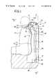
- FIG. 1 is a sectional view showing a chair-type massage machine of the invention
- FIG. 2 is a view in section taken along the line A—A in FIG. 1 and showing the machine as it is seen in the direction of the arrows;
- FIG. 3 is a perspective view of massage units as they are seen from behind
- FIG. 4 is a view in section taken along the line B—B in FIG. 3 and showing the massage unit
- FIG. 5 is a diagram showing the phases of the contact portions of second therapeutic fingers during tapping massage by the second fingers, (a) showing the phase of the contact portions of first therapeutic fingers, (b) showing the phase of the contact portion of the second finger, the plus side of (b) representing the movement of the second finger contact portion toward an affected part pressing direction, the minus side of (b) representing the movement of the same in a direction away from the affected part;
- FIG. 6 is a diagram showing the phases of the contact portions of the first therapeutic fingers during tapping massage by the first fingers, (a) showing the phase of the contact portion of the first therapeutic finger, (b) showing the phase of the contact portion of the second finger, the plus side of (a) representing the movement of the first finger contact portion toward an affected part pressing direction, the minus side of (a) representing the movement of the same in a direction away from the affected part;
- FIG. 7 is a diagram showing the phases of the contact portions of the first and second therapeutic fingers as moved alternately for tapping massage, (a) showing the phase of the contact portion of the first therapeutic finger, (b) showing the phase of the contact portion of the second finger, the plus side of (a) and (b) representing the movement of the contact portion toward an affected part pressing direction, the minus side thereof representing the movement of the same in a direction away from the affected part;
- FIG. 8 is a diagram showing the phases of the contact portions of the first and second therapeutic fingers as moved alternately for finger-pressure massage, (a) showing the phase of the contact portion of the first therapeutic finger, (b) showing the phase of the contact portion of the second finger, the plus side of (a) and (b) representing the movement of the contact portion toward an affected part pressing direction, the minus side thereof representing the movement of the same in a direction away from the affected part;
- FIG. 9 is a diagram showing the phases of the contact portions of the first and second therapeutic fingers as moved simultaneously for tapping massage, (a) showing the phase of the contact portion of the first therapeutic finger, (b) showing the phase of the contact portion of the second finger, the plus side of (a) and (b) representing the movement of the contact portion toward an affected part pressing direction, the minus side thereof representing the movement of the same in a direction away from the affected part;
- FIG. 10 is a view showing a different embodiment of the invention and corresponding to a view in section taken along the line B—B in FIG. 3 of the massage unit;
- FIG. 11 is a diagram showing the massage unit in operation for a somewhat strong massage, with the upper and lower contact portions held in contact;
- FIG. 12 is a diagram showing the massage unit in operation for a soft massage, with the upper and lower contact portions spaced apart;
- FIG. 13 is a perspective view of a conventional massage machine of the chair type.
- front refers to the direction toward which the user 15 sitting in a chair 14 faces, i.e., the direction of arrow F in FIG. 1 .
- a massage machine 12 has the above-mentioned chair 14 which comprises a seat 16 for the user 15 , and a backrest 17 extending upward from the rear end of the seat 16 .
- the backrest 17 is provided with a pair of massage units 10 , 11 which are movable upward and downward and also movable laterally toward and away from each other.
- the backrest 17 of the chair 14 has in its interior a pair of guide rails 20 , 20 extending vertical in parallel to each other and bent in conformity with the back 19 (more specifically, the backbone) of the user 15 .
- the upper end of each guide rail 20 is bent forward so that an upper contact portion 70 of each of the massage units 10 , 11 to be described below will come into contact with the top portion or the top to front portion of the shoulder 18 of the user 15 .
- the guide rail 20 has fitted thereto guide rollers 21 , 21 for guiding the massage unit for upward and downward movement.
- the massage units 10 , 11 are movable upward and downward along the respective guide rails 20 , 20 .
- Endless chains 23 , 23 for moving the respective massage units 10 , 11 are arranged alongside of and to the rear of the respective guide rails 20 , 20 .
- Each chain 23 is in engagement with sprockets 24 , 25 rotatably provided within the backrest 17 respectively at an upper portion and lower portion thereof.
- the chain 23 has a portion connected to a support block 26 , which will be described later, for holding the massage unit.
- a shaft 27 for the lower sprockets 25 is coupled to a chain drive motor 29 by means of a reduction gear mechanism 28 .
- the massage units 10 , 11 are movable upward or downward along the guide rails 20 , 20 by the forward or reverse rotation of the motor 29 .
- the massage units 10 , 11 will be described next.
- the units 10 , 11 are provided at right and left, respectively, so as to massage the right side and left side of the body upper portion of the user 15 .
- These massage units 10 , 11 are movable toward and away from each other as arranged between the support blocks 26 , 26 which are spaced apart by a predetermined distance.
- the guide rollers 21 , 21 fitting in the guide rail 20 are rotatably mounted on the outer side of each support block 26 .
- the chain 23 has one portion fixed to a chain holder 30 projecting from the support block 26 .
- the support blocks 26 , 26 have their bottoms fixed to a holding plate 31 for holding the blocks spaced apart by the predetermined distance. As shown in FIG. 3, two guide bars 33 , 34 and a support rod 35 arranged in parallel have their opposite ends fixed to and supported by the blocks 26 , 26 .
- the two guide bars 33 , 34 are arranged in a horizontal plane.
- the rear guide bar 33 will hereinafter be referred to as the “guide bar for the right,” and the front guide bar 34 as the “guide bar for the left.”
- the support rod 35 is positioned to the front of and above the guide bar 34 for the left.
- the guide bars 33 , 34 for the right and left have slidably fitted thereto a right rack 37 and a left rack 38 , respectively, with their toothed faces opposed to each other.
- a motor 40 for moving the units 10 , 11 toward or away from each other is mounted on the holding plate 31 and has a pinion 41 meshing with teeth of both the racks 37 , 38 at the same time, thereby to provide a drive portion 39 for moving the units 10 , 11 sideways toward and away from each other.
- the motor 40 When driven forward, the motor 40 moves the two racks 37 , 38 toward the center. When rotated reversely, the motor 40 moves the right rack 37 rightward, and the left rack 38 leftward.
- the right rack 37 carries the massage unit 10 for massaging the right side of upper half of the user's body.
- the left rack 38 is provided with the massage unit 11 for massaging the left side of upper half of the body.
- the massage unit 11 for the left side has the same construction as the unit 10 .
- the massage unit 10 for massaging the right side of upper half of the body comprises a casing 43 secured to the right rack 37 , and a pair of upper and lower therapeutic fingers 46 , 48 supported by the casing 43 .
- the casing 43 is secured at its bottom to the right rack 37 .
- the support rod 35 slidably extends through the casing 43 at a front portion thereof.
- each of the therapeutic fingers 46 , 48 comprises a contact portion 70 ( 71 ) in the form of a disk of large thickness for massaging the affected part of the user 15 in contact therewith, and an arm 47 ( 49 ) having the contact portion at its forward end.
- the arms 47 , 49 of the pair of fingers 46 , 48 are positioned one above the other with a specified opening angle formed therebetween and supported by respective pivots 44 , 44 in the casing 43 of the unit 10 so as to be pivotally movable in a vertical plane.
- the forward ends of the arms 47 , 49 project from a front opening of the casing 43 and each have a base end formed with a sector gear 51 which is rotatable about the pivot.
- the casing 43 houses finger drive means 75 , 76 for pivotally moving the respective therapeutic fingers 46 , 48 in a vertical plane.
- two motors 63 , 64 are used as the finger drive means 75 , 76 for individually driving the fingers 46 , 48 independently of each other.
- the drive shafts of the finger drive motors 63 , 64 carry respective worms 65 , 66 which are in mesh with respective worm wheels 67 , 68 supported by the casing 43 with shafts.
- the worm wheel 67 is integral with an intermediate gear A, which is in mesh with the sector gear 51 of the first arm 47 above the other arm.
- the lower worm wheel 68 is integral with an intermediate gear B, which is in mesh with the sector gear 51 of the lower second arm 49 .
- the therapeutic fingers 46 , 48 are pivotally moved about the respective pivots by means of the gears toward or away from each other.
- the left massage unit 11 is similar to the right massage unit 10 in construction and has a casing 43 having its bottom secured to the upper side of the left rack 38 .
- the massage machine 12 of the foregoing construction is adapted to perform various massage operations as shown in FIGS. 5 to 9 by combinations of the forward or reverse rotation of the first finger drive motor 63 and the second finger drive motor 64 , stopping of the motor and the variation of the drive period thereof.
- the massage units 10 , 11 are adjusted in position by driving the chain motor 29 and the motor 40 so that the contact portions 70 of the first fingers 46 each bear on the upper part or the upper to front part of the user's shoulder 18 , with the contact portions of the second fingers 48 positioned for contact with the back 19 of the user 15 .
- FIGS. 5 to 9 show the phase of the contact portion 70 of the first finger 46
- (b) shows the phase of the contact portion 71 of the second finger 48
- zero represents the contact of the contact portion 70 or 71 with the affected part.
- the plus side represents the movement of the contact portion 70 toward a shoulder pressing direction
- the minus side represents the movement of the contact portion 70 in a direction away from the shoulder 18 .
- the plus side represents the movement of the contact portion 71 toward a back pressing direction
- the minus side represents the movement of the contact portion 71 in a direction away from the back 19 .
- FIG. 5 shows the phases of the contact portions 70 , 71 in the case where the back 19 of the user 15 is massaged by tapping with the second finger 48 , with the first finger 46 in contact with the upper part or the upper to front part of the shoulder 18 of the user 15 to prevent the upper part of the user's body from moving upward or forward.
- FIG. 6 shows the phases of the contact portions in the case where the upper part or the upper to front part of the user's shoulder 18 is tapped with first finger 46 for massage, with the second finger 48 in contact with the back 19 of the user 15 to prevent the upper part of the user's body from moving rearward.
- FIG. 7 shows the phases of contact portions 70 , 71 in the case where the shoulder 18 and the back 19 of the user 15 are tapped for massage alternately with the first finger 46 and the second finger 48 .
- the first finger 46 moves out of contact with the shoulder 18
- the second finger 48 taps the back 19 ; conversely, when the second finger 48 leaves the back 19 , the first finger 46 taps the shoulder 18 .
- FIG. 8 shows a case wherein the tapping period of FIG. 7 is lengthened.
- the massage thus given is more similar to finger-pressure massage than the tapping massage of FIG. 7 .
- FIG. 9 shows the phases of the contact portions 70 , 71 in the case where the shoulder 18 and the back 19 of the user 15 are massaged by tapping these parts simultaneously with the first finger 46 and the second finger 48 .
- This operation is shorter in period than the usual kneading massage operation.
- At least two massage operations can be performed alternately using a change-over switch (not shown) or the like.
- a massage may be given with the fingers of the right and left massage units 10 , 11 matched to each other or reversed in movement.
- the massage machine 12 of the chair type is an embodiment of the invention, the invention can of course be embodied as a handy massage device.
- the backrest of the chair-type massage machine has two massage units of the invention as arranged side by side, whereas only one massage unit may be used.
- the upper part of the user's body can be prevented from moving, with the other finger giving an effective tapping massage to the affected part of the user 15 .
- the shoulders 18 of the user 15 can be massaged more effectively if the guide rails 20 , 20 are so bent that the upper part or the upper to front part of the shoulder 18 can be tapped with the contact portion 70 of each first finger 46 .
- This embodiment has the same construction as Embodiment 1 except that the massage units 10 , 11 are different as shown in FIG. 10, and therefore will not be described except the different feature.
- a casing 43 houses one finger drive assembly 45 for pivotally moving two therapeutic fingers 46 , 48 in a vertical plane.
- the drive assembly 45 comprises a finger drive motor 64 .
- the drive shaft of the motor 64 carries a worm 65 which is in mesh with a worm wheel 67 supported by the casing 43 with a shaft.
- the worm wheel 67 is integral with an intermediate gear A, which is in mesh with a sector gear 51 of an upper arm 47 .
- the intermediate gear A is also in mesh with an intermediate gear B supported by the casing 43 with a shaft.
- the intermediate gear B is in mesh with a sector gear 51 of a lower arm 49 .
- the fingers 46 , 48 are pivotally moved, each about its pivot, toward and away from each other by means of the gears.
- the left massage unit 11 has the same construction as the right massage unit 10 .
- the casing 43 of the unit 11 has its bottom secured to the upper side of a left rack 38 .
- the massage machine 12 of the foregoing construction operates in the modes to be described below.
- the finger drive motor 64 of each of the massage units 10 , 11 is driven to bring the upper and lower contact portions 70 , 71 into contact with each other. A strong massage can be given since the pressure to be applied to the user 15 by each massage unit 10 ( 11 ) is concentrated on one spot as seen in FIG. 11 .
- the motor 40 for moving the massage units 10 , 11 toward or away from each other is driven with the direction of rotation changed repeatedly to move the units 10 , 11 toward and away from each other sideways, whereby a somewhat strong massage can be given.
- the upper and lower contact portions 70 , 71 of each of the massage units 10 , 11 are spaced apart by driving the finger drive motor 64 .
- the distance between the contact portions 70 , 71 is determined by the user 15 .
- the pressure to be applied by the massage unit 10 ( 11 ) is dividedly applied to two spots to give a weak or soft massage.
- a soft lateral kneading or back muscle stretching massage can be given by driving the motor 40 or chain drive motor 29 forward and reversely, with the upper and lower contact portions 70 , 71 held spaced apart.
- concentrated pressure can be applied to the affected part of the user 15 for somewhat strong massage, by moving the contact portions 70 , 71 of upper and lower fingers 46 , 48 of the massage units 10 , 11 along the affected part while holding the contact portions 70 , 71 of each unit in contact with each other. Further when the upper and lower contact portions 70 , 71 are spaced apart, the pressure to be applied to the affected part acts dividedly, whereby somewhat weak massage can be given. Whether the contact portions 70 , 71 are to be held in contact or spaced apart can be determined as desired by the user 15 , so that the user 15 can be massaged with the desired intensity.
Abstract
Description
Claims (5)
Priority Applications (1)
| Application Number | Priority Date | Filing Date | Title |
|---|---|---|---|
| US09/635,692 US6511448B1 (en) | 1996-05-27 | 2000-08-10 | Massage machine of chair type |
Applications Claiming Priority (4)
| Application Number | Priority Date | Filing Date | Title |
|---|---|---|---|
| JP13160996A JP3625573B2 (en) | 1996-05-27 | 1996-05-27 | Chair type massage machine |
| JP8-131609 | 1996-05-27 | ||
| JP8-133149 | 1996-05-28 | ||
| JP13314996A JPH09313559A (en) | 1996-05-28 | 1996-05-28 | Massage chair and massage equipment |
Related Child Applications (1)
| Application Number | Title | Priority Date | Filing Date |
|---|---|---|---|
| US09/635,692 Division US6511448B1 (en) | 1996-05-27 | 2000-08-10 | Massage machine of chair type |
Publications (1)
| Publication Number | Publication Date |
|---|---|
| US6200282B1 true US6200282B1 (en) | 2001-03-13 |
Family
ID=26466389
Family Applications (2)
| Application Number | Title | Priority Date | Filing Date |
|---|---|---|---|
| US08/863,070 Expired - Fee Related US6200282B1 (en) | 1996-05-27 | 1997-05-23 | Massage machine of chair type |
| US09/635,692 Expired - Fee Related US6511448B1 (en) | 1996-05-27 | 2000-08-10 | Massage machine of chair type |
Family Applications After (1)
| Application Number | Title | Priority Date | Filing Date |
|---|---|---|---|
| US09/635,692 Expired - Fee Related US6511448B1 (en) | 1996-05-27 | 2000-08-10 | Massage machine of chair type |
Country Status (8)
| Country | Link |
|---|---|
| US (2) | US6200282B1 (en) |
| EP (1) | EP0809993B1 (en) |
| KR (1) | KR100231146B1 (en) |
| CN (1) | CN1173682C (en) |
| AT (1) | ATE238019T1 (en) |
| DE (1) | DE69721125T2 (en) |
| ES (1) | ES2192633T3 (en) |
| TW (1) | TW364846B (en) |
Cited By (33)
| Publication number | Priority date | Publication date | Assignee | Title |
|---|---|---|---|---|
| US6440091B1 (en) * | 1999-09-17 | 2002-08-27 | Matoba Electric Manufacturing Co., Ltd. | Compact massage machine |
| US6443917B1 (en) * | 1997-06-17 | 2002-09-03 | Eurokeyton, S. A. | Massaging device for a rest armchair |
| US6494851B1 (en) * | 2000-04-19 | 2002-12-17 | James Becher | Real time, dry mechanical relaxation station and physical therapy device simulating human application of massage and wet hydrotherapy |
| US6511448B1 (en) * | 1996-05-27 | 2003-01-28 | Sanyo Electric Co., Ltd. | Massage machine of chair type |
| US6517500B2 (en) * | 1999-12-20 | 2003-02-11 | Toshiba Tech Kabushiki Kaisha | Massager having treatment members adapted to be moved in an arc shape |
| US6540701B1 (en) * | 1999-01-11 | 2003-04-01 | Family Kabushiki Kaisha | Massaging machine |
| US6585668B2 (en) * | 1999-12-16 | 2003-07-01 | Elias Nissim | Human touch massager |
| US6607499B1 (en) * | 2000-04-19 | 2003-08-19 | James Becher | Portable real time, dry mechanical relaxation and physical therapy device simulating application of massage and wet hydrotherapy for limbs |
| WO2004017891A1 (en) * | 2002-08-26 | 2004-03-04 | Syung Hyun Cho | Thermal rolling device for thermotherapy systems |
| US20040082889A1 (en) * | 2002-10-23 | 2004-04-29 | Dong-Her Wu | Cervical vertebra massaging device with roller sets |
| US6840914B1 (en) * | 1999-07-29 | 2005-01-11 | Shigeo Takamura | Electrically powered roller massaging implement |
| US20050245851A1 (en) * | 2004-04-30 | 2005-11-03 | Roman Ferber | Portable body massager |
| US20060155223A1 (en) * | 2002-05-10 | 2006-07-13 | Dietmar Koch | Piece of furniture comprising a massage unit |
| US20070060851A1 (en) * | 2005-09-09 | 2007-03-15 | Roman Ferber | Body massager with illumination effects |
| US20070106185A1 (en) * | 2004-04-30 | 2007-05-10 | Roman Ferber | Portable body massager |
| US20070208284A1 (en) * | 2006-03-01 | 2007-09-06 | Huang Chien M | Body massage apparatus |
| US20070299379A1 (en) * | 2004-05-11 | 2007-12-27 | Xiuqun Luo | Massage Device |
| WO2008112488A2 (en) * | 2007-03-09 | 2008-09-18 | Fka Distributing Co. D/B/A Homedics, Inc. | Body massager |
| US7470242B2 (en) | 2005-03-18 | 2008-12-30 | Fka Distributing Co. | Portable body massager having width adjustable massage members on translating carriage |
| US20090149785A1 (en) * | 2005-08-26 | 2009-06-11 | Enrique Canto Garcia | Massage device |
| US20120271205A1 (en) * | 2011-04-18 | 2012-10-25 | Kiremitci Kirkor | Photo light therapy and massaging apparatus |
| US20140207035A1 (en) * | 2013-01-22 | 2014-07-24 | Donnie Zimmerman | Myofascial release apparatus and method |
| US9409035B2 (en) | 2011-04-18 | 2016-08-09 | Kirkor KIREMITCI | Oscillating photo light therapy device |
| US9655813B2 (en) | 2010-12-14 | 2017-05-23 | Kkt International Ltd. | Stylus and treatment head for use with a medical device |
| US20170258669A1 (en) * | 2015-06-24 | 2017-09-14 | Daito Electric Machine Industry Company Limited | Massage mechanism and legless chair-type massage machine including this massage mechanism |
| US20180243153A1 (en) * | 2017-02-24 | 2018-08-30 | The Regents of the University of Michigan, Univers ity of Michigan Office of Technology Transfer | Multiple Actuator Vibration Therapy |
| US20190151187A1 (en) * | 2017-06-02 | 2019-05-23 | Family Inada Co., Ltd. | Massage machine |
| US10610442B2 (en) * | 2014-02-27 | 2020-04-07 | Daito Electric Machine Industry Company Limited | Massage device |
| CN111067772A (en) * | 2019-12-31 | 2020-04-28 | 温州医科大学附属第二医院、温州医科大学附属育英儿童医院 | Lumbar vertebra massager integrating kneading, pushing and discharging functions and massaging method thereof |
| US20200375842A1 (en) * | 2018-02-19 | 2020-12-03 | Bodyfriend Co., Ltd. | Massage module and massage device comprising same |
| CN112641618A (en) * | 2020-12-20 | 2021-04-13 | 永康市泰琪健身器材有限公司 | Multi-drive multi-head fascia gun |
| CN113499234A (en) * | 2021-08-19 | 2021-10-15 | 和也健康科技有限公司 | Far infrared stone needle fiber magnetic therapy massage chair |
| US11865060B2 (en) * | 2018-01-31 | 2024-01-09 | Family Inada Co., Ltd. | Treatment unit and massage machine |
Families Citing this family (34)
| Publication number | Priority date | Publication date | Assignee | Title |
|---|---|---|---|---|
| JP4020581B2 (en) * | 2000-11-15 | 2007-12-12 | 三洋電機株式会社 | Chair type massage machine |
| DE10109849A1 (en) * | 2001-03-01 | 2002-09-12 | Tinnitus Signal Medizin Gmbh | Comfortable head support for use in treatment of patients in the head region, particularly treatment of tinnitus where the head must be held in a constant position for periods of about an hour |
| KR20020089883A (en) * | 2001-05-25 | 2002-11-30 | 주식회사 지인텍 | Massage device |
| KR20020091566A (en) * | 2001-05-31 | 2002-12-06 | 주식회사 지인텍 | Massage device |
| KR20020091564A (en) * | 2001-05-31 | 2002-12-06 | 주식회사 지인텍 | Massage device |
| US20030233060A1 (en) * | 2002-06-18 | 2003-12-18 | He-Chun Liu | Automatic massage device |
| US6837861B2 (en) * | 2002-09-09 | 2005-01-04 | Cheng-Hsien Lin | Electric massage device for producing rotational or reciprocating massage motion |
| US20040106882A1 (en) * | 2002-11-29 | 2004-06-03 | Chin-Chun Tseng | Kneading massage structure |
| US7029453B2 (en) * | 2003-07-09 | 2006-04-18 | Ko-Po Chen | Massaging mechanism of massaging machine |
| US7083582B2 (en) * | 2003-10-22 | 2006-08-01 | Ko-Po Chen | Massaging mechanism of massaging machine |
| JP4046702B2 (en) * | 2004-02-26 | 2008-02-13 | 三洋電機株式会社 | Massage unit and chair type massage machine provided with the unit |
| US8123708B2 (en) | 2004-05-11 | 2012-02-28 | Weightec Electronic Technology Co., Ltd. | Massage device |
| CN201147462Y (en) | 2008-01-15 | 2008-11-12 | 东莞威德电子科技有限公司 | Vibration massage device |
| US8414510B2 (en) | 2004-05-11 | 2013-04-09 | Chichun Wu | Massage device with a massage head distance adjusting mechanism |
| US7354409B2 (en) * | 2004-10-21 | 2008-04-08 | Horatiu Mircea Popescu | Adjustable massage system of seat type |
| CN1989921B (en) * | 2005-12-29 | 2010-05-12 | 财团法人工业技术研究院 | Chair back massage apparatus and setting, front pulling, rubbing and hammering mechanism thereof |
| US20080071201A1 (en) * | 2006-09-15 | 2008-03-20 | Horatiu Mircea Popescu | Simplified massage system of seat type |
| US20080161736A1 (en) * | 2006-12-28 | 2008-07-03 | Richard Leifer | Massage device of chair type |
| KR100966084B1 (en) * | 2008-02-25 | 2010-06-28 | 한정민 | The remedy apparatus for the cervical vertebrae |
| KR200456153Y1 (en) | 2008-11-12 | 2011-10-17 | (주)대경산업 | Massage chair having independently controllable massagers |
| CN101856298B (en) * | 2009-04-10 | 2011-08-17 | 中国科学院沈阳自动化研究所 | Massage head with variable structure |
| EP2272484A1 (en) * | 2009-07-10 | 2011-01-12 | Chichun Wu | Massage device with massage head distance adjusting mechanism |
| CN103301011B (en) * | 2013-06-04 | 2016-03-30 | 南京林业大学 | A kind of multipoint removable type multifunctional massage lab chair |
| US10849819B2 (en) | 2013-12-11 | 2020-12-01 | Luraco, Inc. | System and method for body stretching by massage chair |
| US10092480B2 (en) | 2013-12-11 | 2018-10-09 | Luraco, Inc. | Touchscreen-based control system for massage chairs |
| CN106102684B (en) * | 2014-02-27 | 2018-10-23 | 傲胜国际有限公司 | Massage armchair and its driving method |
| DE102016211718A1 (en) * | 2016-06-29 | 2018-01-04 | Brose Fahrzeugteile Gmbh & Co. Kommanditgesellschaft, Coburg | Method for controlling motors of a massage device, control device and seat arrangement provided in a seat, in particular a vehicle seat |
| US10842708B2 (en) | 2017-01-25 | 2020-11-24 | Luraco, Inc. | Massage apparatus for legs and feet and massage chair having the massage apparatus |
| US11179290B2 (en) | 2017-05-11 | 2021-11-23 | Luraco, Inc. | Massage chair having a wireless charger, armrest sliding, hammering devices, and oxygen generation |
| US10724549B2 (en) | 2017-05-11 | 2020-07-28 | Luraco, Inc. | Massage chair having a noise-reducing, enclosure device |
| CN107648030B (en) * | 2017-11-06 | 2020-05-12 | 郑招才 | Massage chair capable of relieving shoulder and neck fatigue |
| CN109248063A (en) * | 2017-11-21 | 2019-01-22 | 厦门蒙发利电子有限公司 | A kind of massager core and massager |
| US10639230B2 (en) | 2018-04-29 | 2020-05-05 | Luraco, Inc. | Massage chair having a mechanism for adjusting position of fluid massage element for arm massaging |
| US10891000B2 (en) | 2019-01-24 | 2021-01-12 | Kevin Le | Massage chairs with touchscreen-based control system |
Citations (7)
| Publication number | Priority date | Publication date | Assignee | Title |
|---|---|---|---|---|
| US4009710A (en) | 1974-07-11 | 1977-03-01 | Nichimu Inada | Electromassager |
| DE3712085A1 (en) | 1986-04-11 | 1987-10-15 | Family K K | Electronically open-loop and/or closed-loop controlled massaging device |
| US4899403A (en) * | 1989-03-03 | 1990-02-13 | Kabushiki Kaisha Fuji Iryoki | Apparatus for controlling expansion or contraction of cover cloth with respect to bed base |
| US5020518A (en) * | 1990-02-09 | 1991-06-04 | Integrity Health Systems Corporation | Travelling roller massage apparatus |
| DE9419742U1 (en) | 1994-12-09 | 1995-02-02 | Kuang Yu Metal Working Co | Massage chair |
| US5460598A (en) * | 1993-10-22 | 1995-10-24 | Kabushiki Kaisha Japan Health | Polyfunctional automatic massager of chair type |
| US5462516A (en) * | 1993-12-29 | 1995-10-31 | Niagara Therapy Manufacturing, Inc. | Cyclical action massaging chair |
Family Cites Families (4)
| Publication number | Priority date | Publication date | Assignee | Title |
|---|---|---|---|---|
| US3709047A (en) * | 1971-01-21 | 1973-01-09 | Textol Syst Inc | Linear actuator system with reversing means |
| US3736920A (en) * | 1971-03-18 | 1973-06-05 | Niagara Therapy Manuf Corp | Traveling massager assembly |
| JPH0759825A (en) * | 1993-08-26 | 1995-03-07 | Matsushita Electric Works Ltd | Massage machine |
| TW364846B (en) * | 1996-05-27 | 1999-07-21 | Sanyo Electric Co | Chair type massage machine |
-
1997
- 1997-05-01 TW TW086105785A patent/TW364846B/en not_active IP Right Cessation
- 1997-05-23 DE DE69721125T patent/DE69721125T2/en not_active Expired - Fee Related
- 1997-05-23 ES ES97108402T patent/ES2192633T3/en not_active Expired - Lifetime
- 1997-05-23 US US08/863,070 patent/US6200282B1/en not_active Expired - Fee Related
- 1997-05-23 AT AT97108402T patent/ATE238019T1/en not_active IP Right Cessation
- 1997-05-23 EP EP97108402A patent/EP0809993B1/en not_active Expired - Lifetime
- 1997-05-26 KR KR1019970020664A patent/KR100231146B1/en not_active IP Right Cessation
- 1997-05-27 CN CNB971149682A patent/CN1173682C/en not_active Expired - Fee Related
-
2000
- 2000-08-10 US US09/635,692 patent/US6511448B1/en not_active Expired - Fee Related
Patent Citations (7)
| Publication number | Priority date | Publication date | Assignee | Title |
|---|---|---|---|---|
| US4009710A (en) | 1974-07-11 | 1977-03-01 | Nichimu Inada | Electromassager |
| DE3712085A1 (en) | 1986-04-11 | 1987-10-15 | Family K K | Electronically open-loop and/or closed-loop controlled massaging device |
| US4899403A (en) * | 1989-03-03 | 1990-02-13 | Kabushiki Kaisha Fuji Iryoki | Apparatus for controlling expansion or contraction of cover cloth with respect to bed base |
| US5020518A (en) * | 1990-02-09 | 1991-06-04 | Integrity Health Systems Corporation | Travelling roller massage apparatus |
| US5460598A (en) * | 1993-10-22 | 1995-10-24 | Kabushiki Kaisha Japan Health | Polyfunctional automatic massager of chair type |
| US5462516A (en) * | 1993-12-29 | 1995-10-31 | Niagara Therapy Manufacturing, Inc. | Cyclical action massaging chair |
| DE9419742U1 (en) | 1994-12-09 | 1995-02-02 | Kuang Yu Metal Working Co | Massage chair |
Cited By (51)
| Publication number | Priority date | Publication date | Assignee | Title |
|---|---|---|---|---|
| US6511448B1 (en) * | 1996-05-27 | 2003-01-28 | Sanyo Electric Co., Ltd. | Massage machine of chair type |
| US6443917B1 (en) * | 1997-06-17 | 2002-09-03 | Eurokeyton, S. A. | Massaging device for a rest armchair |
| US6540701B1 (en) * | 1999-01-11 | 2003-04-01 | Family Kabushiki Kaisha | Massaging machine |
| US6840914B1 (en) * | 1999-07-29 | 2005-01-11 | Shigeo Takamura | Electrically powered roller massaging implement |
| US6440091B1 (en) * | 1999-09-17 | 2002-08-27 | Matoba Electric Manufacturing Co., Ltd. | Compact massage machine |
| US6585668B2 (en) * | 1999-12-16 | 2003-07-01 | Elias Nissim | Human touch massager |
| US6517500B2 (en) * | 1999-12-20 | 2003-02-11 | Toshiba Tech Kabushiki Kaisha | Massager having treatment members adapted to be moved in an arc shape |
| US6607499B1 (en) * | 2000-04-19 | 2003-08-19 | James Becher | Portable real time, dry mechanical relaxation and physical therapy device simulating application of massage and wet hydrotherapy for limbs |
| US6494851B1 (en) * | 2000-04-19 | 2002-12-17 | James Becher | Real time, dry mechanical relaxation station and physical therapy device simulating human application of massage and wet hydrotherapy |
| US20070027413A9 (en) * | 2002-05-10 | 2007-02-01 | Dietmar Koch | Piece of furniture comprising a massage unit |
| US20060155223A1 (en) * | 2002-05-10 | 2006-07-13 | Dietmar Koch | Piece of furniture comprising a massage unit |
| WO2004017891A1 (en) * | 2002-08-26 | 2004-03-04 | Syung Hyun Cho | Thermal rolling device for thermotherapy systems |
| US20040082889A1 (en) * | 2002-10-23 | 2004-04-29 | Dong-Her Wu | Cervical vertebra massaging device with roller sets |
| US6899688B2 (en) * | 2002-10-23 | 2005-05-31 | Dong-Her Wu | Cervical vertebra massaging device with roller sets |
| US20050245851A1 (en) * | 2004-04-30 | 2005-11-03 | Roman Ferber | Portable body massager |
| US7128721B2 (en) | 2004-04-30 | 2006-10-31 | Homedics, Inc. | Portable body massager |
| US20070106185A1 (en) * | 2004-04-30 | 2007-05-10 | Roman Ferber | Portable body massager |
| US20070299379A1 (en) * | 2004-05-11 | 2007-12-27 | Xiuqun Luo | Massage Device |
| US7731672B2 (en) * | 2004-05-11 | 2010-06-08 | Chichun Wu | Massage device |
| US11684539B2 (en) | 2005-03-18 | 2023-06-27 | Fka Distributing Co., Llc | Portable body massager |
| US10413472B2 (en) | 2005-03-18 | 2019-09-17 | FKS Distibuting Co. | Portable body massager |
| US20090093742A1 (en) * | 2005-03-18 | 2009-04-09 | Fka Distributing Co. D/B/A Homedics, Inc. | Portable body massager |
| US7470242B2 (en) | 2005-03-18 | 2008-12-30 | Fka Distributing Co. | Portable body massager having width adjustable massage members on translating carriage |
| US20090149785A1 (en) * | 2005-08-26 | 2009-06-11 | Enrique Canto Garcia | Massage device |
| US20080306416A1 (en) * | 2005-09-09 | 2008-12-11 | Fka Distributing Co. D/B/A Homedics, Inc. | Body massager with illumination effects |
| US7419475B2 (en) | 2005-09-09 | 2008-09-02 | Fka Distibuting Co. | Body massager with illumination effects |
| US8147435B2 (en) | 2005-09-09 | 2012-04-03 | Fka Distributing Co. | Body massager with illumination effects |
| US20070060851A1 (en) * | 2005-09-09 | 2007-03-15 | Roman Ferber | Body massager with illumination effects |
| US7597669B2 (en) | 2006-03-01 | 2009-10-06 | Fka Distributing Co. | Body massage apparatus |
| US20070208284A1 (en) * | 2006-03-01 | 2007-09-06 | Huang Chien M | Body massage apparatus |
| US20080262398A1 (en) * | 2007-03-09 | 2008-10-23 | Fka Distributing Co. D/B/A Homedics, Inc. | Body massager |
| WO2008112488A2 (en) * | 2007-03-09 | 2008-09-18 | Fka Distributing Co. D/B/A Homedics, Inc. | Body massager |
| US8394041B2 (en) | 2007-03-09 | 2013-03-12 | Fka Distributing Co., Llc | Body massager |
| WO2008112488A3 (en) * | 2007-03-09 | 2008-11-06 | Fka Distributing Dba Homedics | Body massager |
| US9655813B2 (en) | 2010-12-14 | 2017-05-23 | Kkt International Ltd. | Stylus and treatment head for use with a medical device |
| US20120271205A1 (en) * | 2011-04-18 | 2012-10-25 | Kiremitci Kirkor | Photo light therapy and massaging apparatus |
| US9409035B2 (en) | 2011-04-18 | 2016-08-09 | Kirkor KIREMITCI | Oscillating photo light therapy device |
| US9339435B2 (en) * | 2011-04-18 | 2016-05-17 | Kirkor KIREMITCI | Photo light therapy and massaging apparatus |
| US20140207035A1 (en) * | 2013-01-22 | 2014-07-24 | Donnie Zimmerman | Myofascial release apparatus and method |
| US10610442B2 (en) * | 2014-02-27 | 2020-04-07 | Daito Electric Machine Industry Company Limited | Massage device |
| US20170258669A1 (en) * | 2015-06-24 | 2017-09-14 | Daito Electric Machine Industry Company Limited | Massage mechanism and legless chair-type massage machine including this massage mechanism |
| US11491069B2 (en) * | 2017-02-24 | 2022-11-08 | The Regents Of The University Of Michigan | Multiple actuator vibration therapy |
| US20180243153A1 (en) * | 2017-02-24 | 2018-08-30 | The Regents of the University of Michigan, Univers ity of Michigan Office of Technology Transfer | Multiple Actuator Vibration Therapy |
| US20190151187A1 (en) * | 2017-06-02 | 2019-05-23 | Family Inada Co., Ltd. | Massage machine |
| US11701291B2 (en) * | 2017-06-02 | 2023-07-18 | Family Inada Co., Ltd. | Massage machine |
| US11865060B2 (en) * | 2018-01-31 | 2024-01-09 | Family Inada Co., Ltd. | Treatment unit and massage machine |
| US20200375842A1 (en) * | 2018-02-19 | 2020-12-03 | Bodyfriend Co., Ltd. | Massage module and massage device comprising same |
| CN111067772A (en) * | 2019-12-31 | 2020-04-28 | 温州医科大学附属第二医院、温州医科大学附属育英儿童医院 | Lumbar vertebra massager integrating kneading, pushing and discharging functions and massaging method thereof |
| CN112641618A (en) * | 2020-12-20 | 2021-04-13 | 永康市泰琪健身器材有限公司 | Multi-drive multi-head fascia gun |
| CN113499234A (en) * | 2021-08-19 | 2021-10-15 | 和也健康科技有限公司 | Far infrared stone needle fiber magnetic therapy massage chair |
| CN113499234B (en) * | 2021-08-19 | 2024-01-02 | 和也健康科技有限公司 | Far infrared stone needle fiber magnetic therapy massage chair |
Also Published As
| Publication number | Publication date |
|---|---|
| EP0809993B1 (en) | 2003-04-23 |
| US6511448B1 (en) | 2003-01-28 |
| CN1170568A (en) | 1998-01-21 |
| DE69721125D1 (en) | 2003-05-28 |
| KR100231146B1 (en) | 2000-02-01 |
| EP0809993A3 (en) | 1999-01-27 |
| TW364846B (en) | 1999-07-21 |
| EP0809993A2 (en) | 1997-12-03 |
| ES2192633T3 (en) | 2003-10-16 |
| CN1173682C (en) | 2004-11-03 |
| DE69721125T2 (en) | 2004-02-19 |
| ATE238019T1 (en) | 2003-05-15 |
| KR970073548A (en) | 1997-12-10 |
Similar Documents
| Publication | Publication Date | Title |
|---|---|---|
| US6200282B1 (en) | Massage machine of chair type | |
| JP3113057U (en) | Massage device | |
| US20090093742A1 (en) | Portable body massager | |
| JP2000225160A (en) | Chair massager with long guide rail | |
| JPH09262264A (en) | Massage machine | |
| US4173972A (en) | Massaging machine | |
| JP2004242707A (en) | Massage machine | |
| JP3485722B2 (en) | Massage machine treatment finger | |
| JPH09313560A (en) | Massaging device and chair type massaging machine | |
| JP3625573B2 (en) | Chair type massage machine | |
| JP3490837B2 (en) | Massage machine | |
| JP7121998B2 (en) | chair massage machine | |
| JPH09313559A (en) | Massage chair and massage equipment | |
| JPH09262263A (en) | Massage chair | |
| JP3625574B2 (en) | Chair type massage machine | |
| JP3338141B2 (en) | Massage machine | |
| JPH11244348A (en) | Massage machine | |
| JP3490836B2 (en) | Massage machine | |
| JP2020048732A (en) | Sole massage machine and chair type massage machine equipped with the same | |
| JP4507702B2 (en) | Massage machine | |
| JP4419683B2 (en) | Massage machine | |
| JP3485723B2 (en) | Massage equipment | |
| JP2008136575A (en) | Massage machine | |
| JP2004242708A (en) | Massage machine | |
| JPH09299431A (en) | Finger for therapy of massaging apparatus |
Legal Events
| Date | Code | Title | Description |
|---|---|---|---|
| AS | Assignment |
Owner name: SANYO ELECTRIC CO., LTD., JAPAN Free format text: ASSIGNMENT OF ASSIGNORS INTEREST;ASSIGNORS:FURUIE, YOSHIYA;TANIMOTO, YOSHIHIRO;REEL/FRAME:011121/0484 Effective date: 19970514 Owner name: SANYO ELECTRIC CO., LTD., JAPAN Free format text: ASSIGNMENT OF ASSIGNORS INTEREST;ASSIGNORS:FURUIE, YOSHIYA;TANIMOTO, YOSHIHIRO;REEL/FRAME:008584/0014 Effective date: 19970514 |
|
| FPAY | Fee payment |
Year of fee payment: 4 |
|
| REMI | Maintenance fee reminder mailed | ||
| LAPS | Lapse for failure to pay maintenance fees | ||
| STCH | Information on status: patent discontinuation |
Free format text: PATENT EXPIRED DUE TO NONPAYMENT OF MAINTENANCE FEES UNDER 37 CFR 1.362 |
|
| FP | Lapsed due to failure to pay maintenance fee |
Effective date: 20090313 |