US6202170B1 - Equipment protection system - Google Patents
Equipment protection system Download PDFInfo
- Publication number
- US6202170B1 US6202170B1 US09/121,148 US12114898A US6202170B1 US 6202170 B1 US6202170 B1 US 6202170B1 US 12114898 A US12114898 A US 12114898A US 6202170 B1 US6202170 B1 US 6202170B1
- Authority
- US
- United States
- Prior art keywords
- function
- server
- active
- client
- standby
- Prior art date
- Legal status (The legal status is an assumption and is not a legal conclusion. Google has not performed a legal analysis and makes no representation as to the accuracy of the status listed.)
- Expired - Lifetime
Links
Images


Classifications
-
- H—ELECTRICITY
- H04—ELECTRIC COMMUNICATION TECHNIQUE
- H04Q—SELECTING
- H04Q1/00—Details of selecting apparatus or arrangements
- H04Q1/18—Electrical details
- H04Q1/20—Testing circuits or apparatus; Circuits or apparatus for detecting, indicating, or signalling faults or troubles
- H04Q1/22—Automatic arrangements
- H04Q1/24—Automatic arrangements for connection devices
-
- H—ELECTRICITY
- H04—ELECTRIC COMMUNICATION TECHNIQUE
- H04L—TRANSMISSION OF DIGITAL INFORMATION, e.g. TELEGRAPHIC COMMUNICATION
- H04L49/00—Packet switching elements
- H04L49/55—Prevention, detection or correction of errors
- H04L49/557—Error correction, e.g. fault recovery or fault tolerance
-
- H—ELECTRICITY
- H04—ELECTRIC COMMUNICATION TECHNIQUE
- H04M—TELEPHONIC COMMUNICATION
- H04M3/00—Automatic or semi-automatic exchanges
- H04M3/18—Automatic or semi-automatic exchanges with means for reducing interference or noise; with means for reducing effects due to line faults with means for protecting lines
Definitions
- the present invention relates to the design of computer systems, and, in particular, to computer system architectures that provide automatic protection switching from active functions to standby functions to maintain uninterrupted system operations.
- a switch node in a telecommunication system may be responsible for receiving, routing, and re-transmitting a large number of signals to support telecommunications between many pairs of end users of the system.
- the switch node may consist of a number of circuit boards operating together to support the overall signal switching operations of the node.
- FIG. 1 shows a block diagram of a switch node 100 for a telecommunication system.
- Switch node 100 comprises working switch function 102 connected to a plurality of working port functions 104 .
- Each working port function 104 provides the interface between working switch function 102 and the rest of the telecommunication system for a particular subset of the signals that are routed by working switch function 102 .
- each working switch and port function may be implemented on a separate circuit board.
- switch node 100 In order to maintain uninterrupted telecommunication services to the various end users, it is desirable to provide a hardware design that enables switch node 100 to continue to operate even if one of the working circuit boards fails or otherwise begins to operate in a degraded manner. This may be achieved by providing an additional switch circuit board as a protection (i.e., backup) switch function and an additional port circuit board as a protection port function. If working switch function 102 fails, the protection switch function can assume its switch operations. Likewise, if any one of the working port functions 104 fails, the protection port function can assume its port operations. Such schemes are referred to as protection switching, where a protection function is switched on-line to assume the responsibilities of a failed working function.
- the word “switching” in the term “protection switching” refers to the switching of functions and is not related to the switching of signals provided by the switch functions in the telecommunication example of FIG. 1 .
- FIG. 2 shows a block diagram of a generic system 200 that provides protection switching in the event of function failure.
- a working server function 202 communicates with client function 206 to support system operations.
- System 200 also has a protection server function 204 , identical to working server function 202 , as a backup in case working server function 202 fails to continue to operate properly.
- Protection server function 204 may be inactive (i.e., cold standby) or it may be operating off-line (i.e., hot standby).
- control function 208 which monitors the operations of both working and protection server functions 202 and 204 for failures.
- working server function 202 of FIG. 2 may be a working switch function
- protection server function 204 may be a protection switch function
- client function 206 may be one of the port functions.
- FIG. 2 corresponds to protection switching provided for working switch function 102 in FIG. 1 .
- Analogous protection switching may also be provided for working port functions 104 .
- control function 208 activates protection server function 204 , if necessary (e.g., if protection server function 204 was in a cold standby mode), and directly instructs client function 206 via communication link 210 to switch its selection of which server function is active from working server function 202 to protection server function 204 .
- control function 208 To maintain knowledge of client function 206 and to communicate directly with client function 206 .
- control function 208 must maintain knowledge of a large number of client functions. Whenever the configuration of the client functions changes (e.g., a client function is added or deleted from the system), the database of information in control function 208 must be updated. In addition, unless the client functions are designed to transmit acknowledgment messages back to control function 208 , control function 208 is never sure whether all of the client functions will have received its instructions.
- control function 208 would not know that the client function had not received the instructions, and, when the client function is brought back on-line, it will assume that the failed working server function 202 is still the active server function.
- the requirement for control function 208 to communicate directly with each client function may cause a relatively long delay after a server function failure before all of the client functions can be instructed to switch to protection server function 204 , which can result in an interruption of the overall system operations. For example, in a telecommunication system, under such circumstances, signals between one or more—and possibly all—pairs of end users may be dropped.
- control function 208 if control function 208 detects a failure in working server function 202 , the control function 208 informs only server functions 202 and 204 of the need to switch from working server function 202 to protection server function 204 .
- Server functions 202 and 204 notify the client functions of the need to switch to protection server function 204 .
- This is typically implemented by each server function using in-band signaling in which a specific status bit in the overhead data communicated to each client function identifies whether or not the server function is active.
- Each client function monitors that status bit from each server function to determine whether to continue to operate with working server function 202 or to switch to protection server function 204 .
- the present invention is directed to an equipment protection scheme that addresses certain situations that were not covered by prior art equipment protection schemes.
- the present invention is a protection switching system, comprising (a) a client function; (b) a working server function, configured to communicate with the client function; (c) a protection server function, configured to communicate with the client function; and (d) a control function, configured to monitor the health of the working and protection server functions for failures and to implement protection switching from the working server function to the protection server function.
- Each of the working and protection server functions is configured to transmit to the client function (1) a status condition indicating whether the server function is active or standby and (2) an override condition.
- the client function is configured to monitor the health of the working and protection server functions and to implement protection switching from the working server function to the protection server function based on the health, the status condition, and the override condition for each of the working and protection server functions.
- the present invention provides advantages over schemes that require the control function to notify each client function directly of a server failure. For example, the control function does not have to be aware of configuration changes made to the client functions. Furthermore, by allowing client functions to implement autonomous protection switching, protection switching can be implemented faster and more efficiently.
- the present invention handles race conditions and other ambiguous situations that were not addressed by previous schemes.
- the use of the additional override condition enables the control function to override normal client protection switch processing, for example, to implement forced protection switches.
- FIG. 1 shows a block diagram of a switch node for a telecommunication system
- FIG. 2 shows a block diagram of a generic system that provides protection switching in the event of function failure
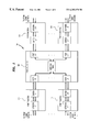
- FIG. 3 shows a protection switching system, according to one embodiment of the present invention, in which 1+1 protection is implemented
- FIG. 4 shows a protection switching system, according to one embodiment of the present invention, in which each server function is implemented on two circuit boards;
- FIG. 5 shows a protection switching system, according to one embodiment of the present invention, in which duplicated circuit boards form two protection planes;
- FIG. 6 shows a protection switching system, according to one embodiment of the present invention, in which 1+1 protection is implemented using distributed connectors;
- FIG. 7 shows a protection switching system, according to one embodiment of the present invention, in which 1+n protection is implemented.
- FIG. 8 shows the protection switching mechanism for the system of FIG. 7, according to one embodiment of the present invention.
- the present invention is directed to protection switching systems that implement an equipment protection scheme.
- protection means that, for a certain function in a system, redundancy is provided so that failure of an active function will not lead to loss of the functionality, since the function can be taken over by a backup function.
- Equipment protection refers to the protection of functions within a network element or node, where a function may refer to hardware or a combination of hardware and software.
- active refers to a function that is providing service
- standby refers to a function that is not yet providing service.
- Standby functions may operate in two different modes: hot standby and cold standby.
- Hot standby refers to a function that is fully functional and acts in synchronism with an active function.
- a function in hot standby mode is able to take over the role of the active function immediately without need for initialization.
- Cold standby refers to a function that is not acting in synchronism with an active function.
- a function in cold standby mode is not able to take over the role of the active function immediately; rather, it needs some form of initialization and/or provisioning before it can do so.
- Active and standby are dynamic connotations. An active function can become standby, and vice versa. Nevertheless, it is general usage to label functions statically, e.g., based on their physical locations.
- protection switching systems There are different types of protection switching systems. In 1+1 protection, one active function is protected by a single standby function. In 1:n protection, n active functions are protected by a single standby function. In m:n protection, n active functions are protected by m standby functions, where m:n protection is a straightforward extension of 1:n protection.
- a working function is one that, if present and healthy, will become active at power up, while a protection function is one that will become standby at power up.
- the distinction between working and protection is not essential in the case of 1+1 protection, although it is common to have a default active function at power up.
- interface selectors may be implemented such that the single protection function can be distinguished from the n working functions.
- working and protection are static connotations, while active and standby are dynamic connotations.
- each working function is active and any protection functions are standby. After protection switching occurs, a (e.g., failed) working function will be standby and a protection function will be active.
- An interface selector is an entity that is used to select between the signals from the working and protection functions. There are different ways to implement interface selectors. For example, a centralized interface selector is a single switch, where a selection is made between the signals at the input of the selector. A distributed interface selector, on the other hand, refers to multiple switches, where specific combinations of settings result in the selection of the designed input signal.
- FIG. 3 shows protection switching system 300 , according to one embodiment of the present invention, in which 1+1 protection is implemented.
- System 300 comprises working server function 302 , protection server function 304 , client function 306 , and control function 308 .
- working server function 302 operates with client function 306
- control function 308 monitors working server function 302 for failures
- protection server function 304 provides redundancy in case working server function 302 fails or otherwise becomes degraded.
- client function 306 is represented in FIG. 3, it should be understood that there may be a plurality of such client functions, each of which is capable of operating with either working server function 302 or protection server function 304 .
- Protection switching processing for system 300 is typically implemented as a finite state machine.
- the solid lines represent actual physical communication links, while the broken lines represent virtual communication links. Actual communication links exist between control function 308 and each server function 302 and 304 , and between each server function 302 and 304 and client function 306 .
- Equipment failure on the active server function e.g., error detected in an ASIC, FPGA, on-board memory, or in controller complex.
- Interface failure error detected on one of the internal interfaces to or from the active server function.
- the set of possible interface failures depends on the nature of the interface (e.g., transmission, control, timing, power). Examples include loss of signal, loss of clock, loss of frame, and trace identifier mismatch.
- Interface degradation e.g., parity or cyclic redundancy check (CRC) errors detected on the interface.
- CRC cyclic redundancy check
- the term “failed” refers to a condition where the signal is absent or corrupted to such an extent that the contents of the signal are sufficiently unreliable
- the term “degraded” refers to a condition where there are errors in the signal, but the contents of the signal are still reasonably accurate.
- An example of a degraded signal may be one in which every tenth frame has a parity error. In that case, a client function may still be able to determine overhead information from the other nine frames.
- a forced protection switch will be executed even if the standby server function is degraded, while a manual protection switch will not be executed if the standby server function is degraded.
- the following signals are of importance to the protection switching finite state machine:
- Lockout a command to inhibit all automatic protection switching.
- the lockout condition can be enabled (i.e., set to 1 or true) or disabled (i.e., set to 0 or false) by reception of an externally generated command, but also by an autonomous action within the network element.
- a clear request can be considered to be a form of forced switch request.
- Each of control function 308 , working server function 302 , and protection server function 304 implement parts of fault management (FM) processing and protection switching (PSW) processing, while client function 306 implements link select (LS) processing.
- FM processing is informed about the various occurrences of faults in the network element (including absence and presence of server functions), correlates the information, and informs the PSW processing about fault conditions.
- FM processing may need to know whether a protection switch could be performed before it can identify the severity of an alarm (e.g., critical/major/minor).
- PSW processing receives correlated fault information from the FM processing and, on the other hand, provides the FM processing with information about the protection status of the server functions.
- these various types of processing may be implemented in hardware, software, or a combination of hardware and software.
- the FM processing correlates fault indications from different sources and passes the necessary information through to the PSW processing.
- the PSW processing receives switch requests (forced and manual) and lockout commands, on the one hand, and fault information from the FM processing, on the other hand. Based on the inputs it receives and the status of the server functions, the PSW processing decides whether a protection switch should take place.
- the LS processing is implemented on client functions where interface selectors are located.
- the LS processing uses fault information about interfaces as well as information received from the servers to decide which of two link interfaces is to be selected: the interface corresponding to the working server function or the interface corresponding to the protection server function.
- the LS processing is preferably implemented in hardware.
- the protection switching strategy of the present invention assumes that the active and standby functions act in full synchronism. As such, a more or less autonomous LS processing can be used.
- the fault management (FM) processing 310 in each server function 302 and 304 monitors the following characteristics related to its own operations:
- CIF Whether there is a failure at the server side of the control interface 312 between the control function and the server function, as determined at the control interface driver 314 within the server function;
- CID Whether there is degradation at the server side of the control interface 312 between the control function and the server function, as determined at the control interface driver 314 within the server function;
- ED Whether there is equipment degradation within the server function.
- the server's FM processing 310 repeatedly communicates the status of each of these characteristics to the FM processing 320 in control function 308 via control interface 312 .
- the FM processing 320 within control function 308 also monitors the following additional characteristics related to the operations of each server function:
- ABS Whether the server function is absent or present, as determined at the equipment sense driver 322 within the control function;
- POW Whether there is a power failure in the server function, as determined at the equipment sense driver 322 within the control function;
- CIF Whether there is a failure at the server side of the control interface 312 between the control function and the server function, as determined at the control interface driver 324 within the control function;
- CID Whether there is degradation at the server side of the control interface 312 between the control function and the server function, as determined at the control interface driver 324 within the control function;
- OPL Whether there is an open latch (e.g., the face plate latch) between the control function and the server function, as determined at the control interface driver 324 within the control function.
- an open latch e.g., the face plate latch
- the ABS characteristic may be passed to the FM processing by slot management (SM) processing (not shown in FIG. 3 ), which is implemented within control function 308 .
- SM processing is informed about absence and presence of each server function, and is responsible for initiating download and hence knows part of the sanity status of the server function.
- the controller's FM processing 320 processes all of these characteristics and provides input to the protection switching processing 326 within control function 308 .
- the controller's protection switching (PSW) processing 326 receives the following additional commands for each server function:
- protection switching instructions will be sent to the PSW processing 328 within each server function via the control interface 312 .
- server function passes the following information to client function 306 :
- PSO Whether protection switch override is enabled
- ACT Whether the server function is active.
- Protection switch override is enabled when either (1) a forced switch is to be implemented or (2) the lockout condition is enabled.
- this information is conveyed using in-band signaling, in which PSO and ACT bits are part of overhead data that are repeatedly transmitted from each server function to client function 306 .
- This in-band signaling is represented in FIG. 3 by the bold arrow pointing from the working and protection server functions to client function 306 .
- each server's PSW processing 328 turns on and off one or more LEDs on its circuit board that indicate whether the circuit board is active or standby.
- the link select (LS) processing 330 within client function 306 monitors the PSO and ACT information in the overhead data from each server function.
- the LS processing 330 also monitors the following additional characteristics related to the operations of each server function:
- the interface failure (IF) and interface degradation (ID) characteristics of the server side of the interface 316 between the server functions and the client function, as determined within the client function, are transmitted to the FM processing 320 of the control function 308 via an interface shown as virtual communication link 336 in FIG. 3 .
- the LS processing 330 determines whether protection switching is to be performed and, if so, instructs the interface selector 338 to switch from the input driver 332 for the working server function 302 to the input driver 334 for the protection server function 304 .
- client function 306 has only one output driver 340 that is connected to both servers' input driver 318 . This enables the protection server function to receive the same data as the working server function so that the protection server function can operate in a hot standby mode.
- a client function may have a separate output driver for each server function.
- the controller's PSW processing determines that the active function has degraded or failed, where degradation and failure to two types of function faults.
- the controller's PSW processing determines whether a switch can be executed (e.g., whether lockout is disabled and whether the standby function is healthy enough).
- the controller's PSW processing informs the PSW processing in the active server function that it is to become standby and that it should switch off its active-indication LED.
- the controller's PSW processing on the control function also informs the PSW processing in the standby server function that it is to become active and that it should switch on its active-indication LED.
- Each server's PSW processing asserts its new status information in its in-band signal to the client function. Under normal operating conditions in which lockout is disabled, each server's PSW processing will disable the protection switch override indicator PSO.
- the active/standby and the PSO conditions are reported to the LS processing.
- the LS processing observes that the formerly standby server function becomes active, it will instruct the interface selector to switch to the corresponding interface.
- the controller's PSW processing receives either a force switch request or a manual switch request.
- the controller's PSW processing determines whether this switch request can be executed (e.g., whether the standby function is healthy enough).
- the controller's PSW processing informs the PSW processing in the active server function that it is to become standby and that it should switch off its active-indication LED.
- the controller's PSW processing on the control function also informs the PSW processing in the standby server function that it is to become active and that it should switch on its active-indication LED.
- Each server's PSW processing asserts its new status information in its in-band signal to the client function.
- each server's PSW processing will enable the protection switch override indicator PSO.
- the PSO indicator is disabled by each server.
- the active/standby and the PSO conditions are reported to the LS processing.
- the LS processing observes that the formerly standby server function becomes active, if appropriate, it will instruct the interface selector to switch to the corresponding interface.
- the LS processing in one of the client functions is informed about a fault on its active server-client interface and, as a result, automatically switches to the standby interface, if the standby interface is healthy enough and the override condition is disabled.
- the controller's FM processing receives an indication of the interface failure from the client, correlates that information, and informs the controller's PSW processing.
- the controller's PSW processing decides whether a protection switch should be executed. This should be true; otherwise, the PSW processing should have made sure that an enabled override condition was asserted on the interface.
- controller's PSW processing and each server's PSW processing execute the protection switch, as in Steps 3 and 4 of Scenario A, respectively.
- each client function detects a loss of signal on its active interface and will automatically switch over to the standby interface.
- the controller's FM processing receives an indication of the absence of the active server function, correlates that information, and informs the controller's PSW processing.
- the controller's PSW processing and each server's PSW processing execute a protection switch, as in Steps 3 and 4 of Scenario A, respectively.
- Each client function will receive indication of the new active server function, confirming the previous switch to the previously standby interface.
- the controller's PSW processing If the controller's PSW processing is provisioned to support revertive protection switching, it will perform a protection switch back to the working server function, when the fault condition is cleared or when a working server function that was absent is present, downloaded, and provisioned.
- the scenario is basically identical to Scenario A.
- revertive switching is initiated by the controller's PSW processing.
- the behavior of the LS processing is completely determined by the state of the two interfaces and the ACT and PSO indicators embedded in the in-band signal.
- the interface selector on each client function selects between two interfaces.
- Each interface carries two indicators: a status indicator ACT denoting active or standby and an override indicator PSO indicating whether protection switch override is enabled or disabled.
- the PSW processing will set the status indicator of one interface to active and the status indicator of the other interface to standby.
- both interfaces may temporarily carry standby statuses or both interfaces may carry active statuses.
- the discussion below describes how the LS processing in each client function should behave under those and other circumstances.
- the PSW processing will also set the override indicator on both interfaces to the same value. However, because the PSW processing in the control function may not be able to update a server function because of failures in the control path, the LS processing will only look at the override indicator on the interface that has the status indicator set to active. If both interfaces indicate active status, the LS processing will use the override value on the interface that turned to active most recently. If both interfaces are failed or degraded or indicate standby status, then LS processing will retain its previous interface selection for determination of the override value.
- the LS processing will set the interface selector as follows:
- One interface carries a signal: Select interface carrying signal, ignore status and override indicators.
- Both interfaces carry a signal: Select interface that has the status indicator set to active.
- the status indicator (ACT) of one of the two interfaces changes
- the override indicator (PSO) on the selected interface changes
- a signal fail condition (IF) is detected by the client function
- a signal degradation condition (ID) is detected by the client function.
- Table I identifies the five states for the various combinations of ACT, IF, and ID values. Whether a server is active or standby is determined by the client based on the status indicator ACT received from the server via in-band signaling. Whether a server is healthy, degraded, or failed is determined by the client locally from the IF and ID conditions. If a server is failed, then the status indicator ACT will not be available (N/A) to the client. In addition, whether the ID value is set or not in the case of a failed server depends on the implementation, but either way the value is irrelevant.
- Table II presents the rules applied by the LS processing to handle each possible combination of states for two servers A and B, independent of whether server A or server B was most recently the active server function.
- responses indicated with an asterisk (*) are independent of the value of the protection switch override condition PSO.
- a forced or manual protection switch may involve switching between a healthy working server and a healthy protection server. In that case, after the forced or manual protection switch is completed, the state of the working server will be Standby and the state of the protection server will be Active. In this case, it is appropriate for the client to select the protection server and Rule 2 applies once again.
- the (Active, Active) combination of Rule 1 applies.
- This combination of states can occur as a transient situation during a forced or manual protection switch implemented by the controller, when the protection server switches from Standby to Active before the working server switches from Active to Standby, as in Scenario B described earlier.
- the immediate switch to the protection server by the client i.e., while both servers are Active and without waiting for the state of the working server to change to Standby
- an alarm may be raised and the client may be configured to return to its power-up default active selection.
- the (Standby, Standby) combination of Rule 6 applies.
- the (Standby, Standby) combination can occur as a transient situation during a forced or manual protection switch implemented by the controller, when the working server switches from Active to Standby before the protection server switches from Standby to Active, as in Scenario B described earlier.
- the appropriate response is to retain the previous selection (i.e., no protection switch).
- the rationale for Rule 6 is that it is not prudent to switch to a standby function if that function is not ready yet.
- an alarm may be raised and the client may be configured to return to its power-up default active selection.
- an automatic switch to a healthy protection server i.e., in Standby state
- automatic switching i.e., override indicator PSO is disabled. If automatic switching is disabled (i.e., override is enabled), then no automatic switch is made. Rules 7 and 9 apply to these degraded and failed situations, respectively.
- Rule 7 states that, when a (Standby, Degraded Active) combination is present, if override is disabled (as during a manual switch), then the manual switch to the degraded server is not implemented and the previously selected server in the Standby state is retained. However, if override is enabled (as during a forced switch), then the forced switch to the degraded server is implemented and the server in the Degraded Active state is newly selected. As indicated by Rule 9, neither a manual nor a forced switch to a failed server is possible, since a failed signal cannot convey to a client that the corresponding server function thinks it is active, since the client cannot read the ACT bit from that server.
- the (Active, Degraded Active) combination of Rule 3 can arise as a transient combination during a switch from a degraded server to a healthy server, where the degraded server was previously a healthy active server.
- One possible scenario begins with the normal operating conditions in which both the working and protection servers are healthy, the working server is active, and the protection server is standby. In this case, as dictated by Rule 2, the client selects the active working server. The client then determines that the working server becomes degraded. In that case, the state of the working server becomes Degraded Active and the (Standby, Degraded Active) combination of Rule 7 applies. If override is disabled, then the client will automatically switch to the healthy protection server; otherwise, override is enabled and the client will retain the selection of the now degraded working server.
- the controller will eventually receive information (i.e., ID) from the client about the degradation of the working server and, if lockout is disabled, the controller will initiate an automatic protection switch to the healthy protection server for all clients.
- ID information
- the transient (Active, Degraded Active) combination of Rule 3 may occur (i.e., after the state of the protection server changes from Standby to Active, but before the state of the working server changes from Degraded Active to Degraded Standby), in which case the selection of the healthy protection server is appropriate, as indicated by Rule 3.
- the transient (Active, Degraded Active) combination will change to the (Active, Degraded Standby) combination of Rule 4 and the healthy protection server will be selected.
- the healthy protection server would be selected during the transient situation. After the transient (Active, Degraded Active) combination is soon replaced by the (Active, Degraded Standby) combination of Rule 4, the client would retain selection of the healthy protection server.
- the protection server was the server that suddenly became degraded, then, according to Rule 3, the healthy working server would be retained during the transient situation. In that case, the transient (Active, Degraded Active) combination of Rule 3 will soon be replaced by the (Standby, Degraded Active) combination of Rule 7, which would result in either (1) the retention of the healthy working server (for a manual switch in which override is disabled) or (2) a switch to the degraded protection server (for a forced switch in which override is enabled).
- the (Standby, Degraded Standby) combination of Rule 8 can arise as a transient combination during a switch from a degraded server to a healthy server, where the degraded server was previously a healthy active server.
- One possible scenario begins with the normal operating conditions in which both the working and protection servers are healthy, the working server is active, and the protection server is standby.
- the client selects the active working server. The client then determines that the working server becomes degraded. In that case, the state of the working server becomes Degraded Active and the (Standby, Degraded Active) combination of Rule 7 applies. If override is disabled, then the client will automatically switch to the healthy protection server; otherwise, override is enabled and the client will retain the selection of the now degraded working server.
- the controller will eventually receive information (i.e., ID) from the client about the degradation of the working server and, if lockout is disabled, the controller will initiate an automatic protection switch to the healthy protection server for all clients.
- ID information
- the transient (Standby, Degraded Standby) combination of Rule 8 may occur (i.e., after the state of the working server changes from Degraded Active to Degraded Standby, but before the state of the protection server changes from Standby to Active), in which case, as indicated by Rule 8, if override is disabled, the client will retain its recent selection of the healthy protection server, and, if override is enabled, the client will retain its original selection of the degraded working server.
- the transient (Standby, Degraded Standby) combination will change to the (Active, Degraded Standby) combination of Rule 4 and the healthy protection server will be selected.
- the healthy protection server would be selected during the transient situation, and, for a forced switch in which override is enabled, the degraded working server would be retained.
- the transient (Standby, Degraded Standby) combination is soon replaced by the (Active, Degraded Standby) combination of Rule 4, the client would select the healthy protection server, where the switch was a manual switch or a forced switch.
- Rules 10-15 cover situations in which each of the working and protection servers are either degraded or failed.
- the responses in these situations are similar to analogous situations in which one or both servers are healthy.
- the response to the (Degraded Active, Degraded Active) combination of Rule 10 is similar to the response to the (Active, Active) combination of Rule 1.
- Rule 11 is analogous to Rule 2
- Rule 12 is analogous to Rule 5
- Rule 13 is analogous to Rule 6
- Rule 14 is analogous to Rule 9.
- FIG. 3 shows a 1+1 switch protection system in which each function is implemented on a different single circuit board.
- the present invention can also be implemented for other systems. In some of these alternative systems, a function may be implemented on two or more different circuit boards.
- FIG. 4 shows protection switching system 400 , according to one embodiment of the present invention, in which each server function is implemented on two circuit boards A and B.
- the PSW processing 426 in the control function 408 receives and uses switch and lockout requests and fault information to decide whether or not to implement protection switching. If a protection switch is to be performed, the controller's PSW processing 426 instructs the PSW processing 428 in each circuit board of the working and protection server functions 402 and 404 accordingly. These in turn assert their statuses on the server-client interfaces 416 . Interface selections are then made on each client function 406 .
- FIG. 4 shows two selectors (SEL 1 and SEL 2 ) for each client function 406 implemented on a single circuit board. It is also possible that each client function is implemented on two or more boards with selectors on different circuit boards or more than two selectors on a single circuit board.
- the link select processing in the client function, the fault management processing in the control and server functions, and the protection switching processing in the server function of system 400 are identical to the corresponding processing in system 300 of FIG. 3 .
- the operations of the PSW processing in the control function are somewhat different in system 400 . In deciding whether a switch can be performed, the controller's PSW processing takes into consideration the status of all circuit boards involved. For example, when a fault is detected in Board A of the active server function, but Board B of the standby server function is not present, a switch should not be performed.
- FIG. 5 shows protection switching system 500 , according to one embodiment of the present invention, in which duplicated circuit boards form two protection planes.
- system 500 the two working server functions are connected and the two protection server functions are connected, but there are no connections between a working server function and a protection server function.
- a protection switch of one server function therefore needs to occur at the same time as a protection switch of the other.
- each working/protection server function pair is controlled by a different control function (e.g., when the two server function pairs are implemented on different shelves).
- PSW processing in one of the control functions is responsible for the duplicated protection planes. This PSW processing will be informed about switch commands (forced and manual), lockout commands, and fault information. Based on that, it will decide whether to perform protection switching actions.
- the PSW processing in that control function communicates with the PSW processing in the various server functions that are responsible for lighting the appropriate LEDs and asserting their statuses on the interfaces with the various client functions.
- the various software components do not need to know on which processor other components are located. In this case, all components will be able to interface with the controller's PSW processing, independently of the control function on which it is located.
- FIG. 6 shows protection switching system 600 , according to one embodiment of the present invention, in which 1+1 protection is implemented using distributed connectors.
- System 600 relates to a telecommunications application in which protection switching is implemented for the port functions.
- a switch function i.e., the client function
- PF switch-protected port function
- working and protection port functions are connected to the same external interface and the outgoing signal needs to be switched between the two circuit boards.
- the PSW processing on the working and protection port functions are responsible for setting the selectors on the outgoing signals. In general, it is necessary to make sure that both cards are not transmitting at the same time. This can be achieved with proper sequencing by the controller's PSW processing.
- the interface between the working port function and the switch functions is the same as the corresponding interface in system 300 of FIG. 3 . As such, the PSW processing on each port function is responsible for:
- the interface selector on each port function is responsible for selection of the incoming signals from the switch functions. This functionality is part of the PSW processing of the port functions and has nothing to do with any protection switching of the switch functions.
- the circuit boards are connected to a bus, where the switch is on the circuit boards themselves.
- system 300 of FIG. 3 assumes that the protection server function operates in a warm standby mode.
- the situation of cold standby is different in the sense that the standby server function first needs to be initialized and/or provisioned before it can take over service. This has some implications for the interaction between the PSW processing in the control function and the components that are responsible for initialization and provisioning. Otherwise, the case of cold standby is identical to the case of hot standby.
- FIG. 7 shows protection switching system 700 , according to one embodiment of the present invention, in which 1+n protection is implemented.
- system 700 relates to a telecommunications application in which one or more switch functions (SF) are connected to switch-protected port functions (PF), but in system 700 n working port functions are protected by a single protection port function.
- SF switch functions
- PF switch-protected port functions
- the switch function side there is no difference between the connections to the working port functions, on the one hand, and to the protection port function, on the other hand.
- the external interface side there is a clear difference between the way the working port functions and the protection port function are connected.
- the switch functions are intelligent circuit boards, while the selectors at the external interface side may be implemented on a dumb relay circuit board.
- the ACT and PSO indicators are sent to the switch function (SF), which then uses these inputs as the means to determine its configuration.
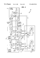
- FIG. 8 shows the protection switching mechanism for system 700 of FIG. 7, according to one embodiment of the present invention.
- the following scenario describes how a protection switch takes place, assuming that all working port functions were active and the protection port function was standby:
- a switch request is received by the PSW processing in the control function or a fault indication is sent to the controller's PSW processing by the FM processing.
- the controller's PSW processing checks whether a protection switch can be performed.
- the controller's PSW processing informs provisioning processing (PROV) within the control function (i.e., the component or components that are responsible for provisioning functions) that the protection port function needs to be provisioned according to the working port function whose operations it will take over.
- provisioning processing within the control function (i.e., the component or components that are responsible for provisioning functions) that the protection port function needs to be provisioned according to the working port function whose operations it will take over.
- the controller's PSW processing sets the bridges and switches in the relay unit and on the switch function.
- the controller's PSW processing indicates to the PSW processing in the appropriate working port function that it is to become standby and to the PSW processing in the protection port function that it is to become active.
- Each port's PSW processing is responsible for handling its own interface selectors in a manner similar to the 1+1 protection scheme of FIG. 3 .
- FIGS. 3-8 show only an exemplary set of the different systems that can be implemented using the present invention.
- the present invention has been described in the context of systems that support three different levels of health for a server (healthy, degraded, and failed), those skilled in the art will understand that versions of the present invention can also be implemented for systems that support only two different levels of server health (i.e., healthy and failed).
Abstract
Description
| TABLE I |
| SERVER FUNCTION STATES |
| ACT | IF | ID | STATE | ||
| 0 | 0 | 0 | Standby | ||
| 0 | 0 | 1 | Degraded Standby | ||
| N/ |
1 | 0/1 | Failed | ||
| 1 | 0 | 0 | Active | ||
| 1 | 0 | 1 | Degraded Active | ||
| TABLE II |
| PROTECTION SWITCHING RULES |
| RULE | SERVER A | | RESPONSE | |
| 1 | Active | Active | Select server that changed to Active most recently* | |
| 2 | Active | Standby | Select Active server* | |
| 3 | Active | Degraded Active | Select Active server* | |
| 4 | Active | Degraded Standby | Select Active server* | |
| 5 | Active | Failed | Select Active server* | |
| 6 | Standby | Standby | Retain previous selection* | |
| 7 | Standby | Degraded Active | If override disabled, then select Standby server, | |
| else select Degraded Active server | ||||
| 8 | Standby | Degraded Standby | If override disabled, then select Standby server, | |
| else retain previous selection | ||||
| 9 | Standby | Failed | If override disabled, then select Standby server, | |
| else retain previous selection | ||||
| 10 | Degraded Active | Degraded Active | Select server that changed state most recently* | |
| 11 | Degraded Active | Degraded Standby | Select Degraded Active server* | |
| 12 | Degraded Active | Failed | Select Degraded Active server* | |
| 13 | Degraded Standby | Degraded Standby | Retain previous selection | |
| 14 | Degraded Standby | Failed | If override disabled, then select Degraded Standby | |
| server, else retain previous selection | ||||
| 15 | Failed | Failed | No protection available | |
Claims (39)
Priority Applications (1)
| Application Number | Priority Date | Filing Date | Title |
|---|---|---|---|
| US09/121,148 US6202170B1 (en) | 1998-07-23 | 1998-07-23 | Equipment protection system |
Applications Claiming Priority (1)
| Application Number | Priority Date | Filing Date | Title |
|---|---|---|---|
| US09/121,148 US6202170B1 (en) | 1998-07-23 | 1998-07-23 | Equipment protection system |
Publications (1)
| Publication Number | Publication Date |
|---|---|
| US6202170B1 true US6202170B1 (en) | 2001-03-13 |
Family
ID=22394869
Family Applications (1)
| Application Number | Title | Priority Date | Filing Date |
|---|---|---|---|
| US09/121,148 Expired - Lifetime US6202170B1 (en) | 1998-07-23 | 1998-07-23 | Equipment protection system |
Country Status (1)
| Country | Link |
|---|---|
| US (1) | US6202170B1 (en) |
Cited By (48)
| Publication number | Priority date | Publication date | Assignee | Title |
|---|---|---|---|---|
| US6449249B1 (en) * | 2000-09-07 | 2002-09-10 | Arris International, Inc. | Spare circuit switching |
| US20030009551A1 (en) * | 2001-06-29 | 2003-01-09 | International Business Machines Corporation | Method and system for a network management framework with redundant failover methodology |
| US20030120967A1 (en) * | 2001-12-21 | 2003-06-26 | Miller Gary M. | Protection switch to support redundant application of converter units |
| US20030128663A1 (en) * | 2002-01-04 | 2003-07-10 | Avaya Technology Corp. | Redundant network controller management system |
| US20030193958A1 (en) * | 2002-04-11 | 2003-10-16 | Vidya Narayanan | Methods for providing rendezvous point router redundancy in sparse mode multicast networks |
| US6658595B1 (en) * | 1999-10-19 | 2003-12-02 | Cisco Technology, Inc. | Method and system for asymmetrically maintaining system operability |
| US6662368B1 (en) * | 2000-09-11 | 2003-12-09 | Arris International, Inc. | Variable spare circuit group size and quantity having multiple active circuits |
| US20040003355A1 (en) * | 2002-06-11 | 2004-01-01 | Carrier Corporation | System and method for implementing configurable finite state machine |
| US6674756B1 (en) | 1999-02-23 | 2004-01-06 | Alcatel | Multi-service network switch with multiple virtual routers |
| WO2004025469A1 (en) * | 2002-09-10 | 2004-03-25 | Union Switch & Signal, Inc. | Hot standby method and apparatus |
| US6766482B1 (en) | 2001-10-31 | 2004-07-20 | Extreme Networks | Ethernet automatic protection switching |
| US20040153584A1 (en) * | 2002-07-30 | 2004-08-05 | Nec Corporation | Information processor |
| US6789118B1 (en) | 1999-02-23 | 2004-09-07 | Alcatel | Multi-service network switch with policy based routing |
| US20050007951A1 (en) * | 2003-07-11 | 2005-01-13 | Roger Lapuh | Routed split multilink trunking |
| US6868057B1 (en) * | 1999-12-08 | 2005-03-15 | Lucent Technologies Inc. | Automatic protection switch decision engine |
| US6914879B1 (en) * | 1999-10-15 | 2005-07-05 | Alcatel | Network element with redundant switching matrix |
| US20050244158A1 (en) * | 2000-12-30 | 2005-11-03 | Siegfried Luft | Method and apparatus for a variable rate pipe on a linear connection |
| US6971042B2 (en) | 2002-04-18 | 2005-11-29 | Huge Systems, Inc. | Media server with single chip storage controller |
| US6980515B1 (en) | 1999-02-23 | 2005-12-27 | Alcatel | Multi-service network switch with quality of access |
| US20060072470A1 (en) * | 2004-10-04 | 2006-04-06 | Fujitsu Network Communications, Inc. | Method and system for monitoring idle network circuits |
| US20060093353A1 (en) * | 2004-10-29 | 2006-05-04 | Alcatel | Optical access node |
| US7085226B1 (en) * | 1999-10-01 | 2006-08-01 | Lg Electronics Inc. | Control apparatus and method for relay node duplexing |
| US20080031260A1 (en) * | 2006-08-07 | 2008-02-07 | Adc Telecommunications, Inc. | Mapping external port using virtual local area network |
| US20080155306A1 (en) * | 2005-12-21 | 2008-06-26 | Combs William E | Method and system for controlling command execution |
| US7436763B1 (en) * | 2002-07-31 | 2008-10-14 | Nortel Networks Limited | Data communication apparatus with a dual mode protection switching system |
| US20080253280A1 (en) * | 2007-01-09 | 2008-10-16 | Sr Telecom Inc. | Redundant Wireless Base Station |
| US20080285437A1 (en) * | 2007-05-18 | 2008-11-20 | Adc Dsl Systems, Inc. | Ethernet protection switching system |
| US20090172155A1 (en) * | 2008-01-02 | 2009-07-02 | International Business Machines Corporation | Method and system for monitoring, communicating, and handling a degraded enterprise information system |
| US20090292816A1 (en) * | 2008-05-21 | 2009-11-26 | Uniloc Usa, Inc. | Device and Method for Secured Communication |
| US7769021B1 (en) * | 2004-07-03 | 2010-08-03 | At&T Corp. | Multiple media fail-over to alternate media |
| US20100325703A1 (en) * | 2009-06-23 | 2010-12-23 | Craig Stephen Etchegoyen | System and Method for Secured Communications by Embedded Platforms |
| US20100321209A1 (en) * | 2009-06-23 | 2010-12-23 | Craig Stephen Etchegoyen | System and Method for Traffic Information Delivery |
| US20100325711A1 (en) * | 2009-06-23 | 2010-12-23 | Craig Stephen Etchegoyen | System and Method for Content Delivery |
| US20100321207A1 (en) * | 2009-06-23 | 2010-12-23 | Craig Stephen Etchegoyen | System and Method for Communicating with Traffic Signals and Toll Stations |
| US20100324821A1 (en) * | 2009-06-23 | 2010-12-23 | Craig Stephen Etchegoyen | System and Method for Locating Network Nodes |
| US20100325719A1 (en) * | 2009-06-19 | 2010-12-23 | Craig Stephen Etchegoyen | System and Method for Redundancy in a Communication Network |
| US20100321208A1 (en) * | 2009-06-23 | 2010-12-23 | Craig Stephen Etchegoyen | System and Method for Emergency Communications |
| US20110010560A1 (en) * | 2009-07-09 | 2011-01-13 | Craig Stephen Etchegoyen | Failover Procedure for Server System |
| CN102025551A (en) * | 2010-12-23 | 2011-04-20 | 中兴通讯股份有限公司 | Method and device for switching master device to backup device based on access gateway |
| US20110107138A1 (en) * | 2007-11-22 | 2011-05-05 | Hitachi, Ltd. | Server switching method and server system equipped therewith |
| US20120127856A1 (en) * | 2009-08-13 | 2012-05-24 | Samsung Sds Co., Ltd. | Electronic patch device, network system, and operation method in network system |
| US20140019799A1 (en) * | 2011-03-31 | 2014-01-16 | Tejas Networks Limited | Method and system of protection switching in a network element |
| US20140355415A1 (en) * | 2011-10-14 | 2014-12-04 | Google Inc. | Semi-centralized routing |
| US20150236951A1 (en) * | 2007-01-22 | 2015-08-20 | Aviat U.S., Inc. | Distributed protection switching architecture for point-to-point microwave radio systems |
| US20150234720A1 (en) * | 2012-09-27 | 2015-08-20 | Nec Corporation | Standby system device, active system device, and load dispersion method |
| US20160285725A1 (en) * | 2015-03-27 | 2016-09-29 | Nec Corporation | System |
| US10572867B2 (en) | 2012-02-21 | 2020-02-25 | Uniloc 2017 Llc | Renewable resource distribution management system |
| CN112114988A (en) * | 2019-06-21 | 2020-12-22 | 顺丰科技有限公司 | Client starting method, device, terminal and storage medium |
Citations (6)
| Publication number | Priority date | Publication date | Assignee | Title |
|---|---|---|---|---|
| US4455645A (en) * | 1980-07-25 | 1984-06-19 | Hitachi, Ltd. | Back-up control system implemented with a redundancy scheme for protection against failure |
| US5193086A (en) * | 1988-08-26 | 1993-03-09 | Hitachi, Ltd. | Network system having a line switching function |
| US5313456A (en) * | 1989-03-03 | 1994-05-17 | Fujitsu Limited | Data link protecting system |
| US5581542A (en) * | 1992-09-30 | 1996-12-03 | Fujitsu Limited | Device and method of performing a switching control to standby system in hybrid system of duplex system and backup line |
| US5796718A (en) * | 1996-09-30 | 1998-08-18 | Mci Communications Corporation | Method of and system for intelligent access line protect switching |
| US5926102A (en) * | 1996-11-16 | 1999-07-20 | Electronics And Telecommunications Research Institute | Method for controlling bidirectional line protection switching by using a remote defect indication signal |
-
1998
- 1998-07-23 US US09/121,148 patent/US6202170B1/en not_active Expired - Lifetime
Patent Citations (6)
| Publication number | Priority date | Publication date | Assignee | Title |
|---|---|---|---|---|
| US4455645A (en) * | 1980-07-25 | 1984-06-19 | Hitachi, Ltd. | Back-up control system implemented with a redundancy scheme for protection against failure |
| US5193086A (en) * | 1988-08-26 | 1993-03-09 | Hitachi, Ltd. | Network system having a line switching function |
| US5313456A (en) * | 1989-03-03 | 1994-05-17 | Fujitsu Limited | Data link protecting system |
| US5581542A (en) * | 1992-09-30 | 1996-12-03 | Fujitsu Limited | Device and method of performing a switching control to standby system in hybrid system of duplex system and backup line |
| US5796718A (en) * | 1996-09-30 | 1998-08-18 | Mci Communications Corporation | Method of and system for intelligent access line protect switching |
| US5926102A (en) * | 1996-11-16 | 1999-07-20 | Electronics And Telecommunications Research Institute | Method for controlling bidirectional line protection switching by using a remote defect indication signal |
Cited By (77)
| Publication number | Priority date | Publication date | Assignee | Title |
|---|---|---|---|---|
| US6980515B1 (en) | 1999-02-23 | 2005-12-27 | Alcatel | Multi-service network switch with quality of access |
| US6789118B1 (en) | 1999-02-23 | 2004-09-07 | Alcatel | Multi-service network switch with policy based routing |
| US6674756B1 (en) | 1999-02-23 | 2004-01-06 | Alcatel | Multi-service network switch with multiple virtual routers |
| US7085226B1 (en) * | 1999-10-01 | 2006-08-01 | Lg Electronics Inc. | Control apparatus and method for relay node duplexing |
| US6914879B1 (en) * | 1999-10-15 | 2005-07-05 | Alcatel | Network element with redundant switching matrix |
| US6658595B1 (en) * | 1999-10-19 | 2003-12-02 | Cisco Technology, Inc. | Method and system for asymmetrically maintaining system operability |
| US6868057B1 (en) * | 1999-12-08 | 2005-03-15 | Lucent Technologies Inc. | Automatic protection switch decision engine |
| US6449249B1 (en) * | 2000-09-07 | 2002-09-10 | Arris International, Inc. | Spare circuit switching |
| US6662368B1 (en) * | 2000-09-11 | 2003-12-09 | Arris International, Inc. | Variable spare circuit group size and quantity having multiple active circuits |
| US20050244158A1 (en) * | 2000-12-30 | 2005-11-03 | Siegfried Luft | Method and apparatus for a variable rate pipe on a linear connection |
| US8200803B2 (en) | 2001-06-29 | 2012-06-12 | International Business Machines Corporation | Method and system for a network management framework with redundant failover methodology |
| US20030009551A1 (en) * | 2001-06-29 | 2003-01-09 | International Business Machines Corporation | Method and system for a network management framework with redundant failover methodology |
| US8032625B2 (en) * | 2001-06-29 | 2011-10-04 | International Business Machines Corporation | Method and system for a network management framework with redundant failover methodology |
| US6766482B1 (en) | 2001-10-31 | 2004-07-20 | Extreme Networks | Ethernet automatic protection switching |
| US20030120967A1 (en) * | 2001-12-21 | 2003-06-26 | Miller Gary M. | Protection switch to support redundant application of converter units |
| US6735718B2 (en) * | 2001-12-21 | 2004-05-11 | Hubbell Incorporated | Protection switch to support redundant application of converter units |
| US20030128663A1 (en) * | 2002-01-04 | 2003-07-10 | Avaya Technology Corp. | Redundant network controller management system |
| US7079481B2 (en) * | 2002-01-04 | 2006-07-18 | Avaya Technology Corp. | Redundant network controller management system |
| US20030193958A1 (en) * | 2002-04-11 | 2003-10-16 | Vidya Narayanan | Methods for providing rendezvous point router redundancy in sparse mode multicast networks |
| US6971042B2 (en) | 2002-04-18 | 2005-11-29 | Huge Systems, Inc. | Media server with single chip storage controller |
| US20040003355A1 (en) * | 2002-06-11 | 2004-01-01 | Carrier Corporation | System and method for implementing configurable finite state machine |
| US7039893B2 (en) * | 2002-06-11 | 2006-05-02 | Carrier Corporation | System and method for implementing configurable finite state machine |
| US20040153584A1 (en) * | 2002-07-30 | 2004-08-05 | Nec Corporation | Information processor |
| US7137029B2 (en) * | 2002-07-30 | 2006-11-14 | Nec Corporation | Information processor |
| US7436763B1 (en) * | 2002-07-31 | 2008-10-14 | Nortel Networks Limited | Data communication apparatus with a dual mode protection switching system |
| WO2004025469A1 (en) * | 2002-09-10 | 2004-03-25 | Union Switch & Signal, Inc. | Hot standby method and apparatus |
| US7437605B2 (en) | 2002-09-10 | 2008-10-14 | Union Switch & Signal, Inc. | Hot standby method and apparatus |
| US20070168710A1 (en) * | 2002-09-10 | 2007-07-19 | Blevins Joseph S Sr | Hot standby method and apparatus |
| US7463579B2 (en) * | 2003-07-11 | 2008-12-09 | Nortel Networks Limited | Routed split multilink trunking |
| US20050007951A1 (en) * | 2003-07-11 | 2005-01-13 | Roger Lapuh | Routed split multilink trunking |
| US8934349B2 (en) | 2004-07-03 | 2015-01-13 | At&T Intellectual Property Ii, L.P. | Multiple media fail-over to alternate media |
| US8385351B1 (en) | 2004-07-03 | 2013-02-26 | At&T Intellectual Property Ii, L.P. | Multiple media fail-over to alternate media |
| US8737232B2 (en) | 2004-07-03 | 2014-05-27 | At&T Intellectual Property Ii, L.P. | Multiple media fail-over to alternate media |
| US7769021B1 (en) * | 2004-07-03 | 2010-08-03 | At&T Corp. | Multiple media fail-over to alternate media |
| US7471637B2 (en) * | 2004-10-04 | 2008-12-30 | Fujitsu Limited | Method and system for monitoring idle network circuits |
| US20060072470A1 (en) * | 2004-10-04 | 2006-04-06 | Fujitsu Network Communications, Inc. | Method and system for monitoring idle network circuits |
| US20060093353A1 (en) * | 2004-10-29 | 2006-05-04 | Alcatel | Optical access node |
| US20080155306A1 (en) * | 2005-12-21 | 2008-06-26 | Combs William E | Method and system for controlling command execution |
| US7577870B2 (en) * | 2005-12-21 | 2009-08-18 | The Boeing Company | Method and system for controlling command execution |
| US8116320B2 (en) | 2006-08-07 | 2012-02-14 | Adc Telecommunications, Inc. | Mapping external port using virtual local area network |
| US20080031260A1 (en) * | 2006-08-07 | 2008-02-07 | Adc Telecommunications, Inc. | Mapping external port using virtual local area network |
| US20080253280A1 (en) * | 2007-01-09 | 2008-10-16 | Sr Telecom Inc. | Redundant Wireless Base Station |
| US9479430B2 (en) * | 2007-01-22 | 2016-10-25 | Aviat U.S., Inc. | Distributed protection switching architecture for point-to-point microwave radio systems |
| US20150236951A1 (en) * | 2007-01-22 | 2015-08-20 | Aviat U.S., Inc. | Distributed protection switching architecture for point-to-point microwave radio systems |
| EP2147528A1 (en) * | 2007-05-18 | 2010-01-27 | ADC DSL Systems, Inc. | An ethernet protection switching system |
| CN101953122A (en) * | 2007-05-18 | 2011-01-19 | Adcdsl系统公司 | Ethernet protection exchanging system |
| US20080285437A1 (en) * | 2007-05-18 | 2008-11-20 | Adc Dsl Systems, Inc. | Ethernet protection switching system |
| EP2147528A4 (en) * | 2007-05-18 | 2013-11-06 | Adc Dsl Sys Inc | An ethernet protection switching system |
| US20110107138A1 (en) * | 2007-11-22 | 2011-05-05 | Hitachi, Ltd. | Server switching method and server system equipped therewith |
| US8386830B2 (en) * | 2007-11-22 | 2013-02-26 | Hitachi, Ltd. | Server switching method and server system equipped therewith |
| US20090172155A1 (en) * | 2008-01-02 | 2009-07-02 | International Business Machines Corporation | Method and system for monitoring, communicating, and handling a degraded enterprise information system |
| US20090292816A1 (en) * | 2008-05-21 | 2009-11-26 | Uniloc Usa, Inc. | Device and Method for Secured Communication |
| US8812701B2 (en) | 2008-05-21 | 2014-08-19 | Uniloc Luxembourg, S.A. | Device and method for secured communication |
| US20100325719A1 (en) * | 2009-06-19 | 2010-12-23 | Craig Stephen Etchegoyen | System and Method for Redundancy in a Communication Network |
| US20100321209A1 (en) * | 2009-06-23 | 2010-12-23 | Craig Stephen Etchegoyen | System and Method for Traffic Information Delivery |
| US20100325711A1 (en) * | 2009-06-23 | 2010-12-23 | Craig Stephen Etchegoyen | System and Method for Content Delivery |
| US20100321207A1 (en) * | 2009-06-23 | 2010-12-23 | Craig Stephen Etchegoyen | System and Method for Communicating with Traffic Signals and Toll Stations |
| US8452960B2 (en) | 2009-06-23 | 2013-05-28 | Netauthority, Inc. | System and method for content delivery |
| US20100324821A1 (en) * | 2009-06-23 | 2010-12-23 | Craig Stephen Etchegoyen | System and Method for Locating Network Nodes |
| US20100325703A1 (en) * | 2009-06-23 | 2010-12-23 | Craig Stephen Etchegoyen | System and Method for Secured Communications by Embedded Platforms |
| US8736462B2 (en) | 2009-06-23 | 2014-05-27 | Uniloc Luxembourg, S.A. | System and method for traffic information delivery |
| US8903653B2 (en) | 2009-06-23 | 2014-12-02 | Uniloc Luxembourg S.A. | System and method for locating network nodes |
| US20100321208A1 (en) * | 2009-06-23 | 2010-12-23 | Craig Stephen Etchegoyen | System and Method for Emergency Communications |
| US9141489B2 (en) | 2009-07-09 | 2015-09-22 | Uniloc Luxembourg S.A. | Failover procedure for server system |
| US20110010560A1 (en) * | 2009-07-09 | 2011-01-13 | Craig Stephen Etchegoyen | Failover Procedure for Server System |
| US20120127856A1 (en) * | 2009-08-13 | 2012-05-24 | Samsung Sds Co., Ltd. | Electronic patch device, network system, and operation method in network system |
| US9369337B2 (en) * | 2009-08-13 | 2016-06-14 | Samsung Sds Co., Ltd. | Electronic patch device, network system, and operation method in network system |
| CN102025551A (en) * | 2010-12-23 | 2011-04-20 | 中兴通讯股份有限公司 | Method and device for switching master device to backup device based on access gateway |
| US20140019799A1 (en) * | 2011-03-31 | 2014-01-16 | Tejas Networks Limited | Method and system of protection switching in a network element |
| US9396075B2 (en) * | 2011-03-31 | 2016-07-19 | Tejas Networks Limited | Method and system of protection switching in a network element |
| US20140355415A1 (en) * | 2011-10-14 | 2014-12-04 | Google Inc. | Semi-centralized routing |
| US10572867B2 (en) | 2012-02-21 | 2020-02-25 | Uniloc 2017 Llc | Renewable resource distribution management system |
| US20150234720A1 (en) * | 2012-09-27 | 2015-08-20 | Nec Corporation | Standby system device, active system device, and load dispersion method |
| US20160285725A1 (en) * | 2015-03-27 | 2016-09-29 | Nec Corporation | System |
| US10158526B2 (en) * | 2015-03-27 | 2018-12-18 | Nec Corporation | System that manages server function |
| CN112114988A (en) * | 2019-06-21 | 2020-12-22 | 顺丰科技有限公司 | Client starting method, device, terminal and storage medium |
| CN112114988B (en) * | 2019-06-21 | 2023-03-31 | 顺丰科技有限公司 | Client starting method, device, terminal and storage medium |
Similar Documents
| Publication | Publication Date | Title |
|---|---|---|
| US6202170B1 (en) | Equipment protection system | |
| US5983371A (en) | Active failure detection | |
| US20050058063A1 (en) | Method and system supporting real-time fail-over of network switches | |
| JPH07235933A (en) | Fault-torelant connection method and device to local area network of computor system | |
| CN1937528A (en) | Information processing apparatuses, communication load decentralizing method and communication system | |
| US20070270984A1 (en) | Method and Device for Redundancy Control of Electrical Devices | |
| US20030023892A1 (en) | Peer-to-peer redundancy control scheme with override feature | |
| US6618819B1 (en) | Sparing system and method to accommodate equipment failures in critical systems | |
| US20050060394A1 (en) | Programmable delay, transparent switching multi-port interface line card | |
| JP5176914B2 (en) | Transmission device and system switching method for redundant configuration unit | |
| KR960010879B1 (en) | Bus duplexing control of multiple processor | |
| KR100237370B1 (en) | A switchover method for duplicated operational workstation server | |
| CN108494534A (en) | A kind of self-propelled air defense weapon system dual redundant Ethernet design method | |
| KR100438066B1 (en) | Method for switching Plural LAN in network system | |
| JP7346172B2 (en) | communication equipment | |
| JP2989091B2 (en) | Data switch | |
| KR100296403B1 (en) | Redundancy Implementation in Communication Systems | |
| US7590717B1 (en) | Single IP address for redundant shelf processors | |
| KR100303344B1 (en) | A method for managing protocol and system switching priority for system redundancy | |
| KR100228306B1 (en) | Hot-standby multiplexer and implementation method | |
| KR100220900B1 (en) | Communication network duplication apparatus | |
| JPH04239831A (en) | Inter processor backup system | |
| KR100306482B1 (en) | N:1 Duplex System And Duplex Control Method In That System | |
| JPH0563802A (en) | Duplicate equipment for exchange | |
| KR950016088A (en) | Interconnecting device between each communication network between processors and its operation method |
Legal Events
| Date | Code | Title | Description |
|---|---|---|---|
| AS | Assignment |
Owner name: LUCENT TECHNOLOGIES INC., NEW JERSEY Free format text: ASSIGNMENT OF ASSIGNORS INTEREST;ASSIGNORS:BUSSCHBACH, PETER B.;STEINBERGER, MICHAEL L.;REEL/FRAME:009339/0096;SIGNING DATES FROM 19980716 TO 19980718 |
|
| FEPP | Fee payment procedure |
Free format text: PAYOR NUMBER ASSIGNED (ORIGINAL EVENT CODE: ASPN); ENTITY STATUS OF PATENT OWNER: LARGE ENTITY |
|
| STCF | Information on status: patent grant |
Free format text: PATENTED CASE |
|
| FPAY | Fee payment |
Year of fee payment: 4 |
|
| FPAY | Fee payment |
Year of fee payment: 8 |
|
| FPAY | Fee payment |
Year of fee payment: 12 |
|
| AS | Assignment |
Owner name: PROVENANCE ASSET GROUP LLC, CONNECTICUT Free format text: ASSIGNMENT OF ASSIGNORS INTEREST;ASSIGNORS:NOKIA TECHNOLOGIES OY;NOKIA SOLUTIONS AND NETWORKS BV;ALCATEL LUCENT SAS;REEL/FRAME:043877/0001 Effective date: 20170912 Owner name: NOKIA USA INC., CALIFORNIA Free format text: SECURITY INTEREST;ASSIGNORS:PROVENANCE ASSET GROUP HOLDINGS, LLC;PROVENANCE ASSET GROUP LLC;REEL/FRAME:043879/0001 Effective date: 20170913 Owner name: CORTLAND CAPITAL MARKET SERVICES, LLC, ILLINOIS Free format text: SECURITY INTEREST;ASSIGNORS:PROVENANCE ASSET GROUP HOLDINGS, LLC;PROVENANCE ASSET GROUP, LLC;REEL/FRAME:043967/0001 Effective date: 20170913 |
|
| AS | Assignment |
Owner name: NOKIA US HOLDINGS INC., NEW JERSEY Free format text: ASSIGNMENT AND ASSUMPTION AGREEMENT;ASSIGNOR:NOKIA USA INC.;REEL/FRAME:048370/0682 Effective date: 20181220 |
|
| AS | Assignment |
Owner name: PROVENANCE ASSET GROUP LLC, CONNECTICUT Free format text: RELEASE BY SECURED PARTY;ASSIGNOR:CORTLAND CAPITAL MARKETS SERVICES LLC;REEL/FRAME:058983/0104 Effective date: 20211101 Owner name: PROVENANCE ASSET GROUP HOLDINGS LLC, CONNECTICUT Free format text: RELEASE BY SECURED PARTY;ASSIGNOR:CORTLAND CAPITAL MARKETS SERVICES LLC;REEL/FRAME:058983/0104 Effective date: 20211101 Owner name: PROVENANCE ASSET GROUP LLC, CONNECTICUT Free format text: RELEASE BY SECURED PARTY;ASSIGNOR:NOKIA US HOLDINGS INC.;REEL/FRAME:058363/0723 Effective date: 20211129 Owner name: PROVENANCE ASSET GROUP HOLDINGS LLC, CONNECTICUT Free format text: RELEASE BY SECURED PARTY;ASSIGNOR:NOKIA US HOLDINGS INC.;REEL/FRAME:058363/0723 Effective date: 20211129 |
|
| AS | Assignment |
Owner name: RPX CORPORATION, CALIFORNIA Free format text: ASSIGNMENT OF ASSIGNORS INTEREST;ASSIGNOR:PROVENANCE ASSET GROUP LLC;REEL/FRAME:059352/0001 Effective date: 20211129 |