US6204978B1 - Optical system - Google Patents
Optical system Download PDFInfo
- Publication number
- US6204978B1 US6204978B1 US09/361,966 US36196699A US6204978B1 US 6204978 B1 US6204978 B1 US 6204978B1 US 36196699 A US36196699 A US 36196699A US 6204978 B1 US6204978 B1 US 6204978B1
- Authority
- US
- United States
- Prior art keywords
- cos
- reflecting surface
- lens unit
- optical system
- azimuth
- Prior art date
- Legal status (The legal status is an assumption and is not a legal conclusion. Google has not performed a legal analysis and makes no representation as to the accuracy of the status listed.)
- Expired - Lifetime
Links
Images


Classifications
-
- G—PHYSICS
- G02—OPTICS
- G02B—OPTICAL ELEMENTS, SYSTEMS OR APPARATUS
- G02B17/00—Systems with reflecting surfaces, with or without refracting elements
- G02B17/08—Catadioptric systems
- G02B17/0856—Catadioptric systems comprising a refractive element with a reflective surface, the reflection taking place inside the element, e.g. Mangin mirrors
- G02B17/086—Catadioptric systems comprising a refractive element with a reflective surface, the reflection taking place inside the element, e.g. Mangin mirrors wherein the system is made of a single block of optical material, e.g. solid catadioptric systems
-
- G—PHYSICS
- G02—OPTICS
- G02B—OPTICAL ELEMENTS, SYSTEMS OR APPARATUS
- G02B13/00—Optical objectives specially designed for the purposes specified below
- G02B13/18—Optical objectives specially designed for the purposes specified below with lenses having one or more non-spherical faces, e.g. for reducing geometrical aberration
-
- G—PHYSICS
- G02—OPTICS
- G02B—OPTICAL ELEMENTS, SYSTEMS OR APPARATUS
- G02B17/00—Systems with reflecting surfaces, with or without refracting elements
- G02B17/02—Catoptric systems, e.g. image erecting and reversing system
- G02B17/06—Catoptric systems, e.g. image erecting and reversing system using mirrors only, i.e. having only one curved mirror
- G02B17/0626—Catoptric systems, e.g. image erecting and reversing system using mirrors only, i.e. having only one curved mirror using three curved mirrors
- G02B17/0642—Catoptric systems, e.g. image erecting and reversing system using mirrors only, i.e. having only one curved mirror using three curved mirrors off-axis or unobscured systems in which not all of the mirrors share a common axis of rotational symmetry, e.g. at least one of the mirrors is warped, tilted or decentered with respect to the other elements
-
- G—PHYSICS
- G02—OPTICS
- G02B—OPTICAL ELEMENTS, SYSTEMS OR APPARATUS
- G02B17/00—Systems with reflecting surfaces, with or without refracting elements
- G02B17/02—Catoptric systems, e.g. image erecting and reversing system
- G02B17/06—Catoptric systems, e.g. image erecting and reversing system using mirrors only, i.e. having only one curved mirror
- G02B17/0647—Catoptric systems, e.g. image erecting and reversing system using mirrors only, i.e. having only one curved mirror using more than three curved mirrors
- G02B17/0663—Catoptric systems, e.g. image erecting and reversing system using mirrors only, i.e. having only one curved mirror using more than three curved mirrors off-axis or unobscured systems in which not all of the mirrors share a common axis of rotational symmetry, e.g. at least one of the mirrors is warped, tilted or decentered with respect to the other elements
-
- G—PHYSICS
- G02—OPTICS
- G02B—OPTICAL ELEMENTS, SYSTEMS OR APPARATUS
- G02B17/00—Systems with reflecting surfaces, with or without refracting elements
- G02B17/08—Catadioptric systems
- G02B17/0804—Catadioptric systems using two curved mirrors
- G02B17/0816—Catadioptric systems using two curved mirrors off-axis or unobscured systems in which not all of the mirrors share a common axis of rotational symmetry, e.g. at least one of the mirrors is warped, tilted or decentered with respect to the other elements
-
- G—PHYSICS
- G02—OPTICS
- G02B—OPTICAL ELEMENTS, SYSTEMS OR APPARATUS
- G02B17/00—Systems with reflecting surfaces, with or without refracting elements
- G02B17/08—Catadioptric systems
- G02B17/082—Catadioptric systems using three curved mirrors
- G02B17/0832—Catadioptric systems using three curved mirrors off-axis or unobscured systems in which not all of the mirrors share a common axis of rotational symmetry, e.g. at least one of the mirrors is warped, tilted or decentered with respect to the other elements
-
- G—PHYSICS
- G02—OPTICS
- G02B—OPTICAL ELEMENTS, SYSTEMS OR APPARATUS
- G02B17/00—Systems with reflecting surfaces, with or without refracting elements
- G02B17/08—Catadioptric systems
- G02B17/0836—Catadioptric systems using more than three curved mirrors
- G02B17/0848—Catadioptric systems using more than three curved mirrors off-axis or unobscured systems in which not all of the mirrors share a common axis of rotational symmetry, e.g. at least one of the mirrors is warped, tilted or decentered with respect to the other elements
-
- G—PHYSICS
- G02—OPTICS
- G02B—OPTICAL ELEMENTS, SYSTEMS OR APPARATUS
- G02B27/00—Optical systems or apparatus not provided for by any of the groups G02B1/00 - G02B26/00, G02B30/00
- G02B27/01—Head-up displays
- G02B27/0101—Head-up displays characterised by optical features
- G02B2027/011—Head-up displays characterised by optical features comprising device for correcting geometrical aberrations, distortion
Definitions
- This invention relates to an optical system, and particularly to an optical system including a curved surface (off-axial curved surface) on which with the route of a certain reference axis ray leading from an object surface to an image surface as a reference axis, a surface normal at a point on which the reference axis is incident does not coincide with the reference axis.
- a curved surface off-axial curved surface
- an optical system for forming the image of an object on an object surface onto an image surface use has heretofore been made of a coaxial optical system in which on an optical axis, there is disposed a refracting surface or a reflecting surface rotation-symmetrical with respect to the optical axis.
- an off-axial reflecting surface or the like is used and therefore, the occurrence of eccentric aberration is unavoidable.
- astigmatism on-axis astigmatism
- power refractive power
- the present invention has as its object the provision of an optical system including an off-axial curved surface in which some of a plurality of groups (or surfaces) constituting it are designed such that the power thereof has azimuth dependency, and as a whole, the azimuth dependency of the power is null in such a manner that the some groups (or surfaces) negate the azimuth dependency with one another, and primary spherical aberration (on-axis astigmatism) is corrected.
- optical system of the present invention is a
- an optical system having three partial systems through which rays of light from an object pass i.e., a first partial system having at least one off-axial curved surface, a second partial system and a third partial system having at least one off-axial curved surface, characterized in that when the route of a ray of light passing from the object through the center of a stop to the center of the last image surface is defined as a reference axis and the converted principal point interval between the first partial system and the second partial system is defined as e1 and the converted principal point interval between the second partial system and the third partial system is defined as e2 and the power of the second partial system at a certain azimuth angle is defined as ⁇ 2 ( ⁇ ), the condition that 0.8 ⁇ ⁇
- ⁇ ⁇ ⁇ 2 ⁇ ⁇ m 1 / 2 ⁇ ⁇ ⁇ ⁇ 0 2 ⁇ ⁇ ⁇ ⁇ 2 ⁇ (
- optical system of the present invention is a
- an optical system having a transparent body provided with three reflecting surfaces by which rays of light from an object are internally reflected and pass, i.e., a first reflecting surface, a second reflecting surface and a third reflecting surface, characterized in that when the route of a ray of light passing from the object through the center of a stop to the center of the last image surface is defined as a reference axis and the converted interval between the first reflecting surface and the second reflecting surface is defined as e1 and the converted interval between the second reflecting surface and the third reflecting surface is defined as e2 and the power of the second reflecting surface at a certain azimuth angle is defined as ⁇ 2 ( ⁇ ), the condition that
- optical system of the present invention is a
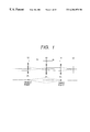
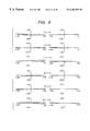
- FIG. 1 shows the basic construction of the optical system of the present invention as a coaxial system.
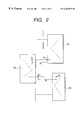
- FIG. 2 shows the specific construction of the optical system of the present invention.
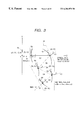
- FIG. 3 is an illustration of a coordinate system.
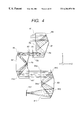
- FIG. 4 is a cross-sectional view of Embodiment 1 of the optical system of the present invention.
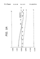
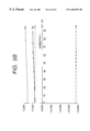
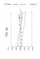
- FIGS. 5A, 5 B and 5 C show the azimuth dependency of the powers in each lens unit and the entire system of Embodiment 1.
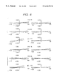
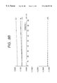
- FIG. 6 shows the lateral aberration of Embodiment 1.
- FIG. 7 is a cross-sectional view of Embodiment 2 of the optical system of the present invention.
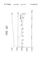
- FIGS. 8A, 8 B and 8 C show the azimuth dependency of the powers in each lens unit and the entire system of Embodiment 2.
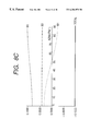
- FIG. 9 shows the lateral aberration of Embodiment 2.
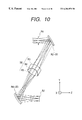
- FIG. 10 is a cross-sectional view of Embodiment 3 of the optical system of the present invention.
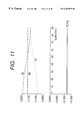
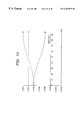
- FIG. 11 shows the azimuth dependency of the powers in each lens unit and the entire system of Embodiment 3.
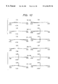
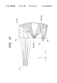
- FIG. 12 shows the lateral aberration of Embodiment 3.
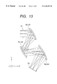
- FIG. 13 is a cross-sectional view of Embodiment 4 of the optical system of the present invention.
- FIG. 14 shows the azimuth dependency of the powers in each surface and the entire system of Embodiment 4.
- FIG. 15 shows the lateral aberration of Embodiment 4.
- FIG. 16 is a cross-sectional view of Embodiment 5 of the optical system of the present invention.
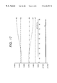
- FIG. 17 shows the azimuth dependency of the powers in each surface and the entire system of Embodiment 5.
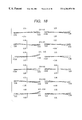
- FIG. 18 shows the lateral aberration of Embodiment 5.
- FIG. 19 is a cross-sectional view of Embodiment 6 of the optical system of the present invention.
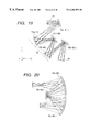
- FIG. 20 is a cross-sectional view of the third surface R3 to the fifth surface R5 of Embodiment 6.
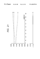
- FIG. 21 shows the azimuth dependency of each of the third surface R3 to the fifth surface R5 of Embodiment 6 and composite power.
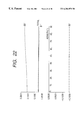
- FIG. 22 shows the azimuth dependency of the powers of the second surface R2, the partial system between the third to fifth surface, the sixth surface R6 and the entire system of Embodiment 6.
- FIG. 23 shows the lateral aberration of Embodiment 6.
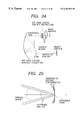
- FIG. 24 shows an example of an off-axial optical system.
- FIG. 25 shows a method of expression in which the point of intersection between the reference axis and surface of an off-axial optical system used in the present invention is the origin.
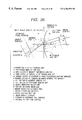
- FIG. 26 shows a paraxially developed coordinate system along a bent reference axis and various amounts used therein.
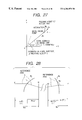
- FIG. 27 shows the decomposition of the components of an image point vector.
- FIG. 28 shows the principal point, focal point and focal length of the off-axial optical system.
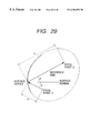
- FIG. 29 shows an example of an off-axial reflection quadratic surface in which the reference axis passes through two focal points.
- the focal length changing optical system of the present invention is a so-called eccentric or decentering optical system (off-axial optical system) using an eccentric or decentering reflecting surface.
- eccentric optical system eccentric or decentering optical system
- the concept of a reference axis corresponding to the optical axis of a coaxial system is introduced, and a paraxial theory is evolved about this reference axis to thereby effect the designing of the eccentric optical system.
- the paraxial theory of the eccentric optical system (herein also called the off-axial optical system) will hereinafter be described.
- the off-axial optical system and a reference axis which is the framework thereof will be defined as follows.
- the optical path of a certain ray of light of a reference wavelength which is the reference leading from an object surface to an image surface is defined as the “reference axis” in that optical system.
- the ray of light which is the reference is not defined by this alone and therefore, usually the reference axis ray is set in conformity to one of the following two fundamental rules:
- a ray of light passing on the axis having symmetry shall be a reference-axis ray.
- a ray of light passing from the center of an object surface (the center of a range to be photographed or to be observed) and then passing through the designated surface of the optical system and passing through the center of a stop in the optical system, or a ray of light passing through the center of the stop in the optical system to the center of the last image surface is set as a reference-axis ray, and the optical path thereof shall be a reference axis.
- the reference axis defined in this manner is generally of a bent shape (see FIG. 24 ).
- each surface the point of intersection between each surface and the reference axis ray shall be the reference point of each surface, and the reference-axis ray on the object side of each surface shall be the incidence reference axis, and the reference axis ray on the image side of each surface shall be the emergence reference axis.
- the reference axis shall have a direction (sense), and the direction shall be a direction in which the reference axis ray travels when it is imaged. Consequently, the incidence reference axis direction and the emergence reference axis direction exist on the incidence and emergence sides, respectively. In this manner, the reference axis finally arrives at the image surface while having its direction changed along the order of the set surfaces in accordance with the law of refraction or reflection.
- the reference-axis ray incident on the surface thereof most adjacent to the object side shall be the incidence reference axis of this optical element (optical system), and the reference-axis ray emerging from the surface thereof most adjacent to the image side shall be the emergence reference axis of this optical element (optical system). Also, the definition of the directions of these incidence and emergence reference axes is the same as that in the case of the surfaces.
- An optical system including a curved surface (off-axial curved surface) in which at the reference point whereat the reference axis defined as described above intersects with a curved surface, a surface normal does not coincide with the reference axis is defined as an off-axial optical system, and an example thereof is shown in FIG. 24 .
- the surface normal does not coincide with the reference axis, but yet the flat reflecting surface does not spoil the symmetry of aberration and is therefore excluded from the subject of the off-axial optical system.
- This definition also covers an optical system in which a part of a coaxial optical system is greatly eccentric, but generally in an asymmetrical aspherical system, there is no point or line having the symmetry of the meaning of “centric” in “eccentric”. So, in this paraxial theory, the word “eccentric” is not positively used, but the word “off-axial” is used.
- Surfaces constituting the off-axial optical system generally do not have symmetry.
- Most popular as a method of expressing a surface which does not have symmetry is two-variable power series evolution to the center of evolution.
- the center of evolution is the point of intersection between the surface and the reference axis, i.e., the reference point, and as a local coordinate system for expressing the surface shape thereof, use is made of the z-axis set to a surface normal.
- evolution is begun from secondary so that the surface normal at the reference point may not change with a change in the surface shape, and is represented as follows.
- the constituent surface is defined by the use of the technique of evolving with the surface normal thus fixed about the reference point, the surface shape can be changed without the framework of the optical arrangement (the disposition of the reference axis) being changed, as shown in FIG. 25, unlike the conventional method of designing an off-axial optical system. Further, if only the tertiary and subsequent coefficients are changed with the secondary evolution coefficient also fixed, only aberration correction can also be effected without the paraxial amount at each azimuth (see the result of (numerical expression 8) to (numerical expression 11) which will be described later) being changed.
- FIG. 26 shows the coordinate system of paraxial evolution along a bent reference axis used in the analysis and various amounts used therein. Reflection can be generalized with refraction in which the refractive index is negative and therefore, evolution is considered in a refracting system.
- a local coordinate system is taken along the reference axis, and the object surface, the image surface, the entrance pupil surface and the exit pupil surface are defined perpendicularly to the reference axis as shown.
- the surface shape as previously described, is expressed by a local coordinate system having a surface normal as the z-axis.
- b′ ⁇ b+ ⁇ + ⁇ , (numerical expression 4) where ⁇ b+ ⁇ represents a parallel component vector to the azimuth ⁇ ( ⁇ is the lateral magnification of projection determined by (numerical expression 11) which will be described later), and ⁇ represents a perpendicular component vector.
- the object height b may be put as 0. Accordingly, the primary coefficients of proportion of ⁇ and r of ⁇ can be examined, but reflecting the fact that due to the rotation asymmetry of the system, the paraxial ray is at a position twisted relative to the reference axis, these two coefficients have azimuth dependency and generally the two coefficients cannot be rendered into 0 at a time.
- a i and D i in the expressions of refraction are generally not 1 and that A i , D i and ⁇ i have azimuth dependency. Accordingly, if the paraxial amount at each azimuth is calculated, it is possible to examine the azimuth dependency of the paraxial amount. (In the numerical expressions herein, the symbol ⁇ or * represents multiplication.)
- F represents the object side focal point
- H represents the object side principal point
- F′ represents the image side focal point
- H′ represents the image side principal point.
- the power of the reflecting surface can be made so as not to depend on the azimuth ⁇ .
- the coefficient of the secondary term when a general spherical expression is series-evolved is represented by 1/(2r) when the radius of curvature is defined as r and therefore, if in the coordinate system in (numerical expression 1), the radius of curvature of the paraxial region in xz plane is defined as r x and the radius of curvature of the paraxial region in yz plane is defined as r y , the aforementioned coefficient is represented as
- the focal lengths at all azimuths coincide with one another on the eccentric reflecting surface.
- paraxial theory of the off-axial system and the technique of paraxial trace built in the manner described above can be applied to the design the off-axial system.
- design can be done, for example, in the following procedure.
- the optical system is disposed along a bent reference axis with the interference of the optical path or the like taken into consideration.
- paraxial trace is effected at each azimuth and the curvature of each surface is determined so that the paraxial amount and image surface position of the entire system may not have azimuth dependency.
- the final imaging state what is required as the performance of the optical system is the final imaging state, and whatever may be the imaging state of the interior (middle) of the optical system.
- the optical system is constituted by three reflecting surfaces and the powers of the respective surfaces are ⁇ 1 ( ⁇ ), ⁇ 2 ( ⁇ ) and ⁇ 3 ( ⁇ ) and the converted intervals (intervals converted into dimensions in the air) among the respective surfaces are defined as e 1 and e 2 , there are obtained
- ⁇ 2 ( ⁇ ) ( e 1 +e 2 )/( e 1 *e 2 ) (1)
- ⁇ 3 ( ⁇ ) ⁇ [( e 1 /e 2 ) 2 ( ⁇ 1 ( ⁇ ) ⁇ 1 m )].
- the second surface is an isotropic surface free of azimuth dependency
- the first surface and the third surface are located at conjugate positions with respect to this second surface, and the azimuth dependency of the first surface and the azimuth dependency of the third surface try to negate the azimuth dependency of the entire system.
- the second lens unit is a lens unit free of azimuth dependency as a whole and the converted principal point interval (principal point interval converted into a demension in the air) from the image side principal point of the first group to the object side principal point of the second lens unit is defined as e 1 and the converted principal point interval from the image side principal point of the second lens unit to the object side principal point of the third lens unit is defined as e 2 and the image side principal point of the first lens unit and the object side principal point of the third lens unit are set at conjugate positions with respect to the second lens unit.
- the converted principal point interval principal point interval converted into a demension in the air
- FIG. 1 shows the basic construction of the optical system of the present invention as a coaxial system.
- a light beam coming from the object side passes through a first lens unit 12 , a second lens unit 13 and a third lens unit 14 in the named order, and is imaged on the last imaging surface 16 .
- the first lens unit 12 has the azimuth dependency of power
- the second lens unit 13 does not have the azimuth dependency of power
- the third lens unit 14 has the azimuth dependency of power.
- ⁇ 2 ( e 1 +e 2 )/( e 1 *e 2 ),
- ⁇ 3 ( ⁇ ) ⁇ [( e 1 /e 2 ) 2 ( ⁇ 1( ⁇ ) ⁇ 1 m )],
- the system can be constructed such that the first lens unit and the third lens unit have azimuth dependency, but yet the whole does not have azimuth dependency.
- azimuth dependency will become completely null, but even if there is some deviation from the equalities, the azimuth dependency of the power of the entire system will not become so great. This become entangled with the problem of to what extent azimuth dependency can be permitted in conformity with the use of the optical system.
- FIG. 2 shows the specific construction of the optical arrangement of FIG. 1 .
- the reference characters B1, B2 and B3 designate a first lens unit (or a first partial system), a second lens unit (or a second partial system) and a third lens unit (or a third partial system), respectively, having a plurality of off-axial reflecting surfaces, and correspond to the first lens unit 12 , the second lens unit 13 and the third lens unit 14 , respectively, in FIG. 1.
- a dot-and-dash line indicates a principal ray of the central angle of view and this principal ray repeats reflection in each lens unit by a reflecting surface, not shown, and passes to the last imaging surface 16 via each lens unit.
- the optical system of the present invention is an off-axial reflecting system, and an optical axis called so in a coaxial system does not definitely exist in it. Consequently, as previously described, the reference axis is defined with one of rays of light leaving the center of the object surface which passes through the center of a stop defined in the optical system to the center of the last image surface as a reference ray.
- a dot-and-dash line indicates the reference ray.
- the object side principal point of each lens unit lies on the entrance reference axis, and the image side principal point of each lens unit lies on the exit reference axis.
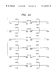
- FIG. 3 is an illustration of a coordinate system defining the construction data of the optical system of the present invention.
- the ith surface along a ray travelling from the object side to the image surface shall be the ith surface.
- the first surface R1 is a stop
- the second surface R2 is a refracting surface coaxial with the first surface
- the third surface R3 is a reflecting surface tilted relative to the second surface R2
- the fourth surface R4 and the fifth surface R5 are reflecting surfaces shifted and tilted relative to their preceding surfaces
- the sixth surface R6 is a refracting surface shifted and tilted relative to the fifth surface R5.
- Each of the second surface R2 to the sixth surface R6 is constructed on an optical element formed of a medium such as glass or plastic, and in FIG. 3, it is the first optical element B1.
- the medium of the object surface, not shown, to the second surface R2 is air
- the medium of the second surface R2 to the sixth surface R6 is a certain common medium
- the medium of the sixth surface R6 to the seventh surface R7, not shown, is air.
- the optical system of the present invention is an off-axial optical system and therefore, the surfaces constituting the optical system do not have a common optical axis. So, in the embodiments of the present invention, an absolute coordinate system having the center of the effective diameter of the ray of the first surface R1 as the origin is first set.
- the axes of the absolute coordinate system are defined as follows:
- Z-axis reference axis passing through the origin to the second surface R2
- Y-axis straight line passing through the origin and counter-clockwisely forming 90° with respect to the Z-axis in a tilt plane (the plane of the drawing sheet of FIG. 3)
- X-axis straight line passing through the origin and perpendicular to the Z-axis and the Y-axis (straight line perpendicular to the plane of the drawing sheet of FIG. 3)
- the surface shape of the ith surface constituting the optical system
- the angle of tilt of the ith surface in YZ plane is represented by an angle ⁇ i (unit being °) in which the counter-clockwise direction relative to the Z-axis of an absolute coordinate system is positive. Consequently, in the embodiments of the present invention, the origin of the local coordinates of each surface lies on the YZ plane in FIG. 3 . There are no tilt and shift of the surfaces in the XZ and XY planes. Further, the y- and z-axis of the local coordinates (x, y, z) of the ith surface are inclined by an angle ⁇ i in YZ plane relative to the absolute coordinate system (X, Y, Z) and specifically are set as follows:
- z-axis straight line passing through the origin of the local coordinates and counter-clockwisely forming an angle ⁇ i in the YZ plane relative to the Z direction of the absolute coordinate system
- y-axis straight line passing through the origin of the local coordinates and counter-clockwisely forming 90° in the YZ plane relative to Z direction
- x-axis straight line passing through the origin of the local coordinates and perpendicular to the YZ plane
- Di is a scalar amount representative of the interval between the origins of the local coordinates of the ith surface and the (i+1)th surface
- Ndi and vdi are the refractive index and Abbe number, respectively, of the medium between the ith surface and the (i+1)th surface.
- the embodiments of the present invention have a spherical surface and a rotation-asymmetrical aspherical surface.
- the spherical portion thereof has its radius of curvature r i described as a spherical shape.
- the sign of the radius of curvature r i is plus when the center of curvature is in the plus direction of the z-axis of the local coordinates, and is minus when the center of curvature is in the minus direction of the z-axis.
- the above curved surface expression has only terms of even number order with respect to X and therefore, the curved surface prescribed by the above curved surface expression is of a plane-symmetrical shape having the yz plane as a symmetrical plane. Further, when the following condition is satisfied, it represents a shape symmetrical with respect to xz plane.
- a horizontal half angle of view us is the maximum angle of view of a light beam incident on the first surface RI in YZ plane of FIG. 3, and a vertical half angle of view u. is the maximum angle of view of a light beam incident on the first surface R 1 in XZ plane.
- the diameter of the entrance pupil is shown as the entrance pupil diameter.
- the effective image range on the image surface is shown as the image size.
- the image size is represented by a rectangular area in which the size in y direction of the local coordinates is horizontal and the size in x direction thereof is vertical.
- the lateral aberration graph shows the lateral aberration of an angle of incidence in which about the states of the wide angle end (W), the medium position (M) and the telephoto end (T) of each embodiment, the horizontal angle of incidence and the vertical angle of incidence onto the stop R1 are (u Y , u X ), (0, u X ), ( ⁇ u Y , u X ), (u Y , 0), (0, 0) and ( ⁇ u Y , 0), respectively.
- the axis of abscissas represents the height of incidence onto the pupil
- the axis of ordinates represents the amount of aberration.
- Each embodiment is of a plane-symmetrical shape in which basically each surface has the yz plane as a symmetrical plane and therefore, even in the lateral aberration graph, the plus and minus directions of the vertical angle of view are the same directions and therefore, for the simplification of showing, the lateral aberration graph in the minus direction is omitted.
- the converted principal point intervals (or converted intervals) e 1 and e 2 in each embodiment are measured on the reference axis, and when the object side principal point position of the next lens unit (or the reference point of the next surface) is more adjacent to the image side than the image side principal point position of the said lens unit (or the reference point of the said surface), it is positive, and when the said object side principal position (or the said reference point) is more adjacent to the object side than the said image side principal point position, it is negative.
- Embodiment 1 is an optical system comprising three blocks each having a plurality of off-axial curved reflecting surfaces.
- FIG. 4 shows a cross-sectional view of the optical system. In FIG. 4, an optical path is also shown.
- the optical system is comprised of three lens units (partial systems).
- the first lens unit (the first partial system) comprises a flat entrance refracting surface R1 and a flat exit refracting surface R5 and three off-axial curved reflecting surfaces R2, R3 and R4 formed on a transparent block.
- R6 designates a stop.
- the second lens unit (the second partial system) comprises a flat entrance refracting surface R7 and a flat exit refracting surface R11 and three off-axial curved reflecting surfaces R8, R9 and R10 formed on a transparent block. All the surfaces constituting the second lens unit B2 are isotropic surfaces and therefore, as the whole second lens unit B2, the power (refractive power) and the principal point position are both constant irrespective of the azimuth.
- the third lens unit (the third partial system) comprises a flat entrance refracting surface R12 and a flat exit refracting surface R16 and three off-axial curved reflecting surfaces R13, R14 and R15 formed on a transparent block.
- R17 denotes an image surface.
- the power ⁇ 2 of the second lens unit B2 in the present embodiment is
- the converted principal point intervals e 1 and e 2 among the lens units are 44.553 and 68.724 and therefore,
- ⁇ ( ⁇ ) ⁇ 4N ⁇ C 20 *cos 2 ( ⁇ )/cos( ⁇ )+C 02 *sin 2 ( ⁇ )*cos( ⁇ ) ⁇ .
- the power of the off-axial reflecting surface describes a cosine curve of the average value A, an amplitude B and A period ⁇ relative to the azimuth ⁇ .
- the composite power of a plurality of surfaces is represented by the product and sum of the powers of the respective surfaces, and at that time, a term proportional to cos(n ⁇ ) (n ⁇ 4) is created.
- these high-order terms of the azimuth ⁇ are minute and therefore, what governs the azimuth dependency of power is a term proportional to cos(2 ⁇ ).
- the power of the group may be considered to be
- FIG. 5A is a graph of the azimuth dependency of the first lens unit B1.
- the axis of abscissas represents the azimuth (°) and the axis of ordinates represents the power.
- si indicates that the ith surface is a curve, and sa indicates the curve of the composite power of the entire system.
- FIG. 5B is a graph of the azimuth dependency of the third lens unit B3.
- FIG. 5C is a graph of the azimuth dependency of the power of each lens unit and the entire system. In the first lens unit B 1 and the third lens unit B3, the azimuth dependency of the power occurs, but in the entire system, the dependency is compensated for so as to become smaller.
- FIG. 6 the lateral aberration of the present embodiment is shown in FIG. 6 .
- the image surface positions coincide well with each other, and it is seen that astigmatism does not occur on the axis.
- Embodiment 2 is an optical system comprising two blocks each having a plurality of off-axial curved reflecting surfaces, and a lens unit constituted by a plurality of refracting lenses.
- FIG. 7 shows a cross-sectional view of the optical system. An optical path is also shown in the figure.
- the optical system is comprised of three lens units (partial systems).
- the first lens unit (the first partial system) B1 comprises a flat entrance refracting surface R1 and a flat exit refracting surface R5 and three off-axial curved reflecting surfaces R2, R3 and R4 formed on a transparent block.
- R6 designates a stop.
- the second lens unit (the second partial system) B2 comprises a concave lens comprised of the seventh surface R7 and the eighth surface R8, and a convex lens comprised of the ninth surface R9 and the tenth surface R10. These surfaces are all spherical surfaces and therefore are all isotropic surfaces, and as the whole of the second lens unit B2, the power and the principal point position are both constant irrespective of the azimuth.
- the third lens unit (the third partial system) B3 comprises a flat entrance refracting surface R11 and a flat exit refracting surface R15 and three off-axial curved reflecting surfaces R12, R13 and R14 formed on a transparent block.
- R16 denotes the image surface.
- the composite power ⁇ 2 of the second lens unit B2 in the present embodiment is
- the converted principal point intervals e 1 and e 2 among the lens units are 44.741 and 68.847, respectively and therefore,
- FIGS. 8A to 8 C The azimuth dependency of the power of each lens unit and the power of the entire system is shown in FIGS. 8A to 8 C.
- FIG. 8A is a graph of the azimuth dependency of the first lens unit B1.
- FIG. 8B is a graph of the azimuth dependency of the third lens unit B3.
- FIG. 8C is a graph of the azimuth dependency of each lens unit and the entire system.
- the azimuth dependency of power occurs in the first lens unit B1 and the third lens unit B3, but in the entire system, the dependency is compensated for so as to become smaller.
- FIG. 9 the lateral aberration of the present embodiment is shown in FIG. 9 .
- the image surface positions coincide well with each other, and it is seen that astigmatism does not occur on the axis.
- Embodiment 3 is an optical system comprising two blocks each comprising an off-axial curved reflecting surface and a lens unit comprised of a plurality of refracting lenses.
- FIG. 10 shows a cross-sectional view of the optical system. An optical path is also shown in FIG. 10 .
- the optical system is comprised of three lens units (partial systems).
- the first surface R1 is a stop.
- the first lens unit (the first partial system) B1 comprises an off-axial curved reflecting surface R2.
- the second lens unit (the second partial system) B2 comprises a refracting lens system comprising a concave lens comprised of the third surface R3 and the fourth surface R4 and a convex lens comprised of the fourth surface R4 and the fifth surface R5, the concave lens and the convex lens being cemented together.
- These surfaces are all spherical surfaces and therefore are all isotropic surfaces, and as the whole of the second lens unit B2, the power and the principal point position are both constant irrespective of the azimuth.
- the third lens unit (the third partial system) B3 comprises an off-axial curved reflecting surface R6.
- R7 designates the image surface.
- the power ⁇ 2 of the second lens unit B2 in the present embodiment is
- the converted principal point intervals e 1 and e 2 among the lens units are 12.565 and 12.746, respectively, and therefore
- the azimuth dependency of the power of each lens unit and the power of the entire system is shown in FIG. 11 .
- the azimuth dependency of the power occurs in the first lens unit B1 and the third lens unit B3, but in the entire system, the dependency is compensated for so as to become smaller.
- FIG. 12 the lateral aberration of the present embodiment is shown in FIG. 12 . It is seen that the image surface positions coincide well with each other and astigmatism does not occur on the axis.
- Embodiment 4 is an optical system comprising three off-axial curved reflecting surfaces.
- FIG. 13 shows a cross-sectional view of the optical system. An optical path is also shown in FIG. 13 .
- the optical system is comprised of three off-axial curved reflecting surfaces R2, R3 and R4, which are the first reflecting surface (the first partial system) B1, the second reflecting surface (th e second partial system) B2 and the third reflecting surface (the third partial system) B3, respectively.
- the first surface R1 is a stop
- the fifth surface R5 is the image surface.
- the power ⁇ 2 of the second reflecting surface B2 is
- the azimuth dependency of the power of each reflecting surface and the power of the entire system is shown in FIG. 14 .
- the azimuth dependency of the power occurs in the first reflecting surface B1 and the third reflecting surface B3, but in the entire system, the dependency is compensated for so as to become smaller.
- FIG. 15 the lateral aberration of the present embodiment is shown in FIG. 15 . It is seen that the image surface positions coincide well with each other and astigmatism does not occur on the axis.
- Embodiment 5 is an optical system comprising a block provided with a plurality of off-axial curved reflecting surfaces, and forms the image of an object lying at a finite distance on the image surface.
- FIG. 16 shows a cross-sectional view of the optical system. An optical path is also shown in FIG. 16 .
- the reference axis of the present embodiment is set along the route of a reference-axis ray travelling from the center of the object toward the center of curvature of the second surface R2.
- the optical system is comprised of a spherical entrance refracting surface R2 and a spherical exit refracting surface R6 and three off-axial curved reflecting surfaces R3, R4 and R5 effecting internal reflection formed on a transparent body.
- the first surface R1 is the object surface
- the seventh surface R7 is the image surface.
- the object distance from the first surface R1 to the second surface R2 is 11.1.
- the azimuth dependency of the power of each surface and the power of the entire system is shown in FIG. 17 .
- the azimuth dependency of the power occurs, but in the entire system, the dependency is compensated for so as to become smaller.
- the lateral aberration of the present embodiment is shown in FIG. 18 . It is seen that the image surface positions coincide well with each other and astigmatism does not occur on the axis.
- Embodiment 6 is an optical system comprising five off-axial curved reflecting surfaces.
- FIG. 19 shows a cross-sectional view of the optical system. An optical path is also shown in FIG. 19 .
- the optical system is comprised of fine off-axial curved reflecting surfaces R2-R6.
- the first surface R1 is the stop, and the seventh surface R7 is the image surface.
- the fourth surface R4 is a reflecting surface having little or no azimuth dependency
- the second surface R2, the third surface R3, the fifth surface R5 and the sixth surface R6 are surfaces having azimuth dependency.
- ⁇ B2 0.199995 ⁇ 0.000015 cos(2 ⁇ ).
- the azimuth dependency of the power occurs, but in the system from the third surface R3 to the fifth surface R5, the dependency is compensated for so as to become smaller.
- the second surface R2 to the sixth surface R6 is defined as the first′ partial system B1′
- the third surface R3 to the fifth surface R5 is defined as the second′ partial system B2′
- the sixth surface R6 is defined as the third′ partial system B3′, and the azimuth dependency of each partial system is examined.
- the third surface R3 to the fifth surface R5 (the second′ partial system B2′) is an isotropic partial system and has no azimuth dependency.
- the composite power ⁇ B2′ of the second′ partial system B2′ is
- ⁇ B2′ ⁇ 0.14554.
- the azimuth dependency of the power of each partial system and the entire system is shown in FIG. 22 .
- the azimuth dependency of the power occurs, but in the entire system, the dependency is compensated for so as to become smaller.
- the lateral aberration of the present embodiment is shown in FIG. 23 . It is seen that the image surface positions coincide well with each other and astigmatism does not occur on the axis.
- Embodiment 1 0.042369 0.036996 0.873 Embodiment 2 0.042210 0.036786 0.871 Embodiment 3 0.1584 0.1580 0.997 Embodiment 4 0.199995- ⁇ 0.2 1.0 Embodiment 5 0.3729275 0.3729279 1.000 Embodiment 6 0.199995- ⁇ 0.20 1.0 ⁇ 0.14554 ⁇ 0.131183 0.901
- the ratio ⁇ (e 1 +e 2 )/(e 1 ⁇ e 2 ) ⁇ / ⁇ 2 is between 0.8 and 1.25 that ⁇ 2 is substantially equal to (e 1 +e 2 )/(e 1 ⁇ e 2 ).
- Embodiment 1 ⁇ 0.01005cos(2 ⁇ ) ⁇ 0.01178cos(2 ⁇ ) 1.172 Embodiment 2 ⁇ 0.01005cos(2 ⁇ ) ⁇ 0.01178cos(2 ⁇ ) 1.172 Embodiment 3 0.02464cos(2 ⁇ ) 0.02474cos(2 ⁇ ) 1.004 Embodiment 4 ⁇ 0.051205cos(2 ⁇ ) ⁇ 0.051205cos(2 ⁇ ) 1.000 Embodiment 5 ⁇ 0.052145cos(2 ⁇ ) ⁇ 0.051335cos(2 ⁇ ) 0.984 Embodiment 6 ⁇ 0.017015cos(2 ⁇ ) ⁇ 0.017015
- the present invention is also effective when use is made of the technique of disposing an anamorphic surface on the object side and varying and relaying the aspect ratio of an image when it is desired to make the dimension of the optical system in one direction thereof smaller, and restoring the aspect ratio to its original level in the anamorphic surface on this side of the image surface.
- the present invention achieves an optical system including off-axial curved surfaces in which some of a plurality of lens units (or surfaces) constituting it are designed such that the powers thereof have azimuth dependency, and design is made such that said some lens units (or surfaces) negate the azimuth dependency with one another, whereby the whole is free of the azimuth dependency of the power and first-order spherical aberration (on-axis astigmatism) is corrected.
Abstract
An optical system in which rays of light from an object pass through includes a first lens unit having at least one off-axial curved surface, a second lens unit and a third lens unit having at least one off-axial curved surface in the named order and wherein chiefly the first lens unit and the third lens unit cancel aberrations created by the off-axial curved surfaces with each other so that totally good aberration correction may be effected.
Description
1. Field of the Invention
This invention relates to an optical system, and particularly to an optical system including a curved surface (off-axial curved surface) on which with the route of a certain reference axis ray leading from an object surface to an image surface as a reference axis, a surface normal at a point on which the reference axis is incident does not coincide with the reference axis.
2. Related Background Art
As an optical system for forming the image of an object on an object surface onto an image surface, use has heretofore been made of a coaxial optical system in which on an optical axis, there is disposed a refracting surface or a reflecting surface rotation-symmetrical with respect to the optical axis.
Recently, however, in an image display apparatus such as a head mounting type display apparatus (HMD), an off-axial optical system using an asymmetrical aspherical surface not belonging to the category of the conventional coaxial optical system chiefly as a reflecting surface has come to be often seen. This is because the designing of such an optical system has become easy due to the improvements in the calculating capability of the computer and automatic designing technique.
In the above-described off-axial optical system, an off-axial reflecting surface or the like is used and therefore, the occurrence of eccentric aberration is unavoidable. Particularly, even in a light beam (on-axis light beam) relating to the center of the image field, astigmatism (on-axis astigmatism) occurs from the rotation asymmetry of the refractive power (power) of each surface.
In such an off-axial optical system, there is the condition that primary spherical aberration (on-axis astigmatism) can be corrected if all surfaces constituting the optical system are designed so as not to have azimuth dependency with respect to power.
However, if on an off-axial curved surface, the power thereof is designed so as not to have azimuth dependency, there arises the problem that the ratio of curvature in two cross-sections orthogonal to each other is determined and the degree of freedom of designing is taken away.
The present invention has as its object the provision of an optical system including an off-axial curved surface in which some of a plurality of groups (or surfaces) constituting it are designed such that the power thereof has azimuth dependency, and as a whole, the azimuth dependency of the power is null in such a manner that the some groups (or surfaces) negate the azimuth dependency with one another, and primary spherical aberration (on-axis astigmatism) is corrected.
The optical system of the present invention is
(1-1) an optical system having three partial systems through which rays of light from an object pass, i.e., a first partial system having at least one off-axial curved surface, a second partial system and a third partial system having at least one off-axial curved surface, characterized in that when the route of a ray of light passing from the object through the center of a stop to the center of the last image surface is defined as a reference axis and the converted principal point interval between the first partial system and the second partial system is defined as e1 and the converted principal point interval between the second partial system and the third partial system is defined as e2 and the power of the second partial system at a certain azimuth angle is defined as φ2 (ξ), the condition that 
is satisfied, and when the powers of the first partial system and the third partial system at a certain azimuth angle are defined as φ1 (ξ) and φ3 (ξ), respectively, the conditions that 
are satisfied.
The optical system of the present invention is
(1-2) an optical system having a transparent body provided with three reflecting surfaces by which rays of light from an object are internally reflected and pass, i.e., a first reflecting surface, a second reflecting surface and a third reflecting surface, characterized in that when the route of a ray of light passing from the object through the center of a stop to the center of the last image surface is defined as a reference axis and the converted interval between the first reflecting surface and the second reflecting surface is defined as e1 and the converted interval between the second reflecting surface and the third reflecting surface is defined as e2 and the power of the second reflecting surface at a certain azimuth angle is defined as φ2 (ξ), the condition that

is satisfied, and when the powers of the first reflecting surface and the third reflecting surface at a certain azimuth angle are defined as φ1 (ξ) and φ3 (ξ), respectively, the conditions that 
are satisfied.
The optical system of the present invention is
(1-3) an optical system having three reflecting surfaces through which rays of light from an object pass, i.e., a first reflecting surface, a second reflecting surface and a third reflecting surface, characterized in that when the route of a ray of light passing from the object through the center of a stop to the center of the last image surface is defined as a reference axis and the converted interval between the first reflecting surface and the second reflecting surface is defined as e1 and the converted interval between the second reflecting surface and the third reflecting surface is defined as e2 and the power of the second reflecting surface at a certain azimuth angle is defined as φ2 (ξ), the condition that 
is satisfied, and when the powers of the first reflecting surface and the third reflecting surface at a certain azimuth angle are defined as φ1 (ξ) and φ3 (ξ), respectively, the conditions that 
are satisfied.
FIG. 1 shows the basic construction of the optical system of the present invention as a coaxial system.
FIG. 2 shows the specific construction of the optical system of the present invention.
FIG. 3 is an illustration of a coordinate system.
FIG. 4 is a cross-sectional view of Embodiment 1 of the optical system of the present invention.
FIGS. 5A, 5B and 5C show the azimuth dependency of the powers in each lens unit and the entire system of Embodiment 1.
FIG. 6 shows the lateral aberration of Embodiment 1.
FIG. 7 is a cross-sectional view of Embodiment 2 of the optical system of the present invention.
FIGS. 8A, 8B and 8C show the azimuth dependency of the powers in each lens unit and the entire system of Embodiment 2.
FIG. 9 shows the lateral aberration of Embodiment 2.
FIG. 10 is a cross-sectional view of Embodiment 3 of the optical system of the present invention.
FIG. 11 shows the azimuth dependency of the powers in each lens unit and the entire system of Embodiment 3.
FIG. 12 shows the lateral aberration of Embodiment 3.
FIG. 13 is a cross-sectional view of Embodiment 4 of the optical system of the present invention.
FIG. 14 shows the azimuth dependency of the powers in each surface and the entire system of Embodiment 4.
FIG. 15 shows the lateral aberration of Embodiment 4.
FIG. 16 is a cross-sectional view of Embodiment 5 of the optical system of the present invention.
FIG. 17 shows the azimuth dependency of the powers in each surface and the entire system of Embodiment 5.
FIG. 18 shows the lateral aberration of Embodiment 5.
FIG. 19 is a cross-sectional view of Embodiment 6 of the optical system of the present invention.
FIG. 20 is a cross-sectional view of the third surface R3 to the fifth surface R5 of Embodiment 6.
FIG. 21 shows the azimuth dependency of each of the third surface R3 to the fifth surface R5 of Embodiment 6 and composite power.
FIG. 22 shows the azimuth dependency of the powers of the second surface R2, the partial system between the third to fifth surface, the sixth surface R6 and the entire system of Embodiment 6.
FIG. 23 shows the lateral aberration of Embodiment 6.
FIG. 24 shows an example of an off-axial optical system.
FIG. 25 shows a method of expression in which the point of intersection between the reference axis and surface of an off-axial optical system used in the present invention is the origin.
FIG. 26 shows a paraxially developed coordinate system along a bent reference axis and various amounts used therein.
FIG. 27 shows the decomposition of the components of an image point vector.
FIG. 28 shows the principal point, focal point and focal length of the off-axial optical system.
FIG. 29 shows an example of an off-axial reflection quadratic surface in which the reference axis passes through two focal points.
The focal length changing optical system of the present invention is a so-called eccentric or decentering optical system (off-axial optical system) using an eccentric or decentering reflecting surface. In such an eccentric system, there is the problem that it has no optical axis common to respective surfaces and therefore paraxial calculation is not general. So, in the present invention, the concept of a reference axis corresponding to the optical axis of a coaxial system is introduced, and a paraxial theory is evolved about this reference axis to thereby effect the designing of the eccentric optical system. The paraxial theory of the eccentric optical system (herein also called the off-axial optical system) will hereinafter be described.
<<Paraxial Theory of the Off-Axial Optical System>>
1. The Off-Axial Optical System and a Method of Expressing a Constituent Surface
1-1. Off-Axial Optical system
In contrast with a coaxial optical system heretofore often used, the off-axial optical system and a reference axis which is the framework thereof will be defined as follows.
* Definition of the Reference Axis
Generally the optical path of a certain ray of light of a reference wavelength which is the reference leading from an object surface to an image surface is defined as the “reference axis” in that optical system. The ray of light which is the reference is not defined by this alone and therefore, usually the reference axis ray is set in conformity to one of the following two fundamental rules:
(1) When an axis having symmetry even partially is present in the optical system and the arrangement of aberrations in order can be done with good symmetry, a ray of light passing on the axis having symmetry shall be a reference-axis ray.
(2) When a symmetrical axis is generally not present in the optical system or when the arrangement of aberrations in order cannot be done with good symmetry even if a symmetrical axis is partially present, a ray of light passing from the center of an object surface (the center of a range to be photographed or to be observed) and then passing through the designated surface of the optical system and passing through the center of a stop in the optical system, or a ray of light passing through the center of the stop in the optical system to the center of the last image surface is set as a reference-axis ray, and the optical path thereof shall be a reference axis.
The reference axis defined in this manner is generally of a bent shape (see FIG. 24).
Here, in each surface, the point of intersection between each surface and the reference axis ray shall be the reference point of each surface, and the reference-axis ray on the object side of each surface shall be the incidence reference axis, and the reference axis ray on the image side of each surface shall be the emergence reference axis. Further, the reference axis shall have a direction (sense), and the direction shall be a direction in which the reference axis ray travels when it is imaged. Consequently, the incidence reference axis direction and the emergence reference axis direction exist on the incidence and emergence sides, respectively. In this manner, the reference axis finally arrives at the image surface while having its direction changed along the order of the set surfaces in accordance with the law of refraction or reflection.
In an optical element (optical system) constituted by a plurality of surfaces, the reference-axis ray incident on the surface thereof most adjacent to the object side shall be the incidence reference axis of this optical element (optical system), and the reference-axis ray emerging from the surface thereof most adjacent to the image side shall be the emergence reference axis of this optical element (optical system). Also, the definition of the directions of these incidence and emergence reference axes is the same as that in the case of the surfaces.
* Definition of the Off-Axial Optical System
An optical system including a curved surface (off-axial curved surface) in which at the reference point whereat the reference axis defined as described above intersects with a curved surface, a surface normal does not coincide with the reference axis is defined as an off-axial optical system, and an example thereof is shown in FIG. 24. (However, also when the reference axis is simply bent by a flat reflecting surface, the surface normal does not coincide with the reference axis, but yet the flat reflecting surface does not spoil the symmetry of aberration and is therefore excluded from the subject of the off-axial optical system.)
This definition also covers an optical system in which a part of a coaxial optical system is greatly eccentric, but generally in an asymmetrical aspherical system, there is no point or line having the symmetry of the meaning of “centric” in “eccentric”. So, in this paraxial theory, the word “eccentric” is not positively used, but the word “off-axial” is used.
1-2. Method of Expressing a Surface Shape Suited for the Constituent Surface of the Off-Axial Optical System
Surfaces constituting the off-axial optical system generally do not have symmetry. Most popular as a method of expressing a surface which does not have symmetry is two-variable power series evolution to the center of evolution. Here, the center of evolution is the point of intersection between the surface and the reference axis, i.e., the reference point, and as a local coordinate system for expressing the surface shape thereof, use is made of the z-axis set to a surface normal. An expression representing the shape is expressed as the form of Z=f (x, y). At that time, evolution is begun from secondary so that the surface normal at the reference point may not change with a change in the surface shape, and is represented as follows.
If the constituent surface is defined by the use of the technique of evolving with the surface normal thus fixed about the reference point, the surface shape can be changed without the framework of the optical arrangement (the disposition of the reference axis) being changed, as shown in FIG. 25, unlike the conventional method of designing an off-axial optical system. Further, if only the tertiary and subsequent coefficients are changed with the secondary evolution coefficient also fixed, only aberration correction can also be effected without the paraxial amount at each azimuth (see the result of (numerical expression 8) to (numerical expression 11) which will be described later) being changed.
2. Technique of Paraxial Evolution along a Bent Reference Axis
FIG. 26 shows the coordinate system of paraxial evolution along a bent reference axis used in the analysis and various amounts used therein. Reflection can be generalized with refraction in which the refractive index is negative and therefore, evolution is considered in a refracting system. In this figure, in the portions of an object and an image, a local coordinate system is taken along the reference axis, and the object surface, the image surface, the entrance pupil surface and the exit pupil surface are defined perpendicularly to the reference axis as shown. The surface shape, as previously described, is expressed by a local coordinate system having a surface normal as the z-axis. At this time, consider a ray of light passing through an object line vector b and a height vector r on the entrance pupil, and consider that the object line vector b and the height vector r power-series-evolve the law of refraction as a minute amount. The procedure of this is as follows.
i) The direction vector s of the ray of light is represented by the use of a distance s, the absolute value b of the object line vector b and the azimuth ξ of the object line vector b (the refracting surface of the reference axis is taken as ξ=0), the distance t to the entrance pupil, the absolute value r of the height vector r and ξr=ξ+φ (the azimuth of the height vector ri φ is the relative azimuth).
ii) The point of intersection on the refracting surface is found by the use of the starting point vector and the direction vector found in item 1) above and the expression of the surface shape.
iii) The surface normal vector n at the point of intersection of item ii) above is found by the technique of vector analysis.
iv) The direction vector s′ after refraction at the point of intersection is found by the use of the result of iii) above and the law of refraction.
v) Since the position on the refracting surface and the direction vector s′ after refraction have been found, the image line vector b′ and the height vector r′ on the exit pupil are found if the distance s′ to the image surface and the distance t′ to the exit pupil are given.
The result of evolution to the distance b of the image line vector b′ and the primary amount of the absolute value r of the height vector by this procedure is shown in (numerical expression 2) and (numerical expression 3). However, ξ′ is the ideal azimuth of the image line on the image surface and is taken as ξ′=ξ. 
In the result of this, the image line vector b′, as shown in FIG. 27, is expressed by being decomposed into components in the form of
b′=βb+Δ∥+Δ⊥, (numerical expression 4) where βb+Δ∥ represents a parallel component vector to the azimuth ξ (β is the lateral magnification of projection determined by (numerical expression 11) which will be described later), and Δ⊥ represents a perpendicular component vector.
3. The Derivation of Expression of the Imaging by the Off-Axial Optical System and the Paraxial Amount of Refraction
3-1. The Derivation of the Expression of the Imaging by the Off-Axial Optical System
When the paraxial relation is to be found by the use of the results of (numerical expression 2) and (numerical expression 3), the object height b may be put as 0. Accordingly, the primary coefficients of proportion of Δ∥ and r of Δ⊥ can be examined, but reflecting the fact that due to the rotation asymmetry of the system, the paraxial ray is at a position twisted relative to the reference axis, these two coefficients have azimuth dependency and generally the two coefficients cannot be rendered into 0 at a time. Although generally, in an anamorphic optical system wherein such a paraxial ray is at a position twisted relative to the reference axis, an imaging conjugate relation expression and a paraxial amount are defined by the coefficient of Δ∥=0 in which the optical path has been projected onto the azimuth cross-section and for Δ⊥, the imaging conjugate relation expression is found from the expression of the coefficient of Δ∥=0, the expression of this coefficient shows that the imaging position generally differs (has so-called astigmatism) between the ray of relative azimuth φ=0 (corresponding to the meridional ray) and the ray of φ=π/2 (corresponding to the sagittal ray).
In contrast with this astigmatism on the axis, in the present theory, the imaging surface when the relative azimuth φ=0 is defined as the paraxial image surface, and the theory is built on the assumption that when φ≠0, on-axis astigmatism remains. As the imaging relation expression projected by the definition of such an image surface: 
is found, but this becomes the imaging expression of the pupil surface simply by changing s and s′ into t and t′ and therefore, it is seen that this is a rational definition which becomes the general expansion of the conventional coaxial system.
3-2. The Derivation of the Paraxial Amount of the Refracting Surface and the Expression of the Formula of Refraction by Gaussian Bracket
Next, consider to compare this projected imaging relation expression with the expression of imaging by the conventional coaxial system
Here, A and D represent the diagonal components of the gaussian bracket of refraction indicated by 
and Φ represents power (when the components B=0 and AD=1).
As will be immediately seen, these two expressions are of entirely the same form and therefore, the paraxial amount of the off-axial refracting surface corresponding to this imaging expression can be determined by comparison. That is, if consideration is done with the paraxial ray projected, the calculation of the paraxial amount can be done at each azimuth as in the case of the coaxial system. The results A, D and Φ are shown in (numerical expression 8) to (numerical expression 10). 
It can also be shown that the lateral magnification of the projection on the refracting surface is given as
Here, it is noteworthy that the paraxial amount shown in (numerical expression 8) to (numerical expression 11) is the general expansion of the paraxial amount of the conventional coaxial system. This can be easily confirmed by the fact that if θ=θ′=0, C11=0 and C20=C02=1/(2r)(r being the radius of curvature) which are the conditions of coaxis and rotation symmetry are substituted for these expressions, the expression in the case of the coaxial system is obtained.
4. Paraxial Trace
4-1. Gaussian Bracket of Transfer
While as described above, the paraxial amount of refraction could be defined by the technique using a Gaussian bracket in each surface of the off-axial system, it is necessary in a system comprised of a plurality of surfaces to define the transfer term between a surface and a surface. Also in the case of the off-axial system, it can be seen by simple geometrical consideration that if a length d′ is defined along the reference axis, expression (numerical expression 12) using a Gaussian bracket can be done using a converted surface interval e′=d′/N′ as in the prior art. 
Accordingly, even in a system having a plurality of off-axial surfaces, paraxial trace is possible at each azimuth as in the prior art. That is, the framework of the entire off-axial optical system can be paraxially analyzed as in the case of the coaxial system.
4-2. Technique of Paraxial Trace
Paraxial trace similar to that in the case of the coaxial system is possible if use is made of the expressions of refraction found in item 3-2 above, i.e.,
and the expressions of transfer found in items 4-1 above, i.e.,
The differences from the coaxial system are that Ai and Di in the expressions of refraction are generally not 1 and that Ai, Di and Φi have azimuth dependency. Accordingly, if the paraxial amount at each azimuth is calculated, it is possible to examine the azimuth dependency of the paraxial amount. (In the numerical expressions herein, the symbol · or * represents multiplication.)
The flow of paraxial trace calculation to a given azimuth ξ is shown below.
i) For the given data of the optical system such as s1, the initial values h1 and α1 (α1=N1h1/s1) of paraxial trace are set.
ii) The paraxial amounts Ai, Φi and Di on the refracting surface are found.
iii) By the use of the expressions of refraction, h1′ and αi′ are found.
Also, if necessary, si, si′ and the lateral magnification βi in the refracting surface are found by the use of
iv) If the surface No. i is not that of the last surface, hi+1
and αi+1 are found by the use of the expressions of transfer.
v) ii) to iv) are repeated until the surface No. i becomes the No. k of the last surface.
vi) The components A, B, Φ and D of the Gaussian bracket of the entire system are found so that hk′ and αk′ when the surface No. i found by the above-described calculation is the No. k of the last surface may always satisfy
αk ′=Φh 1+Dα1 (numerical expression 21)
vii) By the use of found A, B, Φ and D of the entire system, the focal length f, the principal point positions H and H′ and the back focal length Sk′ are found by expressions
which are similar to those of the coaxial system. (see FIG. 28: in FIG. 28, F represents the object side focal point, H represents the object side principal point, F′ represents the image side focal point, and H′ represents the image side principal point.)
iii) The lateral magnification β of the entire system is found by
5. Analysis and Confirmation by a Simple Surface
Here, consider the application of the paraxial theory found about a simple surface.
* Off-Axial Reflecting Surface
In the off-axial reflecting surface, θ=−θ′ and therefore, A and D of the Gaussian bracket become the same as those of the coaxial system, i.e., 1. In this case, the power of the reflecting surface becomes anamorphic one depending on the angle of incidence θ and the azimuth ξ besides the curvature.
Here, if the coefficients C20, C11 and C02 of the surface shape proportional to the curvature are chosen so as to satisfy
the power of the reflecting surface can be made so as not to depend on the azimuth ξ.
That is, in the off-axial reflecting surface, the coefficients of the surface shape in x and y directions are chosen so as to satisfy C11=0 and C02=C20 cos2 θ, whereby handling paraxially similar to that for a coaxial rotation-symmetrical system can be done.
Particularly in the off-axial reflecting quadratic surface as shown in FIG. 29 wherein the reference axis passes through two focal points, this relation is generally satisfied. Thus, if the curvature at the surface vertex of the system of this figure is found, the general expression (numerical expression 28) of the off-axial reflecting quadratic surface in which the reference axis to be described passes through two focal points is evolved into power series and made into the form of (numerical expression 1) and the coefficients thereof are compared, whereby
C11=0 are obtained and can be easily ascertained. Also, if in the case of this figure, a and b are the distances between the two focal points and the surface vertex, the power of the reflecting surface is intuitionally understood as 1/a+1/b, but this can also be ascertained at the same time by a calculation using (numerical expression 10).
The coefficient of the secondary term when a general spherical expression is series-evolved is represented by 1/(2r) when the radius of curvature is defined as r and therefore, if in the coordinate system in (numerical expression 1), the radius of curvature of the paraxial region in xz plane is defined as rx and the radius of curvature of the paraxial region in yz plane is defined as ry, the aforementioned coefficient is represented as
Consequently, if from (numerical expression 27), the relation that
is satisfied, the focal lengths at all azimuths coincide with one another on the eccentric reflecting surface.
6. Application to Design
The paraxial theory of the off-axial system and the technique of paraxial trace built in the manner described above can be applied to the design the off-axial system. Generally in the case of isotropic imaging in which magnification does not depend on azimuth, it is considered that in the entire system, every paraxial amount has no azimuth dependency and therefore, design can be done, for example, in the following procedure.
i) The optical system is disposed along a bent reference axis with the interference of the optical path or the like taken into consideration.
ii) Next, by the use of the technique of Gaussian bracket, paraxial trace is effected at each azimuth and the curvature of each surface is determined so that the paraxial amount and image surface position of the entire system may not have azimuth dependency.
Such a designing technique which has paid attention to the azimuth dependency of the paraxial amount is an entirely novel way of view and gives a great guide to the design of the off-axial system.
Now, to prevent the paraxial amount of the entire system from having azimuth dependency, design can be made such that each reflecting surface and refracting surface constituting the optical system do not have azimuth dependency. However, to prevent each surface from having azimuth dependency, the relation between the curvature of each surface in xz plane and the curvature of each surface in yz plane is prescribed.
Also, what is required as the performance of the optical system is the final imaging state, and whatever may be the imaging state of the interior (middle) of the optical system.
So, from the fact that even if each surface has azimuth dependency, it will suffice if the paraxial amount of the entire system, i.e., A, Φ and D of the Gaussian bracket do not depend on the azimuth ξ, consider to design so as to satisfy
To solve this, three variables are necessary.
Assuming that the optical system is constituted by three reflecting surfaces and the powers of the respective surfaces are φ1 (ξ), φ2 (ξ) and φ3 (ξ) and the converted intervals (intervals converted into dimensions in the air) among the respective surfaces are defined as e1 and e2, there are obtained
what these expressions mean is that the second surface is an isotropic surface free of azimuth dependency, and the first surface and the third surface are located at conjugate positions with respect to this second surface, and the azimuth dependency of the first surface and the azimuth dependency of the third surface try to negate the azimuth dependency of the entire system.
Specifically, if when the power of the second partial system at any azimuth angle is φ2 (ξ), the condition that

is satisfied and when the powers of the first partial system and the third partial system at any azimuth angle are φ1 (ξ) and φ3 (ξ), respectively, the conditions that 
are satisfied, it is possible to correct the azimuth dependency of the entire system well.
This idea can be expanded from surface to lens unit. In that case, it will be good if the second lens unit is a lens unit free of azimuth dependency as a whole and the converted principal point interval (principal point interval converted into a demension in the air) from the image side principal point of the first group to the object side principal point of the second lens unit is defined as e1 and the converted principal point interval from the image side principal point of the second lens unit to the object side principal point of the third lens unit is defined as e2 and the image side principal point of the first lens unit and the object side principal point of the third lens unit are set at conjugate positions with respect to the second lens unit.
What has been described above is the explanation of the paraxial theory to the off-axial optical system and a method of designing the framework of an optical system using the same.
The basic construction of the optical system of the present invention will hereinafter be described on the basis of the above-described definition of the paraxial theory of the off-axial optical system.
FIG. 1 shows the basic construction of the optical system of the present invention as a coaxial system. A light beam coming from the object side passes through a first lens unit 12, a second lens unit 13 and a third lens unit 14 in the named order, and is imaged on the last imaging surface 16. The first lens unit 12 has the azimuth dependency of power, the second lens unit 13 does not have the azimuth dependency of power, and the third lens unit 14 has the azimuth dependency of power.
The Gaussian bracket of the composite system of the three lens units is 
Here, by the power of the second group being
φ2=(e 1 +e 2)/(e 1 *e 2),
the image side principal point position of the first lens unit and the object side principal point position of the third lens unit become a relation conjugate to the second lens unit. This shows that if as shown in the lower portion of FIG. 1, the object point is put at the image side principal point position of the first lens unit, the image point is formed at the object side principal point position of the third lens unit. Assuming that relating the power φ3 (ξ) of the third lens unit with the power φ1 (ξ) of the first lens unit,
the power of the entire system becomes
and the system can be constructed such that the first lens unit and the third lens unit have azimuth dependency, but yet the whole does not have azimuth dependency.
If design is made so as to satisfy the above two equalities, azimuth dependency will become completely null, but even if there is some deviation from the equalities, the azimuth dependency of the power of the entire system will not become so great. This become entangled with the problem of to what extent azimuth dependency can be permitted in conformity with the use of the optical system.
FIG. 2 shows the specific construction of the optical arrangement of FIG. 1. In FIG. 2, the reference characters B1, B2 and B3 designate a first lens unit (or a first partial system), a second lens unit (or a second partial system) and a third lens unit (or a third partial system), respectively, having a plurality of off-axial reflecting surfaces, and correspond to the first lens unit 12, the second lens unit 13 and the third lens unit 14, respectively, in FIG. 1. A dot-and-dash line indicates a principal ray of the central angle of view and this principal ray repeats reflection in each lens unit by a reflecting surface, not shown, and passes to the last imaging surface 16 via each lens unit. Thus, the optical system of the present invention is an off-axial reflecting system, and an optical axis called so in a coaxial system does not definitely exist in it. Consequently, as previously described, the reference axis is defined with one of rays of light leaving the center of the object surface which passes through the center of a stop defined in the optical system to the center of the last image surface as a reference ray. In FIG. 2, a dot-and-dash line indicates the reference ray. The object side principal point of each lens unit lies on the entrance reference axis, and the image side principal point of each lens unit lies on the exit reference axis.
Before describing embodiments, description will be made of how to represent the constituent numerical data of each embodiment and matters common to all embodiments.
FIG. 3 is an illustration of a coordinate system defining the construction data of the optical system of the present invention. In the embodiments of the present invention, the ith surface along a ray travelling from the object side to the image surface (which is indicated by the dot-and-dash line in FIG. 3 and is called the reference-axis ray) shall be the ith surface.
In FIG. 3, the first surface R1 is a stop, the second surface R2 is a refracting surface coaxial with the first surface, the third surface R3 is a reflecting surface tilted relative to the second surface R2, the fourth surface R4 and the fifth surface R5 are reflecting surfaces shifted and tilted relative to their preceding surfaces, and the sixth surface R6 is a refracting surface shifted and tilted relative to the fifth surface R5. Each of the second surface R2 to the sixth surface R6 is constructed on an optical element formed of a medium such as glass or plastic, and in FIG. 3, it is the first optical element B1.
Accordingly, in the construction of FIG. 3, the medium of the object surface, not shown, to the second surface R2 is air, the medium of the second surface R2 to the sixth surface R6 is a certain common medium, and the medium of the sixth surface R6 to the seventh surface R7, not shown, is air.
The optical system of the present invention is an off-axial optical system and therefore, the surfaces constituting the optical system do not have a common optical axis. So, in the embodiments of the present invention, an absolute coordinate system having the center of the effective diameter of the ray of the first surface R1 as the origin is first set. In the present embodiment, the axes of the absolute coordinate system are defined as follows:
Z-axis: reference axis passing through the origin to the second surface R2
Y-axis: straight line passing through the origin and counter-clockwisely forming 90° with respect to the Z-axis in a tilt plane (the plane of the drawing sheet of FIG. 3)
X-axis: straight line passing through the origin and perpendicular to the Z-axis and the Y-axis (straight line perpendicular to the plane of the drawing sheet of FIG. 3)
Also, to represent the surface shape of the ith surface constituting the optical system, it is easier to understand in recognizing the shape to set a local coordinate system having as the origin the point at which the reference axis and the ith surface intersect with each other, and represent the surface shape of that surface by the local coordinate system than to represent the shape of that surface by an absolute coordinate system and therefore, in the embodiments wherein the construction data of the present invention are displayed, the surface shape of the ith surface is represented by the local coordinate system.
Also, the angle of tilt of the ith surface in YZ plane is represented by an angle θi (unit being °) in which the counter-clockwise direction relative to the Z-axis of an absolute coordinate system is positive. Consequently, in the embodiments of the present invention, the origin of the local coordinates of each surface lies on the YZ plane in FIG. 3. There are no tilt and shift of the surfaces in the XZ and XY planes. Further, the y- and z-axis of the local coordinates (x, y, z) of the ith surface are inclined by an angle θi in YZ plane relative to the absolute coordinate system (X, Y, Z) and specifically are set as follows:
z-axis: straight line passing through the origin of the local coordinates and counter-clockwisely forming an angle θi in the YZ plane relative to the Z direction of the absolute coordinate system
y-axis: straight line passing through the origin of the local coordinates and counter-clockwisely forming 90° in the YZ plane relative to Z direction
x-axis: straight line passing through the origin of the local coordinates and perpendicular to the YZ plane
Also, Di is a scalar amount representative of the interval between the origins of the local coordinates of the ith surface and the (i+1)th surface, and Ndi and vdi are the refractive index and Abbe number, respectively, of the medium between the ith surface and the (i+1)th surface.
The embodiments of the present invention have a spherical surface and a rotation-asymmetrical aspherical surface. The spherical portion thereof has its radius of curvature ri described as a spherical shape. The sign of the radius of curvature ri is plus when the center of curvature is in the plus direction of the z-axis of the local coordinates, and is minus when the center of curvature is in the minus direction of the z-axis.
Here, the spherical surface is of a shape represented by the following expression: 
Also, the optical system of the present invention has at least one rotation-asymmetrical aspherical surface, the shape of which is represented by the following expressions: 
Assuming so,
The above curved surface expression has only terms of even number order with respect to X and therefore, the curved surface prescribed by the above curved surface expression is of a plane-symmetrical shape having the yz plane as a symmetrical plane. Further, when the following condition is satisfied, it represents a shape symmetrical with respect to xz plane.
Further, when
are satisfied, it represents a rotation-symmetrical shape. When the above conditions are not satisfied, it is a rotation-asymmetrical shape.
Also, a horizontal half angle of view us is the maximum angle of view of a light beam incident on the first surface RI in YZ plane of FIG. 3, and a vertical half angle of view u. is the maximum angle of view of a light beam incident on the first surface R1 in XZ plane.
Also, as what indicates the brightness of the optical system, the diameter of the entrance pupil is shown as the entrance pupil diameter. Also, the effective image range on the image surface is shown as the image size. The image size is represented by a rectangular area in which the size in y direction of the local coordinates is horizontal and the size in x direction thereof is vertical.
Also, regarding the embodiments of which the construction data are mentioned, the lateral aberrations thereof are shown. The lateral aberration graph shows the lateral aberration of an angle of incidence in which about the states of the wide angle end (W), the medium position (M) and the telephoto end (T) of each embodiment, the horizontal angle of incidence and the vertical angle of incidence onto the stop R1 are (uY, uX), (0, uX), (−uY, uX), (uY, 0), (0, 0) and (−uY, 0), respectively. In the lateral aberration graph, the axis of abscissas represents the height of incidence onto the pupil, and the axis of ordinates represents the amount of aberration. Each embodiment is of a plane-symmetrical shape in which basically each surface has the yz plane as a symmetrical plane and therefore, even in the lateral aberration graph, the plus and minus directions of the vertical angle of view are the same directions and therefore, for the simplification of showing, the lateral aberration graph in the minus direction is omitted.
The converted principal point intervals (or converted intervals) e1 and e2 in each embodiment are measured on the reference axis, and when the object side principal point position of the next lens unit (or the reference point of the next surface) is more adjacent to the image side than the image side principal point position of the said lens unit (or the reference point of the said surface), it is positive, and when the said object side principal position (or the said reference point) is more adjacent to the object side than the said image side principal point position, it is negative.
The embodiments will hereinafter be described.
[Embodiment 1]
| horizontal half angle of view 1.6 (deg) |
| vertical half angle of view 1.2 (deg) |
| diameter of the stop 2.00 |
| i | Yi | Zi | θi | Di | Ndi | νdi | |
| first lens unit B1 |
| 1 | 0.00 | 0.00 | 0.00 | 8.00 | 1.51633 | 64.15 | refracting |
| surface | |||||||
| 2 | 0.00 | 8.00 | 20.00 | 10.00 | 1.51633 | 64.15 | reflecting |
| surface | |||||||
| 3 | −6.43 | 0.34 | 0.00 | 8.00 | 1.51633 | 64.15 | reflecting |
| surface | |||||||
| 4 | −11.57 | 6.47 | −20.00 | 8.00 | 1.51633 | 64.15 | reflecting |
| surface | |||||||
| 5 | −11.57 | −1.53 | 0.00 | 0.10 | 1 | refracting | |
| surface | |||||||
| 6 | −11.57 | −1.63 | 0.00 | 3.00 | 1 | stop |
| second lens unit B2 |
| 7 | −11.57 | −4.63 | 0.00 | 8.00 | 1.51633 | 64.15 | refracting |
| surface | |||||||
| 8 | −11.57 | −12.63 | −22.50 | 10.00 | 1.51633 | 64.15 | reflecting |
| surface | |||||||
| 9 | −18.64 | −5.56 | 0.00 | 10.00 | 1.51633 | 64.15 | reflecting |
| surface | |||||||
| 10 | −25.71 | −12.63 | 22.50 | 8.00 | 1.51633 | 64.15 | reflecting |
| surface | |||||||
| 11 | −25.71 | −4.63 | 0.00 | 8.65 | 1 | refracting | |
| surface |
| third lens unit B3 |
| 12 | −25.71 | 4.02 | 0.00 | 8.00 | 1.51633 | 64.15 | refracting |
| surface | |||||||
| 13 | −25.71 | 12.02 | 20.00 | 10.00 | 1.51633 | 64.15 | reflecting |
| surface | |||||||
| 14 | −32.14 | 4.36 | 0.00 | 10.00 | 1.51633 | 64.15 | reflecting |
| surface | |||||||
| 15 | −38.57 | 12.02 | −20.00 | 8.00 | 1.51633 | 64.15 | reflecting |
| surface | |||||||
| 16 | −38.57 | 4.02 | 0.00 | 10.16 | 1 | refracting | |
| surface | |||||||
| 17 | −38.57 | −6.14 | −0.00 | 1 | image | ||
| surface | |||||||
| spherical shape |
| surface R1 | r1 = ∞ | ||
| surface R5 | r5 = ∞ | ||
| surface R7 | r7 = ∞ | ||
| surface R11 | r11 = ∞ | ||
| surface R12 | r12 = ∞ | ||
| surface R16 | r16 = ∞ | ||
| aspherical shape |
| surface R2 | a = 6.81549e + 00 | b = −7.89043e + 00 | t = 6.00000e + 01 |
| C03 = 7.16845e − 04 | C21 = 2.71209e − 03 | C40 = 1.50312e − 05 | |
| C04 = 2.10844e − 04 | C22 = −1.34148e − 04 | ||
| surface R3 | a = 1.98526e + 01 | b = 4.24091e + 01 | t = −4.00000e + 01 |
| C03 = −8.98849e − 05 | C21 = −3.39323e − 04 | C40 = −5.60043e − 05 | |
| C04 = 2.60319e − 05 | C22 = −2.0715e − 04 | ||
| surface R4 | a = 5.62780e + 01 | b = 1.34461e + 01 | t = 2.00000e + 01 |
| C03 = 1.83683e − 03 | C21 = −6.38730e − 03 | C40 = −3.59341e − 05 | |
| C04 = 1.57580e − 04 | C22 = −1.76026e − 03 | ||
| surface R8 | a = 1.08024e + 01 | b = −4.25300e + 01 | t = −2.25000e + 01 |
| C03 = 1.82196e − 04 | C21 = −1.11120e − 03 | C40 = −6.47978e − 05 | |
| C04 = 4.25581e − 04 | C22 = −4.90896e − 05 | ||
| surface R9 | a = −4.84902e + 01 | b = 5.87721e + 00 | t = 4.50000e + 01 |
| C03 = 3.48240e − 04 | C21 = 6.27055e − 03 | C40 = −1.39629e − 03 | |
| C04 = −2.15537e − 04 | C22 = 1.79446e − 03 | ||
| surface R10 | a = 1.72054e + 01 | b = 1.97489e + 02 | t = −2.25000e + 01 |
| C03 = 1.64141e − 04 | C21 = 2.07271e − 03 | C40 = −6.50863e − 05 | |
| C04 = −1.52912e − 05 | C22 = −1.85738e − 04 | ||
| surface R13 | a = 1.52794e + 01 | b = −8.45017e + 00 | t = 2.00000e + 01 |
| C03 = −1.26682e − 04 | C21 = 2.23683e − 03 | C40 = 6.21866e − 04 | |
| C04 = −1.10254e − 04 | C22 = 1.91105e − 04 | ||
| surface R14 | a = −8.05019e + 00 | b = −8.08126e + 00 | t = −4.00000e + 01 |
| C03 = 1.58140e − 03 | C21 = 2.55688e − 03 | C40 = 1.37863e − 03 | |
| C04 = −9.64042e − 04 | C22 = −9.37736e − 04 | ||
| surface R15 | a = 1.68072e + 01 | b = −1.93389e + 01 | t = 2.70591e + 01 |
| C03 = 2.11554e − 04 | C21 = 1.86617e − 05 | C40 = 1.68242e − 05 | |
| C04 = −3.62955e − 05 | C22 = −2.57248e − 05 | ||
In this embodiment, the optical system is comprised of three lens units (partial systems). The first lens unit (the first partial system) comprises a flat entrance refracting surface R1 and a flat exit refracting surface R5 and three off-axial curved reflecting surfaces R2, R3 and R4 formed on a transparent block. R6 designates a stop.
The second lens unit (the second partial system) comprises a flat entrance refracting surface R7 and a flat exit refracting surface R11 and three off-axial curved reflecting surfaces R8, R9 and R10 formed on a transparent block. All the surfaces constituting the second lens unit B2 are isotropic surfaces and therefore, as the whole second lens unit B2, the power (refractive power) and the principal point position are both constant irrespective of the azimuth.
The third lens unit (the third partial system) comprises a flat entrance refracting surface R12 and a flat exit refracting surface R16 and three off-axial curved reflecting surfaces R13, R14 and R15 formed on a transparent block. R17 denotes an image surface.
The power φ2 of the second lens unit B2 in the present embodiment is
and on the other hand, the converted principal point intervals e1 and e2 among the lens units are 44.553 and 68.724 and therefore,
and the deviation from φ2 is about 13% and this substantially satisfies expression (1).
This means that the vicinity of the image side principal point Δ1′ of the first lens unit B1 and the vicinity of the object side principal point Δ3 of the third lens unit B3 are in a conjugate relation and when the object point is put near the image side principal point position Δ1′ of the first lens unit B1, the image point is formed near the object side principal point position Δ3 of the third lens unit B3.
Now, considering the power of a reflecting surface in which C11=0 as in this example, (numerical expression 10) is deformed and from N′=−N, θ′=−θ and C11=0, said power is represented as
Here, when attention is paid to only the dependency on the azimuth ξ, the above expression can be rewritten into
where A=−2N{C20/cos(θ)+C02*cos(θ)}
That is, the power of the off-axial reflecting surface describes a cosine curve of the average value A, an amplitude B and A period π relative to the azimuth ξ.
Also, the composite power of a plurality of surfaces is represented by the product and sum of the powers of the respective surfaces, and at that time, a term proportional to cos(n ξ) (n≧4) is created. However, these high-order terms of the azimuth ξ are minute and therefore, what governs the azimuth dependency of power is a term proportional to cos(2 ξ).
Accordingly, when the dependency of the entire system is to be compensated for by groups having azimuth dependency, the power of the group may be considered to be
So, the azimuth dependency of the powers of the first lens unit B1 and the third lens unit B3 is
φ1(ξ)=0.00485+0.02805 cos(2ξ)
and
and therefore, the right side of expression (2) is
and therefore, assuming that c=0.108176, the deviation from φ3(ξ) is about 15%, and this substantially satisfies expression (2).
The azimuth dependency of the power of each lens unit and the power of the entire system is shown in FIGS. 5A to 5C. FIG. 5A is a graph of the azimuth dependency of the first lens unit B1. In FIG. 5A, the axis of abscissas represents the azimuth (°) and the axis of ordinates represents the power. Also, si indicates that the ith surface is a curve, and sa indicates the curve of the composite power of the entire system. FIG. 5B is a graph of the azimuth dependency of the third lens unit B3. Also, FIG. 5C is a graph of the azimuth dependency of the power of each lens unit and the entire system. In the first lens unit B1 and the third lens unit B3, the azimuth dependency of the power occurs, but in the entire system, the dependency is compensated for so as to become smaller.
Also, the lateral aberration of the present embodiment is shown in FIG. 6. As can be seen from this figure, the image surface positions coincide well with each other, and it is seen that astigmatism does not occur on the axis.
[Embodiment 2]
| horizontal half angle of view 1.6 (deg) |
| vertical half angle of view 1.2 (deg) |
| diameter of the stop 2.00 |
| i | Yi | Zi | θi | Di | Ndi | νdi | |
| first lens unit B1 |
| 1 | 0.00 | 0.00 | 0.00 | 8.00 | 1.51633 | 64.15 | refracting |
| surface | |||||||
| 2 | 0.00 | 8.00 | 20.00 | 10.00 | 1.51633 | 64.15 | reflecting |
| surface | |||||||
| 3 | −6.43 | 0.34 | 0.00 | 8.00 | 1.51633 | 64.15 | reflecting |
| surface | |||||||
| 4 | −11.57 | 6.47 | −20.00 | 8.00 | 1.51633 | 64.15 | reflecting |
| surface | |||||||
| 5 | −11.57 | −1.53 | 0.00 | 0.10 | 1 | refracting | |
| surface | |||||||
| 6 | −11.57 | −1.63 | 0.00 | 20.96 | 1 | stop |
| second lens unit B2 |
| 7 | −11.57 | −22.59 | 0.00 | 1.54 | 1.64208 | 34.65 | refracting |
| surface | |||||||
| 8 | −11.57 | −24.13 | 0.00 | 0.22 | 1 | refracting | |
| surface | |||||||
| 9 | −11.57 | −24.35 | 0.00 | 1.80 | 1.71144 | 47.51 | refracting |
| surface | |||||||
| 10 | −11.57 | −26.15 | 0.00 | 38.33 | 1 | refracting | |
| surface |
| third lens unit B3 |
| 11 | −11.57 | −64.49 | 0.00 | 8.00 | 1.51633 | 64.15 | refracting |
| surface | |||||||
| 12 | −11.57 | −72.49 | −20.00 | 10.00 | 1.51633 | 64.15 | reflecting |
| surface | |||||||
| 13 | −18.00 | −64.82 | 0.00 | 10.00 | 1.51633 | 64.15 | reflecting |
| surface | |||||||
| 14 | −24.43 | −72.49 | 20.00 | 8.00 | 1.51633 | 64.15 | reflecting |
| surface | |||||||
| 15 | −24.43 | −64.49 | 0.00 | 10.16 | 1 | refracting | |
| surface | |||||||
| 16 | −24.43 | −54.33 | 0.00 | 1 | image | ||
| surface | |||||||
| spherical shape |
| surface R1 | r1 = ∞ | ||
| surface R5 | r5 = ∞ | ||
| surface R7 | r7 = 16.140 | ||
| surface R8 | r8 = −6.551 | ||
| surface R9 | r9 = −7.464 | ||
| surface R10 | r10 = 9.653 | ||
| surface R11 | r11 = ∞ | ||
| surface R15 | r15 = ∞ | ||
| aspherical shape |
| surface R2 | a = 6.81549e + 00 | b = −7.89043e + 00 | t = 6.00000e + 01 |
| C03 = 7.42025e − 04 | C21 = 2.63704e − 03 | C40 = 4.49592e − 04 | |
| C04 = 2.70218e − 04 | C22 = −6.64464e − 04 | ||
| surface R3 | a = 1.98526e + 01 | b = 4.24091e + 01 | t = −4.00000e + 01 |
| C03 = 1.52679e − 05 | C21 = 2.12196e − 03 | C40 = 1.16237e − 04 | |
| C04 = 1.15757e − 05 | C22 = −2.88638e − 04 | ||
| surface R4 | a = 5.62780e + 01 | b = 1.34461e + 01 | t = 2.00000e + 01 |
| C03 = 2.98248e − 04 | C21 = 6.68979e − 03 | C40 = 3.35577e − 04 | |
| C04 = 2.17474e − 04 | C22 = −3.29723e − 04 | ||
| surface R12 | a = −1.52794e + 01 | b = 8.45017e + 00 | t = 2.00000e + 01 |
| C03 = −3.41641e − 04 | C21 = 1.38022e − 03 | C40 = −4.60122e − 04 | |
| C04 = 6.66019e − 05 | C22 = −1.99778e − 05 | ||
| surface R13 | a = 8.05019e + 00 | b = 8.08126e + 00 | t = −4.00000e + 01 |
| C03 = 1.59993e − 03 | C21 = 3.11193e − 03 | C40 = −4.21818e − 03 | |
| C04 = 8.30049e − 04 | C22 = −2.31826e − 03 | ||
| surface R14 | a = 1.68072e + 01 | b = 1.93389e + 01 | t = 2.70591e + 01 |
| C03 = 1.61569e − 04 | C21 = 1.46423e − 04 | C40 = −8.37994e − 06 | |
| C04 = 5.90213e − 05 | C22 = −1.07229e − 04 | ||
In this embodiment, the optical system is comprised of three lens units (partial systems). The first lens unit (the first partial system) B1 comprises a flat entrance refracting surface R1 and a flat exit refracting surface R5 and three off-axial curved reflecting surfaces R2, R3 and R4 formed on a transparent block. R6 designates a stop.
The second lens unit (the second partial system) B2 comprises a concave lens comprised of the seventh surface R7 and the eighth surface R8, and a convex lens comprised of the ninth surface R9 and the tenth surface R10. These surfaces are all spherical surfaces and therefore are all isotropic surfaces, and as the whole of the second lens unit B2, the power and the principal point position are both constant irrespective of the azimuth.
The third lens unit (the third partial system) B3 comprises a flat entrance refracting surface R11 and a flat exit refracting surface R15 and three off-axial curved reflecting surfaces R12, R13 and R14 formed on a transparent block. R16 denotes the image surface.
The composite power φ2 of the second lens unit B2 in the present embodiment is
and on the other hand, the converted principal point intervals e1 and e2 among the lens units are 44.741 and 68.847, respectively and therefore,
thus substantially satisfying expression (1).
Also, the azimuth dependency of the power of the first lens unit B1 and the third lens unit B3 is 
and this substantially satisfies expression (2).
The azimuth dependency of the power of each lens unit and the power of the entire system is shown in FIGS. 8A to 8C. FIG. 8A is a graph of the azimuth dependency of the first lens unit B1. FIG. 8B is a graph of the azimuth dependency of the third lens unit B3. Also, FIG. 8C is a graph of the azimuth dependency of each lens unit and the entire system. The azimuth dependency of power occurs in the first lens unit B1 and the third lens unit B3, but in the entire system, the dependency is compensated for so as to become smaller.
Also, the lateral aberration of the present embodiment is shown in FIG. 9. As can be seen from the figure, the image surface positions coincide well with each other, and it is seen that astigmatism does not occur on the axis.
[Embodiment 3]
| horizontal half angle of view 6.6 (deg) |
| vertical half angle of view 4.9 (deg) |
| diameter of the stop 1.60 |
| i | Yi | Zi | θi | Di | Ndi | νdi | |
| 1 | 0.00 | 0.00 | 0.00 | 5.00 | 1 | stop | |
| first |
| 2 | 0.00 | 5.00 | 30.00 | 11.37 | 1 | reflecting | |
| surface |
| second |
| 3 | −9.84 | −0.68 | 60.00 | 1.66 | 1.74678 | 31.25 | refracting |
| |
|||||||
| 4 | −11.28 | −1.51 | 60.00 | 2.20 | 1.50577 | 68.41 | refracting |
| |
|||||||
| 5 | −13.18 | −2.61 | 60.00 | 11.08 | 1 | refracting | |
| surface |
| third |
| 6 | −22.78 | −8.15 | 30.00 | 8.41 | 1 | reflecting | |
| surface | |||||||
| 7 | −22.78 | 0.26 | −0.00 | 1 | image | ||
| surface | |||||||
| spherical shape |
| surface R3 | r3 = −4.647 | ||
| surface R4 | r4 = −2.420 | ||
| surface R5 | r5 = 4.532 | ||
| aspherical shape |
| surface | C02 = | C20 = | C40 = 7.31818e − 05 |
| R2 | −1.89750e − 02 | −4.00000e − 02 | |
| C03 = | C21 = 1.94211e − 03 | ||
| −1.51026e − 03 | C22 = −4.85221e − 04 | ||
| C04 = | |||
| −1.58365e − 05 | |||
| surface | C02 = | C20 = 4.02419e − 02 | C40 = 1.33364e − 04 |
| R6 | 4.08507e − 02 | C21 = −1.49390e − 03 | |
| C03 = | C22 = −1.19089e − 04 | ||
| 1.58961e − 03 | |||
| C04 = | |||
| 2.04323e − 04 | |||
In this embodiment, the optical system is comprised of three lens units (partial systems). The first surface R1 is a stop. The first lens unit (the first partial system) B1 comprises an off-axial curved reflecting surface R2.
The second lens unit (the second partial system) B2 comprises a refracting lens system comprising a concave lens comprised of the third surface R3 and the fourth surface R4 and a convex lens comprised of the fourth surface R4 and the fifth surface R5, the concave lens and the convex lens being cemented together. These surfaces are all spherical surfaces and therefore are all isotropic surfaces, and as the whole of the second lens unit B2, the power and the principal point position are both constant irrespective of the azimuth.
The third lens unit (the third partial system) B3 comprises an off-axial curved reflecting surface R6. R7 designates the image surface.
The power φ2 of the second lens unit B2 in the present embodiment is
and on the other hand, the converted principal point intervals e1 and e2 among the lens units are 12.565 and 12.746, respectively, and therefore
and this substantially satisfies expression (1).
Also, the azimuth dependency of the powers of the first lens unit B1 and the third lens unit B3 is 
and this substantially satisfies expression (2).
The azimuth dependency of the power of each lens unit and the power of the entire system is shown in FIG. 11. The azimuth dependency of the power occurs in the first lens unit B1 and the third lens unit B3, but in the entire system, the dependency is compensated for so as to become smaller.
Also, the lateral aberration of the present embodiment is shown in FIG. 12. It is seen that the image surface positions coincide well with each other and astigmatism does not occur on the axis.
[Embodiment 4]
| horizontal half angle of view 9.8 (deg) |
| vertical half angle of view 7.4 (deg) |
| diameter of the stop 3.00 |
| i | Yi | Zi | θi | Di | Ndi | νdi | |
| 1 | 0.00 | 0.00 | 0.00 | 5.00 | 1 | stop | |
| first reflecting surface B1 |
| 2 | 0.00 | 5.00 | 30.00 | 10.00 | 1 | reflecting | |
| surface |
| second reflecting surface B2 |
| 3 | −8.66 | −0.00 | 30.00 | 10.00 | 1 | reflecting | |
| surface |
| third reflecting surface B3 |
| 4 | −8.66 | 10.00 | 30.00 | 10.12 | 1 | reflecting | |
| surface | |||||||
| 5 | −17.42 | 4.94 | 60.00 | 1 | image | ||
| surface | |||||||
| aspherical shape |
| surface R2 | C02 = −3.28180e − 02 | C20 = −1.41953e − 02 | C40 = −8.49925e − 05 |
| C03 = 1.12731e − 03 | C21 = −2.95554e − 06 | C41 = 1.99110e − 05 | |
| C04 = −1.28925e − 04 | C22 = −4.80840e − 04 | ||
| C05 = 2.36825e − 05 | C23 = 2.86282e − 05 | ||
| Surface R3 | C02 = 4.32978e − 02 | C20 = 5.77367e − 02 | C40 = −4.85626e − 04 |
| C03 = 3.01943e − 03 | C21 = 3.30204e − 04 | C41 = −2.89616e − 04 | |
| C04 = 5.01626e − 04 | C22 = 1.71546e − 03 | ||
| C05 = 7.55446e − 05 | C23 = 1.96954e − 04 | ||
| surface R4 | C02 = −3.17249e − 02 | C20 = −7.18618e − 2 | C40 = −2.63245e − 04 |
| C03 = 1.17681e − 04 | C21 = −1.50138e − 04 | C41 = 7.19347e − 05 | |
| C04 = −3.25826e − 05 | C22 = −3.87689e − 05 | ||
| C05 = 1.11479e − 05 | C23 = 1.36927e − 05 | ||
In this embodiment, the optical system is comprised of three off-axial curved reflecting surfaces R2, R3 and R4, which are the first reflecting surface (the first partial system) B1, the second reflecting surface (th e second partial system) B2 and the third reflecting surface (the third partial system) B3, respectively. The first surface R1 is a stop, and the fifth surface R5 is the image surface.
The second reflecting surface B2 (=R3) in the present embodiment is a substantially isotropic surface and it has little or no azimuth dependency. The power φ2 of the second reflecting surface B2 is
and has little or no azimuth dependency. The converted interval (the converted principal point interval) e1 between the first reflecting surface B1 (=R2) and the second reflecting surface B2 is 10 and the converted interval e2 between the second reflecting surface B2 and the third reflecting surface B3 is 10 and therefore, the right side of expression (1) is
and this substantially satisfies expression (1).
Further, the power of the first reflecting surface B1 and the power of the third reflecting surface B3 are 
and this satisfies expression (2).
The azimuth dependency of the power of each reflecting surface and the power of the entire system is shown in FIG. 14. The azimuth dependency of the power occurs in the first reflecting surface B1 and the third reflecting surface B3, but in the entire system, the dependency is compensated for so as to become smaller.
Also, the lateral aberration of the present embodiment is shown in FIG. 15. It is seen that the image surface positions coincide well with each other and astigmatism does not occur on the axis.
[Embodiment 5]
| horizontal object height 0.8 |
| vertical object height 0.6 |
| object side NA 0.12 |
| i | Yi | Zi | θi | Di | Ndi | νdi | |
| 1 | 0.00 | 0.00 | 0.00 | 2.00 | 1 | object | |
| surface | |||||||
| 2 | 0.00 | 2.00 | 0.00 | 7.00 | 1.49171 | 57.40 | refracting |
| surface |
| first reflecting surface B1 |
| 3 | 0.00 | 9.00 | 15.00 | 8.00 | 1.49171 | 57.40 | reflecting |
| surface |
| second reflecting surface B2 |
| 4 | −4.00 | 2.07 | 0.00 | 8.00 | 1.49171 | 57.40 | reflecting |
| surface |
| third reflecting surface B3 |
| 5 | −8.00 | 9.00 | −15.00 | 7.00 | 1.49171 | 57.40 | reflecting |
| surface | |||||||
| 6 | −8.00 | 2.00 | 0.00 | 0.94 | 1 | refracting | |
| surface | |||||||
| 7 | −8.00 | 1.06 | 0.00 | 1 | image | ||
| surface | |||||||
| spherical shape |
| surface R2 | r2 = 8.313 | ||
| surface R6 | r6 = 2.631 | ||
| aspherical shape |
| surface | C02 = | C20 = | C40 = −1.60695e − 04 |
| R3 | −3.37103e − 02 | −1.83177e − 02 | |
| C03 = | C21 = | ||
| 5.85411e − 04 | −3.47606e − 05 | ||
| C04 = | C22 = | ||
| 8.44085e − 05 | −1.38856e − 04 | ||
| surface | a = | b = | t = −3.00000e + 01 |
| R4 | 8.00000e + 00 | 8.00000e + 00 | C04 = −1.63552e − 03 |
| C03 = | C21 = | ||
| 1.15307e − 02 | −1.18925e − 02 | ||
| C04 = | C22 = | ||
| 6.08604e − 02 | 5.96174e − 03 | ||
| surface | C02 = | C20 = | C40 = −9.31288e − 05 |
| R5 | −5.66152e − 02 | −7.87746e − 02 | |
| C03 = | C21 = | ||
| −3.29715e − 06 | −3.56656e − 04 | ||
| C04 = | C22 = | ||
| −1.49264e − 04 | −2.42349e − 04 | ||
In this embodiment, the optical system is comprised of a spherical entrance refracting surface R2 and a spherical exit refracting surface R6 and three off-axial curved reflecting surfaces R3, R4 and R5 effecting internal reflection formed on a transparent body.
The first surface R1 is the object surface, and the seventh surface R7 is the image surface. The object distance from the first surface R1 to the second surface R2 is 11.1.
Of the optical system, two refracting surfaces (R2 and R6) are spherical i.e., isotropic surfaces and therefore have no azimuth dependency. So, if the remaining three surfaces, i.e., the third surface R3, the fourth surface R4 and the fifth surface R5 are defined as the first reflecting surface (the first partial system) B1, the second reflecting surface (the second partial system) B2 and the third reflecting surface (the third partial system) B3, respectively, the second reflecting surface B2 (=R4) is an isotropic surface and has no azimuth dependency. The power φ2 of the second reflecting surface B2 (=R4) is
and on the other hand, the converted interval (converted principal point interval) e1 between the first reflecting surface B1 (=R3) and the second reflecting surface B2 (=R4) is 5.36297, and the converted interval e2 between the second reflecting surface B2 (=R4) and the third reflecting surface B3 (=R5) is 5.36297 and therefore, the right side of expression (1) is
and this substantially satisfies expression (1).
Also, the power of the first reflecting surface B1 (=R3) and the power of the third reflecting surface B3 (=R5) are 
and this substantially satisfies expression (2).
The azimuth dependency of the power of each surface and the power of the entire system is shown in FIG. 17. In the first reflecting surface B1 (=R3) and the third reflecting surface B3 (=R5), the azimuth dependency of the power occurs, but in the entire system, the dependency is compensated for so as to become smaller.
The lateral aberration of the present embodiment is shown in FIG. 18. It is seen that the image surface positions coincide well with each other and astigmatism does not occur on the axis.
[Embodiment 6]
| horizontal half angle of view 6.6 (deg) |
| vertical half angle of view 4.9 (deg) |
| diameter of the stop 1.60 |
| i | Yi | Zi | θi | Di | Ndi | νdi |
| 1 | 0.00 | 0.00 | 0.00 | 5.00 | 1 | stop |
| 2 | 0.00 | 5.00 | 20.00 | 15.04 | 1 | reflecting surface |
| 3 | −10.28 | −7.26 | 25.00 | 10.00 | 1 | reflecting surface |
| 4 | −8.55 | 2.59 | 40.00 | 10.00 | 1 | reflecting surface |
| 5 | −17.95 | −0.83 | 55.00 | 11.59 | 1 | reflecting surface |
| 6 | −10.23 | 8.36 | 60.00 | 10.00 | 1 | reflecting surface |
| 7 | −20.08 | 6.63 | 80.00 | 1 | image surface | |
| spherical shape |
| surface R2 | r2 = −27.393 | ||
| aspherical shape |
| surface | C02 = | C20 = | C40 = −2.25243e − 03 |
| R3 | 3.90732e − 02 | 3.30730e − 02 | |
| C03 = | C21 = | ||
| 2.03439e − 03 | 8.22484e − 03 | ||
| C04 = | C22 = | ||
| 5.35785e − 05 | 2.67767e − 03 | ||
| surface | C02 = | C20 = | C40 = −2.16606e − 04 |
| R4 | −4.32978e − 02 | −5.77367e − 02 | |
| C03 = | C21 = | ||
| −2.20639e − 04 | 3.23236e − 03 | ||
| C04 = | C22 = | ||
| −1.51530e − 04 | −8.20103e − 04 | ||
| surface | C02 = | C20 = | C40 = 6.09452e − 04 |
| R5 | 4.43673e − 02 | 5.63609e − 02 | |
| C03 = | C21 = | ||
| 2.92625e − 03 | −7.44404e − 03 | ||
| C04 = | C22 = | ||
| 5.93731e − 04 | −1.37333e − 05 | ||
| surface | C02 = | C20 = | C40 = −1.11884e − 04 |
| R6 | −3.67375e − 02 | −4.59107e − 02 | |
| C03 = | C21 = | ||
| 1.25597e − 04 | 2.67545e − 03 | ||
| C04 = | C22 = | ||
| −1.18730e − 04 | 5.27173e − 05 | ||
In this embodiment, the optical system is comprised of fine off-axial curved reflecting surfaces R2-R6. The first surface R1 is the stop, and the seventh surface R7 is the image surface.
Only the fourth surface R4 is a reflecting surface having little or no azimuth dependency, and the second surface R2, the third surface R3, the fifth surface R5 and the sixth surface R6 are surfaces having azimuth dependency.
Now, defining the third surface R3 to the fifth surface R5 as the first reflecting surface B1, the second reflecting surface B2 and the third reflecting surface B3 and examining the relations among them, they are as shown in FIG. 20, and the second reflecting surface B2 (=R4) is a substantially isotropic surface and has little or no azimuth dependency. The power φB2 of the second reflecting surface B2 (=R4) is
On the other hand, the converted interval eB1 between the first reflecting surface B1 (=R3) and the second reflecting surface B2 (=R4) is 10.0 and the converted interval eB2 between the second reflecting surface B2 (=R4) and the third reflecting surface B3 (=R5) is 10.0 and therefore, the right side of expression (1) is (eB1+eB2)/(eB1*eB2)=0.20, and is substantially equal to φB2, and this satisfies expression (1).
Further, the power φB1 (ξ) of the first reflecting surface B1 (=R3) and the power φB3 (ξ) of the third reflecting surface B3 (=R5) are 
and this substantially satisfies expression (2).
The azimuth dependency of the power of each surface and the composite power (defined as φB2′) of the third surface R3 (=B1) to the fifth surface R5 (=B3) is shown in FIG. 21. In the third surface R3 (=B1) and the fifth surface R5 (=B3), the azimuth dependency of the power occurs, but in the system from the third surface R3 to the fifth surface R5, the dependency is compensated for so as to become smaller.
Next, consider the second surface R2 to the sixth surface R6 throughout. Now, the second surface is defined as the first′ partial system B1′, the third surface R3 to the fifth surface R5 is defined as the second′ partial system B2′, and the sixth surface R6 is defined as the third′ partial system B3′, and the azimuth dependency of each partial system is examined.
As described above, the third surface R3 to the fifth surface R5 (the second′ partial system B2′) is an isotropic partial system and has no azimuth dependency. The composite power φB2′ of the second′ partial system B2′ is
On the other hand, the converted principal point interval eB1′ between the first′ partial system B1′ (=R2) and the second′ partial system B2′ is 258 and the converted interval eB2′ between the second′ partial system B2′ and the third′ partial system B3′ (=R6) is −1.742 and therefore, the right side of expression (1) is
and is substantially equal to φB2′, and this substantially satisfies expression (1).
Further, the power φB1′ (ξ) of the first′ partial system B1′ (=R2) and the power φB3′ (ξ) of the third′ partial system B3′ (=R6) are 
and this substantially satisfies expression (2).
The azimuth dependency of the power of each partial system and the entire system is shown in FIG. 22. In the first′ partial system B1′ (=R2) and the third′ partial system B3′ (=R6), the azimuth dependency of the power occurs, but in the entire system, the dependency is compensated for so as to become smaller.
The lateral aberration of the present embodiment is shown in FIG. 23. It is seen that the image surface positions coincide well with each other and astigmatism does not occur on the axis.
The values of φ2, (e1+e2)/(e1·e2) and the ratio {(e1+e2)/(e1·e2)}/φ2 in each of the above-described embodiments will be shown below.
| φ2 |
 |
 |
||
| |
0.042369 | 0.036996 | 0.873 |
| |
0.042210 | 0.036786 | 0.871 |
| |
0.1584 | 0.1580 | 0.997 |
| |
0.199995-α | 0.2 | 1.0 |
| |
0.3729275 | 0.3729279 | 1.000 |
| |
0.199995-α | 0.20 | 1.0 |
| −0.14554 | −0.131183 | 0.901 | |
Herein, it refers to the fact that the ratio {(e1+e2)/(e1·e2)}/φ2 is between 0.8 and 1.25 that φ2 is substantially equal to (e1+e2)/(e1·e2).
The terms relating to ξ of φ3 (ξ) and [(e1/e2)2 (φ1(ξ)−φ1m], and ratio-[(e1/e2)2 (φ1(ξ)−φ1m)]÷(φ3(ξ)−φ3m) (the division of only the terms relating to ξ) will be shown below.
| φ3(ξ)P ≡ [(e1/e2)2 (φ1(ξ) − φ1m)] |
| Q ≡ [(e1/e2)2 (φ1(ξ) − φ1m) ÷ (φ3(ξ) − φ3(m))] |
| φ2(ξ) | | Q | |
| Embodiment | |||
| 1 | −0.01005cos(2ξ) | −0.01178cos(2ξ) | 1.172 |
| |
−0.01005cos(2ξ) | −0.01178cos(2ξ) | 1.172 |
| |
0.02464cos(2ξ) | 0.02474cos(2ξ) | 1.004 |
| |
−0.051205cos(2ξ) | −0.051205cos(2ξ) | 1.000 |
| |
−0.052145cos(2ξ) | −0.051335cos(2ξ) | 0.984 |
| |
−0.017015cos(2ξ) | −0.017015cos(2ξ) | 1.000 |
Herein, it refers to the fact that the above-mentioned ratio [(e1/e2)2 (φ1(ξ)−φ1m)]÷(φ3(ξ)−φ3m) is between 0.8 and 1.25 that φ3 (ξ) is substantially equal to (e1/e2)2 (φ1(ξ)−φ1m). where, 
The embodiments of the present invention have been described above, but even if an isotropic reflecting surface or a coaxial refracting surface is newly added to each optical system in which the above-described azimuth dependency has been compensated for, it will affect the azimuth dependency of the entire system in no way. Accordingly, it becomes possible to build an optical system further developed on the basis of the optical system of the present invention.
The present invention is also effective when use is made of the technique of disposing an anamorphic surface on the object side and varying and relaying the aspect ratio of an image when it is desired to make the dimension of the optical system in one direction thereof smaller, and restoring the aspect ratio to its original level in the anamorphic surface on this side of the image surface.
If the higher-order influence of the azimuth ξ is great, it is necessary to negate cos(4ξ), cos(6ξ), . . . , but to what order the influence occurs depends on the number of the off-axial reflecting surfaces constituting a lens unit. Accordingly, it is desirable to make the numbers of the off-axial reflecting surfaces of lens units for cancelling which have the azimuth dependency equal to each other in advance.
By the above-described construction, the present invention achieves an optical system including off-axial curved surfaces in which some of a plurality of lens units (or surfaces) constituting it are designed such that the powers thereof have azimuth dependency, and design is made such that said some lens units (or surfaces) negate the azimuth dependency with one another, whereby the whole is free of the azimuth dependency of the power and first-order spherical aberration (on-axis astigmatism) is corrected.
Claims (7)
1. An optical system in which rays of light from an object pass through a first lens unit having at least one off-axial curved surface, a second lens unit and a third lens unit having at least one off-axial curved surface in the named order, characterized in that when the route of a ray of light passing from the object through the center of a stop to the center of the last image surface is defined as a reference axis and the converted principal point interval between said first lens unit and said second lens unit is defined as e1 and the converted principal point interval between said second lens unit and said third lens unit is defined as e2 and the power of said second lens unit at a certain azimuth angle is defined as φ2 (ξ), the condition that 
is satisfied, and when the powers of said first lens unit and said third lens unit at a certain azimuth angle are defined as φ1 (ξ) and φ3 (ξ), respectively, the conditions that 
are satisfied.
2. An optical system having a transparent body provided with three reflecting surfaces by which rays of light from an object are internally reflected and pass, i.e., a first reflecting surface, a second reflecting surface and a third reflecting surface, characterized in that when the route of a ray of light passing from the object through the center of a stop to the center of the last image surface is defined as a reference axis and the converted interval between said first reflecting surface and said second reflecting surface is defined as e1 and the converted interval between said second reflecting surface and said third reflecting surface is defined as e2 and the power of said second reflecting surface at a certain azimuth angle is defined as φ2(ξ), the condition that 
is satisfied, and when the powers of said first reflecting surface and said third reflecting surface at a certain azimuth angle are defined as φ1(ξ) and φ3(ξ), respectively, the conditions that 
are satisfied.
3. An optical system having three reflecting surfaces through which rays of light from an object pass, i.e., a first reflecting surface, a second reflecting surface and a third reflecting surface, characterized in that when the route of a ray of light passing from the object through the center of a stop to the center of the last image surface is defined as a reference axis and the converted interval between said first reflecting surface and said second reflecting surface is defined as e1 and the converted interval between said second reflecting surface and said third reflecting surface is defined as e2 and the power of said second reflecting surface at a certain azimuth angle is defined as φ2(ξ), the condition that 
is satisfied, and when the powers of said first reflecting surface and said third reflecting surface at a certain azimuth angle are defined as φ1(ξ) and φ3(ξ), respectively, the conditions that 
are satisfied.
4. An optical system comprising:
a first optical part having substantially no azimuth dependency;
a second optical part having azimuth dependency; and
a third optical part having azimuth dependency,
wherein the azimuth dependency of said second optical part and the azimuth dependency of said third optical part cancel each other so as to have substantially no azimuth dependency in combination of said first optical part, said second optical part and said third optical part.
5. An optical system according claim 4, wherein the following condition is satisfied,
where φ2(ξ) represents an optical power of said first optical part at a certain azimuth angle ξ, and
6. An optical system according to claim 4, wherein said second optical part, said first optical part and said third optical part are disclosed in order from an object side.
7. An optical system according to claim 4, wherein said second optical part and said third optical part have off-axial curved surfaces.
Applications Claiming Priority (2)
| Application Number | Priority Date | Filing Date | Title |
|---|---|---|---|
| JP10228647A JP2000047113A (en) | 1998-07-29 | 1998-07-29 | Optical system |
| JP10-228647 | 1998-07-29 |
Publications (1)
| Publication Number | Publication Date |
|---|---|
| US6204978B1 true US6204978B1 (en) | 2001-03-20 |
Family
ID=16879621
Family Applications (1)
| Application Number | Title | Priority Date | Filing Date |
|---|---|---|---|
| US09/361,966 Expired - Lifetime US6204978B1 (en) | 1998-07-29 | 1999-07-28 | Optical system |
Country Status (3)
| Country | Link |
|---|---|
| US (1) | US6204978B1 (en) |
| EP (1) | EP0977067A3 (en) |
| JP (1) | JP2000047113A (en) |
Cited By (7)
| Publication number | Priority date | Publication date | Assignee | Title |
|---|---|---|---|---|
| US6366411B1 (en) | 1995-02-28 | 2002-04-02 | Canon Kabushiki Kaisha | Reflecting type optical system |
| US6626541B2 (en) * | 2000-03-09 | 2003-09-30 | Canon Kabushiki Kaisha | Projection optical system and projection type displaying apparatus using the same |
| US6636360B1 (en) * | 1995-02-28 | 2003-10-21 | Canon Kabushiki Kaisha | Reflecting type of zoom lens |
| US20040032666A1 (en) * | 2002-08-19 | 2004-02-19 | Tomoyuki Baba | Projection optical system and projection-type image display apparatus using it |
| US20040212715A1 (en) * | 1998-12-07 | 2004-10-28 | Olympus Corporation | Image-forming optical system |
| US20080151329A1 (en) * | 2006-12-26 | 2008-06-26 | Canon Kabushiki Kaisha | Imaging optical system and image reading apparatus using the same |
| US20100110564A1 (en) * | 2007-07-09 | 2010-05-06 | Takayoshi Togino | Optical element, optical system having the same and endoscope using the same |
Families Citing this family (1)
| Publication number | Priority date | Publication date | Assignee | Title |
|---|---|---|---|---|
| EP1635209A3 (en) * | 2004-09-13 | 2006-04-05 | Canon Kabushiki Kaisha | Imaging optical system and image reading apparatus equipped with same |
Citations (8)
| Publication number | Priority date | Publication date | Assignee | Title |
|---|---|---|---|---|
| US4750022A (en) | 1985-12-27 | 1988-06-07 | Canon Kabushiki Kaisha | Optical projection system |
| JPH08292368A (en) | 1995-04-24 | 1996-11-05 | Canon Inc | Reflection type zoom optical system and image pickup device using the system |
| JPH08292371A (en) | 1995-04-24 | 1996-11-05 | Canon Inc | Reflection type optical system and image pickup device using the system |
| JPH08292372A (en) | 1995-04-24 | 1996-11-05 | Canon Inc | Reflection type zoom optical system and image pickup device using the system |
| US5909317A (en) * | 1996-03-19 | 1999-06-01 | Olympus Optical Co., Ltd. | Distortion corrected image display apparatus |
| US5917662A (en) | 1996-01-29 | 1999-06-29 | Canon Kabushiki Kaisha | Phototaking optical system and optical device |
| US5917656A (en) * | 1996-11-05 | 1999-06-29 | Olympus Optical Co., Ltd. | Decentered optical system |
| US5986812A (en) * | 1996-07-19 | 1999-11-16 | Olympus Optical Co. Ltd. | Image display apparatus |
Family Cites Families (4)
| Publication number | Priority date | Publication date | Assignee | Title |
|---|---|---|---|---|
| JPH07191274A (en) * | 1993-12-27 | 1995-07-28 | Canon Inc | Image display device |
| US6166866A (en) * | 1995-02-28 | 2000-12-26 | Canon Kabushiki Kaisha | Reflecting type optical system |
| US5999311A (en) * | 1996-03-26 | 1999-12-07 | Canon Kabushiki Kaisha | Small-sized variable magnification optical system |
| US5959780A (en) * | 1996-04-15 | 1999-09-28 | Olympus Optical Co., Ltd. | Head-mounted display apparatus comprising a rotationally asymmetric surface |
-
1998
- 1998-07-29 JP JP10228647A patent/JP2000047113A/en active Pending
-
1999
- 1999-07-28 EP EP99114792A patent/EP0977067A3/en not_active Withdrawn
- 1999-07-28 US US09/361,966 patent/US6204978B1/en not_active Expired - Lifetime
Patent Citations (8)
| Publication number | Priority date | Publication date | Assignee | Title |
|---|---|---|---|---|
| US4750022A (en) | 1985-12-27 | 1988-06-07 | Canon Kabushiki Kaisha | Optical projection system |
| JPH08292368A (en) | 1995-04-24 | 1996-11-05 | Canon Inc | Reflection type zoom optical system and image pickup device using the system |
| JPH08292371A (en) | 1995-04-24 | 1996-11-05 | Canon Inc | Reflection type optical system and image pickup device using the system |
| JPH08292372A (en) | 1995-04-24 | 1996-11-05 | Canon Inc | Reflection type zoom optical system and image pickup device using the system |
| US5917662A (en) | 1996-01-29 | 1999-06-29 | Canon Kabushiki Kaisha | Phototaking optical system and optical device |
| US5909317A (en) * | 1996-03-19 | 1999-06-01 | Olympus Optical Co., Ltd. | Distortion corrected image display apparatus |
| US5986812A (en) * | 1996-07-19 | 1999-11-16 | Olympus Optical Co. Ltd. | Image display apparatus |
| US5917656A (en) * | 1996-11-05 | 1999-06-29 | Olympus Optical Co., Ltd. | Decentered optical system |
Cited By (13)
| Publication number | Priority date | Publication date | Assignee | Title |
|---|---|---|---|---|
| US6785060B2 (en) | 1995-02-28 | 2004-08-31 | Canon Kabushiki Kaisha | Reflecting type optical system |
| US20020105734A1 (en) * | 1995-02-28 | 2002-08-08 | Kenichi Kimura | Reflecting type optical system |
| US6366411B1 (en) | 1995-02-28 | 2002-04-02 | Canon Kabushiki Kaisha | Reflecting type optical system |
| US6636360B1 (en) * | 1995-02-28 | 2003-10-21 | Canon Kabushiki Kaisha | Reflecting type of zoom lens |
| US20040212715A1 (en) * | 1998-12-07 | 2004-10-28 | Olympus Corporation | Image-forming optical system |
| US7524071B2 (en) * | 1998-12-07 | 2009-04-28 | Olympus Corporation | Image-forming optical system |
| US6626541B2 (en) * | 2000-03-09 | 2003-09-30 | Canon Kabushiki Kaisha | Projection optical system and projection type displaying apparatus using the same |
| US20040032666A1 (en) * | 2002-08-19 | 2004-02-19 | Tomoyuki Baba | Projection optical system and projection-type image display apparatus using it |
| US6903881B2 (en) * | 2002-08-19 | 2005-06-07 | Fujinon Corporation | Projection optical system and projection-type image display apparatus using it |
| US20080151329A1 (en) * | 2006-12-26 | 2008-06-26 | Canon Kabushiki Kaisha | Imaging optical system and image reading apparatus using the same |
| US7903301B2 (en) * | 2006-12-26 | 2011-03-08 | Canon Kabushiki Kaisha | Imaging optical system and image reading apparatus using the same |
| US20100110564A1 (en) * | 2007-07-09 | 2010-05-06 | Takayoshi Togino | Optical element, optical system having the same and endoscope using the same |
| US8254038B2 (en) * | 2007-07-09 | 2012-08-28 | Olympus Corporation | Optical element, optical system having the same and endoscope using the same |
Also Published As
| Publication number | Publication date |
|---|---|
| EP0977067A2 (en) | 2000-02-02 |
| EP0977067A3 (en) | 2000-05-31 |
| JP2000047113A (en) | 2000-02-18 |
Similar Documents
| Publication | Publication Date | Title |
|---|---|---|
| JP3658034B2 (en) | Image observation optical system and imaging optical system | |
| JP3715686B2 (en) | Processing method and processing apparatus using the same | |
| US6626541B2 (en) | Projection optical system and projection type displaying apparatus using the same | |
| US6459530B2 (en) | Small-sized variable magnification optical system | |
| JP3535710B2 (en) | Optical element and optical system using the same | |
| US7677738B2 (en) | Image projector | |
| US6549332B2 (en) | Reflecting optical system | |
| US6317267B1 (en) | Head or face mounted image display apparatus | |
| US6268963B1 (en) | Optical system having a reflecting surface | |
| US11043521B2 (en) | Freeform surface off-axial three-mirror imaging system | |
| US6078411A (en) | Real-image finder optical system and apparatus using the same | |
| US6643062B1 (en) | Finder optical system and image pickup apparatus using the same | |
| US10983316B2 (en) | Method of designing and manufacturing freeform surface off-axial imaging system | |
| JP4423380B2 (en) | Imaging optical system and distance measuring device | |
| US6278553B1 (en) | Optical system having refractive index distribution | |
| US6178052B1 (en) | Finder optical system | |
| EP3373059A1 (en) | Projection optical system and image projection device | |
| US6204978B1 (en) | Optical system | |
| US6545810B1 (en) | Image pickup optical system and image pickup apparatus using the same | |
| US11650402B2 (en) | Freeform surface off-axial three-mirror imaging system | |
| US20020041447A1 (en) | Optical element using organic-inorganic composite material | |
| US6282008B1 (en) | Scanning optical system | |
| US6466383B1 (en) | Image pickup optical system | |
| US6687060B2 (en) | Reading optical system | |
| US6487374B1 (en) | Viewfinder optical system |
Legal Events
| Date | Code | Title | Description |
|---|---|---|---|
| AS | Assignment |
Owner name: CANON KABUSHIKI KAISHA, JAPAN Free format text: ASSIGNMENT OF ASSIGNORS INTEREST;ASSIGNORS:AKIYAMA, TAKESHI;ARAKI, KEISUKE;REEL/FRAME:010312/0585 Effective date: 19990917 |
|
| STCF | Information on status: patent grant |
Free format text: PATENTED CASE |
|
| CC | Certificate of correction | ||
| FEPP | Fee payment procedure |
Free format text: PAYOR NUMBER ASSIGNED (ORIGINAL EVENT CODE: ASPN); ENTITY STATUS OF PATENT OWNER: LARGE ENTITY |
|
| FPAY | Fee payment |
Year of fee payment: 4 |
|
| FPAY | Fee payment |
Year of fee payment: 8 |
|
| FPAY | Fee payment |
Year of fee payment: 12 |