US6206851B1 - Hemodialysis access apparatus - Google Patents
Hemodialysis access apparatus Download PDFInfo
- Publication number
- US6206851B1 US6206851B1 US09/083,078 US8307898A US6206851B1 US 6206851 B1 US6206851 B1 US 6206851B1 US 8307898 A US8307898 A US 8307898A US 6206851 B1 US6206851 B1 US 6206851B1
- Authority
- US
- United States
- Prior art keywords
- needle
- flowpath
- patient
- cannula
- catheter
- Prior art date
- Legal status (The legal status is an assumption and is not a legal conclusion. Google has not performed a legal analysis and makes no representation as to the accuracy of the status listed.)
- Expired - Fee Related
Links
Images


Classifications
-
- A—HUMAN NECESSITIES
- A61—MEDICAL OR VETERINARY SCIENCE; HYGIENE
- A61M—DEVICES FOR INTRODUCING MEDIA INTO, OR ONTO, THE BODY; DEVICES FOR TRANSDUCING BODY MEDIA OR FOR TAKING MEDIA FROM THE BODY; DEVICES FOR PRODUCING OR ENDING SLEEP OR STUPOR
- A61M39/00—Tubes, tube connectors, tube couplings, valves, access sites or the like, specially adapted for medical use
- A61M39/02—Access sites
- A61M39/0247—Semi-permanent or permanent transcutaneous or percutaneous access sites to the inside of the body
-
- A—HUMAN NECESSITIES
- A61—MEDICAL OR VETERINARY SCIENCE; HYGIENE
- A61M—DEVICES FOR INTRODUCING MEDIA INTO, OR ONTO, THE BODY; DEVICES FOR TRANSDUCING BODY MEDIA OR FOR TAKING MEDIA FROM THE BODY; DEVICES FOR PRODUCING OR ENDING SLEEP OR STUPOR
- A61M1/00—Suction or pumping devices for medical purposes; Devices for carrying-off, for treatment of, or for carrying-over, body-liquids; Drainage systems
- A61M1/36—Other treatment of blood in a by-pass of the natural circulatory system, e.g. temperature adaptation, irradiation ; Extra-corporeal blood circuits
- A61M1/3621—Extra-corporeal blood circuits
- A61M1/3653—Interfaces between patient blood circulation and extra-corporal blood circuit
- A61M1/3659—Cannulae pertaining to extracorporeal circulation
-
- A—HUMAN NECESSITIES
- A61—MEDICAL OR VETERINARY SCIENCE; HYGIENE
- A61M—DEVICES FOR INTRODUCING MEDIA INTO, OR ONTO, THE BODY; DEVICES FOR TRANSDUCING BODY MEDIA OR FOR TAKING MEDIA FROM THE BODY; DEVICES FOR PRODUCING OR ENDING SLEEP OR STUPOR
- A61M39/00—Tubes, tube connectors, tube couplings, valves, access sites or the like, specially adapted for medical use
- A61M39/02—Access sites
- A61M39/0208—Subcutaneous access sites for injecting or removing fluids
-
- A—HUMAN NECESSITIES
- A61—MEDICAL OR VETERINARY SCIENCE; HYGIENE
- A61M—DEVICES FOR INTRODUCING MEDIA INTO, OR ONTO, THE BODY; DEVICES FOR TRANSDUCING BODY MEDIA OR FOR TAKING MEDIA FROM THE BODY; DEVICES FOR PRODUCING OR ENDING SLEEP OR STUPOR
- A61M39/00—Tubes, tube connectors, tube couplings, valves, access sites or the like, specially adapted for medical use
- A61M39/02—Access sites
- A61M39/06—Haemostasis valves, i.e. gaskets sealing around a needle, catheter or the like, closing on removal thereof
- A61M39/0613—Haemostasis valves, i.e. gaskets sealing around a needle, catheter or the like, closing on removal thereof with means for adjusting the seal opening or pressure
-
- A—HUMAN NECESSITIES
- A61—MEDICAL OR VETERINARY SCIENCE; HYGIENE
- A61M—DEVICES FOR INTRODUCING MEDIA INTO, OR ONTO, THE BODY; DEVICES FOR TRANSDUCING BODY MEDIA OR FOR TAKING MEDIA FROM THE BODY; DEVICES FOR PRODUCING OR ENDING SLEEP OR STUPOR
- A61M1/00—Suction or pumping devices for medical purposes; Devices for carrying-off, for treatment of, or for carrying-over, body-liquids; Drainage systems
- A61M1/14—Dialysis systems; Artificial kidneys; Blood oxygenators ; Reciprocating systems for treatment of body fluids, e.g. single needle systems for hemofiltration or pheresis
- A61M1/16—Dialysis systems; Artificial kidneys; Blood oxygenators ; Reciprocating systems for treatment of body fluids, e.g. single needle systems for hemofiltration or pheresis with membranes
-
- A—HUMAN NECESSITIES
- A61—MEDICAL OR VETERINARY SCIENCE; HYGIENE
- A61M—DEVICES FOR INTRODUCING MEDIA INTO, OR ONTO, THE BODY; DEVICES FOR TRANSDUCING BODY MEDIA OR FOR TAKING MEDIA FROM THE BODY; DEVICES FOR PRODUCING OR ENDING SLEEP OR STUPOR
- A61M1/00—Suction or pumping devices for medical purposes; Devices for carrying-off, for treatment of, or for carrying-over, body-liquids; Drainage systems
- A61M1/36—Other treatment of blood in a by-pass of the natural circulatory system, e.g. temperature adaptation, irradiation ; Extra-corporeal blood circuits
- A61M1/3621—Extra-corporeal blood circuits
- A61M1/3653—Interfaces between patient blood circulation and extra-corporal blood circuit
-
- A—HUMAN NECESSITIES
- A61—MEDICAL OR VETERINARY SCIENCE; HYGIENE
- A61M—DEVICES FOR INTRODUCING MEDIA INTO, OR ONTO, THE BODY; DEVICES FOR TRANSDUCING BODY MEDIA OR FOR TAKING MEDIA FROM THE BODY; DEVICES FOR PRODUCING OR ENDING SLEEP OR STUPOR
- A61M39/00—Tubes, tube connectors, tube couplings, valves, access sites or the like, specially adapted for medical use
- A61M39/02—Access sites
- A61M39/0247—Semi-permanent or permanent transcutaneous or percutaneous access sites to the inside of the body
- A61M2039/0258—Semi-permanent or permanent transcutaneous or percutaneous access sites to the inside of the body for vascular access, e.g. blood stream access
-
- A—HUMAN NECESSITIES
- A61—MEDICAL OR VETERINARY SCIENCE; HYGIENE
- A61M—DEVICES FOR INTRODUCING MEDIA INTO, OR ONTO, THE BODY; DEVICES FOR TRANSDUCING BODY MEDIA OR FOR TAKING MEDIA FROM THE BODY; DEVICES FOR PRODUCING OR ENDING SLEEP OR STUPOR
- A61M39/00—Tubes, tube connectors, tube couplings, valves, access sites or the like, specially adapted for medical use
- A61M39/02—Access sites
- A61M39/0247—Semi-permanent or permanent transcutaneous or percutaneous access sites to the inside of the body
- A61M2039/027—Semi-permanent or permanent transcutaneous or percutaneous access sites to the inside of the body having a particular valve, seal or septum
-
- A—HUMAN NECESSITIES
- A61—MEDICAL OR VETERINARY SCIENCE; HYGIENE
- A61M—DEVICES FOR INTRODUCING MEDIA INTO, OR ONTO, THE BODY; DEVICES FOR TRANSDUCING BODY MEDIA OR FOR TAKING MEDIA FROM THE BODY; DEVICES FOR PRODUCING OR ENDING SLEEP OR STUPOR
- A61M39/00—Tubes, tube connectors, tube couplings, valves, access sites or the like, specially adapted for medical use
- A61M39/02—Access sites
- A61M39/0247—Semi-permanent or permanent transcutaneous or percutaneous access sites to the inside of the body
- A61M2039/0276—Semi-permanent or permanent transcutaneous or percutaneous access sites to the inside of the body for introducing or removing fluids into or out of the body
-
- A—HUMAN NECESSITIES
- A61—MEDICAL OR VETERINARY SCIENCE; HYGIENE
- A61M—DEVICES FOR INTRODUCING MEDIA INTO, OR ONTO, THE BODY; DEVICES FOR TRANSDUCING BODY MEDIA OR FOR TAKING MEDIA FROM THE BODY; DEVICES FOR PRODUCING OR ENDING SLEEP OR STUPOR
- A61M39/00—Tubes, tube connectors, tube couplings, valves, access sites or the like, specially adapted for medical use
- A61M39/02—Access sites
- A61M39/06—Haemostasis valves, i.e. gaskets sealing around a needle, catheter or the like, closing on removal thereof
- A61M2039/062—Haemostasis valves, i.e. gaskets sealing around a needle, catheter or the like, closing on removal thereof used with a catheter
-
- A—HUMAN NECESSITIES
- A61—MEDICAL OR VETERINARY SCIENCE; HYGIENE
- A61M—DEVICES FOR INTRODUCING MEDIA INTO, OR ONTO, THE BODY; DEVICES FOR TRANSDUCING BODY MEDIA OR FOR TAKING MEDIA FROM THE BODY; DEVICES FOR PRODUCING OR ENDING SLEEP OR STUPOR
- A61M39/00—Tubes, tube connectors, tube couplings, valves, access sites or the like, specially adapted for medical use
- A61M39/02—Access sites
- A61M39/06—Haemostasis valves, i.e. gaskets sealing around a needle, catheter or the like, closing on removal thereof
- A61M2039/0673—Haemostasis valves, i.e. gaskets sealing around a needle, catheter or the like, closing on removal thereof comprising means actively pressing on the device passing through the seal, e.g. inflatable seals, diaphragms, clamps
-
- A—HUMAN NECESSITIES
- A61—MEDICAL OR VETERINARY SCIENCE; HYGIENE
- A61M—DEVICES FOR INTRODUCING MEDIA INTO, OR ONTO, THE BODY; DEVICES FOR TRANSDUCING BODY MEDIA OR FOR TAKING MEDIA FROM THE BODY; DEVICES FOR PRODUCING OR ENDING SLEEP OR STUPOR
- A61M39/00—Tubes, tube connectors, tube couplings, valves, access sites or the like, specially adapted for medical use
- A61M39/22—Valves or arrangement of valves
- A61M39/227—Valves actuated by a secondary fluid, e.g. hydraulically or pneumatically actuated valves
- A61M39/228—Valves actuated by a secondary fluid, e.g. hydraulically or pneumatically actuated valves with a tubular diaphragm constrictable by radial fluid force
Definitions
- the present invention relates generally to apparatus that allows access to the vascular system of a human (or other animal) for the high-volume fluid flow required in hemodialysis, plasmapheresis, and other fluid exchange therapies. More particularly, the present invention relates to a septum-less subcutaneously implanted access of single- or dual-lumen construct and a mating needle apparatus.
- a class of devices for accessing fluid spaces and vessels within a human (or animal) body that are generally referred to as “ports”.
- “vessel” is defined as any conduit carrying a fluid within the patient's body.
- These prior art devices comprise a chamber having an access opening sealed by means of a septum and having an egress from a second location leading to a catheter disposed within a fluid space or vessel.
- the septum allows a needle to pass into the chamber, but then closes when the needle is removed, thereby preventing fluid leakage from within a space or vessel and also preventing anything from entering or exiting the chamber.
- These devices are usually implanted below the skin to prevent infection, other contamination, and mishandling.
- Ports are designed for relatively infrequent use, perhaps once a week, and, importantly, for flowrates of 50 milliliters per minute or less, as is common during chemotherapeutic treatment. Modification of these devices for hemodialysis, plasmapheresis, and other fluid exchange therapies, which require much greater flowrates, by simply enlarging the device components, poses several serious drawbacks that effectively limit use in such applications.
- the septum degrades quickly due to the larger gauge needles necessary to accommodate the flowrates required in hemodialysis. Repeated puncturing of the septum by these large needles produces numerous free-floating septum fragments that can find their way into the circulatory system.
- the useful life of the devices is substantially shortened, thereby defeating one of the purposes of using an implanted subcutaneous device.
- the flowpath has several stagnation points where clots may form and also is not completely flushable or easily cleaned, thereby providing breeding grounds for infection, once contaminated, or a build-up of material, which may adversely affect function.
- the flowpath is not streamlined and contains flowpath obstructions, sharp corners, and abrupt changes in flow area and flow direction. This tends to increase the shear stress and turbulences experienced by blood flowing through the device due to the significantly higher flowrates required in hemodialysis, thereby increasing erythrocyte damage and platelet activation.
- the tortuous flowpath increases the pressure drop through the devices, which can increase air release and foaming, causing the dialysis machine's safety alarms to activate.
- the devices described in the '199 patent include a funnel-shaped entrance to an access housing, which is fixed to the surrounding tissue.
- the housing is connected to an articulated valve, which is in turn joined to a catheter.
- Several types of valves are disclosed, including one that is a tube fabricated in a flattened shape that is forced open by the insertion of a filament.
- Other valves disclosed include manually activated types. In these manual valves, manual actuation applied to the skin and translated to the device moves two disks which slide over and in contact with each other to align holes in those disks. A needle may be inserted when the holes are aligned; the disks secure the needle in the housing when the external manual pressure is released.
- This patent also discloses a curved entry (presumably to allow the needle to enter at a convenient angle to the skin but still align parallel to the vessel). The disclosure of this patent, in column 9, line 53, mentions use in hemodialysis treatment.
- the Ensminger et al. '199 device has several characteristics that lead to problems.
- the curved needle must be flexible, and as such can kink or of otherwise restrict flow.
- no such kink can be seen by the operator, and may not be detected before damage to the patient results.
- Another drawback of these devices can best be seen by inspection of FIG. 1A of the '199 patent, showing an abrupt change in flow diameter where the catheter 46 is joined to the valve 24. Abrupt changes form space for fluid stagnation to occur and/or eddy currents that promote clot formation. Further, such spaces are not easily flushed due to the lack of a streamlined flowpath. This same problem is shown in FIG. 1A of this patent in the stagnant space around the leaf valves 38. Indeed, such problems exist at nearly every transition point between the various structures and assemblies of the '199 device.
- FIGS. 41-43 show needle points where the flow has a radial direction component as it leaves the needle. This change of direction, especially under high flowrates, can severely damage hematocytes and activate platelets. Also, the flexible tube will have a greater flow resistance and higher shear than a rigid straight needle having a similar outside diameter.
- a general limitation in all relevant prior art devices is the lack of a streamlined flowpath. Without such streamlining, stagnant volumes exist where clots may form and shear stress is higher, tending towards erythrocytic damage. Such locations cannot be flushed or easily cleaned. Blood residue remaining in the devices after flushing may clot and provide breeding grounds for infection, once contaminated. In addition, pressure drops and abrupt flow direction changes may damage blood components.
- the Ensminger '199 device is still further limited by its lack of effective sealing provisions. There is no force urging the valve to seal. The valve is therefore not fault-tolerant and particles, clots, skin fragments, and imperfections on the inside surface of the valve will cause leakage. In addition, the valve opens in response to very low changes in pressure. Further, the seal is in line with the housing, making the device longer and increasing the changes in pressure experienced by fluids passing through the device. Finally, there is no locking mechanism whereby the needle may be secured to the device.
- a subcutaneously implantable device for accessing a vessel within a patient's body including (a) an access guidance means having a through channel and (b) a catheter having a through channel and comprising an access portion, a sealing portion, and a distal portion.
- a resilient means for sealing is arranged within the sealing portion of the catheter.
- the resilient means for sealing ordinarily prohibits fluids from passing the seal. But when a mechanical device is inserted percutaneously, and guided to the catheter's access portion by the access guidance means, the mechanical device passes through the access portion of the catheter, engages the sealing means, and pushes it open.
- This provides access to the catheter's distal portion and, ultimately, the vessel lumen, as the distal portion of the catheter, distal from the access guidance means, extends into a vessel lumen.
- the catheter is attached to the surrounding tissue supporting the catheter, but the access guidance means's position is not fixed relative to the tissue.
- the means for sealing includes, in a preferred embodiment, a tube made of a resilient material, which incorporates a valving feature within the tube lumen.
- the tube is disposed axially along the inner wall of the channel.
- a spring clamp is provided adjacent to and external of the tube and acts to compress the tube such that the tube's inner lumen is closed, thereby preventing fluids from passing.
- the spring clamp is arranged and constructed to close the tube's lumen such that the longitudinal transition profile from the open to the closed position forms a particular shape.
- the shape of the valve allows for the conical point of the needle obturator to open or push apart the rubber valve slit in a wedging action as the needle is pushed through the seal.
- the needle pushing force overcomes the spring biasing force and the seal's internal stresses as the needle enters the sealing area without cutting the rubber. Because no cutting occurs, no rubber particles are generated, as seen with septa in ports. Furthermore, the number of penetration cycles to failure is very high, as negligible damage occurs during penetration.
- the flowpath transitions between the needle, the tube lumen, and a catheter are arranged and constructed to provide for maximum smoothness and continuous flowpaths without abrupt changes in flow diameter and with only gentle changes in flow direction. All narrowing and broadening of the flowpath is gradual, with angles of 25 degrees or less. All changes in flow direction are gentle, i.e., having bend angles that are preferably less than or equal to about 20 degrees and in any event less than or equal to 30 degrees and, simultaneously, bending radii greater than or equal to about two times the diameter of the flowpath.
- the invention also provides for a hollow needle apparatus that matingly corresponds to the through channel of the access device, and an obturator that is inserted into the lumen of the needle, filling the lumen.
- This needle/obturator combination provides a needle assembly with a pointed end, and an outer surface having smooth transitions, which are formed to puncture tissue easily and to open the valve without damaging it.
- the needle apparatus further includes a circumferential groove formed into a sector of the needle's outer surface of approximately 180 degrees.
- a spring lock is positioned within the access housing channel upstream from the resilient sealing means, engaging the groove to secure the needle to the access device when the needle is in the correct axial position.
- the groove and spring lock are designed to disengage when the needle is rotated approximately 90 degrees, allowing the needle to be extracted from the housing.
- Another preferred sealing means includes a fixed axial seating mount affixed to the through hole inner wall distally from said sealing location, the seating mount having passages to allow fluid to pass.
- a movable valve poppet is upstream from and fixed to said seating mount to prevent radial movement yet allow axial movement of the needle.
- a compression spring in said seating mount acting on said movable valve poppet provides a force pushing said valve poppet longitudinally against a valve seat.
- the movable valve poppet is designed with a surface that mates with a surface on the tube's inner wall (i.e., valve seat).
- a seal is provided between the mating surfaces of the tube inner wall and the movable valve poppet, such that the spring biasing force pushes the two mating surfaces together and the seal therebetween prevents flow from passing.
- the movable valve poppet has a proximally facing surface designed to engage the needle. Pushing the needle into the device's flowpath against the poppet, which overcomes the spring force, moving the poppet away from the sealing surface, thereby opening the valve sealing means and allowing fluid to pass through the access.
- the needle may be secured in the device by the groove and locking means arrangement, as described earlier.
- Another sealing means includes a resilient balloon adjacent to the through channel.
- the balloon has a septum suitable for penetration by a fine needle.
- a fluid is introduced through the fine needle to inflate the balloon.
- the inflated balloon traverses the through channel, contacting the opposing side of the through the channel, and thereby closing said hole and preventing any liquids from passing.
- the balloon may be arranged around the circumference of the through channel, and closes the through channel when inflated.
- the access device of the present invention is suitable for both single-needle and standard hemodialysis, plasmapheresis, and fluid exchange therapy applications.
- the housing may be arranged and constructed to engage two needle assemblies, as described above, and include dual-lumen through channels.
- a spring-loaded bar may be provided that engages each needle, thereby locking both needles to each other to preclude inadvertent disconnection of only one needle, thereby enhancing patient safety.
- the primary object of this invention is to provide an implantable, subcutaneous access device suitable for applications requiring flow rates of 250 ml/min or greater, with low pressure drops along a streamlined flowpath having substantially no stagnation points.
- Low pressure drops and substantial elimination of stagnation points are achieved by having smooth transition points where different elements of the device abut (e.g., the channel-catheter interface) and by having all changes in lumen diameter be of a gradual nature and having straight or nearly straight flowpath (i.e., with only gentle changes in flow direction) without sharp curves or objects protruding into the flowpath and no dead volume.
- a rigid needle allows a greater inner lumen diameter per outer component diameter (i.e., thinner walls) than does a flexible tube. This is important because it allows the needle to be as small as possible, thereby lessening the trauma on the patient's puncture site, yet still be capable of handling large flowrates.
- Flexible tubes have much higher outer diameter to inner diameter aspect ratios. Thus, to accommodate the bloodflows common during hemodialysis, a much larger outer diameter would be required if flexible materials, rather than rigid materials, were used.
- a rigid needle allows a greater force to be transmitted to the seal to overcome the resistant force generated by the spring. Thus, a greater resistant force can be employed, resulting in a more robust, reliable, and fault-tolerant seal.
- the lack of sharp angles or bends in the flowpath is much less injurious to fragile hematocytes. Since the flowpath from needle to catheter (or vice versa) is substantially straight, with only gentle changes in flow direction, the turbulence is minimized, and the shear stresses lessened, resulting in less erythrocyte damage and a lowered tendency toward platelet activation.
- FIG. 1 is a cross-sectional view of an implanted access device of the present invention
- FIG. 2 is a cross-section of a second embodiment of the device of the present invention.
- FIG. 3 is a cross-section of a third embodiment of the device of the present invention.
- FIG. 4 is a cross-section of the embodiment shown in FIG. 3 with the needle inserted;
- FIG. 5 is a cross-section of the valve of the embodiment shown in FIG. 3;
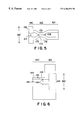
- FIG. 6 is a cross-section of the locking mount of the embodiment shown in FIG. 3;
- FIG. 7 is a cross-section of the valve seating mount of the embodiment shown in FIG. 3;
- FIG. 8 is a cross-section of the distal housing of the embodiment shown in FIG. 3;
- FIG. 9 is a cross-section of a fourth embodiment of the device of the present invention with a sliding seal and integral friction lock;
- FIG. 10 is a cross-section of a fifth embodiment of the device of the present invention with a longitudinally sliding seal
- FIG. 11 is a cross-section of a sixth embodiment of the device of the present invention with a trumpet valve
- FIG. 12 is a cross-section of the embodiment shown in FIG. 11 with the needle inserted;
- FIG. 13 is a cross-section of a fifth embodiment of the device of the present invention with an inflatable seal.
- FIG. 14 is a cross-section of a preferred needle and obturator assembly.
- the present invention comprises a modified catheter 2 (which may be situated subcutaneously, as indicated by skin line 1 ) having an access segment 4 , a distal segment 6 , and an integral valve segment 8 disposed therebetween.
- Modified catheter 2 has throughout most of its length a standard inner diameter 10 and a standard outer diameter 12 . However, there are several distinct deviations from these values in order to achieve the functional purposes of the invention.
- Access segment 4 has disposed at its terminal end a raised identification ring 14 that enable an operator to locate the subcutaneous access device entrance 16 .
- Access segment 4 has an inwardly directed conical access guidance portion 18 and an access alignment portion 20 .
- Access guidance portion 18 has an initial inner diameter 22 greater than standard valve inner diameter 10 that gradually tapers inwardly until standard valve inner diameter 10 is achieved.
- conical access guidance portion 18 guides the percutaneous mating needle 40 into the access alignment portion 20 , where the needle 40 having needle end 48 is aligned with valve slit 28 .
- Needle 40 has an outer barrel diameter 50 , compatible with standard valve inner diameter 10 , and an inner barrel diameter 54 .
- Needle 40 is provided with an obturator 42 having a conical tip for percutaneous insertion of needle 40 into the device without tissue becoming lodged in the lumen of needle 40 .
- Integral valve segment 8 comprises a tapered valve access portion 24 and a valve portal 26 to further align needle 40 with valve slit 28 . It is important to note that integral valve segment 8 is most preferably molded with a solid valve seal portion 30 , which has valve slit 28 later formed therethrough. This construction results in a more complete seal and requires less sealing force than does a flattened tube, as is used in the art.
- Integral valve segment 8 further comprises an opposing tapered distal portion 32 and has formed into its exterior, in radial alignment with valve seal portion 30 , a valve sealing means seat 34 , which is a circumferential depression in the segment exterior such that the catheter outer diameter through valve sealing means seat 34 is less than the standard outer diameter 12 , but greater than standard inner diameter 10 .
- Valve sealing means seat 34 accommodates valve sealing means 36 , which provides a radial biasing force sufficient to close valve seal portion 30 , and keep it closed while the device is not in use.
- valve sealing means 36 may have one or more mounting tabs 38 formed therefrom or attached thereto. During implantation, the one or more mounting tabs 38 are attached to surrounding tissue such that catheter 2 is immobilized throughout integral valve segment 8 , but allows lateral movement of access segment 4 under the skin.
- Outflow segment 6 is implanted such that its terminal end is disposed within the vessel or space to which access is desired.
- an operator first locates access segment 4 through the skin using raised identification ring 14 as a guide. The operator punctures the skin with obturator 42 disposed within needle 40 such that the needle-obturator assembly enters access guidance portion 18 and is aligned by access alignment portion 20 . Continuing to be inserted into the device, the needle-obturator assembly encounters valve access portion 24 and valve portal 26 .
- valve portal 26 As the tip of obturator 42 enters valve portal 26 , the tapered leading edge of obturator 42 presses against valve access portion 24 , overcoming the radical biasing force exerted by valve sealing means 36 and thereby opening valve slit 28 such that needle 40 may pass through the valve seal portion 30 . This is accomplished without damage to valve seal portion 30 because needle 40 has already been axially aligned with valve slit 28 by the access alignment portion 20 . It is understood that this process is much smoother and causes less discomfort to the patient when the needle is provided with a medically acceptable, water-based lubricant prior to insertion.
- valve segment 8 is formed in a closed fashion and valve slit 28 later opened, and also because of the sealing properties of the material from which catheter 2 is made, the valve of the present invention achieves a complete seal with minimal biasing forces required to be exerted by valve sealing means 36 . Accordingly, the force that must be imparted by the needle/obturator combination in order to overcome this biasing force to allow entry of the needle/obturator combination into the valve is substantially less than would be required to close known valves, which are essentially flattened tubes and which never achieve a complete seal, unless substantially greater biasing forces are used. This diminution of force results in less jarring of the device during needle insertion and withdrawal, thereby greatly enhancing patient comfort.
- distal segment 6 is attached to a standard medical catheter 44 by insertion therebetween of adapter 56 .
- Adapter 56 has a first end, disposed within distal segment 6 , and a second end, disposed within catheter 44 , tapered such that the streamlined flowpath is minimally disturbed.
- adapter 56 has formed within its first end a needle seating region 58 having an inner diameter 50 ′ that corresponds with outer barrel diameter 50 of needle 40 .
- Needle seat 58 a extends radially inwardly such that its inner diameter 54 ′ corresponds with inner barrel diameter 54 of needle 40 .
- needle 40 when the needle-obturator assembly is inserted into the device and axially through the seal, needle 40 will seat against needle seat 58 a such that the streamlined flowpath is minimally disturbed, if at all. (See FIG. 1, not shown in FIG. 2 ).
- an implanted access device 100 rests below the skin line 1 .
- the access device 100 comprises an assembly of guidance housing 102 , locking mount 104 , valve 106 , valve seating mount 108 , valve sealing means 120 , adapter 220 , catheter 240 , and distal housing 110 , all arranged about axis AA′.
- the flowpath through the device shown as Axis AA′, is capable of accommodating gentle changes in flow direction.
- a gentle change in flow direction include a bend angle exceeding about 30 degrees, and preferably not exceeding 20 degrees, within a bending radius of less than about two times standard inner diameter 10 . More preferably, such gentle change in flow direction is about 20 degrees within a bending radius of at least about four times standard inner diameter 10 .
- Standard inner diameter 10 is typically between about 0.060 and about 0.105 inch.
- Guidance housing 102 is a modified hollow cylinder having a partially closed first end formed into an inwardly directed conical needle guidance surface 122 that defines an axial access lumen 123 sized to accommodate a needle suitable for use in hemodialysis, plasmapheresis, and fluid exchange therapies.
- Guidance housing 102 has an open second end provided with a chamfered leading edge 124 .
- Locking mount 104 defines lumen 143 capable of accommodating a needle suitable for use in hemodialysis, plasmapheresis, and fluid exchange therapies formed therethrough.
- Locking mount 104 comprises a locking portion 140 , having lock surface 144 with lock lumen 145 formed therein such that lock lumen 145 communicates with lumen 143 , and a valve mounting portion 142 , having formed therein valve seat 146 with cross-sectional diameter 146 ′.
- Locking portion 140 has attached thereto lock biasing means 152 such that lock biasing means 152 movably covers lock lumen 145 .
- Locking means 150 is disposed within lock lumen 145 and is biased toward lumen 143 by lock biasing means 152 .
- Valve 106 has an access segment 160 , a distal segment 164 , and an integral valve segment 162 disposed therebetween.
- Access segment 160 has disposed at its terminal end a raised seating ring 166 having an outer cross-sectional diameter 166 ′ and defining valve entrance 163 .
- Integral valve segment 162 comprises a tapered valve access portion 170 and, optionally, a valve portal 172 to further align needle 40 with valve slit 178 .
- Integral valve segment 162 further comprises an opposing tapered distal portion 174 . It is important to note that integral valve segment 162 is most preferably molded with a solid valve sealing portion 176 , which has valve slit 178 later formed therethrough. This construction results in a more complete seal and requires less sealing force than does a flattened tube, as is used in the art.
- Valve seating mount 108 is a disk-shaped member having an outer cross-sectional diameter 108 ′, a first side oriented toward valve access segment 160 , and a second side oriented toward valve distal segment 164 .
- Valve seating mount 108 defines seating mount lumen 183 having a cross-sectional diameter 183 ′ capable of accommodating valve 106 .
- the first side of seating mount 108 has a circumferential groove 186 disposed just axially of its outer peripheral edge.
- the first side of seating mount 108 also has a raised valve seating spacer 182 formed thereon.
- Valve seating spacer 182 has an outer cross-sectional diameter 182 ′ substantially similar to valve seating ring cross-sectional diameter 166 ′.
- valve seating spacer 182 and valve access ring 166 have substantially the same cross-sectional diameter and matingly fit recessed valve seat 146 in locking mount 104 .
- This construction further prevents undesirable lateral movement of seating mount 108 relative to locking mount 104 , thereby enhancing the stability of access device 100 and minimizing patient discomfort.
- the second side of seating mount 108 has disposed about its outer peripheral edge a raised valve sealing means spacer 184 of sufficient axial thickness to optimally position valve sealing means 120 relative to valve sealing portion 176 .
- Valve sealing means 120 may be any conventional or suitable sealing means capable of exerting a radial sealing force sufficient to seal valve slit 178 , similar to valve slit 28 of FIG. 1 .
- Adapter 220 has a first end, disposed within distal segment 164 , and a second end, disposed within catheter 240 , tapered such that the streamlined flowpath is minimally disturbed.
- adapter 220 has formed within its first end a needle seating region 226 having an inner diameter 50 ′ that corresponds with outer barrel diameter 50 of needle 40 .
- Needle seat 228 extends radially inwardly such that its inner diameter 54 ′ corresponds with inner barrel diameter 54 of needle 40 .
- needle 40 will seat against needle seat 228 such that the streamlined flow path is minimally disturbed, if at all.
- Catheter 240 may be of a type typical of those used in hemodialysis, plasmapheresis, and fluid exchange therapies.
- Distal housing 110 has a first end with an inner cross-sectional diameter 110 ′ sufficient to accommodate valve seating mount 108 having an outer cross-sectional diameter 108 ′.
- first end of distal housing 110 has formed therein valve sealing means retainer 112 capable of optimally positioning valve sealing means 120 relative to valve sealing portion 176 .
- Distal housing 110 further has a second end having formed therethrough a lumen 113 capable of accommodating catheter 240 .
- the cross-section of the needle 40 includes a locking groove 44 .
- locking means 150 extends into locking groove 44 to lock the needle 40 in position.
- the force exerted by lock biasing means 152 on locking means 150 is designed to allow a firm pull to disengage the locking groove 44 from the locking means 150 .
- locking groove 44 is discontinuous around the circumference of the needle, and disengagement of locking means 150 from locking groove 44 is accomplished by rotating the needle 40 and then withdrawing the needle 40 .
- the needle 40 can be from 15 to 17 gauge. In such operation the pressure drop through the needle 40 should not exceed 250 mm Hg. Under these conditions a needle 40 can be made of stainless steel and have a wall thickness of approximately 0.1 mm, thereby providing sufficient strength with high safety factors. In contrast, the use of flexible materials would require a needle wall thickness three to five times greater in order to prevent buckling and collapse during insertion.
- valve 106 is disposed within lumen 183 of valve seating mount 108 , the combination being seated against locking mount 104 , as described above, which combination in turn is entirely disposed within guidance housing 102 .
- Chamfered leading edge 124 of guidance housing 102 matingly fits circumferential groove 186 disposed just axially of the outer peripheral edge of valve seating mount 108 .
- Guidance housing 102 is attached to valve seating mount 108 by known means in order to create a fluid-tight seal.
- Valve sealing means 120 is optimally positioned by valve sealing means spacer 184 and valve sealing means retainer 112 to seal valve sealing portion 176 .
- Adapter 220 is disposed partly within valve distal segment 144 and partly within catheter 240 , as described above.
- Adapter 220 has needle seating region 226 that matingly fits within needle 40 , thereby creating a smooth flowpath from the lumen of needle 40 to catheter 240 .
- Valve 106 , valve seating mount 108 , valve sealing means 120 , adapter 220 , and catheter 240 are all disposed within distal housing 110 .
- Catheter 240 emerges from distal housing 110 via axial lumen 113 formed therethrough.
- FIG. 4 shows an assembled access device 100 , with needle 40 inserted and obturator 42 removed from needle 40 .
- the needle end 48 is in contact with needle seat 228 of adapter 220 , such that the transition from the inner lumen of needle 40 to the inner lumen of adapter 220 is smooth.
- the assembly is designed and constructed such that all the flow diameter changes are gradual and continuous. The angles of these transitions are less than 25 degrees, with less than 10 degrees preferred.
- flow diameter is defined as the diameter of any conduit with fluid flowing measured normal to the flow.
- the cross-section of the needle 40 includes a ridge and locking groove 44 .
- the locking groove 44 is discontinuous around the circumference of the needle, and disengagement of the locking means 150 from the locking groove 44 is accomplished by rotating the needle 40 and then withdrawing the needle 40 from device 100 .
- the locking groove 44 is continuous around the circumference of the needle. The force exerted by lock biasing means 152 on locking means 150 allows the needle 40 to be withdrawn from device 100 with a firm pull to disengage the locking groove 44 from the locking means 150 .
- catheter 240 has formed therefrom or attached thereto one or more tabs 246 with a through hole 248 . These tabs 246 are used to fix the catheter 240 , by tying or suturing, to the surrounding tissue upon implantation of device 100 .
- the device 100 itself is not fixed to the surrounding tissue. With this arrangement, the device 100 can move underneath the skin enough to align with a needle 40 penetrating the skin without having the needle 40 move transversely to the skin. Adhesions from the tissue to the device 100 are discouraged by treating the housing surface with hyaluronic acid.
- the device can, if desired, also incorporate, or have its exterior surfaces treated with, antibacterial material.
- FIG. 9 shows another contemplated embodiment 300 where there is an integral friction lock to secure the needle 40 within the access device 300 .
- a sealing plug 304 is disposed within housing assembly 302 / 310 between its access lumen 303 and the biasing force transmission flange 309 of piston 308 .
- spring 306 biases piston 308 against sealing plug 304 , urging sealing plug 304 against tapered sealing surface 344 , thereby preventing fluid flow through the device.
- the needle 40 is guided to the access lumen 303 by the conical needle guidance surface 322 of guidance housing 302 , wherein needle 40 contacts sealing plug 304 .
- the axial force exerted by needle 40 on the sealing plug 304 overcomes the sealing plug biasing force exerted on the biasing force transmission flange 309 of piston 308 by spring 306 , moving sealing plug 304 away from sealing surface 344 and removing the radial compressive forces normally exerted on the sealing plug 304 , sufficiently to allow needle 40 to puncture sealing plug 304 .
- sealing plug 304 consistently is punctured in the same place and direction due to guidance of the needle 40 by the conical needle guidance surface 322 of guidance housing 302 . This feature effectively eliminates sealing plug fragmentation.
- sealing plug 304 provides enough residual pressure onto the needle 40 to effectively lock the needle 40 into the device 300 .
- An axial pull on the needle 40 tends to pull the sealing plug 304 against the sealing surface 344 , increasing the radial forces exerted on the needle 40 , thereby holding the needle 40 even more securely.
- a simple twist of needle 40 introduces dynamic friction and allows the needle 40 to be removed from the device.
- O-rings 312 and 314 seal the needle 40 from the piston 308 and the piston 308 from the sealing housing 310 , respectively.
- spring 306 biases the piston 308 towards the skin line 1 , compressing the sealing plug 304 such that the sealing plug 304 seals itself, closing the passageway formed by insertion of needle 40 . Note that, as the piston 308 slides relative to the catheter 340 and the sealing housing 310 , the transition from the piston 308 and the catheter 340 inner wall and/or the sealing housing 310 inner wall remains smooth.
- FIG. 10 is yet another contemplated valving for the present invention.
- the needle 40 contacts a sliding spring-loaded poppet 404 .
- the valve structure 408 is biased away from guidance housing 402 (as shown).
- the O-ring 416 leaves the housing wall 405 allowing fluid to pass through the valve.
- Spring 406 forces the poppet 404 and O-ring 416 back into contact with the housing wall 405 when the needle 40 is extracted from the device.
- the poppet 404 does not extend throughout the valve circumference, as it would then interfere with the fluid flow.
- the poppet 404 has a plurality of rod-like extensions 418 that provide open areas for fluid to pass through the valve when the needle 40 is inserted.
- the O-ring 406 provides a seal to prevent leakage around the needle 40 .
- FIGS. 11 and 12 show another contemplated embodiment 500 , wherein the valve sealing means is a trumpet valve 504 .
- the valve sealing means is a trumpet valve 504 .
- a fine needle 509 may be percutaneously introduced into lumen 530 and penetrate the septum 512 to open valve 504 by injecting fluid into reservoir 520 sufficient to overcome the biasing force exerted by spring 508 .
- Needle 40 may then be introduced into the device 500 , in a similar manner as described above with respect to 300 (FIG. 9) and 400 (FIG. 10 ), and guidance housing 502 having conical needle guidance surface 522 guides needle 40 .
- needle 40 is removed from the device and a trumpet valve 504 is closed by withdrawing fluid from reservoir 520 via fine needle 509 , which is then removed from the device.
- a sealing housing 510 which cooperates with guidance housing 502 and there is a seal 504 which seals passageway 503 .
- FIG. 13 is another contemplated embodiment 600 where an inflatable seal 604 seals passageway 603 .
- the needle 40 guided by a conical needle guidance surface 522 of guidance housing 502 , pushes the expandable seal 604 apart when inserted.
- the needle 40 hits the stop 608 built into the sealing housing 610 .
- the seal 604 expands, closing the passageway 603 .
- a fine needle 609 may be percutaneously introduced into lumen 630 and penetrate the septum 612 to reexpand the seal 604 by injecting fluid into reservoir 620 , which is in fluid connection with the lumen of seal 604 .
- the flowpath transition from the sealing housing 610 to the catheter 640 is smooth.
- FIG. 14 shows a preferred corresponding needle assembly constructed and arranged to mate with the previously described implanted access housings.
- the needle barrel 40 is of a thin metal material. Thinner material maximizes the actual flow diameter which is a general goal of any hemodialysis needle. The discomfort to the patient is reduced by smaller diameter needles, but such needles restrict flow or provide large pressure drops when high flows are forced through small needles. Low flowrates would require inordinate treatment time for hemodialysis, and high flowrates through narrow needles damage blood. There is a tradeoff and thin needle walls contribute to maximized flow diameters for a given outer needle diameter.
- An obturator 42 is fitted within the needle 40 , providing a smooth transition 43 between the outer surface of needle 40 at the needle tip 48 and the obturator 42 .
- the barrel of needle 40 has a semi-circular locking groove 44 A.
- the obturator 42 is secured to a housing 68 via threads 62 .
- the obturator 42 is necessary since the needle 40 is hollow and cannot be used to penetrate the skin because its large diameter lumen will become plugged.
- the obturator 42 exactly fills the hollow face presented to the skin and has a point 45 suitable for penetrating the skin.
- the housing 68 provides a channel 69 with the threaded fitting 64 for connecting to the hemodialysis equipment.
Abstract
Description
Claims (40)
Priority Applications (4)
| Application Number | Priority Date | Filing Date | Title |
|---|---|---|---|
| US09/083,078 US6206851B1 (en) | 1995-06-07 | 1998-05-21 | Hemodialysis access apparatus |
| PCT/US1999/011183 WO2000016834A1 (en) | 1998-05-21 | 1999-05-20 | Hemodialysis access apparatus |
| EP99924398A EP1079880A4 (en) | 1998-05-21 | 1999-05-20 | Hemodialysis access apparatus |
| AU40907/99A AU4090799A (en) | 1998-05-21 | 1999-05-20 | Hemodialysis access apparatus |
Applications Claiming Priority (2)
| Application Number | Priority Date | Filing Date | Title |
|---|---|---|---|
| US08/485,498 US5954691A (en) | 1995-06-07 | 1995-06-07 | Hemodialysis access apparatus |
| US09/083,078 US6206851B1 (en) | 1995-06-07 | 1998-05-21 | Hemodialysis access apparatus |
Related Parent Applications (1)
| Application Number | Title | Priority Date | Filing Date |
|---|---|---|---|
| US08/485,498 Continuation-In-Part US5954691A (en) | 1995-06-07 | 1995-06-07 | Hemodialysis access apparatus |
Publications (1)
| Publication Number | Publication Date |
|---|---|
| US6206851B1 true US6206851B1 (en) | 2001-03-27 |
Family
ID=22176035
Family Applications (1)
| Application Number | Title | Priority Date | Filing Date |
|---|---|---|---|
| US09/083,078 Expired - Fee Related US6206851B1 (en) | 1995-06-07 | 1998-05-21 | Hemodialysis access apparatus |
Country Status (4)
| Country | Link |
|---|---|
| US (1) | US6206851B1 (en) |
| EP (1) | EP1079880A4 (en) |
| AU (1) | AU4090799A (en) |
| WO (1) | WO2000016834A1 (en) |
Cited By (52)
| Publication number | Priority date | Publication date | Assignee | Title |
|---|---|---|---|---|
| EP1245247A1 (en) * | 2001-03-28 | 2002-10-02 | Biolink Corporation | Biocidal locks |
| WO2002096495A2 (en) * | 2001-05-25 | 2002-12-05 | Becton Dickinson And Company | Catheter having a low drag septum |
| US20020193752A1 (en) * | 1994-04-22 | 2002-12-19 | Lynn Lawrence A. | Medical valve |
| US6679870B1 (en) | 1999-07-23 | 2004-01-20 | Vasca, Inc. | Methods and kits for locking and disinfecting implanted catheters |
| US6685694B2 (en) | 1999-07-23 | 2004-02-03 | Vasca, Inc. | Methods and kits for locking and disinfecting implanted catheters |
| US20040204689A1 (en) * | 2000-08-14 | 2004-10-14 | Lynn Lawrence A. | Catheter and needle assembly with dual sealing |
| WO2005018732A1 (en) * | 2003-08-26 | 2005-03-03 | Zerusa Limited | A haemostasis device |
| US20050267445A1 (en) * | 2002-11-19 | 2005-12-01 | Biometrix Ltd. | Manifold hub for patient fluid administration |
| US20060047249A1 (en) * | 2004-08-31 | 2006-03-02 | Igor Shubayev | Percutaneous vascular access device |
| US20070093778A1 (en) * | 2005-10-25 | 2007-04-26 | Chris Cindrich | One piece low drag septum |
| US20070112305A1 (en) * | 2005-11-15 | 2007-05-17 | Becton Dickinson And Company | Needle shield to septum interconnect |
| US20070191779A1 (en) * | 2004-08-31 | 2007-08-16 | Igor Shubayev | Percutaneous Vascular Access Device With External Disposable Connector |
| US20080147012A1 (en) * | 2004-05-12 | 2008-06-19 | C.R.Bard, Inc. | Catheter with Removable Extension |
| US20080195060A1 (en) * | 2007-02-09 | 2008-08-14 | Baxter International Inc. | Optical access disconnection systems and methods |
| US20080195021A1 (en) * | 2007-02-09 | 2008-08-14 | Baxter International Inc. | Acoustic access disconnection systems and methods |
| CN100430105C (en) * | 2002-04-01 | 2008-11-05 | Nd合伙人股份有限公司 | Method and device for preventing infection in tissue bag around implantation aapliance |
| WO2009033177A1 (en) * | 2007-09-07 | 2009-03-12 | Imtec, Llc | Method and device for dialysis |
| US20100152640A1 (en) * | 2008-09-05 | 2010-06-17 | Imtecbiomedical, Inc. | Methods and apparatus for vascular access |
| US20100174243A1 (en) * | 2009-01-05 | 2010-07-08 | Warsaw Orthopedic, Inc. | Apparatus for Delivery of Therapeutic Material to an Intervertebral Disc and Method of Use |
| US8114043B2 (en) | 2008-07-25 | 2012-02-14 | Baxter International Inc. | Electromagnetic induction access disconnect sensor |
| US8177760B2 (en) | 2004-05-12 | 2012-05-15 | C. R. Bard, Inc. | Valved connector |
| US8529490B2 (en) | 2002-04-10 | 2013-09-10 | Baxter International Inc. | Systems and methods for dialysis access disconnection |
| US8708946B2 (en) | 2002-04-10 | 2014-04-29 | Baxter International Inc. | Access disconnection systems using conductive contacts |
| US8920356B2 (en) | 2002-04-10 | 2014-12-30 | Baxter International Inc. | Conductive polymer materials and applications thereof including monitoring and providing effective therapy |
| US9074920B2 (en) | 2009-06-03 | 2015-07-07 | Biometrix Ltd. | Apparatus and method for bedside collection of body fluids and automatic volume level monitoring |
| US9138536B2 (en) | 2008-04-01 | 2015-09-22 | Gambro Lundia Ab | Apparatus and a method for monitoring a vascular access |
| US9295773B2 (en) | 2010-11-09 | 2016-03-29 | Frank Prosl | Hemodialysis access system |
| US9357950B2 (en) | 2009-06-03 | 2016-06-07 | Biometrix Ltd. | Apparatus and method of fluid aspiration |
| US9700677B2 (en) | 2006-06-22 | 2017-07-11 | Excelsior Medical Corporation | Antiseptic cap with antiseptic |
| USD819802S1 (en) | 2016-10-05 | 2018-06-05 | Becton, Dickinson And Company | Catheter adapter |
| US20180280676A1 (en) * | 2017-03-30 | 2018-10-04 | Pfm Medical Ag | Implantable access device for accessing the vascular system of a human or animal body |
| USD835262S1 (en) | 2016-10-05 | 2018-12-04 | Becton, Dickinson And Company | Intravenous catheter assembly |
| US10155082B2 (en) | 2002-04-10 | 2018-12-18 | Baxter International Inc. | Enhanced signal detection for access disconnection systems |
| USD837368S1 (en) | 2016-10-05 | 2019-01-01 | Becton, Dickinson And Company | Catheter adapter grip |
| WO2019055813A1 (en) | 2017-09-14 | 2019-03-21 | Okundaye Clifford | Dialysis catheter |
| US10238852B2 (en) | 2016-10-05 | 2019-03-26 | Becton, Dickinson And Company | Septum housing |
| USD844781S1 (en) | 2016-10-05 | 2019-04-02 | Becton, Dickinson And Company | Needle hub |
| US10245416B2 (en) | 2015-10-28 | 2019-04-02 | Becton, Dickinson And Company | Intravenous catheter device with integrated extension tube |
| US10357636B2 (en) | 2015-10-28 | 2019-07-23 | Becton, Dickinson And Company | IV access device having an angled paddle grip |
| US10463845B2 (en) | 2013-01-23 | 2019-11-05 | C.R. Bard, Inc. | Low-profile access port |
| US10463778B2 (en) | 2007-02-09 | 2019-11-05 | Baxter International Inc. | Blood treatment machine having electrical heartbeat analysis |
| USD870264S1 (en) | 2017-09-06 | 2019-12-17 | C. R. Bard, Inc. | Implantable apheresis port |
| WO2019245820A1 (en) * | 2018-06-19 | 2019-12-26 | Aadi Innovations LLC | Vascular access catheter with protectable inline needle and associated method of use thereof |
| US10525237B2 (en) | 2015-10-28 | 2020-01-07 | Becton, Dickinson And Company | Ergonomic IV systems and methods |
| US10549072B2 (en) | 2015-10-28 | 2020-02-04 | Becton, Dickinson And Company | Integrated catheter with independent fluid paths |
| CN111093731A (en) * | 2017-09-14 | 2020-05-01 | 西托索尔本茨公司 | Connector assembly and method of use |
| US10639455B2 (en) | 2015-10-28 | 2020-05-05 | Becton, Dickinson And Company | Closed IV access device with paddle grip needle hub and flash chamber |
| US10744305B2 (en) | 2015-10-28 | 2020-08-18 | Becton, Dickinson And Company | Ergonomic IV systems and methods |
| US10814106B2 (en) | 2015-10-28 | 2020-10-27 | Becton, Dickinson And Company | Soft push tabs for catheter adapter |
| US11420033B2 (en) | 2013-01-23 | 2022-08-23 | C. R. Bard, Inc. | Low-profile single and dual vascular access device |
| US11464960B2 (en) | 2013-01-23 | 2022-10-11 | C. R. Bard, Inc. | Low-profile single and dual vascular access device |
| US11951266B2 (en) | 2017-03-09 | 2024-04-09 | Becton, Dickinson And Company | Intravenous catheter assembly with cannula safety mechanism |
Families Citing this family (3)
| Publication number | Priority date | Publication date | Assignee | Title |
|---|---|---|---|---|
| US20040178586A1 (en) * | 2003-02-20 | 2004-09-16 | Biotronik Gmbh & Co. Kg | Sealing element |
| EP3329957A1 (en) * | 2016-12-01 | 2018-06-06 | Delta Med S.p.A. | Intravenous catheter with blood stop feature |
| CN112156253A (en) * | 2020-08-31 | 2021-01-01 | 陈楠 | Nephrology department dialysis tube fixing device |
Citations (1)
| Publication number | Priority date | Publication date | Assignee | Title |
|---|---|---|---|---|
| US5741228A (en) * | 1995-02-17 | 1998-04-21 | Strato/Infusaid | Implantable access device |
Family Cites Families (6)
| Publication number | Priority date | Publication date | Assignee | Title |
|---|---|---|---|---|
| US4822341A (en) * | 1987-11-20 | 1989-04-18 | Impra, Inc. | Vascular access fistula |
| US5281199A (en) | 1990-03-01 | 1994-01-25 | Michigan Transtech Corporation | Implantable access devices |
| US5226879A (en) | 1990-03-01 | 1993-07-13 | William D. Ensminger | Implantable access device |
| US5263930A (en) | 1990-03-01 | 1993-11-23 | William D. Ensminger | Implantable access devices |
| US5180365A (en) | 1990-03-01 | 1993-01-19 | Ensminger William D | Implantable infusion device |
| US6013058A (en) * | 1996-06-12 | 2000-01-11 | Biolink Corporation | Device for subcutaneous accessibility |
-
1998
- 1998-05-21 US US09/083,078 patent/US6206851B1/en not_active Expired - Fee Related
-
1999
- 1999-05-20 EP EP99924398A patent/EP1079880A4/en not_active Withdrawn
- 1999-05-20 AU AU40907/99A patent/AU4090799A/en not_active Abandoned
- 1999-05-20 WO PCT/US1999/011183 patent/WO2000016834A1/en active Application Filing
Patent Citations (1)
| Publication number | Priority date | Publication date | Assignee | Title |
|---|---|---|---|---|
| US5741228A (en) * | 1995-02-17 | 1998-04-21 | Strato/Infusaid | Implantable access device |
Cited By (101)
| Publication number | Priority date | Publication date | Assignee | Title |
|---|---|---|---|---|
| US20020193752A1 (en) * | 1994-04-22 | 2002-12-19 | Lynn Lawrence A. | Medical valve |
| US20080048144A1 (en) * | 1998-05-29 | 2008-02-28 | Lynn Lawrence A | Luer Receiver and Method for Fluid Transfer |
| US7998122B2 (en) | 1998-05-29 | 2011-08-16 | Becton, Dickinson & Company | Luer receiver and method for fluid transfer |
| US20080051733A1 (en) * | 1998-05-29 | 2008-02-28 | Lynn Lawrence A | Luer Receiver and Method for Fluid Transfer |
| US8475416B2 (en) | 1998-05-29 | 2013-07-02 | Lawrence A. Lynn | Luer receiver and method for fluid transfer |
| US8808254B2 (en) | 1998-05-29 | 2014-08-19 | Becton Dickinson And Company | Luer receiver and method for fluid transfer |
| US20080108956A1 (en) * | 1998-05-29 | 2008-05-08 | Lynn Lawrence A | Luer Receiver and Method for Fluid Transfer |
| US20060129112A1 (en) * | 1998-05-29 | 2006-06-15 | Lynn Lawrence A | Luer receiver and method for fluid transfer |
| US8403894B2 (en) | 1998-05-29 | 2013-03-26 | Becton, Dickinson and Company (partial interest) | Luer receiver and method for fluid transfer |
| US6685694B2 (en) | 1999-07-23 | 2004-02-03 | Vasca, Inc. | Methods and kits for locking and disinfecting implanted catheters |
| US6679870B1 (en) | 1999-07-23 | 2004-01-20 | Vasca, Inc. | Methods and kits for locking and disinfecting implanted catheters |
| US20040204689A1 (en) * | 2000-08-14 | 2004-10-14 | Lynn Lawrence A. | Catheter and needle assembly with dual sealing |
| EP1245247A1 (en) * | 2001-03-28 | 2002-10-02 | Biolink Corporation | Biocidal locks |
| WO2002096495A2 (en) * | 2001-05-25 | 2002-12-05 | Becton Dickinson And Company | Catheter having a low drag septum |
| CN101618248B (en) * | 2001-05-25 | 2012-12-05 | 贝克顿迪肯森公司 | Catheter having a low drag septum |
| US6719726B2 (en) | 2001-05-25 | 2004-04-13 | Becton Dickinson And Company | Catheter having a low drag septum |
| WO2002096495A3 (en) * | 2001-05-25 | 2003-03-13 | Becton Dickinson Co | Catheter having a low drag septum |
| US6506181B2 (en) | 2001-05-25 | 2003-01-14 | Becton, Dickinson And Company | Catheter having a low drag septum |
| CN101461982B (en) * | 2002-04-01 | 2012-06-27 | Nd合伙人股份有限公司 | Device for overcoming infection contamination in tissue bag surrounding implantation instrument |
| CN100430105C (en) * | 2002-04-01 | 2008-11-05 | Nd合伙人股份有限公司 | Method and device for preventing infection in tissue bag around implantation aapliance |
| US10155082B2 (en) | 2002-04-10 | 2018-12-18 | Baxter International Inc. | Enhanced signal detection for access disconnection systems |
| US8801646B2 (en) | 2002-04-10 | 2014-08-12 | Baxter International Inc. | Access disconnection systems with arterial and venous line conductive pathway |
| US8920356B2 (en) | 2002-04-10 | 2014-12-30 | Baxter International Inc. | Conductive polymer materials and applications thereof including monitoring and providing effective therapy |
| US8708946B2 (en) | 2002-04-10 | 2014-04-29 | Baxter International Inc. | Access disconnection systems using conductive contacts |
| US8529490B2 (en) | 2002-04-10 | 2013-09-10 | Baxter International Inc. | Systems and methods for dialysis access disconnection |
| US20050267445A1 (en) * | 2002-11-19 | 2005-12-01 | Biometrix Ltd. | Manifold hub for patient fluid administration |
| US8361011B2 (en) | 2002-11-19 | 2013-01-29 | Biometrix Ltd. | Manifold hub for patient fluid administration |
| US20100022967A1 (en) * | 2002-11-19 | 2010-01-28 | Biometrix Ltd. | Manifold hub for patient fluid administration |
| US8034021B2 (en) | 2002-11-19 | 2011-10-11 | Biometrix Ltd. | Manifold hub for patient fluid administration |
| US7563243B2 (en) | 2002-11-19 | 2009-07-21 | Biometrix Ltd. | Manifold hub for patient fluid administration |
| US7976503B2 (en) | 2003-08-26 | 2011-07-12 | Vascular Solutions Zerusa Limited | Haemostasis device |
| WO2005018732A1 (en) * | 2003-08-26 | 2005-03-03 | Zerusa Limited | A haemostasis device |
| US20050085789A1 (en) * | 2003-08-26 | 2005-04-21 | Khan Mazhar M. | Haemostasis device |
| US20080147012A1 (en) * | 2004-05-12 | 2008-06-19 | C.R.Bard, Inc. | Catheter with Removable Extension |
| US8177760B2 (en) | 2004-05-12 | 2012-05-15 | C. R. Bard, Inc. | Valved connector |
| US7223257B2 (en) | 2004-08-31 | 2007-05-29 | Igor Shubayev | Percutaneous vascular access device |
| US20060047249A1 (en) * | 2004-08-31 | 2006-03-02 | Igor Shubayev | Percutaneous vascular access device |
| US20070191779A1 (en) * | 2004-08-31 | 2007-08-16 | Igor Shubayev | Percutaneous Vascular Access Device With External Disposable Connector |
| US8066675B2 (en) | 2005-10-25 | 2011-11-29 | Becton, Dickinson And Company | One piece low drag septum |
| US20070093778A1 (en) * | 2005-10-25 | 2007-04-26 | Chris Cindrich | One piece low drag septum |
| US20100168675A1 (en) * | 2005-10-25 | 2010-07-01 | Becton, Dickinson And Company | One piece low drag septum |
| US7670317B2 (en) | 2005-10-25 | 2010-03-02 | Becton, Dickinson And Company | One piece low drag septum |
| US20070112305A1 (en) * | 2005-11-15 | 2007-05-17 | Becton Dickinson And Company | Needle shield to septum interconnect |
| US7798994B2 (en) | 2005-11-15 | 2010-09-21 | Becton, Dickinson And Company | Needle shield to septum interconnect |
| US9700677B2 (en) | 2006-06-22 | 2017-07-11 | Excelsior Medical Corporation | Antiseptic cap with antiseptic |
| US8603020B2 (en) | 2007-02-09 | 2013-12-10 | Baxter International Inc. | Ultrasound access disconnection systems and methods |
| US9089654B2 (en) | 2007-02-09 | 2015-07-28 | Baxter International Inc. | Acoustic access disconnection systems and methods |
| US8152751B2 (en) | 2007-02-09 | 2012-04-10 | Baxter International Inc. | Acoustic access disconnection systems and methods |
| US10463778B2 (en) | 2007-02-09 | 2019-11-05 | Baxter International Inc. | Blood treatment machine having electrical heartbeat analysis |
| US8376978B2 (en) | 2007-02-09 | 2013-02-19 | Baxter International Inc. | Optical access disconnection systems and methods |
| US20080195060A1 (en) * | 2007-02-09 | 2008-08-14 | Baxter International Inc. | Optical access disconnection systems and methods |
| US9950105B2 (en) | 2007-02-09 | 2018-04-24 | Baxter International Inc. | Blood treatment and electrical blood leak detection device therefore |
| US8795217B2 (en) | 2007-02-09 | 2014-08-05 | Baxter International Inc. | Acoustic access disconnection systems and methods |
| US20080195021A1 (en) * | 2007-02-09 | 2008-08-14 | Baxter International Inc. | Acoustic access disconnection systems and methods |
| US9352078B2 (en) | 2007-02-09 | 2016-05-31 | Baxter International Inc. | Electrical heartbeat access disconnection systems |
| US9138528B2 (en) | 2007-02-09 | 2015-09-22 | Baxter International Inc. | Acoustic access disconnection systems and methods |
| US8920355B2 (en) | 2007-02-09 | 2014-12-30 | Baxter International Inc. | Acoustic access disconnection systems and methods |
| US20090209918A1 (en) * | 2007-09-07 | 2009-08-20 | Imtec, Llc | Method and device for dialysis |
| WO2009033177A1 (en) * | 2007-09-07 | 2009-03-12 | Imtec, Llc | Method and device for dialysis |
| US9138536B2 (en) | 2008-04-01 | 2015-09-22 | Gambro Lundia Ab | Apparatus and a method for monitoring a vascular access |
| US8114043B2 (en) | 2008-07-25 | 2012-02-14 | Baxter International Inc. | Electromagnetic induction access disconnect sensor |
| US8632486B2 (en) | 2008-07-25 | 2014-01-21 | Baxter International Inc. | Electromagnetic induction access disconnect systems |
| US20100152640A1 (en) * | 2008-09-05 | 2010-06-17 | Imtecbiomedical, Inc. | Methods and apparatus for vascular access |
| US20100174243A1 (en) * | 2009-01-05 | 2010-07-08 | Warsaw Orthopedic, Inc. | Apparatus for Delivery of Therapeutic Material to an Intervertebral Disc and Method of Use |
| WO2010078406A3 (en) * | 2009-01-05 | 2010-09-30 | Warsaw Orthopedic, Inc. | Apparatus for delivery of therapeutic material to an intervertebral disc and method of use |
| US9074920B2 (en) | 2009-06-03 | 2015-07-07 | Biometrix Ltd. | Apparatus and method for bedside collection of body fluids and automatic volume level monitoring |
| US9357950B2 (en) | 2009-06-03 | 2016-06-07 | Biometrix Ltd. | Apparatus and method of fluid aspiration |
| US9295773B2 (en) | 2010-11-09 | 2016-03-29 | Frank Prosl | Hemodialysis access system |
| US11464960B2 (en) | 2013-01-23 | 2022-10-11 | C. R. Bard, Inc. | Low-profile single and dual vascular access device |
| US11420033B2 (en) | 2013-01-23 | 2022-08-23 | C. R. Bard, Inc. | Low-profile single and dual vascular access device |
| US10463845B2 (en) | 2013-01-23 | 2019-11-05 | C.R. Bard, Inc. | Low-profile access port |
| US11571551B2 (en) | 2015-10-28 | 2023-02-07 | Becton, Dickinson And Company | Ergonomic IV systems and methods |
| US11123523B2 (en) | 2015-10-28 | 2021-09-21 | Becton, Dickinson And Company | Intravenous catheter device with integrated extension tube |
| US10814106B2 (en) | 2015-10-28 | 2020-10-27 | Becton, Dickinson And Company | Soft push tabs for catheter adapter |
| US10744305B2 (en) | 2015-10-28 | 2020-08-18 | Becton, Dickinson And Company | Ergonomic IV systems and methods |
| US11786703B2 (en) | 2015-10-28 | 2023-10-17 | Becton, Dickinson And Company | Closed IV access device with paddle grip needle hub and flash chamber |
| US10245416B2 (en) | 2015-10-28 | 2019-04-02 | Becton, Dickinson And Company | Intravenous catheter device with integrated extension tube |
| US10357636B2 (en) | 2015-10-28 | 2019-07-23 | Becton, Dickinson And Company | IV access device having an angled paddle grip |
| US10525237B2 (en) | 2015-10-28 | 2020-01-07 | Becton, Dickinson And Company | Ergonomic IV systems and methods |
| US10639455B2 (en) | 2015-10-28 | 2020-05-05 | Becton, Dickinson And Company | Closed IV access device with paddle grip needle hub and flash chamber |
| US10549072B2 (en) | 2015-10-28 | 2020-02-04 | Becton, Dickinson And Company | Integrated catheter with independent fluid paths |
| USD888236S1 (en) | 2016-10-05 | 2020-06-23 | Becton, Dickinson And Company | Catheter adapter grip |
| USD837368S1 (en) | 2016-10-05 | 2019-01-01 | Becton, Dickinson And Company | Catheter adapter grip |
| USD835262S1 (en) | 2016-10-05 | 2018-12-04 | Becton, Dickinson And Company | Intravenous catheter assembly |
| USD819802S1 (en) | 2016-10-05 | 2018-06-05 | Becton, Dickinson And Company | Catheter adapter |
| USD844781S1 (en) | 2016-10-05 | 2019-04-02 | Becton, Dickinson And Company | Needle hub |
| US10238852B2 (en) | 2016-10-05 | 2019-03-26 | Becton, Dickinson And Company | Septum housing |
| USD893707S1 (en) | 2016-10-05 | 2020-08-18 | Becton, Dickinson And Company | Intravenous catheter assembly |
| USD900308S1 (en) | 2016-10-05 | 2020-10-27 | Becton, Dickinson And Company | Catheter adapter |
| US11793986B2 (en) | 2016-10-05 | 2023-10-24 | Becton, Dickinson And Company | Septum housing |
| US11951266B2 (en) | 2017-03-09 | 2024-04-09 | Becton, Dickinson And Company | Intravenous catheter assembly with cannula safety mechanism |
| US10940302B2 (en) * | 2017-03-30 | 2021-03-09 | Pfm Medical Ag | Implantable access device for accessing the vascular system of a human or animal body |
| US20180280676A1 (en) * | 2017-03-30 | 2018-10-04 | Pfm Medical Ag | Implantable access device for accessing the vascular system of a human or animal body |
| USD885557S1 (en) | 2017-09-06 | 2020-05-26 | C. R. Bard, Inc. | Implantable apheresis port |
| USD870264S1 (en) | 2017-09-06 | 2019-12-17 | C. R. Bard, Inc. | Implantable apheresis port |
| WO2019055824A2 (en) | 2017-09-14 | 2019-03-21 | Okundaye Clifford | Dialysis catheter |
| WO2019055813A1 (en) | 2017-09-14 | 2019-03-21 | Okundaye Clifford | Dialysis catheter |
| EP3681557A4 (en) * | 2017-09-14 | 2021-06-16 | Okundaye, Clifford | Dialysis catheter |
| EP3682628A4 (en) * | 2017-09-14 | 2021-05-12 | Okundaye, Clifford | Dialysis catheter |
| CN111093731A (en) * | 2017-09-14 | 2020-05-01 | 西托索尔本茨公司 | Connector assembly and method of use |
| WO2019245820A1 (en) * | 2018-06-19 | 2019-12-26 | Aadi Innovations LLC | Vascular access catheter with protectable inline needle and associated method of use thereof |
Also Published As
| Publication number | Publication date |
|---|---|
| WO2000016834A1 (en) | 2000-03-30 |
| AU4090799A (en) | 2000-04-10 |
| EP1079880A1 (en) | 2001-03-07 |
| EP1079880A4 (en) | 2002-01-09 |
Similar Documents
| Publication | Publication Date | Title |
|---|---|---|
| US6206851B1 (en) | Hemodialysis access apparatus | |
| US5954691A (en) | Hemodialysis access apparatus | |
| US5911706A (en) | Device for subcutaneous accessibility | |
| US8506533B2 (en) | Surgical fluid transfer apparatus | |
| EP0968026B1 (en) | Valve port for vascular access | |
| JP2888990B2 (en) | Implantable access device | |
| US6506182B2 (en) | Method for subcutaneous access to the vascular system of a patient | |
| US7854731B2 (en) | Valved catheter | |
| US5456675A (en) | Port cannula arrangement for connection to a port | |
| US7056316B1 (en) | Valve port and method for vascular access | |
| US7094218B2 (en) | Valved catheter | |
| US20090005741A1 (en) | Closable and Openable Catheter Assembly and Method of Using Same | |
| CN110582323B (en) | Implantable access device for accessing the vascular system of a human or animal body | |
| WO2001032141A1 (en) | Valve port and method for vascular access |
Legal Events
| Date | Code | Title | Description |
|---|---|---|---|
| AS | Assignment |
Owner name: BIOLINK CORPORATION, MASSACHUSETTS Free format text: ASSIGNMENT OF ASSIGNORS INTEREST;ASSIGNOR:PROSL, FRANK R.;REEL/FRAME:009195/0497 Effective date: 19980515 |
|
| AS | Assignment |
Owner name: MCKINLAY, THOMAS, AS COLLATERAL AGENT, CALIFORNIA Free format text: SECURITY INTEREST;ASSIGNOR:BIOLINK CORPORATION;REEL/FRAME:012075/0975 Effective date: 20010911 |
|
| AS | Assignment |
Owner name: BIOLINK CORPORATION, MASSACHUSETTS Free format text: TERMINATION OF SECURITY INTEREST;ASSIGNOR:MCKINLEY, THOMAS;REEL/FRAME:013417/0937 Effective date: 20030211 |
|
| AS | Assignment |
Owner name: SPINNAKER CAPITAL LLC, AS AGENT, MASSACHUSETTS Free format text: PATENT COLLATERAL ASSIGNMENT AND SECURITY AGREEMENT;ASSIGNOR:BIOLINK CORPORATION;REEL/FRAME:013791/0714 Effective date: 20030227 |
|
| FPAY | Fee payment |
Year of fee payment: 4 |
|
| AS | Assignment |
Owner name: ND PARTNERS, LLC, MASSACHUSETTS Free format text: ASSIGNMENT OF ASSIGNORS INTEREST;ASSIGNOR:MADOFF, DAVID B., DULY APPOINTED TRUSTEE IN BANKRUPTCY FOR THE DEBTOR BIOLINK CORPORATION IN CASE NO. 03-17076 IN THE UNITED STATES BANKRUPTCY COURT FOR THE DISTRICT OF MASSACHUSETTS, EASTERN DIVISION, HAVING ACQUIRED TITLE THERETO PURSUANT;REEL/FRAME:015293/0289 Effective date: 20041026 |
|
| FEPP | Fee payment procedure |
Free format text: PAYER NUMBER DE-ASSIGNED (ORIGINAL EVENT CODE: RMPN); ENTITY STATUS OF PATENT OWNER: SMALL ENTITY Free format text: PAYOR NUMBER ASSIGNED (ORIGINAL EVENT CODE: ASPN); ENTITY STATUS OF PATENT OWNER: SMALL ENTITY |
|
| FPAY | Fee payment |
Year of fee payment: 8 |
|
| REMI | Maintenance fee reminder mailed | ||
| LAPS | Lapse for failure to pay maintenance fees | ||
| STCH | Information on status: patent discontinuation |
Free format text: PATENT EXPIRED DUE TO NONPAYMENT OF MAINTENANCE FEES UNDER 37 CFR 1.362 |
|
| FP | Lapsed due to failure to pay maintenance fee |
Effective date: 20130327 |