US6210369B1 - Automatic injector - Google Patents
Automatic injector Download PDFInfo
- Publication number
- US6210369B1 US6210369B1 US09/212,570 US21257098A US6210369B1 US 6210369 B1 US6210369 B1 US 6210369B1 US 21257098 A US21257098 A US 21257098A US 6210369 B1 US6210369 B1 US 6210369B1
- Authority
- US
- United States
- Prior art keywords
- needle
- cartridge
- cover
- housing
- actuator
- Prior art date
- Legal status (The legal status is an assumption and is not a legal conclusion. Google has not performed a legal analysis and makes no representation as to the accuracy of the status listed.)
- Expired - Fee Related
Links
Images


Classifications
-
- A—HUMAN NECESSITIES
- A61—MEDICAL OR VETERINARY SCIENCE; HYGIENE
- A61M—DEVICES FOR INTRODUCING MEDIA INTO, OR ONTO, THE BODY; DEVICES FOR TRANSDUCING BODY MEDIA OR FOR TAKING MEDIA FROM THE BODY; DEVICES FOR PRODUCING OR ENDING SLEEP OR STUPOR
- A61M5/00—Devices for bringing media into the body in a subcutaneous, intra-vascular or intramuscular way; Accessories therefor, e.g. filling or cleaning devices, arm-rests
- A61M5/178—Syringes
- A61M5/24—Ampoule syringes, i.e. syringes with needle for use in combination with replaceable ampoules or carpules, e.g. automatic
-
- A—HUMAN NECESSITIES
- A61—MEDICAL OR VETERINARY SCIENCE; HYGIENE
- A61M—DEVICES FOR INTRODUCING MEDIA INTO, OR ONTO, THE BODY; DEVICES FOR TRANSDUCING BODY MEDIA OR FOR TAKING MEDIA FROM THE BODY; DEVICES FOR PRODUCING OR ENDING SLEEP OR STUPOR
- A61M5/00—Devices for bringing media into the body in a subcutaneous, intra-vascular or intramuscular way; Accessories therefor, e.g. filling or cleaning devices, arm-rests
- A61M5/178—Syringes
- A61M5/20—Automatic syringes, e.g. with automatically actuated piston rod, with automatic needle injection, filling automatically
- A61M5/2033—Spring-loaded one-shot injectors with or without automatic needle insertion
-
- A—HUMAN NECESSITIES
- A61—MEDICAL OR VETERINARY SCIENCE; HYGIENE
- A61M—DEVICES FOR INTRODUCING MEDIA INTO, OR ONTO, THE BODY; DEVICES FOR TRANSDUCING BODY MEDIA OR FOR TAKING MEDIA FROM THE BODY; DEVICES FOR PRODUCING OR ENDING SLEEP OR STUPOR
- A61M5/00—Devices for bringing media into the body in a subcutaneous, intra-vascular or intramuscular way; Accessories therefor, e.g. filling or cleaning devices, arm-rests
- A61M5/178—Syringes
- A61M5/31—Details
- A61M5/3129—Syringe barrels
- A61M5/3135—Syringe barrels characterised by constructional features of the proximal end
-
- A—HUMAN NECESSITIES
- A61—MEDICAL OR VETERINARY SCIENCE; HYGIENE
- A61M—DEVICES FOR INTRODUCING MEDIA INTO, OR ONTO, THE BODY; DEVICES FOR TRANSDUCING BODY MEDIA OR FOR TAKING MEDIA FROM THE BODY; DEVICES FOR PRODUCING OR ENDING SLEEP OR STUPOR
- A61M5/00—Devices for bringing media into the body in a subcutaneous, intra-vascular or intramuscular way; Accessories therefor, e.g. filling or cleaning devices, arm-rests
- A61M5/178—Syringes
- A61M5/31—Details
- A61M5/32—Needles; Details of needles pertaining to their connection with syringe or hub; Accessories for bringing the needle into, or holding the needle on, the body; Devices for protection of needles
- A61M5/3202—Devices for protection of the needle before use, e.g. caps
-
- A—HUMAN NECESSITIES
- A61—MEDICAL OR VETERINARY SCIENCE; HYGIENE
- A61M—DEVICES FOR INTRODUCING MEDIA INTO, OR ONTO, THE BODY; DEVICES FOR TRANSDUCING BODY MEDIA OR FOR TAKING MEDIA FROM THE BODY; DEVICES FOR PRODUCING OR ENDING SLEEP OR STUPOR
- A61M5/00—Devices for bringing media into the body in a subcutaneous, intra-vascular or intramuscular way; Accessories therefor, e.g. filling or cleaning devices, arm-rests
- A61M5/178—Syringes
- A61M5/20—Automatic syringes, e.g. with automatically actuated piston rod, with automatic needle injection, filling automatically
- A61M2005/206—With automatic needle insertion
-
- A—HUMAN NECESSITIES
- A61—MEDICAL OR VETERINARY SCIENCE; HYGIENE
- A61M—DEVICES FOR INTRODUCING MEDIA INTO, OR ONTO, THE BODY; DEVICES FOR TRANSDUCING BODY MEDIA OR FOR TAKING MEDIA FROM THE BODY; DEVICES FOR PRODUCING OR ENDING SLEEP OR STUPOR
- A61M5/00—Devices for bringing media into the body in a subcutaneous, intra-vascular or intramuscular way; Accessories therefor, e.g. filling or cleaning devices, arm-rests
- A61M5/178—Syringes
- A61M5/20—Automatic syringes, e.g. with automatically actuated piston rod, with automatic needle injection, filling automatically
- A61M2005/2073—Automatic syringes, e.g. with automatically actuated piston rod, with automatic needle injection, filling automatically preventing premature release, e.g. by making use of a safety lock
-
- A—HUMAN NECESSITIES
- A61—MEDICAL OR VETERINARY SCIENCE; HYGIENE
- A61M—DEVICES FOR INTRODUCING MEDIA INTO, OR ONTO, THE BODY; DEVICES FOR TRANSDUCING BODY MEDIA OR FOR TAKING MEDIA FROM THE BODY; DEVICES FOR PRODUCING OR ENDING SLEEP OR STUPOR
- A61M5/00—Devices for bringing media into the body in a subcutaneous, intra-vascular or intramuscular way; Accessories therefor, e.g. filling or cleaning devices, arm-rests
- A61M5/178—Syringes
- A61M5/24—Ampoule syringes, i.e. syringes with needle for use in combination with replaceable ampoules or carpules, e.g. automatic
- A61M2005/2403—Ampoule inserted into the ampoule holder
- A61M2005/2407—Ampoule inserted into the ampoule holder from the rear
-
- A—HUMAN NECESSITIES
- A61—MEDICAL OR VETERINARY SCIENCE; HYGIENE
- A61M—DEVICES FOR INTRODUCING MEDIA INTO, OR ONTO, THE BODY; DEVICES FOR TRANSDUCING BODY MEDIA OR FOR TAKING MEDIA FROM THE BODY; DEVICES FOR PRODUCING OR ENDING SLEEP OR STUPOR
- A61M5/00—Devices for bringing media into the body in a subcutaneous, intra-vascular or intramuscular way; Accessories therefor, e.g. filling or cleaning devices, arm-rests
- A61M5/178—Syringes
- A61M5/24—Ampoule syringes, i.e. syringes with needle for use in combination with replaceable ampoules or carpules, e.g. automatic
- A61M5/2455—Ampoule syringes, i.e. syringes with needle for use in combination with replaceable ampoules or carpules, e.g. automatic with sealing means to be broken or opened
- A61M5/2466—Ampoule syringes, i.e. syringes with needle for use in combination with replaceable ampoules or carpules, e.g. automatic with sealing means to be broken or opened by piercing without internal pressure increase
- A61M2005/247—Ampoule syringes, i.e. syringes with needle for use in combination with replaceable ampoules or carpules, e.g. automatic with sealing means to be broken or opened by piercing without internal pressure increase with fixed or steady piercing means, e.g. piercing under movement of ampoule
-
- A—HUMAN NECESSITIES
- A61—MEDICAL OR VETERINARY SCIENCE; HYGIENE
- A61M—DEVICES FOR INTRODUCING MEDIA INTO, OR ONTO, THE BODY; DEVICES FOR TRANSDUCING BODY MEDIA OR FOR TAKING MEDIA FROM THE BODY; DEVICES FOR PRODUCING OR ENDING SLEEP OR STUPOR
- A61M5/00—Devices for bringing media into the body in a subcutaneous, intra-vascular or intramuscular way; Accessories therefor, e.g. filling or cleaning devices, arm-rests
- A61M5/178—Syringes
- A61M5/24—Ampoule syringes, i.e. syringes with needle for use in combination with replaceable ampoules or carpules, e.g. automatic
- A61M2005/2485—Ampoule holder connected to rest of syringe
- A61M2005/2492—Ampoule holder connected to rest of syringe via snap connection
-
- A—HUMAN NECESSITIES
- A61—MEDICAL OR VETERINARY SCIENCE; HYGIENE
- A61M—DEVICES FOR INTRODUCING MEDIA INTO, OR ONTO, THE BODY; DEVICES FOR TRANSDUCING BODY MEDIA OR FOR TAKING MEDIA FROM THE BODY; DEVICES FOR PRODUCING OR ENDING SLEEP OR STUPOR
- A61M5/00—Devices for bringing media into the body in a subcutaneous, intra-vascular or intramuscular way; Accessories therefor, e.g. filling or cleaning devices, arm-rests
- A61M5/178—Syringes
- A61M5/31—Details
- A61M2005/3117—Means preventing contamination of the medicament compartment of a syringe
- A61M2005/3118—Means preventing contamination of the medicament compartment of a syringe via the distal end of a syringe, i.e. syringe end for mounting a needle cannula
-
- A—HUMAN NECESSITIES
- A61—MEDICAL OR VETERINARY SCIENCE; HYGIENE
- A61M—DEVICES FOR INTRODUCING MEDIA INTO, OR ONTO, THE BODY; DEVICES FOR TRANSDUCING BODY MEDIA OR FOR TAKING MEDIA FROM THE BODY; DEVICES FOR PRODUCING OR ENDING SLEEP OR STUPOR
- A61M5/00—Devices for bringing media into the body in a subcutaneous, intra-vascular or intramuscular way; Accessories therefor, e.g. filling or cleaning devices, arm-rests
- A61M5/178—Syringes
- A61M5/31—Details
- A61M5/32—Needles; Details of needles pertaining to their connection with syringe or hub; Accessories for bringing the needle into, or holding the needle on, the body; Devices for protection of needles
- A61M5/3205—Apparatus for removing or disposing of used needles or syringes, e.g. containers; Means for protection against accidental injuries from used needles
- A61M5/321—Means for protection against accidental injuries by used needles
- A61M5/322—Retractable needles, i.e. disconnected from and withdrawn into the syringe barrel by the piston
- A61M5/3232—Semi-automatic needle retraction, i.e. in which triggering of the needle retraction requires a deliberate action by the user, e.g. manual release of spring-biased retraction means
-
- A—HUMAN NECESSITIES
- A61—MEDICAL OR VETERINARY SCIENCE; HYGIENE
- A61M—DEVICES FOR INTRODUCING MEDIA INTO, OR ONTO, THE BODY; DEVICES FOR TRANSDUCING BODY MEDIA OR FOR TAKING MEDIA FROM THE BODY; DEVICES FOR PRODUCING OR ENDING SLEEP OR STUPOR
- A61M5/00—Devices for bringing media into the body in a subcutaneous, intra-vascular or intramuscular way; Accessories therefor, e.g. filling or cleaning devices, arm-rests
- A61M5/178—Syringes
- A61M5/31—Details
- A61M5/32—Needles; Details of needles pertaining to their connection with syringe or hub; Accessories for bringing the needle into, or holding the needle on, the body; Devices for protection of needles
- A61M5/3205—Apparatus for removing or disposing of used needles or syringes, e.g. containers; Means for protection against accidental injuries from used needles
- A61M5/321—Means for protection against accidental injuries by used needles
- A61M5/3243—Means for protection against accidental injuries by used needles being axially-extensible, e.g. protective sleeves coaxially slidable on the syringe barrel
- A61M5/326—Fully automatic sleeve extension, i.e. in which triggering of the sleeve does not require a deliberate action by the user
Definitions
- the present invention relates to automatic injectors for delivering medicament to an injection site.
- an automatic injector is a device for enabling an individual to self-administer a dosage of liquid medicament into his or her flesh.
- the advantage of automatic injectors is that they contain a measured dosage of a liquid medicament in a sealed sterile cartridge and can be utilized for delivering the medicament into the flesh during emergency situations.
- Another advantage of automatic injectors is that the self-administration of the medicament is accomplished without the user initially seeing the hypodermic needle through which the medicament is delivered and without having the user to manually force the needle into his or her own flesh. Examples of such known injectors are disclosed in U.S. Pat. Nos. 5,085,641, 5,540,664, 5,569,192 and 5,092,843.
- the needle can pierce sheath if it is dropped or abutted against a solid contact surface.
- the needle and interior surfaces of the sheath are no longer sterile and these components must be disposed of.
- an automatic injector comprising a housing having opposed forward and rearward end portions.
- the forward end portion is engageable with a portion of flesh defining an injection site.
- a needle assembly comprises a needle carrier with a sterilized interior, a tubular substantially rigid protective needle cover with a sterilized interior, and a sterilized needle mounted within the needle carrier.
- the needle has a forward tip portion, a rearward tip portion, and a fluid passageway formed therein open to the forward and rearward tip portions.
- the needle cover has a substantially rigid tubular wall defining a forwardly facing needle passing opening and a rearwardly facing needle carrier receiving opening. The needle carrier and the needle are mounted within the needle carrier receiving opening.
- the needle carrier is movable relative to the housing and the protective needle cover between (1) a normal, inoperative position wherein the needle is disposed entirely within the housing and the needle cover and (2) an injecting position wherein the forward tip portion of the needle extends forwardly of the housing through the needle passing opening in the protective needle cover.
- the needle assembly further comprises a first sealing member substantially sealing the needle passing opening when the needle is in the inoperative position thereof and a second sealing member having an annular shape and being disposed between the needle carrier and the needle cover so as to substantially seal the needle guide receiving opening of the needle cover when the needle is in the inoperative position thereof.
- a medicament cartridge has a sealed interior containing a supply of fluid medicament.
- the needle carrier has a tubular cartridge mounting portion defining a rearwardly facing opening.
- the cartridge is mounted to the cartridge mounting portion of the needle carrier.
- the medicament cartridge is normally sealed from the needle.
- the medicament cartridge and the needle are constructed and arranged to be fluidly communicated during an automatic injecting operation such that the rearward tip portion of the needle pierces the cartridge and extends rearwardly into the cartridge interior so as to fluidly communicate the fluid passageway of the needle with the cartridge interior and allow the fluid medicament contained in the cartridge interior to flow into the fluid passageway.
- a third sealing member has an annular shape and is disposed between the tubular cartridge mounting portion of the needle carrier and the cartridge so as to substantially seal the rearwardly facing opening of the cartridge mounting portion when the cartridge is in the inoperative position thereof.
- the first, second and third sealing members cooperate with the sterilized interior of the needle cover and the sterilized interior of the needle carrier to define a substantially sealed sterilized needle chamber with the needle disposed therein such that unsterilized ambient air is prevented from entering the needle chamber and contaminating either the needle or the chamber.
- a manually operable drive assembly has an actuator extending generally rearwardly from the rearward end portion of the housing.
- the drive assembly is constructed and arranged such that a user can perform the automatic injecting operation by engaging the forward end portion of the housing with the aforesaid injection site and manually operating the actuator such that the drive assembly moves both the needle to the injecting position thereof and causes the cartridge and the needle to be fluidly communicated so that the forward tip portion of the needle pierces the injection site and the rearward tip portion of the needle pierces the cartridge.
- the drive assembly then subsequently forcing the fluid medicament outwardly from the cartridge interior through the fluid passageway of the needle and into the injection site.
- an automatic injector constructed in accordance with the principles of this aspect of the invention does not require the use of a problematic rubber sheath to keep the needle sterile. Instead, the three sealing members cooperate to maintain the sterility of the needle and the needle chamber. These sealing members are not mounted directly to the needle and thus will not be pierced or unsealed as easily as the sheath. It is to be understood that the needle cover does not have to be of the extendible type which moves forwardly to protect the needle after the injection operation has been performed. Instead, the needle cover could serve to protect the needle only during assembly. However, the extendible needle cover is preferred for safety reasons.
- Another aspect of the present invention relates to the provision of a removal resistant cap.
- a cap which is not easily removable so that the actuator is not accidentally operated. For example, it may desirable to prevent children from accidentally actuating the drive assembly of an injector. Also, it would be undesirable to have the cap unintentionally fall off, thereby exposing the actuator.
- Current actuator caps or covers are easily removed simply by turning the cap until a set of lugs is aligned with corresponding grooves or openings in the housing rear end.
- An example of this type of arrangement is disclosed in commonly owned U.S. Pat. No. 5,085,641. The arrangement disclosed in the '641 patent is suitable for applications in which it is desired not to make removal of the cap too difficult.
- an automatic injector comprising a housing having a longitudinal axis and opposed forward and rearward end portions.
- the forward end portion is engageable with a portion of flesh defining an injection site.
- a needle has a forward tip portion, a rearward tip portion, and a fluid passageway formed therein opened to the forward and rearward tip portions.
- the needle is movable relative to the housing between (1) a normal, inoperative position wherein the needle is disposed entirely within the housing and (2) an injection position wherein the forward tip portion of the needle extends forwardly of the housing forward end portion.
- a medicament cartridge has a sealed interior containing a supply of fluid medicament.
- the medicament cartridge is normally sealed from the needle.
- the medicament cartridge and the needle are constructed and arranged to be fluidly communicated during an automatic injecting operation such that the rearward tip portion of the needle pierces the cartridge and extends rearwardly into the cartridge interior so as to fluidly communicate the fluid passageway of the needle with the cartridge interior and allow the fluid medicament contained in the cartridge interior to flow into the fluid passageway.
- a manually operable drive assembly has an actuator extending generally rearwardly from the rearward end portion of the housing.
- the drive assembly is constructed and arranged such that a user can perform the automatic injecting operation by engaging the forward end portion of the housing with the aforesaid injection site and manually operating the actuator such that the drive assembly moves both the needle to the injecting position thereof and causes the cartridge and the needle to be fluidly communicated so that the forward tip portion of the needle pierces the injection site and the rearward tip portion of the needle pierces the cartridge.
- the drive assembly then subsequently forcing the fluid medicament outwardly from the cartridge interior through the fluid passageway of the needle and into the injection site.
- a removal resistant actuator cover is positioned on the rearward end portion of the housing so as to cover the actuator and prevent unintended operation of the actuator.
- the cover has an annular wall portion made from yieldingly deformable material.
- One of the actuator cover and the housing rearward end portion provides a generally radially extending locking projection and the other of the actuator cover and the housing rearward end portion has structure defining a generally radially extending shoulder surface and a generally axially extending groove open to the shoulder surface.
- the cover and the housing rearward end portion are constructed and arranged such that the cover can be turned relative to the housing rearward end portion about the aforesaid longitudinal axis from (1) a removal resisting position wherein the locking projection and the groove are out of circumferential alignment with respect to one another so that the shoulder surface and the projection cooperate to prevent the cover from being moved axially outwardly relative to the housing rearward portion and (2) a removal allowing position wherein the locking projection and the groove are in substantial circumferential alignment with respect to one another so that the cover can be removed from the housing rearward portion by moving the cover axially outwardly relative to the housing rearward portion so as to expose the actuator and permit manual operation thereof.
- the one of the cover and the housing rearward end portion has a movement limiting projection substantially circumferentially aligned with the groove.
- the actuator cover is constructed and arranged such that the user can manually deform the annular wall portion by applying manual pressure thereto so as to affect generally radial relative movement between the locking projection and the movement limiting projection from normal, locking positions to releasing positions.
- the movement limiting projection is positioned and configured such that, when the locking projection and the movement limiting projection are in the locking positions thereof, the locking projection will engage the movement limiting projection as the cover is being turned toward the removal allowing position thereof to thereby prevent the cover from being turned into the removal allowing position.
- the movement limiting projection is also positioned and configured such that, when the locking projection and the movement limiting projection are in the releasing positions thereof, the locking projection will pass over the movement limiting projection as the cover is being turned towards the removal allowing position thereof to thereby allow the cover to be turned into the removal allowing position.
- the locking projection is provided on the interior of the cap and both the movement limiting projection and the structure defining the groove and shoulder surface are provided on the rearward end portion of the housing.
- both the movement limiting projection and the structure defining the groove and shoulder surface are provided on the rearward end portion of the housing.
- the components of this preferred structural arrangement could be reversed in practicing the principles of this aspect of the present invention.
- Another aspect of the present invention relates to an arrangement wherein pressure is prevented from building tip within the needle carrier as a result of the cartridge moving forwardly to it medicament supplying position.
- a sealing member can be disposed between the cartridge and the cartridge mounting portion to provide sealing. If this seal remains intact as the cartridge moves forwardly towards its medicament supplying position, pressure can build up inside the needle carrier. This pressure build-up can interfere with proper injection of the medicament as a result of the air being forced into the cartridge and outwardly through the needle into the injection site or as a result of the pressure providing resistance to forward cartridge movement.
- an automatic injector comprising a housing having opposed forward and rearward end portions.
- the forward end portion is engageable with a portion of flesh defining an injection site.
- a needle assembly comprises a needle carrier with a sterilized interior. and a sterilized needle mounted within the needle carrier.
- the needle having a forward tip portion, a rearward tip portion, and a fluid passageway open to both the forward and rearward tip portions.
- the needle carrier is movable relative to the housing between (1) a normal, inoperative position wherein the needle is disposed entirely within the housing and (2) an injecting position wherein the forward tip portion of the needle extends forwardly of the housing through the opening in the housing forward end portion.
- the needle assembly comprises sealing structure substantially sealing a forward portion of the needle carrier and the forward tip portion of the needle.
- the sealing structure according to this aspect of the invention may be considered to encompass the sheathed conventionally used to seal the forward tip portion of the needle. However, it is preferred to use the sealing arrangement discussed above in view of the problems associated with sheaths.
- a medicament cartridge has a sealed interior containing a supply of fluid medicament.
- the needle carrier has a tubular cartridge mounting portion defining a rearwardly facing opening.
- the cartridge is slidably mounted to the cartridge mounting portion of the needle carrier.
- the medicament cartridge is movable relative to the needle between (1) a normal, inoperative position wherein the cartridge is unpierced and disposed rearwardly of the rearward tip portion of the needle and (2) a medicament supplying position wherein the cartridge is moved forwardly of the inoperative position thereof such that the rearward tip portion of the needle pierces the cartridge and extends rearwardly into the cartridge interior so as to fluidly communicate the fluid passageway of the needle with the cartridge interior and allow the fluid medicament contained in the cartridge interior to flow into the fluid passageway.
- An annular sealing member is disposed between the cartridge and the cartridge mounting portion of needle carrier so as to substantially seal the rearwardly facing opening of the cartridge mounting portion when the cartridge is in the inoperative position thereof.
- the sealing structure and the sealing member cooperate with the sterilized interior of the needle carrier to define a substantially sealed sterilized needle chamber with the needle disposed therein such that unsterilized ambient air is prevented from entering the needle chamber and contaminating either the needle or the chamber when the needle carrier and the cartridge are in the inoperative positions thereof.
- the tubular cartridge mounting portion has at least one generally axially extending groove formed thereon. The groove being positioned and configured to allow air to escape from the sterilized interior of the cartridge mounting portion as the cartridge is being moved forwardly to the medicament supplying position thereof to thereby prevent a pressure build-up in the cartridge mounting portion.
- an actuating pin extends rearwardly from the rear end of the housing.
- the pin has a circular head with a relatively thin axial thickness and a thin intermediate section extending forwardly therefrom.
- This construction is relatively weak and can allow the thin intermediate section to bend during actuation if pressure is not applied directly in forward direction. Accordingly, it is a further object of the present invention to provide a more robust actuator which is less prone to such bending.
- the present invention provides an automatic injector comprising a housing have opposed forward and rearward end portions. The forward end portion is engageable with a portion of flesh defining an injection site.
- a needle has a forward tip portion, a rearward tip portion, and a fluid passageway formed therein open to the forward and rearward tip portions.
- the needle is movable relative to the housing between (1) a normal, inoperative position wherein the needle is disposed entirely within the housing and (2) an injecting position wherein the forward tip portion of the needle extends forwardly of the housing through the opening in the forward end portion.
- a medicament cartridge has a sealed interior containing a supply of fluid medicament.
- the medicament cartridge is normally sealed from the needle.
- the medicament cartridge and the needle are constructed and arranged to be fluidly communicated during an automatic injecting operation such that the rearward tip portion of the needle pierces the cartridge and extends rearwardly into the cartridge interior so as to fluidly communicate the fluid passageway of the needle with the cartridge interior and allow the fluid medicament contained in the cartridge interior to flow into the fluid passageway.
- a manually operable drive assembly has an actuator extending generally rearwardly from the rearward end portion of the housing.
- the drive assembly is constructed and arranged such that a user can perform the automatic injecting operation by engaging the forward end portion of the housing with the aforesaid injection site and manually operating the actuator such that the drive assembly moves both the needle to the injecting position thereof and causes the cartridge and the needle to be fluidly communicated so that the forward tip portion of the needle pierces the injection site and the rearward tip portion of the needle pierces the cartridge.
- the drive assembly then subsequently forcing the fluid medicament outwardly from the cartridge interior through the fluid passageway of the needle and into the injection site.
- the actuator has a head with an exterior side wall surface and the housing rearward end portion has a interior surface defining an actuator head receiving opening.
- the exterior side wall surface and the interior surface of the housing rearward end portion are positioned and configured such that a portion of the actuator head is received within the actuator head receiving opening with the exterior side wall surface of the actuator head facing the interior surface of the housing rearward end portion in closely spaced relation so as to substantially prevent radial bending of the actuator before manual operation thereof. It is to be understood that the principles of this aspect of the invention are not limited in the disclosed embodiment and may be practiced with any automatic injectors now known or later developed.
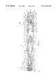
- FIG. 1 is an elevated view of an automatic injector having removal resistant cover constructed in accordance with the principles of the present invention
- FIG. 2 is a longitudinal sectional view in partial elevation along line 2 — 2 of FIG. 1 of the auto-injector assembled and constructed in accordance with the principles of the present invention
- FIG. 3 is a longitudinal sectional view of the auto-injector of the present invention and illustrating the actuation of the drive assembly and subsequent projection of the needle from the front end of the injector after manual depression of the actuator;
- FIG. 4 is a longitudinal sectional view of the auto-injector of the present invention and illustrating the dental cartridge having been moved onto the rear end of the hypodermic needle thereby puncturing the cartridge seal and establishing a flowpath for the fluid medicament;
- FIG. 5 is a longitudinal view of the auto-injector of the present invention and illustrating the dental cartridge plunger having been moved forward within the cartridge;
- FIG. 6 is a longitudinal sectional view of the auto-injector of the present invention and illustrating the deployment of the needle cover after the user completes the injection;
- FIG. 7A is a side plan view of the rearward portion of the auto-injector of the present invention and showing the cover being rotated into a position wherein the internal stops in the cap have reached the external stops on the injector body;
- FIG. 7B is a side plan view similar to FIG. 7A showing the removal resistant cover release portions having been squeezed and the subsequent alignment of the indicator arrows by further slight rotation of the cap over the stops;
- FIG. 7C is a side plan view similar to FIG. 7A showing the removal of the cover from the injector housing, thus exposing the actuator;
- FIG. 8 is an enlarged rear end plan view of the auto-injector device with the cover removed;
- FIG. 9 is an enlarged front end plan view of the cover showing the internal locking projections and external cap releasing portions
- FIG. 10 is an enlarged side plan view of the needle carrier showing the longitudinal, internal slots in dashed lines;
- FIG. 11 is an elevated view of an alternative embodiment of an auto injector constructed in accordance with the principles of the present invention.
- FIG. 12 shows an alternative cover.
- FIG. 1 shows an auto injector, generally indicated at 10 , constructed in accordance with principles of the present invention.
- the auto-injector 10 is generally comprised of a forward housing member 12 and a rearward housing member 14 connected together to define a housing with a longitudinal axis.
- a removal resistant cap 182 can be removed from the rear housing member to gain access to an actuating pin 136 that allows the user to initiate an automatic injection of an encapsulated medicament as will be described.
- the forward housing member 12 is an elongated, generally tubular, cylindrical plastic member that contains a dental cartridge assembly, generally indicated at 16 , and a needle assembly, generally indicated at 18 and including a protective needle cover assembly 20 .
- the rearward housing member 14 is an elongated, generally tubular cylindrical plastic member containing a manually operable drive assembly, generally indicated at 22 .
- the rearward housing member 14 is removably fixed to the forward housing member 12 by a snap-fit connection, as will be described herein.
- the dental cartridge assembly 16 includes a medicament container in the form of a dental cartridge 24 , which is tubular and made of glass.
- the dental cartridge 24 has forwardly and rearwardly facing openings at its opposite ends and is necked down at its forward end. More particularly, a major rearward portion 26 of the cartridge 24 extends rearwardly of a forward portion 28 and has an inner diameter which is larger than the inner diameter of the necked down forward portion 28 .
- the dental cartridge 24 has an inwardly extending annular shoulder 30 which integrally connects the main rearward portion 26 with the smaller diameter forward portion 28 .
- a forwardmost end 32 of the dental cartridge 24 has a radially extending annular flange 34 which receives a generally circular cartridge sealing member 36 , preferably made of an elastic or rubber material.
- the sealing member 36 is peripherally secured to an annular outer surface 38 of the flange 34 at the forward end 32 of the cartridge 24 by means of an annular metallic clamping ring 40 , thereby sealing off the forwardly facing opening at the forwardmost end 32 of the cartridge 24 .
- the clamping ring 40 has a centrally disposed aperture 42 to enable the sealing member 36 to be pierced by a rearward tip portion of a needle 58 of the needle assembly 18 upon actuation of the drive assembly 22 .
- the necked-down portion 28 of the cartridge 24 has a rubber washer 44 fixedly mounted thereto in surrounding relation.
- the washer 44 may be referred to as a third sealing member whose sealing function will be discussed below.
- a movable plunger 46 also preferably made of an elastic or rubber material, closes and internally seals the open rearward end 48 of the dental cartridge 24 and has a small, centrally disposed bore 50 in its rear face 52 .
- the bore 50 provides a means for directly connecting to the drive assembly 22 .
- the movable plunger 46 and sealing member 36 cooperate to seal a medicament 53 within the cartridge 24 .
- the plunger 46 has a forwardly extending nipple type configuration 54 constructed and arranged to fit within the smaller inner diameter of the forward end of the cartridge 24 so as to substantially expel all medicament from the cartridge 24 .
- the plunger 46 is slidably mounted within cartridge 24 for forward sliding movement in sealing relation with the interior surface of the cartridge 24 .
- the aforementioned arrangement for the nipple type plunger 46 and the dental cartridge 24 are disclosed in the U.S. patent application Ser. No. 08/280,884 (abandoned in favor of a continuation application, U.S. patent application Ser. No. 08/548,762, issued as U.S. Pat. No. 5,713,866), which is incorporated by reference into the present application. It can be appreciated, however, that this arrangement is merely preferred and that the present invention contemplates that any type of plunger now known or later developed can be used.
- the needle assembly 18 comprises a needle carrier 56 and a sterilized hypodermic needle 58 mounted to the carrier 56 .
- the needle carrier 56 has a substantially cup-shaped or tubular cartridge mounting portion 60 having a rearwardly facing cartridge receiving opening.
- the forward end 28 of the medicament cartridge 24 extends partially into the cartridge mounting portion 60 in telescopic relation.
- An annular groove 62 is formed externally at the rear of the cup-shaped portion 60 .
- the interior surface of cartridge mounting portion 60 towards the rear thereof has an annular detent groove 64 .
- a peripheral edge 66 of rubber washer 44 engages the detent groove 64 , preventing forward movement of the medicament cartridge 24 relative to the needle assembly 18 prior to or during the initial phase of injector activation.
- the internal surface of the cartridge mounting portion 60 of the needle assembly 18 has a series of circumferentially spaced, narrow, longitudinal slots or grooves 68 starting from the rearwardmost end of the mounting portion 60 and extending forwardly toward the rearwardly facing annular surface 67 , thus traversing the detent groove 64 . Because the groove 64 is of the same or greater depth relative to the depth of slots 68 , the annular elastic washer 44 forms an airtight seal with groove 64 .
- the slots 68 forwardly of groove 64 allow bleeding/venting of the air within space 69 of mounting portion 60 past the washer 44 in order to prevent any pressure build-up in space 69 which might hinder medicament injection or otherwise cause air to be forced into the cartridge 24 and out through the needle 58 .
- the slots 68 rearwardly of groove 64 also prevent pressure build-up in space 69 during assembly.
- the disclosed medicament cartridge is movable, it is to be understood that some aspects of the present invention may be practiced without the use of movable cartridge.
- the type of cartridge wherein the forward seal bulges out to be pierced by the needle as a result of pressure applied by the drive assembly may be used.
- the needle carrier 56 has a substantially narrowed diameter tubular forward portion 70 disposed in surrounding relation to the hypodermic needle 58 , thus forming a forwardly facing annular engaging surface 72 at the transition between mounting portion 60 and forward portion 70 .
- the flange surface 72 is chamfered along an outer peripheral sloped edge 74 to allow for smooth forward sliding motion within the forward housing member 12 .
- forward movement of needle assembly 18 causes edge 74 to eventually engage a rearwardly facing engaging surface 76 formed internally on the forward housing member 12 .
- a forwardmost portion 78 of tubular portion 70 has an “O” ring groove in which an O-ring 82 is placed in sealing relation to an interior surface 100 of the protective needle cover 20 .
- the O-ring 82 may be referred to as a second sealing member whose sealing function will be discussed below.
- the O-ring 82 may either seal the path hermectically or define a tortious path around it through which the air will not flow under normal conditions.
- the interior of the needle cover 90 has an annular groove 83 formed thereon.
- This groove 83 receives the O-ring 82 before the cover 90 and carrier 56 are assembled with the housing.
- the groove 83 and the O-ring 82 cooperate to keep the cover 90 locked in place.
- the cover 90 is pushed rearwardly so that the groove 83 disengages from the O-ring 82 with the O-ring being disposed in the location shown in FIG. 2 .
- the hypodermic needle 58 is a substantially narrow, elongated hollow tubular steel member with forward and rearward tip portions.
- the needle 58 has a lateral slot 84 on one side thereof at the rearward tip portion 86 to allow unimpeded flow of fluid through the needle, even in the event of an obstruction at the rearward opening at rearward end 86 of the needle 58 .
- the forward tip portion also has an opening to allow the medicament to flow into the injection site. The openings in the forward tip portion and the rearward tip portion are communicated by a fluid passageway.
- the type of needle shown is known as an ‘anti-coring needle’, an example of which is disclosed in U.S. Pat. No. 5,716,348.
- the location of the openings on the needle are not critical and may be located at the very tip of each end or spaced inwardly therefrom along the tip portions.
- the rearward tip portion 86 of the needle 58 is configured to puncture the medicament cartridge sealing member 36 to establish fluid communication with medicament 53 .
- the needle 58 is secured at a central exterior portion thereof to needle carrier 56 of the hub assembly 18 by means of an adhesive 88 or any other suitable means.
- the protective needle cover assembly As shown in FIG. 2, the protective needle cover assembly, indicated at 20 comprises a rigid plastic protective cover 90 and a forwardly disposed rubber seal 92 at the forward end of cover 90 providing a sterile barrier for the needle 58 , a cover locking assembly 91 , and a cover extension spring 94 .
- the seal 92 may be referred to as a first sealing member whose sealing function will be discussed below.
- the protective cover 90 is substantially tubular, and has a rearward portion 96 of a slightly smaller outer diameter so as to form a rearwardly facing annular shoulder 98 .
- the spring 94 has its forward volute resting on the rearwardly facing annular shoulder 98 and its rearward volute resting on the forwardly facing annular engaging surface 72 formed on the needle carrier 56 with the spring 94 slightly stressed therebetween.
- the inner surface 100 of the needle cover 90 tapers outwardly as it extends forwardly, thus enabling disengagement of O-ring 82 with surface 100 during activation and providing for unimpeded movement of the needle carrier 56 and needle 58 through needle cover 90 .
- the protective cover 90 is biased by the extension spring 94 to move forwardly in surrounding protective relation over the needle 58 after actuation of the injection device 10 as will be described.
- the inner surface of the forward end of the protective needle cover 90 has an inwardly facing annular groove 102 forming an annular shoulder 104 at the forwardmost end.
- the rubber seal 92 is securely fixed into groove 102 an outwardly extending peripheral edge 106 of the seal 92 received in groove 104 .
- a radially projecting annular ridge 108 is formed on the exterior of the protective cover 90 and has a rearwardly and outwardly sloping surface 110 .
- Mid-positioned on the protective cover 90 is a radially inwardly and forwardly tapering surface portion 111 forwardly terminating in an annular groove, and a rearwardly facing annular shoulder 112 .
- Formed on the interior surface 100 of the protective cover 90 is an inwardly extending 114 protrusion that acts as a backstop for O-ring 82 .
- the forward tip portion of needle 58 and the forward portion 70 of the needle carrier 56 are telescopically received into the carrier receiving opening of the needle cover 90 , with the spring 94 mounted between the needle carrier 56 and cover assembly 20 .
- the O-ring 82 is pushed over the protrusion 114 and, once in position, the cover 90 and needle carrier 56 cannot be easily pulled apart. With the spring 94 slightly tensioned, the O-ring 82 backseats against the protrusion 114 and, acting in cooperation with the protective cover forward seal 92 , seals the forward tip portion of the needle 58 within the cover 90 .
- the entire needle 58 is sealed airtight after assembly.
- the medicament 53 can be sterilized, e.g., by steam autoclaving after assembly, without exposing the needle 58 to moisture or other elements during sterilization.
- these components are sterilized before assembly and then assembled in a sterile area.
- the sealing maintains the sterility of the needle 56 by preventing contaminated (i.e., non-sterile) air from entering the needle assembly 18 and thereby contaminating the needle 58 .
- first sealing member seal 92
- second sealing member O-ring 82
- third sealing member washer 44
- first sealing member seal 92
- second sealing member O-ring 82
- third sealing member washer 44
- the type, configuration, or positioning of the sealing members can be changed or modified as long as such substantial sealing is provided.
- the sealing may be hermetic or via tortious paths formed around the seals.
- the needle carrier 56 is mounted to the needle cover 90 and the cartridge 24 is mounted to the needle carrier 56 in a sterilized area, such as a sterile room.
- the needle 58 may be pre-mounted to the needle carrier 56 or may also be mounted to the needle carrier in a sterile area. After assembly these components define a needle and guide cartridge assembly which may be carried or shipped to an unsterile assembly area where the drive assembly 22 and the needle and guide assembly can be mounted within the housing.
- the use of the needle cover 90 is particularly useful in this assembly method because the cover 90 provides rigid protection for the needle 58 .
- releasable spring drive assembly 22 is provided within the rearward housing portion 14 of the injector device 10 .
- the drive assembly 22 includes a coil drive spring 116 and a molded plastic collet member, generally indicated at 118 .
- the rearward housing member 14 is formed with an interior annular flange 120 spaced forward of the rearwardmost end thereof.
- the forward surface 122 of the annular flange 120 is adapted to be engaged by a rearward volute of the drive spring 116 , which operates as a releasable energy source for the injector 10 of the present invention.
- the forward volute of the drive spring 116 engages a rearwardly facing surface 124 of a mid-positioned flange 125 of the collet member 118 .
- the collet member 118 further includes a longitudinal, cylindrical shaft portion 126 that extends rearwardly from the mid-positioned flange 125 within the interior of drive spring 116 .
- a rearward end portion of the cylindrical shaft portion 126 is split so as to form a plurality (two) of rearwardly extending, resilient collet arms 128 separated by a space 127 .
- the rearward peripheral portion of the arms 128 are formed with radially outwardly extending flanges 130 presenting forwardly facing locking surfaces 132 which are adapted to engage along annular surface 134 of the interior annular flange 120 of the rear housing member 14 .
- An actuator in the form of an actuating pin member 136 is disposed between the resilient arms 128 , locking them apart in a storage or inoperative position. More specifically, pin 136 comprises a forward portion 138 that extends into the slot 127 between the resilient arms 128 , preventing arms 128 from moving towards one another in FIG. 2 .
- the actuating pin member 136 also has an intermediate portion 140 of a reduced diameter with respect to the forward portion 138 , there being a frustoconical transition between the two portions.
- a rigid, generally cylindrical head 141 is formed at the back end of the intermediate portion 140 .
- the head 141 has a generally cylindrical side wall surface 200 with an exterior diameter slightly smaller than the interior surface 202 of the rearward end portion of the rearward housing portion 14 .
- the interior surface 202 of the rearward end portion defines an actuator head receiving opening and a portion of the actuator head 141 is received therein such that the exterior side wall surface 200 thereof faces the interior surface 202 in closely spaced relation.
- This closely spaced relation substantially prevents radial bending of the pin member 136 and provides a more robust actuator.
- damage to the pin member 136 can be prevented to ensure proper actuation of the drive assembly 22 .
- the head 141 is solid and has two grooves 204 extending laterally thereacross. It is to be understood that the head 141 have other configurations other than cylindrical. For example, it is contemplated that the head 141 could have a square cross-section.
- the larger forward portion 138 of pin member 136 is cylindrically formed and, in the assembled position shown, engages the rearward, generally arcuate inner facing surfaces 139 of the resilient arms 128 so as to prevent the arms 128 from moving radially inwardly toward one another, thereby maintaining the locking surfaces 132 of the arms 128 in engagement with the rearward facing locking surface 134 of interior flange 120 .
- the drive spring 116 is retained in stressed position between the mid-positioned flange face 124 of the collet member 118 and the forwardly facing surface 122 of the interior flange 120 of the rearward housing member 14 .
- Radially inwardly extending ridges 142 extend along the inner arcuate surfaces of the collet arms 128 .
- the ridges 142 act as a stop, or detent force, against any applied forward motion of the actuating pin 136 so as to prevent the accidental actuation of the injector device 10 until a sufficient amount of force is applied to clear the ridges 142 .
- the forward portion 138 first rides over ridges 142 , it tends to bias the arms 128 outwardly away from one another. After the majority of forward portion 138 is beyond ridges 142 , the arms are forced to collapse inwardly under the force of spring 116 to release surfaces 132 from surface 134 , enabling collet 118 to be thrust forward.
- An annular groove 143 is formed around the forward portion 138 .
- the groove 143 receives the ridges 142 during forward movement of the pin member 136 . This arrangement allows the collapsing of the collet arms to occur sooner and with less force being applied to the pin member 136 in comparison to pin members without such a groove.
- a concentric series of elongated guide ribs 144 extend forwardly from the mid-positioned flange 125 to a tapered forward flange 146 and are received into the open rearward end 48 of the medicament cartridge 24 .
- a short, blunt-nosed, substantially arrow shaped portion 148 of reduced diameter extends forwardly from the tapered flange 146 and is received into the centrally located bore 50 at the rear of the plunger 46 , thus directly connecting the spring drive assembly 22 to the medicament cartridge plunger 46 .
- the forward end of the rearward housing member 14 is telescopically received into the rearward end of the forward housing member 12 . More particularly, the forward end of the rearward housing member 14 has an annular flange 150 radially extending outwardly from an exterior surface 152 thereof. The exterior surface 152 is of a narrower outer diameter than that of the main body of the rearward housing member 14 so as to permit the telescopic reception.
- the forward housing member 12 has an annular groove 156 formed on the interior surface 158 toward the rearward portion thereof.
- the forward housing member 12 is secured to the rear housing member 14 by rearwardly sliding the rearward end of the forward housing member 12 in telescoping relation over the forward end of the rear housing member 14 until the annular flange 150 of the rear housing member 14 snaps into the annular groove 156 of the forward housing member 12 .
- a rearward end portion 160 of the rearward housing member 14 has an outer diameter that is smaller than the main central portion 154 and sized to receive the removal resistant cover 182 .
- the rearward end portion 160 has a forward portion 190 and a rearward portion 192 , with the rearward portion 192 having a large outer diameter than forward portion 190 .
- a pair of generally axially extending grooves 188 are formed through rearward portion 192 and form a continuous surface with forward portion 190 .
- a generally radially extending shoulder surface 193 is defined between the forward and rearward portions 190 , 192 .
- the forward end of the plastic forward housing member 12 has two integrally formed opposing resilient finger snaps 168 biased radially inward into the housing member 12 through associated openings 170 of the forward housing member 12 .
- the snaps 168 provide forwardly facing locking surfaces 172 .
- the finger snaps 168 are disposed adjacent to and forwardly of the forwardly and radially inwardly tapered surface 111 on the exterior surface of the needle cover 90 , and rearwardly of the rearwardly facing needle cover annular shoulder 112 .
- the tapered surface 111 rides past linger snaps 168 , forcing finger snaps 168 outwards.
- annular ridge 108 slides past the finger snap locking surfaces 172 .
- Forward movement of the needle cover 90 is stopped when the sloping surface 110 of ridge 108 rides past finger snaps 168 and contacts the rear facing edges 180 formed at openings 170 as shown.
- the snap fingers 168 are disposed such that forwardly facing locking surfaces 172 thereof are behind the needle cover rearwardly facing shoulder 98 .
- the finger snaps 168 and the shoulder 98 cooperate to secure the needle cover 90 in an extended, needle covering protective position (see FIG. 6) after an injection operation and preventing anyone from pushing the needle cover 90 back into the forward housing member 12 and exposing the needle 58 .
- the rearward end portion 160 of the injection device 10 has a generally tubular, molded plastic cover 182 disposed in releasably locked covering relation with respect to actuating pin 136 .
- the cover 182 has an annular side wall portion and a top wall portion formed integrally with the side wall portion.
- FIG. 9 which is a front end plan view of cover 182
- the forwardmost end of the cover 182 has two integrally formed, diametrically opposed, outwardly protruding cap release portions 184 on the outer surface.
- the forwardmost end of cover 182 also has two diametrically opposed, radially inwardly protruding locking projections 186 on the inner surface thereof.
- the locking projections 186 extend rearwardly from the forwardmost end of the inner surface of the cover 182 to an intermediate portion on the inner surface of the cover 182 , as can be appreciated from FIGS. 7A-7C.
- the inwardly protruding locking projections 186 and the outwardly protruding cap release portions 184 are offset approximately 90 degrees from one another on the forwardmost portion of the cover 182 .
- Alignment indicators 187 are embossed on the outer surface of the cover 182 at positions on the cap corresponding to the positions at which the internal locking projections 186 are disposed.
- Other alignment indicators 189 are embossed on the rear housing portion 14 at positions longitudinally aligned with the pair of axially extending grooves 188 in the enlarged diameter portion 192 .
- the alignment indicators 187 , 189 are in the form of arrows as shown, but may be dots or any other recessed, embossed, or labeled indication marking.
- the rearward end portion 160 is comprised of a forward portion 190 and a rearward portion 192 with a generally radially extending shoulder surface 193 extending therebetween.
- the difference in diameter is substantially equal to the height of the locking projections 186 on cap 182 .
- two diametrically disposed movement limiting projections 194 are disposed on the forward portion 190 .
- Projections 194 are forwardly disposed from and in general, circumferential alignment with grooves 188 as shown.
- the projections 194 are also generally circumferentially aligned with indicators 189 and protrude from the rearward end portion 160 generally to the same extent as the locking projections 186 extend inwardly from the inner surface of the cover 182 .
- the movement limiting projections 194 and the projections 186 abut one another to prevent the alignment indicators 187 and 189 from being aligned with one another upon simple turning of the cover 182 .
- locking projections 186 cannot be aligned with grooves 188 on the injector body and the cover 182 cannot be removed from covering relation with respect to actuating pin member 136 .
- This position may be considered to be a removal resisting position.
- the indicators 187 and 189 In order to remove the cover 182 , the indicators 187 and 189 must be aligned, so that the locking projections 186 of cover 182 can be generally circumferentially aligned with grooves 188 and pulled axially rearwardly therethrough. The cover 182 may be considered to be in a removal allowing position when the locking projections 186 are aligned with the grooves 188 . In order to align indicators 187 and 189 , the cap release portions 184 must be manually squeezed.
- the plastic material forming cover 182 is sufficiently yieldingly deformable such that squeezing the portions 184 will distort the cross sectional shape of the cap 182 into a generally oval configuration, thus moving locking projections 186 generally radially outwardly away from one another from a normal, locking position to a releasing position.
- the cover 182 can be rotated so that projections 186 are disposed in overlapping alignment with movement limiting projections 194 , as can be appreciated from FIG. 7 B.
- the indicators 187 and 189 are now aligned, and the cover 182 can be pulled off the injection body, with locking projections 186 passing through grooves 188 .
- the locking projections 186 , the grooves 188 , the movement limiting projections 194 , and the shoulder surface 193 may be reversed so that the structure defining the groove 188 and the shoulder surface 193 is located on the interior of the cap 182 and the locking projections 186 are located on the housing 12 .
- the construction shown in the Figures is preferred because it is easier to manufacture.
- the user grasps the body of the injector device 10 and places the forwardmost end portion 176 against the portion of flesh to be injected.
- the actuating pin member 136 is then urged forwardly by a thumb or finger with enough force to overcome the engagement of the forward portion 138 with the ridges 142 .
- the intermediate narrower portion 140 of actuating pin 136 then moves into the slotted area 127 , closer to locking surface 132 and 134 .
- the rearward end of the collet arms 128 are thus permitted to deflect inwardly towards the narrower portion 140 to an extent sufficient that the locking surfaces 132 slidingly disengage from the interior annular flange locking surfaces 134 under the force of spring 116 .
- the collet member 118 then moves forwardly by the action of the drive spring 116 , initially pulling the pin 136 forward within slot 127 .
- the actuating pin member 136 is left behind in captured relation within the cup-shaped end 164 of rear housing member 14 thereby preventing the actuating pin 136 from becoming a loose part.
- the collet member 118 is driven forwardly against the rear end 52 of the slidable plunger 46 .
- This urges both the medicament cartridge 24 and needle carrier 56 forwardly until the peripheral sloped edge 74 of needle carrier 56 engages the engaging surface 76 on the interior surface of forward housing 12 , preventing any further forward movement of the needle carrier 56 .
- the needle 58 is in the injecting position.
- the plunger 46 does not move relative to cartridge 24 due to incompressibility of medicament 53 .
- cartridge 24 does not move relative to needle carrier 56 as a result of the interengagement between the washer 44 and the groove 64 .
- the forward movement of the needle carrier 56 compresses the extension spring 94 against the rearwardly facing shoulder 98 of the needle cover 90 . Also, the movement of the needle assembly 18 causes the front end of the needle 58 to puncture the rubber seal 92 at the forwardmost end 176 of the injector device 10 and be pushed into the injection site.
- fluid medicament 53 begins to flow through the needle. More specifically, the drive spring 116 pushes the plunger 46 forwardly within medicament cartridge 24 , thereby forcing the fluid medicament 53 outwardly from the cartridge 24 and through the needle 58 into the injection site. The plunger 46 slidingly moves to the forwardmost position within the medicament cartridge 24 to substantially expel all of the fluid medicament 53 therein. It can be appreciated, however, that the distance between the front end of the collet 188 and the flange may have a shorter length such that the plunger does not move all the way forward inside the cartridge 24 .
- This arrangement is preferred when it is desired to expel only a portion of the medicament 53 from the cartridge 24 .
- Epinephrine it is desirable to have a cartridge with a 1 ml supply and the collet is configured to cause only 0.3 ml to be injected into the injection site.
- expensive medicaments however, it is more cost-effective to expel as much medicament as possible to avoid waste.
- the needle cover 90 is moved forwardly by the extension spring 94 into the protective position. More specifically, the needle cover extension spring 94 is compressed upon actuation of the injector device 10 . The return spring 94 biases the needle cover 90 for forward movement, overcoming the finger snaps 168 retaining it within forward housing 12 . However, while the user holds the injector device 10 against the injection site, the needle cover 90 remains in place. Once the injection device 10 is removed from the injection site, the extension spring 94 drives the needle cover 90 forwardly.
- the needle cover ridge 108 then slides past finger snaps 168 , whereupon the locking surfaces 172 snap inwardly behind shoulder 98 so as to secure the needle cover 90 in the forwardly extending protective position.
- the needle cover 90 now projects forwardly beyond the forwardmost end 176 of the injector device 10 , covering the forward portion of the needle 58 for disposal of the device.
- FIG. 11 shows an alternative embodiment of an auto-injector constructed in accordance with the principles of the present invention, generally indicated at 10 ′.
- the auto injector 10 ′ is identical to the one shown in FIGS. 1-10, with certain exceptions.
- identical reference numerals marked in FIG. 11 as prime will correspond to the same features in the auto-injector of FIGS. 1-10.
- the main difference in this embodiment is that the movement limiting projections 194 have been removed so that deforming the cap 182 ′ is not necessary for removal.
- This arrangement is preferable for injectors which are to be used by children or other people with low manual dexterity, such as arthritis sufferers.
- FIG. 12 shows an alternative cover 182 ′′ that may be utilized in pace of covers 182 and 182 ′.
- the cover 182 ′′ has release portions 184 ′′ similar to the other covers dislclosed and includes an internal annular ridge 210 .
- the housing rear end will have four arcuate ridge portions (not shown) spaced annularly about its exterior and an annular groove (not shown) is formed forwardly of the acrucate ridge portions.
- the cover is positioned on the rear end portion with the ridge 210 engaged in the groove.
- To cover 182 ′′ is removed by pulling axially rearwardly with sufficient force to cause the ridge 210 to ride up and over the arcuate ridge portions.
- the engagement between the groove and the ridge 210 is basically a detent relationship.
- the auto-injector device 10 incorporates a needle cover assembly 20 that replaces the traditional needle sheath and provides rigid protection for the needle 58 .
- the rigid needle cover 90 encapsulates the forward end of the needle after an injection and prevents the user from seeing the needle 58 as it is withdrawn from the injection site.
- the needle cover 90 also locks in the extended protective position thereby preventing undesirable access to the needle 58 after an injection operation.
- the activation pin 136 snap-fit interference with the resilient collet arms 128 provides for a controlled activation load which must be applied in order to actuate the auto-injection device 10 .
- the needle 58 is sealed within the device 10 prior to use, to allow for post-assembly sterilization of medicament by means of autoclaving with a pressurized steam/air mixture. More specifically, the rubber washer 44 , O-ring 82 , and needle cover forward seal 92 isolate the needle 58 preventing moisture ingress into the needle area during sterilization. A secondary function of the rubber washer 44 is to provide a detent snap to keep the medicament cartridge 24 back prior to activation of the device, and to prevent the rear end 86 of the needle 58 separated from the forward cartridge seal 36 prior to activation of the device.
Abstract
Description
Claims (39)
Priority Applications (1)
| Application Number | Priority Date | Filing Date | Title |
|---|---|---|---|
| US09/212,570 US6210369B1 (en) | 1997-12-16 | 1998-12-16 | Automatic injector |
Applications Claiming Priority (2)
| Application Number | Priority Date | Filing Date | Title |
|---|---|---|---|
| US6977597P | 1997-12-16 | 1997-12-16 | |
| US09/212,570 US6210369B1 (en) | 1997-12-16 | 1998-12-16 | Automatic injector |
Publications (1)
| Publication Number | Publication Date |
|---|---|
| US6210369B1 true US6210369B1 (en) | 2001-04-03 |
Family
ID=22091145
Family Applications (1)
| Application Number | Title | Priority Date | Filing Date |
|---|---|---|---|
| US09/212,570 Expired - Fee Related US6210369B1 (en) | 1997-12-16 | 1998-12-16 | Automatic injector |
Country Status (9)
| Country | Link |
|---|---|
| US (1) | US6210369B1 (en) |
| EP (1) | EP1039942B1 (en) |
| JP (1) | JP2002508225A (en) |
| AU (1) | AU738058B2 (en) |
| CA (1) | CA2315146C (en) |
| DE (1) | DE69827036T2 (en) |
| IL (2) | IL136714A0 (en) |
| WO (1) | WO1999030759A2 (en) |
| ZA (1) | ZA9811594B (en) |
Cited By (212)
| Publication number | Priority date | Publication date | Assignee | Title |
|---|---|---|---|---|
| US20010011171A1 (en) * | 1999-10-14 | 2001-08-02 | Alchas Paul G. | Intradermal delivery device including a needle assembly |
| WO2002047746A1 (en) * | 2000-12-14 | 2002-06-20 | Shl Medical Ab | Auto-injector |
| WO2002083215A1 (en) * | 2001-04-13 | 2002-10-24 | Becton Dickinson And Company | Intradermal needle |
| WO2002083213A1 (en) * | 2001-04-13 | 2002-10-24 | Becton Dickinson And Company | Prefillable intradermal delivery device |
| US6478771B1 (en) * | 1998-11-13 | 2002-11-12 | Elan Pharma International Limited | Drug delivery systems and methods |
| US20020198509A1 (en) * | 1999-10-14 | 2002-12-26 | Mikszta John A. | Intradermal delivery of vaccines and gene therapeutic agents via microcannula |
| US20030049833A1 (en) * | 1998-06-24 | 2003-03-13 | Shuqi Chen | Sample vessels |
| WO2003039632A2 (en) * | 2001-11-02 | 2003-05-15 | Meridian Medical Technologies, Inc. | A medicament container, a medicament dispensing kit for administering medication and a method for packaging the same |
| US6569123B2 (en) | 1999-10-14 | 2003-05-27 | Becton, Dickinson And Company | Prefillable intradermal injector |
| US6569143B2 (en) | 1999-10-14 | 2003-05-27 | Becton, Dickinson And Company | Method of intradermally injecting substances |
| US20030100862A1 (en) * | 2001-07-19 | 2003-05-29 | Edwards Evan T. | Medical injector |
| US6575939B1 (en) * | 1998-02-04 | 2003-06-10 | Sanofi-Synthelabo | Device for automatic injection of a dose of medicinal product |
| US6607508B2 (en) | 2000-04-27 | 2003-08-19 | Invivotech, Inc. | Vial injector device |
| US20030199822A1 (en) * | 1999-10-14 | 2003-10-23 | Alchas Paul G. | Intradermal needle |
| US6689118B2 (en) | 1999-10-14 | 2004-02-10 | Becton Dickinson And Company | Method of intradermally injecting substances |
| US20040030293A1 (en) * | 2001-02-12 | 2004-02-12 | Thomas Gurtner | Reading aid for a device for administering a settable dosage of an injectable product |
| US20040092875A1 (en) * | 2002-11-08 | 2004-05-13 | Kochamba Gary Steven | Cutaneous injection delivery under suction |
| US6748332B2 (en) * | 1998-06-24 | 2004-06-08 | Chen & Chen, Llc | Fluid sample testing system |
| US20040133159A1 (en) * | 2003-01-07 | 2004-07-08 | Haider M. Ishaq | Disposable injection device |
| US6776776B2 (en) | 1999-10-14 | 2004-08-17 | Becton, Dickinson And Company | Prefillable intradermal delivery device |
| US6808511B2 (en) * | 2001-10-11 | 2004-10-26 | Gary J. Pond | Disposable aspirating safety syringe |
| US6808514B2 (en) | 2000-10-17 | 2004-10-26 | Patricia G. Schneider | Emergency medical dispensing card |
| US6843781B2 (en) | 1999-10-14 | 2005-01-18 | Becton, Dickinson And Company | Intradermal needle |
| US20050027255A1 (en) * | 2003-07-31 | 2005-02-03 | Sid Technologies, Llc | Automatic injector |
| US20050148933A1 (en) * | 2003-11-04 | 2005-07-07 | Raven Sophie R. | Container for medicament automatic injector and automatic injector adapted therefor |
| US20050171477A1 (en) * | 2002-05-23 | 2005-08-04 | Seedlings Life Science Ventures | Apparatus and method for rapid auto-injection of medication |
| US20050222539A1 (en) * | 2004-03-30 | 2005-10-06 | Pediamed Pharmaceuticals, Inc. | Automatic injection device |
| US20050273054A1 (en) * | 2004-06-03 | 2005-12-08 | Florida Atlantic University | Epinephrine auto-injector |
| US20060018877A1 (en) * | 2001-06-29 | 2006-01-26 | Mikszta John A | Intradermal delivery of vacccines and therapeutic agents |
| US20060178629A1 (en) * | 2004-12-09 | 2006-08-10 | Pharma-Pen Holdings, Inc. | Coupling for an auto-injection device |
| US20060178634A1 (en) * | 2004-12-06 | 2006-08-10 | Wyrick Ronald S | Medicine injection devices and methods |
| US20060264926A1 (en) * | 2002-11-08 | 2006-11-23 | Kochamba Gary S | Cutaneous stabilization by vacuum for delivery of micro-needle array |
| US20070017533A1 (en) * | 2004-12-06 | 2007-01-25 | Washington Biotech Corporation | Method and apparatus for delivering epinephrine |
| US20070088268A1 (en) * | 2004-11-22 | 2007-04-19 | Edwards Eric S | Devices systems and methods for medicament delivery |
| US20070149925A1 (en) * | 2004-11-22 | 2007-06-28 | Edwards Evan T | Devices, systems, and methods for medicament delivery |
| US20070167874A1 (en) * | 2002-04-19 | 2007-07-19 | Dominique Freeman | Method and apparatus for penetrating tissue |
| US20070173770A1 (en) * | 2006-01-23 | 2007-07-26 | The Medical House Plc | Injection device |
| US20080039789A1 (en) * | 2004-12-06 | 2008-02-14 | Wyrick Ronald E | Medicine injection devices and methods |
| US20080059133A1 (en) * | 2005-02-01 | 2008-03-06 | Edwards Eric S | Medical injector simulation device |
| US20080058719A1 (en) * | 2004-11-22 | 2008-03-06 | Edwards Evan T | Devices, systems and methods for medicament delivery |
| US20080103490A1 (en) * | 2005-02-01 | 2008-05-01 | Eric Shawn Edwards | Devices, systems and methods for medicament delivery |
| US20080228143A1 (en) * | 2004-01-23 | 2008-09-18 | The Medical House Plc | Injection Device |
| US20080269689A1 (en) * | 2005-02-01 | 2008-10-30 | Edwards Eric S | Medicament delivery device having an electronic circuit system |
| US20090024112A1 (en) * | 2005-02-01 | 2009-01-22 | Edwards Eric S | Medical injector with compliance tracking and monitoring |
| US20090043265A1 (en) * | 2007-08-10 | 2009-02-12 | Schneider Robert M | Method and apparatus for auto injection of a therapeutic |
| US20090270804A1 (en) * | 2004-08-06 | 2009-10-29 | Meridian Medical Technologies, Inc. | Automatic injector with needle cover |
| US20090299278A1 (en) * | 2006-05-03 | 2009-12-03 | Lesch Jr Paul R | Injector with adjustable dosing |
| US7648483B2 (en) | 2004-11-22 | 2010-01-19 | Intelliject, Inc. | Devices, systems and methods for medicament delivery |
| US7648468B2 (en) * | 2002-04-19 | 2010-01-19 | Pelikon Technologies, Inc. | Method and apparatus for penetrating tissue |
| US20100130930A1 (en) * | 2007-03-07 | 2010-05-27 | The Medical House Plc | autoinjector |
| US7731686B2 (en) | 2005-02-01 | 2010-06-08 | Intelliject, Inc. | Devices, systems and methods for medicament delivery |
| US20100152655A1 (en) * | 2006-01-23 | 2010-06-17 | The Medical House Plc | Improved autoinjector supporting the syringe at the front |
| EP2201974A1 (en) * | 2008-12-23 | 2010-06-30 | Sanofi-Aventis Deutschland GmbH | Medication delivery device |
| US20100185178A1 (en) * | 2009-01-20 | 2010-07-22 | Robert Sharp | Injection device |
| US20100185148A1 (en) * | 2008-06-20 | 2010-07-22 | West Pharmaceutical Services, Inc. | Injector Apparatus |
| US20100211005A1 (en) * | 2005-02-01 | 2010-08-19 | Edwards Eric S | Apparatus and methods for self-administration of vaccines and other medicaments |
| US20100218621A1 (en) * | 2003-02-05 | 2010-09-02 | Iquum, Inc. | Sample processing methods |
| US7794432B2 (en) | 2004-08-06 | 2010-09-14 | Meridian Medical Technologies, Inc. | Automatic injector with kickback attenuation |
| CN101282751B (en) * | 2005-07-18 | 2011-01-12 | 韦斯特制药服务公司 | Auto-injection syringe having vent device |
| US7875047B2 (en) | 2002-04-19 | 2011-01-25 | Pelikan Technologies, Inc. | Method and apparatus for a multi-use body fluid sampling device with sterility barrier release |
| US20110034879A1 (en) * | 2008-06-20 | 2011-02-10 | West Pharmaceutical Services, Inc. | Automatic Injection Mechanism with Frontal Buttress |
| US7892183B2 (en) | 2002-04-19 | 2011-02-22 | Pelikan Technologies, Inc. | Method and apparatus for body fluid sampling and analyte sensing |
| US20110054454A1 (en) * | 2009-08-26 | 2011-03-03 | Tyco Healthcare Group Lp | Gas-Enhanced Surgical Instrument with Mechanism for Cylinder Puncture |
| US7901365B2 (en) | 2002-04-19 | 2011-03-08 | Pelikan Technologies, Inc. | Method and apparatus for penetrating tissue |
| US7909778B2 (en) | 2002-04-19 | 2011-03-22 | Pelikan Technologies, Inc. | Method and apparatus for penetrating tissue |
| US7909774B2 (en) | 2002-04-19 | 2011-03-22 | Pelikan Technologies, Inc. | Method and apparatus for penetrating tissue |
| US7909775B2 (en) | 2001-06-12 | 2011-03-22 | Pelikan Technologies, Inc. | Method and apparatus for lancet launching device integrated onto a blood-sampling cartridge |
| US7909777B2 (en) | 2002-04-19 | 2011-03-22 | Pelikan Technologies, Inc | Method and apparatus for penetrating tissue |
| US20110143968A1 (en) * | 1998-06-24 | 2011-06-16 | Iquum, Inc. | Sample vessels |
| US7976476B2 (en) | 2002-04-19 | 2011-07-12 | Pelikan Technologies, Inc. | Device and method for variable speed lancet |
| US7981056B2 (en) | 2002-04-19 | 2011-07-19 | Pelikan Technologies, Inc. | Methods and apparatus for lancet actuation |
| US7981055B2 (en) | 2001-06-12 | 2011-07-19 | Pelikan Technologies, Inc. | Tissue penetration device |
| US7985216B2 (en) | 2004-03-16 | 2011-07-26 | Dali Medical Devices Ltd. | Medicinal container engagement and automatic needle device |
| US7988675B2 (en) | 2005-12-08 | 2011-08-02 | West Pharmaceutical Services Of Delaware, Inc. | Automatic injection and retraction devices for use with pre-filled syringe cartridges |
| US7988645B2 (en) | 2001-06-12 | 2011-08-02 | Pelikan Technologies, Inc. | Self optimizing lancing device with adaptation means to temporal variations in cutaneous properties |
| US8007446B2 (en) | 2002-04-19 | 2011-08-30 | Pelikan Technologies, Inc. | Method and apparatus for penetrating tissue |
| US20110209410A1 (en) * | 2008-11-05 | 2011-09-01 | West Pharmaceutical Services, Inc. | Barrier Isolator Port Assembly |
| US20110226646A1 (en) * | 2004-12-06 | 2011-09-22 | Wyrick Ronald E | Kits Containing Medicine Injection Devices And Containers |
| US8052645B2 (en) | 2008-07-23 | 2011-11-08 | Avant Medical Corp. | System and method for an injection using a syringe needle |
| US8062231B2 (en) | 2002-04-19 | 2011-11-22 | Pelikan Technologies, Inc. | Method and apparatus for penetrating tissue |
| US8079960B2 (en) | 2002-04-19 | 2011-12-20 | Pelikan Technologies, Inc. | Methods and apparatus for lancet actuation |
| WO2012022810A2 (en) | 2010-08-19 | 2012-02-23 | Novo Nordisk A/S | Medical injection device |
| US8162887B2 (en) | 2004-06-23 | 2012-04-24 | Abbott Biotechnology Ltd. | Automatic injection devices |
| US8177749B2 (en) | 2008-05-20 | 2012-05-15 | Avant Medical Corp. | Cassette for a hidden injection needle |
| US20120123346A1 (en) * | 2009-06-02 | 2012-05-17 | Sanofi-Aventis Deutschland Gmbh | Medicated module with needle guard |
| US8197421B2 (en) | 2002-04-19 | 2012-06-12 | Pelikan Technologies, Inc. | Method and apparatus for penetrating tissue |
| US8206360B2 (en) | 2005-02-01 | 2012-06-26 | Intelliject, Inc. | Devices, systems and methods for medicament delivery |
| US8221334B2 (en) | 2002-04-19 | 2012-07-17 | Sanofi-Aventis Deutschland Gmbh | Method and apparatus for penetrating tissue |
| US8251921B2 (en) | 2003-06-06 | 2012-08-28 | Sanofi-Aventis Deutschland Gmbh | Method and apparatus for body fluid sampling and analyte sensing |
| US8262614B2 (en) | 2003-05-30 | 2012-09-11 | Pelikan Technologies, Inc. | Method and apparatus for fluid injection |
| US8267870B2 (en) | 2002-04-19 | 2012-09-18 | Sanofi-Aventis Deutschland Gmbh | Method and apparatus for body fluid sampling with hybrid actuation |
| US8267890B2 (en) | 2003-01-30 | 2012-09-18 | Becton, Dickinson And Company | Intradermal delivery device with contoured skin engaging surface geometry |
| US20120253289A1 (en) * | 2009-07-31 | 2012-10-04 | The Medical House Limited | Autoinjector |
| US8282576B2 (en) | 2003-09-29 | 2012-10-09 | Sanofi-Aventis Deutschland Gmbh | Method and apparatus for an improved sample capture device |
| US8296918B2 (en) | 2003-12-31 | 2012-10-30 | Sanofi-Aventis Deutschland Gmbh | Method of manufacturing a fluid sampling device with improved analyte detecting member configuration |
| US20120302964A1 (en) * | 2009-09-30 | 2012-11-29 | Sanofi-Aventis Deutschland Gmbh | Assembly of a Drug Delivery Device |
| US8333710B2 (en) | 2002-04-19 | 2012-12-18 | Sanofi-Aventis Deutschland Gmbh | Tissue penetration device |
| US20130018326A1 (en) * | 2010-04-01 | 2013-01-17 | Enable Injections, Llc | Medical fluid injection device and system |
| US8360992B2 (en) | 2002-04-19 | 2013-01-29 | Sanofi-Aventis Deutschland Gmbh | Method and apparatus for penetrating tissue |
| US8366682B2 (en) | 2009-03-04 | 2013-02-05 | Washington Biotech Corporation | Medicine injection apparatuses |
| CN102917742A (en) * | 2010-03-10 | 2013-02-06 | 卢森堡梅纳利尼国际运营股份有限公司 | Device for the automatic injection of two doses of a medicament |
| US8372016B2 (en) | 2002-04-19 | 2013-02-12 | Sanofi-Aventis Deutschland Gmbh | Method and apparatus for body fluid sampling and analyte sensing |
| US8376998B2 (en) | 2003-09-17 | 2013-02-19 | Elcam Medical Agricultural Cooperative Association Ltd. | Automatic injection device |
| US8382682B2 (en) | 2002-04-19 | 2013-02-26 | Sanofi-Aventis Deutschland Gmbh | Method and apparatus for penetrating tissue |
| WO2013038166A1 (en) * | 2011-09-12 | 2013-03-21 | Owen Mumford Limited | Injector assembly |
| WO2013037744A1 (en) | 2011-09-13 | 2013-03-21 | Sanofi-Aventis Deutschland Gmbh | Injection device |
| US8425460B2 (en) | 2005-09-01 | 2013-04-23 | Owen Mumford Limited | Needle shroud assembly |
| US8435190B2 (en) | 2002-04-19 | 2013-05-07 | Sanofi-Aventis Deutschland Gmbh | Method and apparatus for penetrating tissue |
| US8439872B2 (en) | 1998-03-30 | 2013-05-14 | Sanofi-Aventis Deutschland Gmbh | Apparatus and method for penetration with shaft having a sensor for sensing penetration depth |
| US20130211337A1 (en) * | 2010-10-25 | 2013-08-15 | Sanofi-Aventis Deutschladn Gmbh | Injection device having a two-part plunger rod |
| US20130211326A1 (en) * | 2010-04-23 | 2013-08-15 | Sanofi-Aventis Deutschland Gmbh | Coded Cartridge Holder System for a Fluid Delivery Device |
| US8556829B2 (en) | 2002-04-19 | 2013-10-15 | Sanofi-Aventis Deutschland Gmbh | Method and apparatus for penetrating tissue |
| US8574895B2 (en) | 2002-12-30 | 2013-11-05 | Sanofi-Aventis Deutschland Gmbh | Method and apparatus using optical techniques to measure analyte levels |
| US8627816B2 (en) | 2011-02-28 | 2014-01-14 | Intelliject, Inc. | Medicament delivery device for administration of opioid antagonists including formulations for naloxone |
| US20140014705A1 (en) * | 2008-02-13 | 2014-01-16 | Ethicon Endo-Surgery, Inc. | Surgical stapling instrument |
| US8636704B2 (en) | 2009-04-29 | 2014-01-28 | Abbvie Biotechnology Ltd | Automatic injection device |
| US8641644B2 (en) | 2000-11-21 | 2014-02-04 | Sanofi-Aventis Deutschland Gmbh | Blood testing apparatus having a rotatable cartridge with multiple lancing elements and testing means |
| US8652831B2 (en) | 2004-12-30 | 2014-02-18 | Sanofi-Aventis Deutschland Gmbh | Method and apparatus for analyte measurement test time |
| US8668656B2 (en) | 2003-12-31 | 2014-03-11 | Sanofi-Aventis Deutschland Gmbh | Method and apparatus for improving fluidic flow and sample capture |
| US8679061B2 (en) | 2006-06-30 | 2014-03-25 | Abbvie Biotechnology Ltd | Automatic injection device |
| US8702624B2 (en) | 2006-09-29 | 2014-04-22 | Sanofi-Aventis Deutschland Gmbh | Analyte measurement device with a single shot actuator |
| US8708968B2 (en) | 2011-01-24 | 2014-04-29 | Abbvie Biotechnology Ltd. | Removal of needle shields from syringes and automatic injection devices |
| US8721671B2 (en) | 2001-06-12 | 2014-05-13 | Sanofi-Aventis Deutschland Gmbh | Electric lancet actuator |
| US8734393B2 (en) | 2009-04-23 | 2014-05-27 | The Medical House Limited | Autoinjector |
| US8747357B2 (en) | 2006-12-18 | 2014-06-10 | The Medical House Limited | Autoinjector |
| US8758301B2 (en) | 2009-12-15 | 2014-06-24 | Abbvie Biotechnology Ltd | Firing button for automatic injection device |
| US8784335B2 (en) | 2002-04-19 | 2014-07-22 | Sanofi-Aventis Deutschland Gmbh | Body fluid sampling device with a capacitive sensor |
| US8828203B2 (en) | 2004-05-20 | 2014-09-09 | Sanofi-Aventis Deutschland Gmbh | Printable hydrogels for biosensors |
| WO2014174519A1 (en) * | 2013-04-23 | 2014-10-30 | Elcam Medical Agricultural Cooperative Association Ltd. | Automatic injection device for administration of high viscosity medication |
| KR20150003198A (en) * | 2012-04-05 | 2015-01-08 | 사노피-아벤티스 도이칠란트 게엠베하 | Pen-type injector |
| US8939943B2 (en) | 2011-01-26 | 2015-01-27 | Kaleo, Inc. | Medicament delivery device for administration of opioid antagonists including formulations for naloxone |
| US8945063B2 (en) | 2009-03-20 | 2015-02-03 | Antares Pharma, Inc. | Hazardous agent injection system |
| US20150038914A1 (en) * | 2011-04-05 | 2015-02-05 | Covidien Lp | Medical Cartridge Receiver Having Access Device |
| US8965476B2 (en) | 2010-04-16 | 2015-02-24 | Sanofi-Aventis Deutschland Gmbh | Tissue penetration device |
| US20150080807A1 (en) * | 2012-04-13 | 2015-03-19 | Becton, Dickinson And Company | Self-injection device with indicator for indicating proper connection of components |
| US20150100024A1 (en) * | 2013-10-03 | 2015-04-09 | Jeff Baker | Medicament delivery and training cartridge system and mechanisms of actuation |
| US20150141776A1 (en) * | 2012-04-11 | 2015-05-21 | Pharmasens Ag | Subcutaneous needle insertion mechanism |
| US9044553B2 (en) | 2009-03-13 | 2015-06-02 | Eli Lilly And Company | Apparatus for injecting a pharmaceutical with automatic syringe retraction following injection |
| US9084849B2 (en) | 2011-01-26 | 2015-07-21 | Kaleo, Inc. | Medicament delivery devices for administration of a medicament within a prefilled syringe |
| US20150238696A1 (en) * | 2013-10-18 | 2015-08-27 | David Mundschenk | Method of dispensing material using a needle-less tip device and needle-less tip device |
| US9144401B2 (en) | 2003-06-11 | 2015-09-29 | Sanofi-Aventis Deutschland Gmbh | Low pain penetrating member |
| WO2015150578A1 (en) | 2014-04-04 | 2015-10-08 | Novo Nordisk A/S | Autoinjector having needle shield triggering |
| US9180259B2 (en) | 2005-01-24 | 2015-11-10 | Antares Pharma, Inc. | Prefilled syringe jet injector |
| US9180244B2 (en) | 2010-04-21 | 2015-11-10 | Abbvie Biotechnology Ltd | Wearable automatic injection device for controlled delivery of therapeutic agents |
| US9220660B2 (en) | 2011-07-15 | 2015-12-29 | Antares Pharma, Inc. | Liquid-transfer adapter beveled spike |
| WO2015197866A1 (en) | 2014-06-27 | 2015-12-30 | Novo Nordisk A/S | Autoinjector having needle shield triggering |
| US9226699B2 (en) | 2002-04-19 | 2016-01-05 | Sanofi-Aventis Deutschland Gmbh | Body fluid sampling module with a continuous compression tissue interface surface |
| US9248267B2 (en) | 2002-04-19 | 2016-02-02 | Sanofi-Aventis Deustchland Gmbh | Tissue penetration device |
| US9265887B2 (en) | 2011-01-24 | 2016-02-23 | Abbvie Biotechnology Ltd. | Automatic injection devices having overmolded gripping surfaces |
| US9314194B2 (en) | 2002-04-19 | 2016-04-19 | Sanofi-Aventis Deutschland Gmbh | Tissue penetration device |
| US9333309B2 (en) | 2002-02-11 | 2016-05-10 | Antares Pharma, Inc. | Intradermal injector |
| US9351680B2 (en) | 2003-10-14 | 2016-05-31 | Sanofi-Aventis Deutschland Gmbh | Method and apparatus for a variable user interface |
| US9364611B2 (en) | 2012-05-07 | 2016-06-14 | Antares Pharma, Inc. | Needle assisted jet injection device having reduced trigger force |
| US9375169B2 (en) | 2009-01-30 | 2016-06-28 | Sanofi-Aventis Deutschland Gmbh | Cam drive for managing disposable penetrating member actions with a single motor and motor and control system |
| US9386944B2 (en) | 2008-04-11 | 2016-07-12 | Sanofi-Aventis Deutschland Gmbh | Method and apparatus for analyte detecting device |
| US9393367B2 (en) | 2013-03-12 | 2016-07-19 | Antares Pharma, Inc. | Prefilled syringes and kits thereof |
| US9427532B2 (en) | 2001-06-12 | 2016-08-30 | Sanofi-Aventis Deutschland Gmbh | Tissue penetration device |
| US9446195B2 (en) | 2011-07-15 | 2016-09-20 | Antares Pharma, Inc. | Injection device with cammed ram assembly |
| US9486583B2 (en) | 2012-03-06 | 2016-11-08 | Antares Pharma, Inc. | Prefilled syringe with breakaway force feature |
| US9517307B2 (en) | 2014-07-18 | 2016-12-13 | Kaleo, Inc. | Devices and methods for delivering opioid antagonists including formulations for naloxone |
| US9522235B2 (en) | 2012-05-22 | 2016-12-20 | Kaleo, Inc. | Devices and methods for delivering medicaments from a multi-chamber container |
| US9542826B2 (en) | 2012-12-27 | 2017-01-10 | Kaleo, Inc. | Devices, systems and methods for locating and interacting with medicament delivery systems |
| US9561333B2 (en) | 2008-08-05 | 2017-02-07 | Antares Pharma, Inc. | Multiple dosage injector |
| WO2017032590A1 (en) * | 2015-08-26 | 2017-03-02 | Carebay Europe Ltd | Medicament delivery device and assembly of electronic device and the medicament delivery device |
| US20170106146A1 (en) * | 2014-07-01 | 2017-04-20 | Amgen Inc. | Autoinjector with Low Energy Plunger Loading |
| US9662652B2 (en) | 2000-12-29 | 2017-05-30 | Chen & Chen, Llc | Sample processing device for pretreatment and thermal cycling |
| WO2017089259A1 (en) * | 2015-11-27 | 2017-06-01 | Sanofi-Aventis Deutschland Gmbh | An injection device |
| WO2017114934A1 (en) | 2015-12-30 | 2017-07-06 | Novo Nordisk A/S | Autoinjector having needle shield triggering |
| US9707354B2 (en) | 2013-03-11 | 2017-07-18 | Antares Pharma, Inc. | Multiple dosage injector with rack and pinion dosage system |
| US9744302B2 (en) | 2013-02-11 | 2017-08-29 | Antares Pharma, Inc. | Needle assisted jet injection device having reduced trigger force |
| US9764091B2 (en) | 2011-09-09 | 2017-09-19 | Merck Patent Gmbh | Auto-injector for epinephrine injection |
| US9775553B2 (en) | 2004-06-03 | 2017-10-03 | Sanofi-Aventis Deutschland Gmbh | Method and apparatus for a fluid sampling device |
| US9795747B2 (en) | 2010-06-02 | 2017-10-24 | Sanofi-Aventis Deutschland Gmbh | Methods and apparatus for lancet actuation |
| US9808582B2 (en) | 2006-05-03 | 2017-11-07 | Antares Pharma, Inc. | Two-stage reconstituting injector |
| US9820684B2 (en) | 2004-06-03 | 2017-11-21 | Sanofi-Aventis Deutschland Gmbh | Method and apparatus for a fluid sampling device |
| US20170348486A1 (en) * | 2014-12-29 | 2017-12-07 | Novo Nordisk A/S | Drug delivery device with a hydraulic trigger mechanism |
| US9867949B2 (en) | 2008-03-10 | 2018-01-16 | Antares Pharma, Inc. | Injector safety device |
| US20180099087A1 (en) * | 2015-04-24 | 2018-04-12 | Becton, Dickinson And Company | Button safety cap for catheter insertion device |
| US9950125B2 (en) | 2012-04-06 | 2018-04-24 | Antares Pharma, Inc. | Needle assisted jet injection administration of testosterone compositions |
| US9974904B2 (en) | 2008-05-20 | 2018-05-22 | Avant Medical Corp. | Autoinjector system |
| CN108495677A (en) * | 2015-11-27 | 2018-09-04 | 赛诺菲-安万特德国有限公司 | medicament injection apparatus |
| CN108601911A (en) * | 2015-11-27 | 2018-09-28 | 赛诺菲-安万特德国有限公司 | medicament injection apparatus |
| USD829890S1 (en) | 2012-04-20 | 2018-10-02 | Amgen Inc. | Injection device |
| US10092703B2 (en) | 2013-03-15 | 2018-10-09 | Amgen Inc. | Drug cassette, autoinjector, and autoinjector system |
| US10092706B2 (en) | 2011-04-20 | 2018-10-09 | Amgen Inc. | Autoinjector apparatus |
| CN109331296A (en) * | 2018-11-27 | 2019-02-15 | 甘肃成纪生物药业有限公司 | A kind of injection needle and automated injection device |
| US10258336B2 (en) | 2008-09-19 | 2019-04-16 | Ethicon Llc | Stapling system configured to produce different formed staple heights |
| US10300213B2 (en) * | 2014-02-06 | 2019-05-28 | Novo Nordisk A/S | Cartridge and needle assembly in combination |
| US10332623B2 (en) | 2017-01-17 | 2019-06-25 | Kaleo, Inc. | Medicament delivery devices with wireless connectivity and event detection |
| US10357619B1 (en) | 2018-02-08 | 2019-07-23 | Chalbourne Brasington | Auto-injection device |
| US20190275252A1 (en) * | 2017-08-30 | 2019-09-12 | Pirouette Medical LLC | Compact auto-injector |
| US10434258B2 (en) | 2011-12-08 | 2019-10-08 | Sanofi-Aventis Deutschland Gmbh | Syringe carrier |
| US10492990B2 (en) | 2013-03-15 | 2019-12-03 | Amgen Inc. | Drug cassette, autoinjector, and autoinjector system |
| US10543322B2 (en) | 2015-01-22 | 2020-01-28 | Novo Nordisk A/S | Injection needle assembly for an injection device and an injection device comprising such assembly |
| US10576206B2 (en) | 2015-06-30 | 2020-03-03 | Kaleo, Inc. | Auto-injectors for administration of a medicament within a prefilled syringe |
| US10688244B2 (en) | 2016-12-23 | 2020-06-23 | Kaleo, Inc. | Medicament delivery device and methods for delivering drugs to infants and children |
| US10695495B2 (en) | 2015-03-24 | 2020-06-30 | Kaleo, Inc. | Devices and methods for delivering a lyophilized medicament |
| US10695053B2 (en) | 2006-09-29 | 2020-06-30 | Ethicon Llc | Surgical end effectors with staple cartridges |
| CN111388854A (en) * | 2020-03-18 | 2020-07-10 | 青岛市市立医院 | Infectious skin disease medicine applicator |
| US10737028B2 (en) | 2004-11-22 | 2020-08-11 | Kaleo, Inc. | Devices, systems and methods for medicament delivery |
| USD898908S1 (en) | 2012-04-20 | 2020-10-13 | Amgen Inc. | Pharmaceutical product cassette for an injection device |
| US10806867B2 (en) | 2011-01-24 | 2020-10-20 | E3D Agricultural Cooperative Association Ltd. | Injector |
| US10918803B2 (en) | 2015-06-03 | 2021-02-16 | Sanofi-Aventis Deutschland Gmbh | Syringe carrier for an autoinjector and method of assembling |
| US11027068B2 (en) | 2015-06-03 | 2021-06-08 | Sanofi-Aventis Deutschland Gmbh | Syringe support and autoinjector |
| US11058825B2 (en) | 2015-11-27 | 2021-07-13 | Sanofi-Aventis Deutschland Gmbh | Cap for an injection device |
| US11103649B2 (en) | 2015-06-03 | 2021-08-31 | Sanofi-Aventis Deutschland Gmbh | Autoinjector and method of assembling |
| US11167087B2 (en) | 2019-08-09 | 2021-11-09 | Kaleo, Inc. | Devices and methods for delivery of substances within a prefilled syringe |
| US11590286B2 (en) | 2004-11-22 | 2023-02-28 | Kaleo, Inc. | Devices, systems and methods for medicament delivery |
| USD994111S1 (en) | 2008-05-12 | 2023-08-01 | Kaleo, Inc. | Medicament delivery device cover |
| US11850401B2 (en) | 2018-06-08 | 2023-12-26 | Antares Pharma, Inc. | Auto-insert injector |
| US11929160B2 (en) | 2018-07-16 | 2024-03-12 | Kaleo, Inc. | Medicament delivery devices with wireless connectivity and compliance detection |
| US11944306B2 (en) | 2008-09-19 | 2024-04-02 | Cilag Gmbh International | Surgical stapler including a replaceable staple cartridge |
Families Citing this family (21)
| Publication number | Priority date | Publication date | Assignee | Title |
|---|---|---|---|---|
| US20060129122A1 (en) * | 2004-12-06 | 2006-06-15 | Wyrick Ronald E | Method and apparatus for delivering epinephrine |
| DE102005017477A1 (en) * | 2005-02-18 | 2006-08-31 | Tecpharma Licensing Ag | Spring in or for an injection device |
| GB2424836B (en) * | 2005-04-06 | 2010-09-22 | Cilag Ag Int | Injection device (bayonet cap removal) |
| JP5277157B2 (en) * | 2006-03-29 | 2013-08-28 | インテリジェクト,インコーポレイテッド | Drug delivery device |
| JP4131001B2 (en) * | 2006-07-28 | 2008-08-13 | 大成化工株式会社 | Metering device |
| DE602006007156D1 (en) * | 2006-11-29 | 2009-07-16 | Deborah Huang | Disposable syringe with built-in cartridge |
| AU2007229353B2 (en) * | 2007-10-17 | 2009-11-19 | Deborah Huang | Disposable syringe with built-in carpule |
| EP2482893A1 (en) | 2009-09-30 | 2012-08-08 | Sanofi-Aventis Deutschland GmbH | Drug delivery device |
| WO2014006754A1 (en) * | 2012-07-06 | 2014-01-09 | テルモ株式会社 | Liquid administration apparatus |
| WO2014009382A1 (en) * | 2012-07-11 | 2014-01-16 | Novartis Ag | Injection device |
| WO2014046950A1 (en) | 2012-09-24 | 2014-03-27 | Enable Injections, Llc | Medication vial and injector assemblies and methods of use |
| EP3003458B1 (en) * | 2013-05-31 | 2019-12-04 | 3M Innovative Properties Company | Microneedle injection apparatus comprising a dual cover |
| EP3003457B8 (en) | 2013-05-31 | 2021-02-24 | Kindeva Drug Delivery L.P. | Microneedle injection and infusion apparatus |
| MX353241B (en) | 2013-05-31 | 2018-01-05 | 3M Innovative Properties Co | Microneedle injection apparatus comprising an inverted actuator. |
| WO2014204894A2 (en) | 2013-06-18 | 2014-12-24 | Enable Injections, Llc | Vial transfer and injection apparatus and method |
| JP6727138B2 (en) * | 2014-06-05 | 2020-07-22 | サノフイSanofi | Actuation mechanism for drug delivery device and drug delivery device |
| EP3260149A1 (en) * | 2016-06-23 | 2017-12-27 | TecPharma Licensing AG | A method for fixation of a cartridge in an injection device |
| GB2560524B (en) * | 2017-03-13 | 2019-07-31 | Univ Cape Town | An auto-injector |
| BR112019020705A2 (en) * | 2017-05-05 | 2020-05-12 | Regeneron Pharmaceuticals, Inc. | AUTOINJECTOR |
| GB2592059A (en) * | 2020-02-14 | 2021-08-18 | Consort Medical Ltd | Improved injection device |
| USD1007676S1 (en) | 2021-11-16 | 2023-12-12 | Regeneron Pharmaceuticals, Inc. | Wearable autoinjector |
Citations (16)
| Publication number | Priority date | Publication date | Assignee | Title |
|---|---|---|---|---|
| US2752060A (en) | 1955-02-16 | 1956-06-26 | Warren N Martin | Container closure |
| US2827193A (en) | 1955-09-06 | 1958-03-18 | Warren N Martin | Closure cap for containers |
| US3166069A (en) | 1954-10-27 | 1965-01-19 | Astra Ab | Operating mechanism for automatic hypodermic syringes |
| US3399796A (en) | 1966-04-18 | 1968-09-03 | Steiner Maurice | Safety stopper for pharmaceutical bottles and flasks |
| US4105132A (en) | 1976-08-19 | 1978-08-08 | Keeler Frederick D | Tamper-proof closure |
| US4378015A (en) | 1981-12-21 | 1983-03-29 | Wardlaw Stephen C | Automatic injecting syringe |
| US4484910A (en) | 1983-12-21 | 1984-11-27 | Survival Technology, Inc. | Dual mode automatic injector |
| US4620640A (en) | 1985-12-16 | 1986-11-04 | Owens-Illinois, Inc. | Lined child-resistant closure for widemouth liquid container |
| US5085641A (en) | 1989-07-17 | 1992-02-04 | Survival Technology, Inc. | Conveniently carried frequent use auto-injector with improved cap structure |
| US5092843A (en) | 1990-04-12 | 1992-03-03 | Survival Technology, Inc. | Dispersion multichamber auto-injector |
| US5102393A (en) | 1989-07-17 | 1992-04-07 | Survival Technology, Inc. | Autoinjector converted from intramuscular to subcutaneous mode of injection |
| US5320609A (en) | 1992-12-07 | 1994-06-14 | Habley Medical Technology Corporation | Automatic pharmaceutical dispensing syringe |
| US5358489A (en) | 1993-05-27 | 1994-10-25 | Washington Biotech Corporation | Reloadable automatic or manual emergency injection system |
| WO1995021645A1 (en) | 1994-02-14 | 1995-08-17 | Genentech, Inc. | Self administered injection pen apparatus and method |
| US5540664A (en) | 1993-05-27 | 1996-07-30 | Washington Biotech Corporation | Reloadable automatic or manual emergency injection system |
| US5569192A (en) | 1992-03-27 | 1996-10-29 | Duphar International Research B.V. | Automatic injector |
Family Cites Families (5)
| Publication number | Priority date | Publication date | Assignee | Title |
|---|---|---|---|---|
| US3783997A (en) * | 1972-04-17 | 1974-01-08 | Sherwood Medical Ind Inc | Syringe package |
| IL114767A (en) | 1994-07-27 | 1998-12-06 | Survival Technology | Nipple plunger |
| CN1126572C (en) * | 1995-08-22 | 2003-11-05 | Mdc投资控股公司 | Pre-filled retractable needle injection ampoules |
| US5658259A (en) * | 1995-10-19 | 1997-08-19 | Meridian Medical Technologies, Inc. | Dental cartridge assembly auto-injector with protective needle cover |
| US5716348A (en) | 1995-10-19 | 1998-02-10 | Meridian Medical Technologies, Inc. | Anti-coring needle |
-
1998
- 1998-12-16 JP JP2000538736A patent/JP2002508225A/en active Pending
- 1998-12-16 DE DE69827036T patent/DE69827036T2/en not_active Expired - Fee Related
- 1998-12-16 EP EP98963219A patent/EP1039942B1/en not_active Expired - Lifetime
- 1998-12-16 US US09/212,570 patent/US6210369B1/en not_active Expired - Fee Related
- 1998-12-16 CA CA002315146A patent/CA2315146C/en not_active Expired - Fee Related
- 1998-12-16 WO PCT/US1998/026666 patent/WO1999030759A2/en active IP Right Grant
- 1998-12-16 AU AU18289/99A patent/AU738058B2/en not_active Ceased
- 1998-12-16 IL IL13671498A patent/IL136714A0/en not_active IP Right Cessation
- 1998-12-17 ZA ZA9811594A patent/ZA9811594B/en unknown
-
2000
- 2000-06-12 IL IL136714A patent/IL136714A/en unknown
Patent Citations (16)
| Publication number | Priority date | Publication date | Assignee | Title |
|---|---|---|---|---|
| US3166069A (en) | 1954-10-27 | 1965-01-19 | Astra Ab | Operating mechanism for automatic hypodermic syringes |
| US2752060A (en) | 1955-02-16 | 1956-06-26 | Warren N Martin | Container closure |
| US2827193A (en) | 1955-09-06 | 1958-03-18 | Warren N Martin | Closure cap for containers |
| US3399796A (en) | 1966-04-18 | 1968-09-03 | Steiner Maurice | Safety stopper for pharmaceutical bottles and flasks |
| US4105132A (en) | 1976-08-19 | 1978-08-08 | Keeler Frederick D | Tamper-proof closure |
| US4378015A (en) | 1981-12-21 | 1983-03-29 | Wardlaw Stephen C | Automatic injecting syringe |
| US4484910A (en) | 1983-12-21 | 1984-11-27 | Survival Technology, Inc. | Dual mode automatic injector |
| US4620640A (en) | 1985-12-16 | 1986-11-04 | Owens-Illinois, Inc. | Lined child-resistant closure for widemouth liquid container |
| US5085641A (en) | 1989-07-17 | 1992-02-04 | Survival Technology, Inc. | Conveniently carried frequent use auto-injector with improved cap structure |
| US5102393A (en) | 1989-07-17 | 1992-04-07 | Survival Technology, Inc. | Autoinjector converted from intramuscular to subcutaneous mode of injection |
| US5092843A (en) | 1990-04-12 | 1992-03-03 | Survival Technology, Inc. | Dispersion multichamber auto-injector |
| US5569192A (en) | 1992-03-27 | 1996-10-29 | Duphar International Research B.V. | Automatic injector |
| US5320609A (en) | 1992-12-07 | 1994-06-14 | Habley Medical Technology Corporation | Automatic pharmaceutical dispensing syringe |
| US5358489A (en) | 1993-05-27 | 1994-10-25 | Washington Biotech Corporation | Reloadable automatic or manual emergency injection system |
| US5540664A (en) | 1993-05-27 | 1996-07-30 | Washington Biotech Corporation | Reloadable automatic or manual emergency injection system |
| WO1995021645A1 (en) | 1994-02-14 | 1995-08-17 | Genentech, Inc. | Self administered injection pen apparatus and method |
Cited By (540)
| Publication number | Priority date | Publication date | Assignee | Title |
|---|---|---|---|---|
| US6575939B1 (en) * | 1998-02-04 | 2003-06-10 | Sanofi-Synthelabo | Device for automatic injection of a dose of medicinal product |
| US8439872B2 (en) | 1998-03-30 | 2013-05-14 | Sanofi-Aventis Deutschland Gmbh | Apparatus and method for penetration with shaft having a sensor for sensing penetration depth |
| US20110143968A1 (en) * | 1998-06-24 | 2011-06-16 | Iquum, Inc. | Sample vessels |
| US10022722B2 (en) | 1998-06-24 | 2018-07-17 | Roche Molecular Systems, Inc. | Sample vessels |
| US7799521B2 (en) | 1998-06-24 | 2010-09-21 | Chen & Chen, Llc | Thermal cycling |
| US7833489B2 (en) | 1998-06-24 | 2010-11-16 | Chen & Chen, Llc | Fluid sample testing system |
| US20040223878A1 (en) * | 1998-06-24 | 2004-11-11 | Chen & Chen, Llc | Fluid sample testing system |
| US9005551B2 (en) | 1998-06-24 | 2015-04-14 | Roche Molecular Systems, Inc. | Sample vessels |
| US20030049833A1 (en) * | 1998-06-24 | 2003-03-13 | Shuqi Chen | Sample vessels |
| US20110064613A1 (en) * | 1998-06-24 | 2011-03-17 | Chen & Chen, Llc | Fluid sample testing system |
| US6748332B2 (en) * | 1998-06-24 | 2004-06-08 | Chen & Chen, Llc | Fluid sample testing system |
| US7337072B2 (en) | 1998-06-24 | 2008-02-26 | Chen & Chen, Llc | Fluid sample testing system |
| US6645181B1 (en) * | 1998-11-13 | 2003-11-11 | Elan Pharma International Limited | Drug delivery systems and methods |
| US20040030285A1 (en) * | 1998-11-13 | 2004-02-12 | Gilad Lavi | Drug delivery systems and methods |
| US6478771B1 (en) * | 1998-11-13 | 2002-11-12 | Elan Pharma International Limited | Drug delivery systems and methods |
| US6641565B1 (en) | 1998-11-13 | 2003-11-04 | Elan Pharma International Limited | drug delivery systems and methods |
| US6723068B2 (en) | 1998-11-13 | 2004-04-20 | Elan Pharma International Limited | Drug delivery systems and methods |
| US20060106343A1 (en) * | 1999-10-14 | 2006-05-18 | Becton, Dickinson And Company | Prefillable intradermal delivery device |
| US6776776B2 (en) | 1999-10-14 | 2004-08-17 | Becton, Dickinson And Company | Prefillable intradermal delivery device |
| US7597684B2 (en) | 1999-10-14 | 2009-10-06 | Becton, Dickinson And Company | Prefillable intradermal delivery device |
| US7241275B2 (en) | 1999-10-14 | 2007-07-10 | Becton, Dickinson And Company | Intradermal needle |
| US6843781B2 (en) | 1999-10-14 | 2005-01-18 | Becton, Dickinson And Company | Intradermal needle |
| US20010011171A1 (en) * | 1999-10-14 | 2001-08-02 | Alchas Paul G. | Intradermal delivery device including a needle assembly |
| US6569143B2 (en) | 1999-10-14 | 2003-05-27 | Becton, Dickinson And Company | Method of intradermally injecting substances |
| US6569123B2 (en) | 1999-10-14 | 2003-05-27 | Becton, Dickinson And Company | Prefillable intradermal injector |
| US20040131641A1 (en) * | 1999-10-14 | 2004-07-08 | Mikszta John A. | Intradermal delivery of vaccines and gene therapeutic agents via microcannula |
| US20020198509A1 (en) * | 1999-10-14 | 2002-12-26 | Mikszta John A. | Intradermal delivery of vaccines and gene therapeutic agents via microcannula |
| US6689118B2 (en) | 1999-10-14 | 2004-02-10 | Becton Dickinson And Company | Method of intradermally injecting substances |
| US20030199822A1 (en) * | 1999-10-14 | 2003-10-23 | Alchas Paul G. | Intradermal needle |
| US6607508B2 (en) | 2000-04-27 | 2003-08-19 | Invivotech, Inc. | Vial injector device |
| US6808514B2 (en) | 2000-10-17 | 2004-10-26 | Patricia G. Schneider | Emergency medical dispensing card |
| US8641644B2 (en) | 2000-11-21 | 2014-02-04 | Sanofi-Aventis Deutschland Gmbh | Blood testing apparatus having a rotatable cartridge with multiple lancing elements and testing means |
| AU2002222872B2 (en) * | 2000-12-14 | 2006-02-02 | Shl Medical Ab | Auto-injector |
| US20040039336A1 (en) * | 2000-12-14 | 2004-02-26 | Mikael Amark | Auto-injector |
| WO2002047746A1 (en) * | 2000-12-14 | 2002-06-20 | Shl Medical Ab | Auto-injector |
| US7442185B2 (en) | 2000-12-14 | 2008-10-28 | Shl Group Ab | Auto-injector |
| US9662652B2 (en) | 2000-12-29 | 2017-05-30 | Chen & Chen, Llc | Sample processing device for pretreatment and thermal cycling |
| US7407492B2 (en) | 2001-02-12 | 2008-08-05 | Tecpharma Licensing, Ag | Reading aid for a device for administering a settable dosage of an injectable product |
| US20040030293A1 (en) * | 2001-02-12 | 2004-02-12 | Thomas Gurtner | Reading aid for a device for administering a settable dosage of an injectable product |
| EP1857131A1 (en) * | 2001-04-13 | 2007-11-21 | Becton, Dickinson & Company | Prefillable intradermal delivery device |
| CN1326578C (en) * | 2001-04-13 | 2007-07-18 | 贝克顿迪肯森公司 | Prefillable intradermal delivery device |
| WO2002083215A1 (en) * | 2001-04-13 | 2002-10-24 | Becton Dickinson And Company | Intradermal needle |
| WO2002083213A1 (en) * | 2001-04-13 | 2002-10-24 | Becton Dickinson And Company | Prefillable intradermal delivery device |
| CN1531446B (en) * | 2001-04-13 | 2011-05-18 | 贝克顿迪肯森公司 | Intradermal needle |
| US9694144B2 (en) | 2001-06-12 | 2017-07-04 | Sanofi-Aventis Deutschland Gmbh | Sampling module device and method |
| US8282577B2 (en) | 2001-06-12 | 2012-10-09 | Sanofi-Aventis Deutschland Gmbh | Method and apparatus for lancet launching device integrated onto a blood-sampling cartridge |
| US9937298B2 (en) | 2001-06-12 | 2018-04-10 | Sanofi-Aventis Deutschland Gmbh | Tissue penetration device |
| US8123700B2 (en) | 2001-06-12 | 2012-02-28 | Pelikan Technologies, Inc. | Method and apparatus for lancet launching device integrated onto a blood-sampling cartridge |
| US9427532B2 (en) | 2001-06-12 | 2016-08-30 | Sanofi-Aventis Deutschland Gmbh | Tissue penetration device |
| US8216154B2 (en) | 2001-06-12 | 2012-07-10 | Sanofi-Aventis Deutschland Gmbh | Tissue penetration device |
| US8845550B2 (en) | 2001-06-12 | 2014-09-30 | Sanofi-Aventis Deutschland Gmbh | Tissue penetration device |
| US8343075B2 (en) | 2001-06-12 | 2013-01-01 | Sanofi-Aventis Deutschland Gmbh | Tissue penetration device |
| US8211037B2 (en) | 2001-06-12 | 2012-07-03 | Pelikan Technologies, Inc. | Tissue penetration device |
| US8206317B2 (en) | 2001-06-12 | 2012-06-26 | Sanofi-Aventis Deutschland Gmbh | Tissue penetration device |
| US8382683B2 (en) | 2001-06-12 | 2013-02-26 | Sanofi-Aventis Deutschland Gmbh | Tissue penetration device |
| US8679033B2 (en) | 2001-06-12 | 2014-03-25 | Sanofi-Aventis Deutschland Gmbh | Tissue penetration device |
| US8206319B2 (en) | 2001-06-12 | 2012-06-26 | Sanofi-Aventis Deutschland Gmbh | Tissue penetration device |
| US8622930B2 (en) | 2001-06-12 | 2014-01-07 | Sanofi-Aventis Deutschland Gmbh | Tissue penetration device |
| US9802007B2 (en) | 2001-06-12 | 2017-10-31 | Sanofi-Aventis Deutschland Gmbh | Methods and apparatus for lancet actuation |
| US8162853B2 (en) | 2001-06-12 | 2012-04-24 | Pelikan Technologies, Inc. | Tissue penetration device |
| US7909775B2 (en) | 2001-06-12 | 2011-03-22 | Pelikan Technologies, Inc. | Method and apparatus for lancet launching device integrated onto a blood-sampling cartridge |
| US8360991B2 (en) | 2001-06-12 | 2013-01-29 | Sanofi-Aventis Deutschland Gmbh | Tissue penetration device |
| US8337421B2 (en) | 2001-06-12 | 2012-12-25 | Sanofi-Aventis Deutschland Gmbh | Tissue penetration device |
| US8721671B2 (en) | 2001-06-12 | 2014-05-13 | Sanofi-Aventis Deutschland Gmbh | Electric lancet actuator |
| US8016774B2 (en) | 2001-06-12 | 2011-09-13 | Pelikan Technologies, Inc. | Tissue penetration device |
| US7988645B2 (en) | 2001-06-12 | 2011-08-02 | Pelikan Technologies, Inc. | Self optimizing lancing device with adaptation means to temporal variations in cutaneous properties |
| US8641643B2 (en) | 2001-06-12 | 2014-02-04 | Sanofi-Aventis Deutschland Gmbh | Sampling module device and method |
| US7981055B2 (en) | 2001-06-12 | 2011-07-19 | Pelikan Technologies, Inc. | Tissue penetration device |
| US20060018877A1 (en) * | 2001-06-29 | 2006-01-26 | Mikszta John A | Intradermal delivery of vacccines and therapeutic agents |
| US7544188B2 (en) | 2001-07-19 | 2009-06-09 | Intelliject, Inc. | Medical injector |
| US20030100862A1 (en) * | 2001-07-19 | 2003-05-29 | Edwards Evan T. | Medical injector |
| US6808511B2 (en) * | 2001-10-11 | 2004-10-26 | Gary J. Pond | Disposable aspirating safety syringe |
| US20030106824A1 (en) * | 2001-11-02 | 2003-06-12 | Meridian Medical Technologies, Inc. | Medicament container, a medicament dispensing kit for administering medication and a method for packaging the same |
| WO2003039632A2 (en) * | 2001-11-02 | 2003-05-15 | Meridian Medical Technologies, Inc. | A medicament container, a medicament dispensing kit for administering medication and a method for packaging the same |
| WO2003039632A3 (en) * | 2001-11-02 | 2003-11-20 | Meridian Medical Technologies | A medicament container, a medicament dispensing kit for administering medication and a method for packaging the same |
| US7708719B2 (en) | 2001-11-02 | 2010-05-04 | Meridian Medical Technologies, Inc. | Medicament container, a medicament dispensing kit for administering medication and a method for packaging the same |
| US20100174268A1 (en) * | 2001-11-02 | 2010-07-08 | Meridian Medical Technologies, Inc. | Methods of venting, sealing, and dispensing from a medicament container |
| US9560993B2 (en) | 2001-11-21 | 2017-02-07 | Sanofi-Aventis Deutschland Gmbh | Blood testing apparatus having a rotatable cartridge with multiple lancing elements and testing means |
| US9737670B2 (en) | 2002-02-11 | 2017-08-22 | Antares Pharma, Inc. | Intradermal injector |
| US9333309B2 (en) | 2002-02-11 | 2016-05-10 | Antares Pharma, Inc. | Intradermal injector |
| US8333710B2 (en) | 2002-04-19 | 2012-12-18 | Sanofi-Aventis Deutschland Gmbh | Tissue penetration device |
| US8414503B2 (en) | 2002-04-19 | 2013-04-09 | Sanofi-Aventis Deutschland Gmbh | Methods and apparatus for lancet actuation |
| US8808201B2 (en) | 2002-04-19 | 2014-08-19 | Sanofi-Aventis Deutschland Gmbh | Methods and apparatus for penetrating tissue |
| US8845549B2 (en) | 2002-04-19 | 2014-09-30 | Sanofi-Aventis Deutschland Gmbh | Method for penetrating tissue |
| US8905945B2 (en) | 2002-04-19 | 2014-12-09 | Dominique M. Freeman | Method and apparatus for penetrating tissue |
| US8690796B2 (en) | 2002-04-19 | 2014-04-08 | Sanofi-Aventis Deutschland Gmbh | Method and apparatus for penetrating tissue |
| US8636673B2 (en) | 2002-04-19 | 2014-01-28 | Sanofi-Aventis Deutschland Gmbh | Tissue penetration device |
| US8579831B2 (en) | 2002-04-19 | 2013-11-12 | Sanofi-Aventis Deutschland Gmbh | Method and apparatus for penetrating tissue |
| US8574168B2 (en) | 2002-04-19 | 2013-11-05 | Sanofi-Aventis Deutschland Gmbh | Method and apparatus for a multi-use body fluid sampling device with analyte sensing |
| US8562545B2 (en) | 2002-04-19 | 2013-10-22 | Sanofi-Aventis Deutschland Gmbh | Tissue penetration device |
| US8556829B2 (en) | 2002-04-19 | 2013-10-15 | Sanofi-Aventis Deutschland Gmbh | Method and apparatus for penetrating tissue |
| US9072842B2 (en) | 2002-04-19 | 2015-07-07 | Sanofi-Aventis Deutschland Gmbh | Method and apparatus for penetrating tissue |
| US9089294B2 (en) | 2002-04-19 | 2015-07-28 | Sanofi-Aventis Deutschland Gmbh | Analyte measurement device with a single shot actuator |
| US9089678B2 (en) | 2002-04-19 | 2015-07-28 | Sanofi-Aventis Deutschland Gmbh | Method and apparatus for penetrating tissue |
| US7648468B2 (en) * | 2002-04-19 | 2010-01-19 | Pelikon Technologies, Inc. | Method and apparatus for penetrating tissue |
| US8496601B2 (en) | 2002-04-19 | 2013-07-30 | Sanofi-Aventis Deutschland Gmbh | Methods and apparatus for lancet actuation |
| US8491500B2 (en) | 2002-04-19 | 2013-07-23 | Sanofi-Aventis Deutschland Gmbh | Methods and apparatus for lancet actuation |
| US8435190B2 (en) | 2002-04-19 | 2013-05-07 | Sanofi-Aventis Deutschland Gmbh | Method and apparatus for penetrating tissue |
| US9907502B2 (en) | 2002-04-19 | 2018-03-06 | Sanofi-Aventis Deutschland Gmbh | Method and apparatus for penetrating tissue |
| US9839386B2 (en) | 2002-04-19 | 2017-12-12 | Sanofi-Aventis Deustschland Gmbh | Body fluid sampling device with capacitive sensor |
| US8430828B2 (en) | 2002-04-19 | 2013-04-30 | Sanofi-Aventis Deutschland Gmbh | Method and apparatus for a multi-use body fluid sampling device with sterility barrier release |
| US8403864B2 (en) | 2002-04-19 | 2013-03-26 | Sanofi-Aventis Deutschland Gmbh | Method and apparatus for penetrating tissue |
| US9186468B2 (en) | 2002-04-19 | 2015-11-17 | Sanofi-Aventis Deutschland Gmbh | Method and apparatus for penetrating tissue |
| US8388551B2 (en) | 2002-04-19 | 2013-03-05 | Sanofi-Aventis Deutschland Gmbh | Method and apparatus for multi-use body fluid sampling device with sterility barrier release |
| US8382682B2 (en) | 2002-04-19 | 2013-02-26 | Sanofi-Aventis Deutschland Gmbh | Method and apparatus for penetrating tissue |
| US8372016B2 (en) | 2002-04-19 | 2013-02-12 | Sanofi-Aventis Deutschland Gmbh | Method and apparatus for body fluid sampling and analyte sensing |
| US9226699B2 (en) | 2002-04-19 | 2016-01-05 | Sanofi-Aventis Deutschland Gmbh | Body fluid sampling module with a continuous compression tissue interface surface |
| US7875047B2 (en) | 2002-04-19 | 2011-01-25 | Pelikan Technologies, Inc. | Method and apparatus for a multi-use body fluid sampling device with sterility barrier release |
| US8366637B2 (en) | 2002-04-19 | 2013-02-05 | Sanofi-Aventis Deutschland Gmbh | Method and apparatus for penetrating tissue |
| US9248267B2 (en) | 2002-04-19 | 2016-02-02 | Sanofi-Aventis Deustchland Gmbh | Tissue penetration device |
| US7892183B2 (en) | 2002-04-19 | 2011-02-22 | Pelikan Technologies, Inc. | Method and apparatus for body fluid sampling and analyte sensing |
| US8360992B2 (en) | 2002-04-19 | 2013-01-29 | Sanofi-Aventis Deutschland Gmbh | Method and apparatus for penetrating tissue |
| US7901365B2 (en) | 2002-04-19 | 2011-03-08 | Pelikan Technologies, Inc. | Method and apparatus for penetrating tissue |
| US9314194B2 (en) | 2002-04-19 | 2016-04-19 | Sanofi-Aventis Deutschland Gmbh | Tissue penetration device |
| US8337419B2 (en) | 2002-04-19 | 2012-12-25 | Sanofi-Aventis Deutschland Gmbh | Tissue penetration device |
| US8337420B2 (en) | 2002-04-19 | 2012-12-25 | Sanofi-Aventis Deutschland Gmbh | Tissue penetration device |
| US7909778B2 (en) | 2002-04-19 | 2011-03-22 | Pelikan Technologies, Inc. | Method and apparatus for penetrating tissue |
| US7909774B2 (en) | 2002-04-19 | 2011-03-22 | Pelikan Technologies, Inc. | Method and apparatus for penetrating tissue |
| US8784335B2 (en) | 2002-04-19 | 2014-07-22 | Sanofi-Aventis Deutschland Gmbh | Body fluid sampling device with a capacitive sensor |
| US7909777B2 (en) | 2002-04-19 | 2011-03-22 | Pelikan Technologies, Inc | Method and apparatus for penetrating tissue |
| US7914465B2 (en) | 2002-04-19 | 2011-03-29 | Pelikan Technologies, Inc. | Method and apparatus for penetrating tissue |
| US9339612B2 (en) | 2002-04-19 | 2016-05-17 | Sanofi-Aventis Deutschland Gmbh | Tissue penetration device |
| US8267870B2 (en) | 2002-04-19 | 2012-09-18 | Sanofi-Aventis Deutschland Gmbh | Method and apparatus for body fluid sampling with hybrid actuation |
| US8235915B2 (en) | 2002-04-19 | 2012-08-07 | Sanofi-Aventis Deutschland Gmbh | Method and apparatus for penetrating tissue |
| US9498160B2 (en) | 2002-04-19 | 2016-11-22 | Sanofi-Aventis Deutschland Gmbh | Method for penetrating tissue |
| US7938787B2 (en) | 2002-04-19 | 2011-05-10 | Pelikan Technologies, Inc. | Method and apparatus for penetrating tissue |
| US8221334B2 (en) | 2002-04-19 | 2012-07-17 | Sanofi-Aventis Deutschland Gmbh | Method and apparatus for penetrating tissue |
| US20070167874A1 (en) * | 2002-04-19 | 2007-07-19 | Dominique Freeman | Method and apparatus for penetrating tissue |
| US8202231B2 (en) | 2002-04-19 | 2012-06-19 | Sanofi-Aventis Deutschland Gmbh | Method and apparatus for penetrating tissue |
| US7959582B2 (en) | 2002-04-19 | 2011-06-14 | Pelikan Technologies, Inc. | Method and apparatus for penetrating tissue |
| US8197423B2 (en) | 2002-04-19 | 2012-06-12 | Pelikan Technologies, Inc. | Method and apparatus for penetrating tissue |
| US7976476B2 (en) | 2002-04-19 | 2011-07-12 | Pelikan Technologies, Inc. | Device and method for variable speed lancet |
| US7981056B2 (en) | 2002-04-19 | 2011-07-19 | Pelikan Technologies, Inc. | Methods and apparatus for lancet actuation |
| US8197421B2 (en) | 2002-04-19 | 2012-06-12 | Pelikan Technologies, Inc. | Method and apparatus for penetrating tissue |
| US8157748B2 (en) | 2002-04-19 | 2012-04-17 | Pelikan Technologies, Inc. | Methods and apparatus for lancet actuation |
| US7988644B2 (en) | 2002-04-19 | 2011-08-02 | Pelikan Technologies, Inc. | Method and apparatus for a multi-use body fluid sampling device with sterility barrier release |
| US9795334B2 (en) | 2002-04-19 | 2017-10-24 | Sanofi-Aventis Deutschland Gmbh | Method and apparatus for penetrating tissue |
| US9724021B2 (en) | 2002-04-19 | 2017-08-08 | Sanofi-Aventis Deutschland Gmbh | Method and apparatus for penetrating tissue |
| US8079960B2 (en) | 2002-04-19 | 2011-12-20 | Pelikan Technologies, Inc. | Methods and apparatus for lancet actuation |
| US8007446B2 (en) | 2002-04-19 | 2011-08-30 | Pelikan Technologies, Inc. | Method and apparatus for penetrating tissue |
| US8062231B2 (en) | 2002-04-19 | 2011-11-22 | Pelikan Technologies, Inc. | Method and apparatus for penetrating tissue |
| US20050171477A1 (en) * | 2002-05-23 | 2005-08-04 | Seedlings Life Science Ventures | Apparatus and method for rapid auto-injection of medication |
| US7658724B2 (en) | 2002-05-23 | 2010-02-09 | Seedings Life Science Ventures LLC | Apparatus and method for rapid auto-injection of medication |
| US20040092875A1 (en) * | 2002-11-08 | 2004-05-13 | Kochamba Gary Steven | Cutaneous injection delivery under suction |
| US20070010810A1 (en) * | 2002-11-08 | 2007-01-11 | Kochamba Gary S | Ablation and micro-needles |
| US20060264926A1 (en) * | 2002-11-08 | 2006-11-23 | Kochamba Gary S | Cutaneous stabilization by vacuum for delivery of micro-needle array |
| US6896666B2 (en) | 2002-11-08 | 2005-05-24 | Kochamba Family Trust | Cutaneous injection delivery under suction |
| US20070088348A1 (en) * | 2002-11-08 | 2007-04-19 | Medical Microdevices, Inc. | Stabilization by suction using micro-needles |
| US20050165380A1 (en) * | 2002-11-08 | 2005-07-28 | Kochamba Family Trust | Cutaneous Injection Delivery Under Suction |
| US8574895B2 (en) | 2002-12-30 | 2013-11-05 | Sanofi-Aventis Deutschland Gmbh | Method and apparatus using optical techniques to measure analyte levels |
| US9034639B2 (en) | 2002-12-30 | 2015-05-19 | Sanofi-Aventis Deutschland Gmbh | Method and apparatus using optical techniques to measure analyte levels |
| US8603040B2 (en) | 2003-01-07 | 2013-12-10 | Becton, Dickinson And Company | Disposable injection device |
| US20110098641A1 (en) * | 2003-01-07 | 2011-04-28 | Becton, Dickinson And Company | Disposable injection device |
| US20080021390A1 (en) * | 2003-01-07 | 2008-01-24 | Becton Dickinson And Company | Disposable injection device |
| US7252651B2 (en) * | 2003-01-07 | 2007-08-07 | Becton, Dickinson And Company | Disposable injection device |
| US8157768B2 (en) * | 2003-01-07 | 2012-04-17 | Becton Dickinson And Company | Disposable injection device |
| US20040133159A1 (en) * | 2003-01-07 | 2004-07-08 | Haider M. Ishaq | Disposable injection device |
| US7905866B2 (en) | 2003-01-07 | 2011-03-15 | Becton, Dickinson And Company | Disposable injection device |
| US8267890B2 (en) | 2003-01-30 | 2012-09-18 | Becton, Dickinson And Company | Intradermal delivery device with contoured skin engaging surface geometry |
| US10443050B2 (en) | 2003-02-05 | 2019-10-15 | Roche Molecular Systems, Inc. | Sample processing methods |
| US20100218621A1 (en) * | 2003-02-05 | 2010-09-02 | Iquum, Inc. | Sample processing methods |
| US9708599B2 (en) | 2003-02-05 | 2017-07-18 | Roche Molecular Systems, Inc. | Sample processing methods |
| US8936933B2 (en) | 2003-02-05 | 2015-01-20 | IQumm, Inc. | Sample processing methods |
| US8262614B2 (en) | 2003-05-30 | 2012-09-11 | Pelikan Technologies, Inc. | Method and apparatus for fluid injection |
| US8251921B2 (en) | 2003-06-06 | 2012-08-28 | Sanofi-Aventis Deutschland Gmbh | Method and apparatus for body fluid sampling and analyte sensing |
| US9144401B2 (en) | 2003-06-11 | 2015-09-29 | Sanofi-Aventis Deutschland Gmbh | Low pain penetrating member |
| US10034628B2 (en) | 2003-06-11 | 2018-07-31 | Sanofi-Aventis Deutschland Gmbh | Low pain penetrating member |
| US7717877B2 (en) | 2003-07-31 | 2010-05-18 | Sid Technologies, Llc | Injecting apparatus |
| US20050027255A1 (en) * | 2003-07-31 | 2005-02-03 | Sid Technologies, Llc | Automatic injector |
| US10238810B2 (en) | 2003-09-17 | 2019-03-26 | Elcam Medical Agricultural Cooperative Association Ltd. | Automatic injection device |
| US8376998B2 (en) | 2003-09-17 | 2013-02-19 | Elcam Medical Agricultural Cooperative Association Ltd. | Automatic injection device |
| US11623051B2 (en) | 2003-09-17 | 2023-04-11 | E3D Agricultural Cooperative Association Ltd. | Automatic injection device |
| EP2650033A2 (en) | 2003-09-17 | 2013-10-16 | Elcam Medical Agricultural Cooperative Association Ltd. | Automatic injection device |
| US8945910B2 (en) | 2003-09-29 | 2015-02-03 | Sanofi-Aventis Deutschland Gmbh | Method and apparatus for an improved sample capture device |
| US8282576B2 (en) | 2003-09-29 | 2012-10-09 | Sanofi-Aventis Deutschland Gmbh | Method and apparatus for an improved sample capture device |
| US9351680B2 (en) | 2003-10-14 | 2016-05-31 | Sanofi-Aventis Deutschland Gmbh | Method and apparatus for a variable user interface |
| US20050148933A1 (en) * | 2003-11-04 | 2005-07-07 | Raven Sophie R. | Container for medicament automatic injector and automatic injector adapted therefor |
| US7635348B2 (en) * | 2003-11-04 | 2009-12-22 | Meridian Medical Technologies, Inc. | Container for medicament automatic injector and automatic injector adapted therefor |
| US8296918B2 (en) | 2003-12-31 | 2012-10-30 | Sanofi-Aventis Deutschland Gmbh | Method of manufacturing a fluid sampling device with improved analyte detecting member configuration |
| US8668656B2 (en) | 2003-12-31 | 2014-03-11 | Sanofi-Aventis Deutschland Gmbh | Method and apparatus for improving fluidic flow and sample capture |
| US9561000B2 (en) | 2003-12-31 | 2017-02-07 | Sanofi-Aventis Deutschland Gmbh | Method and apparatus for improving fluidic flow and sample capture |
| US20080228143A1 (en) * | 2004-01-23 | 2008-09-18 | The Medical House Plc | Injection Device |
| US7645265B2 (en) * | 2004-01-23 | 2010-01-12 | The Medical House Plc | Injection device |
| US20100069846A1 (en) * | 2004-01-23 | 2010-03-18 | The Medical House Plc | Injection device |
| US7985216B2 (en) | 2004-03-16 | 2011-07-26 | Dali Medical Devices Ltd. | Medicinal container engagement and automatic needle device |
| US20050222539A1 (en) * | 2004-03-30 | 2005-10-06 | Pediamed Pharmaceuticals, Inc. | Automatic injection device |
| US9261476B2 (en) | 2004-05-20 | 2016-02-16 | Sanofi Sa | Printable hydrogel for biosensors |
| US8828203B2 (en) | 2004-05-20 | 2014-09-09 | Sanofi-Aventis Deutschland Gmbh | Printable hydrogels for biosensors |
| US9775553B2 (en) | 2004-06-03 | 2017-10-03 | Sanofi-Aventis Deutschland Gmbh | Method and apparatus for a fluid sampling device |
| US20050273054A1 (en) * | 2004-06-03 | 2005-12-08 | Florida Atlantic University | Epinephrine auto-injector |
| US9820684B2 (en) | 2004-06-03 | 2017-11-21 | Sanofi-Aventis Deutschland Gmbh | Method and apparatus for a fluid sampling device |
| US9017287B2 (en) | 2004-06-23 | 2015-04-28 | Abbvie Biotechnology Ltd | Automatic injection devices |
| US8162887B2 (en) | 2004-06-23 | 2012-04-24 | Abbott Biotechnology Ltd. | Automatic injection devices |
| US9764090B2 (en) | 2004-06-23 | 2017-09-19 | Abbvie Biotechnology Ltd | Relating to automatic injection devices |
| US8668670B2 (en) | 2004-06-23 | 2014-03-11 | Abbvie Biotechnology Ltd | Automatic injection devices |
| US20100318037A1 (en) * | 2004-08-06 | 2010-12-16 | Meridian Medical Technologies, Inc. | Automatic injector |
| US8870827B2 (en) | 2004-08-06 | 2014-10-28 | Meridian Medical Technologies, Inc. | Automatic injector |
| US8048035B2 (en) | 2004-08-06 | 2011-11-01 | Meridian Medical Technologies, Inc. | Automatic injector with needle cover |
| US20110137247A1 (en) * | 2004-08-06 | 2011-06-09 | Meridian Medical Technologies, Inc. | Automatic injector with needle cover |
| US20090270804A1 (en) * | 2004-08-06 | 2009-10-29 | Meridian Medical Technologies, Inc. | Automatic injector with needle cover |
| US7794432B2 (en) | 2004-08-06 | 2010-09-14 | Meridian Medical Technologies, Inc. | Automatic injector with kickback attenuation |
| US9586010B2 (en) | 2004-08-06 | 2017-03-07 | Meridian Medical Technologies, Inc. | Automatic injector with needle cover |
| US9056170B2 (en) | 2004-11-22 | 2015-06-16 | Kaleo, Inc. | Devices, systems and methods for medicament delivery |
| US20070149925A1 (en) * | 2004-11-22 | 2007-06-28 | Edwards Evan T | Devices, systems, and methods for medicament delivery |
| US7947017B2 (en) | 2004-11-22 | 2011-05-24 | Intelliject, Inc. | Devices, systems and methods for medicament delivery |
| US8016788B2 (en) | 2004-11-22 | 2011-09-13 | Intelliject, Inc. | Devices, systems and methods for medicament delivery |
| US8313466B2 (en) | 2004-11-22 | 2012-11-20 | Intelliject, Inc. | Devices, systems and methods for medicament delivery |
| US20100241075A1 (en) * | 2004-11-22 | 2010-09-23 | Eric Shawn Edwards | Devices, systems and methods for medicament delivery |
| US7918823B2 (en) | 2004-11-22 | 2011-04-05 | Intelliject, Inc. | Devices, systems and methods for medicament delivery |
| US20100121276A1 (en) * | 2004-11-22 | 2010-05-13 | Evan Thomas Edwards | Devices, systems and methods for medicament delivery |
| US8920377B2 (en) | 2004-11-22 | 2014-12-30 | Kaleo, Inc. | Devices, systems and methods for medicament delivery |
| US9352091B2 (en) * | 2004-11-22 | 2016-05-31 | Kaleo, Inc. | Devices, systems and methods for medicament delivery |
| US9149579B2 (en) | 2004-11-22 | 2015-10-06 | Kaleo, Inc. | Devices, systems and methods for medicament delivery |
| US8361029B2 (en) | 2004-11-22 | 2013-01-29 | Intelliject, Llc | Devices, systems and methods for medicament delivery |
| US8425462B2 (en) | 2004-11-22 | 2013-04-23 | Intelliject, Inc. | Devices, systems, and methods for medicament delivery |
| US9833573B2 (en) * | 2004-11-22 | 2017-12-05 | Kaleo, Inc. | Devices, systems and methods for medicament delivery |
| US7648482B2 (en) | 2004-11-22 | 2010-01-19 | Intelliject, Inc. | Devices, systems, and methods for medicament delivery |
| US20070088268A1 (en) * | 2004-11-22 | 2007-04-19 | Edwards Eric S | Devices systems and methods for medicament delivery |
| US10335549B2 (en) | 2004-11-22 | 2019-07-02 | Kaleo, Inc. | Devices, systems and methods for medicament delivery |
| US7648483B2 (en) | 2004-11-22 | 2010-01-19 | Intelliject, Inc. | Devices, systems and methods for medicament delivery |
| US20110196300A1 (en) * | 2004-11-22 | 2011-08-11 | Intelliject, Inc. | Devices, systems and methods for medicament delivery |
| US10071203B2 (en) | 2004-11-22 | 2018-09-11 | Kaleo, Inc. | Devices, systems and methods for medicament delivery |
| US20160250414A1 (en) * | 2004-11-22 | 2016-09-01 | Kaleo, Inc. | Devices, systems and methods for medicament delivery |
| US20100121275A1 (en) * | 2004-11-22 | 2010-05-13 | Eric Shawn Edwards | Devices, systems and methods for medicament delivery |
| US7731690B2 (en) | 2004-11-22 | 2010-06-08 | Intelliject, Inc. | Devices, systems and methods for medicament delivery |
| US10737028B2 (en) | 2004-11-22 | 2020-08-11 | Kaleo, Inc. | Devices, systems and methods for medicament delivery |
| US9737669B2 (en) | 2004-11-22 | 2017-08-22 | Kaleo, Inc. | Devices, systems and methods for medicament delivery |
| US20080058719A1 (en) * | 2004-11-22 | 2008-03-06 | Edwards Evan T | Devices, systems and methods for medicament delivery |
| US10314977B2 (en) | 2004-11-22 | 2019-06-11 | Kaleo, Inc. | Devices, systems and methods for medicament delivery |
| US11590286B2 (en) | 2004-11-22 | 2023-02-28 | Kaleo, Inc. | Devices, systems and methods for medicament delivery |
| US8105281B2 (en) | 2004-11-22 | 2012-01-31 | Intelliject, Inc. | Devices, systems and methods for medicament delivery |
| US20080249468A1 (en) * | 2004-11-22 | 2008-10-09 | Eric Shawn Edwards | Devices, systems and methods for medicament delivery |
| US8608698B2 (en) | 2004-11-22 | 2013-12-17 | Intelliject, Inc. | Devices, systems and methods for medicament delivery |
| US7927303B2 (en) * | 2004-12-06 | 2011-04-19 | Washington Biotech Corporation | Medicine injection devices and methods |
| US20080039789A1 (en) * | 2004-12-06 | 2008-02-14 | Wyrick Ronald E | Medicine injection devices and methods |
| US7931618B2 (en) * | 2004-12-06 | 2011-04-26 | Washington Biotech Corporation | Apparatuses and methods for injecting medicines to a desired depth |
| US20100094217A1 (en) * | 2004-12-06 | 2010-04-15 | Wyrick Ronald E | Methods Performed by Medicine Injection Apparatuses |
| US10166334B2 (en) * | 2004-12-06 | 2019-01-01 | Washington Biotech Corporation | Medicine injection apparatuses |
| US20070017533A1 (en) * | 2004-12-06 | 2007-01-25 | Washington Biotech Corporation | Method and apparatus for delivering epinephrine |
| US20100100039A1 (en) * | 2004-12-06 | 2010-04-22 | Wyrick Ronald E | Medicine Injection Apparatuses |
| US20110226646A1 (en) * | 2004-12-06 | 2011-09-22 | Wyrick Ronald E | Kits Containing Medicine Injection Devices And Containers |
| US11865305B2 (en) | 2004-12-06 | 2024-01-09 | Washington Biotech Corporation | Medicine injection devices and methods |
| US7905352B2 (en) | 2004-12-06 | 2011-03-15 | Washington Biotech Corporation | Kits containing medicine injection devices and containers |
| US20060178634A1 (en) * | 2004-12-06 | 2006-08-10 | Wyrick Ronald S | Medicine injection devices and methods |
| US20080132838A1 (en) * | 2004-12-06 | 2008-06-05 | Washington Biotech Corporation | Methods for injecting medicines to a desired depth |
| US8187224B2 (en) | 2004-12-06 | 2012-05-29 | Washington Biotech Corporation | Methods performed by medicine injection apparatuses |
| CN101072595B (en) * | 2004-12-06 | 2011-02-16 | 华盛顿生物技术公司 | Medicine injection devices and methods |
| US20060178629A1 (en) * | 2004-12-09 | 2006-08-10 | Pharma-Pen Holdings, Inc. | Coupling for an auto-injection device |
| US7758548B2 (en) | 2004-12-09 | 2010-07-20 | West Pharmaceutical Services Of Delaware, Inc. | Coupling for an auto-injection device |
| US8123724B2 (en) | 2004-12-09 | 2012-02-28 | West Pharmaceutical Services Of Delaware, Inc. | Auto-injection syringe having vent device |
| US8652831B2 (en) | 2004-12-30 | 2014-02-18 | Sanofi-Aventis Deutschland Gmbh | Method and apparatus for analyte measurement test time |
| US9180259B2 (en) | 2005-01-24 | 2015-11-10 | Antares Pharma, Inc. | Prefilled syringe jet injector |
| US11446441B2 (en) | 2005-01-24 | 2022-09-20 | Antares Pharma, Inc. | Prefilled syringe injector |
| US10478560B2 (en) | 2005-01-24 | 2019-11-19 | Antares Pharma, Inc. | Prefilled syringe injector |
| US9629959B2 (en) | 2005-01-24 | 2017-04-25 | Antares Pharma, Inc. | Prefilled syringe jet injector |
| US8926594B2 (en) | 2005-02-01 | 2015-01-06 | Kaleo, Inc. | Devices, systems and methods for medicament delivery |
| US10076611B2 (en) | 2005-02-01 | 2018-09-18 | Kaleo, Inc. | Medicament delivery device having an electronic circuit system |
| US9278177B2 (en) | 2005-02-01 | 2016-03-08 | Kaleo, Inc. | Medical injector with compliance tracking and monitoring |
| US9867938B2 (en) | 2005-02-01 | 2018-01-16 | Kaleo, Inc. | Devices, systems and methods for medicament delivery |
| US20100211005A1 (en) * | 2005-02-01 | 2010-08-19 | Edwards Eric S | Apparatus and methods for self-administration of vaccines and other medicaments |
| US20080269689A1 (en) * | 2005-02-01 | 2008-10-30 | Edwards Eric S | Medicament delivery device having an electronic circuit system |
| US9327077B2 (en) | 2005-02-01 | 2016-05-03 | Kaleo, Inc. | Medical injector with compliance tracking and monitoring |
| US10796604B2 (en) * | 2005-02-01 | 2020-10-06 | Kaleo, Inc. | Medical injector simulation device and containers for storing delivery devices |
| US9805620B2 (en) * | 2005-02-01 | 2017-10-31 | Kaleo, Inc. | Medical injector simulation device |
| US20150302779A1 (en) * | 2005-02-01 | 2015-10-22 | Kaleo, Inc. | Medical injector simulation device |
| US8899987B2 (en) | 2005-02-01 | 2014-12-02 | Kaleo, Inc. | Simulated medicament delivery device having an electronic circuit system |
| US20080306436A1 (en) * | 2005-02-01 | 2008-12-11 | Intelliject, Llc | Devices, Systems, and Methods for Medicament Delivery |
| US8920367B2 (en) | 2005-02-01 | 2014-12-30 | Kaleo, Inc. | Devices, systems and methods for medicament delivery |
| US7749194B2 (en) | 2005-02-01 | 2010-07-06 | Intelliject, Inc. | Devices, systems, and methods for medicament delivery |
| US8690827B2 (en) | 2005-02-01 | 2014-04-08 | Kaleo, Inc. | Devices, systems, and methods for medicament delivery |
| US10835673B2 (en) | 2005-02-01 | 2020-11-17 | Kaleo, Inc. | Devices, systems, and methods for medicament delivery |
| US9278182B2 (en) | 2005-02-01 | 2016-03-08 | Kaleo, Inc. | Devices, systems and methods for medicament delivery |
| US8932252B2 (en) | 2005-02-01 | 2015-01-13 | Kaleo, Inc. | Medical injector simulation device |
| US9259539B2 (en) | 2005-02-01 | 2016-02-16 | Kaleo, Inc. | Devices, systems and methods for medicament delivery |
| US8226610B2 (en) | 2005-02-01 | 2012-07-24 | Intelliject, Inc. | Medical injector with compliance tracking and monitoring |
| US9724471B2 (en) | 2005-02-01 | 2017-08-08 | Kaleo, Inc. | Devices, systems, and methods for medicament delivery |
| US10099023B2 (en) | 2005-02-01 | 2018-10-16 | Kaleo, Inc. | Devices, systems and methods for medicament delivery |
| US8361026B2 (en) | 2005-02-01 | 2013-01-29 | Intelliject, Inc. | Apparatus and methods for self-administration of vaccines and other medicaments |
| US10105489B2 (en) | 2005-02-01 | 2018-10-23 | Kaleo, Inc. | Medical injector with compliance tracking and monitoring |
| US9238108B2 (en) | 2005-02-01 | 2016-01-19 | Kaleo, Inc. | Medicament delivery device having an electronic circuit system |
| US8123719B2 (en) | 2005-02-01 | 2012-02-28 | Intelliject, Inc. | Devices, systems and methods for medicament delivery |
| US8231573B2 (en) | 2005-02-01 | 2012-07-31 | Intelliject, Inc. | Medicament delivery device having an electronic circuit system |
| US10918791B2 (en) | 2005-02-01 | 2021-02-16 | Kaleo, Inc. | Devices, systems and methods for medicament delivery |
| US20080059133A1 (en) * | 2005-02-01 | 2008-03-06 | Edwards Eric S | Medical injector simulation device |
| US7731686B2 (en) | 2005-02-01 | 2010-06-08 | Intelliject, Inc. | Devices, systems and methods for medicament delivery |
| US20080103490A1 (en) * | 2005-02-01 | 2008-05-01 | Eric Shawn Edwards | Devices, systems and methods for medicament delivery |
| US10960155B2 (en) | 2005-02-01 | 2021-03-30 | Kaleo, Inc. | Devices, systems and methods for medicament delivery |
| US9022980B2 (en) | 2005-02-01 | 2015-05-05 | Kaleo, Inc. | Medical injector simulation device |
| US8172082B2 (en) | 2005-02-01 | 2012-05-08 | Intelliject, Inc. | Devices, systems and methods for medicament delivery |
| US20090024112A1 (en) * | 2005-02-01 | 2009-01-22 | Edwards Eric S | Medical injector with compliance tracking and monitoring |
| US8206360B2 (en) | 2005-02-01 | 2012-06-26 | Intelliject, Inc. | Devices, systems and methods for medicament delivery |
| US8544645B2 (en) | 2005-02-01 | 2013-10-01 | Intelliject, Inc. | Devices, systems and methods for medicament delivery |
| CN101282751B (en) * | 2005-07-18 | 2011-01-12 | 韦斯特制药服务公司 | Auto-injection syringe having vent device |
| US8425460B2 (en) | 2005-09-01 | 2013-04-23 | Owen Mumford Limited | Needle shroud assembly |
| US7988675B2 (en) | 2005-12-08 | 2011-08-02 | West Pharmaceutical Services Of Delaware, Inc. | Automatic injection and retraction devices for use with pre-filled syringe cartridges |
| US20170258998A1 (en) * | 2006-01-23 | 2017-09-14 | The Medical House Limited | Injection device |
| US20070173770A1 (en) * | 2006-01-23 | 2007-07-26 | The Medical House Plc | Injection device |
| US11642462B2 (en) | 2006-01-23 | 2023-05-09 | Shl Medical Ag | Injection device |
| US20100152655A1 (en) * | 2006-01-23 | 2010-06-17 | The Medical House Plc | Improved autoinjector supporting the syringe at the front |
| AU2007206772B2 (en) * | 2006-01-23 | 2013-04-18 | Shl Medical Ag | Improved autoinjector supporting the syringe at the front |
| US8647299B2 (en) * | 2006-01-23 | 2014-02-11 | The Medical House Limited | Autoinjector supporting the syringe at the front |
| US11547808B2 (en) | 2006-05-03 | 2023-01-10 | Antares Pharma, Inc. | Two-stage reconstituting injector |
| US10543316B2 (en) | 2006-05-03 | 2020-01-28 | Antares Pharma, Inc. | Injector with adjustable dosing |
| US20090299278A1 (en) * | 2006-05-03 | 2009-12-03 | Lesch Jr Paul R | Injector with adjustable dosing |
| US9808582B2 (en) | 2006-05-03 | 2017-11-07 | Antares Pharma, Inc. | Two-stage reconstituting injector |
| US9144648B2 (en) | 2006-05-03 | 2015-09-29 | Antares Pharma, Inc. | Injector with adjustable dosing |
| US10688250B2 (en) | 2006-05-03 | 2020-06-23 | Antares Pharma, Inc. | Two-stage reconstituting injector |
| US11471600B2 (en) | 2006-05-03 | 2022-10-18 | Antares Pharma, Inc. | Injector with adjustable dosing |
| US9486584B2 (en) | 2006-06-30 | 2016-11-08 | Abbvie Biotechnology Ltd. | Automatic injection device |
| US8679061B2 (en) | 2006-06-30 | 2014-03-25 | Abbvie Biotechnology Ltd | Automatic injection device |
| US11678876B2 (en) | 2006-09-29 | 2023-06-20 | Cilag Gmbh International | Powered surgical instrument |
| US10695053B2 (en) | 2006-09-29 | 2020-06-30 | Ethicon Llc | Surgical end effectors with staple cartridges |
| US11633182B2 (en) | 2006-09-29 | 2023-04-25 | Cilag Gmbh International | Surgical stapling assemblies |
| US8702624B2 (en) | 2006-09-29 | 2014-04-22 | Sanofi-Aventis Deutschland Gmbh | Analyte measurement device with a single shot actuator |
| US11406379B2 (en) | 2006-09-29 | 2022-08-09 | Cilag Gmbh International | Surgical end effectors with staple cartridges |
| US8747357B2 (en) | 2006-12-18 | 2014-06-10 | The Medical House Limited | Autoinjector |
| US9555191B2 (en) | 2007-01-22 | 2017-01-31 | Kaleo, Inc. | Apparatus and methods for self-administration of vaccines and other medicaments |
| US10258735B2 (en) | 2007-02-05 | 2019-04-16 | Kaleo, Inc. | Apparatus and methods for self-administration of vaccines and other medicaments |
| US8308697B2 (en) | 2007-03-07 | 2012-11-13 | The Medical House Limited | Autoinjector |
| US20100130930A1 (en) * | 2007-03-07 | 2010-05-27 | The Medical House Plc | autoinjector |
| US8187226B2 (en) | 2007-03-07 | 2012-05-29 | The Medical House Limited | Autoinjector |
| US20090043265A1 (en) * | 2007-08-10 | 2009-02-12 | Schneider Robert M | Method and apparatus for auto injection of a therapeutic |
| US20140014705A1 (en) * | 2008-02-13 | 2014-01-16 | Ethicon Endo-Surgery, Inc. | Surgical stapling instrument |
| US10765424B2 (en) | 2008-02-13 | 2020-09-08 | Ethicon Llc | Surgical stapling instrument |
| US9867949B2 (en) | 2008-03-10 | 2018-01-16 | Antares Pharma, Inc. | Injector safety device |
| US11684723B2 (en) | 2008-03-10 | 2023-06-27 | Antares Pharma, Inc. | Injector safety device |
| US10709844B2 (en) | 2008-03-10 | 2020-07-14 | Antares Pharma, Inc. | Injector safety device |
| US9386944B2 (en) | 2008-04-11 | 2016-07-12 | Sanofi-Aventis Deutschland Gmbh | Method and apparatus for analyte detecting device |
| USD994111S1 (en) | 2008-05-12 | 2023-08-01 | Kaleo, Inc. | Medicament delivery device cover |
| US9974904B2 (en) | 2008-05-20 | 2018-05-22 | Avant Medical Corp. | Autoinjector system |
| US8177749B2 (en) | 2008-05-20 | 2012-05-15 | Avant Medical Corp. | Cassette for a hidden injection needle |
| US10864324B2 (en) | 2008-05-20 | 2020-12-15 | Avant Medical Corp. | Autoinjector system |
| US11883633B2 (en) | 2008-05-20 | 2024-01-30 | Avant Medical Corp. | Autoinjector system |
| US10792426B2 (en) | 2008-05-20 | 2020-10-06 | Avant Medical Corp. | Autoinjector system |
| US9925336B2 (en) | 2008-05-20 | 2018-03-27 | Avant Medical Corp. | Cassette for a hidden injection needle |
| US20100185148A1 (en) * | 2008-06-20 | 2010-07-22 | West Pharmaceutical Services, Inc. | Injector Apparatus |
| US8900197B2 (en) | 2008-06-20 | 2014-12-02 | West Pharmaceutical Services, Inc. | Automatic injection mechanism with frontal buttress |
| US8048029B2 (en) | 2008-06-20 | 2011-11-01 | West Pharmaceutical Services, Inc. | Injector apparatus |
| US20110034879A1 (en) * | 2008-06-20 | 2011-02-10 | West Pharmaceutical Services, Inc. | Automatic Injection Mechanism with Frontal Buttress |
| US8052645B2 (en) | 2008-07-23 | 2011-11-08 | Avant Medical Corp. | System and method for an injection using a syringe needle |
| US11724032B2 (en) | 2008-07-23 | 2023-08-15 | Avant Medical Corp. | System and method for an injection using a syringe needle |
| US10639422B2 (en) | 2008-07-23 | 2020-05-05 | Avant Medical Corp. | System and method for an injection using a syringe needle |
| US9616173B2 (en) | 2008-07-23 | 2017-04-11 | Avant Medical Corporation | System and method for an injection using a syringe needle |
| US11058824B2 (en) | 2008-08-05 | 2021-07-13 | Antares Pharma, Inc. | Multiple dosage injector |
| US10300212B2 (en) | 2008-08-05 | 2019-05-28 | Antares Pharma, Inc. | Multiple dosage injector |
| US9561333B2 (en) | 2008-08-05 | 2017-02-07 | Antares Pharma, Inc. | Multiple dosage injector |
| US11123071B2 (en) | 2008-09-19 | 2021-09-21 | Cilag Gmbh International | Staple cartridge for us with a surgical instrument |
| US10258336B2 (en) | 2008-09-19 | 2019-04-16 | Ethicon Llc | Stapling system configured to produce different formed staple heights |
| US11944306B2 (en) | 2008-09-19 | 2024-04-02 | Cilag Gmbh International | Surgical stapler including a replaceable staple cartridge |
| US8919830B2 (en) | 2008-11-05 | 2014-12-30 | West Pharmaceutical Services, Inc. | Barrier isolator port assembly |
| US20110209410A1 (en) * | 2008-11-05 | 2011-09-01 | West Pharmaceutical Services, Inc. | Barrier Isolator Port Assembly |
| US20120022462A1 (en) * | 2008-12-23 | 2012-01-26 | Sanofi-Aventis Deutschland Gmbh | Drug delivery device |
| US8568364B2 (en) * | 2008-12-23 | 2013-10-29 | Sanofi-Aventis Deutschland Gmbh | Drug delivery device |
| WO2010072661A1 (en) * | 2008-12-23 | 2010-07-01 | Sanofi-Aventis Deutschland Gmbh | Drug delivery device |
| EP2201974A1 (en) * | 2008-12-23 | 2010-06-30 | Sanofi-Aventis Deutschland GmbH | Medication delivery device |
| US8734402B2 (en) | 2009-01-20 | 2014-05-27 | Future Injection Technologies Limited | Injection device |
| US20100185178A1 (en) * | 2009-01-20 | 2010-07-22 | Robert Sharp | Injection device |
| US9375169B2 (en) | 2009-01-30 | 2016-06-28 | Sanofi-Aventis Deutschland Gmbh | Cam drive for managing disposable penetrating member actions with a single motor and motor and control system |
| US9265886B2 (en) | 2009-03-04 | 2016-02-23 | Washington Biotech Corporation | Medicine injection apparatuses |
| US8366682B2 (en) | 2009-03-04 | 2013-02-05 | Washington Biotech Corporation | Medicine injection apparatuses |
| US9044553B2 (en) | 2009-03-13 | 2015-06-02 | Eli Lilly And Company | Apparatus for injecting a pharmaceutical with automatic syringe retraction following injection |
| US10555954B2 (en) | 2009-03-20 | 2020-02-11 | Antares Pharma, Inc. | Hazardous agent injection system |
| US8945063B2 (en) | 2009-03-20 | 2015-02-03 | Antares Pharma, Inc. | Hazardous agent injection system |
| US11497753B2 (en) | 2009-03-20 | 2022-11-15 | Antares Pharma, Inc. | Hazardous agent injection system |
| US9750881B2 (en) | 2009-03-20 | 2017-09-05 | Antares Pharma, Inc. | Hazardous agent injection system |
| US8734393B2 (en) | 2009-04-23 | 2014-05-27 | The Medical House Limited | Autoinjector |
| US8636704B2 (en) | 2009-04-29 | 2014-01-28 | Abbvie Biotechnology Ltd | Automatic injection device |
| US9561328B2 (en) | 2009-04-29 | 2017-02-07 | Abbvie Biotechnology Ltd | Automatic injection device |
| US8979791B2 (en) * | 2009-06-02 | 2015-03-17 | Sanofi-Aventis Deutschland Gmbh | Medicated module with needle guard |
| US20120123346A1 (en) * | 2009-06-02 | 2012-05-17 | Sanofi-Aventis Deutschland Gmbh | Medicated module with needle guard |
| US9956344B2 (en) * | 2009-07-31 | 2018-05-01 | The Medical House Limited | Autoinjector |
| US20120253289A1 (en) * | 2009-07-31 | 2012-10-04 | The Medical House Limited | Autoinjector |
| US8083737B2 (en) * | 2009-08-26 | 2011-12-27 | Tyco Healthcare Group Lp | Gas-enhanced surgical instrument with mechanism for cylinder puncture |
| US20110054454A1 (en) * | 2009-08-26 | 2011-03-03 | Tyco Healthcare Group Lp | Gas-Enhanced Surgical Instrument with Mechanism for Cylinder Puncture |
| US9265891B2 (en) * | 2009-09-30 | 2016-02-23 | Sanofi-Aventis Deutschland Gmbh | Assembly of a drug delivery device |
| US20120302964A1 (en) * | 2009-09-30 | 2012-11-29 | Sanofi-Aventis Deutschland Gmbh | Assembly of a Drug Delivery Device |
| US8758301B2 (en) | 2009-12-15 | 2014-06-24 | Abbvie Biotechnology Ltd | Firing button for automatic injection device |
| CN102917742A (en) * | 2010-03-10 | 2013-02-06 | 卢森堡梅纳利尼国际运营股份有限公司 | Device for the automatic injection of two doses of a medicament |
| US20130018326A1 (en) * | 2010-04-01 | 2013-01-17 | Enable Injections, Llc | Medical fluid injection device and system |
| US8965476B2 (en) | 2010-04-16 | 2015-02-24 | Sanofi-Aventis Deutschland Gmbh | Tissue penetration device |
| US9821117B2 (en) | 2010-04-21 | 2017-11-21 | Abbvie Biotechnology Ltd | Wearable automatic injection device for controlled delivery of therapeutic agents |
| US9180244B2 (en) | 2010-04-21 | 2015-11-10 | Abbvie Biotechnology Ltd | Wearable automatic injection device for controlled delivery of therapeutic agents |
| US8968257B2 (en) * | 2010-04-23 | 2015-03-03 | Sanofi-Aventis Deutschland Gmbh | Coded cartridge holder system for a fluid delivery device |
| US20130211326A1 (en) * | 2010-04-23 | 2013-08-15 | Sanofi-Aventis Deutschland Gmbh | Coded Cartridge Holder System for a Fluid Delivery Device |
| US9795747B2 (en) | 2010-06-02 | 2017-10-24 | Sanofi-Aventis Deutschland Gmbh | Methods and apparatus for lancet actuation |
| US9833579B2 (en) * | 2010-08-19 | 2017-12-05 | Novo Nordisk A/S | Medical injection device |
| WO2012022810A2 (en) | 2010-08-19 | 2012-02-23 | Novo Nordisk A/S | Medical injection device |
| US20130211330A1 (en) * | 2010-08-19 | 2013-08-15 | Novo Nordisk A/S | Medical Injection Device |
| US20130211337A1 (en) * | 2010-10-25 | 2013-08-15 | Sanofi-Aventis Deutschladn Gmbh | Injection device having a two-part plunger rod |
| US10022503B2 (en) | 2011-01-24 | 2018-07-17 | Abbvie Biotechnology Ltd | Removal of needle shield from syringes and automatic injection devices |
| WO2012103130A2 (en) * | 2011-01-24 | 2012-08-02 | Washington Biotech Corporation | Kits containing medicine injection devices and containers |
| WO2012103130A3 (en) * | 2011-01-24 | 2012-10-26 | Washington Biotech Corporation | Kits containing medicine injection devices and containers |
| US9878102B2 (en) | 2011-01-24 | 2018-01-30 | Abbvie Biotechnology Ltd. | Automatic injection devices having overmolded gripping surfaces |
| US9339610B2 (en) | 2011-01-24 | 2016-05-17 | Abbvie Biotechnology Ltd | Removal of needle shield from syringes and automatic injection devices |
| US9265887B2 (en) | 2011-01-24 | 2016-02-23 | Abbvie Biotechnology Ltd. | Automatic injection devices having overmolded gripping surfaces |
| US10806867B2 (en) | 2011-01-24 | 2020-10-20 | E3D Agricultural Cooperative Association Ltd. | Injector |
| US8708968B2 (en) | 2011-01-24 | 2014-04-29 | Abbvie Biotechnology Ltd. | Removal of needle shields from syringes and automatic injection devices |
| US11565048B2 (en) | 2011-01-24 | 2023-01-31 | Abbvie Biotechnology Ltd. | Automatic injection devices having overmolded gripping surfaces |
| US9173999B2 (en) | 2011-01-26 | 2015-11-03 | Kaleo, Inc. | Devices and methods for delivering medicaments from a multi-chamber container |
| US11426520B2 (en) | 2011-01-26 | 2022-08-30 | Kaleo, Inc. | Medicament delivery devices for administration of a medicament within a prefilled syringe |
| US10183116B2 (en) | 2011-01-26 | 2019-01-22 | Kaleo, Inc. | Devices and methods for delivering medicaments from a multi-chamber container |
| USD1011520S1 (en) | 2011-01-26 | 2024-01-16 | Kaleo, Inc. | Medicament delivery device and cover assembly |
| US10238806B2 (en) | 2011-01-26 | 2019-03-26 | Kaleo, Inc. | Medicament delivery devices for administration of a medicament within a prefilled syringe |
| US10342924B2 (en) | 2011-01-26 | 2019-07-09 | Kaleo, Inc. | Medicament delivery devices for administration of a medicament within a prefilled syringe |
| US8939943B2 (en) | 2011-01-26 | 2015-01-27 | Kaleo, Inc. | Medicament delivery device for administration of opioid antagonists including formulations for naloxone |
| US10322239B2 (en) | 2011-01-26 | 2019-06-18 | Kaleo, Inc. | Medicament delivery device for administration of opioid antagonists including formulations for naloxone |
| USD994110S1 (en) | 2011-01-26 | 2023-08-01 | Kaleo, Inc. | Medicament delivery device cover |
| US9814838B2 (en) | 2011-01-26 | 2017-11-14 | Kaleo, Inc. | Medicament delivery device for administration of opioid antagonists including formulations for naloxone |
| US9084849B2 (en) | 2011-01-26 | 2015-07-21 | Kaleo, Inc. | Medicament delivery devices for administration of a medicament within a prefilled syringe |
| US8627816B2 (en) | 2011-02-28 | 2014-01-14 | Intelliject, Inc. | Medicament delivery device for administration of opioid antagonists including formulations for naloxone |
| US9022022B2 (en) | 2011-02-28 | 2015-05-05 | Kaleo, Inc. | Medicament delivery device for administration of opioid antagonists including formulations for naloxone |
| US10143792B2 (en) | 2011-02-28 | 2018-12-04 | Kaleo, Inc. | Medicament delivery device for administration of opioid antagonists including formulations for naloxone |
| US9474869B2 (en) | 2011-02-28 | 2016-10-25 | Kaleo, Inc. | Medicament delivery device for administration of opioid antagonists including formulations for naloxone |
| US20150038914A1 (en) * | 2011-04-05 | 2015-02-05 | Covidien Lp | Medical Cartridge Receiver Having Access Device |
| US10092706B2 (en) | 2011-04-20 | 2018-10-09 | Amgen Inc. | Autoinjector apparatus |
| US11419990B2 (en) | 2011-04-20 | 2022-08-23 | Amgen Inc. | Autoinjector apparatus |
| US10918805B2 (en) | 2011-04-20 | 2021-02-16 | Amgen Inc. | Autoinjector apparatus |
| US9446195B2 (en) | 2011-07-15 | 2016-09-20 | Antares Pharma, Inc. | Injection device with cammed ram assembly |
| US9220660B2 (en) | 2011-07-15 | 2015-12-29 | Antares Pharma, Inc. | Liquid-transfer adapter beveled spike |
| US11185642B2 (en) | 2011-07-15 | 2021-11-30 | Antares Pharma, Inc. | Injection device with cammed ram assembly |
| US10279131B2 (en) | 2011-07-15 | 2019-05-07 | Antares Pharma, Inc. | Injection device with cammed RAM assembly |
| US10568809B2 (en) | 2011-07-15 | 2020-02-25 | Ferring B.V. | Liquid-transfer adapter beveled spike |
| US10765809B2 (en) | 2011-09-09 | 2020-09-08 | Merck Patent Gmbh | Auto-injector for epinephrine injection |
| US10716899B2 (en) | 2011-09-09 | 2020-07-21 | Merck Patent Gmbh | Auto injector with separate needle injection |
| US9764091B2 (en) | 2011-09-09 | 2017-09-19 | Merck Patent Gmbh | Auto-injector for epinephrine injection |
| US9775948B2 (en) | 2011-09-09 | 2017-10-03 | Merck Patent Gmbh | Auto injector with separate needle injection |
| US10357608B2 (en) | 2011-09-09 | 2019-07-23 | Merck Patent Gmbh | Re-loadable auto injector |
| CN103826677A (en) * | 2011-09-12 | 2014-05-28 | 欧文蒙福德有限公司 | Injector assembly |
| WO2013038166A1 (en) * | 2011-09-12 | 2013-03-21 | Owen Mumford Limited | Injector assembly |
| CN103826677B (en) * | 2011-09-12 | 2017-06-20 | 欧文蒙福德有限公司 | Injector assembly |
| US9339609B2 (en) | 2011-09-13 | 2016-05-17 | Sanofi-Aventis Deutschland Gmbh | Injection device |
| WO2013037744A1 (en) | 2011-09-13 | 2013-03-21 | Sanofi-Aventis Deutschland Gmbh | Injection device |
| JP2014528786A (en) * | 2011-09-13 | 2014-10-30 | サノフィ−アベンティス・ドイチュラント・ゲゼルシャフト・ミット・ベシュレンクテル・ハフツング | Injection device |
| US10646656B2 (en) | 2011-12-08 | 2020-05-12 | Sanofi-Aventis Deutschland Gmbh | Syringe carrier |
| US10441719B2 (en) | 2011-12-08 | 2019-10-15 | Sanofi-Aventis Deutschland Gmbh | Syringe carrier |
| US11400223B2 (en) | 2011-12-08 | 2022-08-02 | Sanofi-Aventis Deutschland Gmbh | Syringe carrier |
| US11406764B2 (en) | 2011-12-08 | 2022-08-09 | Sanofi-Aventis Deutschland Gmbh | Syringe carrier |
| US11406763B2 (en) | 2011-12-08 | 2022-08-09 | Sanofi-Aventis Deutschland Gmbh | Syringe carrier |
| US11400221B2 (en) | 2011-12-08 | 2022-08-02 | Sanofi-Aventis Deutschland Gmbh | Syringe carrier |
| US11400222B2 (en) | 2011-12-08 | 2022-08-02 | Sanofi-Aventis Deutschland Gmbh | Syringe carrier |
| US10434258B2 (en) | 2011-12-08 | 2019-10-08 | Sanofi-Aventis Deutschland Gmbh | Syringe carrier |
| US11511043B2 (en) | 2011-12-08 | 2022-11-29 | Sanofi-Aventis Deutschland Gmbh | Syringe carrier |
| US11602597B2 (en) | 2012-03-06 | 2023-03-14 | Antares Pharma, Inc. | Prefilled syringe with breakaway force feature |
| US9486583B2 (en) | 2012-03-06 | 2016-11-08 | Antares Pharma, Inc. | Prefilled syringe with breakaway force feature |
| US10478559B2 (en) | 2012-03-06 | 2019-11-19 | Antares Pharma, Inc. | Prefilled syringe with breakaway force feature |
| US9849245B2 (en) * | 2012-04-05 | 2017-12-26 | Sanofi-Aventis Deutschland Gmbh | Pen-type injector |
| KR20150003198A (en) * | 2012-04-05 | 2015-01-08 | 사노피-아벤티스 도이칠란트 게엠베하 | Pen-type injector |
| RU2643081C2 (en) * | 2012-04-05 | 2018-01-30 | Санофи-Авентис Дойчланд Гмбх | Pencil type injector |
| US20150057619A1 (en) * | 2012-04-05 | 2015-02-26 | Sanofi-Aventis Deutschland Gmbh | Pen-type injector |
| AU2013245105B2 (en) * | 2012-04-05 | 2017-10-19 | Sanofi-Aventis Deutschland Gmbh | Pen-type injector |
| US11771646B2 (en) | 2012-04-06 | 2023-10-03 | Antares Pharma, Inc. | Needle assisted jet injection administration of testosterone compositions |
| US9950125B2 (en) | 2012-04-06 | 2018-04-24 | Antares Pharma, Inc. | Needle assisted jet injection administration of testosterone compositions |
| US10821072B2 (en) | 2012-04-06 | 2020-11-03 | Antares Pharma, Inc. | Needle assisted jet injection administration of testosterone compositions |
| US20150141776A1 (en) * | 2012-04-11 | 2015-05-21 | Pharmasens Ag | Subcutaneous needle insertion mechanism |
| US10076356B2 (en) * | 2012-04-11 | 2018-09-18 | Pharmasens Ag | Subcutaneous needle insertion mechanism |
| US10004851B2 (en) * | 2012-04-13 | 2018-06-26 | Becton, Dickinson And Company | Self-injection device with indicator for indicating proper connection of components |
| US20150080807A1 (en) * | 2012-04-13 | 2015-03-19 | Becton, Dickinson And Company | Self-injection device with indicator for indicating proper connection of components |
| USD829890S1 (en) | 2012-04-20 | 2018-10-02 | Amgen Inc. | Injection device |
| USD898908S1 (en) | 2012-04-20 | 2020-10-13 | Amgen Inc. | Pharmaceutical product cassette for an injection device |
| US10905827B2 (en) | 2012-05-07 | 2021-02-02 | Antares Pharma, Inc. | Injection device with cammed ram assembly |
| US11446440B2 (en) | 2012-05-07 | 2022-09-20 | Antares Pharma, Inc. | Needle assisted injection device having reduced trigger force |
| US9364610B2 (en) | 2012-05-07 | 2016-06-14 | Antares Pharma, Inc. | Injection device with cammed ram assembly |
| US9364611B2 (en) | 2012-05-07 | 2016-06-14 | Antares Pharma, Inc. | Needle assisted jet injection device having reduced trigger force |
| US10357609B2 (en) | 2012-05-07 | 2019-07-23 | Antares Pharma, Inc. | Needle assisted jet injection device having reduced trigger force |
| US9522235B2 (en) | 2012-05-22 | 2016-12-20 | Kaleo, Inc. | Devices and methods for delivering medicaments from a multi-chamber container |
| US10226583B2 (en) | 2012-05-22 | 2019-03-12 | Kaleo, Inc. | Devices and methods for delivering medicaments from a multi-chamber container |
| US9542826B2 (en) | 2012-12-27 | 2017-01-10 | Kaleo, Inc. | Devices, systems and methods for locating and interacting with medicament delivery systems |
| US9911308B2 (en) | 2012-12-27 | 2018-03-06 | Kaleo, Inc. | Devices, systems and methods for locating and interacting with medicament delivery systems |
| US10726701B2 (en) | 2012-12-27 | 2020-07-28 | Kaleo, Inc. | Devices, systems and methods for locating and interacting with medicament delivery systems |
| US10229578B2 (en) | 2012-12-27 | 2019-03-12 | Kaleo, Inc. | Devices, systems and methods for locating and interacting with medicament delivery systems |
| US9836948B2 (en) | 2012-12-27 | 2017-12-05 | Kaleo, Inc. | Devices, systems and methods for locating and interacting with medicament delivery systems |
| US10839669B2 (en) | 2012-12-27 | 2020-11-17 | Kaleo, Inc. | Devices, systems and methods for locating and interacting with medicament delivery systems |
| US10881798B2 (en) | 2013-02-11 | 2021-01-05 | Antares Pharma, Inc. | Needle assisted injection device having reduced trigger force |
| US11813435B2 (en) | 2013-02-11 | 2023-11-14 | Antares Pharma, Inc. | Needle assisted injection device having reduced trigger force |
| US9744302B2 (en) | 2013-02-11 | 2017-08-29 | Antares Pharma, Inc. | Needle assisted jet injection device having reduced trigger force |
| US11628260B2 (en) | 2013-03-11 | 2023-04-18 | Antares Pharma, Inc. | Multiple dosage injector with rack and pinion dosage system |
| US10610649B2 (en) | 2013-03-11 | 2020-04-07 | Antares Pharma, Inc. | Multiple dosage injector with rack and pinion dosage system |
| US9707354B2 (en) | 2013-03-11 | 2017-07-18 | Antares Pharma, Inc. | Multiple dosage injector with rack and pinion dosage system |
| US10675400B2 (en) | 2013-03-12 | 2020-06-09 | Antares Pharma, Inc. | Prefilled syringes and kits thereof |
| US9393367B2 (en) | 2013-03-12 | 2016-07-19 | Antares Pharma, Inc. | Prefilled syringes and kits thereof |
| US10492990B2 (en) | 2013-03-15 | 2019-12-03 | Amgen Inc. | Drug cassette, autoinjector, and autoinjector system |
| US10092703B2 (en) | 2013-03-15 | 2018-10-09 | Amgen Inc. | Drug cassette, autoinjector, and autoinjector system |
| US11944798B2 (en) | 2013-03-15 | 2024-04-02 | Amgen Inc. | Drug cassette, autoinjector, and autoinjector system |
| US11020537B2 (en) | 2013-03-15 | 2021-06-01 | Amgen Inc. | Drug cassette, autoinjector, and autoinjector system |
| US10786629B2 (en) | 2013-03-15 | 2020-09-29 | Amgen Inc. | Drug cassette, autoinjector, and autoinjector system |
| WO2014174519A1 (en) * | 2013-04-23 | 2014-10-30 | Elcam Medical Agricultural Cooperative Association Ltd. | Automatic injection device for administration of high viscosity medication |
| CN105339025A (en) * | 2013-04-23 | 2016-02-17 | 依珊蒂艾可有限公司 | Automatic injection device for administration of high viscosity medication |
| US11020528B2 (en) | 2013-04-23 | 2021-06-01 | Elcam Medical Agricultural Cooperative Association Ltd. | Automatic injection device for administration of high viscosity medication |
| US10238805B2 (en) | 2013-04-23 | 2019-03-26 | Elcam Medical Agricultural Cooperative | Automatic injection device for administration of high viscosity medication |
| CN105339025B (en) * | 2013-04-23 | 2019-06-28 | 依珊蒂艾可有限公司 | It is used in the automated injection device of high viscosity drug |
| EP2988799A4 (en) * | 2013-04-23 | 2016-11-30 | E3D Agricultural Cooperative Ass Ltd | Automatic injection device for administration of high viscosity medication |
| US20150100024A1 (en) * | 2013-10-03 | 2015-04-09 | Jeff Baker | Medicament delivery and training cartridge system and mechanisms of actuation |
| US20150238696A1 (en) * | 2013-10-18 | 2015-08-27 | David Mundschenk | Method of dispensing material using a needle-less tip device and needle-less tip device |
| US10300213B2 (en) * | 2014-02-06 | 2019-05-28 | Novo Nordisk A/S | Cartridge and needle assembly in combination |
| WO2015150578A1 (en) | 2014-04-04 | 2015-10-08 | Novo Nordisk A/S | Autoinjector having needle shield triggering |
| US10406291B2 (en) | 2014-04-04 | 2019-09-10 | Novo Nordisk A/S | Autoinjector having needle shield triggering |
| WO2015197866A1 (en) | 2014-06-27 | 2015-12-30 | Novo Nordisk A/S | Autoinjector having needle shield triggering |
| US11241539B2 (en) * | 2014-07-01 | 2022-02-08 | Amgen Inc. | Autoinjector with low energy plunger loading |
| US20170106146A1 (en) * | 2014-07-01 | 2017-04-20 | Amgen Inc. | Autoinjector with Low Energy Plunger Loading |
| US9517307B2 (en) | 2014-07-18 | 2016-12-13 | Kaleo, Inc. | Devices and methods for delivering opioid antagonists including formulations for naloxone |
| US10220158B2 (en) | 2014-07-18 | 2019-03-05 | Kaleo, Inc. | Devices and methods for delivering opioid antagonists including formulations for naloxone |
| US20170348486A1 (en) * | 2014-12-29 | 2017-12-07 | Novo Nordisk A/S | Drug delivery device with a hydraulic trigger mechanism |
| US10543322B2 (en) | 2015-01-22 | 2020-01-28 | Novo Nordisk A/S | Injection needle assembly for an injection device and an injection device comprising such assembly |
| US10695495B2 (en) | 2015-03-24 | 2020-06-30 | Kaleo, Inc. | Devices and methods for delivering a lyophilized medicament |
| US20180099087A1 (en) * | 2015-04-24 | 2018-04-12 | Becton, Dickinson And Company | Button safety cap for catheter insertion device |
| US11285260B2 (en) * | 2015-04-24 | 2022-03-29 | Becton, Dickinson And Company | Button safety cap for catheter insertion device |
| US11027068B2 (en) | 2015-06-03 | 2021-06-08 | Sanofi-Aventis Deutschland Gmbh | Syringe support and autoinjector |
| US10918803B2 (en) | 2015-06-03 | 2021-02-16 | Sanofi-Aventis Deutschland Gmbh | Syringe carrier for an autoinjector and method of assembling |
| US11103649B2 (en) | 2015-06-03 | 2021-08-31 | Sanofi-Aventis Deutschland Gmbh | Autoinjector and method of assembling |
| US10576206B2 (en) | 2015-06-30 | 2020-03-03 | Kaleo, Inc. | Auto-injectors for administration of a medicament within a prefilled syringe |
| US11517674B2 (en) | 2015-06-30 | 2022-12-06 | Kaleo, Inc. | Auto-injectors for administration of a medicament within a prefilled syringe |
| US10632259B2 (en) | 2015-08-26 | 2020-04-28 | Shl Medical Ag | Medicament delivery device and assembly of electronic device and the medicament delivery device |
| WO2017032590A1 (en) * | 2015-08-26 | 2017-03-02 | Carebay Europe Ltd | Medicament delivery device and assembly of electronic device and the medicament delivery device |
| US11439770B2 (en) | 2015-11-27 | 2022-09-13 | Sanofi-Aventis Deutschland Gmbh | Injection device |
| US11484662B2 (en) * | 2015-11-27 | 2022-11-01 | Sanofi-Aventis Deutschland Gmbh | Medicament injection device |
| WO2017089259A1 (en) * | 2015-11-27 | 2017-06-01 | Sanofi-Aventis Deutschland Gmbh | An injection device |
| CN108495677B (en) * | 2015-11-27 | 2022-03-15 | 赛诺菲-安万特德国有限公司 | Medicament injection device |
| US11058825B2 (en) | 2015-11-27 | 2021-07-13 | Sanofi-Aventis Deutschland Gmbh | Cap for an injection device |
| US11904151B2 (en) | 2015-11-27 | 2024-02-20 | Sanofi-Aventis Deutschland Gmbh | Cap for an injection device |
| CN108495677A (en) * | 2015-11-27 | 2018-09-04 | 赛诺菲-安万特德国有限公司 | medicament injection apparatus |
| CN108601911A (en) * | 2015-11-27 | 2018-09-28 | 赛诺菲-安万特德国有限公司 | medicament injection apparatus |
| US20180339108A1 (en) * | 2015-11-27 | 2018-11-29 | Sanofi-Aventis Deutschland Gmbh | Medicament injection device |
| US20180339111A1 (en) * | 2015-11-27 | 2018-11-29 | Sanofi-Aventis Deutschland Gmbh | Medicament injection device |
| US11147923B2 (en) * | 2015-11-27 | 2021-10-19 | Sanofi-Aventis Deutschland Gmbh | Medicament injection device |
| US11260176B2 (en) | 2015-12-30 | 2022-03-01 | Novo Nordisk A/S | Autoinjector having needle shield triggering |
| WO2017114934A1 (en) | 2015-12-30 | 2017-07-06 | Novo Nordisk A/S | Autoinjector having needle shield triggering |
| US11771830B2 (en) | 2016-12-23 | 2023-10-03 | Kaleo, Inc. | Medicament delivery device and methods for delivering drugs to infants and children |
| US10688244B2 (en) | 2016-12-23 | 2020-06-23 | Kaleo, Inc. | Medicament delivery device and methods for delivering drugs to infants and children |
| US10842938B2 (en) | 2016-12-23 | 2020-11-24 | Kaleo, Inc. | Medicament delivery device and methods for delivering drugs to infants and children |
| US10332623B2 (en) | 2017-01-17 | 2019-06-25 | Kaleo, Inc. | Medicament delivery devices with wireless connectivity and event detection |
| US10937537B2 (en) | 2017-01-17 | 2021-03-02 | Kaleo, Inc. | Medicament delivery devices with wireless connectivity and event detection |
| US10722653B2 (en) * | 2017-08-30 | 2020-07-28 | Pirouette Medical LLC | Compact auto-injector |
| US20190275252A1 (en) * | 2017-08-30 | 2019-09-12 | Pirouette Medical LLC | Compact auto-injector |
| US10357619B1 (en) | 2018-02-08 | 2019-07-23 | Chalbourne Brasington | Auto-injection device |
| US11850401B2 (en) | 2018-06-08 | 2023-12-26 | Antares Pharma, Inc. | Auto-insert injector |
| US11929160B2 (en) | 2018-07-16 | 2024-03-12 | Kaleo, Inc. | Medicament delivery devices with wireless connectivity and compliance detection |
| CN109331296A (en) * | 2018-11-27 | 2019-02-15 | 甘肃成纪生物药业有限公司 | A kind of injection needle and automated injection device |
| US11167087B2 (en) | 2019-08-09 | 2021-11-09 | Kaleo, Inc. | Devices and methods for delivery of substances within a prefilled syringe |
| CN111388854B (en) * | 2020-03-18 | 2021-10-19 | 青岛市市立医院 | Infectious skin disease medicine applicator |
| CN111388854A (en) * | 2020-03-18 | 2020-07-10 | 青岛市市立医院 | Infectious skin disease medicine applicator |
Also Published As
| Publication number | Publication date |
|---|---|
| EP1039942A2 (en) | 2000-10-04 |
| JP2002508225A (en) | 2002-03-19 |
| WO1999030759A3 (en) | 1999-11-25 |
| CA2315146A1 (en) | 1999-06-24 |
| EP1039942B1 (en) | 2004-10-13 |
| IL136714A (en) | 2006-07-05 |
| AU738058B2 (en) | 2001-09-06 |
| IL136714A0 (en) | 2001-06-14 |
| DE69827036D1 (en) | 2004-11-18 |
| ZA9811594B (en) | 1999-06-30 |
| DE69827036T2 (en) | 2006-03-09 |
| AU1828999A (en) | 1999-07-05 |
| CA2315146C (en) | 2008-11-18 |
| WO1999030759A2 (en) | 1999-06-24 |
Similar Documents
| Publication | Publication Date | Title |
|---|---|---|
| US6210369B1 (en) | Automatic injector | |
| JP4771957B2 (en) | Safety device for syringe | |
| US11439769B2 (en) | Needle assembly with needle shroud and movable needle support | |
| CA2110115C (en) | Syringe having needle isolation features | |
| US5527287A (en) | Preloaded automatic disposable syringe | |
| AU2008240105B2 (en) | Safety syringe | |
| EP0551421B1 (en) | Safety syringe with retractable needle | |
| US7004929B2 (en) | Safety pre-filled cartridge injector | |
| US4258713A (en) | Automatic disposable hypodermic syringe | |
| EP1904130B1 (en) | Needled pharmaceutical delivery device with triggered automatic needle insertion and manually controlled pharmaceutical injection | |
| JP5836417B2 (en) | Puncture needle assembly and chemical injection device | |
| EP2060292B1 (en) | Autoinjector with extendable needle protector shroud | |
| EP2349411B1 (en) | Pen needle assembly for intradermal medication injection | |
| US9192733B2 (en) | Puncture needle assembly and medicinal liquid injection device | |
| WO2014175237A1 (en) | Syringe | |
| JP6046721B2 (en) | Liquid dosing device | |
| JP5394938B2 (en) | Puncture needle assembly and chemical injection device | |
| CA2586552A1 (en) | Automatic injector for administrating a medicament | |
| WO2003084589A1 (en) | Safety pre-filled cartridge injector | |
| WO2004043514A2 (en) | Pre-filled retractable needle injection device |
Legal Events
| Date | Code | Title | Description |
|---|---|---|---|
| AS | Assignment |
Owner name: MERIDIAN MEDICAL TECHNOLOGIES INC., MARYLAND Free format text: ASSIGNMENT OF ASSIGNORS INTEREST;ASSIGNORS:WILMOT, JOHN G.;GOLDBERG, JEFFREY L.;PAGE, JON;AND OTHERS;REEL/FRAME:009842/0914;SIGNING DATES FROM 19990128 TO 19990225 |
|
| FPAY | Fee payment |
Year of fee payment: 4 |
|
| FPAY | Fee payment |
Year of fee payment: 8 |
|
| FEPP | Fee payment procedure |
Free format text: PAYOR NUMBER ASSIGNED (ORIGINAL EVENT CODE: ASPN); ENTITY STATUS OF PATENT OWNER: LARGE ENTITY |
|
| AS | Assignment |
Owner name: CREDIT SUISSE, AS AGENT, NEW YORK Free format text: SECURITY AGREEMENT;ASSIGNOR:MERIDIAN MEDICAL TECHNOLOGIES, INC.;REEL/FRAME:022034/0922 Effective date: 20081229 Owner name: CREDIT SUISSE, AS AGENT,NEW YORK Free format text: SECURITY AGREEMENT;ASSIGNOR:MERIDIAN MEDICAL TECHNOLOGIES, INC.;REEL/FRAME:022034/0922 Effective date: 20081229 |
|
| AS | Assignment |
Owner name: CREDIT SUISSE AG,NEW YORK Free format text: RELEASE OF SECURITY INTEREST;ASSIGNOR:MERIDIAN MEDICAL TECHNOLOGIES, INC.;REEL/FRAME:024369/0032 Effective date: 20100511 Owner name: CREDIT SUISSE AG, NEW YORK Free format text: RELEASE OF SECURITY INTEREST;ASSIGNOR:MERIDIAN MEDICAL TECHNOLOGIES, INC.;REEL/FRAME:024369/0032 Effective date: 20100511 |
|
| AS | Assignment |
Owner name: CREDIT SUISSE AG,NEW YORK Free format text: SECURITY AGREEMENT;ASSIGNOR:MERIDIAN MEDICAL TECHNOLOGIES, INC.;REEL/FRAME:024379/0816 Effective date: 20100511 Owner name: CREDIT SUISSE AG, NEW YORK Free format text: SECURITY AGREEMENT;ASSIGNOR:MERIDIAN MEDICAL TECHNOLOGIES, INC.;REEL/FRAME:024379/0816 Effective date: 20100511 |
|
| AS | Assignment |
Owner name: MERIDIAN MEDICAL TECHNOLOGIES, INC., MARYLAND Free format text: RELEASE BY SECURED PARTY;ASSIGNOR:CREDIT SUISSE AG;REEL/FRAME:025741/0482 Effective date: 20110131 |
|
| REMI | Maintenance fee reminder mailed | ||
| LAPS | Lapse for failure to pay maintenance fees | ||
| STCH | Information on status: patent discontinuation |
Free format text: PATENT EXPIRED DUE TO NONPAYMENT OF MAINTENANCE FEES UNDER 37 CFR 1.362 |
|
| FP | Lapsed due to failure to pay maintenance fee |
Effective date: 20130403 |