US6212235B1 - Video encoder and decoder using motion-based segmentation and merging - Google Patents

Video encoder and decoder using motion-based segmentation and merging Download PDF

Info

Publication number
US6212235B1
US6212235B1 US09/171,390 US17139099A US6212235B1 US 6212235 B1 US6212235 B1 US 6212235B1 US 17139099 A US17139099 A US 17139099A US 6212235 B1 US6212235 B1 US 6212235B1
Authority
US
United States
Prior art keywords
matrix
motion
video data
frame
segment
Prior art date
Legal status (The legal status is an assumption and is not a legal conclusion. Google has not performed a legal analysis and makes no representation as to the accuracy of the status listed.)
Expired - Lifetime
Application number
US09/171,390
Inventor
Jacek Nieweglowski
Marta Karczewicz
Current Assignee (The listed assignees may be inaccurate. Google has not performed a legal analysis and makes no representation or warranty as to the accuracy of the list.)
Nokia Technologies Oy
Original Assignee
Nokia Mobile Phones Ltd
Priority date (The priority date is an assumption and is not a legal conclusion. Google has not performed a legal analysis and makes no representation as to the accuracy of the date listed.)
Filing date
Publication date
Application filed by Nokia Mobile Phones Ltd filed Critical Nokia Mobile Phones Ltd
Assigned to NOKIA MOBILE PHONES LTD. reassignment NOKIA MOBILE PHONES LTD. ASSIGNMENT OF ASSIGNORS INTEREST (SEE DOCUMENT FOR DETAILS). Assignors: KARCZEWICZ, MARTA
Assigned to NOKIA MOBILE PHONES LTD. reassignment NOKIA MOBILE PHONES LTD. ASSIGNMENT OF ASSIGNORS INTEREST (SEE DOCUMENT FOR DETAILS). Assignors: NIEWEGLOWSKI, JACEK
Application granted granted Critical
Publication of US6212235B1 publication Critical patent/US6212235B1/en
Assigned to NOKIA TECHNOLOGIES OY reassignment NOKIA TECHNOLOGIES OY ASSIGNMENT OF ASSIGNORS INTEREST (SEE DOCUMENT FOR DETAILS). Assignors: NOKIA CORPORATION
Anticipated expiration legal-status Critical
Expired - Lifetime legal-status Critical Current

Links

Images

Classifications

    • GPHYSICS
    • G06COMPUTING; CALCULATING OR COUNTING
    • G06TIMAGE DATA PROCESSING OR GENERATION, IN GENERAL
    • G06T7/00Image analysis
    • G06T7/20Analysis of motion
    • HELECTRICITY
    • H04ELECTRIC COMMUNICATION TECHNIQUE
    • H04NPICTORIAL COMMUNICATION, e.g. TELEVISION
    • H04N19/00Methods or arrangements for coding, decoding, compressing or decompressing digital video signals
    • H04N19/50Methods or arrangements for coding, decoding, compressing or decompressing digital video signals using predictive coding
    • H04N19/503Methods or arrangements for coding, decoding, compressing or decompressing digital video signals using predictive coding involving temporal prediction
    • H04N19/51Motion estimation or motion compensation
    • H04N19/537Motion estimation other than block-based
    • H04N19/543Motion estimation other than block-based using regions
    • HELECTRICITY
    • H04ELECTRIC COMMUNICATION TECHNIQUE
    • H04NPICTORIAL COMMUNICATION, e.g. TELEVISION
    • H04N19/00Methods or arrangements for coding, decoding, compressing or decompressing digital video signals
    • H04N19/30Methods or arrangements for coding, decoding, compressing or decompressing digital video signals using hierarchical techniques, e.g. scalability

Definitions

  • the present invention generally relates to video compression. More precisely, the invention relates to an encoder and method for performing motion compensated encoding of video data. The invention also relates to a decoder for decoding video data thus encoded.
  • FIG. 1 is a schematic diagram of an encoder for compression of video sequences using motion compensation.
  • Essential elements in the encoder are a motion compensated prediction block 1 , a motion estimator 2 and a motion field coder 3 .
  • the operating principle of the motion compensating video encoder is to compress the prediction error E n (x,y), which is a difference between the incoming frame I n (x,y) to be coded, called the current frame, and a prediction frame P n (x,y), wherein:
  • the compressed prediction error denoted ⁇ tilde over (E) ⁇ n (x,y)
  • the prediction frame P n (x,y) is constructed by the motion compensated prediction block 1 and is built using pixel values of the previous, or some other already coded frame denoted R ref (x,y), called a reference frame, and motion vectors describing estimated movements of pixels between the current frame and the reference frame. Motion vectors are calculated by motion field estimators 2 and the resulting motion vector field is then coded in some way before applying it to the predictor block 1 .
  • the prediction frame is then:
  • the pair of numbers [ ⁇ x(x,y), ⁇ y(x,y)] is called the motion vector of a pixel in location (x,y) in the current frame, whereas ⁇ x(x,y) and ⁇ y(x,y) are the values of horizontal and vertical displacement of this pixel.
  • the set of motion vectors of all pixels in the current frame I n (x,y) is called motion vector field.
  • the coded motion vector field is also transmitted as motion information to the decoder.
  • pixels of the current frame I n (x,y) are reconstructed by finding the pixels' predictions P n (x,y) from the reference frame R ref (x,y).
  • the motion compensated prediction block 21 generates the prediction frame using the received motion information and the reference frame R ref (x,y).
  • a decoded prediction error frame ⁇ tilde over (E) ⁇ n (x,y) is then added with the prediction frame, the result being the approximated current frame ⁇ n .
  • the general object of the motion compensated (MC) prediction encoder is to minimise the amount of information which needs to be transmitted to the decoder. It should minimise the amount of prediction error measured according to some criteria, e.g. the energy associated with E n (x,y), and minimise the amount of information needed to represent the motion vector field.
  • the overall goal of the video encoding is to encode the motion vector field as compactly as possible keeping at the same time the measure of prediction error as low as possible.
  • Image segments can be square blocks. For example 16 ⁇ 16 pixel blocks are used in codecs in accordance with international standard ISO/IEC MPEG-1 or ITU-T H.261, or they can comprise completely arbitrarily shaped regions obtained for instance by a segmentation algorithm. In practice segments include at least a few tens of pixels.
  • the motion field estimation block 1 of FIG. 1 calculates motion vectors of all the pixels of a given segment which minimise some measure of prediction error in this segment, for example the square prediction error.
  • Motion field estimation techniques differ both in the model of the motion field and in the algorithm for minimisation of the chosen measure of prediction error.
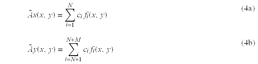
  • a known group of models are linear motion models, in which motion vectors are approximated by linear combinations of motion field basis functions.
  • parameters c i are called motion coefficients and are transmitted to the decoder.
  • Functions f i (x,y) are called motion field basis functions and they have a fixed form known to both encoder and decoder.
  • the problem when using the linear motion model having the above described formula is how to minimise in a computationally simple manner the number of motion coefficients c i which are sent to the decoder, keeping at the same time some measure of distortion, e.g. a chosen measure of prediction error E n (x,y), as low as possible.
  • the total amount of motion data which needs to be sent to the decoder depends both on the number of segments in the image and the number of motion coefficients per segment. Therefore, there exist at least two ways to reduce the total amount of motion data.
  • the first way is to reduce the number of segments by combining (merging) together those segments which can be predicted with a common motion vector field model without causing a large increase of prediction error.
  • the number of segments in the frame can be reduced because very often adjacent, i.e. neighbouring, segments can be predicted well with the same set of motion coefficients.
  • the process of combining such segments is called motion assisted merging.
  • FIG. 3 shows a frame divided into segments.
  • the prior art techniques for motion coefficient coding include several techniques for motion assisted merging. After motion vectors of all the segments have been estimated, motion assisted merging is performed. It is done by considering every pair of adjacent segments S i and S j with their respective motion coefficients c i and c j .
  • the area of combined segments S i and S j is denoted S ij . If the area S ij can be predicted with one set of motion coefficients c ij without causing excessive increase of prediction error over the error resulting from separate predictions of S i and S j , then S i and S j are merged.
  • the methods for motion assisted merging differ essentially in the way of finding a single set of motion coefficients c ij which allow a good prediction of segments combined together.
  • One method is known as merging by exhaustive motion estimation. This method estimates “from scratch” a new set of motion parameters c ij for every pair of adjacent segments S i and S j . If the prediction error for S ij is not excessively increased then the segments S i and S i are merged. Although this method can very well select the segments which can be merged it is not feasible for implementation because it would increase the complexity of the encoder typically by several orders of magnitude.
  • Another method is known as merging by motion field extension. This method tests whether area of S ij can be predicted using either motion parameters c i or c j without an excessive increase of the prediction error. This method is characterised by very low computational complexity because it does not require any new motion estimation. However, it very often fails to merge segments because motion compensation with coefficients calculated for one segment very rarely predicts well also the adjacent segments.
  • Still another method is known as merging by motion field fitting.
  • the motion coefficients c ij are calculated by the method of approximation. This is done by evaluating a few motion vectors in each of the segments. Some motion vectors in segments S i and S j are depicted in FIG. 4 .
  • the motion field for the segment S ij is determined by fitting a common motion vector field through these vectors using some known fitting method.
  • the disadvantage of the method is that the motion field obtained by fitting is not precise enough and often leads to an unacceptable increase of prediction error.
  • the second way to minimise the number of motion coefficients is to select for each segment a motion model which allows achieving satisfactorily low prediction error with as few coefficients as possible. Since the amount and the complexity of the motion varies between frames and between segments it is not efficient to always use all N+M motion coefficients per segment. It is necessary to find out for every segment what is the minimum number of motion coefficients which yields a satisfactorily low prediction error. Such a process of adaptive selection of coefficients is called motion coefficient removal.
  • An object of the present invention is to create a motion compensated video encoder and a method of motion compensated encoding of video data and a video decoder for decoding motion compensation encoded video data, which allow reducing the amount of motion vector field data produced by some known motion estimator by a large factor without causing an unacceptable distortion of the motion vector field.
  • the complexity of the motion field encoder should preferably be low for allowing practical implementation on available signal processors or general purpose microprocessors.
  • an encoder for performing motion compensated encoding of video data comprising:
  • motion field estimating means having an input for receiving a first video data frame I n and a reference frame R ref , said motion field estimating means being arranged to estimate a motion vector field ( ⁇ X, ⁇ Y) describing scene motion displacements of video frame pixels, and having an output for outputting said first video frame, said motion vector field and said reference frame R ref ;
  • motion field encoding means having an input to receive from said motion field estimating means said first estimated motion vector field; partitioning of a video frame into at least two segments said segments being a first segment S i and a second segment S j ; said first video data frame and said reference frame R ref , said motion field encoding means being arranged to obtain compressed motion information comprising first motion coefficients representing said motion vector field;
  • motion compensated prediction means for predicting a predicted video data frame based on said reference frame R ref and said compressed motion information
  • computing means having an input for receiving said first video data frame and said predicted video data frame, said computing means being arranged to calculate a prediction error frame based on said predicted video data frame and on said first video data frame;
  • prediction error encoding means for encoding said prediction error frame
  • orthogonalising means receiving one of said matrices A, B and B′ as an input matrix M, said orthogonalising means being arranged to replace said polynomial basis functions with f i by orthogonal basis functions ⁇ tilde over (f) ⁇ i and to calculate second motion coefficients ⁇ tilde over (c) ⁇ using said orthogonal basis functions and said input matrix M;
  • quantisation means having an input for receiving said second motion coefficients ⁇ tilde over (c) ⁇ , said quantisation means being arranged to quantise said second coefficients ⁇ tilde over (c) ⁇ .
  • an encoder for performing motion compensated encoding of video data comprising:
  • motion field estimating means having an input for receiving a first video data frame I n and a reference frame R ref , said motion field estimating means being arranged to estimate a motion vector field ( ⁇ X, ⁇ Y) describing scene motion displacements of video frame pixels and having an output to output said first video frame, said motion vector field and said reference frame R ref ;
  • motion field encoding means having an input to receive from said motion field estimating means said first estimated motion vector field; partitioning of a video frame into at least two segments said segments being a first segment S i and a second segment S j ; said first video data frame and said reference frame R ref , said motion field encoding means being arranged to obtain compressed motion information comprising first motion coefficients representing said motion vector field;
  • motion compensated prediction means for predicting a predicted video data frame based on said reference frame R ref and said compressed motion information
  • computing means having an input for receiving said first video data frame and said predicted video data frame, said computing means being arranged to calculate a prediction error frame based on said predicted video data frame and on said first video data frame;
  • prediction error encoding means for encoding said prediction error frame
  • orthogonalising means receiving one of said matrices A, B and B′ as an input matrix M, said orthogonalising means being arranged to replace said polynomial basis functions with f i by orthogonal basis functions ⁇ tilde over (f) ⁇ i and to modify said input matrix to a third matrix ⁇ tilde over (M) ⁇ coressponding to said orthogonal basis functions;
  • removing means having an input for receiving of said third matrix ⁇ tilde over (M) ⁇ , said removing means being arranged to modify said third matrix by removing from said third matrix the ith column due to R corresponding to the i th basis functions of said basis functions, and said removing means have an output to provide a matrix ⁇ circumflex over (M) ⁇ ;
  • quantisation means having an input for receiving said second motion coefficients ⁇ tilde over (c) ⁇ , said quantisation means being arranged to quantise said second motion coefficients ⁇ tilde over (c) ⁇ .
  • a Method of motion compensated encoding of video data comprising the steps:
  • a method of motion compensated encoding of video data comprising the steps:
  • orthogonalising means being arranged to replace said polynomial basis functions with f i by orthogonal basis functions ⁇ tilde over (f) ⁇ i and to modify said input matrix to a third matrix ⁇ tilde over (M) ⁇ coressponding to said orthogonal basis functions;
  • a video decoder for decoding of motion compensation encoded video data is characterised by said decoder comprising:
  • said means for predicting a video data frame comprising:
  • a system for handling video data comprising an encoder for performing motion compensated encoding of video data and a decoder for decoding said motion compensated encoding of video data, according to a first aspect of the invention, is characterised by said encoder comprising:
  • motion field estimating means having an input for receiving a first video data frame I n and a reference frame R ref , said motion field estimating means being arranged to estimate a motion vector field ( ⁇ X, ⁇ Y) describing scene motion displacements of video frame pixels, and having an output for outputting said first video frame, said motion vector field and said reference frame R ref ;
  • motion field encoding means having an input to receive from said motion field estimating means said first estimated motion vector field; partitioning of a video frame into at least two segments said segments being a first segment S i and a second segment S j ; said first video data frame and said reference frame R ref , said motion field encoding means being arranged to obtain compressed motion information comprising first motion coefficients representing said motion vector field;
  • motion compensated prediction means for predicting a predicted video data frame based on said reference frame R ref and said compressed motion information
  • computing means having an input for receiving said first video data frame and said predicted video data frame, said computing means being arranged to calculate a prediction error frame based on said predicted video data frame and on said first video data frame;
  • prediction error encoding means for encoding said prediction error frame
  • said motion encoding means further comprising:
  • orthogonalising means receiving one of said matrices A, B and B′ as an input matrix M, said orthogonalising means being arranged to replace said polynomial basis functions with f i by orthogonal basis functions ⁇ tilde over (f) ⁇ i and to calculate second motion coefficients ⁇ tilde over (c) ⁇ using said orthogonal basis functions and said input matrix M;
  • quantisation means having an input for receiving said second motion coefficients ⁇ tilde over (c) ⁇ , said quantisation means being arranged to quantise said second coefficients ⁇ tilde over (c) ⁇ ; and said decoder comprising:
  • said means for predicting a video data frame further comprising:
  • a system for handling video data comprising an encoder for performing motion compensated encoding of video data and a decoder for decoding said motion compensated encoding of video data, according to a second aspect of the invention, is characterised by said encoder comprising:
  • motion field estimating means having an input for receiving a first video data frame I n and a reference frame R ref , said motion field estimating means being arranged to estimate a motion vector field ( ⁇ X, ⁇ Y) describing scene motion displacements of video frame pixels and having an output to output said first video frame, said motion vector field and said reference frame R ref ;
  • motion field encoding means having an input to receive from said motion field estimating means said first estimated motion vector field; partitioning of a video frame into at least two segments said segments being a first segment S i and a second segment S j ; said first video data frame and said reference frame R ref , said motion field encoding means being arranged to obtain compressed motion information comprising first motion coefficients representing said motion vector field;
  • motion compensated prediction means for predicting a predicted video data frame based on said reference frame R ref and said compressed motion information
  • computing means having an input for receiving said first video data frame and said predicted video data frame, said computing means being arranged to calculate a prediction error frame based on said predicted video data frame and on said first video data frame;
  • prediction error encoding means for encoding said prediction error frame
  • said motion encoding means further comprising:
  • orthogonalising means receiving one of said matrices A, B and B′ as an input matrix M, said orthogonalising means being arranged to replace said polynomial basis functions with f i by orthogonal basis functions ⁇ tilde over (f) ⁇ i and to modify said input matrix to a third matrix ⁇ tilde over (M) ⁇ coressponding to said orthogonal basis functions;
  • removing means having an input for receiving of said third matrix ⁇ tilde over (M) ⁇ , said removing means being arranged: to modify said third matrix by removing from said third matrix the i th column due to R corresponding to the i th basis functions of said basis functions, and said removing means have an output to provide a matrix ⁇ circumflex over (M) ⁇ ;
  • quantisation means having an input for receiving said second motion coefficients ⁇ tilde over (c) ⁇ , said quantisation means being arranged to quantise said second motion coefficients ⁇ tilde over (c) ⁇ and to output said second motion coefficients after quantisation; and said decoder comprising:
  • said means for predicting a video data frame comprising:
  • the encoder can perform merging of segments and find for a merged segment, in a computationally efficient way, a set of motion coefficients minimising a measure of distortion.
  • This aspect of the invention also allows a simple and efficient evaluation of distortion due to segment merging, if desired.
  • the encoder according to this aspect performs adaptive merging of adjacent segments of a video frame by means of calculating an additional distortion according to a predefined measure and merging the segments if the additional distortion is tolerable, e.g. below a given threshold or tolerable with regard to an achieved bit rate reduction.
  • a chosen measure for calculating this distortion can be, but is not limited to, some measure of prediction error, for instance the energy or squared prediction error in the segment.
  • Another measure of distortion can be e.g. the squared difference between an original frame and the restored original frame after encoding and decoding.
  • the motion field encoder included in the video encoder comprises three main blocks.
  • the first main block may be called a QR motion analyser. Its task is to find a new representation of the inputted motion vector field produced by the motion field estimator. This new representation is applied to the second main block.
  • Operations in this first main block include a plurality of steps comprising matrix operations:
  • the prediction frame is linearised using some known approximation method so that the prediction frame becomes a linear function of the motion vectors.
  • a matrix E i and a matrix y i are constructed for minimisation of an appropriate measure of prediction error, e.g. the square prediction error.
  • Matrix E i is decomposed into a product of two matrices Q i and R i .
  • an auxiliary vector z i is calculated from the factor matrix Q i and the matrix y i . Part of the matrix R i and the auxiliary vector z i are applied to the second main block.
  • the second main block performs merging operations for pairs of segments S i , S j .
  • this block checks whether the motion in the combined area of S i and S j can be predicted using a common motion field model for the combined area.
  • a matrix equation is firstly formed based on said factor matrices, thereafter the factor matrices are processed by using known matrix computation methods.
  • the result is a matrix equation which allows calculation of motion coefficients common for the pair of segments under consideration, in a simple and efficient way. Using these coefficients the chosen measure of distortion can be calculated in the area of the merged segments.
  • the square prediction error is used as the measure of distortion, it can be easily calculated on the basis of the terms included in one of the resulting matrices. If the change of said measure of prediction error is acceptable according to a chosen criterion, the segments are merged. It will be appreciated that no merging occurs if merging of segments would cause excessive distortion to the prediction.
  • the output of the segment merging block is a new segmentation of the image with a reduced number of segments. Moreover, for each new segment the block outputs a matrix R k 1 and a vector z k 1 , which allow calculation of all motion coefficients in a simple and efficient way. Also, the encoder provides the decoder with information enabling the reconstruction of the resulting new segments in the frame.
  • the segment merging block allows a computationally simple judgement whether segments can be merged into one. Merging of as many segments as possible can be achieved by judging for each pair of adjacent segments whether merging is possible, and repeating this process for the resulting segmentation of the frame until no pair of adjacent segments suitable for merging remains in the frame.
  • the amount of distortion introduced by the segment merging can be calculated based on a linear approximation of additional distortion due to approximating the motion vector field by a linear combination of basis functions.
  • the third main block is called an orthogonalisation block. This block receives as its input the partitioning of the current frame into segments and for every segment S k matrices R k 1 and Z k 1 from the segment merging block.
  • the block replaces the polynomial basis functions which describe the motion vectors of the image segments by orthogonal polynomials. Orthogonalisation leads to a motion field model which is less sensitive to quantisation errors resulting from quantising the motion coefficients and to representation of the motion vector field with fewer bits.
  • an encoder includes a fourth main block, which allows removing coefficients from the set of coefficients representing the motion vector field of a segment and finding, in a computationally efficient way, the optimum remaining coefficients having regard to a measure of distortion. Also, if desired, the invention according to this aspect enables checking whether the omission of a particular coefficient of this set causes a significant increase of distortion in the motion field or not. This check is performed in a computationally efficient way such that for each segment each coefficient of the set may be subjected to such checking. It is only necessary to transmit those coefficients to the decoder that are found to increase the distortion significantly if omitted.
  • An encoder comprises a first main block operating in a similar way to the first main block of the first aspect of the invention. It furthermore comprises a second main block equivalent to the fourth main block of the second aspect.
  • the second main block receives for every segment S i a matrix R i and a vector z i produced by the first block. If desired, the second main block determines based on matrix R i and vector z i for each of the segments whether it is possible to simplify the motion field model by removing basis functions from the model without intolerable increase of distortion.
  • the coefficient removal block For every segment processed, the coefficient removal block outputs segment selection information which tells which basis functions were removed from the motion field model. Additionally, it outputs new motion coefficients corresponding to the remaining basis functions. Both selection information and motion coefficients are transmitted to the decoder.
  • the encoder may instead of outputting the selection information followed by motion coefficients, output all motion coefficients with coefficients corresponding to removed basis functions having values equal to zero.
  • a motion compensated video encoder takes advantage of adaptively merging segments, orthogonalising the output of segment merging and removing motion coefficients which are not significant for the overall distortion.
  • a preferred encoder includes all four blocks previously described, namely a QR motion analyser, a segment merging block and an orthogonalisation block according to the first aspect of the invention and also a coefficient removal block according to the second aspect of the invention.
  • the orthogonalisation block receives the current partitioning of segments and for every segment S k it also receives matrices R k 1 and Z k 1 from the segment merging block and orthogonalises the motion field model with respect to the segments obtained from segment merging.
  • the coefficient removal block then receives for every segment S k matrices ⁇ tilde over (R) ⁇ k 1 and ⁇ tilde over (Z) ⁇ k 1 produced by the orthogonalisation block. Only after merging of adjacent segments and after manipulating matrix R 1 and vector z 1 for coefficient removal, the coefficients c i of each segment are calculated for transmission, resulting in a substantial reduction in the amount of motion data output by the video encoder.
  • a video encoder and decoder according to the present invention is implemented in hardware, e.g. as one or more integrated circuits, adapted to perform encoding and compressing of received video frames, and decoding encoded video data, respectively, according to the present invention.
  • some of the video frame areas are coded without using any temporal prediction at all (so called intra-blocks). No motion coefficients are transmitted for such image areas and the areas are coded without reference to any prior images. Practical embodiments of the present invention would also combine the invention with such intra-coding.
  • the encoder may decide to use the better of these predictions, or it may decide to combine the two predictions (e.g., by averaging).
  • the decision regarding the mode needs to be communicated to the decoder.
  • the ITU H.263 standard also includes a temporal prediction mode using two reference frames. It is clear that the present invention can benefit from similar techniques of using multiple reference frames.
  • the present invention can be the basis for one or more coding modes in a video codec where it is used together with prior art coding modes (such as intra coding, stationary modes, or multiple reference frames).
  • FIG. 1 is a schematic diagram of a known encoder
  • FIG. 2 is a schematic diagram of a known decoder
  • FIG. 3 depicts adjacent segments for merging
  • FIG. 4 illustrates merging by motion field approximation
  • FIG. 5 is a motion field coder according to the preferred embodiment of the present invention.
  • FIG. 6 is a schematic diagram of a QR motion analyser
  • FIG. 7 is a schematic diagram of a motion compensated prediction block according to an embodiment of the present invention.
  • FIG. 8 is a block diagram of a decoder according to an embodiment of the present invention.
  • the motion coefficients represent a compressed motion vector field [ ⁇ tilde over ( ⁇ ) ⁇ x( ⁇ ), ⁇ tilde over ( ⁇ ) ⁇ y( ⁇ )] which approximates [ ⁇ x(x,y), ⁇ y(x,y)] as precisely as necessary using a linear motion model of the form:
  • SPE square prediction error SPE
  • FIG. 5 illustrates an embodiment of a motion field encoder in a video encoder according to the invention. It corresponds to block 3 in FIG. 1 but its inputs also include the reference frame and the current frame.
  • the third input to this block is the motion vector field [ ⁇ x( ⁇ ), ⁇ y( ⁇ )] produced by motion field estimation block 2 , FIG. 1 .
  • the motion field encoder 3 consists of four main building blocks which are the QR motion analyser block 31 , the segment merging block 32 , orthogonalisation block 32 b and motion coefficient removal block 33 .
  • the segment merging block 32 , orthogonalisation block 32 b and the motion coefficient removal block 33 reduce the amount of motion information which may result in a less accurate prediction and hence an increase of the square prediction error.
  • FIG. 6 shows an embodiment of the QR motion analyser according to this invention.
  • This block comprises a gradient filter 41 receiving a reference video frame input R ref .
  • the outputs G x , G y of the gradient filter are input into a block 42 for building a matrix E and into a block 45 for building a vector y.
  • Matrix building block 42 performs a linearisation of the reference frame R ref such that the approximated reference frame is a linear function of ⁇ tilde over ( ⁇ ) ⁇ x and ⁇ tilde over ( ⁇ ) ⁇ y and calculates on the basis of this linearisation a matrix E, the multiplication of which with a vector c of coefficients c i in equations 4 a , 4 b above may be interpreted as prediction error resulting if ⁇ x, ⁇ y are replaced by a linear combination of basis functions f i (x,y) of a linear motion model.
  • Block 45 for building vector y receives the current frame I n , reference frame R ref , the outputs G x , G y of the gradient filter 41 and the motion vectors [ ⁇ x(x,y), ⁇ y(x,y)] estimated by block 2 in FIG. 1 and calculates said vector y from these inputs.
  • Matrix E and vector y are received by a QR factoriser block 43 and a matrix multiplier block 46 , respectively.
  • the function of these blocks can be regarded as a coordinate transformation of matrix E and vector y in order to prepare for finding coefficients c i such that for all pixels of a given segment the prediction error resulting from the representation of ⁇ x, ⁇ y as a linear combination of basis functions f i is as close as possible to the inherent prediction error. This will be explained in further detail below.
  • Block 43 outputs a matrix R which results from representing matrix E in the coordinates of a matrix Q also output by block 43 .
  • Block 46 receives not only said vector y but also said matrix Q from block 43 and finds a vector z representing y in the coordinates of matrix Q.
  • matrix Q is orthonormal.
  • this representation of E and y as R and z, respectively is very advantageous for judging whether adjacent segments can be merged with tolerable increase of prediction error, and also for finding the minimum number of coefficients necessary for representing the motion vector field of a merged or non-merged segment, i.e. for removing non-significant coefficients from the set of coefficients c i in equations 4 a , 4 b.
  • Blocks 44 and 47 receive matrix R and vector z, respectively and select rows from these which are required for judging the effect of segment merging and/or motion coefficient removal. These operations are performed based on R and z without the need of calculating said coefficients c i . Furthermore, all row manipulations refer both to the rows of R and to the corresponding rows of z such that R and z can be regarded for the purpose of segment merging and/or motion coefficient removal as a single column extended matrix A comprising the columns of R and comprising as an additional column, vector z. Accordingly, blocks 44 and 47 can be regarded and implemented as one block for manipulating matrix A by selecting appropriate rows of A and for outputting a modified matrix A′ comprising the selected rows of A. A′ comprises the selected rows denoted R 1 of R and the selected rows denoted z 1 of z.
  • Segment merging block 32 receives R 1 and z 1 , i.e. matrix A′, for each segment and judges whether merging of two segments S i , S j by means of representing the motion vector fields of both segments with the same set of coefficients, results in a tolerable increase of prediction error. This is done by means of generating a row extended matrix B comprising all rows of matrix A′ i of segment S i and of matrix A′ j of segment S j . Segments S i , S j can be, but do not have to be, adjacent. Matrix B is subjected to a further coordinate transformation e.g. by means of triangularisation of matrix B, resulting in a modified matrix B′. Block 32 in FIG.
  • Orthogonalisation block 32 b receives for each segment after frame resegmentation said matrix A′ if the corresponding segment remained unmerged, or matrix B′ for merged segments and merging information from segment merging block 32 .
  • Block 32 b modifies matrices A′ or B′ by replacing the polynomial basis functions which represent the motion vectors of such a segment with orthogonal polynomials.
  • the modified matrices together with the segmentation information, are output to block 33 .
  • the modified matrices are denoted by ⁇ 1 and ⁇ tilde over (B) ⁇ 1 , respectively, depending on whether they originate from unmerged or merged segments.
  • the motion coefficient removal block 33 in FIG. 5 receives said matrix ⁇ 1 if the corresponding segment remained unmerged, or matrix ⁇ tilde over (B) ⁇ 1 for merged segments and judges whether removal of coefficients c i is possible with a tolerable increase of prediction error. This is performed by block 33 by means of extracting a row from matrix ⁇ 1 or ⁇ tilde over (B) ⁇ 1 , respectively, i.e. the row corresponding to coefficient c i .
  • the additional prediction error introduced due to removing a coefficient can then be calculated from a selected element of said transformed matrix, said selected element being located in the column resulting from z 1 of said transformed matrix and in the row of this matrix which has zeros in all columns resulting from R 1 .
  • Multiplexer 34 in FIG. 5 receives merging information from block 32 , information about which coefficients c i are selected for transmission, and the selected coefficients c i which are finally calculated based on said transformed matrix produced by block 33 .
  • the information transmitted by multiplexer 34 is then output to the video decoder (not shown).
  • Step 1 is linearisation of the prediction error.
  • the reference frame R ref in equation (5) is approximated using some known approximation method so that it becomes linear with respect to [ ⁇ tilde over ( ⁇ ) ⁇ x( ⁇ ), ⁇ tilde over ( ⁇ ) ⁇ y( ⁇ )].
  • ⁇ tilde over ( ⁇ ) ⁇ x ( x,y ) c 1 +c 2 x+c 3 y+c 4 xy+c 5 x 2 +c 6 y 2 (7a)
  • ⁇ tilde over ( ⁇ ) ⁇ y ( x,y ) c 7 +c 8 x+c 9 y+c 10 xy+c 11 x 2 +c 12 y 2 (7b)
  • x′ i x i + ⁇ x( x i ,y i )
  • function f j (x i ,y i ) is a predefined basis function according to the motion field model as defined in equations ( 4 a ) and ( 4 b ) and more specifically, in equations ( 7 a ) and ( 7 b ).
  • G x (x,y) and G y (x,y) are values of the horizontal and vertical gradients of the reference frame R ref (x,y) calculated using following formula:
  • the pixel values of R ref (x,y), G x (x,y) and G y (x,y) are defined only for integer coordinates x and y.
  • the pixel value is calculated e.g. using a bilinear interpolation of closest pixels with integer coordinates.
  • Step 3 is QR Factorisation.
  • QR factorisation of a matrix is as such well known and a suitable algorithm is described in D. H. Golub and C. van Loan, “Matrix computation” 2nd edition, The Johns Hopkins University Press, 1989. This algorithm can be used to decompose matrix E into a product of two matrices
  • R is a representation of E in coordinates of Q.
  • Q is preferably orthonormal and such that R is upper triangular, i.e. rows N+M+1 to P of R are all zero.
  • step 4 the output of the QR motion analyser block is calculated.
  • the output comprises a matrix R 1 consisting of the N+M first rows of matrix R and a vector z 1 consisting of the first N+M elements of z.
  • the merging operation is performed for pairs of adjacent segments S i and S j , see FIG. 4, by judging whether for a combined segment S ij the motion vector field can be represented using a common motion field described by motion coefficient vector c ij .
  • the merging operation consists of the following steps:
  • Step 1 comprises matrix calculation.
  • This invention utilises a previously unknown property that motion coefficient vector c ij minimising the prediction error in the merged segment S ij also minimise the scalar value ( [ R i 1 R j 1 ] ⁇ c ij - [ z i 1 z j 1 ] ) T ⁇ ( [ R i 1 R j 1 ] ⁇ c ij - [ z i 1 z j 1 ] ) ( 11 )
  • the system of equation (13) is triangularised by applying a series of multiplications of rows by scalars followed by additions of the rows; i.e. it is converted to the form: [ r 1 , 1 r 1 , 2 r 1 , 3 ... r 1 , N + M 0 r 2 , 2 r 2 , 3 ... r 2 , N + M 0 0 r 3 , 3 ... r 3 , N + M 0 0 0 ⁇ ⁇ 0 0 0 0 r N + M , N + M 0 0 0 0 0 0 0 0 r N + M , N + M 0 0 0 0 0 0 0 0 0 0 0 0 0 0 0 0 0 0 0 0 0 0 0 0 0 0 0 0 0 0 0 0 0 0 0 0 0 0 0
  • QR factorisation according to said document mentioned above may be used.
  • step 3 the merging error is evaluated.
  • QR factorisation of (13) results in Q being orthonormal, such that equation 15 is very simple.
  • step 4 the segments are merged if the change of square prediction error in formula (15) is acceptable according to a chosen criterion.
  • the segment merging block uses the following strategy for segment merging:
  • a threshold t is selected which corresponds to the allowed increase of square prediction error in the whole frame
  • steps b-c are repeated until the sum of ⁇ E ij corresponding to all merged pairs of segments is greater than t.
  • the output of the segment merging block is obtained.
  • the output comprises three kinds of information. Firstly, it gives a new division of the image with a reduced number of segments. Secondly, for each new segment the block outputs matrix R k 1 and vector z k 1 . Thirdly, it gives merging information which is sent to the decoder and helps the decoder to identify segments which were merged.
  • equations 4a and 4b are fully equivalent to the one in equations 17a and 17b, the latter is used because coefficients ⁇ tilde over (c) ⁇ i are less sensitive to quantisation than c i and hence can be represented with fewer bits.
  • orthogonalisation algorithms e.g. the Gramm-Schmidt algorithm
  • Gramm-Schmidt algorithm can be used to convert ordinary polynomials to polynomials orthogonal in an arbitrary shaped segment area.
  • it is computationally much less complex to orthogonalise the motion field basis functions with respect to the rectangle circumscribing the given segment.
  • Orthogonalisation with respect to the rectangle circumscribing the given segment can be performed as follows. For a rectangle of N 1 ⁇ N 2 pixels two sequences of one dimensional polynomials, e.g Legendre polynomials, are computed:
  • the coefficient removal block 33 receives as its input said new division of the current frame into segments and for every segment S k it receives said matrices ⁇ tilde over (R) ⁇ k 1 , ⁇ tilde over (z) ⁇ k 1 , produced previously by the orthogonalisation block.
  • Motion vectors of every segment are represented by N+M motion coefficients, N and M being determined by the motion field model for ⁇ x and ⁇ y.
  • the motion coefficient removal block 33 determines for a given segment S k whether it is possible to simplify the motion field model, without excessively increasing the prediction error.
  • a simplified motion field model is obtained when some basis functions are removed from the model in equations (17a) and (17b) and fewer coefficients are required to describe such a simplified motion field model.
  • Step 1 includes a matrix modification, where the system of linear equations (24)
  • Step 2 includes a matrix triangularisation, preferably using said QR factorisation algorithm described in the above-mentioned document, or using a sequence of Givens rotations. That is, the system in equation (24) is triangularised in a manner known as such, by applying a series of multiplications of rows by scalars followed by additions of the rows, i.e.
  • Step 3 includes error evaluation.
  • the change of the square prediction error for the segment caused by removal of the i th coefficient is simply equal to the term ⁇ tilde over (q) ⁇ 2 i in equation (25). Again, this is valid based on Q in said QR factorisation being orthonormal. In general, depending on the properties of Q and the measure for prediction error, the change of the square prediction error is a function of ⁇ tilde over (q) ⁇ i .
  • Step 4 includes removal of coefficients. If the change of the prediction error is acceptable according to a chosen criterion then the coefficient c i is removed from the coefficient vector. The new number of coefficients is now N+M ⁇ 1. Matrix ⁇ tilde over (R) ⁇ k 1 and vector ⁇ tilde over (z) ⁇ k 1 are modified e.g.
  • R ⁇ k 1 [ r ⁇ 1 , 1 r ⁇ 1 , 2 r ⁇ 1 , 3 ... r ⁇ 1 , N + M - 1 r ⁇ 2 , 2 r ⁇ 2 , 3 ... r ⁇ 2 , N + M - 1 r ⁇ 3 , 3 ... r ⁇ 3 , N + M - 1 ⁇ ⁇ r ⁇ N + M - 1 , N + M - 1 ]
  • z ⁇ k 1 [ z ⁇ 1 z ⁇ 2 z ⁇ 3 ⁇ z ⁇ N + M - 1 ] ( 26 )
  • the number of coefficients for the segment can be reduced further by repeating the steps 1-4 based on equation (26).
  • a threshold t is selected which corresponds to an allowed increase of square prediction error in the whole frame
  • steps b-c are repeated until the sum of all ⁇ tilde over (q) ⁇ i 2 terms corresponding to all removed basis functions in different segments is greater than t.
  • step 5 includes coefficient calculation. After removal of suitable coefficients in this step the final motion coefficients for a segment S k are calculated by solving the system of linear equations (24):
  • FIG. 7 shows an embodiment of motion compensated prediction block 1 of FIG. 1 .
  • This block receives motion information output by motion field coding block 3 and furthermore receives a reference frame R ref (x,y). Based on this information, block 1 outputs a predicted frame P n (x,y).
  • motion compensated prediction bock 1 comprises a demultiplexer 11 receiving multiplexed motion information from motion field encoding block 3 and outputting demultiplexed motion information components, i.e. image partitioning information, coefficient selection information and, finally, the value of the transmitted motion coefficients.
  • Reference numeral 12 denotes an image partitioning block receiving said image partitioning information and said reference frame R ref and outputting segments of the frame resulting from partitioning the image according to the image partitioning information.
  • Reference numeral 13 denotes a basis functions building block. This block selects from a predefined set of basis functions the particular basis functions indicated in the selection information generated by the motion coefficient removal block 33 in motion field encoding block 3 .
  • Reference numeral 14 denotes a segment prediction block which receives for each segment of said reference frame R ref the associated selection of basis functions and the associated motion coefficients, calculates the motion vectors [ ⁇ tilde over ( ⁇ ) ⁇ x, ⁇ tilde over ( ⁇ ) ⁇ y] and based on these motion vectors, calculates the predicted frame P n (x,y) for each pixel (x,y) of each segment.
  • Motion compensated prediction block 1 corresponds in its structure and function to motion compensated prediction block 21 of the video decoder depicted in FIG. 2 . Both motion compensated prediction blocks base the prediction on the motion information output by motion field coding block 3 of the video encoder shown in FIG. 1 .
  • FIG. 8 is a block diagram of a motion compensated prediction block according to an embodiment of the present invention.
  • the figure shows the main blocks of an decoder according, comprising:
  • means 82 for predicting a video data frame based on said stored video data frame and on received motion information
  • means 85 for calculating and outputting an updated video data frame based on said predicted video data frame and said decoded prediction error frame, and storing the updated video data frame in said storing means;
  • said means for predicting a video data frame comprising
  • means 11 for demultiplexing received motion data into at least two of the following: data concerning the partitioning of said updated video data frame into segments S i , data concerning a selection of basis functions from a set of motion field model basis functions, and data concerning coefficients of selected basis functions;
  • means 83 for calculating said prediction frame based on said reconstructed motion vector field and based on said stored video data frame.
  • the motion field encoder produces merging information for informing the decoder which segments are merged, selection information informing the decoder which basis functions are removed and motion coefficient information.
  • the main advantage of the present invention over prior art solutions is its ability to reduce the amount of motion information by a large factor without causing a large increase of prediction error. Additionally the complexity of the overall system is low which allows practical implementation on available signal processors or general purpose microprocessors.
  • the segment merging block has the ability of finding motion vectors of combined segments from given motion vectors estimated for separate segments. It can be proven that the motion vectors it produces are in fact optimal in terms of maintaining low square error for the combined segment. This explains the ability of this block to dramatically reduce the number of segments with only very modest increase of square prediction error.
  • orthogonalisation block provides a motion field model which is less sensitive to quantisation errors and therefore fewer bits can be used to quantise the motion coefficients.
  • the motion coefficient removal block is a very powerful tool for instantaneous adaptation of the motion model to the actual amount and type of motion in the video scene.
  • This block can easily test the result of prediction (value of square prediction error for a segment) with a very large number of models, e.g., with all possible combinations of motion field basis functions.
  • a strong advantage of this scheme is that it does not need to repeat the process of motion estimation and hence is computationally simple.
  • the motion field coder can find new motion coefficients for any desired combination of image segments or any desired model of the motion field in the segment by solving very simple systems of linear equations.
  • segment merging, orthogonalisation and coefficient removal blocks are preferably combined to provide a greater degree of motion data reduction with a small reduction of image quality.
  • the system can be implemented in a variety of ways without departing from the spirit and the scope of the invention.
  • different linear motion models can be used in equation (3). Different methods can be used to linearise the term in the formula (5). Further, different criteria may be used to decide whether to merge or not to merge two segments. The strategy for deciding whether a given basis function should be removed from the model may vary. Triangularisation of matrices in equations (12) and (24) can be performed using various algorithms and calculation of final coefficients by solving equation (24) can be done using a number of known algorithms for solving systems of linear equations. Different interpolation methods may also be used to determine the values of R ref (x,y), G x (x,y) and G y (x,y) at non-integer coordinates.

Abstract

This invention relates to motion compensated (MC) coding of video and to a MC prediction scheme which allows fast and compact encoding of motion vector fields retaining at the same time very low prediction error. By reducing prediction error and number of bits needed for representation of motion vector field, substantial savings of bit rate are achieved. Reduction of bit rate needed to represent motion field is achieved by merging segments in video frames, by adaptation of motion field model and by utilization of motion field model based on orthogonal polynomials.

Description

FIELD OF THE INVENTION
The present invention generally relates to video compression. More precisely, the invention relates to an encoder and method for performing motion compensated encoding of video data. The invention also relates to a decoder for decoding video data thus encoded.
BACKGROUND OF THE INVENTION
Motion compensated prediction is a key element of the majority of video coding schemes. FIG. 1 is a schematic diagram of an encoder for compression of video sequences using motion compensation. Essential elements in the encoder are a motion compensated prediction block 1, a motion estimator 2 and a motion field coder 3. The operating principle of the motion compensating video encoder is to compress the prediction error En(x,y), which is a difference between the incoming frame In(x,y) to be coded, called the current frame, and a prediction frame Pn(x,y), wherein:
En(x,y)=In(x,y)−Pn(x,y)  (1)
Compression of the prediction error En(x,y) typically introduces some loss of information. The compressed prediction error, denoted {tilde over (E)}n(x,y), is sent to the decoder. The prediction frame Pn(x,y) is constructed by the motion compensated prediction block 1 and is built using pixel values of the previous, or some other already coded frame denoted Rref(x,y), called a reference frame, and motion vectors describing estimated movements of pixels between the current frame and the reference frame. Motion vectors are calculated by motion field estimators 2 and the resulting motion vector field is then coded in some way before applying it to the predictor block 1. The prediction frame is then:
Pn(x,y)=Rref [x+Δx(x,y),y+Δy(x,y)]  (2)
The pair of numbers [Δx(x,y), Δy(x,y)] is called the motion vector of a pixel in location (x,y) in the current frame, whereas Δx(x,y) and Δy(x,y) are the values of horizontal and vertical displacement of this pixel. The set of motion vectors of all pixels in the current frame In(x,y) is called motion vector field. The coded motion vector field is also transmitted as motion information to the decoder.
In the decoder shown in FIG. 2, pixels of the current frame In(x,y) are reconstructed by finding the pixels' predictions Pn(x,y) from the reference frame Rref(x,y). The motion compensated prediction block 21 generates the prediction frame using the received motion information and the reference frame Rref(x,y). In the prediction error decoder 22 a decoded prediction error frame {tilde over (E)}n(x,y) is then added with the prediction frame, the result being the approximated current frame Ĩn.
The general object of the motion compensated (MC) prediction encoder is to minimise the amount of information which needs to be transmitted to the decoder. It should minimise the amount of prediction error measured according to some criteria, e.g. the energy associated with En(x,y), and minimise the amount of information needed to represent the motion vector field.
The document N. Nguen, E. Dubois, “Representation of motion information for image coding”. Proc. Picture Coding Symposium '90, Cambridge, Mass., Mar. 26-18, 1990, pages 841-845, gives a review of motion field coding techniques.
As a rule of the thumb, a reduction of prediction error requires a more refined sophisticated motion field, i.e. more bits must be spent on its encoding. Therefore the overall goal of the video encoding is to encode the motion vector field as compactly as possible keeping at the same time the measure of prediction error as low as possible.
Due to the very large number of pixels in the frame, it is not efficient to transmit a separate motion vector for each pixel. Instead, in most of the video coding schemes the current frame is divided into image segments, as shown for example in FIG. 3, so that all motion vectors of the segment can be described by a few parameters. Image segments can be square blocks. For example 16×16 pixel blocks are used in codecs in accordance with international standard ISO/IEC MPEG-1 or ITU-T H.261, or they can comprise completely arbitrarily shaped regions obtained for instance by a segmentation algorithm. In practice segments include at least a few tens of pixels.
The motion field estimation block 1 of FIG. 1 calculates motion vectors of all the pixels of a given segment which minimise some measure of prediction error in this segment, for example the square prediction error. Motion field estimation techniques differ both in the model of the motion field and in the algorithm for minimisation of the chosen measure of prediction error.
In order to compactly represent the motion vectors of the pixels in the segments it is desirable that their values are described by a function of few parameters. Such a function is called a motion vector field model. A known group of models are linear motion models, in which motion vectors are approximated by linear combinations of motion field basis functions. In such models the motion vectors of image segments are described by a general formula: Δ x ( x , y ) = i = 1 N c i f i ( x , y ) Δ y ( x , y ) = i = N + 1 N + M c i f i ( x , y ) ( 3 )
Figure US06212235-20010403-M00001
where parameters ci are called motion coefficients and are transmitted to the decoder. Functions fi(x,y) are called motion field basis functions and they have a fixed form known to both encoder and decoder.
The problem when using the linear motion model having the above described formula is how to minimise in a computationally simple manner the number of motion coefficients ci which are sent to the decoder, keeping at the same time some measure of distortion, e.g. a chosen measure of prediction error En(x,y), as low as possible.
The total amount of motion data which needs to be sent to the decoder depends both on the number of segments in the image and the number of motion coefficients per segment. Therefore, there exist at least two ways to reduce the total amount of motion data.
The first way is to reduce the number of segments by combining (merging) together those segments which can be predicted with a common motion vector field model without causing a large increase of prediction error. The number of segments in the frame can be reduced because very often adjacent, i.e. neighbouring, segments can be predicted well with the same set of motion coefficients. The process of combining such segments is called motion assisted merging. FIG. 3 shows a frame divided into segments. The prior art techniques for motion coefficient coding include several techniques for motion assisted merging. After motion vectors of all the segments have been estimated, motion assisted merging is performed. It is done by considering every pair of adjacent segments Si and Sj with their respective motion coefficients ci and cj. The area of combined segments Si and Sj is denoted Sij. If the area Sij can be predicted with one set of motion coefficients cij without causing excessive increase of prediction error over the error resulting from separate predictions of Si and Sj, then Si and Sj are merged. The methods for motion assisted merging differ essentially in the way of finding a single set of motion coefficients cij which allow a good prediction of segments combined together.
One method is known as merging by exhaustive motion estimation. This method estimates “from scratch” a new set of motion parameters cij for every pair of adjacent segments Si and Sj. If the prediction error for Sij is not excessively increased then the segments Si and Si are merged. Although this method can very well select the segments which can be merged it is not feasible for implementation because it would increase the complexity of the encoder typically by several orders of magnitude.
Another method is known as merging by motion field extension. This method tests whether area of Sij can be predicted using either motion parameters ci or cj without an excessive increase of the prediction error. This method is characterised by very low computational complexity because it does not require any new motion estimation. However, it very often fails to merge segments because motion compensation with coefficients calculated for one segment very rarely predicts well also the adjacent segments.
Still another method is known as merging by motion field fitting. In this method the motion coefficients cij are calculated by the method of approximation. This is done by evaluating a few motion vectors in each of the segments. Some motion vectors in segments Si and Sj are depicted in FIG. 4. The motion field for the segment Sij is determined by fitting a common motion vector field through these vectors using some known fitting method. The disadvantage of the method is that the motion field obtained by fitting is not precise enough and often leads to an unacceptable increase of prediction error.
The second way to minimise the number of motion coefficients is to select for each segment a motion model which allows achieving satisfactorily low prediction error with as few coefficients as possible. Since the amount and the complexity of the motion varies between frames and between segments it is not efficient to always use all N+M motion coefficients per segment. It is necessary to find out for every segment what is the minimum number of motion coefficients which yields a satisfactorily low prediction error. Such a process of adaptive selection of coefficients is called motion coefficient removal.
Methods for performing motion estimation with different models and selecting the most suitable one are proposed in H. Nicolas and C. Labit, “Region-based motion estimation using deterministic relaxation schemes for image sequence coding,” Proc. 1994 International Conference on Acoustics, Speech and Signal Processing, pp. III265-268 and P. Cicconi and H. Nicolas, “Efficient region-based motion estimation and symmetry oriented segmentation for image sequence coding,” IEEE Tran. on Circuits and Systems for Video Technology, Vol. 4, No. 3, June 1994, pp. 357-364. The methods try to adapt the motion model depending on the complexity of the motion by performing motion estimation with different models and selecting the most suitable one. The main disadvantage of these methods is their high computational complexity and the small number of different motion field models which can be tested in practice.
Although the afore-described methods reduce the amount of motion information sent to the decoder to some extent while maintaining the accuracy of predicted image at a reasonable level, there is still a desire to further reduce that amount.
SUMMARY OF THE INVENTION
An object of the present invention is to create a motion compensated video encoder and a method of motion compensated encoding of video data and a video decoder for decoding motion compensation encoded video data, which allow reducing the amount of motion vector field data produced by some known motion estimator by a large factor without causing an unacceptable distortion of the motion vector field. The complexity of the motion field encoder should preferably be low for allowing practical implementation on available signal processors or general purpose microprocessors.
According to a first aspect of the invention, an encoder for performing motion compensated encoding of video data, comprising:
motion field estimating means, having an input for receiving a first video data frame In and a reference frame Rref, said motion field estimating means being arranged to estimate a motion vector field (ΔX, ΔY) describing scene motion displacements of video frame pixels, and having an output for outputting said first video frame, said motion vector field and said reference frame Rref;
motion field encoding means having an input to receive from said motion field estimating means said first estimated motion vector field; partitioning of a video frame into at least two segments said segments being a first segment Si and a second segment Sj; said first video data frame and said reference frame Rref, said motion field encoding means being arranged to obtain compressed motion information comprising first motion coefficients representing said motion vector field;
motion compensated prediction means for predicting a predicted video data frame based on said reference frame Rref and said compressed motion information;
computing means having an input for receiving said first video data frame and said predicted video data frame, said computing means being arranged to calculate a prediction error frame based on said predicted video data frame and on said first video data frame;
prediction error encoding means for encoding said prediction error frame;
means for transmitting said first motion coefficients and said prediction error frame to a decoder;
is characterised by said motion encoding means further comprising:
means, for calculating and storing for each segment a distortion matrix E and a distortion vector y such that a predefined measure ΔE for distortion in each segment, due to approximating said motion vector field as coefficients ci of a set of polynomial basis functions fi, is a function of (E c−y), c being a vector of said motion coefficients ci;
means for decomposing said distortion matrix E into a first matrix Q and a second matrix R such that
det Q≠0 and
Q R=E,
 a subset of the set of all columns of matrix Q being a basis of a vector space defined by all possible linear combinations of all column vectors of matrix E, columns of matrix Q being orthogonal to each other;
means for calculating an auxiliary vector z according to z=Q−1 y, Q−1 being the inverse matrix of said first matrix Q;
means for generating for each segment a column extended matrix A comprising the columns of matrix R and vector z as an additional column, and for selecting all rows of matrix A which have elements unequal to zero in all columns due to R;
means for merging segments based on selective combination of segments producing an increase in said prediction error within a certain limit;
means for generating a row extended matrix B comprising said selected rows of matrix A of said first segment Si and said selected rows of matrix A of said second segment Sj;
means for performing a series of multiplications of rows of matrix B with scalars unequal to zero and additions of rows of matrix B in order to obtain a modified matrix B′ having in the columns due to matrix R as many rows as possible filled with zeros;
orthogonalising means receiving one of said matrices A, B and B′ as an input matrix M, said orthogonalising means being arranged to replace said polynomial basis functions with fi by orthogonal basis functions {tilde over (f)}i and to calculate second motion coefficients {tilde over (c)} using said orthogonal basis functions and said input matrix M; and
quantisation means, having an input for receiving said second motion coefficients {tilde over (c)}, said quantisation means being arranged to quantise said second coefficients {tilde over (c)}.
According to a second aspect of the invention, an encoder for performing motion compensated encoding of video data, comprising:
motion field estimating means, having an input for receiving a first video data frame In and a reference frame Rref, said motion field estimating means being arranged to estimate a motion vector field (ΔX, ΔY) describing scene motion displacements of video frame pixels and having an output to output said first video frame, said motion vector field and said reference frame Rref;
motion field encoding means having an input to receive from said motion field estimating means said first estimated motion vector field; partitioning of a video frame into at least two segments said segments being a first segment Si and a second segment Sj; said first video data frame and said reference frame Rref, said motion field encoding means being arranged to obtain compressed motion information comprising first motion coefficients representing said motion vector field;
motion compensated prediction means for predicting a predicted video data frame based on said reference frame Rref and said compressed motion information;
computing means having an input for receiving said first video data frame and said predicted video data frame, said computing means being arranged to calculate a prediction error frame based on said predicted video data frame and on said first video data frame;
prediction error encoding means for encoding said prediction error frame;
means for transmitting said first motion coefficients and said prediction error frame to a decoder;
is characterised by said motion encoding means further comprising:
means, for calculating and storing for each segment a distortion matrix E and a distortion vector y such that a predefined measure ΔE for distortion in each segment, due to approximating said motion vector field as coefficients ci of a set of polynomial basis functions fi, is a function of (E c−y), c being a vector of said motion coefficients ci;
means for decomposing said distortion matrix E into a first matrix Q and a second matrix R such that
det Q≠0, and
Q R=E,
 a subset of the set of all columns of matrix Q being a basis of a vector space defined by all possible linear combinations of all column vectors of matrix E, columns of matrix Q being orthogonal to each other;
means for calculating an auxiliary vector z according to z=Q−1 y, Q−1 being the inverse matrix of said first matrix Q;
means for generating for each segment a column extended matrix A comprising the columns of matrix R and vector z as an additional column, and for selecting all rows of matrix A which have elements unequal to zero in all columns due to matrix R;
means for merging segments based on selective combination of segments producing an increase in said prediction error within a certain limit;
means for generating a row extended matrix B comprising said selected rows of matrix A of said first segment Si and said selected rows of matrix A of said second segment Sj;
means for performing a series of multiplications of rows of matrix B with scalars unequal to zero and additions of rows of matrix B in order to obtain a modified matrix B′ having in the columns due to matrix R as many rows as possible filled with zeros;
orthogonalising means receiving one of said matrices A, B and B′ as an input matrix M, said orthogonalising means being arranged to replace said polynomial basis functions with fi by orthogonal basis functions {tilde over (f)}i and to modify said input matrix to a third matrix {tilde over (M)} coressponding to said orthogonal basis functions;
removing means having an input for receiving of said third matrix {tilde over (M)}, said removing means being arranged to modify said third matrix by removing from said third matrix the ith column due to R corresponding to the ith basis functions of said basis functions, and said removing means have an output to provide a matrix {circumflex over (M)};
means for computing second motion coefficients {tilde over (c)} using said fourth matrix {circumflex over (M)}; and
quantisation means, having an input for receiving said second motion coefficients {tilde over (c)}, said quantisation means being arranged to quantise said second motion coefficients {tilde over (c)}.
A Method of motion compensated encoding of video data, according to a first aspect of the invention, comprising the steps:
a) receiving a first video data frame In and a reference frame, estimating a motion vector field (ΔX, ΔY) describing scene motion displacements of video frame pixels, and outputting said first video frame, said motion vector field and a reference frame Rref;
b) receiving said first estimated motion vector field; partitioning of a video frame into at least two segments said segments being a first segment Si and a second segment Sj; said first video data frame and said reference frame Rref, for obtaining compressed motion information comprising first motion coefficients representing said motion vector field;
c) predicting a predicted video data frame based on said reference frame Rref and said compressed motion information;
d) receiving said first video data frame to calculate a prediction error frame based on said predicted video data frame and on said first video data frame;
e) encoding said prediction error frame;
f) transmitting said first motion coefficients and said prediction error frame to a decoder; is characterised by said method further comprising the steps:
g) calculating and storing for each segment a distortion matrix E and a distortion vector y such that a predefined measure ΔE for distortion in each segment, due to approximating said motion vector field as coefficients ci of a set of polynomial basis functions fi, is a function of (E c−y), c being a vector of said motion coefficients ci;
h) decomposing said distortion matrix E into a first matrix Q and a second matrix R such that
det Q≠0 and
Q R=E,
 a subset of the set of all columns of matrix Q being a basis of a vector space defined by all possible linear combinations of all column vectors of matrix E, columns of matrix Q being orthogonal to each other;
i) calculating an auxiliary vector z according to
z=Q−1 y , Q−1 being the inverse matrix of said first matrix Q;
j) generating for each segment a column extended matrix A comprising the columns of matrix R and vector z as an additional column, and for selecting all rows of matrix A which have elements unequal to zero in all columns due to R;
k) merging segments based on selective combination of segments producing an increase in said prediction error within a certain limit;
l) generating a row extended matrix B comprising said selected rows of matrix A of said first segment Si and said selected rows of matrix A of said second segment Sj;
m) performing a series of multiplications of rows of matrix B with scalars unequal to zero and additions of rows of matrix B in order to obtain a modified matrix B′ having in the columns due to matrix R as many rows as possible filled with zeros;
o) receiving one of said matrices A, B and B′ as an input matrix M to replace said polynomial basis functions with fi by orthogonal basis functions {tilde over (f)}i and to calculate second motion coefficients {tilde over (c)} using said orthogonal basis functions and said input matrix M; and
q) receiving said and quantising second motion coefficients {tilde over (c)}.
A method of motion compensated encoding of video data, according to a second aspect of the invention, comprising the steps:
a) receiving a first video data frame In and a reference frame, estimating a motion vector field (ΔX, ΔY) describing scene motion displacements of video frame pixels, and outputting said first video frame, said motion vector field and a reference frame Rref;
b) receiving said first estimated motion vector field; partitioning of a video frame into at least two segments said segments being a first segment Si and a second segment Sj; said first video data frame and said reference frame Rref, for obtaining compressed motion information comprising first motion coefficients representing said motion vector field;
c) predicting a predicted video data frame based on said reference frame Rref and said compressed motion information;
d) receiving said first video data frame to calculate a prediction error frame based on said predicted video data frame and on said first video data frame;
e) encoding said prediction error frame;
f) transmitting said first motion coefficients and said prediction error frame to a decoder;
is characterised by said method further comprising the steps:
g) calculating and storing for each segment a distortion matrix E and a distortion vector y such that a predefined measure ΔE for distortion in each segment, due to approximating said motion vector field as coefficients ci of a set of polynomial basis functions fi, is a function of (E c−y), c being a vector of said motion coefficients ci;
h) decomposing said distortion matrix E into a first matrix Q and a second matrix R such that
det Q≠0 and
Q R=E,
 a subset of the set of all columns of matrix Q being a basis of a vector space defined by all possible linear combinations of all column vectors of matrix E, columns of matrix Q being orthogonal to each other;
i) calculating an auxiliary vector z according to
z=Q−1 y , Q−1 being the inverse matrix of said first matrix Q;
j) generating for each segment a column extended matrix A comprising the columns of matrix R and vector z as an additional column, and for selecting all rows of matrix A which have elements unequal to zero in all columns due to matrix R;
k) merging segments based on selective combination of segments producing an increase in said prediction error within a certain limit;
l) generating a row extended matrix B comprising said selected rows of matrix A of said first segment Si and said selected rows of matrix A of said second segment Sj;
m) performing a series of multiplications of rows of matrix B with scalars unequal to zero and additions of rows of matrix B in order to obtain a modified matrix B′ having in the columns due to matrix R as many rows as possible filled with zeros;
n) receiving one of said matrices A, B and B′ as an input matrix M, said orthogonalising means being arranged to replace said polynomial basis functions with fi by orthogonal basis functions {tilde over (f)}i and to modify said input matrix to a third matrix {tilde over (M)} coressponding to said orthogonal basis functions;
o) receiving said third matrix {tilde over (M)} to modify said third matrix {tilde over (M)} to a fourth matrix {circumflex over (M)} by removing from said third matrix {tilde over (M)} the ith column due to matrix R corresponding to the ith basis functions of said basis functions, and outputting said fourth matrix {circumflex over (M)};
p) computing second motion coefficients {tilde over (c)} using said fourth matrix {circumflex over (M)}; and
q) receiving said second motion coefficients {tilde over (c)} and quantising said second motion coefficients {tilde over (c)}.
A video decoder for decoding of motion compensation encoded video data, according to the invention, is characterised by said decoder comprising:
means for storing a video data frame;
means for predicting a video data frame based on said stored video data frame and on received motion information;
means for decoding received prediction error data and obtaining a prediction error frame; and
means for calculating and outputting an updated video data frame based on said predicted video data frame and said decoded prediction error frame, and storing the updated video data frame in said storing means; said means for predicting a video data frame comprising:
means for demultiplexing received motion data into at least two of the following: data concerning the partitioning of said updated video data frame into segments Si, data concerning a selection of basis functions from a set of motion field model basis functions, and data concerning coefficients of selected basis functions;
means for reconstructing said motion vector field in each segment Si from a linear combination of said selected basis functions and coefficients; and
means for calculating said prediction frame based on said reconstructed motion vector field and based on said stored video data frame.
A system for handling video data, comprising an encoder for performing motion compensated encoding of video data and a decoder for decoding said motion compensated encoding of video data, according to a first aspect of the invention, is characterised by said encoder comprising:
motion field estimating means, having an input for receiving a first video data frame In and a reference frame Rref, said motion field estimating means being arranged to estimate a motion vector field (ΔX, ΔY) describing scene motion displacements of video frame pixels, and having an output for outputting said first video frame, said motion vector field and said reference frame Rref;
motion field encoding means having an input to receive from said motion field estimating means said first estimated motion vector field; partitioning of a video frame into at least two segments said segments being a first segment Si and a second segment Sj; said first video data frame and said reference frame Rref, said motion field encoding means being arranged to obtain compressed motion information comprising first motion coefficients representing said motion vector field;
motion compensated prediction means for predicting a predicted video data frame based on said reference frame Rref and said compressed motion information;
computing means having an input for receiving said first video data frame and said predicted video data frame, said computing means being arranged to calculate a prediction error frame based on said predicted video data frame and on said first video data frame;
prediction error encoding means for encoding said prediction error frame;
means for transmitting said first motion coefficients and said prediction error frame to a decoder;
said motion encoding means further comprising:
means, for calculating and storing for each segment a distortion matrix E and a distortion vector y such that a predefined measure ΔE for distortion in each segment, due to approximating said motion vector field as coefficients ci of a set of polynomial basis functions fi, is a function of (E c−y), c being a vector of said motion coefficients ci;
means for decomposing said distortion matrix E into a first matrix Q and a second matrix R such that
det Q≠0 and
Q R=E,
 a subset of the set of all columns of matrix Q being a basis of a vector space defined by all possible linear combinations of all column vectors of matrix E, columns of matrix Q being orthogonal to each other;
means for calculating an auxiliary vector z according to
z=Q−1 y, Q−1 being the inverse matrix of said first matrix Q;
means for generating for each segment a column extended matrix A comprising the columns of matrix R and vector z as an additional column, and for selecting all rows of matrix A which have elements unequal to zero in all columns due to R;
means for merging segments based on selective combination of segments producing an increase in said prediction error within a certain limit;
means for generating a row extended matrix B comprising said selected rows of matrix A of said first segment Si and said selected rows of matrix A of said second segment Sj;
means for performing a series of multiplications of rows of matrix B with scalars unequal to zero and additions of rows of matrix B in order to obtain a modified matrix B′ having in the columns due to matrix R as many rows as possible filled with zeros;
orthogonalising means receiving one of said matrices A, B and B′ as an input matrix M, said orthogonalising means being arranged to replace said polynomial basis functions with fi by orthogonal basis functions {tilde over (f)}i and to calculate second motion coefficients {tilde over (c)} using said orthogonal basis functions and said input matrix M; and
quantisation means, having an input for receiving said second motion coefficients {tilde over (c)}, said quantisation means being arranged to quantise said second coefficients {tilde over (c)}; and said decoder comprising:
means for storing a video data frame;
means for predicting a video data frame based on said stored video data frame and on received motion information;
means for decoding received prediction error data and obtaining a prediction error frame; and
means for calculating and outputting an updated video data frame based on said predicted video data frame and said decoded prediction error frame, and storing the updated video data frame in said storing means; said means for predicting a video data frame further comprising:
means for demultiplexing received motion data into at least two of the following: data concerning the partitioning of said updated video data frame into segments Si, data concerning a selection of basis functions from a set of motion field model basis functions, and data concerning coefficients of selected basis functions;
means for reconstructing said motion vector field in each segment Si from a linear combination of said selected basis functions and coefficients; and
means for calculating said prediction frame based on said reconstructed motion vector field and based on said stored video data frame.
A system for handling video data, comprising an encoder for performing motion compensated encoding of video data and a decoder for decoding said motion compensated encoding of video data, according to a second aspect of the invention, is characterised by said encoder comprising:
motion field estimating means, having an input for receiving a first video data frame In and a reference frame Rref, said motion field estimating means being arranged to estimate a motion vector field (ΔX, ΔY) describing scene motion displacements of video frame pixels and having an output to output said first video frame, said motion vector field and said reference frame Rref;
motion field encoding means having an input to receive from said motion field estimating means said first estimated motion vector field; partitioning of a video frame into at least two segments said segments being a first segment Si and a second segment Sj; said first video data frame and said reference frame Rref, said motion field encoding means being arranged to obtain compressed motion information comprising first motion coefficients representing said motion vector field;
motion compensated prediction means for predicting a predicted video data frame based on said reference frame Rref and said compressed motion information;
computing means having an input for receiving said first video data frame and said predicted video data frame, said computing means being arranged to calculate a prediction error frame based on said predicted video data frame and on said first video data frame;
prediction error encoding means for encoding said prediction error frame;
means for transmitting said first motion coefficients and said prediction error frame to a decoder; said motion encoding means further comprising:
means, for calculating and storing for each segment a distortion matrix E and a distortion vector y such that a predefined measure ΔE for distortion in each segment, due to approximating said motion vector field as coefficients ci of a set of polynomial basis functions fi, is a function of (E c−y), c being a vector of said motion coefficients ci;
means for decomposing said distortion matrix E into a first matrix Q and a second matrix R such that
det Q≠0, and
Q R=E,
 a subset of the set of all columns of matrix Q being a basis of a vector space defined by all possible linear combinations of all column vectors of matrix E, columns of matrix Q being orthogonal to each other;
means for calculating an auxiliary vector z according to z=Q−1 y, Q−1 being the inverse matrix of said first matrix Q;
means for generating for each segment a column extended matrix A comprising the columns of matrix R and vector z as an additional column, and for selecting all rows of matrix A which have elements unequal to zero in all columns due to matrix R;
means for merging segments based on selective combination of segments producing an increase in said prediction error within a certain limit;
means for generating a row extended matrix B comprising said selected rows of matrix A of said first segment Si and said selected rows of matrix A of said second segment Sj;
means for performing a series of multiplications of rows of matrix B with scalars unequal to zero and additions of rows of matrix B in order to obtain a modified matrix B′ having in the columns due to matrix R as many rows as possible filled with zeros;
orthogonalising means receiving one of said matrices A, B and B′ as an input matrix M, said orthogonalising means being arranged to replace said polynomial basis functions with fi by orthogonal basis functions {tilde over (f)}i and to modify said input matrix to a third matrix {tilde over (M)} coressponding to said orthogonal basis functions;
removing means having an input for receiving of said third matrix {tilde over (M)}, said removing means being arranged: to modify said third matrix by removing from said third matrix the ith column due to R corresponding to the ith basis functions of said basis functions, and said removing means have an output to provide a matrix {circumflex over (M)};
means for computing second motion coefficients {tilde over (c)} using said fourth matrix {circumflex over (M)}; and
quantisation means, having an input for receiving said second motion coefficients {tilde over (c)}, said quantisation means being arranged to quantise said second motion coefficients {tilde over (c)} and to output said second motion coefficients after quantisation; and said decoder comprising:
means for storing a video data frame;
means for predicting a video data frame based on said stored video data frame and on received motion information;
means for decoding received prediction error data and obtaining a prediction error frame; and
means for calculating and outputting an updated video data frame based on said predicted video data frame and said decoded prediction error frame, and storing the updated video data frame in said storing means; said means for predicting a video data frame comprising:
means for demultiplexing received motion data into at least two of the following: data concerning the partitioning of said updated video data frame into segments Si, data concerning a selection of basis functions from a set of motion field model basis functions, and data concerning coefficients of selected basis functions;
means for reconstructing said motion vector field in each segment Si from a linear combination of said selected basis functions and coefficients; and
means for calculating said prediction frame based on said reconstructed motion vector field and based on said stored video data frame.
The embodiments of the invention are defined in the dependent claims.
In accordance with a first embodiment of the invention the encoder can perform merging of segments and find for a merged segment, in a computationally efficient way, a set of motion coefficients minimising a measure of distortion. This aspect of the invention also allows a simple and efficient evaluation of distortion due to segment merging, if desired. Advantageously, the encoder according to this aspect performs adaptive merging of adjacent segments of a video frame by means of calculating an additional distortion according to a predefined measure and merging the segments if the additional distortion is tolerable, e.g. below a given threshold or tolerable with regard to an achieved bit rate reduction. A chosen measure for calculating this distortion can be, but is not limited to, some measure of prediction error, for instance the energy or squared prediction error in the segment. Another measure of distortion can be e.g. the squared difference between an original frame and the restored original frame after encoding and decoding. For this purpose the motion field encoder included in the video encoder comprises three main blocks.
The first main block may be called a QR motion analyser. Its task is to find a new representation of the inputted motion vector field produced by the motion field estimator. This new representation is applied to the second main block. Operations in this first main block include a plurality of steps comprising matrix operations: In the first step the prediction frame is linearised using some known approximation method so that the prediction frame becomes a linear function of the motion vectors. In the second step a matrix Ei and a matrix yi are constructed for minimisation of an appropriate measure of prediction error, e.g. the square prediction error. Matrix Ei is decomposed into a product of two matrices Qi and Ri. In addition, an auxiliary vector zi is calculated from the factor matrix Qi and the matrix yi. Part of the matrix Ri and the auxiliary vector zi are applied to the second main block.
The second main block, called a segment merging block, performs merging operations for pairs of segments Si, Sj. Advantageously, this block checks whether the motion in the combined area of Si and Sj can be predicted using a common motion field model for the combined area. In the merging operations a matrix equation is firstly formed based on said factor matrices, thereafter the factor matrices are processed by using known matrix computation methods. The result is a matrix equation which allows calculation of motion coefficients common for the pair of segments under consideration, in a simple and efficient way. Using these coefficients the chosen measure of distortion can be calculated in the area of the merged segments. If the square prediction error is used as the measure of distortion, it can be easily calculated on the basis of the terms included in one of the resulting matrices. If the change of said measure of prediction error is acceptable according to a chosen criterion, the segments are merged. It will be appreciated that no merging occurs if merging of segments would cause excessive distortion to the prediction.
After all pairs of segments are considered the output of the segment merging block is a new segmentation of the image with a reduced number of segments. Moreover, for each new segment the block outputs a matrix Rk 1 and a vector zk 1, which allow calculation of all motion coefficients in a simple and efficient way. Also, the encoder provides the decoder with information enabling the reconstruction of the resulting new segments in the frame.
The segment merging block according to this aspect of the invention allows a computationally simple judgement whether segments can be merged into one. Merging of as many segments as possible can be achieved by judging for each pair of adjacent segments whether merging is possible, and repeating this process for the resulting segmentation of the frame until no pair of adjacent segments suitable for merging remains in the frame.
According to an embodiment of the invention the amount of distortion introduced by the segment merging can be calculated based on a linear approximation of additional distortion due to approximating the motion vector field by a linear combination of basis functions.
The third main block is called an orthogonalisation block. This block receives as its input the partitioning of the current frame into segments and for every segment Sk matrices Rk 1 and Zk 1 from the segment merging block.
The block replaces the polynomial basis functions which describe the motion vectors of the image segments by orthogonal polynomials. Orthogonalisation leads to a motion field model which is less sensitive to quantisation errors resulting from quantising the motion coefficients and to representation of the motion vector field with fewer bits.
Additionally, an encoder according to a second aspect of the present invention includes a fourth main block, which allows removing coefficients from the set of coefficients representing the motion vector field of a segment and finding, in a computationally efficient way, the optimum remaining coefficients having regard to a measure of distortion. Also, if desired, the invention according to this aspect enables checking whether the omission of a particular coefficient of this set causes a significant increase of distortion in the motion field or not. This check is performed in a computationally efficient way such that for each segment each coefficient of the set may be subjected to such checking. It is only necessary to transmit those coefficients to the decoder that are found to increase the distortion significantly if omitted.
An encoder according to a third aspect of the invention comprises a first main block operating in a similar way to the first main block of the first aspect of the invention. It furthermore comprises a second main block equivalent to the fourth main block of the second aspect. The second main block receives for every segment Si a matrix Ri and a vector zi produced by the first block. If desired, the second main block determines based on matrix Ri and vector zi for each of the segments whether it is possible to simplify the motion field model by removing basis functions from the model without intolerable increase of distortion.
The operations in the fourth main block of the third aspect of the invention are matrix operations, in which the matrix equation is firstly modified by removing one column and row of the matrix equation Ric=zi, c being a vector comprising the coefficients ci of the model. Removal of one column and row corresponds to removal of one basis function from the motion model. Then the matrix equation is triangularised. Motion coefficients corresponding to the reduced set of basis functions can be calculated by solving the resulting linear equation. The equation can be solved using back substitution or some other well known algorithm. If the prediction error is used as a measure of distortion, its change for the segment caused by removal of a basis function is a simple predetermined function of one term in the resulting equation.
For each segment more coefficients can be removed by repeating these matrix operations. Using such an approach one can easily find the distortion when using different reduced sets of basis functions. The set which yields the desired level of distortion is selected to represent the motion of the segment.
For every segment processed, the coefficient removal block outputs segment selection information which tells which basis functions were removed from the motion field model. Additionally, it outputs new motion coefficients corresponding to the remaining basis functions. Both selection information and motion coefficients are transmitted to the decoder.
The removal of a basis function from a set of basis functions is fully equivalent to setting the value of a coefficient corresponding to the removed basis function to zero. Thus, an alternative implementation the encoder, may instead of outputting the selection information followed by motion coefficients, output all motion coefficients with coefficients corresponding to removed basis functions having values equal to zero.
Preferably, a motion compensated video encoder takes advantage of adaptively merging segments, orthogonalising the output of segment merging and removing motion coefficients which are not significant for the overall distortion. Such a preferred encoder includes all four blocks previously described, namely a QR motion analyser, a segment merging block and an orthogonalisation block according to the first aspect of the invention and also a coefficient removal block according to the second aspect of the invention. The orthogonalisation block receives the current partitioning of segments and for every segment Sk it also receives matrices Rk 1 and Zk 1 from the segment merging block and orthogonalises the motion field model with respect to the segments obtained from segment merging. The coefficient removal block then receives for every segment Sk matrices {tilde over (R)}k 1 and {tilde over (Z)}k 1 produced by the orthogonalisation block. Only after merging of adjacent segments and after manipulating matrix R1 and vector z1 for coefficient removal, the coefficients ci of each segment are calculated for transmission, resulting in a substantial reduction in the amount of motion data output by the video encoder.
Preferably, a video encoder and decoder according to the present invention is implemented in hardware, e.g. as one or more integrated circuits, adapted to perform encoding and compressing of received video frames, and decoding encoded video data, respectively, according to the present invention.
It is common in the video coding art that different areas of the video frame are coded using different coding modes. This variability of coding modes also includes the motion compensated prediction method used in the codecs. Several modes are used in all modern video codecs such as the ITU H.261 and H.263 as well as the ISO MPEG-1 and MPEG-2 video coding standards.
For example, some of the video frame areas are coded without using any temporal prediction at all (so called intra-blocks). No motion coefficients are transmitted for such image areas and the areas are coded without reference to any prior images. Practical embodiments of the present invention would also combine the invention with such intra-coding.
Furthermore, in typical video image sequences, large areas of the video frame remain stationary for the duration of several frames (i.e., there is no motion). It is computationally much easier to detect that an area has remained stationary than to estimate the motion of the video frame area. Therefore, practical video codecs often check the area to detect whether there is any motion at all and include a stationary prediction mode where no motion parameters need to be transmitted. Practical embodiments of the present invention would also combine the invention with such a stationary mode. The MPEG video coding standards also include coding modes where the motion estimation is performed with respect to two reference frames (bi-directional prediction). This results in two different predictions for the area to be coded. The encoder may decide to use the better of these predictions, or it may decide to combine the two predictions (e.g., by averaging). The decision regarding the mode needs to be communicated to the decoder. The ITU H.263 standard also includes a temporal prediction mode using two reference frames. It is clear that the present invention can benefit from similar techniques of using multiple reference frames.
It is thus clear for those skilled in the art that the present invention can be the basis for one or more coding modes in a video codec where it is used together with prior art coding modes (such as intra coding, stationary modes, or multiple reference frames).
A preferred embodiment of the present invention will now be described with reference to the accompanying drawings.
BRIEF DESCRIPTION OF THE DRAWINGS
FIG. 1 is a schematic diagram of a known encoder;
FIG. 2 is a schematic diagram of a known decoder;
FIG. 3 depicts adjacent segments for merging;
FIG. 4 illustrates merging by motion field approximation;
FIG. 5 is a motion field coder according to the preferred embodiment of the present invention;
FIG. 6 is a schematic diagram of a QR motion analyser;
FIG. 7 is a schematic diagram of a motion compensated prediction block according to an embodiment of the present invention; and
FIG. 8 is a block diagram of a decoder according to an embodiment of the present invention.
DETAILED DESCRIPTION
The output of the video encoder shown in FIG. 1 is the compressed frame divided into segments Si and each of the segments Si is accompanied by information regarding motion vectors [Δx(x,y), Δy(x,y)] for each pixel (x,y) of the respective segment. Then for a segment Si which consists of P pixels with coordinates (xi,yi), i=1,2, . . . , P, the task of the motion field encoder 3 is to find motion coefficients from the motion vector field (Δx(xi,yi),Δy(xi,yi)) output by the motion field estimation block 2. The motion coefficients, denoted by c=(c1, c2, . . . , cN+M) represent a compressed motion vector field [{tilde over (Δ)}x(·),{tilde over (Δ)}y(·)] which approximates [Δx(x,y), Δy(x,y)] as precisely as necessary using a linear motion model of the form: A ~ x ( x , y ) = i = 1 N c i f i ( x , y ) (4a) A ~ y ( x , y ) = i = N + 1 N + M c i f i ( x , y ) (4b)
Figure US06212235-20010403-M00002
such that the square prediction error SPE is minimised, SPE being given by: SPE = i = 1 P ( I n ( x i , y i ) - R ref ( x i + A ~ x ( x i , y i ) , y i + A ~ y ( x i , y i ) ) ) 2 ( 5 )
Figure US06212235-20010403-M00003
FIG. 5 illustrates an embodiment of a motion field encoder in a video encoder according to the invention. It corresponds to block 3 in FIG. 1 but its inputs also include the reference frame and the current frame. The third input to this block is the motion vector field [Δx(·),Δy(·)] produced by motion field estimation block 2, FIG. 1.
To fulfill said task, the motion field encoder 3 consists of four main building blocks which are the QR motion analyser block 31, the segment merging block 32, orthogonalisation block 32 b and motion coefficient removal block 33. The segment merging block 32, orthogonalisation block 32 b and the motion coefficient removal block 33 reduce the amount of motion information which may result in a less accurate prediction and hence an increase of the square prediction error.
The objective of the QR motion analyser is to find a new representation of the motion field that is suitable for judging efficiently the impact of segment merging, orthogonalisation and coefficient removal on the prediction error. This new representation is used later in the other three blocks for fast and flexible determination of motion coefficients for merged segments and for coefficient removal. FIG. 6 shows an embodiment of the QR motion analyser according to this invention. This block comprises a gradient filter 41 receiving a reference video frame input Rref. The outputs Gx, Gy of the gradient filter are input into a block 42 for building a matrix E and into a block 45 for building a vector y. Matrix building block 42 performs a linearisation of the reference frame Rref such that the approximated reference frame is a linear function of {tilde over (Δ)}x and {tilde over (Δ)}y and calculates on the basis of this linearisation a matrix E, the multiplication of which with a vector c of coefficients ci in equations 4 a, 4 b above may be interpreted as prediction error resulting if Δx, Δy are replaced by a linear combination of basis functions fi(x,y) of a linear motion model.
Block 45 for building vector y receives the current frame In, reference frame Rref, the outputs Gx, Gy of the gradient filter 41 and the motion vectors [Δx(x,y),Δy(x,y)] estimated by block 2 in FIG. 1 and calculates said vector y from these inputs.
Matrix E and vector y are received by a QR factoriser block 43 and a matrix multiplier block 46, respectively. The function of these blocks can be regarded as a coordinate transformation of matrix E and vector y in order to prepare for finding coefficients ci such that for all pixels of a given segment the prediction error resulting from the representation of Δx, Δy as a linear combination of basis functions fi is as close as possible to the inherent prediction error. This will be explained in further detail below.
Block 43 outputs a matrix R which results from representing matrix E in the coordinates of a matrix Q also output by block 43. Block 46 receives not only said vector y but also said matrix Q from block 43 and finds a vector z representing y in the coordinates of matrix Q. Preferably matrix Q is orthonormal. As will be shown in further detail below this representation of E and y as R and z, respectively, is very advantageous for judging whether adjacent segments can be merged with tolerable increase of prediction error, and also for finding the minimum number of coefficients necessary for representing the motion vector field of a merged or non-merged segment, i.e. for removing non-significant coefficients from the set of coefficients ci in equations 4 a, 4 b.
Blocks 44 and 47 receive matrix R and vector z, respectively and select rows from these which are required for judging the effect of segment merging and/or motion coefficient removal. These operations are performed based on R and z without the need of calculating said coefficients ci. Furthermore, all row manipulations refer both to the rows of R and to the corresponding rows of z such that R and z can be regarded for the purpose of segment merging and/or motion coefficient removal as a single column extended matrix A comprising the columns of R and comprising as an additional column, vector z. Accordingly, blocks 44 and 47 can be regarded and implemented as one block for manipulating matrix A by selecting appropriate rows of A and for outputting a modified matrix A′ comprising the selected rows of A. A′ comprises the selected rows denoted R1 of R and the selected rows denoted z1 of z.
Segment merging block 32 receives R1 and z1, i.e. matrix A′, for each segment and judges whether merging of two segments Si, Sj by means of representing the motion vector fields of both segments with the same set of coefficients, results in a tolerable increase of prediction error. This is done by means of generating a row extended matrix B comprising all rows of matrix A′i of segment Si and of matrix A′j of segment Sj. Segments Si, Sj can be, but do not have to be, adjacent. Matrix B is subjected to a further coordinate transformation e.g. by means of triangularisation of matrix B, resulting in a modified matrix B′. Block 32 in FIG. 5 judges whether segment merging is possible, from selected elements in matrix B′ in that column which results from vectors zi 1 and zj 1 and in rows which have zeros in the columns of B′ resulting from matrices Ri 1 and Rj 1. Preferably, said further coordinate transformation is orthonormal. Then the additional prediction error resulting from merging is the sum of the square of said selected elements.
Orthogonalisation block 32 b receives for each segment after frame resegmentation said matrix A′ if the corresponding segment remained unmerged, or matrix B′ for merged segments and merging information from segment merging block 32. Block 32 b then modifies matrices A′ or B′ by replacing the polynomial basis functions which represent the motion vectors of such a segment with orthogonal polynomials. The modified matrices together with the segmentation information, are output to block 33. The modified matrices are denoted by Ã1 and {tilde over (B)}1, respectively, depending on whether they originate from unmerged or merged segments.
For each segment the motion coefficient removal block 33 in FIG. 5 receives said matrix Ã1 if the corresponding segment remained unmerged, or matrix {tilde over (B)}1 for merged segments and judges whether removal of coefficients ci is possible with a tolerable increase of prediction error. This is performed by block 33 by means of extracting a row from matrix Ã1 or {tilde over (B)}1, respectively, i.e. the row corresponding to coefficient ci. The additional prediction error introduced due to removing a coefficient can then be calculated from a selected element of said transformed matrix, said selected element being located in the column resulting from z1 of said transformed matrix and in the row of this matrix which has zeros in all columns resulting from R1.
Multiplexer 34 in FIG. 5 receives merging information from block 32, information about which coefficients ci are selected for transmission, and the selected coefficients ci which are finally calculated based on said transformed matrix produced by block 33. The information transmitted by multiplexer 34 is then output to the video decoder (not shown).
In more detail the operation of qr motion analyser consists of following steps:
Step 1 is linearisation of the prediction error. In this step the reference frame Rref in equation (5) is approximated using some known approximation method so that it becomes linear with respect to [{tilde over (Δ)}x(·),{tilde over (Δ)}y(·)]. Then the elements under the sum in formula (5) become linear combinations of coefficients ci SPE = j = 1 P ( e j , 1 c 1 + e j , 2 c 2 + + e j , N + M c N + M - y j ) 2 ( 6 )
Figure US06212235-20010403-M00004
In the preferred implementation a quadratic polynomial motion vector field model with 12 coefficients is used:
{tilde over (Δ)}x(x,y)=c 1 +c 2 x+c 3 y+c 4 xy+c 5 x 2 +c 6 y 2  (7a)
{tilde over (Δ)}y(x,y)=c 7 +c 8 x+c 9 y+c 10 xy+c 11 x 2 +c 12 y 2  (7b)
In practice this model can handle even very complex motion in video sequences very well and yields good prediction results.
In the QR motion analyser block, linearisation in step 1 is done by using Taylor expansion of Rref at every pixel (xi,yi) where i=1,2, . . . P, around points:
x′ i =x i+Ãx(x i ,y i)
y′ i =y i+Ãy(x i ,y i)
Using the property that Σa2=Σ(−a)2, the square prediction error SPE is then SPE = i = 1 P ( R ref ( x i , y i ) + ( Δ ~ x ( x i , y i ) - Δ x ( x i , y i ) ) G x ( x i , y i ) + ( Δ ~ y ( x i , y i ) - Δ y ( x i , y i ) ) G y ( x i , y i ) - I n ( x i , y i ) 2 )
Figure US06212235-20010403-M00005
Auxiliary values gj(x,y) are calculated using formula: g j ( x i , y i ) = { f j ( x i , y i ) G x ( x i , y i ) when j = 1 , 2 , , N f j ( x i , y i ) G y ( x i , y i ) when j = N + 1 , N + 2 , , N + M
Figure US06212235-20010403-M00006
where function fj(xi,yi) is a predefined basis function according to the motion field model as defined in equations (4 a) and (4 b) and more specifically, in equations (7 a) and (7 b).
Step 2 is construction of matrices. It is based on the fact that minimisation of the SPE according to formula (6) is fully equivalent to minimisation of the matrix expression (Ec−y)T(Ec−y), where E and y are: E = [ e 1 , 1 e 1 , 2 e 1 , N + M e 2 , 1 e 2 , 2 e 2 , N + M e P , 1 e P , 2 e P , N + M ] , y = [ y 1 y 2 y p ] ( 8 )
Figure US06212235-20010403-M00007
Matrix E and vector y in equation (8) are built using formulae: E = [ g 1 ( x 1 , y 1 ) g 2 ( x 1 , y 1 ) g N + M ( x 1 , y 1 ) g 1 ( x 2 , y 2 ) g 2 ( x 2 , y 2 ) g N + M ( x 2 , y 2 ) g 1 ( x P , y P ) g 2 ( x P , y P ) g N + M ( x P , y P ) ] , y = [ I n ( x 1 , y 1 ) - R ref ( x 1 , y 1 ) + G x ( x 1 , y 1 ) A ¨ x ( x 1 , y 1 ) + G y ( x 1 , y 1 ) A ¨ y ( x 1 , y 1 ) I n ( x 2 , y 2 ) - R ref ( x 2 , y 2 ) + G x ( x 2 , y 2 ) A ¨ x ( x 2 , y 2 ) + G y ( x 2 , y 2 ) A ¨ y ( x 2 , y 2 ) I n ( x P , y P ) - R ref ( x P , y P ) + G x ( x P , y P ) A ¨ x ( x P , y P ) + G y ( x P , y P ) A ¨ y ( x P , y P ) ]
Figure US06212235-20010403-M00008
Gx(x,y) and Gy(x,y) are values of the horizontal and vertical gradients of the reference frame Rref(x,y) calculated using following formula:
Gx(x,y)=Rref(x+1, y)−Rref(x−1, y),
Gy(x,y)=Rref(x, y+1)−Rref(x, y−1)
The pixel values of Rref(x,y), Gx(x,y) and Gy(x,y) are defined only for integer coordinates x and y. When x or y are non-integer, the pixel value is calculated e.g. using a bilinear interpolation of closest pixels with integer coordinates.
Step 3 is QR Factorisation. QR factorisation of a matrix is as such well known and a suitable algorithm is described in D. H. Golub and C. van Loan, “Matrix computation” 2nd edition, The Johns Hopkins University Press, 1989. This algorithm can be used to decompose matrix E into a product of two matrices
E=Q R  (9)
In other words, R is a representation of E in coordinates of Q. Q is preferably orthonormal and such that R is upper triangular, i.e. rows N+M+1 to P of R are all zero.
In this step an auxiliary vector z is also calculated where
z=QTy  (10)
In step 4 the output of the QR motion analyser block is calculated. The output comprises a matrix R1 consisting of the N+M first rows of matrix R and a vector z1 consisting of the first N+M elements of z.
In the segment merging block the merging operation is performed for pairs of adjacent segments Si and Sj, see FIG. 4, by judging whether for a combined segment Sij the motion vector field can be represented using a common motion field described by motion coefficient vector cij. The merging operation consists of the following steps:
Step 1 comprises matrix calculation. This invention utilises a previously unknown property that motion coefficient vector cij minimising the prediction error in the merged segment Sij also minimise the scalar value ( [ R i 1 R j 1 ] c ij - [ z i 1 z j 1 ] ) T ( [ R i 1 R j 1 ] c ij - [ z i 1 z j 1 ] ) ( 11 )
Figure US06212235-20010403-M00009
where Ri 1, zi 1 and Rj 1, zk 1 are already produced by the QR analyser block for segments Si and Sj, respectively, as described above. This minimisation of (11) is equivalent to solving in the least square sense the overdetermined system of equations [ R i 1 R j 1 ] c ij = [ z i 1 z j 1 ] ( 12 )
Figure US06212235-20010403-M00010
Step 2 comprises triangularisation of the matrices obtained in step 1. If QR factorisation of E for segment Si, that is Ei, and of E for segment Sj,that is Ej, according to the teaching of the afore-mentioned document is applied, matrices Ri 1, Rj 1 are upper triangular and the system [ R i 1 R j 1 ] c ij = [ z i 1 z j 1 ]
Figure US06212235-20010403-M00011
in (12) has the form: [ X X X X X X X X X X X X X X X X X X X X ] [ c 1 c 2 c 3 c N + M ] = [ z 1 i z 2 i z 3 i z N + M i z 1 j z 2 j z 3 j z N + M j ] ( 13 )
Figure US06212235-20010403-M00012
where symbol x denotes a nonzero element and Zk i denotes the kth element of vector Zk i, Zk j denotes the kth element of vector zj 1.
The system of equation (13) is triangularised by applying a series of multiplications of rows by scalars followed by additions of the rows; i.e. it is converted to the form: [ r 1 , 1 r 1 , 2 r 1 , 3 r 1 , N + M 0 r 2 , 2 r 2 , 3 r 2 , N + M 0 0 r 3 , 3 r 3 , N + M 0 0 0 0 0 0 0 r N + M , N + M 0 0 0 0 0 0 0 0 0 0 0 0 0 0 0 0 0 0 0 0 0 0 0 0 0 ] [ c 1 c 2 c 3 c N + M ] = [ z 1 z 2 z 3 z N + M q 1 q 2 q 3 q N + M ] ( 14 )
Figure US06212235-20010403-M00013
For this triangularisation again QR factorisation according to said document mentioned above may be used.
In step 3 the merging error is evaluated. The change of the square prediction error ΔEij in the segment Sij caused by merging of segments Si and Sj is calculated according to Δ E ij = k = 1 N + M q k 2 ( 15 )
Figure US06212235-20010403-M00014
In this preferred embodiment, QR factorisation of (13) results in Q being orthonormal, such that equation 15 is very simple. However, depending on the properties of Q in this factorisation, ΔEij is in general a function of q2 k, k=1, . . . , N+M, if the square prediction error is used as a measure for prediction error; of course, other measures for prediction error are feasible and accordingly, other functional relations between qk and ΔEij may be adopted.
Finally, in step 4 the segments are merged if the change of square prediction error in formula (15) is acceptable according to a chosen criterion. The segment merging block uses the following strategy for segment merging:
a. a threshold t is selected which corresponds to the allowed increase of square prediction error in the whole frame;
b. ΔEij is calculated for all pairs of adjacent segments using equation (15);
c. the pair of segments with the smallest ΔEij is merged.
d. steps b-c are repeated until the sum of ΔEij corresponding to all merged pairs of segments is greater than t.
For triangularisation of the system in equation (13) a sequence of Givens rotations can be used.
For the resulting new segment Sij, a matrix Rij 1 and vector zij 1 are built by taking the first N+M rows of the system in equation (14), i.e. these are given by: R ij 1 = [ r 1 , 1 r 1 , 2 r 1 , 3 r 1 , N + M r 2 , 2 r 2 , 3 r 2 , N + M r 3 , 3 r 3 , N + M r N + M , N + M ] , z ij 1 = [ z 1 z 2 z 3 z N + M ] ( 16 )
Figure US06212235-20010403-M00015
After all pairs of segments in the frame are considered, the output of the segment merging block is obtained. The output comprises three kinds of information. Firstly, it gives a new division of the image with a reduced number of segments. Secondly, for each new segment the block outputs matrix Rk 1 and vector zk 1. Thirdly, it gives merging information which is sent to the decoder and helps the decoder to identify segments which were merged.
The motion coefficients ck=(c1,c2, . . . cN+M) for the segment Sk could be now calculated by solving the system of equations Rk 1ck 1=zk 1 but their calculation is not yet necessary if the coefficient removal block 33 is used. Also, as will be described further below, at this stage and prior to performing coefficient removal it may be advantageous to orthogonalise the motion field model with respect to the segments obtained from segment merging in orthogonalisation block 32 b. This block receives as input the partitioning of the current frame into segments and for every segment Sk matrices Rk 1 and Zk 1 shown in (16) from the segment merging block. In this orthogonalisation block the polynomial basis functions fi(·) are replaced by orthogonal polynomials {tilde over (f)}i(x,y). Then the motion vector field of this segment can be represented as: Δ x ~ ( x , y ) = i = 1 N c ~ i f ~ i ( x , y ) (17a) Δ y ~ ( x , y ) = i = N + 1 N + M c ~ i f ~ i ( x , y ) (17b)
Figure US06212235-20010403-M00016
Although the motion vector field in equations 4a and 4b is fully equivalent to the one in equations 17a and 17b, the latter is used because coefficients {tilde over (c)}i are less sensitive to quantisation than ci and hence can be represented with fewer bits.
Computation of the orthogonal polynomial basis functions is performed as follows both in the video encoder and in the video decoder, based on the shape of each segment and on the predefined basis functions fi of the motion model.
In general well known orthogonalisation algorithms, e.g. the Gramm-Schmidt algorithm, can be used to convert ordinary polynomials to polynomials orthogonal in an arbitrary shaped segment area. However, it is computationally much less complex to orthogonalise the motion field basis functions with respect to the rectangle circumscribing the given segment.
Orthogonalisation with respect to the rectangle circumscribing the given segment can be performed as follows. For a rectangle of N1×N2 pixels two sequences of one dimensional polynomials, e.g Legendre polynomials, are computed:
1. gk(x), k=0,1, . . . orthogonal on the interval [1,N1],
2. hl(y), l=0,1, . . . orthogonal on the interval [1,N2],
The two dimensional (2-D) orthogonal polynomial basis functions {tilde over (f)}i(x,y), i=1, . . . , N+M are built as a tensor product of 1-D orthogonal polynomials:
{tilde over (f)}i(x,y)=g k(x)h l(y)  (18)
Details on the choice of polynomials can be taken from A. Akansu and R. Haddad, “Multiresolution Signal Decomposition”, Academic Press Inc., USA, 1992, pages 55 to 56.
Orthogonal polynomial basis functions {tilde over (f)}i(·) are chosen so that they can be represented as a linear combination of polynomial basis functions fk(·), k=1,2, . . . , i, i.e., f ~ i ( x , y ) = k = 1 i t k , i f k ( x , y ) , i = 1 , 2 , , N + M ( 19 )
Figure US06212235-20010403-M00017
This assumption guarantees that conversion from non-orthogonal to orthogonal basis functions can be implemented with a low computational complexity by simple matrix multiplications.
Matrices Rk 1 and Zk 1 describing the motion vector field of the segment need to be recomputed to reflect the change of the basis functions from fi(·) to their orthogonal version {tilde over (f)}i(·). New matrices {tilde over (R)}k 1 and {tilde over (Z)}k 1 corresponding to orthogonal polynomial basis functions {tilde over (f)}i(·) which satisfy equation (19) can be computed using matrix Rk 1 and vector Zk 1 according to following formulae:
{tilde over (R)}k 1=Rk 1T  (20)
{tilde over (Z)}k 1=Zk 1  (21)
Matrix T is given by T = [ t 1 , 1 t 1 , 2 t 1 , 3 t 1 , N + M 0 t 2 , 2 t 2 , 3 t 2 , N + M 0 0 t 3 , 3 t 3 , N + M 0 0 0 t N + M , N + M ] ( 22 )
Figure US06212235-20010403-M00018
where elements tk,i are taken from equation (23). The new motion vector coefficients {tilde over (c)}k 1=({tilde over (c)}1, {tilde over (c)}2, . . . , {tilde over (c)}N+M) for the segment Sij corresponding to orthogonal polynomial basis functions {tilde over (f)}i(·), i=1, . . . , N+M, can be calculated using coefficients ck=(c1, . . . , cN+M) corresponding to polynomial basis functions fi(·), i=1, . . . , N+M,
{tilde over (c)}k 1=T−1ck  (23)
or by solving the system of equations:
{tilde over (R)}k 1{tilde over (c)}k 1={tilde over (z)}k 1  (24)
The coefficient removal block 33 receives as its input said new division of the current frame into segments and for every segment Sk it receives said matrices {tilde over (R)}k 1, {tilde over (z)}k 1, produced previously by the orthogonalisation block. Motion vectors of every segment are represented by N+M motion coefficients, N and M being determined by the motion field model for Δx and Δy.
The motion coefficient removal block 33 determines for a given segment Sk whether it is possible to simplify the motion field model, without excessively increasing the prediction error. A simplified motion field model is obtained when some basis functions are removed from the model in equations (17a) and (17b) and fewer coefficients are required to describe such a simplified motion field model.
The following procedure is performed by block 33 for all segments in order to find out whether the ith basis function (and ith coefficient) can be removed from the motion field model:
Step 1 includes a matrix modification, where the system of linear equations (24)
{tilde over (R)}k 1{tilde over (c)}k={tilde over (z)}k 1
is modified by removing ith column from {tilde over (R)}k 1 and ith element from {tilde over (c)}k 1.
Step 2 includes a matrix triangularisation, preferably using said QR factorisation algorithm described in the above-mentioned document, or using a sequence of Givens rotations. That is, the system in equation (24) is triangularised in a manner known as such, by applying a series of multiplications of rows by scalars followed by additions of the rows, i.e. it is converted to the form: [ r ~ 1 , 1 r ~ 1 , 2 r ~ 1 , 3 r ~ 1 , N + M - 1 0 r ~ 2 , 2 r ~ 2 , 3 r ~ 2 , N + M - 1 0 0 r ~ 3 , 3 r ~ 3 , N + M - 1 0 0 0 0 0 0 0 r ~ N + M - 1 , N + M - 1 0 0 0 0 0 ] [ c ~ 1 c ~ 2 c ~ 3 c ~ N + M - 1 ] = [ z ~ 1 z ~ 2 z ~ 3 z ~ N + M - 1 q ~ 1 ] ( 25 )
Figure US06212235-20010403-M00019
Step 3 includes error evaluation. The change of the square prediction error for the segment caused by removal of the ith coefficient is simply equal to the term {tilde over (q)}2 i in equation (25). Again, this is valid based on Q in said QR factorisation being orthonormal. In general, depending on the properties of Q and the measure for prediction error, the change of the square prediction error is a function of {tilde over (q)}i.
Step 4 includes removal of coefficients. If the change of the prediction error is acceptable according to a chosen criterion then the coefficient ci is removed from the coefficient vector. The new number of coefficients is now N+M−1. Matrix {tilde over (R)}k 1 and vector {tilde over (z)}k 1 are modified e.g. by means of QR factorisation to form: R ~ k 1 = [ r ~ 1 , 1 r ~ 1 , 2 r ~ 1 , 3 r ~ 1 , N + M - 1 r ~ 2 , 2 r ~ 2 , 3 r ~ 2 , N + M - 1 r ~ 3 , 3 r ~ 3 , N + M - 1 r ~ N + M - 1 , N + M - 1 ] , z ~ k 1 = [ z ~ 1 z ~ 2 z ~ 3 z ~ N + M - 1 ] ( 26 )
Figure US06212235-20010403-M00020
The number of coefficients for the segment can be reduced further by repeating the steps 1-4 based on equation (26).
In the motion coefficient removal block the following strategy for coefficient removal is used:
a. a threshold t is selected which corresponds to an allowed increase of square prediction error in the whole frame;
b. {tilde over (q)}i 2 is calculated for all segments and their basis functions using equation (25);
c. a basis function of a segment with smallest {tilde over (q)}i 2 is removed;
d. steps b-c are repeated until the sum of all {tilde over (q)}i 2 terms corresponding to all removed basis functions in different segments is greater than t.
Finally, step 5 includes coefficient calculation. After removal of suitable coefficients in this step the final motion coefficients for a segment Sk are calculated by solving the system of linear equations (24):
{tilde over (R)}k 1{tilde over (c)}k={tilde over (z)}k 1
where matrix {tilde over (R)}k 1 and vector {tilde over (z)}k 1 are the result of the previous steps 1-4. The equation can be solved using one of well known algorithms, e.g. backsubstitution.
FIG. 7 shows an embodiment of motion compensated prediction block 1 of FIG. 1. This block receives motion information output by motion field coding block 3 and furthermore receives a reference frame Rref(x,y). Based on this information, block 1 outputs a predicted frame Pn(x,y). As shown in FIG. 7, motion compensated prediction bock 1 comprises a demultiplexer 11 receiving multiplexed motion information from motion field encoding block 3 and outputting demultiplexed motion information components, i.e. image partitioning information, coefficient selection information and, finally, the value of the transmitted motion coefficients. Reference numeral 12 denotes an image partitioning block receiving said image partitioning information and said reference frame Rref and outputting segments of the frame resulting from partitioning the image according to the image partitioning information. Reference numeral 13 denotes a basis functions building block. This block selects from a predefined set of basis functions the particular basis functions indicated in the selection information generated by the motion coefficient removal block 33 in motion field encoding block 3. Reference numeral 14 denotes a segment prediction block which receives for each segment of said reference frame Rref the associated selection of basis functions and the associated motion coefficients, calculates the motion vectors [{tilde over (Δ)}x, {tilde over (Δ)}y] and based on these motion vectors, calculates the predicted frame Pn(x,y) for each pixel (x,y) of each segment. Motion compensated prediction block 1 corresponds in its structure and function to motion compensated prediction block 21 of the video decoder depicted in FIG. 2. Both motion compensated prediction blocks base the prediction on the motion information output by motion field coding block 3 of the video encoder shown in FIG. 1.
FIG. 8 is a block diagram of a motion compensated prediction block according to an embodiment of the present invention. The figure shows the main blocks of an decoder according, comprising:
means 81 for storing a video data frame;
means 82 for predicting a video data frame based on said stored video data frame and on received motion information;
means 84 for decoding received prediction error data and obtaining a prediction error frame; and
means 85 for calculating and outputting an updated video data frame based on said predicted video data frame and said decoded prediction error frame, and storing the updated video data frame in said storing means;
said means for predicting a video data frame comprising
means 11 for demultiplexing received motion data into at least two of the following: data concerning the partitioning of said updated video data frame into segments Si, data concerning a selection of basis functions from a set of motion field model basis functions, and data concerning coefficients of selected basis functions;
means 13 for reconstructing said motion vector field in each segment Si from a linear combination of said selected basis functions and coefficients; and
means 83 for calculating said prediction frame based on said reconstructed motion vector field and based on said stored video data frame.
As a result of all of the steps in all the blocks, the motion field encoder according to the invention produces merging information for informing the decoder which segments are merged, selection information informing the decoder which basis functions are removed and motion coefficient information.
The main advantage of the present invention over prior art solutions is its ability to reduce the amount of motion information by a large factor without causing a large increase of prediction error. Additionally the complexity of the overall system is low which allows practical implementation on available signal processors or general purpose microprocessors.
The segment merging block has the ability of finding motion vectors of combined segments from given motion vectors estimated for separate segments. It can be proven that the motion vectors it produces are in fact optimal in terms of maintaining low square error for the combined segment. This explains the ability of this block to dramatically reduce the number of segments with only very modest increase of square prediction error.
Use of an orthogonalisation block according to the invention provides a motion field model which is less sensitive to quantisation errors and therefore fewer bits can be used to quantise the motion coefficients.
The motion coefficient removal block is a very powerful tool for instantaneous adaptation of the motion model to the actual amount and type of motion in the video scene. This block can easily test the result of prediction (value of square prediction error for a segment) with a very large number of models, e.g., with all possible combinations of motion field basis functions. A strong advantage of this scheme is that it does not need to repeat the process of motion estimation and hence is computationally simple.
By using motion estimation followed by QR motion analysis the motion field coder can find new motion coefficients for any desired combination of image segments or any desired model of the motion field in the segment by solving very simple systems of linear equations.
According to the present invention the segment merging, orthogonalisation and coefficient removal blocks are preferably combined to provide a greater degree of motion data reduction with a small reduction of image quality.
The system can be implemented in a variety of ways without departing from the spirit and the scope of the invention. For instance, different linear motion models can be used in equation (3). Different methods can be used to linearise the term in the formula (5). Further, different criteria may be used to decide whether to merge or not to merge two segments. The strategy for deciding whether a given basis function should be removed from the model may vary. Triangularisation of matrices in equations (12) and (24) can be performed using various algorithms and calculation of final coefficients by solving equation (24) can be done using a number of known algorithms for solving systems of linear equations. Different interpolation methods may also be used to determine the values of Rref(x,y), Gx(x,y) and Gy(x,y) at non-integer coordinates.

Claims (33)

What is claimed is:
1. Encoder for performing motion compensated encoding of video data, comprising:
motion field estimating means, having an input for receiving a first video data frame In and a reference frame Rref, said motion field estimating means being arranged to estimate a motion vector field describing scene motion displacements of video frame pixels;
motion field encoding means having an input to receive from said motion field estimating means said estimated motion vector field; partitioning information indicating partitioning of a video frame into at least two segments said segments being a first segment Si and a second segment Sj; said motion field encoding means being arranged to obtain compressed motion information comprising first motion coefficients representing said motion vector field;
motion compensated prediction means for predicting a predicted video data frame based on said reference frame Rref and said compressed motion information;
computing means having an input for receiving said first video data frame and said predicted video data frame, said computing means being arranged to calculate a prediction error frame based on said predicted video data frame and on said first video data frame;
prediction error encoding means for encoding said prediction error frame;
wherein said motion encoding means further comprises:
means for calculating for each segment a distortion matrix E and a distortion vector y such that a predefined measure ΔE for distortion in each segment, due to approximating said motion vector field as coefficients ci of a set of polynomial basis function fi, is a function of (Ec−y), c being a vector of said motion coefficients ci;
means for decomposing said distortion matrix E into a first matrix Q and a second matrix R such that
det Q≠0 and
Q R=E,
a subset of the set of all columns of matrix Q being a basis of a vector space defined by all possible linear combinations of all column vectors of matrix E, columns of matrix Q being orthogonal to each other;
means for calculating an auxiliary vector z according to z=Q−1y, Q−1 being the inverse matrix of said first matrix Q;
means for generating for each segment a column extended matrix A comprising the columns of matrix R and vector z as an additional column, and for selecting all rows of matrix A which have elements unequal to zero in all columns due to matrix R;
means for merging segments based on selective combination of segments producing an increase in said prediction error within a certain limit;
means for generating a row extended matrix B comprising said selected rows of matrix A of said first segment Si and said selected rows of matrix A of said second segment Sj;
means for performing a series of multiplications of rows of matrix B with scalars unequal to zero and additions of rows of matrix B in order to obtain a modified matrix B′ having in the columns due to matrix R as many rows as possible filled with zeros;
orthogonalising means receiving one of said matrices A, B and B′ as an input matrix M, said orthogonalising means being arranged to replace said polynomial basis functions fi by orthogonal basis functions {tilde over (f)}i and to calculate second motion coefficients {tilde over (c)} using said orthogonal basis functions and said input matrix M; and
quantisation means for quantising said second coefficients {tilde over (c)}.
2. Encoder for performing motion compensated encoding of video data, comprising:
motion field estimating means, having an input for receiving a first video data frame In and a reference frame Rref, said motion field estimating means being arranged to estimate a motion vector field describing motion displacements of video frame pixels;
motion field encoding means having an input to receive from said motion field estimating means said estimated motion vector field; partitioning information indicating partitioning of a video frame into at least two segments said segments being a first segment Si and a second segment Sj; said motion field encoding means being arranged to obtain compressed motion information comprising first motion coefficients representing said motion vector field;
motion compensated prediction means for predicting a predicted video data frame based on said reference frame Rref and said compressed motion information;
computing means having an input for receiving said first video data frame and said predicted video data frame, said computing means being arranged to calculate a prediction error frame based on said predicted video data frame and on said first video data frame;
prediction error encoding means for encoding said prediction error frame;
wherein said motion encoding means further comprises:
means, for calculating for each segment a distortion matrix E and a distortion vector y such that a predefined measure ΔE distortion in each segment, due to approximating said motion vector field as coefficients ci of a set of polynomial basis function fi, is a function of (E c−y), c being a vector of said motion coefficients ci;
means for decomposing said distortion matrix E into a first matrix Q and a second matrix R such that
det Q≠0, and
Q R=E,
a subset of the set of all columns of matrix Q being a basis of a vector space defined by all possible linear combinations of all column vectors of matrix E, columns of matrix Q being orthogonal to each other;
means for calculating an auxiliary vector z according to z=Q−1y, Q−1 being the inverse matrix of said first matrix Q;
means for generating for each segment a column extended matrix A comprising the columns of matrix R and vector z as an additional column, and for selecting all rows of matrix A which have elements unequal to zero in all columns due to matrix R;
means for merging segments based on selective combination of segments producing an increase in said prediction error within a certain limit;
means for generating a row extended matrix B comprising said selected rows of matrix A of said first segment Si and said selected rows of matrix A of said second segment Sj;
means for performing a series of multiplications of rows of matrix B with scalars unequal to zero and additions of rows of matrix B in order to obtain a modified matrix B′ having in the columns due to matrix R as many rows as possible filled with zeros;
orthogonalising means receiving on of said matrices A, B and B′ as an input matrix M, said orthogonalising means being arranged to replace said polynomial basis functions fi by orthogonal basis functions {tilde over (f)}i and to modify said input matrix to a third matrix {tilde over (M)} corresponding to said orthogonal basis functions;
removing means having an input for receiving of said third matrix {tilde over (M)}, said removing means being arranged to modify said third matrix by removing from said third matrix the ith column due to R corresponding to the ith basis function of said orthogonal basis functions, and said removing means having an output to provide a matrix {circumflex over (M)};
means for computing second motion coefficients {tilde over (c)} using said fourth matrix {circumflex over (M)}; and
quantisation means for quantizing said second motion coefficients {tilde over (c)}.
3. Encoder according to claim 1, wherein said orthogonalisation means comprises:
means for choosing orthogonal basis functions {tilde over (f)}i(·) as linear combinations of polynomial basis functions fk(·), k=1,2, . . . , i, wherein f ~ i ( x , y ) = k = 1 i t k , i f k ( x , y ) , i = 1 , 2 , , N + M
Figure US06212235-20010403-M00021
where k and i are indexes, t values are multipliers and N+M is the number of coefficients representing the motion vector field of a given segment.
4. Encoder according to claim 2, wherein said orthogonalisation means comprises:
means for choosing orthogonal basis functions {tilde over (f)}i(·) as linear combinations of polynomial basis functions fk(·), k=1,2, . . . , i, wherein f ~ i ( x , y ) = k = 1 i t k , i f k ( x , y ) , i = 1 , 2 , , N + M
Figure US06212235-20010403-M00022
where k and i are indexes, t values are multipliers and N+M is the number of coefficients representing the motion vector field of a given segment.
5. Encoder according to claim 3, wherein said motion field encoding means further comprises:
means for computing {tilde over (c)} using the relationship
R1T{tilde over (c)}=z1
wherein T = [ t 1 , 1 t 1 , 2 t 1 , 3 t 1 , N + M 0 t 2 , 2 t 2 , 3 t 2 , N + M 0 0 t 3 , 3 t 3 , N + M 0 0 0 t N + M , N + M ]
Figure US06212235-20010403-M00023
matrix R1 contains the columns of said matrix M due to said matrix R; and
said vector Z1 contains a column of matrix M due to vector z.
6. Encoder according to claim 2, wherein said motion field encoding means further comprises:
means for computing a matrix {tilde over (R)}1 and a vector {tilde over (z)}1 satisfying the following formulae: R ~ 1 = R 1 T , Z ~ 1 = Z 1 , wherein T = [ t 1 , 1 t 1 , 2 t 1 , 3 t 1 , N + M 0 t 2 , 2 t 2 , 3 t 2 , N + M 0 0 t 3 , 3 t 3 , N + M 0 0 0 t N + M , N + M ] ;
Figure US06212235-20010403-M00024
 matrix R1 contains the columns of said matrix M due to said matrix R;
said vector z1 contains a column of matrix M due to vector z; and
means for computing {tilde over (c)} according to the following equation:
{circumflex over (R)}1{tilde over (c)}={circumflex over (z)}1;
wherein
matrix {circumflex over (R)}1 contains the columns of said matrix {circumflex over (M)} due to said matrix R; and
vector {circumflex over (z)}1 contains a column of matrix {circumflex over (M)} due to said vector z.
7. Method of motion compensated encoding of video data, comprising the steps:
a) receiving a first video data In and a reference frame Rref, estimating a motion vector field describing motion displacements of video frame pixels, and outputting said first video frame, said motion vector field and said reference frame Rref;
b) receiving said estimated motion vector field; partitioning information indicating partitioning of a video frame into at least two segments, said segments being a first segment Si and a second segment Sj, for obtaining compressed motion information comprising first motion coefficients representing said motion vector field;
c) predicting a predicted video data frame based on said reference frame Rref and said compressed motion information;
d) receiving said first video data frame to calculate a prediction error frame based on said predicted video data frame and on said first video data frame;
e) encoding said prediction error frame;
wherein said method further comprises the steps:
g) calculating for each segment a distortion matrix E and a distortion vector y such that a predefined measure ΔE for distortion in each segment, due to approximating said motion vector field as coefficients ci of a set of polynomial basis functions fi, is a function of (E c−y), c being a vector of said motion coefficients ci;
h) decomposing said distortion matrix E into a first matrix Q and a second matrix R such that
det Q≠0 and
Q R=E,
 a subset of the set of all columns of matrix Q being a basis of a vector space defined by all possible linear combinations of all column vectors of matrix E, columns of matrix Q being orthogonal to each other;
i) calculating an auxiliary vector z according to z=Q−1 y, Q−1 being the inverse matrix of said first matrix Q;
j) generating for each segment a column extended matrix A comprising the columns of matrix R and vector z as an additional column, and for selecting all rows of matrix A which have elements unequal to zero in all columns due to R;
k) merging segments based on selective combination of segments producing an increase in said prediction error within a certain limit;
l) generating a row extended matrix B comprising said selected rows of matrix A of said first segment Si and said selected rows of matrix A of said second segment Sj;
m) performing a series of multiplications of rows of matrix B with scalars unequal to zero and additions of rows of matrix B in order to obtain a modified matrix B′ having in the columns due to matrix R as many rows as possible filled with zeros;
o) receiving one of said matrices A, B and B′ as an input matrix M in order to replace said polynomial basis functions fi by orthogonal basis functions {tilde over (f)}i and to calculate second motion coefficients {tilde over (c)} using said orthogonal basis functions and said input matrix M; and
q) quantising said second motion coefficients {tilde over (c)}.
8. Method of motion compensated encoding of video data, comprising the steps:
a) receiving a first video data frame In and a reference frame Rref, estimating a motion vector field describing motion displacements of video frame pixels, and outputting said first video frame, said motion vector field and said reference frame Rref;
b) receiving said estimated motion vector field; partitioning information indicating partitioning of a video frame into at least two segments, said segments being a first segment Si and a second segment Sj, for obtaining compressed motion information comprising first motion coefficients representing said motion vector field;
c) predicting a predicted video data frame based on said reference frame Rref and said compressed motion information;
d) receiving said first video data frame to calculate a prediction error frame based on said predicted video data frame and on said first video data frame;
e) encoding said prediction error frame;
wherein said method further comprises the steps:
g) calculating for each segment a distortion matrix E and a distortion vector y such that a predefined measure ΔE for distortion in each segment, due to approximating said motion vector field as coefficients ci of a set of polynomial basis functions fi, is a function of (E c−y), c being a vector of said motion coefficients ci;
h) decomposing said distortion matrix E into a first matrix Q and a second matrix R such that
det Q≠0 and
Q R=E,
a subset of the set of all columns of matrix Q being a basis of a vector space defined by all possible linear combinations of all column vectors of matrix E, columns of matrix Q being orthogonal to each other;
i) calculating an auxiliary vector z according to z=Q−1 y, Q−1 being the inverse matrix of said first matrix Q;
j) generating for each segment a column extended matrix A comprising the columns of matrix R and vector z as an additional column, and for selecting all rows of matrix A which have elements unequal to zero in all columns due to matrix R;
k) merging segments based on selective combination of segments producing an increase in said prediction error within a certain limit;
l) generating a row extended matrix B comprising said selected rows of matrix A of said first segment Si and said selected rows of matrix A of said second segment Sj;
m) performing a series of multiplications of rows of matrix B with scalars unequal to zero and additions of rows of matrix B in order to obtain a modified matrix B′ having in the columns due to matrix R as many rows as possible filled with zeros;
n) receiving one of said matrices A, B, and B′ as an input matrix M in order to replace said polynomial basis functions fi by orthogonal basis functions {tilde over (f)}i and to modify said input matrix to a third matrix {tilde over (M)} corresponding to said orthogonal basis functions;
o) receiving said third matrix {tilde over (M)} to modify said third matrix {tilde over (M)} to a fourth matrix {circumflex over (M)} by removing from said third matrix {tilde over (M)} the ith column due to matrix R corresponding to the ith basis function of said orthogonal basis functions, and outputting said fourth matrix {circumflex over (M)};
p) computing second motion coefficients {tilde over (c)} using said fourth matrix {circumflex over (M)}; and
q) quantising said second motion coefficients {tilde over (c)}.
9. Method of motion compensated encoding of video data according to claim 7, wherein said method further comprises the step
choosing orthogonal basis functions {tilde over (f)}i(·) as linear combinations of polynomial basis functions fk(·), k=1,2, . . . , i, wherein f ~ i ( x , y ) = k = 1 i t k , i f k ( x , y ) , i = 1 , 2 , , N + M
Figure US06212235-20010403-M00025
Where k and i are indexes, t values are multipliers and N+M is the number of coefficients representing the motion vector field of a given segment.
10. Method of motion compensated encoding of video data according to claim 8, wherein said method further comprises the step
choosing orthogonal basis functions {tilde over (f)}i(·) as linear combinations of polynomial basis functions fk(·), k=1,2, . . . , i, wherein f ~ i ( x , y ) = k = 1 i t k , i f k ( x , y ) , i = 1 , 2 , , N + M
Figure US06212235-20010403-M00026
where k and i are indexes, t values are multipliers and N+M is the number of coefficients representing the motion vector field of a given segment.
11. Method of motion compensated encoding of video data according to claim 9, wherein said method further comprises the step of:
computing {tilde over (c)} using the relationship
R1T{tilde over (c)}=z1:
wherein T = [ t 1 , 1 t 1 , 2 t 1 , 3 t 1 , N + M 0 t 2 , 2 t 2 , 3 t 2 , N + M 0 0 t 3 , 3 t 3 , N + M 0 0 0 t N + M , N + M ] ;
Figure US06212235-20010403-M00027
matrix R1 contains the columns of said matrix M due to said matrix R; and
vector z1 contains a column of said matrix M due to said vector z.
12. Method of motion compensated encoding of video data according to claim 10, wherein said method further comprises the steps
computing a matrix {tilde over (R)}1 and a vector {tilde over (z)}1 satisfying following formulae:
{tilde over (R)}1=R1T,
{tilde over (z)}1=Z1, wherein
T = [ t 1 , 1 t 1 , 2 t 1 , 3 t 1 , N + M 0 t 2 , 2 t 2 , 3 t 2 , N + M 0 0 t 3 , 3 t 3 , N + M 0 0 0 t N + M , N + M ] ;
Figure US06212235-20010403-M00028
wherein R1 contains the columns of said matrix M due to said matrix R;
vector z1 contains a column of said matrix M due to said vector z; and
computing {tilde over (c)} according to the following equation:
 {circumflex over (R)}1{tilde over (c)}={circumflex over (z)}1;
wherein
matrix {circumflex over (R)}1 contains the columns of said matrix {circumflex over (M)} due said matrix R; and
vector {circumflex over (z)}1 contains column of matrix {circumflex over (M)} due to said vector z.
13. Decoder for decoding of motion compensation encoded video data, said decoder comprising:
means for storing a video data frame;
means for predicting a video data frame based on said stored video data frame and on received motion information;
means for decoding received prediction error data and obtaining a prediction error frame; and
means for calculating and outputting an updated video data frame based on said predicted video data frame and said decoded prediction error frame, and storing the updated video data frame in said storing means;
said means for predicting a video data frame comprising:
means for demultiplexing received motion data into at least two of the following: data indicating partitioning of said updated video data frame into segments Sk, data indicating a selection of basis functions from a set of motion field model basis functions, and data indicating coefficients of selected basis functions;
means for reconstructing said motion vector field in each segment Sk from a linear combination of said selected basis functions and coefficients; and
means for calculating said prediction frame based on said reconstructed motion vector field and based on said stored video data frame.
14. Decoder according to claim 13, wherein
said means for reconstructing said motion vector field is adapted to receive data regarding the structure of each member of said set of basis functions for each segment Si of said updated video data frame. said stored video data frame.
15. Decoder for decoding of motion compensation encoded video data, said decoder comprising:
means for storing a video data frame;
means for predicting a video data frame based on said stored video data frame and on received motion information;
means for decoding received prediction error data and obtaining a prediction error frame; and
means for calculating and outputting an updated video data frame based on said predicted video data frame and said decoded prediction error frame, and storing the undated video data frame in said storing means;
said means for predicting a video data frame comprising:
means for demultiplexing received motion data into at least two of the following: data indicating partitioning of said undated video data frame into segments Sk, data indicating a selection of basis functions from a set of motion field model basis functions, and data indicating coefficients of selected basis functions;
means for reconstructing said motion vector field in each segment Sk from a linear combination of said selected basis functions and coefficients; and
means for calculating said prediction frame based on said reconstructed motion vector field and based on said stored video data frame;
wherein said means for reconstructing said motion vector field is adapted to calculate said set of motion field model basis functions for each segment Sk as being orthogonal to each other with respect to an area determined by the shape of the segment Sk.
16. System for handling video data, comprising an encoder for performing motion compensated encoding of video data and a decoder for decoding motion compensated video data, said encoder comprising:
motion field estimating means, having an input for receiving a first video data frame In and a reference frame Rref, said motion field estimating means being arranged to estimate a motion vector field describing motion displacements of video frame pixels;
motion field encoding means having an input to receive from said motion field estimating means said estimated motion vector field; partitioning information indicating partitioning of a video frame into at least two segments said segments being a first segment Si and a second segment Sj; said motion field encoding means being arranged to obtain compressed motion information comprising first motion coefficients representing said motion vector field;
motion compensated prediction means for predicting a predicted video data frame based on said reference frame Rref and said compressed motion information;
computing means having an input for receiving said first video data frame and said predicted video data frame, said computing means being arranged to calculate a prediction error frame based on said predicted video data frame and on said first video data frame;
prediction error encoding means for encoding said prediction error frame;
said motion encoding means further comprising:
means for calculating for each segment a distortion matrix E and a distortion vector y such that a predefined measure ΔE for distortion in each segment, due to approximating said motion vector field as coefficients ci of a set of polynomial basis functions fi, is a function of (E c−y), c being a vector of said motion coefficients ci;
means for decomposing said distortion matrix E into a first matrix Q and a second matrix R such that
det Q≠0 and
Q R=E,
a subset of the set of all columns of matrix Q being a basis of a vector space defined by all possible linear combinations of all column vectors of matrix E, columns of matrix Q being orthogonal to each other;
means for calculating an auxiliary vector z according to z=Q−1 y, Q−1 being the inverse matrix of said first matrix Q;
means for generating for each segment a column extended matrix A comprising the columns of matrix R and vector z as an additional column, and for selecting all rows of matrix A which have elements unequal to zero in all columns due to R;
means for merging segments based on selective combination of segments producing an increase in said prediction error within a certain limit;
means for generating a row extended matrix B comprising said selected rows of matrix A of said first segment Si and said selected rows of matrix A of said second segment Sj;
means for performing a series of multiplications of rows of matrix B with scalars unequal to zero and additions of rows of matrix B in order to obtain a modified matrix B′ having in the columns due to matrix R as many rows as possible filled with zeros;
orthogonalising means receiving one of said matrices A, B and B′ as an input matrix M, said orthogonalising means being arranged to replace said polynomial basis function fi by orthogonal basis functions {tilde over (f)}i and to calculate second motion coefficients {tilde over (c)} using said orthogonal basis functions and said input matrix M; and
quantisation means for quantizing said second coefficients {tilde over (c)};
and said decoder comprising:
means for storing a video data frame;
means for predicting video data fame based on said stored video data frame and on received motion information;
means for decoding received prediction error data and obtaining a prediction error frame; and
means for calculating and outputting an updated video data frame based on said predicted video data frame and said decoded prediction error frame, and storing the updated video data frame in said storing means;
said means for predicting a video data frame further comprising:
means for demultiplexing received motion data into at least two of the following: data indicating partitioning of said updated video data frame into segments Sk, data indicating a selection of basis functions from a set of motion field model basis functions, and data indicating coefficients of selected basis functions;
means for reconstructing said motion vector field in each segment Sk from a linear combination of said selected basis functions and corresponding coefficients; and
means for calculating said prediction frame based on said reconstructed motion vector field and based on said stored video data frame.
17. System for handling video data, comprising an encoder for performing motion compensated encoding of video data and a decoder for decoding motion compensated video data, said encoder comprising:
motion field estimating means having an input for receiving a first video data frame In and a reference frame Rref, said motion field estimating means being arranged to estimate a motion vector field describing motion displacements of video frame pixels;
motion field encoding means having an input to receive from said motion field estimating means said estimated motion vector field; partitioning information indicating partitioning of a video frame into at least two segments said segments being a first segment Si and a second segment Sj; said motion field encoding means being arranged to obtain compressed motion information comprising first motion coefficients representing said motion vector field;
motion compensated prediction means for predicting a predicted video data frame based on said reference frame Rref and said compressed motion information;
computing means having an input for receiving said first video data frame and said predicted video data frame, said computing means being arranged to calculate a prediction error frame based on said predicted video data frame and on said first video data frame;
prediction error encoding means for encoding said prediction error frame;
said motion encoding means further comprising:
means for calculating for each segment a distortion matrix E and a distortion vector y such that a predefined measure ΔE for distortion in each segment, due to approximating said motion vector field as coefficients ci of a set of polynomial basis functions fi, is a function of (E c−y), c being a vector of said motion coefficients ci;
means for decomposing said distortion matrix E into a first matrix Q and a second matrix R such that
det Q≠0, and
Q R=E,
a subset of the set of all columns of matrix Q being a basis of a vector space defined by all possible linear combinations of all column vectors of matrix E, columns of matrix Q being orthogonal to each other;
means for calculating an auxiliary vector z according to z=Q−1 y, Q−1 being the inverse matrix of said first matrix Q;
means for generating for each segment a column extended matrix A comprising the columns of matrix R and vector z as an additional column, and for selecting all rows of matrix A which have elements unequal to zero in all columns due to matrix R;
means for merging segments based on selective combination of segments producing an increase in said prediction error within a certain limit;
means for generating a row extended matrix B comprising said selected rows of matrix A of said first segment Si said selected rows of matrix A of said second segment Sj;
means for performing a series of multiplications of rows of matrix B with scalars unequal to zero and additions of rows of matrix B in order to obtain a modified matrix B′ having in the columns due to matrix R as many rows as possible filled with zeros;
orthogonalising means receiving one of said matrices A, B and B′ as an input matrix M, said orthogonalising means being arranged to replace said polynomial basis functions fi by orthogonal basis functions {tilde over (f)}i and to modify said input matrix to a third matrix {tilde over (M)} corresponding to said orthogonal basis functions;
removing means having an input for receiving said third matrix {tilde over (M)}, said removing means being arranged to modify said third matrix by removing from said third matrix the ith column due to R corresponding to the ith basis function of said orthogonal basis functions, and said removing means having an output to provide a fourth matrix {circumflex over (M)};
means for computing second motion coefficients {tilde over (c)} using said fourth matrix {circumflex over (M)}; and
quantisation means for quantizing said second motion coefficients {tilde over (c)};
and said decoder comprising:
means for storing a video data frame;
means for predicting a video data frame based on said stored video data frame and on received motion information;
means for decoding received prediction error data and obtaining a prediction error frame; and
means for calculating and outputting an updated video data frame based on said predicted video data frame and said decoded prediction error frame, and storing the updated video data frame in said storing means;
said means for predicting a video data frame comprising:
means for demultiplexing received motion data into at least two of the following: data concerning a partitioning of said updated video data frame into segments Sk, data concerning a selection of basis functions from a set of motion field model basis functions, and data concerning coefficients of selected basis functions;
means for reconstructing said motion vector field in each segment Sk from a linear combination of said selected basis functions and corresponding coefficients; and
means for calculating said prediction frame based on said reconstructed motion vector field and based on said stored video data frame.
18. System for handling video data according to claim 16, further comprising means to transmit video data from said encoder to said decoder.
19. System for handling video data according to claim 16, further comprising means to store video data encoded using said encoder and means to decompress encoded video data by said decoder.
20. System for handling video data according to claim 17, further comprising means to transmit video data from said encoder to said decoder.
21. System for handling video data according to claim 17, further comprising means to store video data encoded by said encoder and means to decompress encoded video data by said decoder.
22. Method of decoding motion compensation encoded video data, said method comprising:
storing a video data frame;
predicting a video data frame based on said stored video data frame and on received motion information;
decoding received prediction error data and obtaining a prediction error frame; and
calculating and outputting an updated video data frame based on said predicted video data frame and said decoded prediction error frame, and storing the updated video data frame;
predicting of a video data frame comprising:
demultiplexing received motion data into at least two of the following: basis function selection data indicating a selection of basis functions from a set of motion field model basis functions and coefficient values for selected basis functions, and partitioning data indicating the partitioning of said updated video data frame into segments Sk;
reconstructing said motion vector field in each segment Sk from a linear combination of said selected basis functions and corresponding coefficient values; and
calculating said prediction frame based on said reconstructed motion vector field and based on said stored video data frame.
23. Method of decoding of motion compensation encoded video data according to claim 22, wherein
said reconstructing of said motion vector field comprises receiving an indication of the structure of each member of said set of basis functions for each segment Sk of said updated video data frame.
24. Method of decoding of motion compensation encoded video data according to claim 22, wherein
said reconstructing of said motion vector field comprises calculating said set of motion field model basis functions for each segment Sk as being orthogonal to each other with respect to an area determined by the shape of the segment Sk.
25. Decoder for decoding of motion compensation encoded video data, said decoder comprising;
means for storing a video data frame;
means for predicting a video data frame based on said stored video data frame and on received motion information;
means for decoding received prediction error data and obtaining a prediction error frame; and
means for calculating and outputting an updated video data frame based on said predicted video data frame and said decoded prediction error frame, and storing the updated video data frame in said storing means;
said means for predicting a video data frame comprising:
means for demultiplexing received motion data into at least basis function selection data indicating a selection of basis functions from a set of motion field model basis functions and coefficient values for selected basis functions, and partitioning data indicating the partitioning of said updated video data frame into segments Sk;
means for reconstructing said motion vector field in each segment Sk from a linear combination of said selected basis functions and corresponding coefficient values; and
means for calculating said prediction frame based on said reconstructed motion vector field and based on said stored video data frame.
26. Decoder according to claim 25, wherein
said means for reconstructing said motion vector field is adapted to receive an indication of the structure of each member of said set of basis functions for each segment Sk of said updated video data frame.
27. Decoder according to claim 25, wherein
said means for reconstructing said motion vector field is adapted to calculate said set of motion field model basis functions for each segment Sk as being orthogonal to each other with respect to an area determined by the shape of the segment Sk.
28. Encoder for performing motion compensated encoding of video data according to claim 1, further comprising:
means for transmitting said second motion coefficients and said prediction error frame to a decoder.
29. Encoder for performing motion compensated encoding of video data according to claim 2, further comprising:
means for transmitting said second motion coefficients and said prediction error frame to a decoder.
30. Method of motion compensated encoding of video data according to claim 7, further comprising the step:
f) transmitting said second motion coefficients and said prediction error frame to a decoder.
31. Method of motion compensated encoding of video data according to claim 8, further comprising the step:
f) transmitting said second motion coefficients and said prediction error frame to a decoder.
32. System according to claim 16, further comprising:
means for transmitting said second motion coefficients and said prediction error frame to a decoder.
33. System according to claim 17, further comprising:
means for transmitting said second motion coefficients and said prediction error frame to a decoder.
US09/171,390 1996-04-19 1996-04-19 Video encoder and decoder using motion-based segmentation and merging Expired - Lifetime US6212235B1 (en)

Applications Claiming Priority (1)

Application Number Priority Date Filing Date Title
PCT/EP1996/001644 WO1997040628A1 (en) 1996-04-19 1996-04-19 Video encoder and decoder using motion-based segmentation and merging

Publications (1)

Publication Number Publication Date
US6212235B1 true US6212235B1 (en) 2001-04-03

Family

ID=8166203

Family Applications (1)

Application Number Title Priority Date Filing Date
US09/171,390 Expired - Lifetime US6212235B1 (en) 1996-04-19 1996-04-19 Video encoder and decoder using motion-based segmentation and merging

Country Status (8)

Country Link
US (1) US6212235B1 (en)
EP (1) EP0894403B1 (en)
JP (1) JP3790804B2 (en)
AT (1) ATE223135T1 (en)
AU (1) AU5501296A (en)
DE (1) DE69623342T2 (en)
ES (1) ES2182972T3 (en)
WO (1) WO1997040628A1 (en)

Cited By (56)

* Cited by examiner, † Cited by third party
Publication number Priority date Publication date Assignee Title
US20020122491A1 (en) * 2001-01-03 2002-09-05 Marta Karczewicz Video decoder architecture and method for using same
US20020191844A1 (en) * 2001-04-30 2002-12-19 Te-Won Lee Method and apparatus for efficiently encoding chromatic images using non-orthogonal basis functions
US20030006991A1 (en) * 2001-06-18 2003-01-09 Gerard De Haan Anti motion blur display
WO2003021966A1 (en) * 2001-09-06 2003-03-13 Oulun Yliopisto Method and device for coding successive images
US20030108100A1 (en) * 1997-04-24 2003-06-12 Mitsubishi Denki Kabushiki Kaisha Method and apparatus for region-based moving image encoding and decoding
US20030202597A1 (en) * 2002-04-29 2003-10-30 Koninklijke Philips Electronics N.V. Wavelet based coding using motion compensated filtering based on both single and multiple reference frames
US20030202598A1 (en) * 2002-04-29 2003-10-30 Koninklijke Philips Electronics N.V. Motion compensated temporal filtering based on multiple reference frames for wavelet based coding
US20030202599A1 (en) * 2002-04-29 2003-10-30 Koninklijke Philips Electronics N.V. Scalable wavelet based coding using motion compensated temporal filtering based on multiple reference frames
US20030202596A1 (en) * 2000-01-21 2003-10-30 Jani Lainema Video coding system
US20030231795A1 (en) * 2002-06-12 2003-12-18 Nokia Corporation Spatial prediction based intra-coding
US20040008785A1 (en) * 2002-07-15 2004-01-15 Koninklijke Philips Electronics N.V. L-frames with both filtered and unfilterd regions for motion comensated temporal filtering in wavelet based coding
US6711209B1 (en) * 1999-08-11 2004-03-23 Nokia Mobile Phones Ltd. Adaptive motion vector field coding
US6731810B1 (en) * 1998-12-24 2004-05-04 Hudson Soft Co., Ltd. Method and apparatus for coding moving image and medium for recording program of coding moving image
US6765963B2 (en) 2001-01-03 2004-07-20 Nokia Corporation Video decoder architecture and method for using same
US20040208244A1 (en) * 1999-06-11 2004-10-21 Michel Barlaud Optimal video decoder based on MPEG-type standards
US20040218673A1 (en) * 2002-01-03 2004-11-04 Ru-Shang Wang Transmission of video information
US20040258155A1 (en) * 1999-08-11 2004-12-23 Jani Lainema Adaptive motion vector field coding
US20050025369A1 (en) * 2003-08-01 2005-02-03 Shah Mohammad Athar Methods for encoding or decoding in a videoconference system to reduce problems associated with noisy image acquisition
US20050249425A1 (en) * 2004-05-07 2005-11-10 Marco Paniconi Variable support robust transform for multiple description coding
US20050265452A1 (en) * 2004-05-27 2005-12-01 Zhourong Miao Temporal classified filtering for video compression
US20070064803A1 (en) * 2005-09-16 2007-03-22 Sony Corporation And Sony Electronics Inc. Adaptive motion search range
US20070065025A1 (en) * 2005-09-16 2007-03-22 Sony Corporation And Sony Electronics Inc. Extracting a moving object boundary
US20070064810A1 (en) * 2005-09-16 2007-03-22 Sony Corporation And Sony Electronics Inc. Variable shape motion estimation in video sequence
US20070064797A1 (en) * 2005-09-16 2007-03-22 Sony Corporation Integrated spatial-temporal prediction
US20070064806A1 (en) * 2005-09-16 2007-03-22 Sony Corporation Multi-stage linked process for adaptive motion vector sampling in video compression
US20070064804A1 (en) * 2005-09-16 2007-03-22 Sony Corporation And Sony Electronics Inc. Adaptive motion estimation for temporal prediction filter over irregular motion vector samples
US20070064807A1 (en) * 2005-09-16 2007-03-22 Sony Corporation Adaptive area of influence filter
US20070064805A1 (en) * 2005-09-16 2007-03-22 Sony Corporation Motion vector selection
US20070064798A1 (en) * 2005-09-16 2007-03-22 Sony Corporation Classified filtering for temporal prediction
US20070064796A1 (en) * 2005-09-16 2007-03-22 Sony Corporation And Sony Electronics Inc. Natural shaped regions for motion compensation
US20070064802A1 (en) * 2005-09-16 2007-03-22 Sony Corporation Adaptive area of influence filter for moving object boundaries
CN1332360C (en) * 2004-10-26 2007-08-15 中国科学院计算技术研究所 Method for establishing three-dimensional motion using computer
US20080013629A1 (en) * 2002-06-11 2008-01-17 Marta Karczewicz Spatial prediction based intra coding
US20080205523A1 (en) * 2007-02-23 2008-08-28 Donald Martin Monro Video coding with embedded motion
US20090147851A1 (en) * 2004-11-22 2009-06-11 Koninklijke Philips Electronics, N.V. Motion vector field projection dealing with covering and uncovering
US20090268978A1 (en) * 2008-04-29 2009-10-29 Marco Paniconi Adaptive Generation Of Irregular Spatial Sub-sampling For Images
US20090268975A1 (en) * 2008-04-29 2009-10-29 Marco Paniconi Sample Level Variation For Spatial Sub-sampled Images
US20090268976A1 (en) * 2008-04-29 2009-10-29 Marco Paniconi Adaptive Area Of Influence Filter For Irregular Spatial Sub-sampled Images
US7751479B2 (en) 2002-11-11 2010-07-06 Sony Corporation Method and apparatus for nonlinear multiple motion model and moving boundary extraction
US20100322517A1 (en) * 2009-06-18 2010-12-23 Canon Kabushiki Kaisha Image processing unit and image processing method
US20100321583A1 (en) * 2007-11-30 2010-12-23 Jerome Shields Temporally Smoothing a Motion Estimate
US20120106646A1 (en) * 2009-06-23 2012-05-03 France Telecom Method for encoding and decoding images, encoding and decoding devices, corresponding data streams and computer program
US8218811B2 (en) 2007-09-28 2012-07-10 Uti Limited Partnership Method and system for video interaction based on motion swarms
US20120300837A1 (en) * 2011-05-25 2012-11-29 Google Inc. Method and apparatus for using segmentation-based coding of prediction information
US20130114724A1 (en) * 2011-11-07 2013-05-09 Canon Kabushiki Kaisha Image encoding method, image encoding apparatus, and related encoding medium, image decoding method, image decoding apparatus, and related decoding medium
US20130114709A1 (en) * 2011-11-07 2013-05-09 Canon Kabushiki Kaisha Image coding apparatus, image coding method, image decoding apparatus, image decoding method, and storage medium
US8942495B2 (en) 2011-11-21 2015-01-27 Blackberry Limited Methods and devices for encoding and decoding transform domain filters
US9094681B1 (en) 2012-02-28 2015-07-28 Google Inc. Adaptive segmentation
US9247257B1 (en) 2011-11-30 2016-01-26 Google Inc. Segmentation based entropy encoding and decoding
US9380298B1 (en) 2012-08-10 2016-06-28 Google Inc. Object-based intra-prediction
US9532059B2 (en) 2010-10-05 2016-12-27 Google Technology Holdings LLC Method and apparatus for spatial scalability for video coding
US10178391B2 (en) 2011-09-30 2019-01-08 Blackberry Limited Methods and devices for data compression using a non-uniform reconstruction space
US10462482B2 (en) 2017-01-31 2019-10-29 Google Llc Multi-reference compound prediction of a block using a mask mode
CN111881981A (en) * 2020-07-29 2020-11-03 苏州科本信息技术有限公司 Mask coding-based single-stage instance segmentation method
US11245921B2 (en) 2017-06-26 2022-02-08 Interdigital Vc Holdings, Inc. Multiple predictor candidates for motion compensation
US11962782B2 (en) 2018-01-29 2024-04-16 Interdigital Vc Holdings, Inc. Encoding and decoding with refinement of the reconstructed picture

Families Citing this family (5)

* Cited by examiner, † Cited by third party
Publication number Priority date Publication date Assignee Title
GB2343319B (en) * 1998-10-27 2003-02-26 Nokia Mobile Phones Ltd Video coding
US6738423B1 (en) * 2000-01-21 2004-05-18 Nokia Mobile Phones Ltd. Method for encoding and decoding video information, a motion compensated video encoder and a corresponding decoder
US8947449B1 (en) 2012-02-21 2015-02-03 Google Inc. Color space conversion between semi-planar YUV and planar YUV formats
US9438910B1 (en) 2014-03-11 2016-09-06 Google Inc. Affine motion prediction in video coding
WO2018209067A1 (en) * 2017-05-11 2018-11-15 Vid Scale, Inc. Higher-order motion models and graduated motion parameter estimation for video coding

Citations (10)

* Cited by examiner, † Cited by third party
Publication number Priority date Publication date Assignee Title
US4989087A (en) * 1987-12-16 1991-01-29 Telediffusion De France Multi-predictive method to estimate the motion of the points of an electronic picture
US5295201A (en) 1992-01-21 1994-03-15 Nec Corporation Arrangement of encoding motion image signals using motion compensation and orthogonal transformation
EP0625853A2 (en) 1993-05-21 1994-11-23 Nippon Telegraph And Telephone Corporation Moving image encoder and decoder
US5504529A (en) * 1991-10-31 1996-04-02 Victor Company Of Japan, Ltd. Video signal coding apparatus and decoding apparatus
US5550847A (en) * 1994-10-11 1996-08-27 Motorola, Inc. Device and method of signal loss recovery for realtime and/or interactive communications
US5627905A (en) * 1994-12-12 1997-05-06 Lockheed Martin Tactical Defense Systems Optical flow detection system
US5654771A (en) * 1995-05-23 1997-08-05 The University Of Rochester Video compression system using a dense motion vector field and a triangular patch mesh overlay model
US5734737A (en) * 1995-04-10 1998-03-31 Daewoo Electronics Co., Ltd. Method for segmenting and estimating a moving object motion using a hierarchy of motion models
US5982909A (en) * 1996-04-23 1999-11-09 Eastman Kodak Company Method for region tracking in an image sequence using a two-dimensional mesh
US6005625A (en) * 1994-08-22 1999-12-21 Nec Corporation Method and system for processing data on motion pictures by motion compensation combined with image segmentation

Patent Citations (10)

* Cited by examiner, † Cited by third party
Publication number Priority date Publication date Assignee Title
US4989087A (en) * 1987-12-16 1991-01-29 Telediffusion De France Multi-predictive method to estimate the motion of the points of an electronic picture
US5504529A (en) * 1991-10-31 1996-04-02 Victor Company Of Japan, Ltd. Video signal coding apparatus and decoding apparatus
US5295201A (en) 1992-01-21 1994-03-15 Nec Corporation Arrangement of encoding motion image signals using motion compensation and orthogonal transformation
EP0625853A2 (en) 1993-05-21 1994-11-23 Nippon Telegraph And Telephone Corporation Moving image encoder and decoder
US6005625A (en) * 1994-08-22 1999-12-21 Nec Corporation Method and system for processing data on motion pictures by motion compensation combined with image segmentation
US5550847A (en) * 1994-10-11 1996-08-27 Motorola, Inc. Device and method of signal loss recovery for realtime and/or interactive communications
US5627905A (en) * 1994-12-12 1997-05-06 Lockheed Martin Tactical Defense Systems Optical flow detection system
US5734737A (en) * 1995-04-10 1998-03-31 Daewoo Electronics Co., Ltd. Method for segmenting and estimating a moving object motion using a hierarchy of motion models
US5654771A (en) * 1995-05-23 1997-08-05 The University Of Rochester Video compression system using a dense motion vector field and a triangular patch mesh overlay model
US5982909A (en) * 1996-04-23 1999-11-09 Eastman Kodak Company Method for region tracking in an image sequence using a two-dimensional mesh

Non-Patent Citations (10)

* Cited by examiner, † Cited by third party
Title
"Efficient Region-Based Motion Estimation And Symmetry Oriented Segmentation For Image Sequence Coding", Cicconi et al., IEEE Transactions on Circuits and Systems for Video Technology, vol. 4, No. 3, pp. 357-364.
"Matrix Computation", Golub et al., Johns Hopkins University Press, 1989, pp. 211-221.
"Motion Estimation and Representation for Arbitrarily Shaped Image Regions", Karczewicz et al., ICIP '95 vol. 2, Oct. 23, 1995, pp 197-200; European Patent Application No. EP 0625853 A2.
"Multiresolution Signal Decomposition", Akansu et al., Academic Press Inc., pp. 55-56.
"Region-Based Motion Estimation Using Deterministic Relaxation Schemes For Image Sequence Coding", Nicolas et al., Proc. 1992, International Conference on Acoustics, Speech and Signal Processing, pp. III-265-268.
"Representation of motion information for image coding", Nguyen et al., Proc. Picture Coding Symposium '90, Cambridge, MA, pp 8.4-1 -8.4-5.
"Segmentation Based on Accumulative Observation of Apparent Motion in Long Image Sequences", IEICE Transactions on Information and Systems, Chen et al., vol. E77-D, No. 6, Jun. 1994, pp 694-704.
"Segmentation-Based Coding of Motion Difference and Motion Field Images for Low Bit-Rate Video Compression", Liu et al., ICASSP-92, vol. 3, Mar. 23, 1992, pp 525-528.
PCT International Search Report.
Segmentation-based Coding of Motion Fields for Video Compression, Baker et al., Digital Video Compression: Algorithms and Technologies 1996, vol. 2668, Jan. 31, 1996, pp 345-354; and U.S. Patent No. 5,295,201.

Cited By (102)

* Cited by examiner, † Cited by third party
Publication number Priority date Publication date Assignee Title
US20070263727A1 (en) * 1997-04-24 2007-11-15 Shunichi Sekiguchi Method and apparatus for region-based moving image encoding and decoding
US20070009046A1 (en) * 1997-04-24 2007-01-11 Shunichi Sekiguchi Method and apparatus for region-based moving image encoding and decoding
US20030108100A1 (en) * 1997-04-24 2003-06-12 Mitsubishi Denki Kabushiki Kaisha Method and apparatus for region-based moving image encoding and decoding
US6731810B1 (en) * 1998-12-24 2004-05-04 Hudson Soft Co., Ltd. Method and apparatus for coding moving image and medium for recording program of coding moving image
US20040208244A1 (en) * 1999-06-11 2004-10-21 Michel Barlaud Optimal video decoder based on MPEG-type standards
US6711209B1 (en) * 1999-08-11 2004-03-23 Nokia Mobile Phones Ltd. Adaptive motion vector field coding
US8411757B2 (en) * 1999-08-11 2013-04-02 Nokia Corporation Apparatus, and associated method, for forming a compressed motion vector field utilizing predictive motion coding
US7161983B2 (en) 1999-08-11 2007-01-09 Nokia Corporation Adaptive motion vector field coding
US20070140342A1 (en) * 1999-08-11 2007-06-21 Nokia Corporation Apparatus, and associated method, for forming a compressed motion vector field utilizing predictive motion coding
US20040258155A1 (en) * 1999-08-11 2004-12-23 Jani Lainema Adaptive motion vector field coding
US20030202596A1 (en) * 2000-01-21 2003-10-30 Jani Lainema Video coding system
US7200174B2 (en) * 2000-01-21 2007-04-03 Nokia Corporation Video coding system
US20050185715A1 (en) * 2001-01-03 2005-08-25 Marta Karczewicz Video decoder architecture and method for using same
US6765963B2 (en) 2001-01-03 2004-07-20 Nokia Corporation Video decoder architecture and method for using same
US7477689B2 (en) 2001-01-03 2009-01-13 Nokia Corporation Video decoder architecture and method for using same
US7706447B2 (en) 2001-01-03 2010-04-27 Nokia Corporation Switching between bit-streams in video transmission
US20020122491A1 (en) * 2001-01-03 2002-09-05 Marta Karczewicz Video decoder architecture and method for using same
US20040114684A1 (en) * 2001-01-03 2004-06-17 Marta Karczewicz Switching between bit-streams in video transmission
US7286712B2 (en) * 2001-04-30 2007-10-23 The Salk Institute For Biological Studies Method and apparatus for efficiently encoding chromatic images using non-orthogonal basis functions
US6870962B2 (en) * 2001-04-30 2005-03-22 The Salk Institute For Biological Studies Method and apparatus for efficiently encoding chromatic images using non-orthogonal basis functions
US20060056711A1 (en) * 2001-04-30 2006-03-16 The Salk Institute For Biological Studies Method and apparatus for efficiently encoding chromatic images using non-orthogonal basis functions
US20020191844A1 (en) * 2001-04-30 2002-12-19 Te-Won Lee Method and apparatus for efficiently encoding chromatic images using non-orthogonal basis functions
US20030006991A1 (en) * 2001-06-18 2003-01-09 Gerard De Haan Anti motion blur display
US20040170333A1 (en) * 2001-09-06 2004-09-02 Tuukka Toivonen Method and device for coding successive images
WO2003021966A1 (en) * 2001-09-06 2003-03-13 Oulun Yliopisto Method and device for coding successive images
US20040218673A1 (en) * 2002-01-03 2004-11-04 Ru-Shang Wang Transmission of video information
US7693220B2 (en) 2002-01-03 2010-04-06 Nokia Corporation Transmission of video information
US20030202599A1 (en) * 2002-04-29 2003-10-30 Koninklijke Philips Electronics N.V. Scalable wavelet based coding using motion compensated temporal filtering based on multiple reference frames
US20030202597A1 (en) * 2002-04-29 2003-10-30 Koninklijke Philips Electronics N.V. Wavelet based coding using motion compensated filtering based on both single and multiple reference frames
US7042946B2 (en) 2002-04-29 2006-05-09 Koninklijke Philips Electronics N.V. Wavelet based coding using motion compensated filtering based on both single and multiple reference frames
US7023923B2 (en) 2002-04-29 2006-04-04 Koninklijke Philips Electronics N.V. Motion compensated temporal filtering based on multiple reference frames for wavelet based coding
US20030202598A1 (en) * 2002-04-29 2003-10-30 Koninklijke Philips Electronics N.V. Motion compensated temporal filtering based on multiple reference frames for wavelet based coding
US20080013629A1 (en) * 2002-06-11 2008-01-17 Marta Karczewicz Spatial prediction based intra coding
US20030231795A1 (en) * 2002-06-12 2003-12-18 Nokia Corporation Spatial prediction based intra-coding
US20060188165A1 (en) * 2002-06-12 2006-08-24 Marta Karczewicz Spatial prediction based intra-coding
US20040008785A1 (en) * 2002-07-15 2004-01-15 Koninklijke Philips Electronics N.V. L-frames with both filtered and unfilterd regions for motion comensated temporal filtering in wavelet based coding
US7751479B2 (en) 2002-11-11 2010-07-06 Sony Corporation Method and apparatus for nonlinear multiple motion model and moving boundary extraction
US7782940B2 (en) 2003-08-01 2010-08-24 Polycom, Inc. Methods for encoding or decoding in a videoconference system to reduce problems associated with noisy image acquisition
US20050025369A1 (en) * 2003-08-01 2005-02-03 Shah Mohammad Athar Methods for encoding or decoding in a videoconference system to reduce problems associated with noisy image acquisition
US7817869B2 (en) 2004-05-07 2010-10-19 Sony Corporation Variable support robust transform for multiple description coding
US20050249425A1 (en) * 2004-05-07 2005-11-10 Marco Paniconi Variable support robust transform for multiple description coding
US8503530B2 (en) * 2004-05-27 2013-08-06 Zhourong Miao Temporal classified filtering for video compression
US20050265452A1 (en) * 2004-05-27 2005-12-01 Zhourong Miao Temporal classified filtering for video compression
CN1332360C (en) * 2004-10-26 2007-08-15 中国科学院计算技术研究所 Method for establishing three-dimensional motion using computer
US20090147851A1 (en) * 2004-11-22 2009-06-11 Koninklijke Philips Electronics, N.V. Motion vector field projection dealing with covering and uncovering
CN101268475B (en) * 2005-09-16 2012-02-08 索尼电子有限公司 classified filtering for temporal prediction
US7596243B2 (en) 2005-09-16 2009-09-29 Sony Corporation Extracting a moving object boundary
US20070064796A1 (en) * 2005-09-16 2007-03-22 Sony Corporation And Sony Electronics Inc. Natural shaped regions for motion compensation
US20070064803A1 (en) * 2005-09-16 2007-03-22 Sony Corporation And Sony Electronics Inc. Adaptive motion search range
US20070064798A1 (en) * 2005-09-16 2007-03-22 Sony Corporation Classified filtering for temporal prediction
US20070064805A1 (en) * 2005-09-16 2007-03-22 Sony Corporation Motion vector selection
US8165205B2 (en) 2005-09-16 2012-04-24 Sony Corporation Natural shaped regions for motion compensation
US20070065025A1 (en) * 2005-09-16 2007-03-22 Sony Corporation And Sony Electronics Inc. Extracting a moving object boundary
US7894527B2 (en) 2005-09-16 2011-02-22 Sony Corporation Multi-stage linked process for adaptive motion vector sampling in video compression
US20070064802A1 (en) * 2005-09-16 2007-03-22 Sony Corporation Adaptive area of influence filter for moving object boundaries
US7620108B2 (en) 2005-09-16 2009-11-17 Sony Corporation Integrated spatial-temporal prediction
US20070064807A1 (en) * 2005-09-16 2007-03-22 Sony Corporation Adaptive area of influence filter
US20070064804A1 (en) * 2005-09-16 2007-03-22 Sony Corporation And Sony Electronics Inc. Adaptive motion estimation for temporal prediction filter over irregular motion vector samples
US20070064806A1 (en) * 2005-09-16 2007-03-22 Sony Corporation Multi-stage linked process for adaptive motion vector sampling in video compression
US20070064797A1 (en) * 2005-09-16 2007-03-22 Sony Corporation Integrated spatial-temporal prediction
US20070064810A1 (en) * 2005-09-16 2007-03-22 Sony Corporation And Sony Electronics Inc. Variable shape motion estimation in video sequence
WO2007035539A3 (en) * 2005-09-16 2007-06-21 Sony Electronics Inc Classified filtering for temporal prediction
US8107748B2 (en) 2005-09-16 2012-01-31 Sony Corporation Adaptive motion search range
US7885335B2 (en) 2005-09-16 2011-02-08 Sont Corporation Variable shape motion estimation in video sequence
US8059719B2 (en) 2005-09-16 2011-11-15 Sony Corporation Adaptive area of influence filter
US7894522B2 (en) 2005-09-16 2011-02-22 Sony Corporation Classified filtering for temporal prediction
US7957466B2 (en) 2005-09-16 2011-06-07 Sony Corporation Adaptive area of influence filter for moving object boundaries
US8005308B2 (en) 2005-09-16 2011-08-23 Sony Corporation Adaptive motion estimation for temporal prediction filter over irregular motion vector samples
US10958944B2 (en) 2007-02-23 2021-03-23 Xylon Llc Video coding with embedded motion
US10523974B2 (en) 2007-02-23 2019-12-31 Xylon Llc Video coding with embedded motion
US10194175B2 (en) * 2007-02-23 2019-01-29 Xylon Llc Video coding with embedded motion
US11622133B2 (en) 2007-02-23 2023-04-04 Xylon Llc Video coding with embedded motion
US20080205523A1 (en) * 2007-02-23 2008-08-28 Donald Martin Monro Video coding with embedded motion
US8218811B2 (en) 2007-09-28 2012-07-10 Uti Limited Partnership Method and system for video interaction based on motion swarms
US20100321583A1 (en) * 2007-11-30 2010-12-23 Jerome Shields Temporally Smoothing a Motion Estimate
US8879631B2 (en) 2007-11-30 2014-11-04 Dolby Laboratories Licensing Corporation Temporally smoothing a motion estimate
US8059908B2 (en) 2008-04-29 2011-11-15 Sony Corporation Adaptive area of influence filter for irregular spatial sub-sampled images
US20090268978A1 (en) * 2008-04-29 2009-10-29 Marco Paniconi Adaptive Generation Of Irregular Spatial Sub-sampling For Images
US8059909B2 (en) 2008-04-29 2011-11-15 Sony Corporation Adaptive generation of irregular spatial sub-sampling for images
US8055087B2 (en) 2008-04-29 2011-11-08 Sony Corporation Sample level variation for spatial sub-sampled images
US20090268975A1 (en) * 2008-04-29 2009-10-29 Marco Paniconi Sample Level Variation For Spatial Sub-sampled Images
US20090268976A1 (en) * 2008-04-29 2009-10-29 Marco Paniconi Adaptive Area Of Influence Filter For Irregular Spatial Sub-sampled Images
US20100322517A1 (en) * 2009-06-18 2010-12-23 Canon Kabushiki Kaisha Image processing unit and image processing method
EP2446628B1 (en) * 2009-06-23 2018-08-15 Orange Method for decoding images, decoding devices, and corresponding computer program
US20120106646A1 (en) * 2009-06-23 2012-05-03 France Telecom Method for encoding and decoding images, encoding and decoding devices, corresponding data streams and computer program
US9451280B2 (en) * 2009-06-23 2016-09-20 France Telecom Method for encoding and decoding images, encoding and decoding devices, corresponding data streams and computer program
US9532059B2 (en) 2010-10-05 2016-12-27 Google Technology Holdings LLC Method and apparatus for spatial scalability for video coding
US20120300837A1 (en) * 2011-05-25 2012-11-29 Google Inc. Method and apparatus for using segmentation-based coding of prediction information
US8989256B2 (en) * 2011-05-25 2015-03-24 Google Inc. Method and apparatus for using segmentation-based coding of prediction information
US10178391B2 (en) 2011-09-30 2019-01-08 Blackberry Limited Methods and devices for data compression using a non-uniform reconstruction space
US9271001B2 (en) * 2011-11-07 2016-02-23 Canon Kabushiki Kaisha Image coding apparatus, image coding method, image decoding apparatus, image decoding method, and storage medium
US20130114724A1 (en) * 2011-11-07 2013-05-09 Canon Kabushiki Kaisha Image encoding method, image encoding apparatus, and related encoding medium, image decoding method, image decoding apparatus, and related decoding medium
US20130114709A1 (en) * 2011-11-07 2013-05-09 Canon Kabushiki Kaisha Image coding apparatus, image coding method, image decoding apparatus, image decoding method, and storage medium
US9219920B2 (en) * 2011-11-07 2015-12-22 Canon Kabushiki Kaisha Image encoding method, image encoding apparatus, and related encoding medium, image decoding method, image decoding apparatus, and related decoding medium
US8942495B2 (en) 2011-11-21 2015-01-27 Blackberry Limited Methods and devices for encoding and decoding transform domain filters
US9247257B1 (en) 2011-11-30 2016-01-26 Google Inc. Segmentation based entropy encoding and decoding
US9094681B1 (en) 2012-02-28 2015-07-28 Google Inc. Adaptive segmentation
US9380298B1 (en) 2012-08-10 2016-06-28 Google Inc. Object-based intra-prediction
US10462482B2 (en) 2017-01-31 2019-10-29 Google Llc Multi-reference compound prediction of a block using a mask mode
US11245921B2 (en) 2017-06-26 2022-02-08 Interdigital Vc Holdings, Inc. Multiple predictor candidates for motion compensation
US11962782B2 (en) 2018-01-29 2024-04-16 Interdigital Vc Holdings, Inc. Encoding and decoding with refinement of the reconstructed picture
CN111881981A (en) * 2020-07-29 2020-11-03 苏州科本信息技术有限公司 Mask coding-based single-stage instance segmentation method

Also Published As

Publication number Publication date
AU5501296A (en) 1997-11-12
DE69623342T2 (en) 2003-04-17
EP0894403B1 (en) 2002-08-28
WO1997040628A1 (en) 1997-10-30
EP0894403A1 (en) 1999-02-03
ES2182972T3 (en) 2003-03-16
JP3790804B2 (en) 2006-06-28
DE69623342D1 (en) 2002-10-02
ATE223135T1 (en) 2002-09-15
JP2000508127A (en) 2000-06-27

Similar Documents

Publication Publication Date Title
US6212235B1 (en) Video encoder and decoder using motion-based segmentation and merging
EP0856228B1 (en) Motion vector field coding
US6711209B1 (en) Adaptive motion vector field coding
US7161983B2 (en) Adaptive motion vector field coding
EP1404135B1 (en) A motion estimation method and a system for a video coder
US6507617B1 (en) Video coding
US6625216B1 (en) Motion estimation using orthogonal transform-domain block matching
JP5259396B2 (en) Nonlinear prediction filter for hybrid video compression
US20030053543A1 (en) Motion estimation technique for digital video encoding applications
US8687699B1 (en) Method and/or apparatus for optimized video coding
EP0762776A2 (en) A method and apparatus for compressing video information using motion dependent prediction
US20090304090A1 (en) Method for Scalable Video Coding
US20070064797A1 (en) Integrated spatial-temporal prediction
EP1621022B1 (en) Method and apparatus for determining search range for adaptive motion vector for use in video encoder
JP2013239923A (en) Color conversion apparatus, encoder and decoder and their program
US10091514B1 (en) Apparatus and method for inter and intra mode selection and block partitioning
EP2552115A1 (en) A method for coding a sequence of digital images
EP0783820B1 (en) Method and system for coding an image sequence
KR100400962B1 (en) Encoder that encodes video data with motion compensation, its method, and decoder that encodes video data
JPH0946709A (en) Picture encoding device
JP2870626B2 (en) Image compression device
GB2340327A (en) Motion estimation in a video coding system
Jeon et al. Fast matching pursuit method with distance comparison
KR19990038002A (en) Motion estimation method and device

Legal Events

Date Code Title Description
AS Assignment

Owner name: NOKIA MOBILE PHONES LTD., FINLAND

Free format text: ASSIGNMENT OF ASSIGNORS INTEREST;ASSIGNOR:NIEWEGLOWSKI, JACEK;REEL/FRAME:009707/0240

Effective date: 19981127

Owner name: NOKIA MOBILE PHONES LTD., FINLAND

Free format text: ASSIGNMENT OF ASSIGNORS INTEREST;ASSIGNOR:KARCZEWICZ, MARTA;REEL/FRAME:009707/0530

Effective date: 19981220

STCF Information on status: patent grant

Free format text: PATENTED CASE

FPAY Fee payment

Year of fee payment: 4

FPAY Fee payment

Year of fee payment: 8

FEPP Fee payment procedure

Free format text: PAYOR NUMBER ASSIGNED (ORIGINAL EVENT CODE: ASPN); ENTITY STATUS OF PATENT OWNER: LARGE ENTITY

FPAY Fee payment

Year of fee payment: 12

SULP Surcharge for late payment

Year of fee payment: 11

AS Assignment

Owner name: NOKIA TECHNOLOGIES OY, FINLAND

Free format text: ASSIGNMENT OF ASSIGNORS INTEREST;ASSIGNOR:NOKIA CORPORATION;REEL/FRAME:036067/0222

Effective date: 20150116