US6214247B1 - Substrate treatment method - Google Patents
Substrate treatment method Download PDFInfo
- Publication number
- US6214247B1 US6214247B1 US09/095,398 US9539898A US6214247B1 US 6214247 B1 US6214247 B1 US 6214247B1 US 9539898 A US9539898 A US 9539898A US 6214247 B1 US6214247 B1 US 6214247B1
- Authority
- US
- United States
- Prior art keywords
- gas
- substrate
- coating
- binder phase
- etched
- Prior art date
- Legal status (The legal status is an assumption and is not a legal conclusion. Google has not performed a legal analysis and makes no representation as to the accuracy of the status listed.)
- Expired - Lifetime
Links
Images


Classifications
-
- C—CHEMISTRY; METALLURGY
- C23—COATING METALLIC MATERIAL; COATING MATERIAL WITH METALLIC MATERIAL; CHEMICAL SURFACE TREATMENT; DIFFUSION TREATMENT OF METALLIC MATERIAL; COATING BY VACUUM EVAPORATION, BY SPUTTERING, BY ION IMPLANTATION OR BY CHEMICAL VAPOUR DEPOSITION, IN GENERAL; INHIBITING CORROSION OF METALLIC MATERIAL OR INCRUSTATION IN GENERAL
- C23C—COATING METALLIC MATERIAL; COATING MATERIAL WITH METALLIC MATERIAL; SURFACE TREATMENT OF METALLIC MATERIAL BY DIFFUSION INTO THE SURFACE, BY CHEMICAL CONVERSION OR SUBSTITUTION; COATING BY VACUUM EVAPORATION, BY SPUTTERING, BY ION IMPLANTATION OR BY CHEMICAL VAPOUR DEPOSITION, IN GENERAL
- C23C16/00—Chemical coating by decomposition of gaseous compounds, without leaving reaction products of surface material in the coating, i.e. chemical vapour deposition [CVD] processes
- C23C16/22—Chemical coating by decomposition of gaseous compounds, without leaving reaction products of surface material in the coating, i.e. chemical vapour deposition [CVD] processes characterised by the deposition of inorganic material, other than metallic material
- C23C16/30—Deposition of compounds, mixtures or solid solutions, e.g. borides, carbides, nitrides
- C23C16/34—Nitrides
-
- C—CHEMISTRY; METALLURGY
- C23—COATING METALLIC MATERIAL; COATING MATERIAL WITH METALLIC MATERIAL; CHEMICAL SURFACE TREATMENT; DIFFUSION TREATMENT OF METALLIC MATERIAL; COATING BY VACUUM EVAPORATION, BY SPUTTERING, BY ION IMPLANTATION OR BY CHEMICAL VAPOUR DEPOSITION, IN GENERAL; INHIBITING CORROSION OF METALLIC MATERIAL OR INCRUSTATION IN GENERAL
- C23C—COATING METALLIC MATERIAL; COATING MATERIAL WITH METALLIC MATERIAL; SURFACE TREATMENT OF METALLIC MATERIAL BY DIFFUSION INTO THE SURFACE, BY CHEMICAL CONVERSION OR SUBSTITUTION; COATING BY VACUUM EVAPORATION, BY SPUTTERING, BY ION IMPLANTATION OR BY CHEMICAL VAPOUR DEPOSITION, IN GENERAL
- C23C16/00—Chemical coating by decomposition of gaseous compounds, without leaving reaction products of surface material in the coating, i.e. chemical vapour deposition [CVD] processes
- C23C16/02—Pretreatment of the material to be coated
- C23C16/0227—Pretreatment of the material to be coated by cleaning or etching
- C23C16/0236—Pretreatment of the material to be coated by cleaning or etching by etching with a reactive gas
-
- C—CHEMISTRY; METALLURGY
- C23—COATING METALLIC MATERIAL; COATING MATERIAL WITH METALLIC MATERIAL; CHEMICAL SURFACE TREATMENT; DIFFUSION TREATMENT OF METALLIC MATERIAL; COATING BY VACUUM EVAPORATION, BY SPUTTERING, BY ION IMPLANTATION OR BY CHEMICAL VAPOUR DEPOSITION, IN GENERAL; INHIBITING CORROSION OF METALLIC MATERIAL OR INCRUSTATION IN GENERAL
- C23C—COATING METALLIC MATERIAL; COATING MATERIAL WITH METALLIC MATERIAL; SURFACE TREATMENT OF METALLIC MATERIAL BY DIFFUSION INTO THE SURFACE, BY CHEMICAL CONVERSION OR SUBSTITUTION; COATING BY VACUUM EVAPORATION, BY SPUTTERING, BY ION IMPLANTATION OR BY CHEMICAL VAPOUR DEPOSITION, IN GENERAL
- C23C16/00—Chemical coating by decomposition of gaseous compounds, without leaving reaction products of surface material in the coating, i.e. chemical vapour deposition [CVD] processes
- C23C16/22—Chemical coating by decomposition of gaseous compounds, without leaving reaction products of surface material in the coating, i.e. chemical vapour deposition [CVD] processes characterised by the deposition of inorganic material, other than metallic material
- C23C16/30—Deposition of compounds, mixtures or solid solutions, e.g. borides, carbides, nitrides
- C23C16/36—Carbonitrides
-
- C—CHEMISTRY; METALLURGY
- C23—COATING METALLIC MATERIAL; COATING MATERIAL WITH METALLIC MATERIAL; CHEMICAL SURFACE TREATMENT; DIFFUSION TREATMENT OF METALLIC MATERIAL; COATING BY VACUUM EVAPORATION, BY SPUTTERING, BY ION IMPLANTATION OR BY CHEMICAL VAPOUR DEPOSITION, IN GENERAL; INHIBITING CORROSION OF METALLIC MATERIAL OR INCRUSTATION IN GENERAL
- C23C—COATING METALLIC MATERIAL; COATING MATERIAL WITH METALLIC MATERIAL; SURFACE TREATMENT OF METALLIC MATERIAL BY DIFFUSION INTO THE SURFACE, BY CHEMICAL CONVERSION OR SUBSTITUTION; COATING BY VACUUM EVAPORATION, BY SPUTTERING, BY ION IMPLANTATION OR BY CHEMICAL VAPOUR DEPOSITION, IN GENERAL
- C23C30/00—Coating with metallic material characterised only by the composition of the metallic material, i.e. not characterised by the coating process
- C23C30/005—Coating with metallic material characterised only by the composition of the metallic material, i.e. not characterised by the coating process on hard metal substrates
-
- Y—GENERAL TAGGING OF NEW TECHNOLOGICAL DEVELOPMENTS; GENERAL TAGGING OF CROSS-SECTIONAL TECHNOLOGIES SPANNING OVER SEVERAL SECTIONS OF THE IPC; TECHNICAL SUBJECTS COVERED BY FORMER USPC CROSS-REFERENCE ART COLLECTIONS [XRACs] AND DIGESTS
- Y10—TECHNICAL SUBJECTS COVERED BY FORMER USPC
- Y10T—TECHNICAL SUBJECTS COVERED BY FORMER US CLASSIFICATION
- Y10T428/00—Stock material or miscellaneous articles
- Y10T428/24—Structurally defined web or sheet [e.g., overall dimension, etc.]
- Y10T428/24942—Structurally defined web or sheet [e.g., overall dimension, etc.] including components having same physical characteristic in differing degree
- Y10T428/2495—Thickness [relative or absolute]
- Y10T428/24967—Absolute thicknesses specified
- Y10T428/24975—No layer or component greater than 5 mils thick
-
- Y—GENERAL TAGGING OF NEW TECHNOLOGICAL DEVELOPMENTS; GENERAL TAGGING OF CROSS-SECTIONAL TECHNOLOGIES SPANNING OVER SEVERAL SECTIONS OF THE IPC; TECHNICAL SUBJECTS COVERED BY FORMER USPC CROSS-REFERENCE ART COLLECTIONS [XRACs] AND DIGESTS
- Y10—TECHNICAL SUBJECTS COVERED BY FORMER USPC
- Y10T—TECHNICAL SUBJECTS COVERED BY FORMER US CLASSIFICATION
- Y10T428/00—Stock material or miscellaneous articles
- Y10T428/26—Web or sheet containing structurally defined element or component, the element or component having a specified physical dimension
- Y10T428/263—Coating layer not in excess of 5 mils thick or equivalent
- Y10T428/264—Up to 3 mils
- Y10T428/265—1 mil or less
Definitions
- the present invention relates to a method for etching composite material substrates and other substrates, and also is directed to a method for applying wear-resistant and other coatings to composite material substrates and other substrates.
- the present invention also relates to composite material substrates, which are comprised of particles of a hard constituent phase in a binder material phase that binds together the hard constituent particles, having wear-resistant and other coatings.
- the present invention finds application in any field in which it is advantageous to enhance the adhesion of a wear-resistant and other types of coatings to substrates. Examples of fields of application of the present invention include the manufacture and treatment of dies used in metal stamping, punching, threading, and blanking, and the manufacture and treatment of metal cutting inserts used in milling, turning, drilling, boring, and other metal removal operations.
- Composite materials comprised of particles of a hard constituent phase and a binder phase binding the particles together are common and are referred to as “composite materials” or “composite substrates” hereinafter. Such materials also may be referred to as “cemented” composite materials and include, for example, ceramics, cermets, and cemented carbides.
- Cemented carbides include, for example, materials composed of a hard particulate material such as, for example, particles of one or more of tungsten carbide (WC), titanium carbide (TiC), titanium carbonitride (TiCN), tantalum carbide (TaC), tantalum nitride (TaN), niobium carbide (NbC), niobium nitride (NbN), zirconium carbide (ZrC), zirconium nitride (ZrN), hafnium carbide (HfC), and hafnium nitride (HfN) cemented together by a binder phase that is composed predominantly of one or more of cobalt, nickel, and iron.
- a hard particulate material such as, for example, particles of one or more of tungsten carbide (WC), titanium carbide (TiC), titanium carbonitride (TiCN), tantalum carbide (TaC), tantalum nitride (TaN
- Metal cutting inserts fabricated from composite materials are commonly used in chip cutting machining of metals in the metal machining industry.
- Metal cutting inserts are commonly fabricated from particles of metal carbide, usually tungsten carbide with the addition of carbides of other metals such as, for example, niobium, titanium, tantalum, and a metallic binder phase of cobalt or nickel.
- the carbide materials provide high strength but still may wear quickly when used in, for example, milling and other metal machining operations.
- By depositing a thin layer of wear-resistant material on the working surfaces of cemented carbide cutting inserts it is possible to increase the wear-resistance of the inserts without adversely affecting toughness.
- Commonly used wear-resistant cemented carbide insert coatings include, for example, TiC, TiN, TiCN, and Al 2 O 3 . Such wear-resistant coatings reduce the erosion and corrosion of the inserts' binder material.
- coated composite materials such as coated cemented carbides
- Absence of strong adhesion between wear-resistant coatings and metal cutting inserts causes delamination of the coatings from the inserts, decreasing the inserts' service life.
- the presence of cobalt at the inserts' surfaces also increases the tendency of the coatings and substrates to experience delamination during use. Accordingly, it would be advantageous to provide a novel method for increasing the adhesion of wear-resistant coatings to composite materials. More broadly, it would be advantageous to enhance the adhesion of wear-resistant coatings and other types of coatings to composite material and other types of substrates.
- the present invention provides a method for removing a portion of the binder phase from a substrate that is composed of at least particles of a first phase joined together by the binder phase.
- the present method includes the step of etching at least a portion of a surface of the substrate by contacting the surface with a gas flow that is composed of at least an etchant gas and a second gas for a time period that will allow for removal of the desired amount of binder phase.
- the second gas comprises one or more gases that will not react with the substrate or the removed binder material and that will not alter the oxidation state of the substrate during the etching step.
- the etchant gas used in the present method may be any gas or combination of gases that will suitable remove the desired portion of the binder phase from the substrate during the etching step.
- Possible etchant gases include hydrogen chloride gas, H 2 F 2 gas, and gaseous forms of any of the Group VIIA elements.
- Other possible etchant gases useful in the present method will be apparent to those having ordinary skill once apprised of the present invention.
- the second gas may be, for example, one or more gases selected from nitrogen gas, helium gas, argon gas, and neon gas.
- the gas flow is applied to the substrate during the etching step by introducing a flow of the etchant gas concurrently with a flow of the second gas into a chamber containing the substrate at a pressure and temperature, and for a time, that will result in removal of the desired portion of the binder phase.
- the gas flow consists of concurrent flows of hydrogen chloride gas and nitrogen gas.
- binder phase is removed from a surface of the substrate to a depth of between about 3 microns to about 15 microns, and more preferably to a depth of between about 4 microns to about 6 microns.
- the method of the present invention preferably is applied to substrates composed of a composite material comprising particles of a hard constituent material joined together by a binder material.
- a composite material comprising particles of a hard constituent material joined together by a binder material.
- such composite materials include cemented carbides and cermets.
- the binder material of such composite materials include materials composed of one or more materials selected from cobalt, nickel, iron, elements within Group VIII of the periodic table, copper, tungsten, zinc, and rhenium.
- the present invention also is directed to a method for applying a coating to at least a portion of the surface of a substrate, preferably a composite substrate that includes hard constituent material particles joined together by a binder.
- the method is carried out by removing a portion of the binder from a surface of the substrate by contacting the surface with a gas flow including an etchant gas and a second gas for a period of time that will remove the desired portion of binder.
- the surface etching effect of the etchant gas provides an etched surface on the substrate, and the etched surface will include voids produced as the binder is etched away from between hard constituent particles.
- the second gas is one or more gases that will not react with the substrate or the portion of the binder removed from the substrate, and that will not change the oxidation state of the substrate during the etching process.
- the second gas will not react during the etching process to form eta phase within the voids etched in the substrate's surface.
- a coating is applied to at least a portion of the etched surface. At least a portion of the coating is deposited within at least a portion of voids on the etched surface created by removal.
- the etching step of the present invention may be preceded or followed by one or more additional steps, including, for example, the step of depositing a coating on the etched surface of the substrate produced by the etching step. Because the coating infiltrates voids in the etched surface of the substrate that have been produced by removal of binder material during the etching step, the adhesion of the coating to the substrate is enhanced.
- the coating is one that enhances the wear resistance of the substrate, but it also may be selected from any other conventional substrate coating.
- Possible wear-resistant coatings that may be applied in the coating step of the present method include those composed of, for example, one or more of TiC, TiN, TiCN, diamond, Al 2 O 3 , MT-milling coating (described in detail below), TiAIN, HfN, HfCN, HfC, ZrN, ZrC, ZrCN, BC, Ti 2 B, MoS, Cr 3 C 2 , CrN, CrCN, and CN.
- the present invention is also directed to substrates that have been produced by the method of the present invention.
- substrates within the scope of the invention may have an etched surface produced by the foregoing etching step, and also may have a coating, wear-resistant or otherwise, which at least partially infiltrates voids produced in the substrate's surface by the etching step of the invention.
- the present invention is directed to a substrate composed of a composite material including particles of a hard constituent material and a binder material.
- the substrate includes an etched surface portion having voids thereon produced by removing a portion of the binder material therefrom by contacting the surface portion with concurrent flows of at least a suitable etchant gas and a second gas.
- the second gas must be incapable of reacting with the substrate or the removed binder material or changing the oxidation state of the substrate during etching of the binder material.
- a coating may be adhered to at least a portion of the etched surface portion of the substrate, and at least a portion of the coating is deposited within at least a portion of the voids provided in the etched surface portion.
- Examples of applications of the method of the present invention include the manufacture and treatment of wear resistant cutting inserts, dies, punches, and other elements used in applications such as: metal stamping, punching, threading, blanking, milling, turning, drilling, boring, and other metal removal operations; mining and oil drilling, including fabricating or treating mining and drilling bits used in long wall and coal boring miners, tricone, percussive and rooftop drilling bits, road planing and other like applications; wood working applications, including fabricating or treating bits and blades used in sawing, planing, routing, shaping, and other woodworking applications; drawing, heading, and back extrusion, including the fabrication and treatment of punches and dies used in such applications; rod mill rolls; and high corrosion environments.
- An example of a specific application of the present invention is in the manufacture and treatment of items made from tungsten-based alloys containing iron, nickel, copper and/or cobalt. Such items include, for example, aircraft weights, electrical contact points, and electrodes.
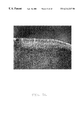
- FIG. 1 is a photomicrograph of a prepared section of a metal cutting insert composed of SD-5 material coated with wear-resistant MT-milling (moderate temperature milling and turning) coating by the method of the present invention
- FIGS. 2 a - 2 c and 3 a - 3 c are photomicrographs showing the condition of an edge surface of each of three metal cutting inserts, composed of SD-5 material and coated with an MT-milling coating by the method of the invention, after 10 and 18 milling passes, respectively;
- FIGS. 4 a - 4 c and 5 a - 5 c are photomicrographs showing the condition of an edge surface of each of three uncoated metal cutting inserts, composed of SD-5 material, after 10 and 18 milling passes, respectively;
- FIGS. 6 a - 6 c are photomicrographs showing the condition of an edge surface of three metal cutting inserts, composed of T-14 material and coated with an MT-milling coating by the method of the invention, after 4 milling passes;
- FIGS. 7 a - 7 c are photomicrographs showing the condition of an edge surface of three metal cutting inserts composed of T-14 material, each insert both unetched and uncoated, after 4 milling passes;
- FIG. 8 is a photomicrograph of a metal cutting insert composed of H-91 material and coated with an MT-milling coating by the method of the present invention
- FIGS. 9 is a photomicrograph showing the condition of a metal cutting insert, composed of H-91 material and coated with an MT-milling coating by the method of the invention, after one milling pass;
- FIG. 10 is a photomicrograph showing the condition of a metal cutting insert, composed of H-91 material and coated with an MT-milling coating of TiN/TiCN/TiN layers totaling approximately 5 microns (applied by CVD), after one milling pass; and
- FIGS. 11 a - 11 d are photomicrographs of a prepared section of a heavy metal part containing tungsten metal particles (about 90 weight percent of the part's total weight) suspended in an iron/nickel binder (about 10 weight percent of the part's total weight) that was etched and coated with an MT-milling coating by the method of the present invention.
- An aspect of the present invention is directed to a method for applying a coating, preferably a wear-resistant coating, to a composite material substrate.
- the composite material substrate includes a phase of a hard constituent and also includes a binder phase that is predominantly one or more of cobalt, nickel, and iron.
- the present inventors have discovered that the method of the invention enhances the adherence of the coating to the composite material substrate and inhibits delamination of the coating.
- the present invention also is directed to etched and etched/coated substrates prepared by the method of the present invention.
- the present method improves adhesion between composite material substrates and wear-resistant coatings by allowing the coatings to infiltrate the surface of the substrate.
- a portion of the binder phase of a surface region of the composite material substrate is removed by a novel etching procedure, preferably to a depth in the range of about 3 to about 15 microns (inclusive), while leaving the hard constituent particles in the surface region substantially intact.
- Wear-resistant coatings applied to composite material substrates that have been etched by the present method infiltrate the voids in the surface region created by removal of the binder phase. The infiltration of the coating is believed to increase the adhesive strength between the coating and the composite material substrate.
- the enhanced adhesion between coatings and composite material substrates achieved by the present method reduces differences in thermal expansion between the substrates and coatings, improves the coatings' resistance to deformation, increases coating wear resistance, and reduces the occurrence of thermal cracking.
- composite material refers to a material, in any form, that includes at least particles of a phase of a hard constituent material and a phase of a binder material that binds together the hard constituent particles.
- the composite material may be, for example, cemented carbides and cermets.
- the binder material of the present composite material may include one or a combination of more than one of cobalt, nickel, copper, and iron.
- the binder material may include other elements and compounds as are known in the art. Such other elements include, for example, those within Group VIII of the periodic table (elements having atomic numbers 26-28, 44-46, and 76-78), tungsten, zinc, and rhenium.
- the particles of the hard constituent may be, for example, particles composed of:
- carbide materials selected from tungsten carbide (WC), titanium carbide (TiC), tantalum carbide (TaC), niobium carbide (NbC), vanadium carbide (VC), chromium carbide (Cr 3 C 2 ), molybdenum carbide (MoC), and iron carbide (FeC);
- one or more carbonitrides and/or nitrides of one or more of the refractory metals including carbonitrides of one or more of W, Ti, Ta, Nb, V, Cr, Mo, and Fe;
- tungsten one or more of tungsten, molybdenum-based materials, and tungsten-based materials.
- refractory metals refers to metals having an extremely high melting point, for example, W, Mo, Ta, Nb, Cr, V, Re, Ti , Pt, and Zr.
- the method of the present invention also may be used to enhance the adhesion of wear-resistant and other types of coatings to other types of materials, including, for example, heavy metals, sialons, Si 3 N 4 , and composite ceramics, that have a phase that may be etched by the present method.
- materials including, for example, heavy metals, sialons, Si 3 N 4 , and composite ceramics, that have a phase that may be etched by the present method.
- the identities of such other materials may be readily determined by those having ordinary skill in the substrate coating arts.
- the following examples are directed to the application of wear-resistant coatings to composite material and other substrates, it will be understood that the present method also may be used to better adhere other types of coatings to such substrates.
- Such other coatings include coatings that impart desirable properties to the substrate surface, such as, for example, coatings that enhance the substrate's resistance to corrosion, including oxidation, or that provide a particular surface appearance to the substrate.
- coatings that impart desirable properties to the substrate surface such as, for example, coatings that enhance the substrate's resistance to corrosion, including oxidation, or that provide a particular surface appearance to the substrate.
- the identities of other coatings that may be applied using the method of the present invention will be readily apparent to those having ordinary skill in the substrate coating arts once apprised of the invention.
- the method generally includes at least the following steps:
- the etchant gas may be selected from, for example, gaseous hydrogen chloride, gaseous H 2 F 2 , or the gaseous form of any of the Group VIIA elements.
- suitable etchant gases will be apparent to those of ordinary skill in the art or may be determined by such persons without undue experimentation, and it will be understood that the identity of such suitable alternative etchant gases will depend on the particular composition of the material that is to be etched.
- the gaseous mixture is applied to the surface of the material to be etched under conditions and for a time suitable to remove the desired amount of binder phase from the material. Such conditions and times may be readily ascertained, without significant experimentation, by those having ordinary skill in the substrate coating arts.
- inert gas such as, for example, nitrogen, argon, or helium gas.
- the method of the invention is disclosed above as being carried out in a chamber of a chemical vapor deposition (CVD) furnace, it will be understood that the etching step may be carried out in any chamber that is sealed from the environment and into which a flow of the gases may be introduced.
- An advantage of carrying out the process in a CVD furnace is that the etching, purging, and coating steps may be carried out sequentially in the furnace chamber without the need to move the composite materials from one chamber to another during the process.
- the method of the invention may be programmed as a complete cycle in the CVD furnace and accomplished in one run.
- This feature of the invention provides a distinct advantage over procedures wherein a liquid solution etchant is used to remove binder phase material because such liquid solutions cannot be introduced into the same chamber employed to coat the substrate by a CVD or PVD process. Also, it has been found that the substrate may be kept cleaner and the depth of etching may be better controlled when using a gaseous etchant as opposed to a liquid etchant.
- the step of etching binder phase from the composite material substrate preferably should remove binder material to a depth of about 3 to about 15 microns and more preferably about 4 to about 6 microns, into the substrate surface. Too shallow an etching depth does not provide a significant enhancement in coating adhesion. Too great an etching depth weakens the surface of the substrate. Etching time may be varied to account for differences in the susceptibility of the particular binder phase to be removed by the etchant gases. Those having ordinary skill in the substrate coating arts may readily determine the etching time necessary to provide a desired depth of etching for a particular substrate. The substrate temperature at which the etching step should be carried out to remove the desired amount of binder material also will depend upon the character of the binder, but may be readily determined.
- Eta phase is a hard and brittle carbon-deficient phase that may easily fracture and may be produced when etching substrates that include tungsten, carbon, and cobalt.
- the presence of eta phase significantly degrades the properties of composite material substrates used in material removal (i.e., cutting, drilling, threading, boring, etc.) applications and, therefore, the generation of eta phase preferably should be avoided during the etching and coating of composite material substrates and other substrates by appropriately adjusting the etching and coating conditions.
- composite material substrates having cobalt binder should be etched at lower substrate temperatures in order to inhibit the formation of eta phase on the surface of the substrate.
- the inventors also have determined that if hydrogen gas is present during an etching step employing a gaseous etchant, the hydrogen may combine with any carbon present as WC and any cobalt within the substrate material and will thereby make the WC deficient in carbon, resulting in formation of an eta phase.
- One possible reaction representative of formation of an eta phase is as follows:
- the eta phase does not convert to CoCl 2 , as is required for the precursor elements of the eta phase to leave the substrate surface as a gas.
- the inventors have concluded that formation of eta phase is significantly inhibited when using nitrogen or certain other gases in substitution for hydrogen gas used in conjunction with etchant gas during the etching step.
- a representation of a possible reaction occurring during etching of a cobalt-containing composite material by a hydrogen chloride etchant gas, and wherein the etchant gas is not applied to the material in combination with hydrogen gas, is believed to be as follows:
- the CoCl 2 is a gaseous product that is swept from the coating furnace during the purging step.
- the inventors have discovered that the step of etching a substrate including tungsten, carbon, and a binder phase including cobalt will not be satisfactorily accomplished if the gaseous etchant mixture includes hydrogen gas.
- the gaseous etchant mixture includes hydrogen gas.
- cobalt residue remains in the voids etched between the tungsten carbide particles and the undesirable eta phase may form, significantly reducing substrate toughness.
- nitrogen gas may be advantageously substituted for hydrogen gas to prevent formation of eta phase.
- gases that may be substituted for hydrogen gas in the gaseous mixture used in the substrate etching step include those selected from one or more of nitrogen gas and other gases that do not react with the substrate or removed binder and that do not change the oxidation state of the substrate.
- gases are believed to include, for example, helium, argon, and neon gases.
- the etchant gas that may be used in the etching step of the method of the present invention may be any gas that will suitably remove the desired depth of binder phase in a surface region of the composite material substrate that is being etched.
- etchant gases include, for example, HCl gas, H 2 F 2 gas, and the gaseous form of any of the Group VIIA elements in the periodic table of the elements.
- the purging step occurring subsequent to the etching step is necessary to remove any products of the etching reaction and any etchant remaining in the chamber, and to reduce any explosion hazard.
- Any gas or combination of gases that will suitably remove the reactant products and remaining etchant gases and that will not react with the binder or hard particle constituents of the composite material may be used as the purging gas.
- Suitable purging gases include, for example, one or more of nitrogen, helium, and argon gases.
- the substrate may then be coated with a wear-resistant or other coating material by any conventional composite substrate coating process.
- a wear-resistant or other coating material include, for example, CVD, PVD, plasma arc, and super lattice processes.
- Still other composite material coating procedures will be readily apparent to those of ordinary skill in the substrate coating arts. All such other suitable coating processes may be used in the present method subsequent to the gas etching procedure.
- Any coating process used to deposit wear-resistant material on a composite material substrate etched by the procedure of the present method is carried out under conditions by which the wear-resistant material may at least partially infiltrate the voids in the composite material created by removal of the binder material.
- One of ordinary skill may readily determine such conditions without undue experimentation.
- the present invention also is directed to a method for removing binder material from a region of a composite material, and the inventive method need not include the subsequent coating step.
- a composite substrate having a roughened surface may be produced by such a method.
- Roughened composite substrates may be used in a variety of known applications, including, for example, ball point pen balls, wherein a roughened surface provides enhanced traction.
- substrates may be etched by the present method and then coated at some later time and/or at a different facility, rather than in a single procedure in which the etching and coating steps are combined.
- a coating that may be applied in a procedure removed in time from the etching procedure and/or at another facility is a diamond coating.
- a Bernex 250 CVD coating furnace was prepared by introducing into the coating chamber of the furnace a 10 l/min (liters/minute) flow of hydrogen gas to establish a 200 mbar hydrogen gas pressure within the chamber. The chamber was then heated to 850° C.
- a cemented carbide substrate composed of H-91 grade material available from Stellram, LaVergne, Tennessee, was placed in the prepared furnace chamber and the chamber atmosphere was heated to 850°.
- H-91 grade material is composed of 88.5 weight percent tungsten carbide, 11.0 weight percent cobalt, and 0.5 weight percent of a mixture of TiC, TaC, and NbC. The material exhibits a hardness of 89.7 HRA, 14.40 g/cc density, and a transverse rupture strength of approximately 389,000 psi.
- the flow of hydrogen gas was then stopped, and a concurrent flow of 20 l/min nitrogen gas and 1 l/min hydrogen chloride gas was introduced into the chamber to provide a chamber pressure of 800 mbar.
- Binder was etched to a depth of approximately 5 microns into the substrate's surface by the running the concurrent N 2 /HCl gas flow into the chamber for 25 minutes, and then discontinuing the flow of HCl gas. While maintaining the chamber atmosphere at 850° C., the chamber was then purged for 15 minutes by continuing the 20 l/min flow of N 2 gas while establishing a 60 mbar chamber pressure.
- MT-milling coating is a multi-layer insert coating consisting of two TiN layers of approximately 1 micron with a TiCN layer of approximately 3 microns disposed between the two TiN layers.
- the MT-milling coating was deposited on the substrate by introducing into the furnace chamber flows of gases that will produce coatings of TiN, TiCN, and then TiN, in that order, as follows.
- the chamber atmosphere was heated to 920° C. and the chamber pressure was reset to 160 mbar. After that pressure was established, a first TiN layer was provided on the substrate by initiating a 9 l/min nitrogen gas flow, increasing the hydrogen gas flow to 14 l/min, and initiating a 2.1 ml/min flow of TiCl 4 gas. The concurrent flows of the three gases were allowed to proceed for 60 minutes while the chamber pressure was maintained at approximately 160 millibars. During the 60-minute period, the furnace temperature was lowered 5-10° C. every fifteen minutes so as to be at approximately 895° C. at the end of the period.
- the interposed TiCN coating was produced by lowering the nitrogen gas flow to 8 l/min, and then resetting chamber pressure to 60 mbar. The TiCl 4 gas flow was then raised to 2.4 ml/min. Once all flows were constant, a flow of CH 3 CN gas generated by vaporizing a 0.3-0.4 ml/min flow of liquid CH 3 CN flow was initiated. The concurrent gas flows were continued for 2 hours, during the first hour of which the furnace temperature was reduced to 870° C. At the end of the 2-hour period, the flows of CH 3 CN and TiCl 4 gases were discontinued.
- the furnace was then purged by shutting off the TiCl 4 gas flow, resetting chamber pressure to 600 mbar, raising hydrogen gas flow to 12 l/min, and lowering nitrogen gas flow to 3.5 l/min.
- the reset gas flows were continued for fifteen minutes.
- the furnace was then subjected to a cool down procedure.
- the MT-milling coating infiltrated at least a portion of the voids etched in the substrate's surface.
- the Bemex 250 CVD furnace used in Example 1 was prepared using the procedure described in that example.
- SD-5 material is a cermet grade material available from Stellram, LaVergne, Tenn., and is composed of TiCN and Mo 2 C particles in a Co/Ni binder.
- SD-5 material has the approximate elemental composition 45.2 Ti, 22.6 Mo, 10.9 C, 2.3 N, 19.0 Ni, and exhibits the following approximate mechanical properties: 91.8 HRA hardness, 6.30 g/cc density, and a transverse rupture strength of 300,000 psi.
- the Co/Ni binder was then etched to a depth of 5 microns from the substrate's surface using concurrent flows of hydrogen chloride and nitrogen gases at the flow rates, pressure, and reaction time used in Example 1 above.
- the furnace chamber was then purged using a 20 l/min flow of N 2 gas for 15 minutes at a chamber pressure of 60 millibars.
- the etched composite was then coated with an MT-milling coating using the procedure of Example 1.
- the MT-milling coating infiltrated the etched voids to a depth of 5 microns ⁇ approximately 1 micron, and with approximately 1 micron of the coating disposed above the substrate's surface.
- Three Stellram cutting inserts of type SEKN-42-AF4B composed of SD-5 material (as described in Example 2) were first etched and then coated with the MT-milling coating by the following procedure.
- FIG. 1 is a photomicrograph (2040X) of a prepared cross-section through the surface of one of the etched and coated SD-5 inserts. The photomicrograph shows the infiltration of the MT-milling coating into the voids etched in the insert surface. The infiltration of the coating into the voids increased the adherence of the coating to the insert and improved the thermal shock resistance of the coating.
- the SD-5 inserts were pulled and inspected after every two 16.5 inch milling passes. After the initial two passes, one uncoated SD-5 insert had one thermal crack started and the five remaining SD-5 inserts did not exhibit thermal cracks. After ten passes, all three unetched/uncoated SD-5 inserts exhibited one or more thermal cracks while only one etched and coated SD-5 insert exhibited a single thermal crack. Milling testing was concluded after 18 passes, at which point each unetched/uncoated insert exhibited 2-4 thermal cracks on their used edges, while only one thermal crack existed in one etched and coated insert.
- the conditions of an edge surface of each of the three etched/coated SD-5 inserts after 10 and 18 passes are shown in FIGS. 2 a-c and 3 a-c , respectively.
- the used edge conditions of the three unetched/uncoated SD-5 inserts after 10 and 18 passes are shown in FIGS. 4 a -c and 5 a-c , respectively.
- T-14 material is a milling grade material available from Stellram (LaVergne, Tenn.) having a nominal composition composed of 70 weight percent tungsten carbide and 20 weight percent of a combination of tantalum carbide, niobium, and titanium carbide. Particles of the foregoing material are bound together by a cobalt binder that is 10 weight percent of the total weight of the material.
- T-14 material typically exhibits a hardness of 91.20 HRA, 12.43 g/cc density, and an average transverse rupture strength of 296,000 psi.
- thermal crack breakout is the point at which two or more thermal cracks connect and just before the insert surface fractures. Photomicrographs showing the condition of the depth-of-cut region of the three etched and coated T-14 inserts and the three unetched and uncoated T-14 inserts are shown in FIGS. 6 a-c and 7 a-c , respectively.
- Stellram SEKN-42-AF4B type cutting inserts composed of H-91 grade material were obtained.
- Half of the H-91 inserts were coated with MT-mill coating in a Bernex 325 furnace using an automated procedure substantially similar to the above-described MT-milling coating procedure so as to provide a layered coating on the inserts composed of approximately 1 micron TiN, approximately 3 microns TiCN, and then 1 micron TiN, all such thicknesses being approximate.
- the remaining H-91 grade inserts were etched in a Bemex 250 CVD furnace using the procedure of Example 1 and the etched inserts were then MT-milling coated in the furnace by the procedure described in Example 3.
- This example 5 compared inserts composed of identical base materials and identical coatings, with the only significant difference being that the test samples of one set were first etched by the present method and the MT-milling coating had infiltrated the resulting interstices in the inserts' surfaces.
- the etched and infiltrated inserts exhibited significantly increased resistance to thermal cracking relative to the unetched coated inserts.
- a heavy metal part containing 90 weight percent tungsten metal particles suspended in 10 weight percent of an iron/nickel binder was etched and coated with an MT-milling coating using the procedures of the invention as generally described in the foregoing examples involving insert composed of SD-5 material.
- 21X photomicrographs of sections of the etched and coated metal part taken through the coated surface are shown in FIGS. 11 a - 11 d .
Abstract
Description
Claims (19)
Priority Applications (3)
| Application Number | Priority Date | Filing Date | Title |
|---|---|---|---|
| US09/095,398 US6214247B1 (en) | 1998-06-10 | 1998-06-10 | Substrate treatment method |
| US09/627,801 US6929851B1 (en) | 1998-06-10 | 2000-07-28 | Coated substrate |
| US09/627,931 US6358428B1 (en) | 1998-06-10 | 2000-07-28 | Method of etching |
Applications Claiming Priority (1)
| Application Number | Priority Date | Filing Date | Title |
|---|---|---|---|
| US09/095,398 US6214247B1 (en) | 1998-06-10 | 1998-06-10 | Substrate treatment method |
Related Child Applications (2)
| Application Number | Title | Priority Date | Filing Date |
|---|---|---|---|
| US09/627,801 Division US6929851B1 (en) | 1998-06-10 | 2000-07-28 | Coated substrate |
| US09/627,931 Division US6358428B1 (en) | 1998-06-10 | 2000-07-28 | Method of etching |
Publications (1)
| Publication Number | Publication Date |
|---|---|
| US6214247B1 true US6214247B1 (en) | 2001-04-10 |
Family
ID=22251805
Family Applications (3)
| Application Number | Title | Priority Date | Filing Date |
|---|---|---|---|
| US09/095,398 Expired - Lifetime US6214247B1 (en) | 1998-06-10 | 1998-06-10 | Substrate treatment method |
| US09/627,801 Expired - Fee Related US6929851B1 (en) | 1998-06-10 | 2000-07-28 | Coated substrate |
| US09/627,931 Expired - Lifetime US6358428B1 (en) | 1998-06-10 | 2000-07-28 | Method of etching |
Family Applications After (2)
| Application Number | Title | Priority Date | Filing Date |
|---|---|---|---|
| US09/627,801 Expired - Fee Related US6929851B1 (en) | 1998-06-10 | 2000-07-28 | Coated substrate |
| US09/627,931 Expired - Lifetime US6358428B1 (en) | 1998-06-10 | 2000-07-28 | Method of etching |
Country Status (1)
| Country | Link |
|---|---|
| US (3) | US6214247B1 (en) |
Cited By (26)
| Publication number | Priority date | Publication date | Assignee | Title |
|---|---|---|---|---|
| US6666288B2 (en) * | 2000-12-22 | 2003-12-23 | Seco Tools Ab | Coated cutting tool insert with iron-nickel based binder phase |
| US20050112901A1 (en) * | 2003-09-30 | 2005-05-26 | Bing Ji | Removal of transition metal ternary and/or quaternary barrier materials from a substrate |
| US20050191482A1 (en) * | 2003-01-13 | 2005-09-01 | Liu Shaiw-Rong S. | High-performance hardmetal materials |
| US20050233133A1 (en) * | 2000-05-19 | 2005-10-20 | Tdk Corporation | Functional film |
| US20070034048A1 (en) * | 2003-01-13 | 2007-02-15 | Liu Shaiw-Rong S | Hardmetal materials for high-temperature applications |
| US20070054146A1 (en) * | 2003-04-28 | 2007-03-08 | Tatsuhiko Aizawa | High-speed machining tool |
| US20070119276A1 (en) * | 2005-03-15 | 2007-05-31 | Liu Shaiw-Rong S | High-Performance Friction Stir Welding Tools |
| US20080057327A1 (en) * | 2004-05-19 | 2008-03-06 | Tdy Industries, Inc. | Al2O3 Ceramic Tool with Diffusion Bonding Enhanced Layer |
| US20080196318A1 (en) * | 2007-02-19 | 2008-08-21 | Tdy Industries, Inc. | Carbide Cutting Insert |
| US20080257107A1 (en) * | 2003-01-13 | 2008-10-23 | Genius Metal, Inc. | Compositions of Hardmetal Materials with Novel Binders |
| WO2009046777A1 (en) * | 2007-10-02 | 2009-04-16 | H.C. Starck Gmbh | Tool |
| US20100044115A1 (en) * | 2008-08-22 | 2010-02-25 | Tdy Industries, Inc. | Earth-boring bit parts including hybrid cemented carbides and methods of making the same |
| US20110052931A1 (en) * | 2009-08-25 | 2011-03-03 | Tdy Industries, Inc. | Coated Cutting Tools Having a Platinum Group Metal Concentration Gradient and Related Processes |
| US8221517B2 (en) | 2008-06-02 | 2012-07-17 | TDY Industries, LLC | Cemented carbide—metallic alloy composites |
| US8225886B2 (en) | 2008-08-22 | 2012-07-24 | TDY Industries, LLC | Earth-boring bits and other parts including cemented carbide |
| US8312941B2 (en) | 2006-04-27 | 2012-11-20 | TDY Industries, LLC | Modular fixed cutter earth-boring bits, modular fixed cutter earth-boring bit bodies, and related methods |
| RU2496608C1 (en) * | 2012-03-15 | 2013-10-27 | Общество с ограниченной ответственностью "Завод-ВТУЗ "База знаний" | Invention relates to application of antiwear film on cutting tool surface |
| US8637127B2 (en) | 2005-06-27 | 2014-01-28 | Kennametal Inc. | Composite article with coolant channels and tool fabrication method |
| US8697258B2 (en) | 2006-10-25 | 2014-04-15 | Kennametal Inc. | Articles having improved resistance to thermal cracking |
| US8790439B2 (en) | 2008-06-02 | 2014-07-29 | Kennametal Inc. | Composite sintered powder metal articles |
| US8800848B2 (en) | 2011-08-31 | 2014-08-12 | Kennametal Inc. | Methods of forming wear resistant layers on metallic surfaces |
| US9016406B2 (en) | 2011-09-22 | 2015-04-28 | Kennametal Inc. | Cutting inserts for earth-boring bits |
| JP2015178172A (en) * | 2014-02-26 | 2015-10-08 | 三菱マテリアル株式会社 | Cutting tool made of surface coating carbonitride titanium based cermet excellent in chipping resistance |
| US10570501B2 (en) | 2017-05-31 | 2020-02-25 | Kennametal Inc. | Multilayer nitride hard coatings |
| AT522605A1 (en) * | 2019-05-23 | 2020-12-15 | Boehlerit Gmbh & Co Kg | Carbide insert |
| WO2024050571A1 (en) | 2022-09-05 | 2024-03-14 | Carboncompetence Gmbh | Method for preparing a substrate coated with an intermediate layer and a diamond layer |
Families Citing this family (15)
| Publication number | Priority date | Publication date | Assignee | Title |
|---|---|---|---|---|
| MXPA04004490A (en) | 2001-11-13 | 2005-05-16 | Acme United Corp | Coating for stationery cutting implements. |
| US7913402B2 (en) | 2001-11-13 | 2011-03-29 | Acme United Corporation | Coating for cutting implements |
| US7934319B2 (en) | 2002-10-28 | 2011-05-03 | Acme United Corporation | Pencil-sharpening device |
| US7429152B2 (en) * | 2003-06-17 | 2008-09-30 | Kennametal Inc. | Uncoated cutting tool using brazed-in superhard blank |
| US7592077B2 (en) * | 2003-06-17 | 2009-09-22 | Kennametal Inc. | Coated cutting tool with brazed-in superhard blank |
| WO2006126520A1 (en) * | 2005-05-24 | 2006-11-30 | Matsushita Electric Industrial Co., Ltd. | Dry etching method, method for forming fine structure, mold and method for producing same |
| US7754350B2 (en) * | 2006-05-02 | 2010-07-13 | United Technologies Corporation | Wear-resistant coating |
| US8530050B2 (en) * | 2007-05-22 | 2013-09-10 | United Technologies Corporation | Wear resistant coating |
| CN102181677B (en) * | 2011-04-01 | 2013-03-13 | 赣县世瑞新材料有限公司 | Hard alloy and preparation method thereof |
| US9725794B2 (en) * | 2014-12-17 | 2017-08-08 | Kennametal Inc. | Cemented carbide articles and applications thereof |
| US11639315B2 (en) | 2017-09-07 | 2023-05-02 | General Electric Company | Bond coatings having a molten silicon-phase contained between refractory layers |
| US11401217B2 (en) | 2017-09-07 | 2022-08-02 | General Electric Company | Bond coatings having a silicon-phase contained within a refractory phase |
| US11773734B2 (en) | 2017-09-07 | 2023-10-03 | General Electric Company | Liquid bond coatings for barrier coatings |
| CN109659535B (en) * | 2018-12-18 | 2021-07-16 | 中科廊坊过程工程研究院 | Molybdenum carbide/carbon composite material and preparation method and application thereof |
| CN111534733A (en) * | 2020-03-25 | 2020-08-14 | 成都美奢锐新材料有限公司 | Wear-resistant coating material and preparation method thereof, and coating spraying method and repairing method |
Citations (12)
| Publication number | Priority date | Publication date | Assignee | Title |
|---|---|---|---|---|
| US4282289A (en) | 1980-04-16 | 1981-08-04 | Sandvik Aktiebolag | Method of preparing coated cemented carbide product and resulting product |
| WO1992020841A1 (en) | 1991-05-15 | 1992-11-26 | Sandvik Ab | Etching process |
| US5236740A (en) | 1991-04-26 | 1993-08-17 | National Center For Manufacturing Sciences | Methods for coating adherent diamond films on cemented tungsten carbide substrates |
| US5336292A (en) | 1991-06-17 | 1994-08-09 | Sandvik Ab | Titanium-based carbonitride alloy with wear resistant surface layer |
| US5368938A (en) * | 1984-09-24 | 1994-11-29 | Air Products And Chemicals, Inc. | Oxidation resistant carbon and method for making same |
| US5415674A (en) | 1993-03-26 | 1995-05-16 | Schwartzkopf Technologies Corporation | Cemented carbide substrate having a diamond layer of high adhesive strength |
| US5419927A (en) | 1988-09-26 | 1995-05-30 | Chromalloy Gas Turbine Corporation | Process for coating fiber reinforced ceramic composites |
| US5560839A (en) | 1994-06-27 | 1996-10-01 | Valenite Inc. | Methods of preparing cemented metal carbide substrates for deposition of adherent diamond coatings and products made therefrom |
| US5571616A (en) | 1995-05-16 | 1996-11-05 | Crystallume | Ultrasmooth adherent diamond film coated article and method for making same |
| US5700518A (en) | 1996-04-26 | 1997-12-23 | Korea Institute Of Science And Technology | Fabrication method for diamond-coated cemented carbide cutting tool |
| US5891522A (en) | 1995-05-24 | 1999-04-06 | Saint-Gobain Industrial Ceramics, Inc. | Composite article with adherent CVD diamond coating and method of making |
| US5900288A (en) | 1994-01-03 | 1999-05-04 | Xerox Corporation | Method for improving substrate adhesion in fluoropolymer deposition processes |
Family Cites Families (12)
| Publication number | Priority date | Publication date | Assignee | Title |
|---|---|---|---|---|
| US4399168A (en) * | 1980-01-21 | 1983-08-16 | Santrade Ltd. | Method of preparing coated cemented carbide product |
| US5204167A (en) * | 1989-02-23 | 1993-04-20 | Toshiba Tungaloy Co., Ltd. | Diamond-coated sintered body excellent in adhesion and process for preparing the same |
| SE9002136D0 (en) * | 1990-06-15 | 1990-06-15 | Sandvik Ab | CEMENT CARBIDE BODY FOR ROCK DRILLING, MINERAL CUTTING AND HIGHWAY ENGINEERING |
| WO1993002022A1 (en) * | 1991-07-22 | 1993-02-04 | Sumitomo Electric Industries, Ltd. | Diamond-clad hard material and method of making said material |
| DE69319531T2 (en) * | 1992-10-12 | 1999-04-15 | Sumitomo Electric Industries | Ultra thin film laminate |
| US5372873A (en) * | 1992-10-22 | 1994-12-13 | Mitsubishi Materials Corporation | Multilayer coated hard alloy cutting tool |
| US5374471A (en) * | 1992-11-27 | 1994-12-20 | Mitsubishi Materials Corporation | Multilayer coated hard alloy cutting tool |
| SE505425C2 (en) * | 1992-12-18 | 1997-08-25 | Sandvik Ab | Carbide metal with binder phase enriched surface zone |
| SE9300376L (en) * | 1993-02-05 | 1994-08-06 | Sandvik Ab | Carbide metal with binder phase-oriented surface zone and improved egg toughness behavior |
| US5494635A (en) * | 1993-05-20 | 1996-02-27 | Valenite Inc. | Stratified enriched zones formed by the gas phase carburization and the slow cooling of cemented carbide substrates, and methods of manufacture |
| WO1995005497A1 (en) * | 1993-08-16 | 1995-02-23 | Sumitomo Electric Industries, Ltd. | Cemented carbide alloy for cutting tool and coated cemented carbide alloy |
| US5674620A (en) * | 1994-08-11 | 1997-10-07 | Saint-Gobain/Norton Industrial Ceramics Corporation | Diamond-coated composite cutting tool and method of making |
-
1998
- 1998-06-10 US US09/095,398 patent/US6214247B1/en not_active Expired - Lifetime
-
2000
- 2000-07-28 US US09/627,801 patent/US6929851B1/en not_active Expired - Fee Related
- 2000-07-28 US US09/627,931 patent/US6358428B1/en not_active Expired - Lifetime
Patent Citations (15)
| Publication number | Priority date | Publication date | Assignee | Title |
|---|---|---|---|---|
| US4282289A (en) | 1980-04-16 | 1981-08-04 | Sandvik Aktiebolag | Method of preparing coated cemented carbide product and resulting product |
| US5368938A (en) * | 1984-09-24 | 1994-11-29 | Air Products And Chemicals, Inc. | Oxidation resistant carbon and method for making same |
| US5419927A (en) | 1988-09-26 | 1995-05-30 | Chromalloy Gas Turbine Corporation | Process for coating fiber reinforced ceramic composites |
| US5236740A (en) | 1991-04-26 | 1993-08-17 | National Center For Manufacturing Sciences | Methods for coating adherent diamond films on cemented tungsten carbide substrates |
| US5567526A (en) | 1991-04-26 | 1996-10-22 | National Center For Manufacturing Sciences | Cemented tungsten carbide substrates having adherent diamond films coated thereon |
| WO1992020841A1 (en) | 1991-05-15 | 1992-11-26 | Sandvik Ab | Etching process |
| US5380408A (en) | 1991-05-15 | 1995-01-10 | Sandvik Ab | Etching process |
| US5336292A (en) | 1991-06-17 | 1994-08-09 | Sandvik Ab | Titanium-based carbonitride alloy with wear resistant surface layer |
| US5415674A (en) | 1993-03-26 | 1995-05-16 | Schwartzkopf Technologies Corporation | Cemented carbide substrate having a diamond layer of high adhesive strength |
| US5900288A (en) | 1994-01-03 | 1999-05-04 | Xerox Corporation | Method for improving substrate adhesion in fluoropolymer deposition processes |
| US5560839A (en) | 1994-06-27 | 1996-10-01 | Valenite Inc. | Methods of preparing cemented metal carbide substrates for deposition of adherent diamond coatings and products made therefrom |
| US5713133A (en) | 1994-06-27 | 1998-02-03 | Valenite Inc. | Methods of preparing cemented metal carbide substrates for deposition of adherent diamond coatings and products made therefrom |
| US5571616A (en) | 1995-05-16 | 1996-11-05 | Crystallume | Ultrasmooth adherent diamond film coated article and method for making same |
| US5891522A (en) | 1995-05-24 | 1999-04-06 | Saint-Gobain Industrial Ceramics, Inc. | Composite article with adherent CVD diamond coating and method of making |
| US5700518A (en) | 1996-04-26 | 1997-12-23 | Korea Institute Of Science And Technology | Fabrication method for diamond-coated cemented carbide cutting tool |
Cited By (45)
| Publication number | Priority date | Publication date | Assignee | Title |
|---|---|---|---|---|
| US7452435B2 (en) * | 2000-05-19 | 2008-11-18 | Tdk Corporation | Functional film |
| US20050233133A1 (en) * | 2000-05-19 | 2005-10-20 | Tdk Corporation | Functional film |
| US6666288B2 (en) * | 2000-12-22 | 2003-12-23 | Seco Tools Ab | Coated cutting tool insert with iron-nickel based binder phase |
| US20050191482A1 (en) * | 2003-01-13 | 2005-09-01 | Liu Shaiw-Rong S. | High-performance hardmetal materials |
| US20070034048A1 (en) * | 2003-01-13 | 2007-02-15 | Liu Shaiw-Rong S | Hardmetal materials for high-temperature applications |
| US20100180514A1 (en) * | 2003-01-13 | 2010-07-22 | Genius Metal, Inc. | High-Performance Hardmetal Materials |
| US7645315B2 (en) | 2003-01-13 | 2010-01-12 | Worldwide Strategy Holdings Limited | High-performance hardmetal materials |
| US20080257107A1 (en) * | 2003-01-13 | 2008-10-23 | Genius Metal, Inc. | Compositions of Hardmetal Materials with Novel Binders |
| US20070054146A1 (en) * | 2003-04-28 | 2007-03-08 | Tatsuhiko Aizawa | High-speed machining tool |
| US20050112901A1 (en) * | 2003-09-30 | 2005-05-26 | Bing Ji | Removal of transition metal ternary and/or quaternary barrier materials from a substrate |
| US7371688B2 (en) * | 2003-09-30 | 2008-05-13 | Air Products And Chemicals, Inc. | Removal of transition metal ternary and/or quaternary barrier materials from a substrate |
| US7968147B2 (en) | 2004-05-19 | 2011-06-28 | Tdy Industries, Inc. | Method of forming a diffusion bonding enhanced layer on Al2O3 ceramic tools |
| US20100227160A1 (en) * | 2004-05-19 | 2010-09-09 | Tdy Industries, Inc. | Al203 CERAMIC TOOLS WITH DIFFUSION BONDING ENHANCED LAYER |
| US20090186154A1 (en) * | 2004-05-19 | 2009-07-23 | Tdy Industries, Inc. | Method of forming a diffusion bonding enhanced layer on al2o3 ceramic tools |
| US8147992B2 (en) | 2004-05-19 | 2012-04-03 | TDY Industries, LLC | AL2O3 ceramic tools with diffusion bonding enhanced layer |
| US7914913B2 (en) | 2004-05-19 | 2011-03-29 | Tdy Industries, Inc. | Al2O3 ceramic tool with diffusion bonding enhanced layer |
| US20080057327A1 (en) * | 2004-05-19 | 2008-03-06 | Tdy Industries, Inc. | Al2O3 Ceramic Tool with Diffusion Bonding Enhanced Layer |
| US20070119276A1 (en) * | 2005-03-15 | 2007-05-31 | Liu Shaiw-Rong S | High-Performance Friction Stir Welding Tools |
| US7857188B2 (en) | 2005-03-15 | 2010-12-28 | Worldwide Strategy Holding Limited | High-performance friction stir welding tools |
| US8637127B2 (en) | 2005-06-27 | 2014-01-28 | Kennametal Inc. | Composite article with coolant channels and tool fabrication method |
| US8312941B2 (en) | 2006-04-27 | 2012-11-20 | TDY Industries, LLC | Modular fixed cutter earth-boring bits, modular fixed cutter earth-boring bit bodies, and related methods |
| US8789625B2 (en) | 2006-04-27 | 2014-07-29 | Kennametal Inc. | Modular fixed cutter earth-boring bits, modular fixed cutter earth-boring bit bodies, and related methods |
| US8697258B2 (en) | 2006-10-25 | 2014-04-15 | Kennametal Inc. | Articles having improved resistance to thermal cracking |
| US8512882B2 (en) | 2007-02-19 | 2013-08-20 | TDY Industries, LLC | Carbide cutting insert |
| US20080196318A1 (en) * | 2007-02-19 | 2008-08-21 | Tdy Industries, Inc. | Carbide Cutting Insert |
| US20100239855A1 (en) * | 2007-10-02 | 2010-09-23 | H.C. Starck Gmbh | Tool |
| WO2009046777A1 (en) * | 2007-10-02 | 2009-04-16 | H.C. Starck Gmbh | Tool |
| US8790439B2 (en) | 2008-06-02 | 2014-07-29 | Kennametal Inc. | Composite sintered powder metal articles |
| US8221517B2 (en) | 2008-06-02 | 2012-07-17 | TDY Industries, LLC | Cemented carbide—metallic alloy composites |
| US20100044115A1 (en) * | 2008-08-22 | 2010-02-25 | Tdy Industries, Inc. | Earth-boring bit parts including hybrid cemented carbides and methods of making the same |
| US8322465B2 (en) | 2008-08-22 | 2012-12-04 | TDY Industries, LLC | Earth-boring bit parts including hybrid cemented carbides and methods of making the same |
| US8225886B2 (en) | 2008-08-22 | 2012-07-24 | TDY Industries, LLC | Earth-boring bits and other parts including cemented carbide |
| US8440314B2 (en) | 2009-08-25 | 2013-05-14 | TDY Industries, LLC | Coated cutting tools having a platinum group metal concentration gradient and related processes |
| US20110052931A1 (en) * | 2009-08-25 | 2011-03-03 | Tdy Industries, Inc. | Coated Cutting Tools Having a Platinum Group Metal Concentration Gradient and Related Processes |
| US8800848B2 (en) | 2011-08-31 | 2014-08-12 | Kennametal Inc. | Methods of forming wear resistant layers on metallic surfaces |
| US9016406B2 (en) | 2011-09-22 | 2015-04-28 | Kennametal Inc. | Cutting inserts for earth-boring bits |
| RU2496608C1 (en) * | 2012-03-15 | 2013-10-27 | Общество с ограниченной ответственностью "Завод-ВТУЗ "База знаний" | Invention relates to application of antiwear film on cutting tool surface |
| JP2015178172A (en) * | 2014-02-26 | 2015-10-08 | 三菱マテリアル株式会社 | Cutting tool made of surface coating carbonitride titanium based cermet excellent in chipping resistance |
| EP3112064A4 (en) * | 2014-02-26 | 2017-10-11 | Mitsubishi Materials Corporation | Cutting tool made of surface-coated titanium carbonitride-based cermet having exceptional chipping resistance |
| US10076789B2 (en) | 2014-02-26 | 2018-09-18 | Mitsubishi Materials Corporation | Surface-coated titanium carbonitride-based cermet cutting tool having excellent chipping resistance |
| US10570501B2 (en) | 2017-05-31 | 2020-02-25 | Kennametal Inc. | Multilayer nitride hard coatings |
| US11453063B2 (en) | 2017-05-31 | 2022-09-27 | Kennametal Inc. | Multilayer nitride hard coatings |
| AT522605A1 (en) * | 2019-05-23 | 2020-12-15 | Boehlerit Gmbh & Co Kg | Carbide insert |
| AT522605B1 (en) * | 2019-05-23 | 2021-02-15 | Boehlerit Gmbh & Co Kg | Carbide insert |
| WO2024050571A1 (en) | 2022-09-05 | 2024-03-14 | Carboncompetence Gmbh | Method for preparing a substrate coated with an intermediate layer and a diamond layer |
Also Published As
| Publication number | Publication date |
|---|---|
| US6358428B1 (en) | 2002-03-19 |
| US6929851B1 (en) | 2005-08-16 |
Similar Documents
| Publication | Publication Date | Title |
|---|---|---|
| US6214247B1 (en) | Substrate treatment method | |
| US6827975B2 (en) | Method of coating cutting tools | |
| KR960015546B1 (en) | Diffusion barrier coating material | |
| US4268582A (en) | Boride coated cemented carbide | |
| US5750247A (en) | Coated cutting tool having an outer layer of TiC | |
| US5364209A (en) | CVD and PVD coated cutting tools | |
| US20060286410A1 (en) | Cemented carbide insert for toughness demanding short hole drilling operations | |
| US20100330360A1 (en) | Surface-Coated Member and Cutting Tool | |
| JPH08506620A (en) | Cemented carbide with surface area rich in binder phase and improved edge toughness strength | |
| EP0857095B1 (en) | Anchored oxide coatings on hard metal cutting tools | |
| JPH0615714B2 (en) | Sintered hard metal products | |
| EP1192050B1 (en) | Substrate treatment method | |
| KR930010709B1 (en) | Surface-coated hard member having excellent abrasion resistance | |
| JPH0364469A (en) | Coated sintered hard alloy tool | |
| JP2974285B2 (en) | Manufacturing method of coated carbide tool | |
| JP2660180B2 (en) | Coated carbide tool | |
| JP2648718B2 (en) | Manufacturing method of coated cemented carbide tool | |
| JP2974284B2 (en) | Manufacturing method of coated carbide tool | |
| JPH058103A (en) | Cutting tool member made of surface-coated tungsten carbide base sintered alloy | |
| JPS5935675A (en) | Surface-coated sintered alloy member for cutting tool | |
| JPH0693367A (en) | Coated ultra hard alloy tool |
Legal Events
| Date | Code | Title | Description |
|---|---|---|---|
| AS | Assignment |
Owner name: TELEDYNE INDUSTRIES, INC., CALIFORNIA Free format text: ASSIGNMENT OF ASSIGNORS INTEREST;ASSIGNORS:LEVERENZ, ROY V.;BOST, JOHN;REEL/FRAME:009251/0551 Effective date: 19980427 |
|
| STCF | Information on status: patent grant |
Free format text: PATENTED CASE |
|
| FPAY | Fee payment |
Year of fee payment: 4 |
|
| FPAY | Fee payment |
Year of fee payment: 8 |
|
| FPAY | Fee payment |
Year of fee payment: 12 |
|
| AS | Assignment |
Owner name: TDY INDUSTRIES, LLC, PENNSYLVANIA Free format text: CHANGE OF NAME;ASSIGNOR:TDY INDUSTRIES, INC.;REEL/FRAME:031200/0707 Effective date: 20120102 Owner name: TDY INDUSTRIES, INC., PENNSYLVANIA Free format text: CHANGE OF NAME;ASSIGNOR:TELEDYNE INDUSTRIES, INC.;REEL/FRAME:031200/0274 Effective date: 19991209 |
|
| AS | Assignment |
Owner name: KENNAMETAL INC., PENNSYLVANIA Free format text: ASSIGNMENT OF ASSIGNORS INTEREST;ASSIGNOR:TDY INDUSTRIES, LLC;REEL/FRAME:031640/0510 Effective date: 20131104 |