US6222369B1 - Method and apparatus for determining battery properties from complex impedance/admittance - Google Patents
Method and apparatus for determining battery properties from complex impedance/admittance Download PDFInfo
- Publication number
- US6222369B1 US6222369B1 US09/491,509 US49150900A US6222369B1 US 6222369 B1 US6222369 B1 US 6222369B1 US 49150900 A US49150900 A US 49150900A US 6222369 B1 US6222369 B1 US 6222369B1
- Authority
- US
- United States
- Prior art keywords
- battery
- electrochemical cell
- ability
- elements
- electrical
- Prior art date
- Legal status (The legal status is an assumption and is not a legal conclusion. Google has not performed a legal analysis and makes no representation as to the accuracy of the status listed.)
- Expired - Lifetime
Links
Images


Classifications
-
- G—PHYSICS
- G01—MEASURING; TESTING
- G01R—MEASURING ELECTRIC VARIABLES; MEASURING MAGNETIC VARIABLES
- G01R31/00—Arrangements for testing electric properties; Arrangements for locating electric faults; Arrangements for electrical testing characterised by what is being tested not provided for elsewhere
- G01R31/36—Arrangements for testing, measuring or monitoring the electrical condition of accumulators or electric batteries, e.g. capacity or state of charge [SoC]
- G01R31/389—Measuring internal impedance, internal conductance or related variables
-
- G—PHYSICS
- G01—MEASURING; TESTING
- G01R—MEASURING ELECTRIC VARIABLES; MEASURING MAGNETIC VARIABLES
- G01R31/00—Arrangements for testing electric properties; Arrangements for locating electric faults; Arrangements for electrical testing characterised by what is being tested not provided for elsewhere
- G01R31/36—Arrangements for testing, measuring or monitoring the electrical condition of accumulators or electric batteries, e.g. capacity or state of charge [SoC]
- G01R31/367—Software therefor, e.g. for battery testing using modelling or look-up tables
Definitions
- Small-signal ac measurement techniques have proven useful in determining properties of electrochemical cells and batteries such as cranking power, percent capacity, and state-of-health. These techniques have generally utilized single-frequency measurements of a single quantity, such as conductance (e.g., U.S. Pat. Nos. 5,585,728 and 5,140,269 to Champlin), resistance (e.g., U.S. Pat. No. 3,676,770 to Sharaf et al, U.S. Pat. No. 3,753,094 to Furuishi, U.S. Pat. No. 5,047,722 to Wurst et al), or “impedance” (e.g., U.S. Pat. No.
- Muramatsu discloses one approach to this challenge in U.S. Pat. No. 4,678,998. He measures impedance magnitude at two frequencies. At each frequency he compares the measured magnitude with that of a predetermined experimental relationship between impedance magnitude, remaining capacity, and remaining service life. He reports that such measurements can separately determine the battery's remaining capacity and its remaining service life. Randin discloses a second approach in U.S. Pat. No. 4,743,855. He reportedly determines a battery's state-of-discharge from the argument (i-e., phase angle) of the difference between complex impedances measured at two frequencies. Bounaga discloses still another approach in U.S. Pat. No. 5,650,937.
- Equivalent circuit modeling may assist one in relating complex immittance spectra to electrical, chemical, or physical properties of a battery.
- a complex nonlinear least-squares curve-fitting procedure has been used by electrochemists to relate impedance spectra to nonlinear electrochemical models.
- This complex procedure requires measuring the complete spectral distribution of cell/battery impedance and then making initial estimates of the model's parameters to ensure ultimate convergence.
- An equivalent circuit model is an interconnection of electrical elements introduced to represent terminal characteristics of the battery. In a linear small-signal model, these elements comprise discrete resistances capacitances and inductances.
- Such models have been described by a number of workers including Hampson, et al (N. A. Hampson, et al, “The Impedance of Electrical Storage Cells”, Journal of Applied Electrochemistry, 10, pp.3-11, 1980), Willihnganz and Rohner (E. Willihnganz and Peter Rohner, “Battery Impedance”, Electrical Engineering, 78, No. 9, pp. 922-925, September, 1959), and DeBardelaben (S.
- a device includes a microprocessor or microcontroller and measures real and imaginary parts of complex immittance of a cell or battery at n discrete frequencies, where n is an integer number equal to or greater than 2.
- the device determines cell/battery properties by evaluating components of an equivalent circuit model comprising 2n frequency-independent linear electrical elements. Equating measured real and imaginary parts of complex immittance to theoretical real and imaginary values appropriate to the model at each of the n discrete frequencies defines a set of 2n nonlinear equations in 2n unknowns. By introducing 2n intermediate variables, this daunting problem is made linear and is systematically solved for the values of the components of the model.
- circuit element values may themselves comprise the desired result.
- the circuit elements represent actual processes occurring within the battery. Accordingly, a predetermined relationship between one or more of the elements and an additional electrical, chemical, or physical property of the cell/battery may be invoked to determine the additional property.
- the method and apparatus disclosed herein are efficient, accurate, and easily implemented with a microcontroller or microprocessor.
- the invention is suitable for a variety of diagnostic applications ranging from hand-held battery testers to “smart” battery chargers and battery “fuel gauges” in electric vehicles.
- a lead-acid automotive storage battery is used as an example to teach the method, the invention is equally applicable to both primary and secondary cells and batteries, and to those employed in a variety of other applications and/or employing other chemical systems.
- FIG. 1 a is a spectral plot of measured real part of admittance of an actual 12-volt automotive storage battery.
- FIG. 1 b is a spectral plot of measured imaginary part of admittance of an actual 12-volt automotive storage battery.
- FIG. 2 depicts a general small-signal ac equivalent circuit model of a cell or battery comprising 2n frequency-independent linear elements.
- FIG. 4 a is a plot of the experimental data of FIG. 1 a compared with a theoretical curve calculated from the model of FIG. 3 .
- FIG. 4 b is a plot of the experimental data of FIG. 1 b compared with a theoretical curve calculated from the model of FIG. 3 .
- FIG. 6 a is a plot of the experimental data of FIG. 1 a compared with a theoretical curve calculated from the model of FIG. 5 .
- FIG. 6 b is a plot of the experimental data of FIG. 1 b compared with a theoretical curve calculated from the model of FIG. 5 .
- FIG. 7 is a block diagram of a device for determining battery properties from spot-frequency complex immittance according to the present invention.
- FIG. 8 is a flow chart depicting the control algorithm for the invention embodiment discloses in FIG. 7 .
- the impedance of a cell or battery is a complex quantity.
- spot frequency f k
- the complex impedance can be written in terms of its real and imaginary parts as
- R(f k ) and X(f k ) are, respectively, the resistance and the reactance of the cell/battery at the frequency f k . They physically represent ratios of in-phase voltage amplitude to current amplitude, and quadrature voltage amplitude to current amplitude, respectively, at the frequency f k .
- the admittance of a cell or battery is likewise a complex quantity.
- spot frequency f k
- the real quantities G(f k ) and B(f k ) are, respectively, the conductance and the susceptance of the cell/battery at the frequency f k . They physically represent ratios of in-phase current amplitude to voltage amplitude, and quadrature current amplitude to voltage amplitude, respectively, at the frequency f k .
- spectra of complex admittance and spectra of complex impedance contain exactly the same information about the cell or battery.
- admittance will herein denote either quantity in instances where the choice is immaterial.
- FIGS. 1 a and 1 b Measured spectra of real and imaginary parts of complex admittance of a typical automotive storage battery are disclosed in FIGS. 1 a and 1 b , respectively, over the frequency range from 5 Hz to 1000 Hz.
- Considerable information about a battery is expressed in such spectral plots.
- FIG. 1 b For example, that the battery passes through series resonance near 250 Hz, being capacitive (B>0) below this frequency and inductive B ⁇ 0) above.
- FIGS. 1 a and 1 b most of the battery information displayed in FIGS. 1 a and 1 b is very subtle, and not at all obvious from the plots.
- FIG. 2 discloses a small-signal ac equivalent circuit model introduced herein to assist in reducing spectral plots of complex immittance, such as those displayed in FIGS. 1 a and 1 b , to a small set of frequency-independent parameters.
- equations (9) and (10) are linear. At the angular spot frequency ⁇ k , these two equations are linear.
- equations such as (12) and (13) comprise a pair of linear inhomogeneous equations for the 2n intermediate variables, ⁇ 1 , . . . , ⁇ 2n .
- equations are still not solvable since they contain an insufficient number of relationships between variables.
- equations (15)-(21) can be systematically evaluated from spot-frequency immittance measurements by well-known numerical expansion techniques. Once their values are known, the intermediate variables ⁇ 1 , . . . , ⁇ 6 follow from equations (14). The defining equations of the intermediate variables, equations (11a)-(11f), are then combined in particular ways to evaluate the elements of the equivalent circuit model.
- n ⁇ 1 roots of equation (24) are the capacitive time constants ⁇ 2 , . . . , ⁇ n .
- general formulas similar to equation (23) do not exist to solve higher order polynomial equations, the roots of equation (24) can always be found using well-known numerical root-finding algorithms.
- ⁇ 1 ⁇ ( ⁇ 5 / ⁇ 6 ) ⁇ 1/ ⁇ 2 ⁇ 1/ ⁇ 3 ⁇ ⁇ 1 . (25)
- ⁇ 1 ⁇ ( ⁇ (2n ⁇ 1 )/ ⁇ 2n ) ⁇ 1/ ⁇ 2 ⁇ . . . ⁇ 1/ ⁇ n ⁇ ⁇ 1 . (26)
- R1 ⁇ ⁇ 3 1 1 ⁇ 4 ⁇ 3 ⁇ 2 ⁇ 6 0 0 ⁇ ⁇ 1 1 1 ⁇ 1 + ⁇ 2 + ⁇ 3 ⁇ 3 ⁇ 2 ⁇ 1 ⁇ ⁇ 2 ⁇ ⁇ 3 0 0 ⁇ ( 28 )
- R2 ⁇ 1 ⁇ 3 1 ⁇ 1 + ⁇ 2 + ⁇ 3 ⁇ 4 ⁇ 2 ⁇ 1 ⁇ ⁇ 2 ⁇ ⁇ 3 ⁇ 6 0 ⁇ ⁇ 1 1 1 ⁇ 1 + ⁇ 2 + ⁇ 3 ⁇ 3 ⁇ 2 ⁇ 1 ⁇ ⁇ 2 ⁇ ⁇ 3 0 0 ⁇ ⁇ ⁇ ⁇ and ( 29 )
- R3 ⁇ 1 1 ⁇ 3 ⁇ 1 + ⁇ 2 + ⁇ 3 ⁇ 3 ⁇ 4 ⁇ 1 ⁇ ⁇ 2 ⁇ ⁇ 3 0 ⁇ 6 ⁇ ⁇ 1 1 1 ⁇ 1 + ⁇ 2 + ⁇ 3 ⁇ 3 ⁇ 2 ⁇ 1 ⁇ 1 + ⁇ 2 +
- the determinants comprise sums and differences of products combining the n spot frequencies with real and imaginary parts of impedance or admittance at the n spot frequencies.
- n ⁇ 1 capacitive time constants are found as roots of a polynomial equation of order n ⁇ 1.
- the polynomial's coefficients comprise n ⁇ 1 of the 2n intermediate variables whose defining equations contain no resistances.
- the inductive time constant is determined from an equation containing the capacitive time constants found in step 2 along with the ratio of the two intermediate variables proportional to R1.
- n resistances are determined by evaluating n ratios of (n ⁇ n) determinants. Elements of these determinants contain the n time constants found in steps 2 and 3 along with n of the remaining n+1 intermediate variables not employed in step 2.
- the one inductance and the n ⁇ 1 capacitances are evaluated by combining each of the n resistances with a corresponding time constant.
- Table 2 contains virtually the same information about the battery as does the continuous spectrum of complex admittance displayed in FIGS. 1 a and 1 b .
- Table 2 provides this information in a much more concise form that is far easier to store, analyze, and manipulate. Accordingly, the information displayed in Table 2 may itself comprise the desired result.
- circuit elements defined in the extended model closely describe actual processes occurring within the battery, a predetermined relationship can additionally be invoked if desired, to implement a final step of determining one or more additional battery property. For example, I have found that the battery's cold-cranking ampere (CCA) capacity is quite accurately given by
- the battery whose complex admittance spectrum is disclosed in FIGS. 1 a and 1 b is capable of supplying 608 cold-cranking amperes. This important information is not at all obvious from the spectral plots of FIGS. 1 a and 1 b .
- Other electrical properties such as state-of-charge and ampere-hour capacity; chemical properties such as ion concentration and plate composition; and physical properties such as battery temperature and effective plate area, find similar expression in the complex immittance spectra of the battery and may be determined in a comparable manner.
- FIG. 7 discloses a block diagram of a device for determining cell/battery properties from spot-frequency complex immittance according to the present invention.
- Measuring circuitry 10 electrically couples to cell/battery 20 by means of current-carrying contacts A and B and voltage-sensing contacts C and D.
- Measuring circuitry 10 passes a periodic time-varying current i(t) through contacts A and B and senses a periodic time-varying voltage v(t) across contacts C and D.
- measuring circuitry 10 determines real and imaginary parts of complex immittance at a measuring frequency f k ; where f k is a discrete frequency component of waveforms i(t) and v(t).
- Control circuitry 30 couples to measuring circuitry 10 via command path 40 and commands measuring circuitry 10 to determine the complex immittance of cell/battery 20 at each one of n discrete measuring frequencies, where n is an integer number equal to or greater than 2. This action defines 3n experimental quantities: the values of the n measuring frequencies and the values of the n imaginary and n real parts of the complex immittance at the n measuring frequencies.
- Computation circuitry 50 couples to measuring circuitry 10 and to control circuitry 30 via data paths 60 and 70 , respectively, and accepts the 2n experimental values from measuring circuitry 10 and the values of the n measuring frequencies from control circuitry 30 .
- computation circuitry 50 Upon a “Begin Computation” command from control circuitry 30 via command path 80 , computation circuitry 50 invokes the procedure disclosed above to combine these 3n quantities numerically to evaluate the 2n elements of the equivalent circuit model. These 2n element values may themselves comprise the desired result. However, if desired, computation circuitry 50 can also perform an additional step by relating one or more of the model element values to an additional cell/battery property to determine the additional property.
- microprocessor controlled impedance measuring apparatus is disclosed in a copending U.S. patent application.
- FIG. 8 discloses a flow chart depicting a control algorithm for the invention embodiment of FIG. 7 .
- control circuitry 30 Upon entering the procedure at 100 , control circuitry 30 initializes a counter at 105 used to identify each spot frequency f k .
- control circuitry 30 commands measuring circuitry 10 to excite the cell/battery with a periodic signal having a sinusoidal component at frequency f k and to determine the real and imaginary parts of complex immittance at this frequency.
- control circuitry 30 determines whether this procedure has been performed at all of the desired spot frequencies. If the answer is no, the counter is incremented at 120 and the procedure repeated at a new frequency. If yes, control circuitry 30 commands computation circuitry 50 to begin the computation at 125 .
- Computation circuitry 50 begins at step 130 by determining the 2n intermediate variables from the values of real and imaginary parts of complex immittance at the n spot frequencies along with the n spot frequency values themselves. The 2n frequency-independent model elements are then evaluated from the 2n intermediate variable values at step 135 . Finally, at optional step 140 computation circuitry 50 can, if desired, invoke an additional predetermined relationship between one or more of the model elements and a desired cell/battery property to determine the desired property.
- the method and apparatus are efficient, accurate, and easily implemented with a microcontroller or microprocessor.
- the invention is quite general and suitable for a wide variety of diagnostic applications ranging from hand-held battery test instruments to “smart” battery chargers and battery “fuel gauges” in electric vehicles.
- a lead-acid storage battery was used as an example to teach the method, the disclosed invention is equally applicable to both primary and secondary cells and batteries, and to cells/batteries employed in a variety of other applications and/or employing other chemical systems.
Abstract
A device includes a microprocessor or microcontroller and measures real and imaginary parts of complex immittance of a cell or battery at n discrete frequencies, where n is an integer number equal to or greater than 2. The device determines cell/battery properties by evaluating components of an equivalent circuit model comprising 2n frequency-independent elements. Equating real and imaginary parts of measured immittance to values appropriate to the model at the n measurement frequencies defines a system of 2n nonlinear equations. Introducing 2n intermediate variables permits solving these equations and leads to values for the 2n model elements. A table of element values contains virtually the same information as the spectrum of complex immittance over a wide frequency range but provides this information in a more concise form that is easier to store, analyze, and manipulate. Thus, the 2n element values may themselves comprise the desired result. If desired, however, a predetermined relationship between one or more of the elements and an additional electrical, chemical, or physical property of the cell/battery may be further invoked to determine the additional property.
Description
This is a Continuation application of U.S. patent application Ser. No. 09/151,324, filed Sep. 11, 1998, now U.S. Pat. No. 6,037,777.
Small-signal ac measurement techniques have proven useful in determining properties of electrochemical cells and batteries such as cranking power, percent capacity, and state-of-health. These techniques have generally utilized single-frequency measurements of a single quantity, such as conductance (e.g., U.S. Pat. Nos. 5,585,728 and 5,140,269 to Champlin), resistance (e.g., U.S. Pat. No. 3,676,770 to Sharaf et al, U.S. Pat. No. 3,753,094 to Furuishi, U.S. Pat. No. 5,047,722 to Wurst et al), or “impedance” (e.g., U.S. Pat. No. 4,697,134 to Burkum et al, U.S. Pat. No. 5,773,978 to Becker). However, considerably more information of an electrical chemical, and physical nature is contained in the continuous spectrum of complex immittance, i.e., either impedance or admittance, displayed over a range of frequencies. (See, e.g., David Robinson, “Electrochemical Impedance Spectroscopy in Battery Development and Testing”, BATTERIES INTERNATIONAL, 31, pp. 59-63, April, 1997). A big challenge for field testing batteries is to acquire such information from a relatively small number of measurements obtained at a few selected “spot” frequencies.
Muramatsu discloses one approach to this challenge in U.S. Pat. No. 4,678,998. He measures impedance magnitude at two frequencies. At each frequency he compares the measured magnitude with that of a predetermined experimental relationship between impedance magnitude, remaining capacity, and remaining service life. He reports that such measurements can separately determine the battery's remaining capacity and its remaining service life. Randin discloses a second approach in U.S. Pat. No. 4,743,855. He reportedly determines a battery's state-of-discharge from the argument (i-e., phase angle) of the difference between complex impedances measured at two frequencies. Bounaga discloses still another approach in U.S. Pat. No. 5,650,937. He reportedly determines state-of-charge from measurements of only the imaginary part of complex impedance obtained at a single frequency. All three of these approaches have fairly limited objectives, however. Much more information is actually contained in the complete spectrum of complex immittance than is acquired by Muramatsu, Randin, or Bounaga.
Equivalent circuit modeling may assist one in relating complex immittance spectra to electrical, chemical, or physical properties of a battery. A complex nonlinear least-squares curve-fitting procedure has been used by electrochemists to relate impedance spectra to nonlinear electrochemical models. (See, e.g., J. Ross Macdonald and Donald R. Franceschetti, “Precision of Impedance Spectroscopy Estimates of Bulk, Reaction Rate, and Diffusion Parameters”, Journal of Electroanalytical Chemistry, 307, pp. 1-11, 1991; see also Bernard A. Boukamp, “A Package for Impedance/Admittance Data Analysis”, Solid State Ionics, 18, pp.136-140, 1986). This complex procedure, however, requires measuring the complete spectral distribution of cell/battery impedance and then making initial estimates of the model's parameters to ensure ultimate convergence.
An equivalent circuit model is an interconnection of electrical elements introduced to represent terminal characteristics of the battery. In a linear small-signal model, these elements comprise discrete resistances capacitances and inductances. Such models have been described by a number of workers including Hampson, et al (N. A. Hampson, et al, “The Impedance of Electrical Storage Cells”, Journal of Applied Electrochemistry, 10, pp.3-11, 1980), Willihnganz and Rohner (E. Willihnganz and Peter Rohner, “Battery Impedance”, Electrical Engineering, 78, No. 9, pp. 922-925, September, 1959), and DeBardelaben (S. DeBardelaben, “Determining the End of Battery Life”, INTELLEC 86, IEEE Publication CH2328-3/86/0000-0365, pp. 365-386, 1986; and S. DeBardelaben, “A Look at the Impedance of a Cell”, INTELLEC 88, IEEE Publication CH2653-4/88/000-0394, pp. 394-397, 1988). However, none of these workers has disclosed means for determining component values of an equivalent circuit model from a small number of measurements obtained at a few selected “spot” frequencies. That is an important contribution of the invention disclosed herein
A device includes a microprocessor or microcontroller and measures real and imaginary parts of complex immittance of a cell or battery at n discrete frequencies, where n is an integer number equal to or greater than 2. The device determines cell/battery properties by evaluating components of an equivalent circuit model comprising 2n frequency-independent linear electrical elements. Equating measured real and imaginary parts of complex immittance to theoretical real and imaginary values appropriate to the model at each of the n discrete frequencies defines a set of 2n nonlinear equations in 2n unknowns. By introducing 2n intermediate variables, this formidable problem is made linear and is systematically solved for the values of the components of the model. Once these values are known, a table of the 2n element values contains virtually the same information as the continuous spectrum of complex immittance displayed over a range of frequencies. However, the table of values provides this information in a much more concise form that is easier to store, analyze, and manipulate. Thus, circuit element values may themselves comprise the desired result. Moreover, the circuit elements represent actual processes occurring within the battery. Accordingly, a predetermined relationship between one or more of the elements and an additional electrical, chemical, or physical property of the cell/battery may be invoked to determine the additional property.
The method and apparatus disclosed herein are efficient, accurate, and easily implemented with a microcontroller or microprocessor. The invention is suitable for a variety of diagnostic applications ranging from hand-held battery testers to “smart” battery chargers and battery “fuel gauges” in electric vehicles. Although a lead-acid automotive storage battery is used as an example to teach the method, the invention is equally applicable to both primary and secondary cells and batteries, and to those employed in a variety of other applications and/or employing other chemical systems.
FIG. 1a is a spectral plot of measured real part of admittance of an actual 12-volt automotive storage battery.
FIG. 1b is a spectral plot of measured imaginary part of admittance of an actual 12-volt automotive storage battery.
FIG. 2 depicts a general small-signal ac equivalent circuit model of a cell or battery comprising 2n frequency-independent linear elements.
FIG. 3 depicts the equivalent circuit model of FIG. 2 with n=2.
FIG. 4a is a plot of the experimental data of FIG. 1a compared with a theoretical curve calculated from the model of FIG. 3.
FIG. 4b is a plot of the experimental data of FIG. 1b compared with a theoretical curve calculated from the model of FIG. 3.
FIG. 5 depicts the equivalent circuit model of FIG. 2 with n=3.
FIG. 6a is a plot of the experimental data of FIG. 1a compared with a theoretical curve calculated from the model of FIG. 5.
FIG. 6b is a plot of the experimental data of FIG. 1b compared with a theoretical curve calculated from the model of FIG. 5.
FIG. 7 is a block diagram of a device for determining battery properties from spot-frequency complex immittance according to the present invention.
FIG. 8 is a flow chart depicting the control algorithm for the invention embodiment discloses in FIG. 7.
The impedance of a cell or battery is a complex quantity. At a particular discrete or “spot” frequency fk, the complex impedance can be written in terms of its real and imaginary parts as
where j={square root over (−1+L )}. The real quantities R(fk) and X(fk) are, respectively, the resistance and the reactance of the cell/battery at the frequency fk. They physically represent ratios of in-phase voltage amplitude to current amplitude, and quadrature voltage amplitude to current amplitude, respectively, at the frequency fk.
The admittance of a cell or battery is likewise a complex quantity. At a particular discrete or “spot” frequency fk, the complex admittance can be written
The real quantities G(fk) and B(fk) are, respectively, the conductance and the susceptance of the cell/battery at the frequency fk. They physically represent ratios of in-phase current amplitude to voltage amplitude, and quadrature current amplitude to voltage amplitude, respectively, at the frequency fk.
Complex admittance and complex impedance are related to each other by the reciprocal relationship
Accordingly, spectra of complex admittance and spectra of complex impedance contain exactly the same information about the cell or battery. The term “immittance” will herein denote either quantity in instances where the choice is immaterial.
Measured spectra of real and imaginary parts of complex admittance of a typical automotive storage battery are disclosed in FIGS. 1a and 1 b, respectively, over the frequency range from 5 Hz to 1000 Hz. Considerable information about a battery is expressed in such spectral plots. One sees from FIG. 1b, for example, that the battery passes through series resonance near 250 Hz, being capacitive (B>0) below this frequency and inductive B<0) above. However, most of the battery information displayed in FIGS. 1a and 1 b is very subtle, and not at all obvious from the plots.
FIG. 2 discloses a small-signal ac equivalent circuit model introduced herein to assist in reducing spectral plots of complex immittance, such as those displayed in FIGS. 1a and 1 b, to a small set of frequency-independent parameters. One sees that the model of FIG. 2 comprises a series interconnection of a single two-element series R-L subcircuit and n−1 two-element parallel R-C subcircuits. For n=2, this general equivalent circuit model reduces to the simple model discussed by both Willihnganz and Rohner and by DeBardelaben.
A complete disclosure of my method for determining circuit-model element values from measured values of spot-frequency complex immittance follows. I begin with an expression for the complex impedance of the model of FIG. 2 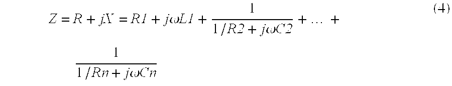
where ω=2πf is the angular frequency. The inductance and the capacitances are eliminated from this expression by writing them in terms of time constants 
The result is 
Multiplying both sides of equation (6) by the product (1+jωτ2) . . . (1+jωτn) clears the fractions and yields
For n=3, equation (7) reduces to
Equation (7) is divided into two equations by multiplying the terms out, separating them into real and imaginary parts, and then separately equating real to real, and imaginary to imaginary. For n=3, this procedure leads to
Real Part:
Imaginary Part:
Equations (9) and (10) are nonlinear since the 2n unknown resistances and time constants appear as combinations of products. I attack this formidable problem by defining a new set of 2n intermediate variables. These new variables are the various combinations of the model's resistances and time constants that multiply functions of battery resistance, battery reactance, and frequency. For n=3, the six intermediate variables are defined by
When expressed in terms of these new variables, equations (9) and (10) are linear. At the angular spot frequency ωk, these two equations are
In general, equations such as (12) and (13) comprise a pair of linear inhomogeneous equations for the 2n intermediate variables, ψ1, . . . , ψ2n. Even though linear, such equations are still not solvable since they contain an insufficient number of relationships between variables. However, by evaluating the complex impedance at n discrete frequencies, ω1. . . ωn, the two equations expand into a solvable set of 2n linear inhomogeneous equations in 2n unknowns. Such a system can be solved by the well-known method known as Cramer's rule. Cramer's rule expresses the 2n solutions, ψ1, . . . , ψ2n, as ratios of determinants having 2n columns and 2n rows. For n=3, these six solutions are of the form
where AD and A1. . . A6 are (6×6) determinants given by 
The determinants disclosed in equations (15)-(21) can be systematically evaluated from spot-frequency immittance measurements by well-known numerical expansion techniques. Once their values are known, the intermediate variables ψ1, . . . , ψ6 follow from equations (14). The defining equations of the intermediate variables, equations (11a)-(11f), are then combined in particular ways to evaluate the elements of the equivalent circuit model.
The technique proceeds as follows. One first combines the defining equations for n−1 of the 2n intermediate variables to yield an equation for the n−1 capacitive time constants τ2, . . . , τn. These n−1 equations are identified by not containing resistances. For example, for n=3, I combine equation (11a) and equation (11b) to obtain the following quadratic equation:
The two roots of equation (22) are given by the well-known quadratic formula 
For the general case of arbitrary n, combining the n−1 defining equations that contain no resistances leads to the following polynomial equation of order n−1:
The n−1 roots of equation (24) are the capacitive time constants τ2, . . . , τn. Although general formulas similar to equation (23) do not exist to solve higher order polynomial equations, the roots of equation (24) can always be found using well-known numerical root-finding algorithms.
Once the capacitive time constants have been determined, the inductive time constant τ1 follows by eliminating R1 from the two defining equations for intermediate variables that are proportional to R1. For example, with n=3, I combine equations (11e) and (11f) to obtain
For the general case of arbitrary n, the expression for τ1 is of the form
Thus, in principle, all n time constants are known.
In general, there are 2n equations defining the 2n intermediate variables. The first n−1 of these equations contain no resistances and are employed to determine the capacitive time constants. Two of the remaining n+1 equations are employed to determine the inductive time constant. By choosing either one of these two equations, along with all of the remaining n−1 unused equations, one obtains a set of n linear inhomogeneous equations in the n unknowns R1, . . . , Rn. Cramer's rule can then be invoked to solve this system for the values of these n resistances. For example, with n=3, I use equations (16c), (16d), and (16f) to obtain the following set of three linear equations in three unknowns: 
Cramer's rule yields the following three solutions: 
Thus, in principle, all n resistance values are known.
Finally, I invert equations (5) to determine the single inductance value and the n−1 capacitance values from the n known time constants and the n known resistance values 
This completes the disclosure of my method for determining the 2n element values. Although n is unrestricted in principle, the problem of expanding large determinants will probably limit n to the range 2≦n≦8. In summary, the steps are:
1. One first finds 2n intermediate variables by evaluating 2n ratios of determinants comprising 2n columns and 2n rows. The determinants comprise sums and differences of products combining the n spot frequencies with real and imaginary parts of impedance or admittance at the n spot frequencies.
2. The n−1 capacitive time constants are found as roots of a polynomial equation of order n−1. The polynomial's coefficients comprise n−1 of the 2n intermediate variables whose defining equations contain no resistances.
3. The inductive time constant is determined from an equation containing the capacitive time constants found in step 2 along with the ratio of the two intermediate variables proportional to R1.
4. The n resistances are determined by evaluating n ratios of (n×n) determinants. Elements of these determinants contain the n time constants found in steps 2 and 3 along with n of the remaining n+1 intermediate variables not employed in step 2.
5. Finally, the one inductance and the n−1 capacitances are evaluated by combining each of the n resistances with a corresponding time constant.
In practice, this procedure is readily implemented in software.
The exact procedure disclosed above can be simplified by choosing one of the n spot frequencies, say ωn, to be sufficiently high that the impedance of the series chain of R-C subcircuits is negligibly small at this frequency. A preliminary measurement of Z(ωn) then gives approximations to R1 and L1 directly. Subtracting R1+jωkL1 from the total measured impedance Z(ωk) at each of the n−1 remaining spot frequencies and equating this result to the theoretical impedance of the R-C subcircuit chain at each frequency leads to a system of 2n−2 equations in 2n−2 unknowns. Solving for the appropriate 2n−2 intermediate variables by Cramer's rule involves evaluating determinants that are fewer in number and smaller in size than the determinants evaluated in the exact procedure disclosed above.
FIG. 3 discloses an equivalent circuit model derived from FIG. 2 by letting n=2. This simple model is essentially the one discussed by Willihnganz and Rohner and by DeBardelaben in the publications cited earlier. By using the exact procedure disclosed above, I evaluated the four linear circuit elements of the model of FIG. 3 from the experimental data disclosed in FIGS. 1a and 1 b at the two spot frequencies f1=5 Hz and f2=1000 Hz. The results of this evaluation procedure are displayed in Table 1.
| TABLE 1 |
| Model Element Values for n = 2 |
| R1 = 4.388 mΩ | R2 = 12.987 mΩ | ||
| L1 = 0.3885 μH | C2 = 2.602 F | ||
Theoretical curves of the real and imaginary parts of admittance as functions of frequency were calculated for the model of FIG. 3 by assuming the element values displayed in Table 1. The theoretical curves are plotted along with the measured curves for comparison in FIGS. 4a and 4 b. One sees that the experimental and theoretical curves agree exactly at the two spot frequencies as would be anticipated. However, away from the spot frequencies the agreement is seen to be poor. This indicates that the model of FIG. 3 does not adequately represent the battery over this frequency range.
Much better agreement is obtained with the n=3 model depicted in FIG. 5. Using the exact procedures disclosed above, I evaluated the six linear circuit elements of the model of FIG. 5 from the experimental data disclosed in FIGS. 1a and 1 b at the three spot frequencies f1=5 HZ, f2=70 Hz, and f3=1000 Hz. The results are displayed in Table 2.
| TABLE 2 |
| Model Element Values for n = 3 |
| R1 = 4.381 mΩ | R2 = 1.227 mΩ | R3 = 13.257 mΩ | ||
| L1 = 0.411 μH | C2 = 1.812 F | C3 = 3.14 F | ||
Theoretical curves of the real and imaginary parts of admittance as functions of frequency were calculated for the model of FIG. 5 by assuming the element values displayed in Table 2. These curves are plotted along with the measured curves for comparison in FIGS. 6a and 6 b. Once again one sees that the experimental and theoretical curves agree exactly at the spot frequencies. Away from these frequencies, however, the agreement is seen to also be very good. Such good agreement proves the model of FIG. 5 to be an excellent representation of the battery over the frequency range from 5 Hz to 1000 Hz. Accordingly, the n=3 model much more closely describes actual processes within the battery than does the n=2 model.
The excellent agreement between the experimental curves and the theoretical predictions of the model means that Table 2 contains virtually the same information about the battery as does the continuous spectrum of complex admittance displayed in FIGS. 1a and 1 b. However, Table 2 provides this information in a much more concise form that is far easier to store, analyze, and manipulate. Accordingly, the information displayed in Table 2 may itself comprise the desired result.
Moreover, since the circuit elements defined in the extended model closely describe actual processes occurring within the battery, a predetermined relationship can additionally be invoked if desired, to implement a final step of determining one or more additional battery property. For example, I have found that the battery's cold-cranking ampere (CCA) capacity is quite accurately given by
where R1 is expressed in milliohms. Thus, the battery whose complex admittance spectrum is disclosed in FIGS. 1a and 1 b is capable of supplying 608 cold-cranking amperes. This important information is not at all obvious from the spectral plots of FIGS. 1a and 1 b. Other electrical properties such as state-of-charge and ampere-hour capacity; chemical properties such as ion concentration and plate composition; and physical properties such as battery temperature and effective plate area, find similar expression in the complex immittance spectra of the battery and may be determined in a comparable manner.
FIG. 7 discloses a block diagram of a device for determining cell/battery properties from spot-frequency complex immittance according to the present invention. Measuring circuitry 10 electrically couples to cell/battery 20 by means of current-carrying contacts A and B and voltage-sensing contacts C and D. Measuring circuitry 10 passes a periodic time-varying current i(t) through contacts A and B and senses a periodic time-varying voltage v(t) across contacts C and D. By appropriately processing and combining i(t) and v(t), measuring circuitry 10 determines real and imaginary parts of complex immittance at a measuring frequency fk; where fk is a discrete frequency component of waveforms i(t) and v(t).
In practice, a single microprocessor or microcontroller running an appropriate software program can perform the functions of both control circuitry 30 and computation circuitry 50 as well as much of the function of measuring circuitry 10. Microprocessor controlled impedance measuring apparatus is disclosed in a copending U.S. patent application.
FIG. 8 discloses a flow chart depicting a control algorithm for the invention embodiment of FIG. 7. Upon entering the procedure at 100, control circuitry 30 initializes a counter at 105 used to identify each spot frequency fk. At 110, control circuitry 30 commands measuring circuitry 10 to excite the cell/battery with a periodic signal having a sinusoidal component at frequency fk and to determine the real and imaginary parts of complex immittance at this frequency. At decision block 115, control circuitry 30 determines whether this procedure has been performed at all of the desired spot frequencies. If the answer is no, the counter is incremented at 120 and the procedure repeated at a new frequency. If yes, control circuitry 30 commands computation circuitry 50 to begin the computation at 125. Computation circuitry 50 begins at step 130 by determining the 2n intermediate variables from the values of real and imaginary parts of complex immittance at the n spot frequencies along with the n spot frequency values themselves. The 2n frequency-independent model elements are then evaluated from the 2n intermediate variable values at step 135. Finally, at optional step 140 computation circuitry 50 can, if desired, invoke an additional predetermined relationship between one or more of the model elements and a desired cell/battery property to determine the desired property.
This completes the disclosure of my invention. The method and apparatus are efficient, accurate, and easily implemented with a microcontroller or microprocessor. The invention is quite general and suitable for a wide variety of diagnostic applications ranging from hand-held battery test instruments to “smart” battery chargers and battery “fuel gauges” in electric vehicles. Although a lead-acid storage battery was used as an example to teach the method, the disclosed invention is equally applicable to both primary and secondary cells and batteries, and to cells/batteries employed in a variety of other applications and/or employing other chemical systems.
The present invention has been described with reference to a preferred embodiment. However, workers skilled in the art will recognize that changes may be made in form and detail without departing from the spirit and scope of the invention.
Claims (25)
1. Apparatus for determining an electrical, chemical, or physical property of an electrochemical cell or battery comprising:
measuring circuitry adapted to couple to said cell or battery and adapted to determine a real part and an imaginary part of complex immittance of said cell or battery at a measurement frequency;
control circuitry coupled to said measuring circuitry and adapted to command said measuring circuitry to select each one of n said measurement frequencies thereby defining n said real parts, n said imaginary parts and n said measurement frequencies where n is an integer number equal to or greater than two; and,
computation circuitry coupled to said measuring circuitry and to said control circuitry and adapted to numerically combine values of said n real parts, said n imaginary parts, and said n measurement frequencies to evaluate one or more elements of a 2n-element equivalent circuit model and further adapted to determine said electrical, chemical, or physical property from one or more values of said elements.
2. Apparatus as in claim 1 wherein n is equal to three.
3. Apparatus as in claim 1 wherein said control circuitry and said computation circuitry comprise a microprocessor or microcontroller running a software program adapted to select each one of said n measurement frequencies and further adapted to numerically combine values of said n real parts, said n imaginary parts, and said n measurement frequencies to evaluate said elements, and to determine said electrical, chemical, or physical property of said electrochemical cell or battery from one or more values of said elements.
4. Apparatus as in claim 1 wherein said electrical, chemical, or physical property is an electrical property comprising a number representative of the ability of said electrochemical cell or battery to supply current to a load.
5. Apparatus as in claim 4 wherein said device determines said number from the value of a particular resistive element included in said equivalent circuit model.
6. Apparatus as in claim 5 wherein said number is inversely proportional to said value of said particular resistive element.
7. Apparatus as in claim 4 wherein said number is expressed in units of cold-cranking amperes.
8. Apparatus for assessing the ability of an electrochemical cell or battery to supply current to a load comprising:
measuring circuitry adapted to couple to said cell or battery and adapted to pass a periodic current through said cell or battery, to sense a periodic voltage across said cell or battery, and to determine a real part and an imaginary part of complex immittance of said cell or battery at a measurement frequency comprising a component frequency of said periodic current and said periodic voltage;
control circuitry coupled to said measuring circuitry and adapted to command said measuring circuitry to select each one of n said measurement frequencies thereby defining n said real parts, n said imaginary parts and n said measurement frequencies where n is an integer number equal to or greater than two; and,
computation circuitry coupled to said measuring circuitry and to said control circuitry and adapted to numerically combine values of said n real parts, said n imaginary parts, and said n measurement frequencies to evaluate one or more elements of a 2n-element equivalent circuit model and further adapted to assess said ability from values of one or more said elements.
9. Apparatus as in claim 8 wherein n is equal to three.
10. Apparatus as in claim 8 wherein said control circuitry and said computation circuitry comprise a microprocessor or microcontroller running a software program adapted to select each one of said n measurement frequencies and further adapted to numerically combine values of said n real parts, said n imaginary parts, and said n measurement frequencies to evaluate said elements and assess said ability.
11. Apparatus as in claim 8 wherein said device assesses said ability from the value of a particular resistive element included in said equivalent circuit model.
12. Apparatus as in claim 11 wherein said ability is expressed as a number that is inversely proportional to the value of said particular resistive element.
13. Apparatus as in claim 12 wherein said number is expressed in units of cold-cranking amperes.
14. A method for determining an electrical, chemical, or physical property of an electrochemical cell or battery comprising:
measuring real and imaginary parts of complex immittance of said electrochemical cell or battery at n discrete frequencies where n is an integer number equal to or greater than two;
evaluating linear electrical elements of an equivalent circuit model of said electrochemical cell or battery from said n discrete frequencies and said complex immittance at said n discrete frequencies, said circuit model comprising an interconnection of 2n linear electrical elements; and,
determining said electrical, chemical, or physical property of said electrochemical cell or battery from values of one or more said linear electrical elements.
15. A method as in claim 14 wherein n is equal to three.
16. A method as in claim 14 wherein said electrical, chemical, or physical property is an electrical property comprising a number representative of the ability of said electrochemical cell or battery to supply current to a load and the step of determining said electrical, chemical, or physical property from values of one or more said linear electrical elements comprises determining said number from the value of a particular resistive element of said equivalent circuit model.
17. A method as in claim 16 wherein said step of determining said electrical, chemical, or physical property comprises dividing said value of said particular resistive element into a constant number to determine said number representative of the ability of said electrochemical cell or battery to supply current to a load.
18. A method as in claim 17 wherein said number representative of the ability of said electrochemical cell or battery to supply current to a load is expressed in units of cold-cranking amperes.
19. A method for determining the ability of an electrochemical cell or battery to supply current to a load comprising:
measuring real and imaginary parts of complex immittance of said electrochemical cell or battery at n discrete frequencies where n is an integer number equal to or greater than two;
evaluating linear electrical elements of an equivalent circuit model of said electrochemical cell or battery from said n discrete frequencies and said complex immittance at said n discrete frequencies, said circuit model comprising an interconnection of 2n linear electrical elements; and,
determining said ability of said electrochemical cell or battery to supply current to a load from values of one or more of said linear electrical elements.
20. A method as in claim 19 wherein n is equal to three.
21. A method as in claim 19 wherein the step of determining said ability of said electrochemical cell or battery to supply current to a load comprises determining a number representative of said ability from the value of a particular resistive element of said equivalent circuit model.
22. A method as in claim 21 wherein the step of determining said ability of said electrochemical cell or battery to supply current to a load comprises dividing said value of said particular resistive element into a constant number to determine said number representative of said ability.
23. A method as in claim 22 wherein said number representative of said ability to supply current to a load is expressed in units of cold-cranking amperes.
24. An apparatus for determining an electrical, chemical, or physical property of an electrochemical cell or battery adapted for performing the steps according to claim 14.
25. An apparatus for determining the ability of an electrochemical cell or battery to supply current to a load adapted for performing the steps according to claim 19.
Priority Applications (1)
| Application Number | Priority Date | Filing Date | Title |
|---|---|---|---|
| US09/491,509 US6222369B1 (en) | 1998-09-11 | 2000-01-26 | Method and apparatus for determining battery properties from complex impedance/admittance |
Applications Claiming Priority (2)
| Application Number | Priority Date | Filing Date | Title |
|---|---|---|---|
| US09/151,324 US6037777A (en) | 1998-09-11 | 1998-09-11 | Method and apparatus for determining battery properties from complex impedance/admittance |
| US09/491,509 US6222369B1 (en) | 1998-09-11 | 2000-01-26 | Method and apparatus for determining battery properties from complex impedance/admittance |
Related Parent Applications (1)
| Application Number | Title | Priority Date | Filing Date |
|---|---|---|---|
| US09/151,324 Continuation US6037777A (en) | 1998-09-11 | 1998-09-11 | Method and apparatus for determining battery properties from complex impedance/admittance |
Publications (1)
| Publication Number | Publication Date |
|---|---|
| US6222369B1 true US6222369B1 (en) | 2001-04-24 |
Family
ID=22538241
Family Applications (2)
| Application Number | Title | Priority Date | Filing Date |
|---|---|---|---|
| US09/151,324 Expired - Lifetime US6037777A (en) | 1998-09-11 | 1998-09-11 | Method and apparatus for determining battery properties from complex impedance/admittance |
| US09/491,509 Expired - Lifetime US6222369B1 (en) | 1998-09-11 | 2000-01-26 | Method and apparatus for determining battery properties from complex impedance/admittance |
Family Applications Before (1)
| Application Number | Title | Priority Date | Filing Date |
|---|---|---|---|
| US09/151,324 Expired - Lifetime US6037777A (en) | 1998-09-11 | 1998-09-11 | Method and apparatus for determining battery properties from complex impedance/admittance |
Country Status (8)
| Country | Link |
|---|---|
| US (2) | US6037777A (en) |
| EP (1) | EP1129343B1 (en) |
| JP (1) | JP2002525793A (en) |
| CN (1) | CN1225649C (en) |
| AU (1) | AU5821199A (en) |
| DE (1) | DE69938900D1 (en) |
| HK (1) | HK1040430B (en) |
| WO (1) | WO2000016083A1 (en) |
Cited By (113)
| Publication number | Priority date | Publication date | Assignee | Title |
|---|---|---|---|---|
| US6392414B2 (en) | 1997-01-13 | 2002-05-21 | Midtronics, Inc. | Electronic battery tester |
| US6417669B1 (en) | 2001-06-11 | 2002-07-09 | Keith S. Champlin | Suppressing interference in AC measurements of cells, batteries and other electrical elements |
| US6424158B2 (en) | 1998-07-27 | 2002-07-23 | Midtronics, Inc. | Apparatus and method for carrying out diagnostic tests on batteries and for rapidly charging batteries |
| US6441585B1 (en) | 1999-06-16 | 2002-08-27 | Midtronics, Inc. | Apparatus and method for testing rechargeable energy storage batteries |
| US6445158B1 (en) | 1996-07-29 | 2002-09-03 | Midtronics, Inc. | Vehicle electrical system tester with encoded output |
| US6456045B1 (en) | 1999-04-16 | 2002-09-24 | Midtronics, Inc. | Integrated conductance and load test based electronic battery tester |
| US6466025B1 (en) | 2000-01-13 | 2002-10-15 | Midtronics, Inc. | Alternator tester |
| US6466026B1 (en) | 2001-10-12 | 2002-10-15 | Keith S. Champlin | Programmable current exciter for measuring AC immittance of cells and batteries |
| US6469511B1 (en) | 2001-07-18 | 2002-10-22 | Midtronics, Inc. | Battery clamp with embedded environment sensor |
| US20020171428A1 (en) * | 1997-11-03 | 2002-11-21 | Bertness Kevin I. | Electronic battery tester with network communication |
| US6495990B2 (en) | 1999-09-01 | 2002-12-17 | Keith S. Champlin | Method and apparatus for evaluating stored charge in an electrochemical cell or battery |
| US20030001579A1 (en) * | 1996-07-29 | 2003-01-02 | Bertness Kevin I. | Method and apparatus for auditing a battery test |
| US20030038637A1 (en) * | 1997-11-03 | 2003-02-27 | Bertness Kevin I. | Automotive vehicle electrical system diagnostic device |
| US6544078B2 (en) | 2001-07-18 | 2003-04-08 | Midtronics, Inc. | Battery clamp with integrated current sensor |
| US6556019B2 (en) | 1999-04-30 | 2003-04-29 | Midtronics, Inc. | Electronic battery tester |
| US20030088375A1 (en) * | 2001-10-17 | 2003-05-08 | Bertness Kevin I. | Electronic battery tester with relative test output |
| US6566883B1 (en) | 1999-11-01 | 2003-05-20 | Midtronics, Inc. | Electronic battery tester |
| US6586941B2 (en) | 2000-03-27 | 2003-07-01 | Midtronics, Inc. | Battery tester with databus |
| US20030124417A1 (en) * | 1999-04-08 | 2003-07-03 | Bertness Kevin I. | Battery test module |
| EP1339122A2 (en) * | 2002-02-20 | 2003-08-27 | VARTA Microbattery GmbH | Process for manufacturing galvanic elements |
| US20030173971A1 (en) * | 2002-03-14 | 2003-09-18 | Bertness Kevin I. | Electronic battery tester with battery failure temperature determination |
| US20030184258A1 (en) * | 2001-06-22 | 2003-10-02 | Vonderhaar J. David | Booster pack with storage capacitor |
| US6633165B2 (en) | 1997-11-03 | 2003-10-14 | Midtronics, Inc. | In-vehicle battery monitor |
| WO2003093849A1 (en) * | 2002-04-29 | 2003-11-13 | Cadex Electronics Inc. | Multiple model systems and methods for testing electrochemical systems |
| US6696819B2 (en) | 2002-01-08 | 2004-02-24 | Midtronics, Inc. | Battery charge control device |
| US20040036443A1 (en) * | 2000-03-27 | 2004-02-26 | Bertness Kevin I. | Modular battery tester for scan tool |
| US20040046566A1 (en) * | 2002-09-05 | 2004-03-11 | Klang James K. | Electronic battery tester configured to predict a load test result |
| US6707303B2 (en) | 1999-04-08 | 2004-03-16 | Midtronics, Inc. | Electronic battery tester |
| US6737831B2 (en) | 1999-09-01 | 2004-05-18 | Keith S. Champlin | Method and apparatus using a circuit model to evaluate cell/battery parameters |
| US20040104728A1 (en) * | 1996-07-29 | 2004-06-03 | Bertness Kevin I. | Alternator tester with encoded output |
| US6759849B2 (en) | 2000-03-27 | 2004-07-06 | Kevin I. Bertness | Battery tester configured to receive a removable digital module |
| US20040140904A1 (en) * | 2003-01-22 | 2004-07-22 | Bertness Kevin I. | Apparatus and method for protecting a battery from overdischarge |
| US20040157113A1 (en) * | 2002-12-31 | 2004-08-12 | Midtronics, Inc. | Apparatus and method for predicting the remaining discharge time of a battery |
| US6781382B2 (en) | 2002-12-05 | 2004-08-24 | Midtronics, Inc. | Electronic battery tester |
| US6788025B2 (en) | 2001-06-22 | 2004-09-07 | Midtronics, Inc. | Battery charger with booster pack |
| US6795782B2 (en) | 1999-04-08 | 2004-09-21 | Midtronics, Inc. | Battery test module |
| US20040189308A1 (en) * | 2003-03-25 | 2004-09-30 | Bertness Kevin I. | Electronic battery tester |
| US20040251876A1 (en) * | 2001-06-22 | 2004-12-16 | Midtronics, Inc. | Apparatus and method for counteracting self discharge in a storage battery |
| US20050048336A1 (en) * | 2003-07-24 | 2005-03-03 | Yasuo Takebe | Fuel cell system, and operation and program for same |
| US20050073314A1 (en) * | 2003-10-03 | 2005-04-07 | Midtronics, Inc. | Electronic battery tester/charger with integrated battery cell temperature measurement device |
| US20050099185A1 (en) * | 2003-11-11 | 2005-05-12 | Klang James K. | Apparatus and method for simulating a battery tester with a fixed resistance load |
| US20050206346A1 (en) * | 2004-03-18 | 2005-09-22 | Midtronics, Inc. | Battery charger with automatic customer notification system |
| US20060125482A1 (en) * | 2004-12-09 | 2006-06-15 | Midtronics, Inc. | Apparatus and method for predicting battery capacity and fitness for service from a battery dynamic parameter and a recovery voltage differential |
| DE112006002329T5 (en) | 2005-08-29 | 2008-07-10 | Midtronics, Inc., Willowbrook | Diagnostic device for electrical installations of motor vehicles |
| US7688074B2 (en) | 1997-11-03 | 2010-03-30 | Midtronics, Inc. | Energy management system for automotive vehicle |
| US7705602B2 (en) | 1997-11-03 | 2010-04-27 | Midtronics, Inc. | Automotive vehicle electrical system diagnostic device |
| US7706991B2 (en) | 1996-07-29 | 2010-04-27 | Midtronics, Inc. | Alternator tester |
| US7710119B2 (en) | 2004-12-09 | 2010-05-04 | Midtronics, Inc. | Battery tester that calculates its own reference values |
| DE102009051235A1 (en) | 2008-10-30 | 2010-05-06 | Midtronics, Inc., Willowbrook | Vehicle electrical system tester for testing electrical system of vehicle has test connection that thaws current from battery along path through wire and returns current to battery, to measure electrical parameter of wire with sensor |
| US7728597B2 (en) | 2000-03-27 | 2010-06-01 | Midtronics, Inc. | Electronic battery tester with databus |
| US7774151B2 (en) | 1997-11-03 | 2010-08-10 | Midtronics, Inc. | Wireless battery monitor |
| US7772850B2 (en) | 2004-07-12 | 2010-08-10 | Midtronics, Inc. | Wireless battery tester with information encryption means |
| US7777612B2 (en) | 2004-04-13 | 2010-08-17 | Midtronics, Inc. | Theft prevention device for automotive vehicle service centers |
| US7791348B2 (en) | 2007-02-27 | 2010-09-07 | Midtronics, Inc. | Battery tester with promotion feature to promote use of the battery tester by providing the user with codes having redeemable value |
| US7808375B2 (en) | 2007-04-16 | 2010-10-05 | Midtronics, Inc. | Battery run down indicator |
| US7977914B2 (en) | 2003-10-08 | 2011-07-12 | Midtronics, Inc. | Battery maintenance tool with probe light |
| US7999505B2 (en) | 1997-11-03 | 2011-08-16 | Midtronics, Inc. | In-vehicle battery monitor |
| WO2011159455A1 (en) | 2010-06-18 | 2011-12-22 | Midtronics, Inc. | Battery maintenance device with thermal buffer |
| US8198900B2 (en) | 1996-07-29 | 2012-06-12 | Midtronics, Inc. | Automotive battery charging system tester |
| US8203345B2 (en) | 2007-12-06 | 2012-06-19 | Midtronics, Inc. | Storage battery and battery tester |
| US8237448B2 (en) | 2000-03-27 | 2012-08-07 | Midtronics, Inc. | Battery testers with secondary functionality |
| US8306690B2 (en) | 2007-07-17 | 2012-11-06 | Midtronics, Inc. | Battery tester for electric vehicle |
| US8344685B2 (en) | 2004-08-20 | 2013-01-01 | Midtronics, Inc. | System for automatically gathering battery information |
| US8436619B2 (en) | 2004-08-20 | 2013-05-07 | Midtronics, Inc. | Integrated tag reader and environment sensor |
| US8442877B2 (en) | 2004-08-20 | 2013-05-14 | Midtronics, Inc. | Simplification of inventory management |
| US8513949B2 (en) | 2000-03-27 | 2013-08-20 | Midtronics, Inc. | Electronic battery tester or charger with databus connection |
| US8674711B2 (en) | 2003-09-05 | 2014-03-18 | Midtronics, Inc. | Method and apparatus for measuring a parameter of a vehicle electrical system |
| US8738309B2 (en) | 2010-09-30 | 2014-05-27 | Midtronics, Inc. | Battery pack maintenance for electric vehicles |
| US8872517B2 (en) | 1996-07-29 | 2014-10-28 | Midtronics, Inc. | Electronic battery tester with battery age input |
| US8958998B2 (en) | 1997-11-03 | 2015-02-17 | Midtronics, Inc. | Electronic battery tester with network communication |
| US9018958B2 (en) | 2003-09-05 | 2015-04-28 | Midtronics, Inc. | Method and apparatus for measuring a parameter of a vehicle electrical system |
| WO2015089249A1 (en) | 2013-12-12 | 2015-06-18 | Midtronics, Inc. | Battery tester and battery registration tool |
| EP2897229A1 (en) | 2014-01-16 | 2015-07-22 | Midtronics, Inc. | Battery clamp with endoskeleton design |
| US9201120B2 (en) | 2010-08-12 | 2015-12-01 | Midtronics, Inc. | Electronic battery tester for testing storage battery |
| US9229062B2 (en) | 2010-05-27 | 2016-01-05 | Midtronics, Inc. | Electronic storage battery diagnostic system |
| US9244100B2 (en) | 2013-03-15 | 2016-01-26 | Midtronics, Inc. | Current clamp with jaw closure detection |
| US9255955B2 (en) | 2003-09-05 | 2016-02-09 | Midtronics, Inc. | Method and apparatus for measuring a parameter of a vehicle electrical system |
| US9274157B2 (en) | 2007-07-17 | 2016-03-01 | Midtronics, Inc. | Battery tester for electric vehicle |
| US9312575B2 (en) | 2013-05-16 | 2016-04-12 | Midtronics, Inc. | Battery testing system and method |
| WO2016123075A1 (en) | 2015-01-26 | 2016-08-04 | Midtronics, Inc. | Alternator tester |
| US9425487B2 (en) | 2010-03-03 | 2016-08-23 | Midtronics, Inc. | Monitor for front terminal batteries |
| WO2016176405A1 (en) | 2015-04-29 | 2016-11-03 | Midtronics, Inc. | Calibration and programming of in-vehicle battery sensors |
| US9496720B2 (en) | 2004-08-20 | 2016-11-15 | Midtronics, Inc. | System for automatically gathering battery information |
| US9588185B2 (en) | 2010-02-25 | 2017-03-07 | Keith S. Champlin | Method and apparatus for detecting cell deterioration in an electrochemical cell or battery |
| US9851411B2 (en) | 2012-06-28 | 2017-12-26 | Keith S. Champlin | Suppressing HF cable oscillations during dynamic measurements of cells and batteries |
| US9851414B2 (en) | 2004-12-21 | 2017-12-26 | Battelle Energy Alliance, Llc | Energy storage cell impedance measuring apparatus, methods and related systems |
| US9966676B2 (en) | 2015-09-28 | 2018-05-08 | Midtronics, Inc. | Kelvin connector adapter for storage battery |
| US10046649B2 (en) | 2012-06-28 | 2018-08-14 | Midtronics, Inc. | Hybrid and electric vehicle battery pack maintenance device |
| CN108414942A (en) * | 2017-02-09 | 2018-08-17 | 丰田自动车株式会社 | Battery status estimating device |
| US10222397B2 (en) | 2014-09-26 | 2019-03-05 | Midtronics, Inc. | Cable connector for electronic battery tester |
| US10345384B2 (en) | 2016-03-03 | 2019-07-09 | Battelle Energy Alliance, Llc | Device, system, and method for measuring internal impedance of a test battery using frequency response |
| WO2019147546A1 (en) | 2018-01-23 | 2019-08-01 | Midtronics, Inc. | High capacity battery balancer |
| WO2019147549A1 (en) | 2018-01-23 | 2019-08-01 | Midtronics, Inc. | Hybrid and electric vehicle battery maintenance device |
| US10379168B2 (en) | 2007-07-05 | 2019-08-13 | Battelle Energy Alliance, Llc | Apparatuses and methods for testing electrochemical cells by measuring frequency response |
| US10429449B2 (en) | 2011-11-10 | 2019-10-01 | Midtronics, Inc. | Battery pack tester |
| US10473555B2 (en) | 2014-07-14 | 2019-11-12 | Midtronics, Inc. | Automotive maintenance system |
| US10481214B2 (en) * | 2017-01-30 | 2019-11-19 | Infineon Technologies Ag | Battery temperature detection |
| US10608353B2 (en) | 2016-06-28 | 2020-03-31 | Midtronics, Inc. | Battery clamp |
| US10843574B2 (en) | 2013-12-12 | 2020-11-24 | Midtronics, Inc. | Calibration and programming of in-vehicle battery sensors |
| WO2021092109A1 (en) | 2019-11-05 | 2021-05-14 | Midtronics, Inc. | System for charging a series of connected batteries |
| US11054481B2 (en) | 2019-03-19 | 2021-07-06 | Battelle Energy Alliance, Llc | Multispectral impedance determination under dynamic load conditions |
| US11054480B2 (en) | 2016-10-25 | 2021-07-06 | Midtronics, Inc. | Electrical load for electronic battery tester and electronic battery tester including such electrical load |
| US11325479B2 (en) | 2012-06-28 | 2022-05-10 | Midtronics, Inc. | Hybrid and electric vehicle battery maintenance device |
| US11422102B2 (en) | 2020-01-10 | 2022-08-23 | Dynexus Technology, Inc. | Multispectral impedance measurements across strings of interconnected cells |
| US11474153B2 (en) | 2019-11-12 | 2022-10-18 | Midtronics, Inc. | Battery pack maintenance system |
| US11486930B2 (en) | 2020-01-23 | 2022-11-01 | Midtronics, Inc. | Electronic battery tester with battery clamp storage holsters |
| US11513160B2 (en) | 2018-11-29 | 2022-11-29 | Midtronics, Inc. | Vehicle battery maintenance device |
| US11519969B2 (en) | 2020-01-29 | 2022-12-06 | Dynexus Technology, Inc. | Cross spectral impedance assessment for cell qualification |
| US11566972B2 (en) | 2019-07-31 | 2023-01-31 | Midtronics, Inc. | Tire tread gauge using visual indicator |
| US11650259B2 (en) | 2010-06-03 | 2023-05-16 | Midtronics, Inc. | Battery pack maintenance for electric vehicle |
| US11668779B2 (en) | 2019-11-11 | 2023-06-06 | Midtronics, Inc. | Hybrid and electric vehicle battery pack maintenance device |
| US11709219B2 (en) | 2016-04-25 | 2023-07-25 | Dynexus Technology, Inc. | Method of calibrating impedance measurements of a battery |
| US11740294B2 (en) | 2010-06-03 | 2023-08-29 | Midtronics, Inc. | High use battery pack maintenance |
Families Citing this family (103)
| Publication number | Priority date | Publication date | Assignee | Title |
|---|---|---|---|---|
| US7003410B2 (en) * | 1996-07-29 | 2006-02-21 | Midtronics, Inc. | Electronic battery tester with relative test output |
| US6351102B1 (en) | 1999-04-16 | 2002-02-26 | Midtronics, Inc. | Automotive battery charging system tester |
| US6331762B1 (en) | 1997-11-03 | 2001-12-18 | Midtronics, Inc. | Energy management system for automotive vehicle |
| US6081098A (en) | 1997-11-03 | 2000-06-27 | Midtronics, Inc. | Method and apparatus for charging a battery |
| US6329793B1 (en) | 1996-07-29 | 2001-12-11 | Midtronics, Inc. | Method and apparatus for charging a battery |
| US6332113B1 (en) | 1996-10-07 | 2001-12-18 | Midtronics, Inc. | Electronic battery tester |
| US6262563B1 (en) * | 1998-09-11 | 2001-07-17 | Keith S. Champlin | Method and apparatus for measuring complex admittance of cells and batteries |
| US6037777A (en) * | 1998-09-11 | 2000-03-14 | Champlin; Keith S. | Method and apparatus for determining battery properties from complex impedance/admittance |
| US6294896B1 (en) | 1998-09-11 | 2001-09-25 | Keith S. Champlin | Method and apparatus for measuring complex self-immitance of a general electrical element |
| KR100395516B1 (en) * | 1998-11-19 | 2003-12-18 | 금호석유화학 주식회사 | Method and apparatus for digitizing characteristic factor of power storage device using nonlinear equivalent circuit model |
| US7505856B2 (en) * | 1999-04-08 | 2009-03-17 | Midtronics, Inc. | Battery test module |
| US7058525B2 (en) * | 1999-04-08 | 2006-06-06 | Midtronics, Inc. | Battery test module |
| US6316914B1 (en) | 1999-05-05 | 2001-11-13 | Midtronics, Inc. | Testing parallel strings of storage batteries |
| US6137269A (en) | 1999-09-01 | 2000-10-24 | Champlin; Keith S. | Method and apparatus for electronically evaluating the internal temperature of an electrochemical cell or battery |
| US6363303B1 (en) | 1999-11-01 | 2002-03-26 | Midtronics, Inc. | Alternator diagnostic system |
| DE19959019A1 (en) * | 1999-12-08 | 2001-06-13 | Bosch Gmbh Robert | Method for status detection of an energy store |
| US6225808B1 (en) | 2000-02-25 | 2001-05-01 | Midtronics, Inc. | Test counter for electronic battery tester |
| US7598744B2 (en) * | 2000-03-27 | 2009-10-06 | Midtronics, Inc. | Scan tool for electronic battery tester |
| US7598743B2 (en) * | 2000-03-27 | 2009-10-06 | Midtronics, Inc. | Battery maintenance device having databus connection |
| US6304087B1 (en) | 2000-09-05 | 2001-10-16 | Midtronics, Inc. | Apparatus for calibrating electronic battery tester |
| US6906523B2 (en) * | 2000-09-14 | 2005-06-14 | Midtronics, Inc. | Method and apparatus for testing cells and batteries embedded in series/parallel systems |
| US6519539B1 (en) | 2000-09-29 | 2003-02-11 | Hydrogenics Corporation | Measurement of fuel cell impedance |
| US6816797B2 (en) * | 2000-09-29 | 2004-11-09 | Hydrogenics Corporation | System and method for measuring fuel cell voltage and high frequency resistance |
| US6362601B1 (en) * | 2000-11-17 | 2002-03-26 | Curtis Instruments, Inc. | Method of battery charge restoration based on estimated battery plate deterioration and/or based on battery state of health |
| US6794067B1 (en) | 2000-11-29 | 2004-09-21 | Mti Microfuel Cells, Inc. | Fuel cell control and measurement apparatus and method, using dielectric constant measurements |
| DE10205120B4 (en) * | 2001-02-13 | 2004-12-16 | Akkumulatorenfabrik Moll Gmbh & Co. Kg | Method and device for determining the internal resistance of a battery, in particular a starter battery for a motor vehicle |
| US6369577B1 (en) | 2001-03-02 | 2002-04-09 | Dhc Specialty Corp. | Electronic battery tester |
| DE10121962A1 (en) * | 2001-05-05 | 2002-11-07 | Vb Autobatterie Gmbh | Energy management system for motor vehicle on-board electrical system controls energy distribution taking into account current generation, storage, consumption component efficiencies |
| DE10126891A1 (en) * | 2001-06-01 | 2002-12-05 | Vb Autobatterie Gmbh | Predicting electrochemical element load capacity involves correcting equivalent circuit input voltage w.r.t measured voltage using function with logarithmic current dependency as nonlinear term |
| US7501795B2 (en) * | 2001-06-22 | 2009-03-10 | Midtronics Inc. | Battery charger with booster pack |
| US6941234B2 (en) * | 2001-10-17 | 2005-09-06 | Midtronics, Inc. | Query based electronic battery tester |
| US6727708B1 (en) | 2001-12-06 | 2004-04-27 | Johnson Controls Technology Company | Battery monitoring system |
| DE10210516B4 (en) | 2002-03-09 | 2004-02-26 | Vb Autobatterie Gmbh | Method and device for determining the functionality of a storage battery |
| DE10215071A1 (en) * | 2002-04-05 | 2003-10-30 | Vb Autobatterie Gmbh | Method for determining the wear of an electrochemical energy store and energy store |
| WO2003098769A2 (en) * | 2002-05-17 | 2003-11-27 | Greenlight Power Technologies, Inc. | Methods and apparatus for indicating a fault condition in fuel cells and fuel cell components |
| DE10224662C1 (en) * | 2002-06-03 | 2003-06-18 | Vb Autobatterie Gmbh | Battery charge state indicator has ball channel with upper bounding wall with opening for viewing rod tip aligned with reflective surface at transition to cylindrical surface of viewing rod |
| US7474228B2 (en) * | 2002-06-19 | 2009-01-06 | Tarma, Llc | Battery monitor |
| US20030236656A1 (en) * | 2002-06-21 | 2003-12-25 | Johnson Controls Technology Company | Battery characterization system |
| KR100462661B1 (en) * | 2002-07-02 | 2004-12-20 | 금호석유화학 주식회사 | Method for evaluating their capacities by calculating mathematically specific elements among resistance elements of equivalent circuit model fitted from impedance spectrum of secondary batteries |
| DE10231700B4 (en) * | 2002-07-13 | 2006-06-14 | Vb Autobatterie Gmbh & Co. Kgaa | Method for determining the aging state of a storage battery with regard to the removable amount of charge and monitoring device |
| FR2842305B1 (en) * | 2002-07-15 | 2004-10-01 | Inst Nat Polytech Grenoble | METHOD FOR DETERMINING THE INDEPENDENCE OF AN ELECTROCHEMICAL SYSTEM |
| DE10236958B4 (en) * | 2002-08-13 | 2006-12-07 | Vb Autobatterie Gmbh & Co. Kgaa | Method for determining the removable amount of charge of a storage battery and monitoring device for a storage battery |
| DE10240329B4 (en) * | 2002-08-31 | 2009-09-24 | Vb Autobatterie Gmbh & Co. Kgaa | Method for determining the charge quantity of a storage battery and monitoring device for a storage battery that can be taken from a fully charged storage battery |
| DE10252760B4 (en) * | 2002-11-13 | 2009-07-02 | Vb Autobatterie Gmbh & Co. Kgaa | Method for predicting the internal resistance of a storage battery and monitoring device for storage batteries |
| DE10253051B4 (en) | 2002-11-14 | 2005-12-22 | Vb Autobatterie Gmbh | Method for determining the charge acceptance of a storage battery |
| AU2003285252A1 (en) * | 2002-12-03 | 2004-06-23 | Hydrogenics Corporation | Method and apparatus for monitoring fuel cell voltages |
| CA2513421A1 (en) * | 2003-02-04 | 2004-08-19 | Hydrogenics Corporation | System and method for measuring internal resistance of electrochemical devices |
| KR100605123B1 (en) * | 2003-02-21 | 2006-07-28 | 주식회사 맥사이언스 | Method and device for evaluating deterioration characteristics of organic light emitting diode by measuring AC impedance |
| EP1480051A3 (en) * | 2003-05-19 | 2006-02-22 | Akkumulatorenfabrik Moll GmbH & Co. KG | Device and method for the determination of the high current capacity of a battery |
| DE10337064B4 (en) * | 2003-05-19 | 2006-05-11 | Akkumulatorenfabrik Moll Gmbh & Co. Kg | Determination method for the high-current carrying capacity of a battery, wherein parameters of a model of the battery impedance are determined and from them its current carrying ability predicted |
| US7408358B2 (en) * | 2003-06-16 | 2008-08-05 | Midtronics, Inc. | Electronic battery tester having a user interface to configure a printer |
| US6913483B2 (en) * | 2003-06-23 | 2005-07-05 | Midtronics, Inc. | Cable for electronic battery tester |
| US7319304B2 (en) * | 2003-07-25 | 2008-01-15 | Midtronics, Inc. | Shunt connection to a PCB of an energy management system employed in an automotive vehicle |
| GB0317513D0 (en) * | 2003-07-25 | 2003-08-27 | Megger Ltd | A method and apparatus for determining the complex impedance of an electrical component |
| DE10335930B4 (en) | 2003-08-06 | 2007-08-16 | Vb Autobatterie Gmbh & Co. Kgaa | Method for determining the state of an electrochemical storage battery |
| JP4297836B2 (en) * | 2003-09-10 | 2009-07-15 | 三洋電機株式会社 | Consumable parts and identification device thereof |
| US7595643B2 (en) * | 2003-11-11 | 2009-09-29 | Midtronics, Inc. | Apparatus and method for simulating a battery tester with a fixed resistance load |
| DE102004005478B4 (en) * | 2004-02-04 | 2010-01-21 | Vb Autobatterie Gmbh | Method for determining parameters for electrical states of a storage battery and monitoring device for this purpose |
| DE102004007904B4 (en) * | 2004-02-18 | 2008-07-03 | Vb Autobatterie Gmbh & Co. Kgaa | Method for determining at least one parameter for the state of an electrochemical storage battery and monitoring device |
| US7598699B2 (en) * | 2004-02-20 | 2009-10-06 | Midtronics, Inc. | Replaceable clamp for electronic battery tester |
| US7019542B2 (en) * | 2004-04-06 | 2006-03-28 | Cadex Electronics Inc. | Method and apparatus for battery testing |
| US7119686B2 (en) * | 2004-04-13 | 2006-10-10 | Midtronics, Inc. | Theft prevention device for automotive vehicle service centers |
| JP4383251B2 (en) * | 2004-05-26 | 2009-12-16 | 三洋電機株式会社 | A recording medium in which an equivalent circuit model of a storage element is recorded, a derivation program, its recording medium, a derivation device, a simulation program, its recording medium, a simulation device, a design method, a quality determination method, and a quality determination device. |
| US7106070B2 (en) * | 2004-07-22 | 2006-09-12 | Midtronics, Inc. | Broad-band low-inductance cables for making Kelvin connections to electrochemical cells and batteries |
| US20060038572A1 (en) * | 2004-08-20 | 2006-02-23 | Midtronics, Inc. | System for automatically gathering battery information for use during battery testing/charging |
| EP1820040A4 (en) * | 2004-11-29 | 2009-03-11 | Hydrogenics Corp | Systems and methods for detecting and indicating fault conditions in electrochemical cells |
| US7498767B2 (en) * | 2005-02-16 | 2009-03-03 | Midtronics, Inc. | Centralized data storage of condition of a storage battery at its point of sale |
| US7504830B2 (en) * | 2005-06-06 | 2009-03-17 | Associated Equipment Corp. | Dual load tester |
| DE102006024798B3 (en) * | 2006-05-27 | 2007-03-22 | Vb Autobatterie Gmbh & Co. Kgaa | Automotive lead-acid battery has electrolyte float gauge depth detector with ball cage |
| CN101374381B (en) * | 2007-08-20 | 2011-07-27 | 清华大学 | Method and system for matching radio frequency impedance |
| FR2929410B1 (en) * | 2008-03-28 | 2010-04-09 | Inst Francais Du Petrole | METHOD FOR ESTIMATING NON-MEASURABLE CHARACTERISTICS OF AN ELECTROCHEMICAL SYSTEM |
| JP5349250B2 (en) * | 2008-12-01 | 2013-11-20 | カルソニックカンセイ株式会社 | Battery model identification method |
| US20100295550A1 (en) * | 2009-02-20 | 2010-11-25 | National Semiconductor Corporation | Adaptive energy management terminal for a battery |
| US20100312744A1 (en) * | 2009-06-09 | 2010-12-09 | Toyota Motor Engineering & Manufacturing North America, Inc. | System for battery prognostics |
| FR2949565B1 (en) | 2009-09-02 | 2012-12-21 | Inst Francais Du Petrole | IMPROVED METHOD FOR ESTIMATING NON-MEASURABLE CHARACTERISTICS OF AN ELECTROCHEMICAL SYSTEM |
| DE102009042193A1 (en) | 2009-09-18 | 2011-03-31 | Bayerische Motoren Werke Aktiengesellschaft | Battery's internal resistance and/or impedance values evaluating method for e.g. hybrid vehicle, involves changing parameter values so that actual values match with evaluated values when evaluated values are deviated from actual values |
| DE102009042192B4 (en) | 2009-09-18 | 2023-12-14 | Bayerische Motoren Werke Aktiengesellschaft | Method for estimating the internal resistance or impedance value of a battery |
| DE102009049320A1 (en) | 2009-10-14 | 2011-04-21 | Bayerische Motoren Werke Aktiengesellschaft | Method for determining and / or predicting the high-current capacity of a battery |
| US20130069660A1 (en) | 2010-02-17 | 2013-03-21 | Julien Bernard | Method for in situ battery diagnostic by electrochemical impedance spectroscopy |
| FR2965360B1 (en) | 2010-09-27 | 2013-03-29 | IFP Energies Nouvelles | METHOD FOR IN SITU DIAGNOSIS OF BATTERIES BY SPECTROSCOPY OF ELECTROCHEMICAL IMPEDANCE |
| RU2449302C1 (en) * | 2010-11-10 | 2012-04-27 | Государственное образовательное учреждение высшего профессионального образования "Томский государственный университет систем управления и радиоэлектроники" (ТУСУР) | Method for determination of internal resistance components for chemical current sources |
| AT510877B1 (en) * | 2010-12-30 | 2013-06-15 | Oesterreichisches Forschungs Und Pruefzentrum Arsenal Ges M B H | METHOD FOR DETERMINING THE MAXIMUM LOAD CAPACITY AVAILABLE IN THE MOMENT |
| JP5071747B2 (en) | 2011-01-13 | 2012-11-14 | 横河電機株式会社 | Secondary battery inspection device, secondary battery inspection method, secondary battery manufacturing method |
| US9128165B2 (en) * | 2011-05-04 | 2015-09-08 | Datang Nxp Semiconductors Co., Ltd. | Battery cell impedance measurement method and apparatus |
| FR2980850B1 (en) | 2011-09-30 | 2014-05-16 | IFP Energies Nouvelles | METHOD AND SYSTEM FOR DIAGNOSING THE INTERNAL CONDITION OF A BATTERY BY ACOUSTIC TRANSMISSION |
| JP6046418B2 (en) * | 2012-08-27 | 2016-12-14 | 日置電機株式会社 | Equivalent circuit analysis apparatus and equivalent circuit analysis method |
| CN104155611B (en) * | 2014-08-08 | 2017-01-18 | 清华大学 | Alternating-current impedance analytical method of electrochemical energy storage device and analytical method of working state of electrochemical energy storage device |
| WO2016106501A1 (en) * | 2014-12-29 | 2016-07-07 | 中国科学院深圳先进技术研究院 | Equivalent circuit model of battery |
| CN104614676B (en) * | 2015-01-07 | 2017-09-29 | 王金全 | Consider the equivalent-circuit model modeling method of energy-storage battery pulse current response characteristic |
| CN107923946B (en) * | 2015-07-09 | 2020-02-14 | 锂平衡股份公司 | System for providing an excitation signal to an electrochemical system and method thereof |
| US10120034B2 (en) | 2015-10-07 | 2018-11-06 | Canara, Inc. | Battery string monitoring system |
| JP6561407B2 (en) * | 2017-04-07 | 2019-08-21 | 学校法人早稲田大学 | Battery pack, battery module and battery module evaluation method |
| CN106842066B (en) * | 2017-04-21 | 2019-03-08 | 惠州亿纬锂能股份有限公司 | A kind of detection method and device of discharge capacity of the cell |
| DE102017220134A1 (en) * | 2017-11-13 | 2019-05-16 | Bayerische Motoren Werke Aktiengesellschaft | Device for detecting a deformation of an electrical energy store |
| JP7153196B2 (en) * | 2018-12-26 | 2022-10-14 | トヨタ自動車株式会社 | BATTERY CHARACTERISTICS EVALUATION DEVICE AND BATTERY CHARACTERISTICS EVALUATION METHOD |
| DE102019127384A1 (en) * | 2019-10-10 | 2021-04-15 | Bayerische Motoren Werke Aktiengesellschaft | Method for parameter estimation in an impedance model of a lithium ion cell |
| EP3812779B1 (en) | 2019-10-23 | 2022-09-28 | Novum engineerING GmbH | Analyzing electrical impedance measurements of an electrochemical battery |
| EP3812780B1 (en) | 2019-10-23 | 2022-09-28 | Novum engineerING GmbH | Estimating a battery state from gradients of electrical impedance measurements |
| EP3812782B1 (en) | 2019-10-23 | 2022-09-14 | Novum engineerING GmbH | Estimating a temperature of an electrochemical battery |
| EP3812783A1 (en) | 2019-10-23 | 2021-04-28 | Novum engineerING GmbH | Estimating a battery state from electrical impedance measurements using convolutional neural network means |
| EP3812781B1 (en) | 2019-10-23 | 2022-11-30 | Novum engineerING GmbH | Estimating a battery state of an electrochemical battery |
| DE102019217299A1 (en) * | 2019-11-08 | 2021-05-12 | Robert Bosch Gmbh | Method for predicting an aging condition of a battery |
| CN111505510B (en) * | 2020-04-21 | 2022-02-11 | 扬州大学 | Non-invasive substation heavy current battery inspection device and assessment method thereof |
Citations (135)
| Publication number | Priority date | Publication date | Assignee | Title |
|---|---|---|---|---|
| US2514745A (en) | 1946-12-19 | 1950-07-11 | Heyer Ind Inc | Changeable scale electrical testing instrument |
| US3356936A (en) | 1964-02-12 | 1967-12-05 | Litton Prec Products Inc | Method and means for total battery voltage testing |
| US3593099A (en) | 1969-07-24 | 1971-07-13 | Hans K Scholl | Automatic battery tester with recording means for battery performance |
| US3607673A (en) | 1968-03-18 | 1971-09-21 | Magna Corp | Method for measuring corrosion rate |
| US3676770A (en) | 1970-05-15 | 1972-07-11 | Anderson Power Products | Pulse sampling battery fuel gauging and resistance metering method and means |
| US3729989A (en) | 1970-12-10 | 1973-05-01 | D Little | Horsepower and torque measuring instrument |
| US3753094A (en) | 1969-07-01 | 1973-08-14 | Matsushita Electric Ind Co Ltd | Ohmmeter for measuring the internal resistance of a battery and directly reading the measured resistance value |
| US3808522A (en) | 1972-11-03 | 1974-04-30 | Anderson Power Products | Method of testing the capacity of a lead-acid battery |
| US3811089A (en) | 1972-07-14 | 1974-05-14 | Gen Motors Corp | Remote engine tachometer |
| US3873911A (en) | 1971-09-14 | 1975-03-25 | Keith S Champlin | Electronic battery testing device |
| US3886443A (en) | 1971-05-13 | 1975-05-27 | Asahi Optical Co Ltd | Electric camera shutter with voltage checking circuit |
| US3889248A (en) | 1970-01-28 | 1975-06-10 | Ritter Esther | Faulty battery connection indicator |
| US3906329A (en) | 1972-08-30 | 1975-09-16 | Deutsche Automobilgesellsch | Method of measuring the charge condition of galvanic energy sources and apparatus for carrying out this method |
| US3909708A (en) | 1974-01-02 | 1975-09-30 | Keith S Champlin | Electronic battery testing device |
| US3936744A (en) | 1974-04-30 | 1976-02-03 | David Perlmutter | Automotive alternator and solid state regulator tester |
| US3946299A (en) | 1975-02-11 | 1976-03-23 | Gould, Inc. | Battery state of charge gauge |
| US3947757A (en) | 1975-02-24 | 1976-03-30 | Grube Donald B | Voltage regulator tester |
| US3969667A (en) | 1972-08-23 | 1976-07-13 | The United States Of America As Represented By The Secretary Of The Navy | Device for determining the state of charge in batteries |
| US3979664A (en) | 1973-03-29 | 1976-09-07 | Brunswick Corporation | Capacitor discharge ignition testing apparatus employing visual spark gap indicator |
| US3984762A (en) | 1975-03-07 | 1976-10-05 | The United States Of America As Represented By The Secretary Of The Army | Method for determining battery state of charge by measuring A.C. electrical phase angle change |
| US3984768A (en) | 1975-06-11 | 1976-10-05 | Champion Spark Plug Company | Apparatus for high voltage resistance measurement |
| US4008619A (en) | 1975-11-17 | 1977-02-22 | Mks Instruments, Inc. | Vacuum monitoring |
| US4053824A (en) | 1975-07-30 | 1977-10-11 | Compagnie Europeenne D'accumulateurs S.A. | Method and device for checking a storage battery |
| US4070624A (en) | 1976-07-26 | 1978-01-24 | American Generator & Armature Co. | Apparatus for testing starters and alternators |
| US4086531A (en) | 1976-04-26 | 1978-04-25 | Compunetics, Incorporated | Electrical system test apparatus |
| US4112351A (en) | 1977-09-01 | 1978-09-05 | United Technologies Corporation | Dual threshold low coil signal conditioner |
| US4114083A (en) | 1977-06-15 | 1978-09-12 | The United States Of America As Represented By The Secretary Of The Navy | Battery thermal runaway monitor |
| US4126874A (en) | 1975-12-27 | 1978-11-21 | Canon Kabushiki Kaisha | Power supply circuit for camera |
| US4178546A (en) | 1978-01-06 | 1979-12-11 | Rca Corporation | Alternator test apparatus and method |
| US4193025A (en) | 1977-12-23 | 1980-03-11 | Globe-Union, Inc. | Automatic battery analyzer |
| US4207611A (en) | 1978-12-18 | 1980-06-10 | Ford Motor Company | Apparatus and method for calibrated testing of a vehicle electrical system |
| US4315204A (en) | 1980-05-22 | 1982-02-09 | Motorola, Inc. | Ripple detector for automotive alternator battery charging systems |
| US4316185A (en) | 1980-07-17 | 1982-02-16 | General Electric Company | Battery monitor circuit |
| US4322685A (en) | 1980-02-29 | 1982-03-30 | Globe-Union Inc. | Automatic battery analyzer including apparatus for determining presence of single bad cell |
| US4363407A (en) | 1981-01-22 | 1982-12-14 | Polaroid Corporation | Method and system for testing and sorting batteries |
| US4369407A (en) | 1979-08-29 | 1983-01-18 | Sheller-Globe Corporation | Regulator tester |
| US4390828A (en) | 1982-03-17 | 1983-06-28 | Transaction Control Industries | Battery charger circuit |
| US4392101A (en) | 1978-05-31 | 1983-07-05 | Black & Decker Inc. | Method of charging batteries and apparatus therefor |
| US4396880A (en) | 1981-06-05 | 1983-08-02 | Firing Circuits Inc. | Method and apparatus for charging a battery |
| US4408157A (en) | 1981-05-04 | 1983-10-04 | Associated Research, Inc. | Resistance measuring arrangement |
| US4412169A (en) | 1980-11-26 | 1983-10-25 | Marelli Autronica S.P.A. | Circuit for detecting and indicating faults and operating anomalies in a system for recharging electric accumulators |
| US4423378A (en) | 1981-12-04 | 1983-12-27 | Bear Automotive Service Equipment Company | Automotive battery test apparatus |
| US4423379A (en) | 1981-03-31 | 1983-12-27 | Sun Electric Corporation | Battery testing techniques |
| US4424491A (en) | 1981-05-20 | 1984-01-03 | The United States Of America As Represented By The United States Department Of Energy | Automatic voltage imbalance detector |
| US4459548A (en) | 1981-11-12 | 1984-07-10 | Snap-On Tools Corporation | Alternator testing apparatus |
| GB2088159B (en) | 1980-11-20 | 1985-01-30 | Harmer & Simmons Ltd | Battery charging apparatus |
| US4514694A (en) | 1981-07-23 | 1985-04-30 | Curtis Instruments | Quiescent battery testing method and apparatus |
| US4520353A (en) | 1982-03-26 | 1985-05-28 | Outboard Marine Corporation | State of charge indicator |
| US4667279A (en) | 1986-04-01 | 1987-05-19 | Hewlett-Packard Company | Transformer coupled pard bucker for DC power supplies |
| US4679000A (en) | 1985-06-20 | 1987-07-07 | Robert Clark | Bidirectional current time integration device |
| US4678998A (en) | 1985-01-25 | 1987-07-07 | Nissan Motor Company, Limited | Battery condition monitor and monitoring method |
| US4697134A (en) | 1986-07-31 | 1987-09-29 | Commonwealth Edison Company | Apparatus and method for measuring battery condition |
| US4707795A (en) | 1983-03-14 | 1987-11-17 | Alber Engineering, Inc. | Battery testing and monitoring system |
| US4709202A (en) | 1982-06-07 | 1987-11-24 | Norand Corporation | Battery powered system |
| US4710861A (en) | 1986-06-03 | 1987-12-01 | Martin Kanner | Anti-ripple circuit |
| US4719428A (en) | 1985-06-04 | 1988-01-12 | Tif Instruments, Inc. | Storage battery condition tester utilizing low load current |
| US4743855A (en) | 1983-12-12 | 1988-05-10 | Randin Jean Paul | Method of and apparatus for measuring the state of discharge of a battery |
| US4816768A (en) | 1988-03-18 | 1989-03-28 | Champlin Keith S | Electronic battery testing device |
| US4820966A (en) | 1988-06-13 | 1989-04-11 | Ron Fridman | Battery monitoring system |
| US4825170A (en) | 1988-05-25 | 1989-04-25 | Champlin Keith S | Electronic battery testing device with automatic voltage scaling |
| US4849700A (en) | 1987-03-19 | 1989-07-18 | Kabushiki Kaisha Toshiba | Device for detecting residual capacity of battery |
| US4881038A (en) | 1988-05-25 | 1989-11-14 | Champlin Keith S | Electric battery testing device with automatic voltage scaling to determine dynamic conductance |
| US4912416A (en) | 1988-06-06 | 1990-03-27 | Champlin Keith S | Electronic battery testing device with state-of-charge compensation |
| US4929931A (en) | 1988-12-22 | 1990-05-29 | Honeywell Inc. | Battery monitor |
| US4931738A (en) | 1989-01-27 | 1990-06-05 | Kaufel Group, Ltd. | Battery monitoring system of cell groups and display |
| US4947124A (en) | 1988-04-05 | 1990-08-07 | Habra Elektronik Gmbh | Method for charging a nickel-cadmium accumulator and simultaneously testing its condition |
| US4956597A (en) | 1987-02-04 | 1990-09-11 | American Monarch Corporation | Method and apparatus for charging batteries |
| US4968941A (en) | 1988-07-13 | 1990-11-06 | Rogers Wesley A | Apparatus for monitoring the state of charge of a battery |
| US5004979A (en) | 1987-11-03 | 1991-04-02 | Bear Automotive Service Equipment Company | Battery tach |
| US5032825A (en) | 1990-03-02 | 1991-07-16 | Motorola, Inc. | Battery capacity indicator |
| US5047722A (en) | 1989-04-17 | 1991-09-10 | Ssmc Inc. | Apparatus for measuring internal resistance of wet cell storage batteries having non-removable cell caps |
| US5087881A (en) | 1988-09-19 | 1992-02-11 | Peacock David J H | Ic engine cylinder output power measurement apparatus by monitoring the output of an alternator driven by the engine |
| US5126675A (en) | 1990-09-14 | 1992-06-30 | Yang Tai Her | Battery capacity monitor |
| US5140269A (en) | 1990-09-10 | 1992-08-18 | Champlin Keith S | Electronic tester for assessing battery/cell capacity |
| US5144248A (en) | 1989-05-22 | 1992-09-01 | Alexander Manufacturing Company | Method and apparatus for measuring the voltage and charge of a battery |
| US5170124A (en) | 1990-06-08 | 1992-12-08 | Minister Of National Defence Of Her Majesty's Canadian Government | Method and apparatus for monitoring fuel cell performance |
| US5204611A (en) | 1991-03-13 | 1993-04-20 | Norvik Technologies Inc. | Charging circuits for rechargeable batteries and cells |
| US5214370A (en) | 1991-09-13 | 1993-05-25 | At&T Bell Laboratories | Battery charger with thermal runaway protection |
| US5214385A (en) | 1991-05-22 | 1993-05-25 | Commonwealth Edison Company | Apparatus and method for utilizing polarization voltage to determine charge state of a battery |
| US5241275A (en) | 1991-05-31 | 1993-08-31 | At&T Bell Laboratories | Method of measuring remaining capacity of a storage cell by comparing impedance plot characteristics |
| US5254952A (en) | 1989-09-11 | 1993-10-19 | Snap-On Tools Corporation | Automatic battery and charging system tester with motor-driven carbon pile loading |
| US5281920A (en) | 1992-08-21 | 1994-01-25 | Btech, Inc. | On-line battery impedance measurement |
| US5281919A (en) | 1988-10-14 | 1994-01-25 | Alliedsignal Inc. | Automotive battery status monitor |
| US5295078A (en) | 1991-05-17 | 1994-03-15 | Best Power Technology Corporation | Method and apparatus for determination of battery run-time in uninterruptible power system |
| US5298797A (en) | 1993-03-12 | 1994-03-29 | Toko America, Inc. | Gate charge recovery circuit for gate-driven semiconductor devices |
| US5300874A (en) | 1989-09-29 | 1994-04-05 | Kabushiki Kaisha Toshiba | Intelligent power supply system for a portable computer |
| US5302902A (en) | 1991-04-26 | 1994-04-12 | The United States Of America As Represented By The Secretary Of The Army | Abnormal battery cell voltage detection circuitry |
| US5331268A (en) | 1993-08-02 | 1994-07-19 | Motorola, Inc. | Method and apparatus for dynamically charging a battery |
| US5336993A (en) | 1992-09-09 | 1994-08-09 | Thomas Richard E | Assembly for testing rectifiers and regulators of automotive alternators |
| US5343380A (en) | 1992-11-17 | 1994-08-30 | Champlin Keith S | Method and apparatus for suppressing time-varying signals in batteries undergoing charging or discharging |
| US5352968A (en) | 1992-05-28 | 1994-10-04 | Apple Computer, Inc. | Battery charge state determination |
| US5365160A (en) | 1991-09-06 | 1994-11-15 | Telxon Corporation | Apparatus and method for charging batteries |
| US5365453A (en) | 1991-02-14 | 1994-11-15 | Dell Usa, L.P. | System for indicating a low battery condition |
| US5381096A (en) | 1992-04-09 | 1995-01-10 | Hirzel; Edgar A. | Method and apparatus for measuring the state-of-charge of a battery system |
| US5432426A (en) | 1992-07-10 | 1995-07-11 | Sanyo Electric Co., Ltd. | Charging device of a secondary battery for controlling termination of charging in response to the change state of terminal voltage of the secondary battery |
| US5434495A (en) | 1989-03-31 | 1995-07-18 | Mitsubishi Denki Kabushiki Kaisha | Cognition device for battery residual capacity |
| US5442274A (en) | 1992-08-27 | 1995-08-15 | Sanyo Electric Company, Ltd. | Rechargeable battery charging method |
| US5449996A (en) | 1992-08-20 | 1995-09-12 | Makita Corporation | Battery charger with improved change stopping capability |
| US5449997A (en) | 1991-05-30 | 1995-09-12 | Black & Decker Inc. | Battery charging system having logarithmic analog-to-digital converter with automatic scaling of analog signal |
| US5457377A (en) | 1992-10-01 | 1995-10-10 | Fps Power Systems Oy Ab | Method of monitoring the internal impedance of an accumulator battery in an uninterruptible power supply, and an uninterruptible power supply |
| US5485090A (en) | 1993-02-11 | 1996-01-16 | Hewlett-Packard Corporation | Method and apparatus for differentiating battery types |
| US5488300A (en) | 1994-10-21 | 1996-01-30 | Jamieson; Robert S. | Method and apparatus for monitoring the state of charge of a battery |
| US5519383A (en) | 1994-06-10 | 1996-05-21 | De La Rosa; Pablito A. | Battery and starter circuit monitoring system |
| US5528148A (en) | 1988-07-13 | 1996-06-18 | Electronic Development, Inc. | Battery monitoring and deceleration dependent fuel-saving charging system |
| US5550485A (en) | 1993-06-04 | 1996-08-27 | Falk; Dean A. | Multifunction alternator testing device |
| US5561380A (en) | 1995-05-08 | 1996-10-01 | Chrysler Corporation | Fault detection system for electric automobile traction system having floating ground |
| US5562501A (en) | 1993-11-30 | 1996-10-08 | The Whitaker Corporation | Female electrical contact with stop for resilient contact |
| US5572136A (en) | 1992-05-01 | 1996-11-05 | Champlin; Keith S. | Electronic battery testing device |
| US5574355A (en) | 1995-03-17 | 1996-11-12 | Midtronics, Inc. | Method and apparatus for detection and control of thermal runaway in a battery under charge |
| US5592093A (en) | 1995-05-05 | 1997-01-07 | Midtronics, Inc. | Electronic battery testing device loose terminal connection detection via a comparison circuit |
| US5596260A (en) | 1994-05-13 | 1997-01-21 | Apple Computer, Inc. | Apparatus and method for determining a charge of a battery |
| US5598098A (en) | 1994-08-11 | 1997-01-28 | Champlin; Keith S. | Electronic battery tester with very high noise immunity |
| US5602462A (en) | 1995-02-21 | 1997-02-11 | Best Power Technology, Incorporated | Uninterruptible power system |
| US5606242A (en) | 1994-10-04 | 1997-02-25 | Duracell, Inc. | Smart battery algorithm for reporting battery parameters to an external device |
| US5621298A (en) | 1994-10-06 | 1997-04-15 | Motor Appliance Corporation | Power supply with automatic charge measuring capability |
| US5642031A (en) | 1994-02-28 | 1997-06-24 | Black & Decker Inc. | Battery recharging system with state of charge detection that initially detects whether a battery to be charged is already at or near full charge to prevent overcharging |
| US5650937A (en) | 1991-11-08 | 1997-07-22 | Universite Paris Val De Marne | Device and method for measuring the charge state of a nickel-cadmium accumulator |
| US5652501A (en) | 1994-12-12 | 1997-07-29 | Unitrode Corporation | Voltage sensor for detecting cell voltages |
| US5675234A (en) | 1996-07-10 | 1997-10-07 | Safe Flight Instrument Corporation | Multicell battery monitoring system |
| US5677077A (en) | 1996-02-22 | 1997-10-14 | Compaq Computer Corporation | Sensor circuit for providing maximum and minimum cell voltages of a battery |
| US5699050A (en) | 1995-07-19 | 1997-12-16 | Nissan Motor Co., Ltd. | Battery capacity meter |
| US5701089A (en) | 1995-10-12 | 1997-12-23 | Autozone, Inc. | Alternator/starter testing device |
| US5717336A (en) | 1992-12-24 | 1998-02-10 | Elcorp Pty. Ltd. | Method and apparatus for determining the charge condition of an electrochemical cell |
| US5757192A (en) | 1996-05-20 | 1998-05-26 | Midtronics, Inc. | Method and apparatus for detecting a bad cell in a storage battery |
| US5773978A (en) | 1996-10-25 | 1998-06-30 | Snap-On Technologies, Inc. | Battery impedance monitor |
| US5789899A (en) | 1994-11-10 | 1998-08-04 | Van Phuoc; Duong | Smart battery system with an A/D converter that converts both positive and negative analog input signals |
| US5793359A (en) | 1995-08-25 | 1998-08-11 | Mitsumi Electric Co., Ltd. | System for RF communication between a computer and a remote wireless data input device |
| US5821756A (en) | 1992-05-01 | 1998-10-13 | Midtronics, Inc. | Electronic battery tester with tailored compensation for low state-of charge |
| US5831435A (en) | 1997-04-16 | 1998-11-03 | Midtronics, Inc. | Battery tester for JIS Standard |
| US5872443A (en) | 1997-02-18 | 1999-02-16 | Williamson; Floyd L. | Electronic method for controlling charged particles to obtain optimum electrokinetic behavior |
| US5914605A (en) | 1997-01-13 | 1999-06-22 | Midtronics, Inc. | Electronic battery tester |
| US5945829A (en) | 1996-10-07 | 1999-08-31 | Midtronics, Inc. | Midpoint battery monitoring |
| US6002238A (en) | 1998-09-11 | 1999-12-14 | Champlin; Keith S. | Method and apparatus for measuring complex impedance of cells and batteries |
| US6037777A (en) * | 1998-09-11 | 2000-03-14 | Champlin; Keith S. | Method and apparatus for determining battery properties from complex impedance/admittance |
| US6051976A (en) | 1996-07-29 | 2000-04-18 | Midtronics, Inc. | Method and apparatus for auditing a battery test |
Family Cites Families (4)
| Publication number | Priority date | Publication date | Assignee | Title |
|---|---|---|---|---|
| JP2536257B2 (en) * | 1990-08-07 | 1996-09-18 | 新神戸電機株式会社 | Determining the life of stationary lead-acid batteries |
| WO1993022666A1 (en) * | 1992-05-07 | 1993-11-11 | Bell Communications Research, Inc. | Testing a battery connected to operating equipment |
| US5369364A (en) * | 1993-04-26 | 1994-11-29 | Medtronic, Inc. | Battery state of charge determination with plural periodic measurements to determine its internal impedance and geometric capacitance |
| JP3402167B2 (en) * | 1996-12-17 | 2003-04-28 | 松下電器産業株式会社 | Battery condition analyzer |
-
1998
- 1998-09-11 US US09/151,324 patent/US6037777A/en not_active Expired - Lifetime
-
1999
- 1999-09-10 DE DE69938900T patent/DE69938900D1/en not_active Expired - Lifetime
- 1999-09-10 JP JP2000570569A patent/JP2002525793A/en active Pending
- 1999-09-10 WO PCT/US1999/020838 patent/WO2000016083A1/en active Application Filing
- 1999-09-10 AU AU58211/99A patent/AU5821199A/en not_active Abandoned
- 1999-09-10 CN CNB998118885A patent/CN1225649C/en not_active Expired - Fee Related
- 1999-09-10 EP EP99945646A patent/EP1129343B1/en not_active Expired - Lifetime
-
2000
- 2000-01-26 US US09/491,509 patent/US6222369B1/en not_active Expired - Lifetime
-
2002
- 2002-03-04 HK HK02101619.7A patent/HK1040430B/en not_active IP Right Cessation
Patent Citations (137)
| Publication number | Priority date | Publication date | Assignee | Title |
|---|---|---|---|---|
| US2514745A (en) | 1946-12-19 | 1950-07-11 | Heyer Ind Inc | Changeable scale electrical testing instrument |
| US3356936A (en) | 1964-02-12 | 1967-12-05 | Litton Prec Products Inc | Method and means for total battery voltage testing |
| US3607673A (en) | 1968-03-18 | 1971-09-21 | Magna Corp | Method for measuring corrosion rate |
| US3753094A (en) | 1969-07-01 | 1973-08-14 | Matsushita Electric Ind Co Ltd | Ohmmeter for measuring the internal resistance of a battery and directly reading the measured resistance value |
| US3593099A (en) | 1969-07-24 | 1971-07-13 | Hans K Scholl | Automatic battery tester with recording means for battery performance |
| US3889248A (en) | 1970-01-28 | 1975-06-10 | Ritter Esther | Faulty battery connection indicator |
| US3676770A (en) | 1970-05-15 | 1972-07-11 | Anderson Power Products | Pulse sampling battery fuel gauging and resistance metering method and means |
| US3729989A (en) | 1970-12-10 | 1973-05-01 | D Little | Horsepower and torque measuring instrument |
| US3886443A (en) | 1971-05-13 | 1975-05-27 | Asahi Optical Co Ltd | Electric camera shutter with voltage checking circuit |
| US3873911A (en) | 1971-09-14 | 1975-03-25 | Keith S Champlin | Electronic battery testing device |
| US3811089A (en) | 1972-07-14 | 1974-05-14 | Gen Motors Corp | Remote engine tachometer |
| US3969667A (en) | 1972-08-23 | 1976-07-13 | The United States Of America As Represented By The Secretary Of The Navy | Device for determining the state of charge in batteries |
| US3906329A (en) | 1972-08-30 | 1975-09-16 | Deutsche Automobilgesellsch | Method of measuring the charge condition of galvanic energy sources and apparatus for carrying out this method |
| US3808522A (en) | 1972-11-03 | 1974-04-30 | Anderson Power Products | Method of testing the capacity of a lead-acid battery |
| US3979664A (en) | 1973-03-29 | 1976-09-07 | Brunswick Corporation | Capacitor discharge ignition testing apparatus employing visual spark gap indicator |
| US3909708A (en) | 1974-01-02 | 1975-09-30 | Keith S Champlin | Electronic battery testing device |
| US3936744A (en) | 1974-04-30 | 1976-02-03 | David Perlmutter | Automotive alternator and solid state regulator tester |
| US3946299A (en) | 1975-02-11 | 1976-03-23 | Gould, Inc. | Battery state of charge gauge |
| US3947757A (en) | 1975-02-24 | 1976-03-30 | Grube Donald B | Voltage regulator tester |
| US3984762A (en) | 1975-03-07 | 1976-10-05 | The United States Of America As Represented By The Secretary Of The Army | Method for determining battery state of charge by measuring A.C. electrical phase angle change |
| US3984768A (en) | 1975-06-11 | 1976-10-05 | Champion Spark Plug Company | Apparatus for high voltage resistance measurement |
| US4053824A (en) | 1975-07-30 | 1977-10-11 | Compagnie Europeenne D'accumulateurs S.A. | Method and device for checking a storage battery |
| US4008619A (en) | 1975-11-17 | 1977-02-22 | Mks Instruments, Inc. | Vacuum monitoring |
| US4126874A (en) | 1975-12-27 | 1978-11-21 | Canon Kabushiki Kaisha | Power supply circuit for camera |
| US4086531A (en) | 1976-04-26 | 1978-04-25 | Compunetics, Incorporated | Electrical system test apparatus |
| US4070624A (en) | 1976-07-26 | 1978-01-24 | American Generator & Armature Co. | Apparatus for testing starters and alternators |
| US4114083A (en) | 1977-06-15 | 1978-09-12 | The United States Of America As Represented By The Secretary Of The Navy | Battery thermal runaway monitor |
| US4112351A (en) | 1977-09-01 | 1978-09-05 | United Technologies Corporation | Dual threshold low coil signal conditioner |
| US4193025A (en) | 1977-12-23 | 1980-03-11 | Globe-Union, Inc. | Automatic battery analyzer |
| US4178546A (en) | 1978-01-06 | 1979-12-11 | Rca Corporation | Alternator test apparatus and method |
| US4392101A (en) | 1978-05-31 | 1983-07-05 | Black & Decker Inc. | Method of charging batteries and apparatus therefor |
| US4207611A (en) | 1978-12-18 | 1980-06-10 | Ford Motor Company | Apparatus and method for calibrated testing of a vehicle electrical system |
| US4369407A (en) | 1979-08-29 | 1983-01-18 | Sheller-Globe Corporation | Regulator tester |
| US4322685A (en) | 1980-02-29 | 1982-03-30 | Globe-Union Inc. | Automatic battery analyzer including apparatus for determining presence of single bad cell |
| US4315204A (en) | 1980-05-22 | 1982-02-09 | Motorola, Inc. | Ripple detector for automotive alternator battery charging systems |
| US4316185A (en) | 1980-07-17 | 1982-02-16 | General Electric Company | Battery monitor circuit |
| GB2088159B (en) | 1980-11-20 | 1985-01-30 | Harmer & Simmons Ltd | Battery charging apparatus |
| US4412169A (en) | 1980-11-26 | 1983-10-25 | Marelli Autronica S.P.A. | Circuit for detecting and indicating faults and operating anomalies in a system for recharging electric accumulators |
| US4363407A (en) | 1981-01-22 | 1982-12-14 | Polaroid Corporation | Method and system for testing and sorting batteries |
| US4423379A (en) | 1981-03-31 | 1983-12-27 | Sun Electric Corporation | Battery testing techniques |
| US4408157A (en) | 1981-05-04 | 1983-10-04 | Associated Research, Inc. | Resistance measuring arrangement |
| US4424491A (en) | 1981-05-20 | 1984-01-03 | The United States Of America As Represented By The United States Department Of Energy | Automatic voltage imbalance detector |
| US4396880A (en) | 1981-06-05 | 1983-08-02 | Firing Circuits Inc. | Method and apparatus for charging a battery |
| US4514694A (en) | 1981-07-23 | 1985-04-30 | Curtis Instruments | Quiescent battery testing method and apparatus |
| US4459548A (en) | 1981-11-12 | 1984-07-10 | Snap-On Tools Corporation | Alternator testing apparatus |
| US4423378A (en) | 1981-12-04 | 1983-12-27 | Bear Automotive Service Equipment Company | Automotive battery test apparatus |
| US4390828A (en) | 1982-03-17 | 1983-06-28 | Transaction Control Industries | Battery charger circuit |
| US4520353A (en) | 1982-03-26 | 1985-05-28 | Outboard Marine Corporation | State of charge indicator |
| US4709202A (en) | 1982-06-07 | 1987-11-24 | Norand Corporation | Battery powered system |
| US4707795A (en) | 1983-03-14 | 1987-11-17 | Alber Engineering, Inc. | Battery testing and monitoring system |
| US4743855A (en) | 1983-12-12 | 1988-05-10 | Randin Jean Paul | Method of and apparatus for measuring the state of discharge of a battery |
| US4678998A (en) | 1985-01-25 | 1987-07-07 | Nissan Motor Company, Limited | Battery condition monitor and monitoring method |
| US4719428A (en) | 1985-06-04 | 1988-01-12 | Tif Instruments, Inc. | Storage battery condition tester utilizing low load current |
| US4679000A (en) | 1985-06-20 | 1987-07-07 | Robert Clark | Bidirectional current time integration device |
| US4667279A (en) | 1986-04-01 | 1987-05-19 | Hewlett-Packard Company | Transformer coupled pard bucker for DC power supplies |
| US4710861A (en) | 1986-06-03 | 1987-12-01 | Martin Kanner | Anti-ripple circuit |
| US4697134A (en) | 1986-07-31 | 1987-09-29 | Commonwealth Edison Company | Apparatus and method for measuring battery condition |
| US4956597A (en) | 1987-02-04 | 1990-09-11 | American Monarch Corporation | Method and apparatus for charging batteries |
| US4849700A (en) | 1987-03-19 | 1989-07-18 | Kabushiki Kaisha Toshiba | Device for detecting residual capacity of battery |
| US5004979A (en) | 1987-11-03 | 1991-04-02 | Bear Automotive Service Equipment Company | Battery tach |
| US4816768A (en) | 1988-03-18 | 1989-03-28 | Champlin Keith S | Electronic battery testing device |
| US4947124A (en) | 1988-04-05 | 1990-08-07 | Habra Elektronik Gmbh | Method for charging a nickel-cadmium accumulator and simultaneously testing its condition |
| US4825170A (en) | 1988-05-25 | 1989-04-25 | Champlin Keith S | Electronic battery testing device with automatic voltage scaling |
| US4881038A (en) | 1988-05-25 | 1989-11-14 | Champlin Keith S | Electric battery testing device with automatic voltage scaling to determine dynamic conductance |
| US4912416A (en) | 1988-06-06 | 1990-03-27 | Champlin Keith S | Electronic battery testing device with state-of-charge compensation |
| US4820966A (en) | 1988-06-13 | 1989-04-11 | Ron Fridman | Battery monitoring system |
| US4968941A (en) | 1988-07-13 | 1990-11-06 | Rogers Wesley A | Apparatus for monitoring the state of charge of a battery |
| US5528148A (en) | 1988-07-13 | 1996-06-18 | Electronic Development, Inc. | Battery monitoring and deceleration dependent fuel-saving charging system |
| US5087881A (en) | 1988-09-19 | 1992-02-11 | Peacock David J H | Ic engine cylinder output power measurement apparatus by monitoring the output of an alternator driven by the engine |
| US5281919A (en) | 1988-10-14 | 1994-01-25 | Alliedsignal Inc. | Automotive battery status monitor |
| US4929931A (en) | 1988-12-22 | 1990-05-29 | Honeywell Inc. | Battery monitor |
| US4931738A (en) | 1989-01-27 | 1990-06-05 | Kaufel Group, Ltd. | Battery monitoring system of cell groups and display |
| US5434495A (en) | 1989-03-31 | 1995-07-18 | Mitsubishi Denki Kabushiki Kaisha | Cognition device for battery residual capacity |
| US5047722A (en) | 1989-04-17 | 1991-09-10 | Ssmc Inc. | Apparatus for measuring internal resistance of wet cell storage batteries having non-removable cell caps |
| US5144248A (en) | 1989-05-22 | 1992-09-01 | Alexander Manufacturing Company | Method and apparatus for measuring the voltage and charge of a battery |
| US5254952A (en) | 1989-09-11 | 1993-10-19 | Snap-On Tools Corporation | Automatic battery and charging system tester with motor-driven carbon pile loading |
| US5426371A (en) | 1989-09-11 | 1995-06-20 | Snap-On Incorporated | Automatic battery and charging system tester with motor-driven carbon pile loading |
| US5300874A (en) | 1989-09-29 | 1994-04-05 | Kabushiki Kaisha Toshiba | Intelligent power supply system for a portable computer |
| US5032825A (en) | 1990-03-02 | 1991-07-16 | Motorola, Inc. | Battery capacity indicator |
| US5170124A (en) | 1990-06-08 | 1992-12-08 | Minister Of National Defence Of Her Majesty's Canadian Government | Method and apparatus for monitoring fuel cell performance |
| US5140269A (en) | 1990-09-10 | 1992-08-18 | Champlin Keith S | Electronic tester for assessing battery/cell capacity |
| US5126675A (en) | 1990-09-14 | 1992-06-30 | Yang Tai Her | Battery capacity monitor |
| US5365453A (en) | 1991-02-14 | 1994-11-15 | Dell Usa, L.P. | System for indicating a low battery condition |
| US5204611A (en) | 1991-03-13 | 1993-04-20 | Norvik Technologies Inc. | Charging circuits for rechargeable batteries and cells |
| US5302902A (en) | 1991-04-26 | 1994-04-12 | The United States Of America As Represented By The Secretary Of The Army | Abnormal battery cell voltage detection circuitry |
| US5295078A (en) | 1991-05-17 | 1994-03-15 | Best Power Technology Corporation | Method and apparatus for determination of battery run-time in uninterruptible power system |
| US5214385A (en) | 1991-05-22 | 1993-05-25 | Commonwealth Edison Company | Apparatus and method for utilizing polarization voltage to determine charge state of a battery |
| US5449997A (en) | 1991-05-30 | 1995-09-12 | Black & Decker Inc. | Battery charging system having logarithmic analog-to-digital converter with automatic scaling of analog signal |
| US5241275A (en) | 1991-05-31 | 1993-08-31 | At&T Bell Laboratories | Method of measuring remaining capacity of a storage cell by comparing impedance plot characteristics |
| US5365160A (en) | 1991-09-06 | 1994-11-15 | Telxon Corporation | Apparatus and method for charging batteries |
| US5214370A (en) | 1991-09-13 | 1993-05-25 | At&T Bell Laboratories | Battery charger with thermal runaway protection |
| US5650937A (en) | 1991-11-08 | 1997-07-22 | Universite Paris Val De Marne | Device and method for measuring the charge state of a nickel-cadmium accumulator |
| US5381096A (en) | 1992-04-09 | 1995-01-10 | Hirzel; Edgar A. | Method and apparatus for measuring the state-of-charge of a battery system |
| US5821756A (en) | 1992-05-01 | 1998-10-13 | Midtronics, Inc. | Electronic battery tester with tailored compensation for low state-of charge |
| US5572136A (en) | 1992-05-01 | 1996-11-05 | Champlin; Keith S. | Electronic battery testing device |
| US5585728A (en) | 1992-05-01 | 1996-12-17 | Champlin; Keith S. | Electronic battery tester with automatic compensation for low state-of-charge |
| US5352968A (en) | 1992-05-28 | 1994-10-04 | Apple Computer, Inc. | Battery charge state determination |
| US5432426A (en) | 1992-07-10 | 1995-07-11 | Sanyo Electric Co., Ltd. | Charging device of a secondary battery for controlling termination of charging in response to the change state of terminal voltage of the secondary battery |
| US5449996A (en) | 1992-08-20 | 1995-09-12 | Makita Corporation | Battery charger with improved change stopping capability |
| US5281920A (en) | 1992-08-21 | 1994-01-25 | Btech, Inc. | On-line battery impedance measurement |
| US5442274A (en) | 1992-08-27 | 1995-08-15 | Sanyo Electric Company, Ltd. | Rechargeable battery charging method |
| US5336993A (en) | 1992-09-09 | 1994-08-09 | Thomas Richard E | Assembly for testing rectifiers and regulators of automotive alternators |
| US5457377A (en) | 1992-10-01 | 1995-10-10 | Fps Power Systems Oy Ab | Method of monitoring the internal impedance of an accumulator battery in an uninterruptible power supply, and an uninterruptible power supply |
| US5343380A (en) | 1992-11-17 | 1994-08-30 | Champlin Keith S | Method and apparatus for suppressing time-varying signals in batteries undergoing charging or discharging |
| US5717336A (en) | 1992-12-24 | 1998-02-10 | Elcorp Pty. Ltd. | Method and apparatus for determining the charge condition of an electrochemical cell |
| US5485090A (en) | 1993-02-11 | 1996-01-16 | Hewlett-Packard Corporation | Method and apparatus for differentiating battery types |
| US5298797A (en) | 1993-03-12 | 1994-03-29 | Toko America, Inc. | Gate charge recovery circuit for gate-driven semiconductor devices |
| US5550485A (en) | 1993-06-04 | 1996-08-27 | Falk; Dean A. | Multifunction alternator testing device |
| US5331268A (en) | 1993-08-02 | 1994-07-19 | Motorola, Inc. | Method and apparatus for dynamically charging a battery |
| US5562501A (en) | 1993-11-30 | 1996-10-08 | The Whitaker Corporation | Female electrical contact with stop for resilient contact |
| US5642031A (en) | 1994-02-28 | 1997-06-24 | Black & Decker Inc. | Battery recharging system with state of charge detection that initially detects whether a battery to be charged is already at or near full charge to prevent overcharging |
| US5596260A (en) | 1994-05-13 | 1997-01-21 | Apple Computer, Inc. | Apparatus and method for determining a charge of a battery |
| US5519383A (en) | 1994-06-10 | 1996-05-21 | De La Rosa; Pablito A. | Battery and starter circuit monitoring system |
| US5598098A (en) | 1994-08-11 | 1997-01-28 | Champlin; Keith S. | Electronic battery tester with very high noise immunity |
| US5606242A (en) | 1994-10-04 | 1997-02-25 | Duracell, Inc. | Smart battery algorithm for reporting battery parameters to an external device |
| US5621298A (en) | 1994-10-06 | 1997-04-15 | Motor Appliance Corporation | Power supply with automatic charge measuring capability |
| US5488300A (en) | 1994-10-21 | 1996-01-30 | Jamieson; Robert S. | Method and apparatus for monitoring the state of charge of a battery |
| US5789899A (en) | 1994-11-10 | 1998-08-04 | Van Phuoc; Duong | Smart battery system with an A/D converter that converts both positive and negative analog input signals |
| US5652501A (en) | 1994-12-12 | 1997-07-29 | Unitrode Corporation | Voltage sensor for detecting cell voltages |
| US5602462A (en) | 1995-02-21 | 1997-02-11 | Best Power Technology, Incorporated | Uninterruptible power system |
| US5574355A (en) | 1995-03-17 | 1996-11-12 | Midtronics, Inc. | Method and apparatus for detection and control of thermal runaway in a battery under charge |
| US5592093A (en) | 1995-05-05 | 1997-01-07 | Midtronics, Inc. | Electronic battery testing device loose terminal connection detection via a comparison circuit |
| US5561380A (en) | 1995-05-08 | 1996-10-01 | Chrysler Corporation | Fault detection system for electric automobile traction system having floating ground |
| US5699050A (en) | 1995-07-19 | 1997-12-16 | Nissan Motor Co., Ltd. | Battery capacity meter |
| US5793359A (en) | 1995-08-25 | 1998-08-11 | Mitsumi Electric Co., Ltd. | System for RF communication between a computer and a remote wireless data input device |
| US5701089A (en) | 1995-10-12 | 1997-12-23 | Autozone, Inc. | Alternator/starter testing device |
| US5677077A (en) | 1996-02-22 | 1997-10-14 | Compaq Computer Corporation | Sensor circuit for providing maximum and minimum cell voltages of a battery |
| US5757192A (en) | 1996-05-20 | 1998-05-26 | Midtronics, Inc. | Method and apparatus for detecting a bad cell in a storage battery |
| US5675234A (en) | 1996-07-10 | 1997-10-07 | Safe Flight Instrument Corporation | Multicell battery monitoring system |
| US6051976A (en) | 1996-07-29 | 2000-04-18 | Midtronics, Inc. | Method and apparatus for auditing a battery test |
| US5945829A (en) | 1996-10-07 | 1999-08-31 | Midtronics, Inc. | Midpoint battery monitoring |
| US5773978A (en) | 1996-10-25 | 1998-06-30 | Snap-On Technologies, Inc. | Battery impedance monitor |
| US5914605A (en) | 1997-01-13 | 1999-06-22 | Midtronics, Inc. | Electronic battery tester |
| US5872443A (en) | 1997-02-18 | 1999-02-16 | Williamson; Floyd L. | Electronic method for controlling charged particles to obtain optimum electrokinetic behavior |
| US5831435A (en) | 1997-04-16 | 1998-11-03 | Midtronics, Inc. | Battery tester for JIS Standard |
| US6002238A (en) | 1998-09-11 | 1999-12-14 | Champlin; Keith S. | Method and apparatus for measuring complex impedance of cells and batteries |
| US6037777A (en) * | 1998-09-11 | 2000-03-14 | Champlin; Keith S. | Method and apparatus for determining battery properties from complex impedance/admittance |
Non-Patent Citations (13)
| Title |
|---|
| "A Bridge for Measuring Storage Battery Resistance", by E. Willihncanz, The Electrochemical Society, preprint 79-20, Apr. 1941, pp. 253-258. |
| "A Look at the Impedance of a Cell", by S. Debardelaben, IEEE, 1988, pp. 394-397. |
| "A Package for Impedance/Admittance Data Analysis", by B. Boukamp, Solid State Ionics, 1986, pp. 136-140. |
| "Battery Impedance", by E. Willihnganz et al., Electrical Engineering, Sep. 1959, pp. 922-925. |
| "Determining The End of Battery Life", by S. DeBardelaben, IEEE, 1986, pp. 365-368. |
| "Electrochemical Impedance Spectroscopy in Battery Development and Testing", Batteries International, Apr. 1997, pp. 59 and 62-63. |
| "Field and Laboratory Studies to Assess the State of Health of Valve-Regulated Lead Acid Batteries: Part I Conductance/Capacity Correlation Studies", by D. Feder et al., IEEE, Aug. 1992, pp. 218-233. |
| "JIS Japanese Industrial Standard-Lead Acid Batteries for Automobiles", Japanese Standards Association UDC, 621.355.2:629.113.006, Nov. 1995. |
| "Performance of Dry Cells", by C. Hambuechen, Preprint of Am. Electrochem. Soc., Apr. 18-20, 1912, paper No. 19, pp. 1-5. |
| "Precision of Impedance Spectroscopy Estimates of Bulk, Reaction Rate, and Diffusion Parameters", by J. Macdonald et al., J. Electroanal, Chem., 1991, pp. 1-11. |
| "The Impedance of Electrical Storage Cells", by N.A. Hampson et al., Journal of Applied Electrochemistry, 1980, pp. 3-11. |
| IEEE Recommended Practice For Maintenance, Testings, and Replacement of Large Lead Storage Batteries for Generating Stations and Substations, The Institute of Electrical and Electronics Engineers, Inc., ANSI/IEEE Std. 450-1987, Mar. 9, 1987, pp. 7-15. |
| Internal Resistance: Harbinger of Capacity Loss in Starved Electrolyte Sealed Lead Acid Batteries, by Vaccaro, F.J. et al., AT&T Bell Laboratories, 1987 IEEE, Ch. 2477, pp. 128,131. |
Cited By (141)
| Publication number | Priority date | Publication date | Assignee | Title |
|---|---|---|---|---|
| US20030001579A1 (en) * | 1996-07-29 | 2003-01-02 | Bertness Kevin I. | Method and apparatus for auditing a battery test |
| US20040104728A1 (en) * | 1996-07-29 | 2004-06-03 | Bertness Kevin I. | Alternator tester with encoded output |
| US7656162B2 (en) | 1996-07-29 | 2010-02-02 | Midtronics Inc. | Electronic battery tester with vehicle type input |
| US6445158B1 (en) | 1996-07-29 | 2002-09-03 | Midtronics, Inc. | Vehicle electrical system tester with encoded output |
| US7706991B2 (en) | 1996-07-29 | 2010-04-27 | Midtronics, Inc. | Alternator tester |
| US8872517B2 (en) | 1996-07-29 | 2014-10-28 | Midtronics, Inc. | Electronic battery tester with battery age input |
| US8198900B2 (en) | 1996-07-29 | 2012-06-12 | Midtronics, Inc. | Automotive battery charging system tester |
| US7940052B2 (en) | 1996-07-29 | 2011-05-10 | Midtronics, Inc. | Electronic battery test based upon battery requirements |
| US6392414B2 (en) | 1997-01-13 | 2002-05-21 | Midtronics, Inc. | Electronic battery tester |
| US8674654B2 (en) | 1997-11-03 | 2014-03-18 | Midtronics, Inc. | In-vehicle battery monitor |
| US7705602B2 (en) | 1997-11-03 | 2010-04-27 | Midtronics, Inc. | Automotive vehicle electrical system diagnostic device |
| US20020171428A1 (en) * | 1997-11-03 | 2002-11-21 | Bertness Kevin I. | Electronic battery tester with network communication |
| US20030038637A1 (en) * | 1997-11-03 | 2003-02-27 | Bertness Kevin I. | Automotive vehicle electrical system diagnostic device |
| US7999505B2 (en) | 1997-11-03 | 2011-08-16 | Midtronics, Inc. | In-vehicle battery monitor |
| US7688074B2 (en) | 1997-11-03 | 2010-03-30 | Midtronics, Inc. | Energy management system for automotive vehicle |
| US6633165B2 (en) | 1997-11-03 | 2003-10-14 | Midtronics, Inc. | In-vehicle battery monitor |
| US8958998B2 (en) | 1997-11-03 | 2015-02-17 | Midtronics, Inc. | Electronic battery tester with network communication |
| US8493022B2 (en) | 1997-11-03 | 2013-07-23 | Midtronics, Inc. | Automotive vehicle electrical system diagnostic device |
| US7774151B2 (en) | 1997-11-03 | 2010-08-10 | Midtronics, Inc. | Wireless battery monitor |
| US6424158B2 (en) | 1998-07-27 | 2002-07-23 | Midtronics, Inc. | Apparatus and method for carrying out diagnostic tests on batteries and for rapidly charging batteries |
| US20030124417A1 (en) * | 1999-04-08 | 2003-07-03 | Bertness Kevin I. | Battery test module |
| US6795782B2 (en) | 1999-04-08 | 2004-09-21 | Midtronics, Inc. | Battery test module |
| US6806716B2 (en) | 1999-04-08 | 2004-10-19 | Kevin I. Bertness | Electronic battery tester |
| US6707303B2 (en) | 1999-04-08 | 2004-03-16 | Midtronics, Inc. | Electronic battery tester |
| US6456045B1 (en) | 1999-04-16 | 2002-09-24 | Midtronics, Inc. | Integrated conductance and load test based electronic battery tester |
| US6556019B2 (en) | 1999-04-30 | 2003-04-29 | Midtronics, Inc. | Electronic battery tester |
| US6441585B1 (en) | 1999-06-16 | 2002-08-27 | Midtronics, Inc. | Apparatus and method for testing rechargeable energy storage batteries |
| US6495990B2 (en) | 1999-09-01 | 2002-12-17 | Keith S. Champlin | Method and apparatus for evaluating stored charge in an electrochemical cell or battery |
| US6737831B2 (en) | 1999-09-01 | 2004-05-18 | Keith S. Champlin | Method and apparatus using a circuit model to evaluate cell/battery parameters |
| US8754653B2 (en) | 1999-11-01 | 2014-06-17 | Midtronics, Inc. | Electronic battery tester |
| US6566883B1 (en) | 1999-11-01 | 2003-05-20 | Midtronics, Inc. | Electronic battery tester |
| US6466025B1 (en) | 2000-01-13 | 2002-10-15 | Midtronics, Inc. | Alternator tester |
| US7728597B2 (en) | 2000-03-27 | 2010-06-01 | Midtronics, Inc. | Electronic battery tester with databus |
| US8513949B2 (en) | 2000-03-27 | 2013-08-20 | Midtronics, Inc. | Electronic battery tester or charger with databus connection |
| US6586941B2 (en) | 2000-03-27 | 2003-07-01 | Midtronics, Inc. | Battery tester with databus |
| US20040036443A1 (en) * | 2000-03-27 | 2004-02-26 | Bertness Kevin I. | Modular battery tester for scan tool |
| US7924015B2 (en) | 2000-03-27 | 2011-04-12 | Midtronics, Inc. | Automotive vehicle battery test system |
| US9052366B2 (en) | 2000-03-27 | 2015-06-09 | Midtronics, Inc. | Battery testers with secondary functionality |
| US6759849B2 (en) | 2000-03-27 | 2004-07-06 | Kevin I. Bertness | Battery tester configured to receive a removable digital module |
| US8237448B2 (en) | 2000-03-27 | 2012-08-07 | Midtronics, Inc. | Battery testers with secondary functionality |
| US8872516B2 (en) | 2000-03-27 | 2014-10-28 | Midtronics, Inc. | Electronic battery tester mounted in a vehicle |
| US6417669B1 (en) | 2001-06-11 | 2002-07-09 | Keith S. Champlin | Suppressing interference in AC measurements of cells, batteries and other electrical elements |
| US20040251876A1 (en) * | 2001-06-22 | 2004-12-16 | Midtronics, Inc. | Apparatus and method for counteracting self discharge in a storage battery |
| US20030184258A1 (en) * | 2001-06-22 | 2003-10-02 | Vonderhaar J. David | Booster pack with storage capacitor |
| US6788025B2 (en) | 2001-06-22 | 2004-09-07 | Midtronics, Inc. | Battery charger with booster pack |
| US6544078B2 (en) | 2001-07-18 | 2003-04-08 | Midtronics, Inc. | Battery clamp with integrated current sensor |
| US6469511B1 (en) | 2001-07-18 | 2002-10-22 | Midtronics, Inc. | Battery clamp with embedded environment sensor |
| US6621272B2 (en) | 2001-10-12 | 2003-09-16 | Keith S. Champlin | Programmable current exciter for measuring AC immittance of cells and batteries |
| US6466026B1 (en) | 2001-10-12 | 2002-10-15 | Keith S. Champlin | Programmable current exciter for measuring AC immittance of cells and batteries |
| US20030088375A1 (en) * | 2001-10-17 | 2003-05-08 | Bertness Kevin I. | Electronic battery tester with relative test output |
| US6696819B2 (en) | 2002-01-08 | 2004-02-24 | Midtronics, Inc. | Battery charge control device |
| EP1339122A3 (en) * | 2002-02-20 | 2005-04-06 | VARTA Microbattery GmbH | Process for manufacturing galvanic elements |
| EP1339122A2 (en) * | 2002-02-20 | 2003-08-27 | VARTA Microbattery GmbH | Process for manufacturing galvanic elements |
| US20030173971A1 (en) * | 2002-03-14 | 2003-09-18 | Bertness Kevin I. | Electronic battery tester with battery failure temperature determination |
| WO2003093849A1 (en) * | 2002-04-29 | 2003-11-13 | Cadex Electronics Inc. | Multiple model systems and methods for testing electrochemical systems |
| US20040046566A1 (en) * | 2002-09-05 | 2004-03-11 | Klang James K. | Electronic battery tester configured to predict a load test result |
| US7723993B2 (en) | 2002-09-05 | 2010-05-25 | Midtronics, Inc. | Electronic battery tester configured to predict a load test result based on open circuit voltage, temperature, cranking size rating, and a dynamic parameter |
| US6781382B2 (en) | 2002-12-05 | 2004-08-24 | Midtronics, Inc. | Electronic battery tester |
| US20040157113A1 (en) * | 2002-12-31 | 2004-08-12 | Midtronics, Inc. | Apparatus and method for predicting the remaining discharge time of a battery |
| US20040140904A1 (en) * | 2003-01-22 | 2004-07-22 | Bertness Kevin I. | Apparatus and method for protecting a battery from overdischarge |
| US20040189308A1 (en) * | 2003-03-25 | 2004-09-30 | Bertness Kevin I. | Electronic battery tester |
| US20050048336A1 (en) * | 2003-07-24 | 2005-03-03 | Yasuo Takebe | Fuel cell system, and operation and program for same |
| US9018958B2 (en) | 2003-09-05 | 2015-04-28 | Midtronics, Inc. | Method and apparatus for measuring a parameter of a vehicle electrical system |
| US8164343B2 (en) | 2003-09-05 | 2012-04-24 | Midtronics, Inc. | Method and apparatus for measuring a parameter of a vehicle electrical system |
| US9255955B2 (en) | 2003-09-05 | 2016-02-09 | Midtronics, Inc. | Method and apparatus for measuring a parameter of a vehicle electrical system |
| US8674711B2 (en) | 2003-09-05 | 2014-03-18 | Midtronics, Inc. | Method and apparatus for measuring a parameter of a vehicle electrical system |
| US20050073314A1 (en) * | 2003-10-03 | 2005-04-07 | Midtronics, Inc. | Electronic battery tester/charger with integrated battery cell temperature measurement device |
| US7977914B2 (en) | 2003-10-08 | 2011-07-12 | Midtronics, Inc. | Battery maintenance tool with probe light |
| US20050099185A1 (en) * | 2003-11-11 | 2005-05-12 | Klang James K. | Apparatus and method for simulating a battery tester with a fixed resistance load |
| US20050206346A1 (en) * | 2004-03-18 | 2005-09-22 | Midtronics, Inc. | Battery charger with automatic customer notification system |
| US7777612B2 (en) | 2004-04-13 | 2010-08-17 | Midtronics, Inc. | Theft prevention device for automotive vehicle service centers |
| US7772850B2 (en) | 2004-07-12 | 2010-08-10 | Midtronics, Inc. | Wireless battery tester with information encryption means |
| US8344685B2 (en) | 2004-08-20 | 2013-01-01 | Midtronics, Inc. | System for automatically gathering battery information |
| US8704483B2 (en) | 2004-08-20 | 2014-04-22 | Midtronics, Inc. | System for automatically gathering battery information |
| US8442877B2 (en) | 2004-08-20 | 2013-05-14 | Midtronics, Inc. | Simplification of inventory management |
| US8963550B2 (en) | 2004-08-20 | 2015-02-24 | Midtronics, Inc. | System for automatically gathering battery information |
| US8436619B2 (en) | 2004-08-20 | 2013-05-07 | Midtronics, Inc. | Integrated tag reader and environment sensor |
| US9496720B2 (en) | 2004-08-20 | 2016-11-15 | Midtronics, Inc. | System for automatically gathering battery information |
| US7710119B2 (en) | 2004-12-09 | 2010-05-04 | Midtronics, Inc. | Battery tester that calculates its own reference values |
| US20060125482A1 (en) * | 2004-12-09 | 2006-06-15 | Midtronics, Inc. | Apparatus and method for predicting battery capacity and fitness for service from a battery dynamic parameter and a recovery voltage differential |
| US9851414B2 (en) | 2004-12-21 | 2017-12-26 | Battelle Energy Alliance, Llc | Energy storage cell impedance measuring apparatus, methods and related systems |
| DE112006002329T5 (en) | 2005-08-29 | 2008-07-10 | Midtronics, Inc., Willowbrook | Diagnostic device for electrical installations of motor vehicles |
| DE112006002329B4 (en) | 2005-08-29 | 2022-06-09 | Midtronics, Inc. | Diagnostic device for automotive electrical systems |
| US7940053B2 (en) | 2007-02-27 | 2011-05-10 | Midtronics, Inc. | Battery tester with promotion feature |
| US7791348B2 (en) | 2007-02-27 | 2010-09-07 | Midtronics, Inc. | Battery tester with promotion feature to promote use of the battery tester by providing the user with codes having redeemable value |
| US7808375B2 (en) | 2007-04-16 | 2010-10-05 | Midtronics, Inc. | Battery run down indicator |
| US10379168B2 (en) | 2007-07-05 | 2019-08-13 | Battelle Energy Alliance, Llc | Apparatuses and methods for testing electrochemical cells by measuring frequency response |
| US9335362B2 (en) | 2007-07-17 | 2016-05-10 | Midtronics, Inc. | Battery tester for electric vehicle |
| US9274157B2 (en) | 2007-07-17 | 2016-03-01 | Midtronics, Inc. | Battery tester for electric vehicle |
| US8306690B2 (en) | 2007-07-17 | 2012-11-06 | Midtronics, Inc. | Battery tester for electric vehicle |
| US8203345B2 (en) | 2007-12-06 | 2012-06-19 | Midtronics, Inc. | Storage battery and battery tester |
| DE102009051235B4 (en) | 2008-10-30 | 2019-06-13 | Midtronics, Inc. | Method and device for measuring a parameter of an electrical vehicle system |
| DE102009051235A1 (en) | 2008-10-30 | 2010-05-06 | Midtronics, Inc., Willowbrook | Vehicle electrical system tester for testing electrical system of vehicle has test connection that thaws current from battery along path through wire and returns current to battery, to measure electrical parameter of wire with sensor |
| US9588185B2 (en) | 2010-02-25 | 2017-03-07 | Keith S. Champlin | Method and apparatus for detecting cell deterioration in an electrochemical cell or battery |
| US9425487B2 (en) | 2010-03-03 | 2016-08-23 | Midtronics, Inc. | Monitor for front terminal batteries |
| US9229062B2 (en) | 2010-05-27 | 2016-01-05 | Midtronics, Inc. | Electronic storage battery diagnostic system |
| US11650259B2 (en) | 2010-06-03 | 2023-05-16 | Midtronics, Inc. | Battery pack maintenance for electric vehicle |
| US11740294B2 (en) | 2010-06-03 | 2023-08-29 | Midtronics, Inc. | High use battery pack maintenance |
| WO2011159455A1 (en) | 2010-06-18 | 2011-12-22 | Midtronics, Inc. | Battery maintenance device with thermal buffer |
| DE112011102064T5 (en) | 2010-06-18 | 2013-03-28 | Midtronics, Inc. | Battery or battery maintenance device with thermal buffer |
| US9419311B2 (en) | 2010-06-18 | 2016-08-16 | Midtronics, Inc. | Battery maintenance device with thermal buffer |
| US9201120B2 (en) | 2010-08-12 | 2015-12-01 | Midtronics, Inc. | Electronic battery tester for testing storage battery |
| US8738309B2 (en) | 2010-09-30 | 2014-05-27 | Midtronics, Inc. | Battery pack maintenance for electric vehicles |
| US10429449B2 (en) | 2011-11-10 | 2019-10-01 | Midtronics, Inc. | Battery pack tester |
| US10046649B2 (en) | 2012-06-28 | 2018-08-14 | Midtronics, Inc. | Hybrid and electric vehicle battery pack maintenance device |
| US9851411B2 (en) | 2012-06-28 | 2017-12-26 | Keith S. Champlin | Suppressing HF cable oscillations during dynamic measurements of cells and batteries |
| US11926224B2 (en) | 2012-06-28 | 2024-03-12 | Midtronics, Inc. | Hybrid and electric vehicle battery pack maintenance device |
| US11548404B2 (en) | 2012-06-28 | 2023-01-10 | Midtronics, Inc. | Hybrid and electric vehicle battery pack maintenance device |
| US11325479B2 (en) | 2012-06-28 | 2022-05-10 | Midtronics, Inc. | Hybrid and electric vehicle battery maintenance device |
| US9244100B2 (en) | 2013-03-15 | 2016-01-26 | Midtronics, Inc. | Current clamp with jaw closure detection |
| US9312575B2 (en) | 2013-05-16 | 2016-04-12 | Midtronics, Inc. | Battery testing system and method |
| US10901044B2 (en) | 2013-06-04 | 2021-01-26 | Battelle Energy Alliance, Llc | Apparatuses and methods for testing electrochemical cells by measuring frequency response |
| US10843574B2 (en) | 2013-12-12 | 2020-11-24 | Midtronics, Inc. | Calibration and programming of in-vehicle battery sensors |
| WO2015089249A1 (en) | 2013-12-12 | 2015-06-18 | Midtronics, Inc. | Battery tester and battery registration tool |
| US9923289B2 (en) | 2014-01-16 | 2018-03-20 | Midtronics, Inc. | Battery clamp with endoskeleton design |
| EP2897229A1 (en) | 2014-01-16 | 2015-07-22 | Midtronics, Inc. | Battery clamp with endoskeleton design |
| US10473555B2 (en) | 2014-07-14 | 2019-11-12 | Midtronics, Inc. | Automotive maintenance system |
| US10222397B2 (en) | 2014-09-26 | 2019-03-05 | Midtronics, Inc. | Cable connector for electronic battery tester |
| US10317468B2 (en) | 2015-01-26 | 2019-06-11 | Midtronics, Inc. | Alternator tester |
| WO2016123075A1 (en) | 2015-01-26 | 2016-08-04 | Midtronics, Inc. | Alternator tester |
| WO2016176405A1 (en) | 2015-04-29 | 2016-11-03 | Midtronics, Inc. | Calibration and programming of in-vehicle battery sensors |
| US9966676B2 (en) | 2015-09-28 | 2018-05-08 | Midtronics, Inc. | Kelvin connector adapter for storage battery |
| US10345384B2 (en) | 2016-03-03 | 2019-07-09 | Battelle Energy Alliance, Llc | Device, system, and method for measuring internal impedance of a test battery using frequency response |
| US11709219B2 (en) | 2016-04-25 | 2023-07-25 | Dynexus Technology, Inc. | Method of calibrating impedance measurements of a battery |
| US10608353B2 (en) | 2016-06-28 | 2020-03-31 | Midtronics, Inc. | Battery clamp |
| US11054480B2 (en) | 2016-10-25 | 2021-07-06 | Midtronics, Inc. | Electrical load for electronic battery tester and electronic battery tester including such electrical load |
| US10481214B2 (en) * | 2017-01-30 | 2019-11-19 | Infineon Technologies Ag | Battery temperature detection |
| CN108414942A (en) * | 2017-02-09 | 2018-08-17 | 丰田自动车株式会社 | Battery status estimating device |
| WO2019147549A1 (en) | 2018-01-23 | 2019-08-01 | Midtronics, Inc. | Hybrid and electric vehicle battery maintenance device |
| WO2019147546A1 (en) | 2018-01-23 | 2019-08-01 | Midtronics, Inc. | High capacity battery balancer |
| US11513160B2 (en) | 2018-11-29 | 2022-11-29 | Midtronics, Inc. | Vehicle battery maintenance device |
| US11054481B2 (en) | 2019-03-19 | 2021-07-06 | Battelle Energy Alliance, Llc | Multispectral impedance determination under dynamic load conditions |
| US11566972B2 (en) | 2019-07-31 | 2023-01-31 | Midtronics, Inc. | Tire tread gauge using visual indicator |
| US11545839B2 (en) | 2019-11-05 | 2023-01-03 | Midtronics, Inc. | System for charging a series of connected batteries |
| WO2021092109A1 (en) | 2019-11-05 | 2021-05-14 | Midtronics, Inc. | System for charging a series of connected batteries |
| US11668779B2 (en) | 2019-11-11 | 2023-06-06 | Midtronics, Inc. | Hybrid and electric vehicle battery pack maintenance device |
| US11474153B2 (en) | 2019-11-12 | 2022-10-18 | Midtronics, Inc. | Battery pack maintenance system |
| US11422102B2 (en) | 2020-01-10 | 2022-08-23 | Dynexus Technology, Inc. | Multispectral impedance measurements across strings of interconnected cells |
| US11486930B2 (en) | 2020-01-23 | 2022-11-01 | Midtronics, Inc. | Electronic battery tester with battery clamp storage holsters |
| US11519969B2 (en) | 2020-01-29 | 2022-12-06 | Dynexus Technology, Inc. | Cross spectral impedance assessment for cell qualification |
| US11933856B2 (en) | 2020-01-29 | 2024-03-19 | Dynexus Technology, Inc. | Cross spectral impedance assessment for cell qualification |
Also Published As
| Publication number | Publication date |
|---|---|
| HK1040430A1 (en) | 2002-06-07 |
| CN1322298A (en) | 2001-11-14 |
| EP1129343A4 (en) | 2005-02-02 |
| DE69938900D1 (en) | 2008-07-24 |
| CN1225649C (en) | 2005-11-02 |
| EP1129343A1 (en) | 2001-09-05 |
| AU5821199A (en) | 2000-04-03 |
| JP2002525793A (en) | 2002-08-13 |
| EP1129343B1 (en) | 2008-06-11 |
| US6037777A (en) | 2000-03-14 |
| HK1040430B (en) | 2008-09-05 |
| WO2000016083A1 (en) | 2000-03-23 |
Similar Documents
| Publication | Publication Date | Title |
|---|---|---|
| US6222369B1 (en) | Method and apparatus for determining battery properties from complex impedance/admittance | |
| EP1208389B1 (en) | Method and apparatus for evaluating stored charge in an electrochemical cell or battery | |
| US9588185B2 (en) | Method and apparatus for detecting cell deterioration in an electrochemical cell or battery | |
| US20020109504A1 (en) | Method and apparatus using a circuit model to evaluate cell/battery parameters | |
| JP3162030B2 (en) | Battery capacity measuring method and battery capacity measuring device using voltage response signal of pulse current | |
| US6208147B1 (en) | Method of and apparatus for measuring battery capacity by impedance spectrum analysis | |
| US7197487B2 (en) | Apparatus and method for estimating battery state of charge | |
| US7315789B2 (en) | Method and system for battery parameter estimation | |
| US7095237B2 (en) | Method of grouping single cells of power sources to build optimal packs using parameters obtained by analysis of impedance spectrum | |
| CN106918789A (en) | A kind of SOC SOH combine online real-time estimation and on-line amending method | |
| Seo et al. | Innovative lumped-battery model for state of charge estimation of lithium-ion batteries under various ambient temperatures | |
| EP4212896A1 (en) | Method for estimating state of charge of battery | |
| Howey et al. | Impedance measurement for advanced battery management systems | |
| CN104833917A (en) | Nominal battery resistance for real-time estimate of lithium battery charge status | |
| Stroe et al. | Evaluation of different methods for measuring the impedance of lithium-ion batteries during ageing | |
| Fu et al. | A Self-calibration SOC Estimation Method for Lithium-ion Battery | |
| Çarkıt et al. | Investigation of electrical equivalent circuit model simulation data for li-ion battery by comparing with experimental discharge test results | |
| Champlin et al. | A fundamentally new approach to battery performance analysis using DFRA/sup TM//DPIS/sup TM/technology | |
| Dong et al. | State of Health Estimation for Li-ion Batteries using Improved Gaussian Process Regression and Multiple Health Indicators | |
| CN113884923B (en) | Lithium ion battery internal resistance screening method | |
| Champlin et al. | Discrete frequency immittance spectroscopy (DFIS/sup TM/)-a new technique for battery instrumentation | |
| Dardchuntuk et al. | Unscented Kalman Filter for State of Charge Estimation of Lithium Titanate Battery | |
| Zhang et al. | SREKF Based State of Health Estimation for Lithium-Ion Battery | |
| Champlin et al. | Results of discrete frequency immittance spectroscopy (DFIS) measurements of lead acid batteries | |
| Thenaisie et al. | EIS-Based Hysteresis Modelling of LFP Cells |
Legal Events
| Date | Code | Title | Description |
|---|---|---|---|
| STCF | Information on status: patent grant |
Free format text: PATENTED CASE |
|
| CC | Certificate of correction | ||
| FPAY | Fee payment |
Year of fee payment: 4 |
|
| FPAY | Fee payment |
Year of fee payment: 8 |
|
| FPAY | Fee payment |
Year of fee payment: 12 |