US6223323B1 - Method for storing parity information in a disk array storage system - Google Patents

Method for storing parity information in a disk array storage system Download PDF

Info

Publication number
US6223323B1
US6223323B1 US09/118,678 US11867898A US6223323B1 US 6223323 B1 US6223323 B1 US 6223323B1 US 11867898 A US11867898 A US 11867898A US 6223323 B1 US6223323 B1 US 6223323B1
Authority
US
United States
Prior art keywords
data
parity information
component
storage
parity
Prior art date
Legal status (The legal status is an assumption and is not a legal conclusion. Google has not performed a legal analysis and makes no representation as to the accuracy of the status listed.)
Expired - Lifetime
Application number
US09/118,678
Inventor
Michael C. Wescott
Current Assignee (The listed assignees may be inaccurate. Google has not performed a legal analysis and makes no representation or warranty as to the accuracy of the list.)
Teradata US Inc
Original Assignee
NCR Corp
Priority date (The priority date is an assumption and is not a legal conclusion. Google has not performed a legal analysis and makes no representation as to the accuracy of the date listed.)
Filing date
Publication date
Application filed by NCR Corp filed Critical NCR Corp
Priority to US09/118,678 priority Critical patent/US6223323B1/en
Assigned to NCR CORPORATION reassignment NCR CORPORATION ASSIGNMENT OF ASSIGNORS INTEREST (SEE DOCUMENT FOR DETAILS). Assignors: WESCOTT, MICHAEL C.
Application granted granted Critical
Publication of US6223323B1 publication Critical patent/US6223323B1/en
Assigned to TERADATA US, INC. reassignment TERADATA US, INC. ASSIGNMENT OF ASSIGNORS INTEREST (SEE DOCUMENT FOR DETAILS). Assignors: NCR CORPORATION
Anticipated expiration legal-status Critical
Expired - Lifetime legal-status Critical Current

Links

Images

Classifications

    • GPHYSICS
    • G06COMPUTING; CALCULATING OR COUNTING
    • G06FELECTRIC DIGITAL DATA PROCESSING
    • G06F11/00Error detection; Error correction; Monitoring
    • G06F11/07Responding to the occurrence of a fault, e.g. fault tolerance
    • G06F11/08Error detection or correction by redundancy in data representation, e.g. by using checking codes
    • G06F11/10Adding special bits or symbols to the coded information, e.g. parity check, casting out 9's or 11's
    • G06F11/1076Parity data used in redundant arrays of independent storages, e.g. in RAID systems
    • GPHYSICS
    • G06COMPUTING; CALCULATING OR COUNTING
    • G06FELECTRIC DIGITAL DATA PROCESSING
    • G06F2211/00Indexing scheme relating to details of data-processing equipment not covered by groups G06F3/00 - G06F13/00
    • G06F2211/10Indexing scheme relating to G06F11/10
    • G06F2211/1002Indexing scheme relating to G06F11/1076
    • G06F2211/1059Parity-single bit-RAID5, i.e. RAID 5 implementations
    • GPHYSICS
    • G06COMPUTING; CALCULATING OR COUNTING
    • G06FELECTRIC DIGITAL DATA PROCESSING
    • G06F2211/00Indexing scheme relating to details of data-processing equipment not covered by groups G06F3/00 - G06F13/00
    • G06F2211/10Indexing scheme relating to G06F11/10
    • G06F2211/1002Indexing scheme relating to G06F11/1076
    • G06F2211/1061Parity-single bit-RAID4, i.e. RAID 4 implementations

Definitions

  • the present invention relates to disk array storage devices for computer systems and, more particularly, to an improved method for generating parity information in a disk array storage system.
  • a disk array or RAID (Redundant Array of Inexpensive Disks) storage system comprises two or more hard disk drives, such as the commodity 31 ⁇ 2 inch disk drives currently used in personal computers and workstations, functioning together as a single storage system.
  • disk array products have been available for several years, significant improvements in the reliability and performance of small disk drives and a decline in the cost of such drives, together with end user requirements for increased system storage capacity, faster access speeds, improved reliability, and greater resistance to errors have resulted in enhanced interest in RAID systems.
  • RAID Redundant Arrays of Inexpensive Disks
  • RAID levels were formalized in the first edition of the RAIDBook, published by the RAID Advisory Board, an association of manufacturers and consumers of disk array storage systems.
  • RAID Advisory Board now recognizes four additional RAID levels, including RAID level 0, RAID level 6, RAID level 10 and RAID level 53.
  • Array operation can be managed through software routines executed by the host computer system, i.e., a software array architecture, or by a dedicated hardware controller constructed to control array operations.
  • a RAID level 4 disk array is comprised of N+1 disks wherein N disks are used to store data, and the additional disk is utilized to store parity information.
  • Data to be saved is divided into portions consisting of one or many blocks of data for storage among the disks.
  • the corresponding parity information which can be calculated by performing a bit-wise exclusive-OR of corresponding portions of the data stored across the N data drives, is written to the dedicated parity disk.
  • the parity disk is used to reconstruct information in the event of a disk failure.
  • writes typically require access to two disks, i.e., one of the N data disks and the parity disk, as will be discussed in greater detail below. Read operations typically need only access a single one of the N data disks, unless the data to be read exceeds the block length stored on each disk.
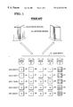
  • FIG. 1 A RAID level 4 system including five data and parity disk drives, DRIVE A through DRIVE E is illustrated in FIG. 1 .
  • An array controller not shown, coordinates the transfer of data between a host system and the array disk drives. The controller also calculates and checks parity information.
  • Data blocks A 0 through D 4 and parity blocks P 0 through P 4 illustrate the manner in which data and parity is stored on the five array drives. Data blocks A 0 through D 4 are also identified as blocks 0 through 19 .
  • RAID level 5 disk arrays are similar to RAID level 4 systems except that parity information, in addition to the data, is distributed across the N+1 disks in each group. Each one of the N+1 disks within the array includes some blocks for storing data and some blocks for storing parity information. Where parity information is stored is controlled by an algorithm implemented by the user. As in RAID level 4 systems, RAID level 5 writes typically require access to two disks; however, no longer does every write to the array require access to the same dedicated parity disk, as in RAID level 4 systems. This feature provides the opportunity to perform concurrent write operations.
  • a RAID level 5 system including five data and parity disk drives, DRIVE A through DRIVE E is illustrated in FIG. 3 .
  • An array controller not shown, coordinates the transfer of data between a host system and the array disk drives. The controller also calculates and checks parity information.
  • Data blocks A 0 through E 4 and parity blocks P 0 through P 4 illustrate the manner in which data and parity is stored on the five array drives. Data blocks A 0 through E 4 are also identified as blocks 0 through 19 .
  • PARITY P 1 (BLOCK 4 ) ⁇ (BLOCK 5 ) ⁇ (BLOCK 6 ) ⁇ (BLOCK 7 )
  • PARITY P 2 (BLOCK 8 ) ⁇ (BLOCK 9 ) ⁇ (BLOCK 10 ) ⁇ (BLOCK 11 )
  • PARITY P 3 (BLOCK 12 ) ⁇ (BLOCK 13 ) ⁇ (BLOCK 14 ) ⁇ (BLOCK 15 )
  • parity data can be calculated by performing a bit-wise exclusive-OR of corresponding portions of the data stored across the N data drives.
  • each parity bit is simply the exclusive-OR product of all the corresponding data bits from the data drives, new parity can be more easily determined from the old data and the old parity as well as the new data in accordance with the following equation:
  • RAID level 4 or 5 Although the parity calculation for RAID levels 4 or 5 shown in the above equation is much simpler than performing a bit-wise exclusive-OR of corresponding portions of the data stored across all of the data drives, a typical RAID level 4 or 5 write operation will require a minimum of two disk reads and two disk writes, in addition to the step of calculating the new parity information. This operation is referred to as a read-modify-write (RMW) operation. More than two disk reads and writes are required for data write operations involving more than one data block. Each individual disk read operation involves a seek and rotation to the appropriate disk track and sector to be read. The seek time for all disks is therefore the maximum of the seek times of each disk. A RAID level 4 or 5 system thus carries a significant write penalty when compared with a single disk storage device or with RAID level 1, 2 or 3 systems.
  • RMW read-modify-write
  • RAID level 4 and 5 disk array systems also provide for concurrent read and write operations. These storage arrangements provide an increased transfer bandwidth for multiple block read and write operations, e.g., four consecutive blocks can be read or written concurrently, and also improves the performance of small transfer operations by allowing blocks residing on separate disk drives to be accessed in parallel.
  • An improved method for generating and maintaining parity information in a RAID level 4 or 5 system which reduces or eliminates the write penalty resulting from the manner in which parity information is traditionally calculated and maintained is desired.
  • an improved disk array storage system comprised of N+2 disks wherein N disk drives are used to store data, and two additional disk drives are provided for the storage of parity information.
  • Data to be saved is divided into portions consisting of one or many blocks of data for storage among the disks.
  • Corresponding parity information comprised of first and second components, is written to the two dedicated parity disk drives.
  • a first parity generating mechanism is employed for calculating the first component of parity information to be written to the first parity disk drive
  • a second parity generating mechanism is employed for calculating the second component of parity information to be written to the second parity disk drive.
  • the two components of parity information are determined so that the exclusive-OR combination of the first and second components is equivalent to the exclusive-OR combination of the data stored across the remaining data disk drives.
  • the disk array storage system is shared by first and second processing nodes.
  • the first processing node processes a first group of processes performing updates on the data stored in the disk array storage system and includes the first parity generating mechanism for calculating the parity information to be maintained within the first parity disk drive.
  • the second processing node processes a second group of processes performing updates on the data stored in the disk array storage system and includes the second parity generating mechanism for calculating the parity information to be maintained within the second parity disk drive.
  • each one of the N+2 disk drives within the disk array storage system includes some blocks for storing data and some blocks for storing parity information.
  • the data and parity information is organized into multiple data groups within the array, each data group including a corresponding storage block from each disk drive.
  • N storage blocks within each data group are utilized to store data and two storage blocks within each data group are utilized to store first and second components of parity information. The location of the two storage blocks utilized to store the first and second components of parity information varies in the different data groups.
  • the first parity generating mechanism is employed for calculating the first components of parity information
  • the second parity generating mechanism is employed for calculating the second components of parity information.
  • the two components of parity information are determined so that the exclusive-OR combination of the first and second components is equivalent to the exclusive-OR combination of the data stored in the corresponding storage blocks across the remaining data disk drives.
  • FIG. 1 is a block diagram representation of a network including a shared RAID level 4 disk array storage system including four disk drives for the storage of data and an additional disk drive for the storage of parity information in accordance with the prior art.
  • FIG. 2 is a block diagram representation of a network including a shared RAID level 4 disk array storage system including four disk drives for the storage of data and two additional disk drives for the storage of parity information in accordance with the present invention.
  • FIG. 3 is a block diagram representation of a network including a shared RAID level 5 disk array storage system including five disk drives for the storage of data and parity information in accordance with the prior art.
  • FIG. 4 is a block diagram representation of a network including a shared RAID level 5 disk array storage system including six disk drives for the storage of data and parity information in accordance with the present invention.
  • FIG. 1 illustrates a RAID level 4 disk array storage system 101 utilized as a shared storage device accessible by two or more network servers 103 and 105 .
  • the RAID level 4 disk array storage system 101 includes four disk drives for the storage of data, identified as DRIVE A through DRIVE D, and an additional disk drive for the storage of parity information, identified as DRIVE E.
  • RAID level 4 disk array system 101 the data stored within RAID level 4 disk array system 101 is saved horizontally across the disk drives, i.e., successive data blocks are stored in successive disk drives. Data is written in blocks across disk drives DRIVE A through DRIVE D. Parity information is calculated by performing a bit-wise exclusive-OR of corresponding data blocks from disk drives DRIVE A through DRIVE D, or through a read-modify-write operation, then saved to a corresponding storage block on disk drive RIVE E.
  • the exemplary RAID level 4 array storage system of FIG. 1 provides storage for twenty data blocks of data organized into five data groups.
  • the data groups, identified as Data Group 0 through Data Group 4 each provide for the storage of four data blocks and one parity block.
  • the data blocks, numbered 0 through 19 are identified by reference numerals A 0 through D 4 . Parity blocks are identified by reference numerals P 0 through P 4 .
  • Parity information is calculated by performing a bit-wise exclusive-OR of corresponding data blocks stored across the four data drives, or through the read-modify-write (RMW) operation discussed above.
  • the single dedicated parity disk, DRIVE E, within the disk array storage system 101 can severely limit the performance of the storage system during concurrent write operations or data reconstruction activities since all write and data reconstruction operations require access to the single parity drive.
  • the improved disk array storage system illustrated in FIG. 2 greatly reduces the bottlenecks resulting from the use of a single dedicated parity disk in a RAID level 4 disk array storage system.
  • the system depicted in FIG. 2 is similar to that illustrated in FIG. 1 : a disk array storage system 101 utilized as a shared storage device accessible by two or more network servers 103 and 105 .
  • the disk array storage system 101 includes four disk drives for the storage of data, identified as DRIVE A through DRIVE D, but in contrast to the system of FIG. 1, the system depicted in FIG. 2 includes two disk drives for the storage of parity information, identified as DRIVE E and DRIVE F.
  • the disk array storage system illustrated in FIG. 2 provides storage for twenty data blocks of data organized into five data groups.
  • the data groups identified as Data Group 0 through Data Group 4 , each provide for the storage of four data blocks and two parity blocks.
  • the data blocks, numbered 0 through 19 are identified by reference numerals A 0 through D 4 .
  • Parity blocks are identified by reference numerals P 1 0 through P 1 4 and P 2 0 through P 2 4 .
  • Parity information saved to DRIVE E i.e., P 1 0 through P 1 4
  • parity information saved to DRIVE F i.e., P 2 0 through P 2 4
  • server 105 Each server is responsible for updating its component of parity information for specific data modifications. For example, server 103 , might be responsible for the parity generations associated with all data modifications originating with server 103 , while server 105 would be responsible for the parity generations associated with all data modifications originating with server 105 . Other methods for determining which server has responsibility for which data modifications and associated parity updates should be readily apparent to those skilled in the art. Each server determines parity through the read-modify-write operation as follows:
  • parity P 1 is the parity information component saved to DRIVE E
  • parity P 2 is the parity information component saved to DRIVE F
  • X represents the data group for which parity is calculated.
  • parity information component P 1 or P 2 individually will represent the parity value determined by performing a bit-wise exclusive-OR of corresponding data blocks stored across the four data drives.
  • the exclusive-OR operation utilized to calculate parity is both associative and commutative, the complete parity for the disk array storage system can be determined by exclusive-ORing corresponding parity blocks from DRIVE E and DRIVE F.
  • the complete parity for any data group X can be determined from the following equation:
  • FIG. 3 illustrates a RAID level 5 disk array storage system 201 utilized as a shared storage device accessible by two or more network servers 203 and 205 .
  • the RAID level 5 disk array storage system 201 includes five disk drives for the storage of data and parity information, identified as DRIVE A through DRIVE E.
  • the exemplary RAID level 5 array storage provides storage for twenty data blocks of data organized into five data groups.
  • the data groups identified as Data Group 0 through Data Group 4 , each provide for the storage of four data blocks and one parity block.
  • the data blocks, numbered 0 through 19 are identified by reference numerals A 0 through E 4 .
  • Parity blocks are identified by reference numerals P 0 through P 4 .
  • the location in which data and parity information are stored within the data groups varies from data group to data group. For example, in Data Group 0 data blocks A 0 , B 0 , C 0 and D 0 are stored on drives DRIVE A through DRIVE D and parity information P 0 is saved on drive DRIVE E. However in Data Group 1 data blocks A 1 , B 1 , C 1 and E 1 are stored on drives DRIVE A, DRIVE B, DRIVE C, and DRIVE E, respectively, and parity information P 1 is saved on drive DRIVE D. Within each data group, parity information is calculated by performing a bit-wise exclusive-OR of corresponding data blocks, or through the read-modify-write (RMW) operation.
  • RMW read-modify-write
  • FIG. 4 illustrates an improvement to the RAID level 5 disk array system shown in FIG. 3 .
  • the system illustrated in FIG. 4 differs from the system shown in FIG. 3 by including six disk drives for the storage of data and parity information, identified as DRIVE A through DRIVE F, rather than five disk drives, as shown in FIG. 3 .
  • the disk array storage system illustrated in FIG. 4 provides storage for twenty data blocks of data organized into five data groups.
  • the data groups identified as Data Group 0 through Data Group 4 , each provide for the storage of four data blocks and two parity blocks.
  • the data blocks, numbered 0 through 19 are identified by reference numerals A 0 through F 4 .
  • Parity blocks are identified by reference numerals P 1 0 through P 1 4 and P 2 0 through P 2 4 .
  • the location in which data and parity information are stored within the data groups varies from data group to data group.
  • data groups A 0 , B 0 , C 0 and D 0 are stored on drives DRIVE A through DRIVE D and parity information components P 1 0 and P 2 0 are saved on drives DRIVE E and DRIVE F.
  • data Group 2 data blocks A 1 , B 1 , C 1 and F 1 are stored on drives DRIVE A, DRIVE B, DRIVE C, and DRIVE F, respectively, while parity information components P 1 1 and P 2 1 are saved on drives DRIVE D and DRIVE E.
  • Parity information components P 1 0 through P 1 4 are calculated by server 203
  • parity information components P 2 0 through P 2 4 is calculated by server 205 .
  • Each server is responsible for updating its piece of parity information for specific data modifications. For example, server 203 , might be responsible for the parity generations associated with all data modifications originating with server 203 , while server 205 would be responsible for the parity generations associated with all data modifications originating with server 205 . Other methods for determining which server has responsibility for which data modifications and associated parity updates should be readily apparent to those skilled in the art.
  • Each server determines parity through the read-modify-write operation as follows:
  • parity P 1 is the parity information component determined by server 203
  • parity P 2 is the parity information component calculated by server 205
  • X represents the data group for which parity is calculated.
  • the complete parity for the disk array storage system can be determined by exclusive-ORing corresponding parity blocks within the data groups.
  • the complete parity for any data group can be determined from the following equation:

Abstract

An improved disk array storage system shared by first and second processing nodes is comprised of N+2 disks wherein N disk drives are used to store data, and two additional disk drives are provided for the storage of parity information. Data to be saved is divided into portions consisting of one or many blocks of data for storage among the disks. Corresponding parity information, comprised of first and second components, is written to the two dedicated parity disk drives. The first processing node determines the first component of parity information to be written to the first parity disk drive, and a second processing node determines the second component of parity information to be written to the second parity disk drive. The two components of parity information are determined so that the exclusive-OR combination of the first and second components is equivalent to the exclusive-OR combination of the data stored across the remaining data disk drives.

Description

The present invention relates to disk array storage devices for computer systems and, more particularly, to an improved method for generating parity information in a disk array storage system.
BACKGROUND OF THE INVENTION
A disk array or RAID (Redundant Array of Inexpensive Disks) storage system comprises two or more hard disk drives, such as the commodity 3½ inch disk drives currently used in personal computers and workstations, functioning together as a single storage system. Although disk array products have been available for several years, significant improvements in the reliability and performance of small disk drives and a decline in the cost of such drives, together with end user requirements for increased system storage capacity, faster access speeds, improved reliability, and greater resistance to errors have resulted in enhanced interest in RAID systems.
Several disk array design alternatives were first described in an article titled “A Case for Redundant Arrays of Inexpensive Disks (RAID)” by David A. Patterson, Garth Gibson and Randy H. Katz; University of California Report No. UCB/CSD 87/391, December 1987. This article discusses disk arrays and the improvements in performance, reliability, power consumption and scalability that disk arrays provide in comparison to single large magnetic disks. Five disk array arrangements, referred to as RAID levels, are described. The simplest array, a RAID level 1 system, comprises one or more disks for storing data and an equal number of additional “mirror” disks for storing copies of the information written to the data disks. The remaining RAID levels, identified as RAID level 2, 3, 4 and 5 systems, segment the data into portions for storage across several data disks. One or more additional disks are utilized to store error check or parity information.
In 1993, these RAID levels were formalized in the first edition of the RAIDBook, published by the RAID Advisory Board, an association of manufacturers and consumers of disk array storage systems. In addition to the five RAID levels described by Patterson et al., the RAID Advisory Board now recognizes four additional RAID levels, including RAID level 0, RAID level 6, RAID level 10 and RAID level 53.
In order to coordinate the operation of the multitude of disk or tape drives within an array to perform read and write functions, parity generation and checking, and data restoration and reconstruction, complex storage management techniques are required. Array operation can be managed through software routines executed by the host computer system, i.e., a software array architecture, or by a dedicated hardware controller constructed to control array operations.
A RAID level 4 disk array is comprised of N+1 disks wherein N disks are used to store data, and the additional disk is utilized to store parity information. Data to be saved is divided into portions consisting of one or many blocks of data for storage among the disks. The corresponding parity information, which can be calculated by performing a bit-wise exclusive-OR of corresponding portions of the data stored across the N data drives, is written to the dedicated parity disk. The parity disk is used to reconstruct information in the event of a disk failure. Writes typically require access to two disks, i.e., one of the N data disks and the parity disk, as will be discussed in greater detail below. Read operations typically need only access a single one of the N data disks, unless the data to be read exceeds the block length stored on each disk.
A RAID level 4 system including five data and parity disk drives, DRIVE A through DRIVE E is illustrated in FIG. 1. An array controller, not shown, coordinates the transfer of data between a host system and the array disk drives. The controller also calculates and checks parity information. Data blocks A0 through D4 and parity blocks P0 through P4 illustrate the manner in which data and parity is stored on the five array drives. Data blocks A0 through D4 are also identified as blocks 0 through 19.
RAID level 5 disk arrays are similar to RAID level 4 systems except that parity information, in addition to the data, is distributed across the N+1 disks in each group. Each one of the N+1 disks within the array includes some blocks for storing data and some blocks for storing parity information. Where parity information is stored is controlled by an algorithm implemented by the user. As in RAID level 4 systems, RAID level 5 writes typically require access to two disks; however, no longer does every write to the array require access to the same dedicated parity disk, as in RAID level 4 systems. This feature provides the opportunity to perform concurrent write operations.
A RAID level 5 system including five data and parity disk drives, DRIVE A through DRIVE E is illustrated in FIG. 3. An array controller, not shown, coordinates the transfer of data between a host system and the array disk drives. The controller also calculates and checks parity information. Data blocks A0 through E4 and parity blocks P0 through P4 illustrate the manner in which data and parity is stored on the five array drives. Data blocks A0 through E4 are also identified as blocks 0 through 19.
The relationship between the parity and data blocks in both the RAID level 4 and 5 systems described above, and illustrated in FIGS. 1 and 3, respectively, is as follows:
PARITY P0=(BLOCK 0)⊕(BLOCK 1)⊕(BLOCK 2)⊕(BLOCK 3)
PARITY P1=(BLOCK 4)⊕(BLOCK 5)⊕(BLOCK 6)⊕(BLOCK 7)
PARITY P2=(BLOCK 8)⊕(BLOCK 9)⊕(BLOCK 10)⊕(BLOCK 11)
PARITY P3=(BLOCK 12)⊕(BLOCK 13)⊕(BLOCK 14)⊕(BLOCK 15)
As shown above, parity data can be calculated by performing a bit-wise exclusive-OR of corresponding portions of the data stored across the N data drives. However, because each parity bit is simply the exclusive-OR product of all the corresponding data bits from the data drives, new parity can be more easily determined from the old data and the old parity as well as the new data in accordance with the following equation:
new parity=old data⊕new data⊕old parity.
Although the parity calculation for RAID levels 4 or 5 shown in the above equation is much simpler than performing a bit-wise exclusive-OR of corresponding portions of the data stored across all of the data drives, a typical RAID level 4 or 5 write operation will require a minimum of two disk reads and two disk writes, in addition to the step of calculating the new parity information. This operation is referred to as a read-modify-write (RMW) operation. More than two disk reads and writes are required for data write operations involving more than one data block. Each individual disk read operation involves a seek and rotation to the appropriate disk track and sector to be read. The seek time for all disks is therefore the maximum of the seek times of each disk. A RAID level 4 or 5 system thus carries a significant write penalty when compared with a single disk storage device or with RAID level 1, 2 or 3 systems.
In addition to the advantages described above for RAID storage systems, i.e., increased system storage capacity, faster access speeds, improved reliability, RAID level 4 and 5 disk array systems also provide for concurrent read and write operations. These storage arrangements provide an increased transfer bandwidth for multiple block read and write operations, e.g., four consecutive blocks can be read or written concurrently, and also improves the performance of small transfer operations by allowing blocks residing on separate disk drives to be accessed in parallel.
An improved method for generating and maintaining parity information in a RAID level 4 or 5 system which reduces or eliminates the write penalty resulting from the manner in which parity information is traditionally calculated and maintained is desired.
OBJECTS OF THE INVENTION
It is therefore an object of the present invention to provide a new and useful method for updating data and parity information within a disk array.
It is another object of the present invention to provide such a method which optimally executes read-modify-write procedures within RAID level 4 and 5 disk arrays.
It is yet another object of the present invention to provide a new and useful method for improving the efficiency of disk drive utilization within a disk array.
It is still a further object of the present invention to provide a new and useful method for minimizing I/O service times and I/O queue waiting times for individual drives within a disk array.
SUMMARY OF THE INVENTION
There is provided, in accordance with the present invention, an improved disk array storage system comprised of N+2 disks wherein N disk drives are used to store data, and two additional disk drives are provided for the storage of parity information. Data to be saved is divided into portions consisting of one or many blocks of data for storage among the disks. Corresponding parity information, comprised of first and second components, is written to the two dedicated parity disk drives. A first parity generating mechanism is employed for calculating the first component of parity information to be written to the first parity disk drive, and a second parity generating mechanism is employed for calculating the second component of parity information to be written to the second parity disk drive. The two components of parity information are determined so that the exclusive-OR combination of the first and second components is equivalent to the exclusive-OR combination of the data stored across the remaining data disk drives.
In the described system, the disk array storage system is shared by first and second processing nodes. The first processing node processes a first group of processes performing updates on the data stored in the disk array storage system and includes the first parity generating mechanism for calculating the parity information to be maintained within the first parity disk drive. Similarly, the second processing node processes a second group of processes performing updates on the data stored in the disk array storage system and includes the second parity generating mechanism for calculating the parity information to be maintained within the second parity disk drive.
In another embodiment of the invention, each one of the N+2 disk drives within the disk array storage system includes some blocks for storing data and some blocks for storing parity information. The data and parity information is organized into multiple data groups within the array, each data group including a corresponding storage block from each disk drive. N storage blocks within each data group are utilized to store data and two storage blocks within each data group are utilized to store first and second components of parity information. The location of the two storage blocks utilized to store the first and second components of parity information varies in the different data groups.
The first parity generating mechanism is employed for calculating the first components of parity information, and the second parity generating mechanism is employed for calculating the second components of parity information. Within each data group, the two components of parity information are determined so that the exclusive-OR combination of the first and second components is equivalent to the exclusive-OR combination of the data stored in the corresponding storage blocks across the remaining data disk drives.
The above objects and other objects, features, and advantages of the present invention will become apparent from the following detailed specification when read in conjunction with the accompanying drawings in which applicable reference numerals have been carried forward.
BRIEF DESCRIPTION OF THE DRAWINGS
FIG. 1 is a block diagram representation of a network including a shared RAID level 4 disk array storage system including four disk drives for the storage of data and an additional disk drive for the storage of parity information in accordance with the prior art.
FIG. 2 is a block diagram representation of a network including a shared RAID level 4 disk array storage system including four disk drives for the storage of data and two additional disk drives for the storage of parity information in accordance with the present invention.
FIG. 3 is a block diagram representation of a network including a shared RAID level 5 disk array storage system including five disk drives for the storage of data and parity information in accordance with the prior art.
FIG. 4 is a block diagram representation of a network including a shared RAID level 5 disk array storage system including six disk drives for the storage of data and parity information in accordance with the present invention.
DETAILED DESCRIPTION OF THE PREFERRED EMBODIMENT RAID Level 4 Disk Array Implementation
FIG. 1 illustrates a RAID level 4 disk array storage system 101 utilized as a shared storage device accessible by two or more network servers 103 and 105. The RAID level 4 disk array storage system 101 includes four disk drives for the storage of data, identified as DRIVE A through DRIVE D, and an additional disk drive for the storage of parity information, identified as DRIVE E.
As shown in FIG. 1, the data stored within RAID level 4 disk array system 101 is saved horizontally across the disk drives, i.e., successive data blocks are stored in successive disk drives. Data is written in blocks across disk drives DRIVE A through DRIVE D. Parity information is calculated by performing a bit-wise exclusive-OR of corresponding data blocks from disk drives DRIVE A through DRIVE D, or through a read-modify-write operation, then saved to a corresponding storage block on disk drive RIVE E. The exemplary RAID level 4 array storage system of FIG. 1 provides storage for twenty data blocks of data organized into five data groups. The data groups, identified as Data Group 0 through Data Group 4, each provide for the storage of four data blocks and one parity block. The data blocks, numbered 0 through 19, are identified by reference numerals A0 through D4. Parity blocks are identified by reference numerals P0 through P4.
Parity information is calculated by performing a bit-wise exclusive-OR of corresponding data blocks stored across the four data drives, or through the read-modify-write (RMW) operation discussed above.
Although only five data groups and twenty data blocks are illustrated, it should be understood that an array storage system utilizing current magnetic disk drives, such as the Western Digital Corporation WD Caviar AC36400 disk drive described above, is capable of storing millions of data blocks.
The single dedicated parity disk, DRIVE E, within the disk array storage system 101 can severely limit the performance of the storage system during concurrent write operations or data reconstruction activities since all write and data reconstruction operations require access to the single parity drive. The improved disk array storage system illustrated in FIG. 2 greatly reduces the bottlenecks resulting from the use of a single dedicated parity disk in a RAID level 4 disk array storage system.
The system depicted in FIG. 2 is similar to that illustrated in FIG. 1: a disk array storage system 101 utilized as a shared storage device accessible by two or more network servers 103 and 105. The disk array storage system 101 includes four disk drives for the storage of data, identified as DRIVE A through DRIVE D, but in contrast to the system of FIG. 1, the system depicted in FIG. 2 includes two disk drives for the storage of parity information, identified as DRIVE E and DRIVE F.
The disk array storage system illustrated in FIG. 2 provides storage for twenty data blocks of data organized into five data groups. The data groups, identified as Data Group 0 through Data Group 4, each provide for the storage of four data blocks and two parity blocks. The data blocks, numbered 0 through 19, are identified by reference numerals A0 through D4. Parity blocks are identified by reference numerals P 1 0 through P 1 4 and P 2 0 through P 2 4.
Parity information saved to DRIVE E, i.e., P 1 0 through P 1 4, is calculated by server 103, while parity information saved to DRIVE F, i.e., P 2 0 through P 2 4, is calculated by server 105. Each server is responsible for updating its component of parity information for specific data modifications. For example, server 103, might be responsible for the parity generations associated with all data modifications originating with server 103, while server 105 would be responsible for the parity generations associated with all data modifications originating with server 105. Other methods for determining which server has responsibility for which data modifications and associated parity updates should be readily apparent to those skilled in the art. Each server determines parity through the read-modify-write operation as follows:
new parity P1X=old data⊕new data⊕old parity P1X; and
new parity P2X=old data⊕new data⊕old parity P2X;
where parity P1 is the parity information component saved to DRIVE E, parity P2 is the parity information component saved to DRIVE F, and X represents the data group for which parity is calculated.
Initially, all data disks and both parity disks will contain all zeros data. Alternatively, the array may preloaded with data, in which case parity will need to be calculated and written to one of the two parity disks, the other disk containing all zeros. Over time, however, as each server writes new data and parity to the disk array storage system 101, neither parity information component P1 or P2 individually will represent the parity value determined by performing a bit-wise exclusive-OR of corresponding data blocks stored across the four data drives. However, because the exclusive-OR operation utilized to calculate parity is both associative and commutative, the complete parity for the disk array storage system can be determined by exclusive-ORing corresponding parity blocks from DRIVE E and DRIVE F. The complete parity for any data group X can be determined from the following equation:
parity P=P1X⊕P2X.
RAID Level 5 Disk Array Implementation
FIG. 3 illustrates a RAID level 5 disk array storage system 201 utilized as a shared storage device accessible by two or more network servers 203 and 205. The RAID level 5 disk array storage system 201 includes five disk drives for the storage of data and parity information, identified as DRIVE A through DRIVE E.
As shown in FIG. 3, the exemplary RAID level 5 array storage provides storage for twenty data blocks of data organized into five data groups. The data groups, identified as Data Group 0 through Data Group 4, each provide for the storage of four data blocks and one parity block. The data blocks, numbered 0 through 19, are identified by reference numerals A0 through E4. Parity blocks are identified by reference numerals P0 through P4.
The location in which data and parity information are stored within the data groups varies from data group to data group. For example, in Data Group 0 data blocks A0, B0, C0 and D0 are stored on drives DRIVE A through DRIVE D and parity information P0 is saved on drive DRIVE E. However in Data Group 1 data blocks A1, B1, C1 and E1 are stored on drives DRIVE A, DRIVE B, DRIVE C, and DRIVE E, respectively, and parity information P1 is saved on drive DRIVE D. Within each data group, parity information is calculated by performing a bit-wise exclusive-OR of corresponding data blocks, or through the read-modify-write (RMW) operation. By varying the location of the parity information and distributing the parity information equally across the disk drives within the array, the primary shortcoming of the RAID level 4 disk array design, i.e., contention for access to the single dedicated parity disk, is greatly reduced.
Although only five data groups and twenty data blocks are illustrated, it should be understood that an array storage system utilizing current magnetic disk drives, such as the Western Digital Corporation WD Caviar AC36400 disk drive described above, is capable of storing millions of data blocks.
FIG. 4 illustrates an improvement to the RAID level 5 disk array system shown in FIG. 3. The system illustrated in FIG. 4 differs from the system shown in FIG. 3 by including six disk drives for the storage of data and parity information, identified as DRIVE A through DRIVE F, rather than five disk drives, as shown in FIG. 3.
The disk array storage system illustrated in FIG. 4 provides storage for twenty data blocks of data organized into five data groups. The data groups, identified as Data Group 0 through Data Group 4, each provide for the storage of four data blocks and two parity blocks. The data blocks, numbered 0 through 19, are identified by reference numerals A0 through F4. Parity blocks are identified by reference numerals P 1 0 through P 1 4 and P 2 0 through P 2 4.
As in the system shown in FIG. 3, the location in which data and parity information are stored within the data groups varies from data group to data group. For example, in Data Group 0 data blocks A0, B0, C0 and D0 are stored on drives DRIVE A through DRIVE D and parity information components P 1 0 and P 2 0 are saved on drives DRIVE E and DRIVE F. However in Data Group 2 data blocks A1, B1, C1 and F1 are stored on drives DRIVE A, DRIVE B, DRIVE C, and DRIVE F, respectively, while parity information components P 1 1 and P 2 1 are saved on drives DRIVE D and DRIVE E.
Parity information components P 1 0 through P 1 4, are calculated by server 203, while parity information components P 2 0 through P 2 4, is calculated by server 205. Each server is responsible for updating its piece of parity information for specific data modifications. For example, server 203, might be responsible for the parity generations associated with all data modifications originating with server 203, while server 205 would be responsible for the parity generations associated with all data modifications originating with server 205. Other methods for determining which server has responsibility for which data modifications and associated parity updates should be readily apparent to those skilled in the art. Each server determines parity through the read-modify-write operation as follows:
new parity P1X=old data⊕new data⊕old parity P1X; and
new parity P2X=old data⊕new data⊕old parity P2X;
where parity P1 is the parity information component determined by server 203, parity P2 is the parity information component calculated by server 205, and X represents the data group for which parity is calculated.
Initially, all disks within the array will contain all zeros. Alternatively, the array may preloaded with data, in which case parity will need to be calculated and written to one of the two groups of parity data blocks, i.e., P1X or P2X, the other group of data blocks containing all zeros. Over time, however, as each server writes new data and parity to the disk array storage system 101, neither parity information component P1 or P2 individually will represent the parity value determined by performing a bit-wise exclusive-OR of corresponding data blocks stored within a data group. However, because the exclusive-OR operation utilized to calculate parity is both associative and commutative, the complete parity for the disk array storage system can be determined by exclusive-ORing corresponding parity blocks within the data groups. The complete parity for any data group can be determined from the following equation:
parity P=P1X⊕P2X.
SUMMARY
It can thus be seen that there has been provided by the present invention a new and useful method for calculating and storing data and parity information within a RAID level 4 or 5 disk array storage system. The above-described method extends the parity generating mechanism within the array to encompass multiple parity pieces rather than the single piece currently in use. Multiple parity pieces permits each piece to be assigned to a given parity generator/writer. This organization reduces the coordination required to maintain parity and increases array and system performance by reducing overhead and lock contention.
Those skilled in the art will recognize that the invention is not limited to the specific embodiments described above and that numerous modifications and changes are possible without departing from the scope of the present invention. For example, although the above detailed description describes disk array systems including a total of six disk drives for the storage of data and parity information, a greater number of drives may be utilized to store data and parity within the disk array. In such a system more than two additional drives may be provided to store components of parity information, with a corresponding number of processing nodes responsible for maintaining parity information. Also, in the RAID 5 disk array implementation described above, the manner in which parity information storage blocks is distributed throughout the multiple disk drives may differ from that shown.
These and other variations, changes, substitution and equivalents will be readily apparent to those skilled in the art without departing from the spirit and scope of the present invention. Accordingly, it is intended that the invention to be secured by Letters Patent be limited only by the scope of the appended claims.

Claims (22)

What is claimed is:
1. A disk array storage system wherein data and related parity information are stored in corresponding storage blocks across a plurality of disk drives, said disk array storage system comprising:
a first disk drive including a storage block for the non-volatile storage of a first component of parity information;
a second disk drive including a storage block for the non-volatile storage of a second component of parity information;
at least two disk drives including corresponding storage blocks for the storage of data;
a first parity generating mechanism for calculating said first component of parity information stored on said first disk drive; and
a second parity generating mechanism for calculating said second component of parity information stored on said second disk drive;
wherein the exclusive-OR combination of said first component of parity information with said second component of parity information is equivalent to the exclusive-OR combination of the data stored within the corresponding storage blocks of said at least two disk drives.
2. The disk array storage system in accordance with claim 1, wherein:
said disk array storage system is shared by a first processing node and a second processing node;
said first parity generating mechanism for calculating said first component of parity information is included in said first processing node; and
said second parity generating mechanism for calculating said second component of parity information is included in said second processing node.
3. The disk array storage system in accordance with claim 2, wherein:
said first processing node processes a first group of processes performing updates on said data stored in said at least two disk drives including corresponding storage blocks for the storage of data; and
said second processing node processes a second group of processes performing updates on said data stored in said at least two disk drives including corresponding storage blocks for the storage of data.
4. The disk array storage system in accordance with claim 2, wherein:
said first processing node utilizes a read-modify-write procedure to update said data and said first component of parity information; and
said second processing node utilizes a read-modify-write procedure to update said data and said second component of parity information.
5. A computer system comprising:
a first processing node;
a second processing node; and
a disk array storage system shared by said first and second servers, said disk array storage system including:
a first disk drive including a storage block for the non-volatile storage of a first component of parity information;
a second disk drive including a storage block for the non-volatile storage of a second component of parity information;
at least two disk drives including corresponding storage blocks for the storage of data;
a first parity generating mechanism included in said first processing node for calculating said first component of parity information stored on said first disk drive; and
a second parity generating mechanism included in said second processing node for calculating said second component of parity information stored on said second disk drive;
wherein the exclusive-OR combination of said first component of parity information with said second component of parity information is equivalent to the exclusive-OR combination of the data stored within the corresponding storage blocks of said at least two disk drives.
6. The computer system in accordance with claim 5, wherein:
said first processing node processes a first group of processes performing updates on said data stored in said at least two disk drives including corresponding storage blocks for the storage of data; and
said second processing node processes a second group of processes performing updates on said data stored in said at least two disk drives including corresponding storage blocks for the storage of data.
7. In a disk array storage system wherein data is stored in corresponding storage blocks across a plurality of disk drives, a method for calculating and storing parity information, said method comprising the steps of:
providing a first disk drive for the non-volatile storage of parity information, said first disk drive including a storage block corresponding to the storage blocks included in said plurality of disk drives;
providing a first parity generation mechanism for calculating a first component of parity information,
storing said first component of parity information in said storage block on said first disk drive;
providing a second disk drive for the non-volatile storage parity information; said second disk drive including a storage block corresponding to the storage blocks included in said plurality of disk drives and said first disk drive; and
providing a second parity generation mechanism for calculating a second component of parity information, and
storing said second component of parity information in said storage block on said second disk drive;
wherein the exclusive-OR combination of said first component of parity information with said second component of parity information is equivalent to the exclusive-OR combination of the data stored within the corresponding storage blocks of said at least two disk drives.
8. The method for calculating and storing parity information in accordance with claim 7, further comprising the steps of:
updating said data and said first component of parity information in response to one of a first group of processes; and
updating said data and said second component of parity information in response to one of a second group of processes.
9. The method for calculating and storing parity information in accordance with claim 8, wherein:
said disk array storage system is shared by a first processing node and a second processing node;
said step of updating said data and said first component of parity information in response to one of a first group of processes is performed by said first processing node; and
said step of updating said data and said second component of parity information in response to one of a second group of processes is performed by said second processing node.
10. The method for calculating and storing parity information in accordance with claim 8, wherein:
said step of updating said data and said first component of parity information in response to one of a first group of processes includes the execution of a read-modify-write procedure; and
said step of updating said data and said second component of parity information in response to one of a second group of processes includes the execution of a read-modify-write procedure.
11. A disk array storage system comprising:
a plurality of disk drives for the storage of data and parity information, said data and parity information being stored in multiple data groups within a plurality of disk drives, each data group containing a corresponding storage block from each disk drive within said plurality of disk drives;
each data group including a first storage block for the non-volatile storage of a first component of parity information, a second storage block for the non-volatile storage of a second component of parity information, and at least two storage blocks for the storage of data;
a first parity generating mechanism for determining said first component of parity information; and
a second parity generating mechanism for determining said second component of parity information stored;
wherein the exclusive-OR combination of said first component of parity information with said second component of parity information is equivalent to the exclusive-OR combination of the data stored within the corresponding storage blocks of said at least two disk drives.
12. The disk array storage system in accordance with claim 11, wherein:
said disk array storage system is shared by a first processing node and a second processing node;
said first parity generating mechanism for calculating said first component of parity information is included in said first processing node; and
said second parity generating mechanism for calculating said second component of parity information is included in said second processing node.
13. The disk array storage system in accordance with claim 12, wherein:
said first processing node processes a first group of processes performing updates on said data stored in said at least two storage blocks for the storage of data; and
said second processing node processes a second group of processes performing updates on said data stored in said at least two disk drives including corresponding storage blocks for the storage of data.
14. The disk array storage system in accordance with claim 13, wherein:
said first processing node utilizes a read-modify-write procedure to update said data and said first component of parity information; and
said second processing node utilizes a read-modify-write procedure to update said data and said second component of parity information.
15. The disk array storage system in accordance with claim 11, wherein:
the disk drive on which said first storage block resides and the disk drive on which said second storage resides varies in the multiple data groups.
16. The disk array storage system in accordance with claim 15, wherein:
said disk array storage system is shared by a first processing node and a second processing node;
said first parity generating mechanism for calculating said first component of parity information is included in said first processing node; and
said second parity generating mechanism for calculating said second component of parity information is included in said second processing node.
17. The disk array storage system in accordance with claim 16, wherein:
said first processing node processes a first group of processes performing updates on said data stored in said at least two storage blocks for the storage of data; and
said second processing node processes a second group of processes performing updates on said data stored in said at least two disk drives including corresponding storage blocks for the storage of data.
18. The disk array storage system in accordance with claim 17, wherein:
said first processing node utilizes a read-modify-write procedure to update said data and said first component of parity information; and
said second processing node utilizes a read-modify-write procedure to update said data and said second component of parity information.
19. A method for storing data and parity information in a disk array, said method comprising the steps of:
providing a plurality of disk drives for the storage of data and parity information, said data and parity information being stored in multiple data groups within said plurality of disk drives, each data group containing a corresponding storage block from each disk drive within said plurality of disk drives, each data group including a first storage block for the nonvolatile storage of a first component of parity information, a second storage block for the non-volatile storage of a second component of parity information, and at least two storage blocks for the storage of data;
providing a first parity generation mechanism for calculating said first component of parity information;
providing a second parity generation mechanism for calculating said second component of parity information;
varying the location of said first storage block and said second storage among the plurality of disk drives in different ones of said multiple data groups; and
within each data group:
determining said first component of parity information,
storing said first component of parity information in said first storage block;
determining said second component of parity information, and
storing said second component of parity information in said second storage block;
wherein the exclusive-OR combination of said first component of parity information with said second component of parity information is equivalent to the exclusive-OR combination of the data stored within the corresponding storage blocks of said at least two disk drives.
20. The method for calculating and storing parity information in accordance with claim 19, further comprising the steps of:
updating said data and said first component of parity information within a data group in response to one of a first group of processes; and
updating said data and said second component of parity information within a data group in response to one of a second group of processes.
21. The method for calculating and storing parity information in accordance with claim 20, wherein:
said disk array storage system is shared by a first processing node and a second processing node;
said step of updating said data and said first component of parity information within a data group in response to one of a first group of processes is performed by said first processing node; and
said step of updating said data and said second component of parity information within a data group in response to one of a second group of processes is performed by said second processing node.
22. The method for calculating and storing parity information in accordance with claim 20, wherein:
said step of updating said data and said first component of parity information within a data group in response to one of a first group of processes includes the execution of a read-modify-write procedure; and
said step of updating said data and said second component of parity information within a data group in response to one of a second group of processes includes the execution of a read-modify-write procedure.
US09/118,678 1998-07-17 1998-07-17 Method for storing parity information in a disk array storage system Expired - Lifetime US6223323B1 (en)

Priority Applications (1)

Application Number Priority Date Filing Date Title
US09/118,678 US6223323B1 (en) 1998-07-17 1998-07-17 Method for storing parity information in a disk array storage system

Applications Claiming Priority (1)

Application Number Priority Date Filing Date Title
US09/118,678 US6223323B1 (en) 1998-07-17 1998-07-17 Method for storing parity information in a disk array storage system

Publications (1)

Publication Number Publication Date
US6223323B1 true US6223323B1 (en) 2001-04-24

Family

ID=22380087

Family Applications (1)

Application Number Title Priority Date Filing Date
US09/118,678 Expired - Lifetime US6223323B1 (en) 1998-07-17 1998-07-17 Method for storing parity information in a disk array storage system

Country Status (1)

Country Link
US (1) US6223323B1 (en)

Cited By (21)

* Cited by examiner, † Cited by third party
Publication number Priority date Publication date Assignee Title
US6351838B1 (en) * 1999-03-12 2002-02-26 Aurora Communications, Inc Multidimensional parity protection system
US6353895B1 (en) * 1998-02-19 2002-03-05 Adaptec, Inc. RAID architecture with two-drive fault tolerance
US6532548B1 (en) * 1999-09-21 2003-03-11 Storage Technology Corporation System and method for handling temporary errors on a redundant array of independent tapes (RAIT)
US20030105912A1 (en) * 2001-11-30 2003-06-05 Noren Gregory T. Space efficient backup technique in a storage system
US6769088B1 (en) * 1999-06-30 2004-07-27 Maxtor Corporation Sector-coding technique for reduced read-after-write operations
DE10350590A1 (en) * 2003-10-30 2005-06-16 Ruprecht-Karls-Universität Heidelberg Method and device for saving data in several independent read-write memories
US20050283652A1 (en) * 2004-02-06 2005-12-22 Hon Hai Precision Industry Co., Ltd. Fault tolerance system and method for one or two failed disks in a disk array
US20070028043A1 (en) * 2005-07-29 2007-02-01 Ray Jantz Method for creating a large-scale storage array system out of multiple mid-range storage arrays
US20070089045A1 (en) * 2001-12-28 2007-04-19 Corbett Peter F Triple parity technique for enabling efficient recovery from triple failures in a storage array
CN1323346C (en) * 2004-04-14 2007-06-27 株式会社日立制作所 Storage system
CN100419700C (en) * 2004-02-11 2008-09-17 鸿富锦精密工业(深圳)有限公司 Disk faulttolerant system and method
US7627715B1 (en) * 2001-11-13 2009-12-01 Netapp, Inc. Concentrated parity technique for handling double failures and enabling storage of more than one parity block per stripe on a storage device of a storage array
US20110208996A1 (en) * 2010-02-22 2011-08-25 International Business Machines Corporation Read-other protocol for maintaining parity coherency in a write-back distributed redundancy data storage system
US20110208994A1 (en) * 2010-02-22 2011-08-25 International Business Machines Corporation Rebuilding lost data in a distributed redundancy data storage system
US20110208995A1 (en) * 2010-02-22 2011-08-25 International Business Machines Corporation Read-modify-write protocol for maintaining parity coherency in a write-back distributed redundancy data storage system
US20110208912A1 (en) * 2010-02-22 2011-08-25 International Business Machines Corporation Full-stripe-write protocol for maintaining parity coherency in a write-back distributed redundancy data storage system
US20120079349A1 (en) * 2010-09-24 2012-03-29 Arkady Bramnik Method and apparatus for multi-bit upset protection
US8402346B2 (en) 2001-12-28 2013-03-19 Netapp, Inc. N-way parity technique for enabling recovery from up to N storage device failures
US20150162102A1 (en) * 2013-12-06 2015-06-11 Feiyue Xu Method and System for Reliable Big Capacity Storage System Protected by Triple Protection
US20170091022A1 (en) * 2015-09-25 2017-03-30 Jawad B. Khan Techniques to Recover Data Using Exclusive OR (XOR) Parity Information
US10133633B2 (en) * 2015-06-04 2018-11-20 Huawei Technologies Co., Ltd. Data storage method, data recovery method, related apparatus, and system

Citations (5)

* Cited by examiner, † Cited by third party
Publication number Priority date Publication date Assignee Title
US5388108A (en) * 1992-10-23 1995-02-07 Ncr Corporation Delayed initiation of read-modify-write parity operations in a raid level 5 disk array
US5630007A (en) * 1995-03-30 1997-05-13 Mitsubishi Denki Kabushiki Kaisha Client-server system with parity storage
US5856989A (en) * 1996-08-13 1999-01-05 Hewlett-Packard Company Method and apparatus for parity block generation
US5867640A (en) * 1993-06-01 1999-02-02 Mti Technology Corp. Apparatus and method for improving write-throughput in a redundant array of mass storage devices
US5892780A (en) * 1995-01-26 1999-04-06 International Business Machines Corporation Data storage system and parity generation method for data storage system

Patent Citations (5)

* Cited by examiner, † Cited by third party
Publication number Priority date Publication date Assignee Title
US5388108A (en) * 1992-10-23 1995-02-07 Ncr Corporation Delayed initiation of read-modify-write parity operations in a raid level 5 disk array
US5867640A (en) * 1993-06-01 1999-02-02 Mti Technology Corp. Apparatus and method for improving write-throughput in a redundant array of mass storage devices
US5892780A (en) * 1995-01-26 1999-04-06 International Business Machines Corporation Data storage system and parity generation method for data storage system
US5630007A (en) * 1995-03-30 1997-05-13 Mitsubishi Denki Kabushiki Kaisha Client-server system with parity storage
US5856989A (en) * 1996-08-13 1999-01-05 Hewlett-Packard Company Method and apparatus for parity block generation

Cited By (38)

* Cited by examiner, † Cited by third party
Publication number Priority date Publication date Assignee Title
US6353895B1 (en) * 1998-02-19 2002-03-05 Adaptec, Inc. RAID architecture with two-drive fault tolerance
US6351838B1 (en) * 1999-03-12 2002-02-26 Aurora Communications, Inc Multidimensional parity protection system
US6769088B1 (en) * 1999-06-30 2004-07-27 Maxtor Corporation Sector-coding technique for reduced read-after-write operations
US6532548B1 (en) * 1999-09-21 2003-03-11 Storage Technology Corporation System and method for handling temporary errors on a redundant array of independent tapes (RAIT)
US8468304B1 (en) 2001-11-13 2013-06-18 Netapp, Inc. Concentrated parity technique for handling double failures and enabling storage of more than one parity block per stripe on a storage device of a storage array
US7970996B1 (en) 2001-11-13 2011-06-28 Netapp, Inc. Concentrated parity technique for handling double failures and enabling storage of more than one parity block per stripe on a storage device of a storage array
US7627715B1 (en) * 2001-11-13 2009-12-01 Netapp, Inc. Concentrated parity technique for handling double failures and enabling storage of more than one parity block per stripe on a storage device of a storage array
US20030105912A1 (en) * 2001-11-30 2003-06-05 Noren Gregory T. Space efficient backup technique in a storage system
US8010874B2 (en) 2001-12-28 2011-08-30 Netapp, Inc. Triple parity technique for enabling efficient recovery from triple failures in a storage array
US8015472B1 (en) 2001-12-28 2011-09-06 Netapp, Inc. Triple parity technique for enabling efficient recovery from triple failures in a storage array
US8516342B2 (en) 2001-12-28 2013-08-20 Netapp, Inc. Triple parity technique for enabling efficient recovery from triple failures in a storage array
US20070089045A1 (en) * 2001-12-28 2007-04-19 Corbett Peter F Triple parity technique for enabling efficient recovery from triple failures in a storage array
US8181090B1 (en) 2001-12-28 2012-05-15 Netapp, Inc. Triple parity technique for enabling efficient recovery from triple failures in a storage array
US8402346B2 (en) 2001-12-28 2013-03-19 Netapp, Inc. N-way parity technique for enabling recovery from up to N storage device failures
US7640484B2 (en) 2001-12-28 2009-12-29 Netapp, Inc. Triple parity technique for enabling efficient recovery from triple failures in a storage array
US20100050015A1 (en) * 2001-12-28 2010-02-25 Corbett Peter F Triple parity technique for enabling efficient recovery from triple failures in a storage array
DE10350590A1 (en) * 2003-10-30 2005-06-16 Ruprecht-Karls-Universität Heidelberg Method and device for saving data in several independent read-write memories
US7356757B2 (en) 2004-02-06 2008-04-08 Hon Hai Precision Industry Co., Ltd. Fault tolerance system and method for one or two failed disks in a disk array
US20050283652A1 (en) * 2004-02-06 2005-12-22 Hon Hai Precision Industry Co., Ltd. Fault tolerance system and method for one or two failed disks in a disk array
CN100419700C (en) * 2004-02-11 2008-09-17 鸿富锦精密工业(深圳)有限公司 Disk faulttolerant system and method
CN1323346C (en) * 2004-04-14 2007-06-27 株式会社日立制作所 Storage system
US7568069B2 (en) * 2005-07-29 2009-07-28 Lsi Corporation Method for creating a large-scale storage array system out of multiple mid-range storage arrays
US20070028043A1 (en) * 2005-07-29 2007-02-01 Ray Jantz Method for creating a large-scale storage array system out of multiple mid-range storage arrays
US8583866B2 (en) 2010-02-22 2013-11-12 International Business Machines Corporation Full-stripe-write protocol for maintaining parity coherency in a write-back distributed redundancy data storage system
US20110208995A1 (en) * 2010-02-22 2011-08-25 International Business Machines Corporation Read-modify-write protocol for maintaining parity coherency in a write-back distributed redundancy data storage system
US8103904B2 (en) * 2010-02-22 2012-01-24 International Business Machines Corporation Read-other protocol for maintaining parity coherency in a write-back distributed redundancy data storage system
US8103903B2 (en) 2010-02-22 2012-01-24 International Business Machines Corporation Read-modify-write protocol for maintaining parity coherency in a write-back distributed redundancy data storage system
US20110208912A1 (en) * 2010-02-22 2011-08-25 International Business Machines Corporation Full-stripe-write protocol for maintaining parity coherency in a write-back distributed redundancy data storage system
US8156368B2 (en) 2010-02-22 2012-04-10 International Business Machines Corporation Rebuilding lost data in a distributed redundancy data storage system
US20110208994A1 (en) * 2010-02-22 2011-08-25 International Business Machines Corporation Rebuilding lost data in a distributed redundancy data storage system
US20110208996A1 (en) * 2010-02-22 2011-08-25 International Business Machines Corporation Read-other protocol for maintaining parity coherency in a write-back distributed redundancy data storage system
US8578094B2 (en) 2010-02-22 2013-11-05 International Business Machines Corporation Full-stripe-write protocol for maintaining parity coherency in a write-back distributed redundancy data storage system
US20120079349A1 (en) * 2010-09-24 2012-03-29 Arkady Bramnik Method and apparatus for multi-bit upset protection
US20150162102A1 (en) * 2013-12-06 2015-06-11 Feiyue Xu Method and System for Reliable Big Capacity Storage System Protected by Triple Protection
US9153347B2 (en) * 2013-12-06 2015-10-06 Feiyue Xu Method and system for reliable big capacity storage system protected by triple protection
US10133633B2 (en) * 2015-06-04 2018-11-20 Huawei Technologies Co., Ltd. Data storage method, data recovery method, related apparatus, and system
US20170091022A1 (en) * 2015-09-25 2017-03-30 Jawad B. Khan Techniques to Recover Data Using Exclusive OR (XOR) Parity Information
US10120751B2 (en) * 2015-09-25 2018-11-06 Intel Corporation Techniques to recover data using exclusive OR (XOR) parity information

Similar Documents

Publication Publication Date Title
US6223323B1 (en) Method for storing parity information in a disk array storage system
US5533190A (en) Method for maintaining parity-data consistency in a disk array
US7529970B2 (en) System and method for improving the performance of operations requiring parity reads in a storage array system
US6138125A (en) Block coding method and system for failure recovery in disk arrays
US5937428A (en) Method for host-based I/O workload balancing on redundant array controllers
US5388108A (en) Delayed initiation of read-modify-write parity operations in a raid level 5 disk array
US7788569B2 (en) Autonomic parity exchange
EP0485110B1 (en) Logical partitioning of a redundant array storage system
US5208813A (en) On-line reconstruction of a failed redundant array system
US6532548B1 (en) System and method for handling temporary errors on a redundant array of independent tapes (RAIT)
JP5289557B2 (en) Dynamic quantification and improvement of the reliability of distributed data storage systems
US6067635A (en) Preservation of data integrity in a raid storage device
US6918007B2 (en) Memory controller interface with XOR operations on memory read to accelerate RAID operations
US7562281B2 (en) Autonomic parity exchange
EP0469924A2 (en) Method for balancing the frequency of DASD array accesses when operating in degraded mode
US7363532B2 (en) System and method for recovering from a drive failure in a storage array
US20060218433A1 (en) Method, apparatus and program storage device for providing intelligent rebuild order selection
US5007053A (en) Method and apparatus for checksum address generation in a fail-safe modular memory
JPH04230512A (en) Method and apparatus for updating record for dasd array
US20050102548A1 (en) Method and apparatus for enabling high-reliability storage of distributed data on a plurality of independent storage devices
US8402213B2 (en) Data redundancy using two distributed mirror sets
US20050278476A1 (en) Method, apparatus and program storage device for keeping track of writes in progress on multiple controllers during resynchronization of RAID stripes on failover
US5734815A (en) Method and apparatus for efficient cyclical redundancy check (CRC) maintenance for sub-sector writes
JP5360666B2 (en) Method and system for performing I / O operations of multiple disk arrays
JP2002328814A (en) Method for executing parity operation

Legal Events

Date Code Title Description
AS Assignment

Owner name: NCR CORPORATION, OHIO

Free format text: ASSIGNMENT OF ASSIGNORS INTEREST;ASSIGNOR:WESCOTT, MICHAEL C.;REEL/FRAME:009331/0286

Effective date: 19970707

STCF Information on status: patent grant

Free format text: PATENTED CASE

FPAY Fee payment

Year of fee payment: 4

AS Assignment

Owner name: TERADATA US, INC., OHIO

Free format text: ASSIGNMENT OF ASSIGNORS INTEREST;ASSIGNOR:NCR CORPORATION;REEL/FRAME:020540/0786

Effective date: 20070924

FPAY Fee payment

Year of fee payment: 8

REMI Maintenance fee reminder mailed
FPAY Fee payment

Year of fee payment: 12

SULP Surcharge for late payment

Year of fee payment: 11