US6230563B1 - Dual-mass vibratory rate gyroscope with suppressed translational acceleration response and quadrature-error correction capability - Google Patents
Dual-mass vibratory rate gyroscope with suppressed translational acceleration response and quadrature-error correction capability Download PDFInfo
- Publication number
- US6230563B1 US6230563B1 US09/321,972 US32197299A US6230563B1 US 6230563 B1 US6230563 B1 US 6230563B1 US 32197299 A US32197299 A US 32197299A US 6230563 B1 US6230563 B1 US 6230563B1
- Authority
- US
- United States
- Prior art keywords
- mass
- anchored
- substrate
- axis
- finger
- Prior art date
- Legal status (The legal status is an assumption and is not a legal conclusion. Google has not performed a legal analysis and makes no representation as to the accuracy of the status listed.)
- Expired - Lifetime
Links
- 230000001133 acceleration Effects 0.000 title abstract description 43
- 230000004044 response Effects 0.000 title abstract description 11
- 239000000758 substrate Substances 0.000 claims abstract description 42
- 230000033001 locomotion Effects 0.000 claims abstract description 38
- 239000000725 suspension Substances 0.000 claims abstract description 34
- 239000003990 capacitor Substances 0.000 claims description 32
- 238000001514 detection method Methods 0.000 claims description 12
- 230000008878 coupling Effects 0.000 claims description 11
- 238000010168 coupling process Methods 0.000 claims description 11
- 238000005859 coupling reaction Methods 0.000 claims description 11
- XUIMIQQOPSSXEZ-UHFFFAOYSA-N Silicon Chemical compound [Si] XUIMIQQOPSSXEZ-UHFFFAOYSA-N 0.000 claims description 6
- 230000001419 dependent effect Effects 0.000 claims description 6
- 229910052710 silicon Inorganic materials 0.000 claims description 6
- 239000010703 silicon Substances 0.000 claims description 6
- 239000002131 composite material Substances 0.000 claims description 2
- 210000001520 comb Anatomy 0.000 claims 6
- 238000005530 etching Methods 0.000 claims 2
- 230000002463 transducing effect Effects 0.000 claims 2
- 239000004020 conductor Substances 0.000 claims 1
- 230000008021 deposition Effects 0.000 claims 1
- 230000010355 oscillation Effects 0.000 abstract description 20
- 238000006073 displacement reaction Methods 0.000 description 30
- 238000000034 method Methods 0.000 description 7
- 238000005516 engineering process Methods 0.000 description 6
- 238000004519 manufacturing process Methods 0.000 description 5
- 230000008901 benefit Effects 0.000 description 4
- 230000008859 change Effects 0.000 description 4
- 238000005259 measurement Methods 0.000 description 4
- 230000003068 static effect Effects 0.000 description 4
- 230000006399 behavior Effects 0.000 description 3
- 230000000694 effects Effects 0.000 description 3
- 239000000463 material Substances 0.000 description 3
- 238000013519 translation Methods 0.000 description 3
- 238000005452 bending Methods 0.000 description 2
- 238000013016 damping Methods 0.000 description 2
- 238000013461 design Methods 0.000 description 2
- 238000005459 micromachining Methods 0.000 description 2
- 238000012986 modification Methods 0.000 description 2
- 230000004048 modification Effects 0.000 description 2
- 229910021421 monocrystalline silicon Inorganic materials 0.000 description 2
- 230000003534 oscillatory effect Effects 0.000 description 2
- 229910021420 polycrystalline silicon Inorganic materials 0.000 description 2
- 229920005591 polysilicon Polymers 0.000 description 2
- 230000002238 attenuated effect Effects 0.000 description 1
- 239000006227 byproduct Substances 0.000 description 1
- 230000006835 compression Effects 0.000 description 1
- 238000007906 compression Methods 0.000 description 1
- 230000007423 decrease Effects 0.000 description 1
- 238000010586 diagram Methods 0.000 description 1
- 230000003993 interaction Effects 0.000 description 1
- 238000012886 linear function Methods 0.000 description 1
- 238000000691 measurement method Methods 0.000 description 1
- 230000007246 mechanism Effects 0.000 description 1
- 239000002184 metal Substances 0.000 description 1
- 230000003071 parasitic effect Effects 0.000 description 1
- 230000010363 phase shift Effects 0.000 description 1
- 238000005381 potential energy Methods 0.000 description 1
- 239000000047 product Substances 0.000 description 1
- 239000010453 quartz Substances 0.000 description 1
- 238000000926 separation method Methods 0.000 description 1
- VYPSYNLAJGMNEJ-UHFFFAOYSA-N silicon dioxide Inorganic materials O=[Si]=O VYPSYNLAJGMNEJ-UHFFFAOYSA-N 0.000 description 1
- 230000006641 stabilisation Effects 0.000 description 1
- 238000011105 stabilization Methods 0.000 description 1
- 230000001629 suppression Effects 0.000 description 1
- -1 two proof-masses Substances 0.000 description 1
Images


Classifications
-
- G—PHYSICS
- G01—MEASURING; TESTING
- G01C—MEASURING DISTANCES, LEVELS OR BEARINGS; SURVEYING; NAVIGATION; GYROSCOPIC INSTRUMENTS; PHOTOGRAMMETRY OR VIDEOGRAMMETRY
- G01C19/00—Gyroscopes; Turn-sensitive devices using vibrating masses; Turn-sensitive devices without moving masses; Measuring angular rate using gyroscopic effects
- G01C19/56—Turn-sensitive devices using vibrating masses, e.g. vibratory angular rate sensors based on Coriolis forces
- G01C19/5719—Turn-sensitive devices using vibrating masses, e.g. vibratory angular rate sensors based on Coriolis forces using planar vibrating masses driven in a translation vibration along an axis
Definitions
- This invention relates generally to gyroscopes and more particularly, to vibratory rate gyroscopes utilizing two proof-masses to measure rotation rate.
- Rate gyroscopes are sensors that measure rotation rate. Rate gyroscopes have uses in many commercial and military applications including, but not limited to, inertial navigation, vehicular skid control, and platform stabilization.
- a vibratory rate gyroscope is a sensor that responds to a rotation rate by generating and measuring Coriolis acceleration.
- Coriolis acceleration is generated by any object (such as a proof-mass) that has some velocity relative to a rotating reference frame.
- one or more proof-masses are suspended from flexures and made to oscillate thus providing a velocity necessary to generate Coriolis acceleration. Measurement of the resulting Coriolis acceleration can then yield an estimate of the rotation rate of the sensor.
- FIG. 1 An idealized version of such a sensor is shown in FIG. 1 .
- a three-dimensional, mutually orthogonal coordinate system is shown for reference.
- the axes are arbitrarily labeled “X”, “Y” and “Z”, to enable description of background material as well as the invention.
- the axis of oscillation which is largely coincident with the X-axis, is often referred to as the drive-mode.
- Coriolis acceleration is generated perpendicular to the drive-mode along the sense-mode, which lies largely along the Y-axis.
- the Coriolis acceleration generated by the system shown in FIG. 1 is given by:
- a Coriolis is the Coriolis acceleration generated along the sense-mode
- ⁇ z is the rotation rate to be measured about the Z-axis
- ⁇ x and D x are the frequency and magnitude of drive-mode oscillation respectively.
- the Coriolis acceleration causes an oscillatory displacement of the sensor along the sense-mode with magnitude proportional to the generated Coriolis acceleration.
- the drive-mode is coincident with the forcing means used to sustain oscillation (located along the X-axis or drive-axis)
- the sense-mode is coincident with the sensing means used to detect displacements due to Coriolis acceleration (located along the Y-axis or sense-axis).
- the design and fabrication of the proof-mass and the suspension will dictate the actual orientation of the drive- and sense-modes with respect to the driving and sensing axes, however.
- An important fact to note is that the Coriolis acceleration signal along the sense-axis is in phase with velocity of the drive-mode, which is 90 degrees out-of-phase with proof-mass displacement along the drive-mode. While the Coriolis acceleration is 90 degrees out-of-phase with the proof-mass displacement along the drive-mode, displacements along the sense-mode due to Coriolis acceleration may have a different phase relationship to the proof-mass displacement along the drive-mode depending on several factors including: the relative values of drive-mode oscillation frequency to sense-mode resonant frequency, and the quality factor of the sense-mode.
- Coriolis acceleration To accurately measure rotation rate, the Coriolis acceleration must be easily distinguished from other sources of acceleration. Coriolis acceleration is unique for three reasons: 1) it occurs along the sense-mode which lies largely along the Y-axis, 2) it occurs at the driven-mode oscillation frequency, ⁇ x , and 3) it is in phase with the velocity of the drive-mode oscillation. Further discrimination of Coriolis acceleration can be achieved using dual-mass gyroscopes that generate a differential Coriolis acceleration in response to a rate input. Note that Coriolis acceleration can be difficult to measure in the presence of quadrature error.
- Quadrature error results in an oscillatory acceleration having three properties (two of which are shared with Coriolis acceleration): 1) it occurs along the Y-axis, 2) it occurs at the driven-mode oscillation frequency, ⁇ x , and 3) it is either in phase or 180-degrees out of phase with the position (not velocity) of the drive-mode oscillation, depending on the sign of the error.
- quadrature error please see Clark, W. A., Micromachined Vibratory Rate Gyroscopes, Doctoral Dissertation, University of California, 1997.
- Coriolis acceleration and quadrature error are distinguished only by their phase relative to the driven-mode oscillation.
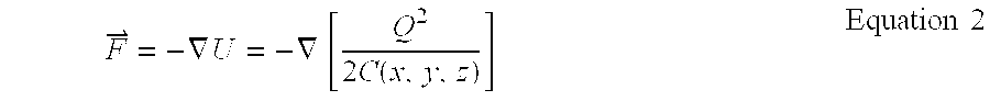
- Forces may be applied to the gyroscope using variable air-gap capacitors formed between one or more plates (or conductive nodes) attached to the proof-mass and one or more plates (or conductive nodes) attached to the substrate. Note that electrostatic forces result between charged capacitor plates. The magnitude and direction of the force is given by the gradient of the potential energy function for the capacitor as shown below.
- an appropriate oscillation in the gyroscope may be generated using a force along a single axis (e.g. the X-axis). Equation 2 implies that any capacitor that varies with displacement along the X-axis will generate an appropriate force. An implementation of a pair of such capacitors is shown in FIG. 2 . This capacitor configuration has a number of advantages including ample room for large displacements along the X-axis without collisions between comb fingers.
- V 1 V DC ⁇ v x
- V 2 ⁇ V DC ⁇ v x Equation 4
- the magnitude of the force is proportional to the control voltage, v x , and the DC bias voltage, V DC . This permits the magnitude and direction of the force to be directly controlled by varying either v x or V DC while maintaining the other voltage constant.
- Some methods of capacitive detection use time-multiplexing (see for example: M. Lemkin, B. E. Boser, “A Three-axis Micromachined Accelerometer With a CMOS Position-Sense Interface and Digital Offset-trim Electronics,” IEEE Journal of Solid-State Circuits, pp. 456-68, April 1999) or frequency multiplexing (see for example Sherman, S. J, et. al., “A Low Cost Monolithic Accelerometer; Product/technology Update,” International Electron Devices Meeting, San Francisco, Calif., December 1992, pp. 501-4) to enable electrostatic forces to be applied to a microstructure and displacement or motion of the microstructure to be sensed using a single set of capacitors.
- An example of an application in which time- or frequency-multiplexing of capacitor function in such a manner may prove useful includes a force-feedback loop.
- the structure may be driven into oscillation using feedback.
- the desired oscillation is achieved by measuring the structure's displacement or velocity then determining the magnitude, and/or phase of the force or forces to apply to the structure.
- the measurement of the structure's displacement and the force(s) applied may be electrostatic as described above.
- the position or velocity detected by the sense interface often reflects relative motion between the two masses, and the forces applied to the two masses may contain a differential force component. Many methods are known to sustain drive-mode oscillation.
- the gyroscope driven-mode and sense-axis may not be perfectly orthogonal, thereby causing quadrature error. Imperfections in elements of the suspension are one possible cause of this non-orthogonality. Phase lag in detection circuitry can lead to quadrature error leakage into the sensor output. Results of this leakage may include large sensor output offsets, output-offset drift, and noise. In addition, large quadrature-error signals may cause saturation of sense-mode interfaces.
- the invention comprises a dual-mass vibratory microstructure, such as a gyroscope, with improved suspension.
- the microstructure comprises a substrate, two proof-masses, and a suspension system.
- the suspension connects the two proof-masses to the substrate.
- the suspension allows for two modes of compliance: the driven and sensing modes.
- the suspension may include a plurality of compliant beams and may include at least one rigid beam that serves as a lever connecting the two proof-masses.
- a further aspect of the invention includes a microstructure and circuitry for canceling errors, termed quadrature error.
- quadrature error An example of one source of quadrature error is imperfections in the manufacturing process.
- Quadrature-error cancellation utilizes electrostatic forces to cancel undesired sense-axis motion either substantially close to in-phase or 180 degrees out-of-phase with drive-mode displacement.
- a nullifying electrostatic force may be applied in-phase with drive-mode position through a differential bias applied to one or more sets of variable capacitors.
- Quadrature-error cancellation may be operated open-loop, in which case the differential bias is constant.
- quadrature-error cancellation may be operated closed-loop, in which case quadrature-error is continuously or periodically measured. The resulting measurement of quadrature error may be used to adjust the differential bias to cancel the error signal.
- FIG. 1 is a conceptual representation of a vibratory rate gyroscope illustrating driven-mode oscillation and sense-mode response.
- FIG. 2 is a perspective view of a set of interdigitated comb-fingers suitable for sustaining proof-mass oscillation along the drive-mode.
- FIG. 3 is a conceptual representation of a gyroscopic dual-mass mechanical sense-element that suppresses deflections resulting from translational accelerations along the sense-axis.
- FIG. 4 is a plan view of a dual-mass gyroscopic mechanical sense-element embodiment that suppresses deflections due to translational accelerations along the sense-axis.
- FIG. 5 is a plan view of the sense-element in FIG. 4 showing important deflections of the driven-mode.
- FIG. 6 is a plan view of the sense-element of FIG. 4 showing important sense-mode deflections in response to a Coriolis acceleration.
- FIG. 7 is a plan view of a second embodiment of the invention that has a modified suspension system and yet has the same major elements.
- FIG. 8 is a plan view of a third embodiment of the invention that has a modified suspension system and yet has the same major elements.
- FIG. 9 is a plan view of a fourth embodiment of the invention that has a modified suspension system and yet has the same major elements.
- FIG. 10 is a plan view of a fifth embodiment of the invention that has a modified suspension system and yet has the same major elements.
- FIG. 11 is a perspective view of two embodiments of a set of comb-fingers suitable for quadrature-error cancellation.
- FIG. 12 is a conceptual representation of proof-mass motions due to quadrature error in a gyroscopic dual-mass mechanical sense-element.
- FIG. 13 is a conceptual representation of proof-mass motions with suppressed quadrature error when quadrature-error cancellation is activated.
- FIG. 14 is a conceptual representation of proof-mass motions with suppressed quadrature error when balanced quadrature-error cancellation is activated.
- a dual-mass gyroscope with an improved suspension system is conceptually illustrated in FIG. 3 .
- the suspension system holds the proof-masses and allows for two modes of compliance.
- One mode of compliance is in the drive mode. This mode of compliance is driven into oscillation thereby supplying the velocity necessary to generate Coriolis acceleration.
- Note the drive-mode motions of the proof-masses are 180 degrees out of phase with respect to each other, as represented by the arrows in FIG. 3 .
- Another mode of compliance is the sense-mode, which may be excited by Coriolis acceleration.
- the Coriolis acceleration has the same magnitude on each proof-mass, but is applied in opposite directions due to the 180-degree phase shift between the two proof-mass motions in the drive mode. Thus, by driving the two masses differentially, a differential Coriolis acceleration is made available for measurement.
- FIG. 4 illustrates a first embodiment of a mechanical sense-element 100 for a dual-mass vibratory rate gyroscope in accordance with the invention.
- the sense-element 100 generates Coriolis acceleration through the interaction of the rotation rate to be measured and the vibrating proof-masses 130 and 131 .
- a suspension system which includes the set of beams 104 through 127 and lever 128 , attaches the proof-masses 130 and 131 to the substrate 101 at two points 102 and 103 defined as anchors.
- most beams in the suspension system are longer than they are wide with aspect ratios exceeding a 10 to 1 length to width ratio. This results in beams that are compliant to bending but relatively stiff to compression and extension.
- each beam may be formed as a single structure as drawn, or a composite structure made from a combination of substantially parallel beams.
- flexure dimensions are defined in the following manner: flexure thickness is defined as the thickness of the substantially planar surface into which the microstructure is formed, flexure width is defined as the smallest characteristic dimension perpendicular to the flexure thickness, and flexure length is defined as a remaining characteristic dimension perpendicular to both the flexure thickness and flexure width.
- the suspended proof-masses 130 and 131 are made to oscillate in an anti-phase motion, the driven mode, which is illustrated in FIG. 5 .
- Driven-mode oscillations result in substantial deflections of beams 104 through 111 , while the remaining beams stay largely straight. Since beams 104 through 111 are principally involved in the driven-mode deflections, the compliance of the driven mode is largely determined by these beams.
- the structure responds to substrate rotation rate by oscillating in an anti-phase motion, the sense-mode, as illustrated in FIG. 6 .
- the compliance of the deflection shown in FIG. 6 is largely determined by the set of beams 112 through 115 that deflect along the Y-axis.
- the remaining beams 116 through 119 and 124 through 127 contribute to the compliance of the sense-mode but are typically not dominant contributors.
- the two proof-masses are forced to move in opposite directions along the Y-axis by the rotating lever 128 and the beams 116 through 127 that connect the lever and the proof-masses.
- additional flexures such as 151 a-d, 152 a-d may be attached between the outside of the proof-masses 130 b, 131 b and the substrate 101 c, anchored by anchors 150 a-c as illustrated in a second embodiment shown in FIG. 7 .
- Levers 222 and 223 force the two proof-masses 202 and 203 to move in opposite directions along the Y-axis, pivoting about the beams 220 and 221 .
- Beams 204 through 221 are axially stiff, yet rotationally compliant and thus transmit common-mode Y-axis forces and accelerations between the proof-masses 202 and 203 , through the levers 222 and 223 , to the anchors 230 and 231 .
- FIG. 9 illustrates a fourth embodiment 100 b of a dual-mass vibratory rate gyroscope of the type shown in FIG. 3 .
- the embodiment shown in FIG. 9 has a different suspension than the first three embodiments, the behaviors and underlying principles of the four suspensions are similar.
- a single lever 128 a is used in conjunction with axially stiff and rotationally compliant beams 116 a and 117 a to enable rotation of the lever while suppressing Y-axis translation of the lever ends.
- the effect of the lever is to constrain the proof-masses 130 a and 131 a to move in a differential fashion along the Y-axis.
- crab-leg suspensions (formed from beams 112 a,c,d,f and 104 a,c,d,f ) connect the proof-masses to the substrate.
- Compliance of the crab-leg suspension beams and compliance of beams 124 a, 125 a, 126 a, 127 a primarily determine compliance of the sense-mode.
- Drive-mode compliance is primarily set by the compliance of the crab-leg beams in conjunction with the compliance of beams 124 a, 125 a, 126 a, 127 a.
- FIG. 10 illustrates a fifth embodiment 201 a of a dual-mass vibratory rate gyroscope of the type shown in FIG. 3 .
- the embodiment shown in FIG. 10 has a different suspension than the first four embodiments, the behaviors and underlying principles of all five suspensions are similar.
- two levers 222 a and 223 a are used in conjunction with axially stiff and rotationally compliant beams 220 a and 221 a to enable rotation of the levers while suppressing Y-axis translation of the lever ends.
- Optional beam 299 decreases compliance along the drive-axis for in-phase proof-mass motion, attenuating displacements due to X-axis translational accelerations.
- the effect of the levers is to constrain the proof-masses 202 a and 203 a to move in a differential fashion along the Y-axis.
- crab-leg suspensions formed from beams 204 a,c,d,f and 240 a,c,d,f ) connect the proof-masses to the substrate.
- Compliance of the crab-leg suspension beams and compliance of beams 208 a, 209 a, 210 a, 211 a primarily determine compliance of the sense-mode.
- Drive-mode compliance is primarily set by the compliance of the crab-leg beams in conjunction with the compliance of beams 208 a, 209 a, 210 a, 211 a.
- FIG. 3 there are several important elements that are common between FIG. 3, FIG. 4, FIG. 7, FIG. 8, FIG. 9, and FIG. 10 .
- These proof-masses are mounted in a suspension that has two principal compliant modes.
- the drive-mode is such that the two proof-masses oscillate differentially (in an anti-phase manner), largely parallel to the drive-or X-axis.
- the sense-mode is such that the two proof-masses are constrained to move in opposite directions largely parallel to the Y-axis.
- the sense-mode is constrained with a lever mechanism 51 , 128 , or 222 and 223 that is attached to the substrate 101 or 229 via anchors 102 and 103 or 230 and 231 using axially stiff yet rotationally compliant beams.
- the suspension allows the two proof-masses to be driven to oscillate differentially and respond differentially to Coriolis acceleration, while other mechanical responses in the sense-axis are suppressed.
- FIG. 11 shows a schematic diagram of two different differential comb-finger structures suitable for reducing quadrature error arising from drive-mode motion coupling into the sense-axis.
- Comb finger 500 ( 550 a,b ) is attached to a proof-mass, while stationary comb-fingers 501 ( 551 ) and 502 ( 552 ) are attached to the substrate.
- Two voltages with respect to the proof-mass are applied to the stationary comb fingers. The voltages may be resolved into common-mode and differential voltage components V and ⁇ V respectively.
- the overlap area of the capacitive plates increases.
- the change in the overlap area causes a corresponding change in the magnitude of the total force along the Y-axis proportional to X-axis position.
- Equation 5 X 0 and Z 0 are the nominal overlap of the quadrature-nulling structure, Y 0 is the nominal separation distance between the movable comb-finger 500 and the stationary comb-fingers, ⁇ 0 is the permittivity of free space, and x is the displacement of the end of comb-finger 500 from the nominal position.
- FIG. 12 is a simplified schematic of a two-mass gyroscope with a differential quadrature-error cancellation structure comprised of comb-fingers 500 ab, 501 ab, and 502 ab.
- Comb-finger structures 500 a and 500 b are attached to each proof-mass 52 a and 53 a to enable cancellation of differential quadrature error.
- Nominal motion of the proof-masses with quadrature-error, with quadrature-error cancellation disabled (all bias voltages set to zero), and with zero rate input is shown in FIG. 12 .
- quadrature-error cancellation shown in FIG. 13, applies voltages that result in cancellation of the undesired differential motion.
- the magnitude and sign of the quadrature-nulling force may be varied. Since quadrature-error is in-phase or 180 degrees out-of-phase with drive-mode displacement, voltages may be chosen to generate forces to null the quadrature error. Bias voltages may be generated open loop. Alternatively, these voltages may be adjusted using feedback of measured quadrature error to drive quadrature-error towards zero.
- a balanced quadrature-nulling structure comprised of comb fingers 500 cdef, 501 cdef, and 502 cdef may be included with the first through fifth embodiments of the invention as schematically shown in FIG. 14 .
- the static displacement shown in FIG. 13 is greatly attenuated through the use of balanced bias forces on each proof-mass.
- Primary mechanical-design factors affecting the noise floor of a vibratory rate gyroscope include the size of the sensor, the driven- and sense-mode resonant frequencies of the structure, and the damping of the resonant modes.
- the mechanical sense-element In order to minimize noise, it is desirable to make the mechanical sense-element as large as possible limited by the fabrication technology and undesirable vibration modes that can occur with large structures.
- operation of the device in a vacuum reduces the air damping of the structure, which also reduces noise.
- the substantially planar nature of the sense-element lends itself well to single-crystal silicon technologies. In these technologies, the structures are typically 10 ⁇ m to 500 ⁇ m thick and occupy an area from 1 mm 2 to 100 mm 2 .
- the sensors may operate in a partial vacuum on the order of 100 mTorr.
- the invention has been described as being advantageous because it may exploit the benefits of single crystal-silicon fabrication technology.
- the embodiments described here may also be fabricated using other technologies and materials including, but not limited to: surface-micromachining, epi-polysilicon, bulk micromachining, plated metal, and quartz.
Abstract
Description


Claims (22)
Priority Applications (1)
| Application Number | Priority Date | Filing Date | Title |
|---|---|---|---|
| US09/321,972 US6230563B1 (en) | 1998-06-09 | 1999-05-28 | Dual-mass vibratory rate gyroscope with suppressed translational acceleration response and quadrature-error correction capability |
Applications Claiming Priority (3)
| Application Number | Priority Date | Filing Date | Title |
|---|---|---|---|
| US8868198P | 1998-06-09 | 1998-06-09 | |
| US9134698P | 1998-07-01 | 1998-07-01 | |
| US09/321,972 US6230563B1 (en) | 1998-06-09 | 1999-05-28 | Dual-mass vibratory rate gyroscope with suppressed translational acceleration response and quadrature-error correction capability |
Publications (1)
| Publication Number | Publication Date |
|---|---|
| US6230563B1 true US6230563B1 (en) | 2001-05-15 |
Family
ID=27376036
Family Applications (1)
| Application Number | Title | Priority Date | Filing Date |
|---|---|---|---|
| US09/321,972 Expired - Lifetime US6230563B1 (en) | 1998-06-09 | 1999-05-28 | Dual-mass vibratory rate gyroscope with suppressed translational acceleration response and quadrature-error correction capability |
Country Status (1)
| Country | Link |
|---|---|
| US (1) | US6230563B1 (en) |
Cited By (94)
| Publication number | Priority date | Publication date | Assignee | Title |
|---|---|---|---|---|
| WO2001071364A1 (en) * | 2000-03-17 | 2001-09-27 | Microsensors, Inc. | Method of canceling quadrature error in an angular rate sensor |
| US6439050B1 (en) * | 2000-03-10 | 2002-08-27 | Melexis | Compensated integrated micro-machined yaw rate sensor with quadrature switching |
| US6453743B1 (en) * | 2000-03-10 | 2002-09-24 | Melexis | Compensated integrated micro-machined yaw rate sensor |
| WO2002103289A1 (en) * | 2001-06-19 | 2002-12-27 | Honeywell International Inc. | Coupled micromachined structure |
| US6509670B2 (en) * | 2000-07-19 | 2003-01-21 | Samsung Electronics Co., Ltd. | Single stage microactuator for multidimensional actuation with multi-folded spring |
| WO2003010492A1 (en) | 2001-07-25 | 2003-02-06 | Northrop Grumman Corporation | Phase insensitive quadrature nulling method and apparatus for coriolis angular rate sensors |
| WO2003021298A2 (en) * | 2001-08-31 | 2003-03-13 | Analog Devices, Inc. | Mems comb-finger actuator |
| US6539803B2 (en) * | 2000-07-07 | 2003-04-01 | Murata Manufacturing Co., Ltd. | External force measuring device |
| GB2384054A (en) * | 2002-01-10 | 2003-07-16 | Murata Manufacturing Co | Angular velocity sensor with four vibrating masses |
| WO2003058167A1 (en) * | 2002-01-12 | 2003-07-17 | Robert Bosch Gmbh | Rotational rate sensor |
| WO2003058166A1 (en) * | 2002-01-12 | 2003-07-17 | Robert Bosch Gmbh | Rotational rate sensor |
| US20040173023A1 (en) * | 2003-03-06 | 2004-09-09 | Hai Yan | Micromachined vibratory gyroscope with electrostatic coupling |
| FR2853731A1 (en) * | 2003-03-31 | 2004-10-15 | Denso Corp | ANGULAR SPEED SENSOR TYPE A VIBRATIONS |
| US20040250620A1 (en) * | 2001-12-20 | 2004-12-16 | Liviu Nicu | Micromachined inertial sensor for measuring rotational movements |
| US20050056094A1 (en) * | 2002-02-06 | 2005-03-17 | Geen John A. | Micromachined apparatus utilizing box suspensions |
| US6868726B2 (en) * | 2000-01-20 | 2005-03-22 | Analog Devices Imi, Inc. | Position sensing with improved linearity |
| US20050062362A1 (en) * | 2003-08-28 | 2005-03-24 | Hongyuan Yang | Oscillatory gyroscope |
| US20050139005A1 (en) * | 2002-02-06 | 2005-06-30 | Analog Devices, Inc. | Micromachined sensor with quadrature suppression |
| US20050150297A1 (en) * | 2004-01-13 | 2005-07-14 | Farrokh Ayazi | High-resolution in-plane tuning fork gyroscope and methods of fabrication |
| US20050166675A1 (en) * | 2004-01-30 | 2005-08-04 | Hobbs Larry P. | Micromachined vibratory gyroscope and method with electronic coupling |
| US6938483B1 (en) | 2004-03-28 | 2005-09-06 | Hai Yan | Phase-locked mechanical resonator pair and its application in micromachined vibration gyroscope |
| US20050229705A1 (en) * | 2004-04-14 | 2005-10-20 | Geen John A | Inertial sensor with a linear array of sensor elements |
| US20050242947A1 (en) * | 2004-04-29 | 2005-11-03 | Tracetech Incorporated | Tracking system and methods thereof |
| US7051590B1 (en) * | 1999-06-15 | 2006-05-30 | Analog Devices Imi, Inc. | Structure for attenuation or cancellation of quadrature error |
| US20060125576A1 (en) * | 2004-10-18 | 2006-06-15 | Ho Gavin K | Highly tunable low-impedance capacitive micromechanical resonators, oscillators, and processes relating thereto |
| US20060144174A1 (en) * | 2004-10-01 | 2006-07-06 | Geen John A | Common centroid micromachine driver |
| US20060213266A1 (en) * | 2005-03-22 | 2006-09-28 | Honeywell International Inc. | Use of electrodes to cancel lift effects in inertial sensors |
| US20060213265A1 (en) * | 2005-03-22 | 2006-09-28 | Honeywell International Inc | Quadrature reduction in mems gyro devices using quad steering voltages |
| US20070180908A1 (en) * | 2006-02-06 | 2007-08-09 | Joseph Seeger | Method and apparatus for electronic cancellation of quadrature error |
| WO2007104742A1 (en) | 2006-03-10 | 2007-09-20 | Continental Teves Ag & Co. Ohg | Rate-of-rotation sensor having a coupling bar |
| US20080072683A1 (en) * | 2006-06-02 | 2008-03-27 | The Board Of Trustees Of The University Of Illinois | Micromachined artificial haircell |
| US20080072682A1 (en) * | 2004-06-04 | 2008-03-27 | The Board Of Trustees Of The University Of Illinois | Artificial lateral line |
| US7421897B2 (en) | 2005-04-14 | 2008-09-09 | Analog Devices, Inc. | Cross-quad and vertically coupled inertial sensors |
| US7444868B2 (en) | 2006-06-29 | 2008-11-04 | Honeywell International Inc. | Force rebalancing for MEMS inertial sensors using time-varying voltages |
| WO2008145823A1 (en) * | 2007-06-01 | 2008-12-04 | Vti Technologies Oy | A method for measuring angular velocity and a vibrating micromechanical sensor of angular velocity |
| US20090064781A1 (en) * | 2007-07-13 | 2009-03-12 | Farrokh Ayazi | Readout method and electronic bandwidth control for a silicon in-plane tuning fork gyroscope |
| DE102007057042A1 (en) | 2007-09-10 | 2009-03-12 | Continental Teves Ag & Co. Ohg | Micromechanical rotation rate sensor with coupling bars and suspension elements for quadrature suppression |
| EP2063223A1 (en) * | 2006-09-15 | 2009-05-27 | Hitachi, Ltd. | Angular velocity sensor |
| US20090249875A1 (en) * | 2005-07-26 | 2009-10-08 | Robert Bosch Gmbh | Rate-of-turn sensor |
| US20100058864A1 (en) * | 2008-09-05 | 2010-03-11 | Industrial Technology Research Institute | Multi-axis capacitive accelerometer |
| US20100126269A1 (en) * | 2008-11-26 | 2010-05-27 | Stmicroelectronics S.R.L. | Microelectromechanical gyroscope with rotary driving motion and improved electrical properties |
| US20100126272A1 (en) * | 2008-11-26 | 2010-05-27 | Stmicroelectronics S.R.L. | Uniaxial or biaxial microelectromechanical gyroscope with improved sensitivity to angular velocity detection |
| US20100132463A1 (en) * | 2008-11-26 | 2010-06-03 | Stmicroelectronics S.R.L | Reading circuit for a multi-axis mems gyroscope having detection directions inclined with respect to the reference axes, and corresponding multi-axis mems gyroscope |
| US20100154541A1 (en) * | 2008-12-23 | 2010-06-24 | Stmicroelectronics S.R.L. | Microelectromechanical gyroscope with enhanced rejection of acceleration noises |
| JP2010175543A (en) * | 2009-01-29 | 2010-08-12 | Robert Bosch Gmbh | Orthogonal compensation method |
| US20100281977A1 (en) * | 2009-05-11 | 2010-11-11 | Stmicroelectronics S.R.I. | Microelectromechanical structure with enhanced rejection of acceleration noise |
| US20110061460A1 (en) * | 2009-09-11 | 2011-03-17 | Invensense, Inc | Extension -mode angular velocity sensor |
| US20110154898A1 (en) * | 2009-12-24 | 2011-06-30 | Stmicroelectronics S.R.L. | Integrated microelectromechanical gyroscope with improved driving structure |
| CN102175236A (en) * | 2011-02-14 | 2011-09-07 | 厦门大学 | Micro gyroscope capable of regulating and reducing quadrature errors |
| US20120291546A1 (en) * | 2008-08-12 | 2012-11-22 | Hitachi, Ltd. | Inertial sensor |
| CN102807189A (en) * | 2011-05-31 | 2012-12-05 | 矽创电子股份有限公司 | Micro-electromechanical device |
| US20130031950A1 (en) * | 2011-07-28 | 2013-02-07 | Stmicroelectronics S.R.L. | Microelectromechanical gyroscope with self-calibration function and method of calibrating a microelectromechanical gyroscope |
| US20130068018A1 (en) * | 2011-09-16 | 2013-03-21 | Invensense, Inc. | Micromachined gyroscope including a guided mass system |
| US8516887B2 (en) | 2010-04-30 | 2013-08-27 | Qualcomm Mems Technologies, Inc. | Micromachined piezoelectric z-axis gyroscope |
| US20130233048A1 (en) * | 2011-09-16 | 2013-09-12 | Invensense, Inc. | Gyroscope self test by applying rotation on coriolis sense mass |
| EP2685211A1 (en) * | 2012-07-09 | 2014-01-15 | Freescale Semiconductor, Inc. | Angular Rate Sensor With Quadrature Error Compensation |
| EP2746724A1 (en) | 2012-12-20 | 2014-06-25 | Tronics Microsystems S.A. | Micromechanical gyroscope |
| US8973439B1 (en) * | 2013-12-23 | 2015-03-10 | Invensense, Inc. | MEMS accelerometer with proof masses moving in anti-phase direction normal to the plane of the substrate |
| US20150115770A1 (en) * | 2013-10-29 | 2015-04-30 | Honeywell International Inc. | All-silicon electrode capacitive transducer on a glass substrate |
| EP2887013A1 (en) | 2013-12-18 | 2015-06-24 | Tronics Microsystems S.A. | MEMS sensor for measuring z-axis angular rate |
| US20150192603A1 (en) * | 2013-12-23 | 2015-07-09 | Invensense, Inc. | Mems accelerometer with proof masses moving in an anti-phase direction |
| US9097524B2 (en) | 2009-09-11 | 2015-08-04 | Invensense, Inc. | MEMS device with improved spring system |
| CN104931033A (en) * | 2014-03-20 | 2015-09-23 | 精工爱普生株式会社 | Oscillator, electronic apparatus, and moving object |
| US9170107B2 (en) * | 2011-09-16 | 2015-10-27 | Invensense, Inc. | Micromachined gyroscope including a guided mass system |
| USRE45792E1 (en) | 2007-09-11 | 2015-11-03 | Stmicroelectronics S.R.L. | High sensitivity microelectromechanical sensor with driving motion |
| US20150316377A1 (en) * | 2013-07-17 | 2015-11-05 | Ramot At Tel-Aviv University Ltd. | Angular rate sensor |
| EP2910953A4 (en) * | 2012-10-16 | 2016-03-23 | Csmc Technologies Fab1 Co Ltd | Parallel plate capacitor and acceleration sensor comprising same |
| US9404747B2 (en) | 2013-10-30 | 2016-08-02 | Stmicroelectroncs S.R.L. | Microelectromechanical gyroscope with compensation of quadrature error drift |
| US9519004B2 (en) * | 2013-11-20 | 2016-12-13 | Sagem Defense Securite | Sensor with moving sensitive element having mixed vibrating and pendular operation, and methods for controlling such a sensor |
| US9726491B2 (en) | 2014-07-25 | 2017-08-08 | Northrop Grumman Systems Corporation | Vibrating-mass gyroscope systems and method |
| US9863769B2 (en) | 2011-09-16 | 2018-01-09 | Invensense, Inc. | MEMS sensor with decoupled drive system |
| US9958271B2 (en) | 2014-01-21 | 2018-05-01 | Invensense, Inc. | Configuration to reduce non-linear motion |
| US9970764B2 (en) | 2009-08-31 | 2018-05-15 | Georgia Tech Research Corporation | Bulk acoustic wave gyroscope with spoked structure |
| US20180306580A1 (en) * | 2017-04-19 | 2018-10-25 | Stmicroelectronics S.R.L. | Mems gyroscope with improved rejection of a quadrature error |
| TWI649565B (en) * | 2012-01-12 | 2019-02-01 | 芬蘭商村田電子公司 | Acceleration sensor structure and its use |
| US10203352B2 (en) | 2016-08-04 | 2019-02-12 | Analog Devices, Inc. | Anchor tracking apparatus for in-plane accelerometers and related methods |
| US10203351B2 (en) | 2014-10-03 | 2019-02-12 | Analog Devices, Inc. | MEMS accelerometer with Z axis anchor tracking |
| CN109444467A (en) * | 2018-12-29 | 2019-03-08 | 深迪半导体(上海)有限公司 | A kind of three axis capacitive accelerometers of shared mass block |
| US10261105B2 (en) | 2017-02-10 | 2019-04-16 | Analog Devices, Inc. | Anchor tracking for MEMS accelerometers |
| US10352960B1 (en) * | 2015-10-30 | 2019-07-16 | Garmin International, Inc. | Free mass MEMS accelerometer |
| DE102009039584B4 (en) | 2008-09-02 | 2019-08-14 | Denso Corporation | Angular rate sensor |
| US10415968B2 (en) | 2016-12-19 | 2019-09-17 | Analog Devices, Inc. | Synchronized mass gyroscope |
| US10514259B2 (en) | 2016-08-31 | 2019-12-24 | Analog Devices, Inc. | Quad proof mass MEMS gyroscope with outer couplers and related methods |
| US10598690B2 (en) | 2011-09-12 | 2020-03-24 | Stmicroelectronics S.R.L. | Microelectromechanical device incorporating a gyroscope and an accelerometer |
| US10627235B2 (en) | 2016-12-19 | 2020-04-21 | Analog Devices, Inc. | Flexural couplers for microelectromechanical systems (MEMS) devices |
| US10697774B2 (en) | 2016-12-19 | 2020-06-30 | Analog Devices, Inc. | Balanced runners synchronizing motion of masses in micromachined devices |
| US10866258B2 (en) | 2018-07-20 | 2020-12-15 | Honeywell International Inc. | In-plane translational vibrating beam accelerometer with mechanical isolation and 4-fold symmetry |
| US10894713B2 (en) * | 2004-10-08 | 2021-01-19 | Stmicroelectronics S.R.L. | Temperature-compensated micro-electromechanical device, and method of temperature compensation in a micro-electromechanical device |
| US10914584B2 (en) | 2011-09-16 | 2021-02-09 | Invensense, Inc. | Drive and sense balanced, semi-coupled 3-axis gyroscope |
| US10948294B2 (en) | 2018-04-05 | 2021-03-16 | Analog Devices, Inc. | MEMS gyroscopes with in-line springs and related systems and methods |
| US11193771B1 (en) | 2020-06-05 | 2021-12-07 | Analog Devices, Inc. | 3-axis gyroscope with rotational vibration rejection |
| US11686581B2 (en) | 2020-06-08 | 2023-06-27 | Analog Devices, Inc. | Stress-relief MEMS gyroscope |
| US11692825B2 (en) | 2020-06-08 | 2023-07-04 | Analog Devices, Inc. | Drive and sense stress relief apparatus |
| US11698257B2 (en) | 2020-08-24 | 2023-07-11 | Analog Devices, Inc. | Isotropic attenuated motion gyroscope |
Citations (38)
| Publication number | Priority date | Publication date | Assignee | Title |
|---|---|---|---|---|
| US4061043A (en) | 1976-03-29 | 1977-12-06 | John Callender Stiles | Electrostatic rate gyroscope |
| USRE32931E (en) | 1984-01-23 | 1989-05-30 | Piezoelectric Technology Investors, Inc. | Vibratory angular rate sensor system |
| USRE33479E (en) | 1984-01-23 | 1990-12-11 | Piezoelectric Technology Investors | Vibratory angular rate sensing system |
| US5016072A (en) | 1988-01-13 | 1991-05-14 | The Charles Stark Draper Laboratory, Inc. | Semiconductor chip gyroscopic transducer |
| US5025346A (en) | 1989-02-17 | 1991-06-18 | Regents Of The University Of California | Laterally driven resonant microstructures |
| US5203208A (en) | 1991-04-29 | 1993-04-20 | The Charles Stark Draper Laboratory | Symmetrical micromechanical gyroscope |
| US5349855A (en) | 1992-04-07 | 1994-09-27 | The Charles Stark Draper Laboratory, Inc. | Comb drive micromechanical tuning fork gyro |
| US5383362A (en) | 1993-02-01 | 1995-01-24 | General Motors Corporation | Control for vibratory gyroscope |
| US5392650A (en) | 1991-01-11 | 1995-02-28 | Northrop Grumman Corporation | Micromachined accelerometer gyroscope |
| US5450751A (en) | 1993-05-04 | 1995-09-19 | General Motors Corporation | Microstructure for vibratory gyroscope |
| US5488863A (en) | 1993-04-16 | 1996-02-06 | Murata Manufacturing Co., Ltd. | Angular velocity sensor making use of tuning fork vibration |
| US5505084A (en) | 1991-09-11 | 1996-04-09 | The Charles Stark Draper Laboratory, Inc. | Micromechanical tuning fork angular rate sensor |
| US5511420A (en) | 1994-12-01 | 1996-04-30 | Analog Devices, Inc. | Electric field attraction minimization circuit |
| US5563343A (en) | 1993-05-26 | 1996-10-08 | Cornell Research Foundation, Inc. | Microelectromechanical lateral accelerometer |
| US5565625A (en) | 1994-12-01 | 1996-10-15 | Analog Devices, Inc. | Sensor with separate actuator and sense fingers |
| US5597955A (en) | 1992-06-11 | 1997-01-28 | Societe D'applications Generales D'electricite Et De Mecanique Sagem | Vibrating beam gyroscopic measuring apparatus |
| US5635739A (en) | 1990-02-14 | 1997-06-03 | The Charles Stark Draper Laboratory, Inc. | Micromechanical angular accelerometer with auxiliary linear accelerometer |
| US5635638A (en) | 1995-06-06 | 1997-06-03 | Analog Devices, Inc. | Coupling for multiple masses in a micromachined device |
| US5635640A (en) | 1995-06-06 | 1997-06-03 | Analog Devices, Inc. | Micromachined device with rotationally vibrated masses |
| US5635639A (en) | 1991-09-11 | 1997-06-03 | The Charles Stark Draper Laboratory, Inc. | Micromechanical tuning fork angular rate sensor |
| US5656777A (en) | 1996-06-13 | 1997-08-12 | Alliedsignal, Inc. | Miniature box vibrating gyroscope |
| US5696420A (en) | 1993-11-17 | 1997-12-09 | Sony Corporation | Vibration type gyroscope apparatus |
| US5698784A (en) | 1996-01-24 | 1997-12-16 | Gyration, Inc. | Vibratory rate gyroscope and methods of assembly and operation |
| US5739410A (en) | 1994-08-24 | 1998-04-14 | British Aerospace Public Limited Company | Method for matching vibration mode frequencies on a vibrating structure |
| US5747690A (en) | 1995-12-27 | 1998-05-05 | Samsung Electronics Co., Ltd. | Vibratory microgyroscope |
| US5747961A (en) | 1995-10-11 | 1998-05-05 | The Charles Stark Draper Laboratory, Inc. | Beat frequency motor position detection scheme for tuning fork gyroscope and other sensors |
| US5753817A (en) | 1995-12-27 | 1998-05-19 | Samsung Electronics Co., Ltd. | Microgyroscope with vibratory structure having a multitude of grooves |
| US5757103A (en) | 1995-05-25 | 1998-05-26 | Samsung Electronics Co., Ltd. | Tuning fork type gyroscope |
| US5767405A (en) | 1992-04-07 | 1998-06-16 | The Charles Stark Draper Laboratory, Inc. | Comb-drive micromechanical tuning fork gyroscope with piezoelectric readout |
| US5780739A (en) | 1995-05-25 | 1998-07-14 | Samsung Electronics Co., Ltd. | Tuning fork type gyroscope |
| US5780740A (en) | 1995-10-27 | 1998-07-14 | Samsung Electronics Co., Ltd. | Vibratory structure, method for controlling natural frequency thereof, and actuator, sensor, accelerator, gyroscope and gyroscope natural frequency controlling method using vibratory structure |
| US5783973A (en) | 1997-02-24 | 1998-07-21 | The Charles Stark Draper Laboratory, Inc. | Temperature insensitive silicon oscillator and precision voltage reference formed therefrom |
| US5783897A (en) | 1994-12-27 | 1998-07-21 | Murata Manufacturing Co., Ltd. | Vibrating gyroscope |
| US5783749A (en) | 1995-12-07 | 1998-07-21 | Electronics And Telecommunications Research Institute | Vibrating disk type micro-gyroscope |
| US5895850A (en) | 1994-04-23 | 1999-04-20 | Robert Bosch Gmbh | Micromechanical resonator of a vibration gyrometer |
| US5908986A (en) | 1996-03-01 | 1999-06-01 | Nissan Motor Co., Ltd. | Angular velocity sensor |
| US5911156A (en) | 1997-02-24 | 1999-06-08 | The Charles Stark Draper Laboratory, Inc. | Split electrode to minimize charge transients, motor amplitude mismatch errors, and sensitivity to vertical translation in tuning fork gyros and other devices |
| US5920012A (en) * | 1998-06-16 | 1999-07-06 | Boeing North American | Micromechanical inertial sensor |
-
1999
- 1999-05-28 US US09/321,972 patent/US6230563B1/en not_active Expired - Lifetime
Patent Citations (39)
| Publication number | Priority date | Publication date | Assignee | Title |
|---|---|---|---|---|
| US4061043A (en) | 1976-03-29 | 1977-12-06 | John Callender Stiles | Electrostatic rate gyroscope |
| USRE32931E (en) | 1984-01-23 | 1989-05-30 | Piezoelectric Technology Investors, Inc. | Vibratory angular rate sensor system |
| USRE33479E (en) | 1984-01-23 | 1990-12-11 | Piezoelectric Technology Investors | Vibratory angular rate sensing system |
| US5016072A (en) | 1988-01-13 | 1991-05-14 | The Charles Stark Draper Laboratory, Inc. | Semiconductor chip gyroscopic transducer |
| US5025346A (en) | 1989-02-17 | 1991-06-18 | Regents Of The University Of California | Laterally driven resonant microstructures |
| US5635739A (en) | 1990-02-14 | 1997-06-03 | The Charles Stark Draper Laboratory, Inc. | Micromechanical angular accelerometer with auxiliary linear accelerometer |
| US5392650A (en) | 1991-01-11 | 1995-02-28 | Northrop Grumman Corporation | Micromachined accelerometer gyroscope |
| US5203208A (en) | 1991-04-29 | 1993-04-20 | The Charles Stark Draper Laboratory | Symmetrical micromechanical gyroscope |
| US5635639A (en) | 1991-09-11 | 1997-06-03 | The Charles Stark Draper Laboratory, Inc. | Micromechanical tuning fork angular rate sensor |
| US5505084A (en) | 1991-09-11 | 1996-04-09 | The Charles Stark Draper Laboratory, Inc. | Micromechanical tuning fork angular rate sensor |
| US5349855A (en) | 1992-04-07 | 1994-09-27 | The Charles Stark Draper Laboratory, Inc. | Comb drive micromechanical tuning fork gyro |
| US5767405A (en) | 1992-04-07 | 1998-06-16 | The Charles Stark Draper Laboratory, Inc. | Comb-drive micromechanical tuning fork gyroscope with piezoelectric readout |
| US5597955A (en) | 1992-06-11 | 1997-01-28 | Societe D'applications Generales D'electricite Et De Mecanique Sagem | Vibrating beam gyroscopic measuring apparatus |
| US5383362A (en) | 1993-02-01 | 1995-01-24 | General Motors Corporation | Control for vibratory gyroscope |
| US5488863A (en) | 1993-04-16 | 1996-02-06 | Murata Manufacturing Co., Ltd. | Angular velocity sensor making use of tuning fork vibration |
| US5450751A (en) | 1993-05-04 | 1995-09-19 | General Motors Corporation | Microstructure for vibratory gyroscope |
| US5563343A (en) | 1993-05-26 | 1996-10-08 | Cornell Research Foundation, Inc. | Microelectromechanical lateral accelerometer |
| US5696420A (en) | 1993-11-17 | 1997-12-09 | Sony Corporation | Vibration type gyroscope apparatus |
| US5895850A (en) | 1994-04-23 | 1999-04-20 | Robert Bosch Gmbh | Micromechanical resonator of a vibration gyrometer |
| US5739410A (en) | 1994-08-24 | 1998-04-14 | British Aerospace Public Limited Company | Method for matching vibration mode frequencies on a vibrating structure |
| US5565625A (en) | 1994-12-01 | 1996-10-15 | Analog Devices, Inc. | Sensor with separate actuator and sense fingers |
| US5511420A (en) | 1994-12-01 | 1996-04-30 | Analog Devices, Inc. | Electric field attraction minimization circuit |
| US5783897A (en) | 1994-12-27 | 1998-07-21 | Murata Manufacturing Co., Ltd. | Vibrating gyroscope |
| US5757103A (en) | 1995-05-25 | 1998-05-26 | Samsung Electronics Co., Ltd. | Tuning fork type gyroscope |
| US5780739A (en) | 1995-05-25 | 1998-07-14 | Samsung Electronics Co., Ltd. | Tuning fork type gyroscope |
| US5635638A (en) | 1995-06-06 | 1997-06-03 | Analog Devices, Inc. | Coupling for multiple masses in a micromachined device |
| US5869760A (en) | 1995-06-06 | 1999-02-09 | Analog Devices, Inc. | Micromachined device with rotationally vibrated masses |
| US5635640A (en) | 1995-06-06 | 1997-06-03 | Analog Devices, Inc. | Micromachined device with rotationally vibrated masses |
| US5747961A (en) | 1995-10-11 | 1998-05-05 | The Charles Stark Draper Laboratory, Inc. | Beat frequency motor position detection scheme for tuning fork gyroscope and other sensors |
| US5780740A (en) | 1995-10-27 | 1998-07-14 | Samsung Electronics Co., Ltd. | Vibratory structure, method for controlling natural frequency thereof, and actuator, sensor, accelerator, gyroscope and gyroscope natural frequency controlling method using vibratory structure |
| US5783749A (en) | 1995-12-07 | 1998-07-21 | Electronics And Telecommunications Research Institute | Vibrating disk type micro-gyroscope |
| US5747690A (en) | 1995-12-27 | 1998-05-05 | Samsung Electronics Co., Ltd. | Vibratory microgyroscope |
| US5753817A (en) | 1995-12-27 | 1998-05-19 | Samsung Electronics Co., Ltd. | Microgyroscope with vibratory structure having a multitude of grooves |
| US5698784A (en) | 1996-01-24 | 1997-12-16 | Gyration, Inc. | Vibratory rate gyroscope and methods of assembly and operation |
| US5908986A (en) | 1996-03-01 | 1999-06-01 | Nissan Motor Co., Ltd. | Angular velocity sensor |
| US5656777A (en) | 1996-06-13 | 1997-08-12 | Alliedsignal, Inc. | Miniature box vibrating gyroscope |
| US5783973A (en) | 1997-02-24 | 1998-07-21 | The Charles Stark Draper Laboratory, Inc. | Temperature insensitive silicon oscillator and precision voltage reference formed therefrom |
| US5911156A (en) | 1997-02-24 | 1999-06-08 | The Charles Stark Draper Laboratory, Inc. | Split electrode to minimize charge transients, motor amplitude mismatch errors, and sensitivity to vertical translation in tuning fork gyros and other devices |
| US5920012A (en) * | 1998-06-16 | 1999-07-06 | Boeing North American | Micromechanical inertial sensor |
Non-Patent Citations (5)
| Title |
|---|
| Clark, W.A., Howe, R.T., Horowitz, R., "Surface Micromachined Z-axis Vibratory Rate Gyroscope," IEEE Solid-State Sensor and Actuator Workshop, Hilton Head Island, SC, pp. 283-287, Jun. 1996. |
| Clark, W.A., Micromachined Vibratory Rate Gyroscopes, Doctoral Dissertation, University of California, 1997. |
| Geen, J.A., "A Path to Low Cost Gyroscopy," IEEE Solid-State Sensor and Actuator Workshop, Hilton Head Island, SC, pp. 51-54, Jun. 1998. |
| Juneau, T., Pisano, A.P., "Micromachined Dual Input Axis Angular Rate Sensor," IEEE Solid-State Sensor and Actuator Workshop, Hilton Head Island, SC, pp. 299-302, Jun. 1996. |
| Juneau, T.N., Micromachined Dual Input Axis Rate Gyroscope, Doctoral Dissertation, University of California, 1997. |
Cited By (214)
| Publication number | Priority date | Publication date | Assignee | Title |
|---|---|---|---|---|
| US7051590B1 (en) * | 1999-06-15 | 2006-05-30 | Analog Devices Imi, Inc. | Structure for attenuation or cancellation of quadrature error |
| US6868726B2 (en) * | 2000-01-20 | 2005-03-22 | Analog Devices Imi, Inc. | Position sensing with improved linearity |
| US6453743B1 (en) * | 2000-03-10 | 2002-09-24 | Melexis | Compensated integrated micro-machined yaw rate sensor |
| US6439050B1 (en) * | 2000-03-10 | 2002-08-27 | Melexis | Compensated integrated micro-machined yaw rate sensor with quadrature switching |
| US6370937B2 (en) * | 2000-03-17 | 2002-04-16 | Microsensors, Inc. | Method of canceling quadrature error in an angular rate sensor |
| WO2001071364A1 (en) * | 2000-03-17 | 2001-09-27 | Microsensors, Inc. | Method of canceling quadrature error in an angular rate sensor |
| US6539803B2 (en) * | 2000-07-07 | 2003-04-01 | Murata Manufacturing Co., Ltd. | External force measuring device |
| US6509670B2 (en) * | 2000-07-19 | 2003-01-21 | Samsung Electronics Co., Ltd. | Single stage microactuator for multidimensional actuation with multi-folded spring |
| WO2002103289A1 (en) * | 2001-06-19 | 2002-12-27 | Honeywell International Inc. | Coupled micromachined structure |
| US6981414B2 (en) * | 2001-06-19 | 2006-01-03 | Honeywell International Inc. | Coupled micromachined structure |
| US20040255672A1 (en) * | 2001-06-19 | 2004-12-23 | Honeywell International Inc. | Coupled micromachined structure |
| US6722197B2 (en) * | 2001-06-19 | 2004-04-20 | Honeywell International Inc. | Coupled micromachined structure |
| EP1412698A1 (en) * | 2001-07-25 | 2004-04-28 | Northrop Grumman Corporation | Phase insensitive quadrature nulling method and apparatus for coriolis angular rate sensors |
| WO2003010492A1 (en) | 2001-07-25 | 2003-02-06 | Northrop Grumman Corporation | Phase insensitive quadrature nulling method and apparatus for coriolis angular rate sensors |
| WO2003021298A2 (en) * | 2001-08-31 | 2003-03-13 | Analog Devices, Inc. | Mems comb-finger actuator |
| WO2003021298A3 (en) * | 2001-08-31 | 2003-09-04 | Analog Devices Inc | Mems comb-finger actuator |
| US20040250620A1 (en) * | 2001-12-20 | 2004-12-16 | Liviu Nicu | Micromachined inertial sensor for measuring rotational movements |
| US7210347B2 (en) * | 2001-12-20 | 2007-05-01 | Thales | Micromachined inertial sensor for measuring rotational movements |
| GB2384054B (en) * | 2002-01-10 | 2004-06-16 | Murata Manufacturing Co | Angular velocity sensor |
| US6742390B2 (en) | 2002-01-10 | 2004-06-01 | Murata Manufacturing Co., Ltd. | Angular velocity sensor |
| CN100354603C (en) * | 2002-01-10 | 2007-12-12 | 株式会社村田制作所 | Angular velocity sensor |
| GB2384054A (en) * | 2002-01-10 | 2003-07-16 | Murata Manufacturing Co | Angular velocity sensor with four vibrating masses |
| US20040123660A1 (en) * | 2002-01-12 | 2004-07-01 | Rainer Willig | Rotational rate sensor |
| US7316161B2 (en) | 2002-01-12 | 2008-01-08 | Robert Bosch Gmbh | Rotation rate sensor |
| US20040206176A1 (en) * | 2002-01-12 | 2004-10-21 | Rainer Willig | Rotation rate sensor |
| WO2003058166A1 (en) * | 2002-01-12 | 2003-07-17 | Robert Bosch Gmbh | Rotational rate sensor |
| US7313958B2 (en) | 2002-01-12 | 2008-01-01 | Robert Bosch Gmbh | Rotational rate sensor |
| WO2003058167A1 (en) * | 2002-01-12 | 2003-07-17 | Robert Bosch Gmbh | Rotational rate sensor |
| JP2005514609A (en) * | 2002-01-12 | 2005-05-19 | ローベルト ボツシユ ゲゼルシヤフト ミツト ベシユレンクテル ハフツング | Rotational speed sensor |
| US7032451B2 (en) | 2002-02-06 | 2006-04-25 | Analog Devices, Inc. | Micromachined sensor with quadrature suppression |
| US7204144B2 (en) | 2002-02-06 | 2007-04-17 | Analog Devices, Inc. | Micromachined apparatus with drive/sensing fingers in coupling levers |
| US20060179945A1 (en) * | 2002-02-06 | 2006-08-17 | Geen John A | Micromachined apparatus with co-linear drive arrays |
| US7357025B2 (en) | 2002-02-06 | 2008-04-15 | Analog Devices, Inc. | Micromachined apparatus with co-linear drive arrays |
| US20050139005A1 (en) * | 2002-02-06 | 2005-06-30 | Analog Devices, Inc. | Micromachined sensor with quadrature suppression |
| US20050056094A1 (en) * | 2002-02-06 | 2005-03-17 | Geen John A. | Micromachined apparatus utilizing box suspensions |
| US20060191340A1 (en) * | 2002-02-06 | 2006-08-31 | Geen John A | Micromachined apparatus with split vibratory masses |
| US7216539B2 (en) | 2002-02-06 | 2007-05-15 | Analog Devices, Inc. | Micromachined apparatus with split vibratory masses |
| US20060191339A1 (en) * | 2002-02-06 | 2006-08-31 | Geen John A | Micromachined apparatus with drive/sensing fingers in coupling levers |
| US7089792B2 (en) | 2002-02-06 | 2006-08-15 | Analod Devices, Inc. | Micromachined apparatus utilizing box suspensions |
| US6966224B2 (en) | 2003-03-06 | 2005-11-22 | Bei Technologies, Inc. | Micromachined vibratory gyroscope with electrostatic coupling |
| WO2004081495A3 (en) * | 2003-03-06 | 2005-04-21 | Bei Technologies Inc | Micromachined vibratory gyroscope with electrostatic coupling |
| US20040173023A1 (en) * | 2003-03-06 | 2004-09-09 | Hai Yan | Micromachined vibratory gyroscope with electrostatic coupling |
| FR2853731A1 (en) * | 2003-03-31 | 2004-10-15 | Denso Corp | ANGULAR SPEED SENSOR TYPE A VIBRATIONS |
| US20050062362A1 (en) * | 2003-08-28 | 2005-03-24 | Hongyuan Yang | Oscillatory gyroscope |
| US7043985B2 (en) | 2004-01-13 | 2006-05-16 | Georgia Tech Research Corporation | High-resolution in-plane tuning fork gyroscope and methods of fabrication |
| US20050150297A1 (en) * | 2004-01-13 | 2005-07-14 | Farrokh Ayazi | High-resolution in-plane tuning fork gyroscope and methods of fabrication |
| US6964195B2 (en) | 2004-01-30 | 2005-11-15 | Bei Technologies, Inc. | Micromachined vibratory gyroscope and method with electronic coupling |
| US20050166675A1 (en) * | 2004-01-30 | 2005-08-04 | Hobbs Larry P. | Micromachined vibratory gyroscope and method with electronic coupling |
| US20050210977A1 (en) * | 2004-03-28 | 2005-09-29 | Hai Yan | A phase-locked mechanical resonator pair and its application in micromachined vibration gyroscope |
| US6938483B1 (en) | 2004-03-28 | 2005-09-06 | Hai Yan | Phase-locked mechanical resonator pair and its application in micromachined vibration gyroscope |
| CN1954193B (en) * | 2004-04-14 | 2010-09-01 | 模拟设备公司 | Coupling apparatus for inertial sensors |
| JP2007532917A (en) * | 2004-04-14 | 2007-11-15 | アナログ デバイシス, インコーポレイテッド | Inertial sensor with linearly arrayed sensor elements |
| US20050229705A1 (en) * | 2004-04-14 | 2005-10-20 | Geen John A | Inertial sensor with a linear array of sensor elements |
| US7347094B2 (en) | 2004-04-14 | 2008-03-25 | Analog Devices, Inc. | Coupling apparatus for inertial sensors |
| US7287428B2 (en) | 2004-04-14 | 2007-10-30 | Analog Devices, Inc. | Inertial sensor with a linear array of sensor elements |
| US20050229703A1 (en) * | 2004-04-14 | 2005-10-20 | Geen John A | Coupling apparatus for inertial sensors |
| WO2005103621A1 (en) | 2004-04-14 | 2005-11-03 | Analog Devices, Inc. | Coupling apparatus for inertial sensors |
| US20070013512A1 (en) * | 2004-04-29 | 2007-01-18 | Burneske Gregory W | Tracking system and methods thereof |
| US20090015399A1 (en) * | 2004-04-29 | 2009-01-15 | Tracetech Incorporated | Tracking System And Methods Thereof |
| US8279062B2 (en) | 2004-04-29 | 2012-10-02 | Amstr. Investments 19 K.G., Llc | Tracking system and methods thereof |
| US20050242947A1 (en) * | 2004-04-29 | 2005-11-03 | Tracetech Incorporated | Tracking system and methods thereof |
| US7106189B2 (en) | 2004-04-29 | 2006-09-12 | Tracetech Incorporated | Tracking system and methods thereof |
| US7626499B2 (en) | 2004-04-29 | 2009-12-01 | Burneske Gregory W | Tracking system and methods thereof |
| US7644624B2 (en) | 2004-06-04 | 2010-01-12 | The Board Of Trustees Of The University Of Illinois | Artificial lateral line |
| US8056419B2 (en) | 2004-06-04 | 2011-11-15 | The Board Of Trustees Of The University Of Illinois | Artificial lateral line |
| US20080072682A1 (en) * | 2004-06-04 | 2008-03-27 | The Board Of Trustees Of The University Of Illinois | Artificial lateral line |
| US7478557B2 (en) | 2004-10-01 | 2009-01-20 | Analog Devices, Inc. | Common centroid micromachine driver |
| US20060144174A1 (en) * | 2004-10-01 | 2006-07-06 | Geen John A | Common centroid micromachine driver |
| US10894713B2 (en) * | 2004-10-08 | 2021-01-19 | Stmicroelectronics S.R.L. | Temperature-compensated micro-electromechanical device, and method of temperature compensation in a micro-electromechanical device |
| US7511870B2 (en) * | 2004-10-18 | 2009-03-31 | Georgia Tech Research Corp. | Highly tunable low-impedance capacitive micromechanical resonators, oscillators, and processes relating thereto |
| US20060125576A1 (en) * | 2004-10-18 | 2006-06-15 | Ho Gavin K | Highly tunable low-impedance capacitive micromechanical resonators, oscillators, and processes relating thereto |
| US7213458B2 (en) | 2005-03-22 | 2007-05-08 | Honeywell International Inc. | Quadrature reduction in MEMS gyro devices using quad steering voltages |
| US7231824B2 (en) | 2005-03-22 | 2007-06-19 | Honeywell International Inc. | Use of electrodes to cancel lift effects in inertial sensors |
| US20060213265A1 (en) * | 2005-03-22 | 2006-09-28 | Honeywell International Inc | Quadrature reduction in mems gyro devices using quad steering voltages |
| US20060213266A1 (en) * | 2005-03-22 | 2006-09-28 | Honeywell International Inc. | Use of electrodes to cancel lift effects in inertial sensors |
| US7421897B2 (en) | 2005-04-14 | 2008-09-09 | Analog Devices, Inc. | Cross-quad and vertically coupled inertial sensors |
| US7694561B2 (en) * | 2005-07-26 | 2010-04-13 | Robert Bosch Gmbh | Rate-of-turn sensor |
| US20090249875A1 (en) * | 2005-07-26 | 2009-10-08 | Robert Bosch Gmbh | Rate-of-turn sensor |
| US20070180908A1 (en) * | 2006-02-06 | 2007-08-09 | Joseph Seeger | Method and apparatus for electronic cancellation of quadrature error |
| US7290435B2 (en) * | 2006-02-06 | 2007-11-06 | Invensense Inc. | Method and apparatus for electronic cancellation of quadrature error |
| US8261614B2 (en) | 2006-03-10 | 2012-09-11 | Continental Teves Ag & Co. Ohg | Rotational speed sensor having a coupling bar |
| US20100037690A1 (en) * | 2006-03-10 | 2010-02-18 | Continental Teves Ag & Co. Ohg | Rotational Speed Sensor Having A Coupling Bar |
| WO2007104742A1 (en) | 2006-03-10 | 2007-09-20 | Continental Teves Ag & Co. Ohg | Rate-of-rotation sensor having a coupling bar |
| JP2009529666A (en) * | 2006-03-10 | 2009-08-20 | コンティネンタル・テーベス・アクチエンゲゼルシヤフト・ウント・コンパニー・オッフェネ・ハンデルスゲゼルシヤフト | Rotational speed sensor with connecting rod |
| US20080072683A1 (en) * | 2006-06-02 | 2008-03-27 | The Board Of Trustees Of The University Of Illinois | Micromachined artificial haircell |
| US7661319B2 (en) * | 2006-06-02 | 2010-02-16 | The Board Of Trustees Of The University Of Illinois | Micromachined artificial haircell |
| US7444868B2 (en) | 2006-06-29 | 2008-11-04 | Honeywell International Inc. | Force rebalancing for MEMS inertial sensors using time-varying voltages |
| EP2063223A1 (en) * | 2006-09-15 | 2009-05-27 | Hitachi, Ltd. | Angular velocity sensor |
| EP2063223A4 (en) * | 2006-09-15 | 2012-01-25 | Hitachi Ltd | Angular velocity sensor |
| WO2008145823A1 (en) * | 2007-06-01 | 2008-12-04 | Vti Technologies Oy | A method for measuring angular velocity and a vibrating micromechanical sensor of angular velocity |
| US8474316B2 (en) | 2007-06-01 | 2013-07-02 | Murata Electronics Oy | Method for measuring angular velocity and a vibrating micromechanical sensor of angular velocity |
| CN101688884B (en) * | 2007-06-01 | 2012-07-04 | Vti技术有限公司 | A method for measuring angular velocity and a vibrating micromechanical sensor of angular velocity |
| US20080314144A1 (en) * | 2007-06-01 | 2008-12-25 | Vti Technologies Oy | Method for measuring angular velocity and a vibrating micromechanical sensor of angular velocity |
| US8061201B2 (en) | 2007-07-13 | 2011-11-22 | Georgia Tech Research Corporation | Readout method and electronic bandwidth control for a silicon in-plane tuning fork gyroscope |
| US20090064781A1 (en) * | 2007-07-13 | 2009-03-12 | Farrokh Ayazi | Readout method and electronic bandwidth control for a silicon in-plane tuning fork gyroscope |
| US8677821B2 (en) | 2007-07-13 | 2014-03-25 | Georgia Tech Research Coporation | Readout method and electronic bandwidth control for a silicon in-plane tuning fork gyroscope |
| US8549919B2 (en) * | 2007-09-10 | 2013-10-08 | Continental Teves Ag & Co. Ohg | Micromechanical rotation rate sensor with a coupling bar and suspension spring elements for quadrature suppression |
| US20100186507A1 (en) * | 2007-09-10 | 2010-07-29 | Guenthner Stefan | Micromechanical rotation rate sensor with a coupling bar and suspension spring elements for quadrature suppression |
| DE102007057042A1 (en) | 2007-09-10 | 2009-03-12 | Continental Teves Ag & Co. Ohg | Micromechanical rotation rate sensor with coupling bars and suspension elements for quadrature suppression |
| WO2009033915A1 (en) * | 2007-09-10 | 2009-03-19 | Continental Teves Ag & Co. Ohg | Micromechanical rate-of-rotation sensor |
| USRE45855E1 (en) | 2007-09-11 | 2016-01-19 | Stmicroelectronics S.R.L. | Microelectromechanical sensor with improved mechanical decoupling of sensing and driving modes |
| USRE45792E1 (en) | 2007-09-11 | 2015-11-03 | Stmicroelectronics S.R.L. | High sensitivity microelectromechanical sensor with driving motion |
| US20120291546A1 (en) * | 2008-08-12 | 2012-11-22 | Hitachi, Ltd. | Inertial sensor |
| US8943890B2 (en) * | 2008-08-12 | 2015-02-03 | Hitachi, Ltd. | Inertial sensor |
| DE102009039584B4 (en) | 2008-09-02 | 2019-08-14 | Denso Corporation | Angular rate sensor |
| US8459114B2 (en) * | 2008-09-05 | 2013-06-11 | Industrial Technology Research Institute | Multi-axis capacitive accelerometer |
| US20100058864A1 (en) * | 2008-09-05 | 2010-03-11 | Industrial Technology Research Institute | Multi-axis capacitive accelerometer |
| US8413506B2 (en) | 2008-11-26 | 2013-04-09 | Stmicroelectronics S.R.L. | Microelectromechanical gyroscope with rotary driving motion and improved electrical properties |
| US8813565B2 (en) | 2008-11-26 | 2014-08-26 | Stmicroelectronics S.R.L. | Reading circuit for MEMS gyroscope having inclined detection directions |
| US20100126272A1 (en) * | 2008-11-26 | 2010-05-27 | Stmicroelectronics S.R.L. | Uniaxial or biaxial microelectromechanical gyroscope with improved sensitivity to angular velocity detection |
| US8661897B2 (en) | 2008-11-26 | 2014-03-04 | Stmicroelectronics S.R.L. | Uniaxial or biaxial microelectromechanical gyroscope with improved sensitivity to angular velocity detection |
| US20100132463A1 (en) * | 2008-11-26 | 2010-06-03 | Stmicroelectronics S.R.L | Reading circuit for a multi-axis mems gyroscope having detection directions inclined with respect to the reference axes, and corresponding multi-axis mems gyroscope |
| US8459109B2 (en) | 2008-11-26 | 2013-06-11 | Stmicroelectronics S.R.L. | Reading circuit for a multi-axis MEMS gyroscope having detection directions inclined with respect to the reference axes |
| US8312769B2 (en) | 2008-11-26 | 2012-11-20 | Stmicroelectronics S.R.L. | Uniaxial or biaxial microelectromechanical gyroscope with improved sensitivity to angular velocity detection |
| US9470526B2 (en) | 2008-11-26 | 2016-10-18 | Stmicroelectronics S.R.L. | Microelectromechanical gyroscope with rotary driving motion and improved electrical properties |
| US8733172B2 (en) | 2008-11-26 | 2014-05-27 | Stmicroelectronics S.R.L. | Microelectromechanical gyroscope with rotary driving motion and improved electrical properties |
| US20100126269A1 (en) * | 2008-11-26 | 2010-05-27 | Stmicroelectronics S.R.L. | Microelectromechanical gyroscope with rotary driving motion and improved electrical properties |
| US8549917B2 (en) | 2008-12-23 | 2013-10-08 | Stmicroelectronics S.R.L. | Microelectromechanical gyroscope with enhanced rejection of acceleration noises |
| US8347716B2 (en) | 2008-12-23 | 2013-01-08 | Stmicroelectronics S.R.L. | Microelectromechanical gyroscope with enhanced rejection of acceleration noises |
| US20100154541A1 (en) * | 2008-12-23 | 2010-06-24 | Stmicroelectronics S.R.L. | Microelectromechanical gyroscope with enhanced rejection of acceleration noises |
| US9278847B2 (en) | 2008-12-23 | 2016-03-08 | Stmicroelectronics S.R.L. | Microelectromechanical gyroscope with enhanced rejection of acceleration noises |
| JP2010175543A (en) * | 2009-01-29 | 2010-08-12 | Robert Bosch Gmbh | Orthogonal compensation method |
| DE102009000475B4 (en) | 2009-01-29 | 2023-07-27 | Robert Bosch Gmbh | Method for quadrature compensation |
| US10209071B2 (en) | 2009-05-11 | 2019-02-19 | Stmicroelectronics S.R.L. | Microelectromechanical structure with enhanced rejection of acceleration noise |
| US8833164B2 (en) | 2009-05-11 | 2014-09-16 | Stmicroelectronics S.R.L. | Microelectromechanical structure with enhanced rejection of acceleration noise |
| US9739613B2 (en) | 2009-05-11 | 2017-08-22 | Stmicroelectronics S.R.L. | Microelectromechanical structure with enhanced rejection of acceleration noise |
| US20100281977A1 (en) * | 2009-05-11 | 2010-11-11 | Stmicroelectronics S.R.I. | Microelectromechanical structure with enhanced rejection of acceleration noise |
| US11079229B2 (en) | 2009-05-11 | 2021-08-03 | Stmicroelectronics S.R.L. | Microelectromechanical structure with enhanced rejection of acceleration noise |
| ITTO20090371A1 (en) * | 2009-05-11 | 2010-11-12 | St Microelectronics Srl | MICROELETTROMECANICAL STRUCTURE WITH IMPROVED REJECTION OF ACCELERATION DISORDERS |
| US8342025B2 (en) | 2009-05-11 | 2013-01-01 | Stmicroelectronics S.R.L. | Microelectromechanical structure with enhanced rejection of acceleration noise |
| US9970764B2 (en) | 2009-08-31 | 2018-05-15 | Georgia Tech Research Corporation | Bulk acoustic wave gyroscope with spoked structure |
| US10551193B2 (en) | 2009-09-11 | 2020-02-04 | Invensense, Inc. | MEMS device with improved spring system |
| US9097524B2 (en) | 2009-09-11 | 2015-08-04 | Invensense, Inc. | MEMS device with improved spring system |
| US8347717B2 (en) | 2009-09-11 | 2013-01-08 | Invensense, Inc. | Extension-mode angular velocity sensor |
| US9683844B2 (en) | 2009-09-11 | 2017-06-20 | Invensense, Inc. | Extension-mode angular velocity sensor |
| US8534127B2 (en) | 2009-09-11 | 2013-09-17 | Invensense, Inc. | Extension-mode angular velocity sensor |
| US9052194B2 (en) | 2009-09-11 | 2015-06-09 | Invensense, Inc. | Extension-mode angular velocity sensor |
| US9891053B2 (en) | 2009-09-11 | 2018-02-13 | Invensense, Inc. | MEMS device with improved spring system |
| US20110061460A1 (en) * | 2009-09-11 | 2011-03-17 | Invensense, Inc | Extension -mode angular velocity sensor |
| US8459110B2 (en) | 2009-12-24 | 2013-06-11 | Stmicroelectronics S.R.L. | Integrated microelectromechanical gyroscope with improved driving structure |
| US8950257B2 (en) | 2009-12-24 | 2015-02-10 | Stmicroelectronics S.R.L. | Integrated microelectromechanical gyroscope with improved driving structure |
| US10168154B2 (en) | 2009-12-24 | 2019-01-01 | Stmicroelectronics S.R.L. | Integrated microelectromechanical gyroscope with improved driving structure |
| US20110154898A1 (en) * | 2009-12-24 | 2011-06-30 | Stmicroelectronics S.R.L. | Integrated microelectromechanical gyroscope with improved driving structure |
| US10209072B2 (en) | 2010-04-30 | 2019-02-19 | Snaptrack Inc. | Stacked lateral overlap transducer (SLOT) based three-axis accelerometer |
| US9605965B2 (en) | 2010-04-30 | 2017-03-28 | Snaptrack, Inc. | Micromachined piezoelectric x-axis gyroscope |
| US9032796B2 (en) | 2010-04-30 | 2015-05-19 | Qualcomm Mems Technologies, Inc. | Stacked lateral overlap transducer (SLOT) based three-axis accelerometer |
| US9459099B2 (en) | 2010-04-30 | 2016-10-04 | Qualcomm Mems Technologies, Inc. | Micromachined piezoelectric x-axis gyroscope |
| US9410805B2 (en) | 2010-04-30 | 2016-08-09 | Qualcomm Mems Technologies, Inc. | Micromachined piezoelectric z-axis gyroscope |
| US9021880B2 (en) | 2010-04-30 | 2015-05-05 | Qualcomm Mems Technologies, Inc. | Micromachined piezoelectric three-axis gyroscope and stacked lateral overlap transducer (slot) based three-axis accelerometer |
| US8516886B2 (en) | 2010-04-30 | 2013-08-27 | Qualcomm Mems Technologies, Inc. | Micromachined piezoelectric X-Axis gyroscope |
| US8516887B2 (en) | 2010-04-30 | 2013-08-27 | Qualcomm Mems Technologies, Inc. | Micromachined piezoelectric z-axis gyroscope |
| US8584522B2 (en) | 2010-04-30 | 2013-11-19 | Qualcomm Mems Technologies, Inc. | Micromachined piezoelectric x-axis gyroscope |
| CN102175236A (en) * | 2011-02-14 | 2011-09-07 | 厦门大学 | Micro gyroscope capable of regulating and reducing quadrature errors |
| CN102175236B (en) * | 2011-02-14 | 2012-12-12 | 厦门大学 | Micro gyroscope capable of regulating and reducing quadrature errors |
| CN102807189A (en) * | 2011-05-31 | 2012-12-05 | 矽创电子股份有限公司 | Micro-electromechanical device |
| US20130031950A1 (en) * | 2011-07-28 | 2013-02-07 | Stmicroelectronics S.R.L. | Microelectromechanical gyroscope with self-calibration function and method of calibrating a microelectromechanical gyroscope |
| US9212910B2 (en) * | 2011-07-28 | 2015-12-15 | Stmicroelectronics S.R.L. | Microelectromechanical gyroscope with self-calibration function and method of calibrating a microelectromechanical gyroscope |
| US10598690B2 (en) | 2011-09-12 | 2020-03-24 | Stmicroelectronics S.R.L. | Microelectromechanical device incorporating a gyroscope and an accelerometer |
| US11815354B2 (en) | 2011-09-16 | 2023-11-14 | Invensense, Inc. | Drive and sense balanced, semi-coupled 3-axis gyroscope |
| US9395183B2 (en) * | 2011-09-16 | 2016-07-19 | Invensense, Inc. | Micromachined gyroscope including a guided mass system |
| US9170107B2 (en) * | 2011-09-16 | 2015-10-27 | Invensense, Inc. | Micromachined gyroscope including a guided mass system |
| US20130068018A1 (en) * | 2011-09-16 | 2013-03-21 | Invensense, Inc. | Micromachined gyroscope including a guided mass system |
| US10415994B2 (en) | 2011-09-16 | 2019-09-17 | Invensense, Inc. | Gyroscope self test by applying rotation on Coriolis sense mass |
| US20130233048A1 (en) * | 2011-09-16 | 2013-09-12 | Invensense, Inc. | Gyroscope self test by applying rotation on coriolis sense mass |
| US9863769B2 (en) | 2011-09-16 | 2018-01-09 | Invensense, Inc. | MEMS sensor with decoupled drive system |
| US8833162B2 (en) * | 2011-09-16 | 2014-09-16 | Invensense, Inc. | Micromachined gyroscope including a guided mass system |
| US10914584B2 (en) | 2011-09-16 | 2021-02-09 | Invensense, Inc. | Drive and sense balanced, semi-coupled 3-axis gyroscope |
| US9714842B2 (en) * | 2011-09-16 | 2017-07-25 | Invensense, Inc. | Gyroscope self test by applying rotation on coriolis sense mass |
| TWI649565B (en) * | 2012-01-12 | 2019-02-01 | 芬蘭商村田電子公司 | Acceleration sensor structure and its use |
| EP2685211A1 (en) * | 2012-07-09 | 2014-01-15 | Freescale Semiconductor, Inc. | Angular Rate Sensor With Quadrature Error Compensation |
| CN103542844B (en) * | 2012-07-09 | 2017-11-17 | 飞思卡尔半导体公司 | Angular rate sensor with quadrature error compensation |
| US9310202B2 (en) | 2012-07-09 | 2016-04-12 | Freescale Semiconductor, Inc. | Angular rate sensor with quadrature error compensation |
| CN103542844A (en) * | 2012-07-09 | 2014-01-29 | 飞思卡尔半导体公司 | Angular rate sensor with quadrature error compensation |
| EP2910953A4 (en) * | 2012-10-16 | 2016-03-23 | Csmc Technologies Fab1 Co Ltd | Parallel plate capacitor and acceleration sensor comprising same |
| US9903884B2 (en) | 2012-10-16 | 2018-02-27 | Csmc Technologies Fab1 Co. Ltd. | Parallel plate capacitor and acceleration sensor comprising same |
| WO2014094996A1 (en) * | 2012-12-20 | 2014-06-26 | Tronics Microsystems S.A. | Micromechanical z-axis gyroscope |
| EP2746724A1 (en) | 2012-12-20 | 2014-06-25 | Tronics Microsystems S.A. | Micromechanical gyroscope |
| US20150316378A1 (en) * | 2012-12-20 | 2015-11-05 | Tronics Microsystems S.A. | Micromechanical z-axis gyroscope |
| US9528830B2 (en) * | 2013-07-17 | 2016-12-27 | Ramot At Tel-Aviv University Ltd. | Angular rate sensor |
| US20150316377A1 (en) * | 2013-07-17 | 2015-11-05 | Ramot At Tel-Aviv University Ltd. | Angular rate sensor |
| US9837935B2 (en) * | 2013-10-29 | 2017-12-05 | Honeywell International Inc. | All-silicon electrode capacitive transducer on a glass substrate |
| US20150115770A1 (en) * | 2013-10-29 | 2015-04-30 | Honeywell International Inc. | All-silicon electrode capacitive transducer on a glass substrate |
| US9404747B2 (en) | 2013-10-30 | 2016-08-02 | Stmicroelectroncs S.R.L. | Microelectromechanical gyroscope with compensation of quadrature error drift |
| US10466052B2 (en) | 2013-10-30 | 2019-11-05 | Stmicroelectronics S.R.L. | Microelectromechanical gyroscope with compensation of quadrature error drift |
| US9519004B2 (en) * | 2013-11-20 | 2016-12-13 | Sagem Defense Securite | Sensor with moving sensitive element having mixed vibrating and pendular operation, and methods for controlling such a sensor |
| EP2887013A1 (en) | 2013-12-18 | 2015-06-24 | Tronics Microsystems S.A. | MEMS sensor for measuring z-axis angular rate |
| US8973439B1 (en) * | 2013-12-23 | 2015-03-10 | Invensense, Inc. | MEMS accelerometer with proof masses moving in anti-phase direction normal to the plane of the substrate |
| US20150192603A1 (en) * | 2013-12-23 | 2015-07-09 | Invensense, Inc. | Mems accelerometer with proof masses moving in an anti-phase direction |
| US10371715B2 (en) * | 2013-12-23 | 2019-08-06 | Invensense, Inc. | MEMS accelerometer with proof masses moving in an anti-phase direction |
| US11047685B2 (en) | 2014-01-21 | 2021-06-29 | Invensense, Inc. | Configuration to reduce non-linear motion |
| US9958271B2 (en) | 2014-01-21 | 2018-05-01 | Invensense, Inc. | Configuration to reduce non-linear motion |
| US10527421B2 (en) | 2014-01-21 | 2020-01-07 | Invensense, Inc. | Configuration to reduce non-linear motion |
| CN104931033A (en) * | 2014-03-20 | 2015-09-23 | 精工爱普生株式会社 | Oscillator, electronic apparatus, and moving object |
| CN104931033B (en) * | 2014-03-20 | 2018-12-04 | 精工爱普生株式会社 | Vibrating elements, electronic equipment and moving body |
| US10436588B2 (en) | 2014-07-25 | 2019-10-08 | Northrop Grumman Systems Corporation | Vibrating-mass gyroscope systems and method |
| US9726491B2 (en) | 2014-07-25 | 2017-08-08 | Northrop Grumman Systems Corporation | Vibrating-mass gyroscope systems and method |
| US10203351B2 (en) | 2014-10-03 | 2019-02-12 | Analog Devices, Inc. | MEMS accelerometer with Z axis anchor tracking |
| US10352960B1 (en) * | 2015-10-30 | 2019-07-16 | Garmin International, Inc. | Free mass MEMS accelerometer |
| US10203352B2 (en) | 2016-08-04 | 2019-02-12 | Analog Devices, Inc. | Anchor tracking apparatus for in-plane accelerometers and related methods |
| US10514259B2 (en) | 2016-08-31 | 2019-12-24 | Analog Devices, Inc. | Quad proof mass MEMS gyroscope with outer couplers and related methods |
| US10697774B2 (en) | 2016-12-19 | 2020-06-30 | Analog Devices, Inc. | Balanced runners synchronizing motion of masses in micromachined devices |
| US10627235B2 (en) | 2016-12-19 | 2020-04-21 | Analog Devices, Inc. | Flexural couplers for microelectromechanical systems (MEMS) devices |
| US10415968B2 (en) | 2016-12-19 | 2019-09-17 | Analog Devices, Inc. | Synchronized mass gyroscope |
| US10261105B2 (en) | 2017-02-10 | 2019-04-16 | Analog Devices, Inc. | Anchor tracking for MEMS accelerometers |
| US20180306580A1 (en) * | 2017-04-19 | 2018-10-25 | Stmicroelectronics S.R.L. | Mems gyroscope with improved rejection of a quadrature error |
| US10775171B2 (en) * | 2017-04-19 | 2020-09-15 | Stmicroelectronics S.R.L. | MEMS gyroscope with improved rejection of a quadrature error |
| US10948294B2 (en) | 2018-04-05 | 2021-03-16 | Analog Devices, Inc. | MEMS gyroscopes with in-line springs and related systems and methods |
| US10866258B2 (en) | 2018-07-20 | 2020-12-15 | Honeywell International Inc. | In-plane translational vibrating beam accelerometer with mechanical isolation and 4-fold symmetry |
| CN109444467A (en) * | 2018-12-29 | 2019-03-08 | 深迪半导体(上海)有限公司 | A kind of three axis capacitive accelerometers of shared mass block |
| US11193771B1 (en) | 2020-06-05 | 2021-12-07 | Analog Devices, Inc. | 3-axis gyroscope with rotational vibration rejection |
| US11774244B2 (en) | 2020-06-05 | 2023-10-03 | Analog Devices, Inc. | 3-axis gyroscope with rotational vibration rejection |
| US11692825B2 (en) | 2020-06-08 | 2023-07-04 | Analog Devices, Inc. | Drive and sense stress relief apparatus |
| US11686581B2 (en) | 2020-06-08 | 2023-06-27 | Analog Devices, Inc. | Stress-relief MEMS gyroscope |
| US11698257B2 (en) | 2020-08-24 | 2023-07-11 | Analog Devices, Inc. | Isotropic attenuated motion gyroscope |
Similar Documents
| Publication | Publication Date | Title |
|---|---|---|
| US6230563B1 (en) | Dual-mass vibratory rate gyroscope with suppressed translational acceleration response and quadrature-error correction capability | |
| US7051590B1 (en) | Structure for attenuation or cancellation of quadrature error | |
| Shkel et al. | Dynamics and control of micromachined gyroscopes | |
| Geiger et al. | A new silicon rate gyroscope | |
| US5392650A (en) | Micromachined accelerometer gyroscope | |
| US6860151B2 (en) | Methods and systems for controlling movement within MEMS structures | |
| US9958271B2 (en) | Configuration to reduce non-linear motion | |
| US6701786B2 (en) | Closed loop analog gyro rate sensor | |
| US7043985B2 (en) | High-resolution in-plane tuning fork gyroscope and methods of fabrication | |
| US6089089A (en) | Multi-element micro gyro | |
| US6621279B2 (en) | Drive feedthrough nulling system | |
| JP3307906B2 (en) | Micro gyroscope | |
| US20040206176A1 (en) | Rotation rate sensor | |
| Sharma et al. | A high-Q in-plane SOI tuning fork gyroscope | |
| JP2016507731A (en) | Micromechanical z-axis gyroscope | |
| US6966224B2 (en) | Micromachined vibratory gyroscope with electrostatic coupling | |
| WO2005076017A1 (en) | Micromachined vibratory gyroscope and method with electronic coupling | |
| EP2653832A1 (en) | Oscillating micro-mechanical sensor of angular velocity | |
| US7089792B2 (en) | Micromachined apparatus utilizing box suspensions | |
| WO2001079862A1 (en) | Z-axis micro-gyro | |
| Palaniapan | Integrated surface micromachined frame microgyroscopes | |
| US20160349053A1 (en) | Micromachined Resonating Beam Gyroscopes | |
| Clark et al. | Dual-mass vibratory rate gyroscope with suppressed translational acceleration response and quadrature-error correction capability | |
| Nadig et al. | Self-calibration compatible Z-axis bulk PZT vibratory gyroscope | |
| Serrano et al. | MEMS inertial sensors |
Legal Events
| Date | Code | Title | Description |
|---|---|---|---|
| AS | Assignment |
Owner name: INTEGRATED MICRO INSTRUMENTS, INC., CALIFORNIA Free format text: ASSIGNMENT OF ASSIGNORS INTEREST;ASSIGNORS:CLARK, WILLIAM A.;JUNEAU, THOR N.;LEMKIN, MARK A.;AND OTHERS;REEL/FRAME:010015/0557 Effective date: 19990527 |
|
| AS | Assignment |
Owner name: INTEGRATED MICRO INSTRUMENTS, INC., CALIFORNIA Free format text: MERGER;ASSIGNOR:INTEGRATED MICRO INSTRUMENTS, INC.;REEL/FRAME:011547/0629 Effective date: 20001215 |
|
| STCF | Information on status: patent grant |
Free format text: PATENTED CASE |
|
| AS | Assignment |
Owner name: ANALOG DEVICES IMI, INC., CALIFORNIA Free format text: ASSIGNMENT OF ASSIGNORS INTEREST;ASSIGNOR:INTEGRATED MICRO INSTRUMENTS, INC.;REEL/FRAME:011859/0275 Effective date: 20010326 |
|
| FPAY | Fee payment |
Year of fee payment: 4 |
|
| FPAY | Fee payment |
Year of fee payment: 8 |
|
| FPAY | Fee payment |
Year of fee payment: 12 |