US6236499B1 - Highly scalable modular optical amplifier based subsystem - Google Patents
Highly scalable modular optical amplifier based subsystem Download PDFInfo
- Publication number
- US6236499B1 US6236499B1 US09/292,340 US29234099A US6236499B1 US 6236499 B1 US6236499 B1 US 6236499B1 US 29234099 A US29234099 A US 29234099A US 6236499 B1 US6236499 B1 US 6236499B1
- Authority
- US
- United States
- Prior art keywords
- optical
- building block
- osc
- output
- amplifier
- Prior art date
- Legal status (The legal status is an assumption and is not a legal conclusion. Google has not performed a legal analysis and makes no representation as to the accuracy of the status listed.)
- Expired - Lifetime
Links
- 230000003287 optical effect Effects 0.000 title claims abstract description 278
- 230000009977 dual effect Effects 0.000 claims abstract description 60
- 230000002457 bidirectional effect Effects 0.000 claims abstract description 43
- 230000003321 amplification Effects 0.000 claims abstract description 19
- 238000003199 nucleic acid amplification method Methods 0.000 claims abstract description 19
- 230000005540 biological transmission Effects 0.000 claims description 42
- 239000000835 fiber Substances 0.000 claims description 30
- 230000008878 coupling Effects 0.000 claims description 21
- 238000010168 coupling process Methods 0.000 claims description 21
- 238000005859 coupling reaction Methods 0.000 claims description 21
- 229910052691 Erbium Inorganic materials 0.000 claims description 12
- UYAHIZSMUZPPFV-UHFFFAOYSA-N erbium Chemical compound [Er] UYAHIZSMUZPPFV-UHFFFAOYSA-N 0.000 claims description 12
- 239000006185 dispersion Substances 0.000 claims description 8
- 238000012544 monitoring process Methods 0.000 claims description 8
- 230000001629 suppression Effects 0.000 claims description 6
- 230000001052 transient effect Effects 0.000 claims description 6
- 238000007792 addition Methods 0.000 claims description 5
- 230000001902 propagating effect Effects 0.000 claims description 4
- 238000000926 separation method Methods 0.000 abstract description 2
- RGNPBRKPHBKNKX-UHFFFAOYSA-N hexaflumuron Chemical compound C1=C(Cl)C(OC(F)(F)C(F)F)=C(Cl)C=C1NC(=O)NC(=O)C1=C(F)C=CC=C1F RGNPBRKPHBKNKX-UHFFFAOYSA-N 0.000 description 8
- 238000004891 communication Methods 0.000 description 7
- 230000008901 benefit Effects 0.000 description 5
- 238000005516 engineering process Methods 0.000 description 3
- 238000012423 maintenance Methods 0.000 description 3
- 238000000034 method Methods 0.000 description 3
- 230000011218 segmentation Effects 0.000 description 3
- 238000006243 chemical reaction Methods 0.000 description 2
- 230000000694 effects Effects 0.000 description 2
- 238000005259 measurement Methods 0.000 description 2
- 239000013307 optical fiber Substances 0.000 description 2
- 230000008929 regeneration Effects 0.000 description 2
- 238000011069 regeneration method Methods 0.000 description 2
- 206010012812 Diffuse cutaneous mastocytosis Diseases 0.000 description 1
- 230000003466 anti-cipated effect Effects 0.000 description 1
- 238000013459 approach Methods 0.000 description 1
- 230000003416 augmentation Effects 0.000 description 1
- 230000015572 biosynthetic process Effects 0.000 description 1
- 239000003990 capacitor Substances 0.000 description 1
- 238000013461 design Methods 0.000 description 1
- 238000001514 detection method Methods 0.000 description 1
- 238000010586 diagram Methods 0.000 description 1
- 238000001541 differential confocal microscopy Methods 0.000 description 1
- 238000002224 dissection Methods 0.000 description 1
- 230000000116 mitigating effect Effects 0.000 description 1
- 238000005457 optimization Methods 0.000 description 1
- 230000010287 polarization Effects 0.000 description 1
- 230000035945 sensitivity Effects 0.000 description 1
- 230000003595 spectral effect Effects 0.000 description 1
- 238000006467 substitution reaction Methods 0.000 description 1
- 238000012360 testing method Methods 0.000 description 1
- 238000012795 verification Methods 0.000 description 1
Images


Classifications
-
- H—ELECTRICITY
- H04—ELECTRIC COMMUNICATION TECHNIQUE
- H04J—MULTIPLEX COMMUNICATION
- H04J14/00—Optical multiplex systems
- H04J14/02—Wavelength-division multiplex systems
- H04J14/0221—Power control, e.g. to keep the total optical power constant
-
- H—ELECTRICITY
- H04—ELECTRIC COMMUNICATION TECHNIQUE
- H04B—TRANSMISSION
- H04B10/00—Transmission systems employing electromagnetic waves other than radio-waves, e.g. infrared, visible or ultraviolet light, or employing corpuscular radiation, e.g. quantum communication
- H04B10/29—Repeaters
- H04B10/291—Repeaters in which processing or amplification is carried out without conversion of the main signal from optical form
- H04B10/293—Signal power control
- H04B10/294—Signal power control in a multiwavelength system, e.g. gain equalisation
- H04B10/296—Transient power control, e.g. due to channel add/drop or rapid fluctuations in the input power
-
- H—ELECTRICITY
- H04—ELECTRIC COMMUNICATION TECHNIQUE
- H04B—TRANSMISSION
- H04B10/00—Transmission systems employing electromagnetic waves other than radio-waves, e.g. infrared, visible or ultraviolet light, or employing corpuscular radiation, e.g. quantum communication
- H04B10/29—Repeaters
- H04B10/291—Repeaters in which processing or amplification is carried out without conversion of the main signal from optical form
- H04B10/297—Bidirectional amplification
- H04B10/2972—Each direction being amplified separately
-
- H—ELECTRICITY
- H04—ELECTRIC COMMUNICATION TECHNIQUE
- H04B—TRANSMISSION
- H04B10/00—Transmission systems employing electromagnetic waves other than radio-waves, e.g. infrared, visible or ultraviolet light, or employing corpuscular radiation, e.g. quantum communication
- H04B10/29—Repeaters
- H04B10/291—Repeaters in which processing or amplification is carried out without conversion of the main signal from optical form
- H04B10/298—Two-way repeaters, i.e. repeaters amplifying separate upward and downward lines
Definitions
- This invention is directed to optical amplification in communication networks and more particularly to a highly scalable modular optical amplifier based subsystem.
- regenerators and/or optical amplifiers are deployed along the optical transmission link in multiple locations, for boosting the signal on the fiber.
- regenerator sites could be spaced in the range between 35 to 80 Km, depending on the wavelength chosen for transmission.
- the distance between optical amplifiers may be almost doubled, being in the range between 80 to 160 km.
- Optical amplifiers are based on a length of Erbium doped fiber (active fiber) pumped with light of a certain wavelength to amplify the optical signal passing through the amplifier.
- the active fiber is spliced in the optical fiber.
- An important element is the WDM coupler, which performs the function of coupling the pump source laser wavelength to the Erbium doped fiber.
- Optical amplifiers may also be bidirectional, in which case they use a pump for each direction of transmission, with the respective WDM couplers.
- Optical isolators are also used internal to an optical amplifier, for reducing reflections generated at the points of fiber discontinuities, such as couplers, splitters, etc.
- Optical amplifiers are favoured in long-distance systems over electrical repeaters not only because they allow for longer distances between the modules, and can be easily spliced into the fiber transmission link, but more importantly, because they do not require optical/electrical and electrical/optical conversion.
- An optical amplifier can amplify multiband/multichannel optical signals without demultiplexing them, thereby avoiding the costs of multiple optical receivers, multiple regeneration circuits and multiple optical transmitters. Also, they amplify whatever bit rate comes down the fiber. Even if the transmission rate is boosted, the device will not need to be replaced.
- Current optical amplifiers are equipped with power monitors which control the pump based on measurements of the output, and sometimes input signals.
- the measurement is effected by providing an optical tap coupler on the respective output and input optical signal and diverting a fraction (generally 3-5%) of the respective input and output signals to the monitor.
- the 80 km limitation can be extended with the introduction of external modulation and use of dispersion shifted optical.
- WDM and dense WDM (DWDM) technologies reduce the strands of optical fiber cable needed to establish a communication link, and provide manifold capacity expansion on existing fiber links.
- the advances in fiber technology now permit optical amplifiers to work not only in the conventional band (C-band) of 1530-1563 nm, but also in an extended band (E-band) of 1570-1603 nm.
- the number of amplifiers required for working and protection spans, the type of the optical amplifiers, and the number of wavelengths carried within the system are significant issues must be considered when designing multiband/multichannel transmission systems.
- Evolution of the network e.g. in terms of bandwidth growth must also be taken into consideration.
- network providers use over-performing optical amplifiers than necessary at the first stage of network deployment for allowing for future growth.
- optical amplifiers available on the market accommodate up to 16 bands bidirectionally. These amplifiers are exclusively for bidirectional or unidirectional systems and are relatively inflexible to create various complex amplifier topologies. There are three types of optical amplifiers: post-amplifiers that connect to a transmitter to boost the output power; line amplifiers connected along a route between the transmitter and the receiver; and pre-amplifiers that improve the sensitivity of optical receivers. These different types of amplifiers provide different output powers, use different input power levels, and generally have different noise figure requirements. Being stand-alone units, they allow the network with little opportunity for growth or scalability, in that they must be replaced whenever the demand for bandwidth increases.
- the building blocks or modules of the optical amplifier architecture are intended to operate in a modular manner exploiting the entire conventional Erbium gain window (1530 nm-1563 nm) as well as the extended Erbium band (1570 nm-1603 nm). Used together, this set, or family of products can produce optical amplifier topologies which can either be unidirectional or bidirectional, which also offer scalability with respect to the number of wavelengths deployed.
- the modules or building blocks are compatible with the current Northern Telecom Limited S/DMS TransportNodeTM products, and could be mapped into the existing shelves. It is expected that the equipping restrictions, mostly surrounding the OSC circuit pack, need to be employed due to hardware or software limitations, or to simplify system operation and verification. These restrictions will be documented in the equipping rules for the appropriate S/DMS TransportNode OC-192 releases.
- a dual optical amplifier building block comprising a first and a second optical amplifier (OA), for amplifying a first and a second optical signal, respectively, a first input WDM coupler connected at the input of the first OA for separating a first optical service channel (OSC) from the first optical signal, a first output WDM coupler connected at the output of the first OA for adding the first OSC to the first optical signal, a second input WDM coupler connected at the input of the second OA for separating a second OSC from the second optical signal, a second output WDM coupler connected at the output of the second OA for adding the second OSC to the second optical signal, a first line-in and a first line-out connector for coupling the first optical signal over a first transmission line, a second line-in and a second line-out connector for coupling the second optical signal over a second transmission line, a first drop-OSC and a first add-OSC connector for coupling the first OSC to the respective first
- OSC optical service channel
- a booster optical amplifier building block comprising, an optical amplifier (OA) for providing a substantial increase in optical output power of an optical signal, a WDM coupler connected at the output of the OA for adding an OSC to the optical signal, a line-in and a line-out connector for coupling the optical signal over a transmission line, and an add-OSC connector for coupling the OSC to the WDM coupler.
- OA optical amplifier
- the invention further includes an optical service channel (OSC) building block for transmitting and receiving service information over a first and a second service channel, comprising, a West OSC transceiver with a West receiver for the first OSC and a East transmitter for the second OSC, an East OSC with a West transmitter for the first OSC and a second East for the second OSC, a first West-in and a first East-out connector for coupling the first OSC to the West receiver and the West transmitter, respectively, and a second East-in and a second West-out connector for coupling the second OSC to the East receiver and the east transmitter, respectively, for obtaining a unidirectional OSC building block.
- OSC optical service channel
- the invention also includes an optical filter family comprising, a grid-1 filter, a first line-in and a first line-out connector for coupling the grid-1 filter over a first transmission line, and a grid-2 filter, a second line-in and a first line-out connector for coupling the grid-2 filter over a second transmission line.
- an intelligent optical terminal accessway (IOTA) family comprising an optical multiplexer building block (BB), a plurality of line-in optical connectors for connecting a plurality of input transmission lines to the inputs of the optical multiplexer BB, and a line-out optical connector for connecting the output of the optical multiplexer BB to an output transmission line.
- IOTA intelligent optical terminal accessway
- an optical amplification system comprising, a dual optical amplifier building block for bidirectional line amplification of a plurality of optical channels propagating along a first and a second transmission line, and an OSC building block operatively connected to the dual optical amplifier building block for transmitting and receiving service information over a first and a second service channel.
- an optical amplification system comprising, a dual optical amplifier building block for bidirectional line amplification of a plurality of optical channels propagating along a first and a second transmission line, an OSC building block operatively connected to the dual optical amplifier building block for transmitting and receiving service information over a first and a second service channel, a first booster optical amplifier building block connected on the first transmission line at a first output of the dual optical amplifier building block, a second booster optical amplifier building block connected on the second transmission line at a second output of the dual optical amplifier building block, a grid-1 filter, connected between the first output and the first booster optical amplifier building block, and a grid-2 filter, connected between the second output and the second booster optical amplifier building block.
- the invention also includes an optical amplification system comprising, an optical multiplexer for multiplexing a plurality of optical signals received over a plurality of input transmission lines and providing a forward multichannel optical signal, a dual optical amplifier building block for amplifying the forward multichannel optical signal and amplifying a reverse multichannel optical signal, an optical demultiplexer for receiving the reverse multichannel optical signal and separating same into a plurality of optical channels for transmission over a plurality of transmission lines, an OSC building block operatively connected to the dual optical amplifier building block for transmitting and receiving service information over an optical service channel.
- an optical amplification system comprising, an optical multiplexer for multiplexing a plurality of optical signals received over a plurality of input transmission lines and providing a forward multichannel optical signal, a dual optical amplifier building block for amplifying the forward multichannel optical signal and amplifying a reverse multichannel optical signal, an optical demultiplexer for receiving the reverse multichannel optical signal and separating same into a plurality of optical channels for transmission over a plurality of
- the main advantage of the scalable and modular architecture according to the invention is the ability to provide a choice of optical amplifier architectures that may be adapted to the current need of the optical network and that scales as the bandwidth demand grows.
- FIG. 1 a illustrates a unidirectional multiwavelength optical amplifier
- FIG. 1 b illustrates the symbol for the optical amplifier of FIG. 1 a
- FIG. 2 a illustrates a dual amplifier building block (BB);
- FIG. 2 b illustrates the symbol for the dual optical amplifier BB of FIG. 2 a
- FIG. 3 illustrates a booster amplifier BB
- FIG. 4 a illustrates a unidirectional optical service channel (OSC) module
- FIG. 4 b illustrates the symbol for the unidirectional OSC of FIG. 4 a
- FIG. 5 a illustrates a bidirectional optical service channel (OSC) BB
- FIG. 5 b illustrates the symbol for the bidirectional OSC BB of FIG. 6 a
- FIG. 6 illustrates the symbol for a dispersion compensation module (DMC).
- DMC dispersion compensation module
- FIG. 7 a illustrates the filters BB with a grid 1 and grid 2 filters
- FIG. 7 b illustrates the symbol for a filter of FIG. 7 a
- FIG. 8 a shows the symbol for an intelligent optical terminal accessway (IOTA) multiplexer and demultiplexer BB;
- IOTA intelligent optical terminal accessway
- FIG. 8 b shows the symbol for the an intelligent optical terminal accessway
- FIG. 9 a illustrates a line amplifier configuration (LA- 1 ) using BBs of the modular optical amplifier subsystem
- FIG. 9 b illustrates another LA configuration (LA- 2 ), which is a direct upgrade of configuration LA- 1 ;
- FIG. 9 c illustrates still another LA configuration (LA- 3 ), which utilizes the mid-stage access capability
- FIG. 10 a illustrates a C and E band dual amplifier BB in a unidirectional overlay
- FIG. 10 b illustrates a C and E band dual amplifier BB in a bidirectional overlay
- FIG. 11 a illustrates a bidirectional amplifier topology
- FIG. 11 b illustrates another bidirectional amplifier topology
- FIG. 12 a illustrates a configuration LTE- 1 for optical amplification at a line terminating equipment (LTE) site;
- FIG. 12 b illustrates a configuration LTE- 2 , which is an upgrade of configuration LTE- 1 ;
- FIG. 12 c illustrates a configuration LTE- 3 with an intelligent optical terminal accessway (IOTA);
- IOTA intelligent optical terminal accessway
- FIG. 13 an upgrade for an existing multiwavelength optical amplifier (MOR).
- FIG. 14 illustrates a configuration ST- 1 for optical amplification at a section terminating equipment (STE) site.
- An optical multiplexer is a network element that multiplexes a plurality of optical client signals, each carried by a wavelength (channel), into a multichannel optical signal.
- An optical demultiplexer effects the reverse operation, namely it separates the individual channels form the multichannel signal, according to their wavelength.
- a Mux/Demux generally comprises a combination of optical filters coupled to each other, each for selectively reflecting or transmitting a certain wavelength.
- the optical elements are generally packaged separately from the transmitter or receiver optics, or from any optics that may be present at the network node.
- An optical add/drop multiplexer directs one or more individual channels of the optical multichannel signal to local users (drop channels), while the remaining channels are passed directly from the input to the output (passthrough or express channels). Add channels may also be inserted at an OADM site.
- An OADM may include a 1 ⁇ N demultiplexer filter, followed by a N ⁇ 1 multiplexer filter. The first filter element demultiplexes the frequency components (the channels) of the input WDM signal into N waveguide ports. A channel of interest is dropped to a local receiver, by optically connecting the corresponding port to the receiver. The second filter element multiplexes the remaining N ⁇ 1 channels with a new channel into the fiber output.
- the new channel may nominally have the same frequency as that of the dropped channel and is added to the filter output by the unused port of the multiplexer.
- the frequency reuse capability of this type of ADM filter is an essential feature for maximizing the performance of a WDM optical ring network.
- a WDM coupler is used for combining two multichannel signals, or two channels, or for adding a channel to a multichannel signal.
- a WDM coupler is also used for separating a channel or a band from a multichannel signal.
- An optical service channel is employed to address this limitation by providing a subset of SONET overhead on an out of Erbium band wavelength.
- OSC could be unidirectional or bidirectional, according to the type of traffic.
- Some examples of the payload carried by this channel are a Data Communication Channel (DCC), Orderwire bytes (E 1 and E 2 ), a DS- 1 Wayside channel, and propriety bandwidth employed for power optimization schemes. This channel operates at 4.86 Mb/s Manchester encoded at 1510 nm and 1480 nm.
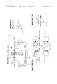
- FIG. 1 a shows a block diagram of a unidirectional optical amplifier 1 .
- an optical amplifier comprises an Erbium doped fiber amplifier (EDFA) 3 optically connected in fiber 2 using connectors 5 , for amplifying light (a channel or more) received at the input.
- EDFA 3 is powered by a light source 4 (a laser).
- a power monitor 12 receives a fraction of the input and output signals and controls accordingly the laser.
- Taps 13 and 14 divert the fraction of the signal on fiber 2 , optical-to-electrical converters 6 and 6 ′ convert the respective fractions to electrical signals, which are thereafter amplified by transimpedance amplifiers 7 and 7 ′ in the known way.
- Capacitors C 1 separate the dc component and the A/D and D/A converters 8 , 8 ′ and 9 provide the power monitor and respectively the light source with the corresponding type of signal. It is to be understood that this a general overview, the optical amplifier being in general provided with additional controls, some with analog maintenance tones, etc, which are not illustrated for simplification, and also as these functions are not relevant to the present invention.
- FIG. 1 b shows the symbol for a unidirectional optical amplifier 1 which includes gain control or transient suppression.
- the optical amplifier packages according to the invention operate in a modular manner, exploiting the entire conventional Erbium gain window, known as band C, as well as the extended Erbium gain window, known as band E.
- band C conventional Erbium gain window
- band E extended Erbium gain window
- module module
- packet package
- BB building block
- FIGS. 2 to 8 The basic modules for the new OA topologies are shown in FIGS. 2 to 8 . Since it may not be readily apparent how these various modules inter-work, a set of applications are presented in FIGS. 9 to 14 .
- the basic modules that form the MOSAIC family are:
- An extended band (e.g. 1570-1603 nm) version for each of the above amplifier circuit packs which can be used for unidirectional or bidirectional overlays or within a true bidirectional system
- a unidirectional Optical Service Channel (OSC) circuit pack which provides a means for OAM&P functionality to the optical network.
- a bidirectional OSC is also available for bidirectional systems
- IOTA Intelligent Optical Terminal Accessway
- FIG. 2 a illustrates a dual amplifier circuit package 20 according to the invention, which includes two optical amplifiers 10 and 10 ′. It is anticipated that dual nature of this circuit package will be fully exploited in the early stages of network deployment (day one), because of the demand for bidirectional flow of the traffic in modern networks.
- the dual amplifier module is manufactured in a number of versions, each for use according to a specific application.
- a C-version is for the conventional Erbium optical bandwidth
- a sister E-version spans the extended Erbium band
- a hybrid H-version which comprises both a C and an E band amplifier for use in bidirectional systems.
- the package 20 includes unidirectional amplifiers 10 , which are provided with gain control for transient suppression. This feature allows the amplifier to deal with both expected and unexpected additions or drops of one or a number of wavelengths in a WDM environment, with the ultimate goal of maintaining the original wavelengths unperturbed.
- the amplifiers have also a low noise figure, while providing a relatively low cost entry offering while offering a platform for future scalability.
- Connectors designated by a, b, a′, b′, c, d, c′ and d′ are faceplate connectors for the Line- 1 In, Line- 1 Out, Line- 2 In, Line- 2 Out, OSC Drop 1 , OSC Add 1 , OSC Drop 2 , and OSC Add 2 , respectively.
- WDM couplers 21 are used for add/drop of the OSC channel to the input and output of each amplifier 10 , 10 ′.
- the package is provided with optical tap couplers 22 and 23 .
- Tap 22 at the input of the amplifiers, diverts a fraction from the input traffic
- tap 23 at the output of the amplifiers, is a bidirectional tap for diverting fractions from both directions.
- the signals collected at the taps are used for power monitoring, analog maintenance, equalization, testing, and reflection detection.
- FIG. 2 b illustrates the symbol for the dual optical amplifier module of FIG. 2 a.
- FIG. 3 illustrates a booster amplifier package 25 .
- These BB comprises a multiple pumped EDFA (Erbium doped fiber amplifier) 25 , which provides a substantial increase in optical output power for booster amplifier applications where large output powers are required.
- the booster amplifier package also contains an embedded variable optical attenuator (VOA) 24 for controlling the gain tilt.
- VOA optical attenuator
- the package is also provided with gain control for transient suppression, and with an output circulator 26 which acts as an output isolator as well as an upgrade port for an interleaved filter based amplifier topology as it will be seen later.
- Optical circulators use polarization properties of light and they are directional. Thus, the multichannel signal while travels within the circulator from port to port in one direction only, and channels are added and dropped at different ports.
- the amplifier 25 is also provided with taps 22 and 23 .
- the booster amplifier package family offers a booster amplifier version, a booster-plus amplifier version, a C-version and a sister E-version. The difference between the booster amplifier and the booster-plus amplifier is that the later offers significantly more output power than the former.
- FIG. 4 a illustrates a unidirectional optical service channel (OSC) module 30 which supports OAM&P capability at optical transport platform network elements.
- Module 30 is capable of accessing two OSCs, one at 1510 nm and the other at the 1480 nm.
- the package comprises a West OSC 31 , with the receiver for the first OSC and the transmitter for the second OSC.
- the East OSC 32 comprises the transmitter for the first OSC and the receiver for the second OSC.
- Each channel is accommodated on a separate fiber, so that the package comprises four faceplate connectors a and b for the first channel and a′ and b′ for the second.
- the package also comprises WDM couplers 21 for the East and West drop, used for the bidirectional OSC package.
- FIG. 4 b shows the symbol for the unidirectional OSC package.
- the OSC circuit package is also offered as a bidirectional OSC 35 with only two faceplate optical connectors a and b, for use in a true bidirectional system.
- This circuit pack is represented schematically in FIG. 5 a.
- the unidirectional OSC and bidirectional OSC circuit packages provide the amplifier group with OAM&P functionality.
- One of these packages is mandatory in the formation of an optical amplifier group and it acts as a foundation and communication port for that group.
- the OSC module does not offer protection switching of the OSC channel, but rather offers a redundant OSC channel which is running on the SONET protection path. Therefore, where SONET traffic flows so must an OSC channel.
- the OSC BBs also allow for versatile card placement of all other members of the family within a bay, since this is the only member of the family which has any slot requirements.
- FIG. 5 b illustrates the symbol for the bidirectional OSC of FIG. 5 a.
- FIG. 6 illustrates the symbol for a dispersion compensation module (DCM) 40 , which compensates for fiber dispersion.
- DCM dispersion compensation module
- FIG. 7 a illustrates an interleaved filter package 45 , which includes an even filter 46 (grid-1) and an odd filter 47 (grid-2) in the same package.
- the filter has a FSR free spectral range (FSR) of 100 GHz for 50 GHz on fiber.
- FSR FSR free spectral range
- the grid-1 46 filter supports 40 wavelengths on the 100 GHz ITU grid
- the grid-2 filter 47 supports another 40 wavelengths offset by 50 GHz.
- This BB family comprises a C-variant and a sister E-variant, including a pair of filters for the E band.
- the filter packages 45 are provided with performance monitoring through analog maintenance (AM), whereby each channel carries its unique identification.
- AM analog maintenance
- FIG. 7 b illustrates the symbol for a filter 46 or 47 of FIG. 7 a.
- FIGS. 8 a and 8 b illustrate the symbol for the intelligent optical terminal accessway (IOTA).
- This family of BBs provides termination access to a network replacing the current passive filter multiplexer/demultiplexer solution. It consists of three circuit packages, a multiplexer 50 , a demultiplexer 55 and a controller 60 .
- the multiplexer circuit package 50 provides individual transmitter inputs a-d. Each input has a power monitor and controlled VOA capability (not shown).
- An internal filter 51 multiplexes all transmitter inputs onto a single output.
- the demultiplexer circuit package 55 provides individual receiver outputs a′-d′.
- An internal filter 56 demultiplexes the single fiber input onto the individual outputs.
- Controller circuit package 65 provides communication to the network via OSC, and operates as a controller for the three circuit packages. The controller 65 includes AM monitoring of the multiplexer output.
- the multiplexer 50 , demultiplexer 55 and controller 60 packages can communicate to the other IOTA circuit packages.
- FIGS. 2-9 are designed as global transport products, and are therefore compatible with both SONET and SDH standards. Any discussion of SONET OC-N interfaces in this specification also implies references to SDH STM-N/3 interfaces.
- the modules shown in FIGS. 2-9 maintain the same level of compatibility with the existing Applicant's products of S/DMS TransportNodeTM OC-48 and S/DMS TransportNodeTM OC-192 families, and some compatibility with the bidirectional multiwavelength OC-192 optical amplifier (MOR) currently produced by the applicant.
- MOR bidirectional multiwavelength OC-192 optical amplifier
- existing MOR system can benefit with E-band upgrades.
- the family of modules described in connection with FIGS. 2-9 offers the network providers with the opportunity to evolve a network from an initial simple configuration of a relative low cost to more complex configurations.
- FIGS. 9 a , 9 b and 9 c illustrate line amplifier configurations.
- a line amplifier configuration there is no electrical regeneration of the SONET signal and visibility to this network element can only be achieved through the OAM&P capabilities of the OSC, or via an independent Ethernet link to the respective NE.
- dispersion compensation techniques, wavelength equalization, or add/drop multiplexing can be employed without affecting overall link performance
- FIG. 9 a illustrates the lowest cost implementation of a line amplifier site with just employing the dual amplifier module 20 and a unidirectional OSC module 30 .
- Module 30 is connected with ports e and f to the add/drop ports c, d of the dual amplifier BB 20 .
- the receiver of the OSC West 31 receives the first OSC dropped at the West input of dual amplifier 20
- the transmitter of the East OSC module 52 inserts the first OSC channel at the East output of the dual amplifier BB 20 .
- Module 30 is also connected with ports e′ and f′ to the add/drop ports c′, d′ of the dual amplifier BB 20 .
- the receiver of the OSC East 32 receives the second OSC dropped at the East input of dual amplifier 20
- the transmitter of the West OSC module 51 inserts the second OSC channel at the Weast output of the dual amplifier BB 20 .
- FIG. 9 b illustrates a second line amplifier configuration (LA- 2 ), which is a direct upgrade of configuration LA- 1 .
- Configuration LA- 2 is used when there is a need to increase the number of wavelengths, and therefore the launch power, by including booster amplifiers 25 and 25 ′ at a respective East and West output. Different levels (number of pumps) of booster amps can be added, depending on the new number of wavelengths to be supported.
- the connections for the drop side of the dual amplifier 20 (c-e and c′-e′) remain unchanged.
- the OSC 30 must now be added at a different point, i.e. at the output of the respective booster amplifier, as shown by connections f′-i′ and f-i.
- FIG. 9 c illustrates a third line amplifier configuration (LA- 3 ), which utilizes the mid-stage access capability in the configuration of FIG. 9 b.
- One use for midstage access is dispersion compensation.
- DCMs 40 and 40 ′ could be connected at the output of each line, before the respective booster amplifier 25 and 25 ′. More precisely, DCM 40 is inserted between b and g, and DCM 40 ′ is inserted between b′ and 9 ′. In this case, for the add side, the transmitters of the OSC BB 30 are connected to ports i and i′ of the respective booster amplifier 25 , 25 ′.
- booster plus amplifier could also be employed as a substitution of, or an augmentation of the booster amplifier that is illustrated in FIG. 9 c.
- FIGS. 10 a and 10 b Further upgrades of the line amplifier configurations are shown in FIGS. 10 a and 10 b, which illustrate how the E-band modules are integrated with the C-band modules to produce unidirectional or bidirectional topologies in order to scale an existing network.
- FIG. 10 a Such a configuration is shown in FIG. 10 a , where a dual C-band amplifier BB 20 - 1 is connected in parallel to an E-band dual amplifier BB 20 - 2 . Namely, the multichannel signal received at West input port a of amplifier 20 - 1 is separated into channels in C-band and in E-band. Amplifier 20 - 1 amplifies the C-band channels. The channels at output b 1 of the amplifier 20 - 1 are further boosted by booster amplifier BB 25 - 1 .
- amplifier 20 - 2 amplifies the E-band channels, which are further boosted by booster amplifier BB 25 - 2 connected at the output b 2 of the amplifier 20 - 2 .
- the C-band and E-band channels of the second line are processed in a similar way.
- the booster amplifiers at a respective East and West output are connected in series. Namely, port h 2 is connected with port i 1 so that the C-band boosted output is added with the E-band boosted output to obtain the output on the first line. Port h′′ is connected with port i′ so that the C-band boosted output is added with the E-band boosted output to obtain the output on the second line.
- the unidirectional OSC BB 30 is connected at the drop ports of the E-band amplifier, and at the add ports of the respective booster amplifiers 25 - 2 and 25 ′- 2 , i.e the OSCs are processed by the E-band equipment.
- FIG. 10 b illustrates a C and E-band dual amplifier BB 20 in a bidirectional amplifier overlay.
- Port a of dual amplifier BB 20 is the input for the C-band channels and the output for the E-band channels, while port h of booster 25 is the input for the E-band channels and the output for the C-band channels.
- FIG. 10 b The configuration of FIG. 10 b is also provided with booster amplifiers 25 and 25 ′, for allowing bidirectional amplification of a large number of channels.
- the booster amplifier BBs are connected as in the previous cases at the output of the respective amplifier.
- BiOSC module 35 needs to be used, since only one fiber is available for the working channel.
- BiOSC is processed with the E-band channels.
- the bidirectional amplified system of FIGS. 10 a and 10 b is based on a band segmentation scheme.
- a band segmentation scheme is implemented by the dissection of an otherwise continuous optical bandwidth into two or more sub-bands.
- the sub-bands are then amplified and/or compensated separately and therefore independently.
- the inherent drawback of a band segmentation scheme is an unusable dead band, which acts as a guard band, between each of the sub-bands therefore wasting optical bandwidth.
- Another option for deploying dense WDM systems in a bidirectional system is to transmit an interleaved set of channels.
- every other optical channel on a 50 GHz grid travels in one direction, while the remaining channels travel in the opposite direction.
- the advantage of this technique is that it allows for 100 GHz channel spacing in any one direction, and does not suffer from any dead band, which is inevitably imposed by a band segmentation.
- FIG. 11 a illustrates a bidirectional amplifier topology using interleaved filters.
- the main fiber 2 - 2 ′ carries the grid-1 channels in the West-to-East direction and the grid-2 channels in East-to-West direction.
- a booster 25 - 2 is connected to the West fiber 2 and a booster 25 - 1 is connected to the East fiber 2 ′.
- Circulator of booster 25 - 2 separates the channels according to their direction.
- the grid-1 channels are output at port j′ and directed to a C-dual amplifier BB 20 , that amplifies channels presented to port a and output them at port b.
- a grid-1 filter 45 is connected between the East output of amplifier 20 and booster 25 - 1 , for attenuating any grid-2 channels and transmitting grid-1 channels.
- Booster amplifier 25 - 1 provides the boosted grid-1 channels on fiber 2 ′.
- the dual amplifier 20 in this configuration is a C-band amplifier.
- circulator of booster 25 - 1 directs the all grid-2 channels to East port b of dual amplifier BB 20 , that amplifies these channels and present them at output port b′.
- a grid-1 filter 50 is connected between the West output of amplifier 20 and booster 25 - 2 , for attenuating any grid-1 channels and transmitting grid-2 channels.
- Booster amplifier 25 - 2 provides the boosted grid-2 channels on fiber 2 .
- the OSC channels for bidirectional OSC 35 are added/dropped as discussed above.
- Interleaved filters can also be used in the E-band, and in the C-band as illustrated in FIG. 11 b. This configuration provides for the highest capacity optical amplifier group.
- the C-band channels are treated separately from the e-band channels.
- booster 25 ′- 1 , grid-2 filter 50 - 1 , dual amplifier 20 - 1 , grid-1 filter 45 - 1 and booster amplifier 25 - 1 are provided for C-band channels
- booster 25 ′- 2 , grid-2 filter 50 - 2 , dual amplifier 20 - 2 , grid-1 filter 45 - 2 and booster amplifier 25 - 2 are provided for E-band channels. Separation of grid-1 and grid-2 channels from the main signal on fiber 2 , 2 ′ is made, for each band, by the circulators of the respective booster amplifiers.
- FIG. 12 a illustrates a first line terminating equipment configuration (LTE- 1 ) for optical amplification at a line terminating equipment (LTE) site.
- the LTE node comprises a multiplexer 50 for combining four channels in the West-to-East direction, a demultiplexer 55 for separating four channels in the East-to-West direction, and a dual amplifier BB 20 .
- Dual amplifier BB 20 is used as a post-amplifier placed before the East-bound signals are launched over fiber 2 , and as a preamplifier for the East-bound signals.
- An OSC 30 is connected at add/drop ports d and c′.
- This configuration offers a low cost entry solution for optical amplification at LTE sites.
- the working channel implementation is illustrated using four wavelengths for illustrative purposes only. The actual number of wavelengths can be more than 8 in each direction.
- the configuration may be upgraded by adding booster amplifiers at the outputs of the dula amplifier, as shown with arrows.
- FIG. 12 b illustrates a second configuration LTE- 2 which is an upgrade of LTE- 1 .
- This configuration has the advantage of launching more optical power from the transmitter side than the previous configuration by adding a booster amplifier 30 to the existing dual amplifier 20 . This would increase the number of wavelengths the system can accommodate.
- FIG. 12 c illustrates a third configuration LTE- 3 , with an intelligent optical terminal accessway (IOTA) controller 60 .
- the controller 60 is connected between the multiplexer 55 and port a of the dual amplifier BB 20 .
- IOTA 60 is also connected to OSC West of the BB 30 , for communication with other nodes of the network.
- different power (different number of pumps) booster amplifiers can be used instead, depending on the power requirements.
- FIG. 13 illustrates an upgrade for an existing multiwavelength optical amplifier MOR 15 .
- the MOR amplifier 15 can be upgraded with some modules provided herein, in particular with an E-band dual amplifier 20 .
- the OSC 36 of the MOR system should be used as the data communication channel.
- the modules may reside in a separate bay and may be connect via Ethernet to the MOR 15 bay so that the modules have network visibility.
- FIG. 14 illustrates a configuration ST- 1 for optical amplification at a section terminating equipment (STE) 36 .
- the site comprises a West multiplexer/demultiplexer, a regenerator and a East multiplexer/demultiplexer.
- the upgrade comprises adding a West dual amplifier 20 - 1 and an East dual amplifier 20 - 2 , each connected to a respective unidirectional OSC 30 - 1 and 30 - 2 . This is a low cost configuration, which can be further upgraded to include booster amplifiers.
Abstract
Description
Claims (30)
Priority Applications (8)
| Application Number | Priority Date | Filing Date | Title |
|---|---|---|---|
| US09/292,340 US6236499B1 (en) | 1999-04-15 | 1999-04-15 | Highly scalable modular optical amplifier based subsystem |
| PCT/CA2000/000121 WO2000064079A1 (en) | 1999-04-15 | 2000-02-10 | A highly scalable modular optical amplifier based subsystem |
| EP00903457A EP1183801B1 (en) | 1999-04-15 | 2000-02-10 | A highly scalable modular optical amplifier based subsystem |
| CA2369754A CA2369754C (en) | 1999-04-15 | 2000-02-10 | A highly scalable modular optical amplifier based subsystem |
| AT00903457T ATE332596T1 (en) | 1999-04-15 | 2000-02-10 | HIGHLY SCALABLE MODULAR OPTICAL AMPLIFIER SUBSYSTEM |
| AU25293/00A AU2529300A (en) | 1999-04-15 | 2000-02-10 | A highly scalable modular optical amplifier based subsystem |
| DE60029220T DE60029220T2 (en) | 1999-04-15 | 2000-02-10 | HIGH-SCALE MODULAR OPTICAL AMPLIFIER PARTIAL SYSTEM |
| US09/817,753 US6757098B2 (en) | 1999-04-15 | 2001-03-27 | Highly scalable modular optical amplifier based subsystem |
Applications Claiming Priority (1)
| Application Number | Priority Date | Filing Date | Title |
|---|---|---|---|
| US09/292,340 US6236499B1 (en) | 1999-04-15 | 1999-04-15 | Highly scalable modular optical amplifier based subsystem |
Related Child Applications (1)
| Application Number | Title | Priority Date | Filing Date |
|---|---|---|---|
| US09/817,753 Continuation-In-Part US6757098B2 (en) | 1999-04-15 | 2001-03-27 | Highly scalable modular optical amplifier based subsystem |
Publications (1)
| Publication Number | Publication Date |
|---|---|
| US6236499B1 true US6236499B1 (en) | 2001-05-22 |
Family
ID=23124231
Family Applications (1)
| Application Number | Title | Priority Date | Filing Date |
|---|---|---|---|
| US09/292,340 Expired - Lifetime US6236499B1 (en) | 1999-04-15 | 1999-04-15 | Highly scalable modular optical amplifier based subsystem |
Country Status (7)
| Country | Link |
|---|---|
| US (1) | US6236499B1 (en) |
| EP (1) | EP1183801B1 (en) |
| AT (1) | ATE332596T1 (en) |
| AU (1) | AU2529300A (en) |
| CA (1) | CA2369754C (en) |
| DE (1) | DE60029220T2 (en) |
| WO (1) | WO2000064079A1 (en) |
Cited By (74)
| Publication number | Priority date | Publication date | Assignee | Title |
|---|---|---|---|---|
| WO2001082516A1 (en) * | 2000-04-24 | 2001-11-01 | Lucent Technologies Inc. | Gain equalization in dwdm networks |
| US6339663B1 (en) * | 2000-12-22 | 2002-01-15 | Seneca Networks, Inc. | Bidirectional WDM optical communication system with bidirectional optical service channels |
| US6341034B1 (en) | 2000-10-18 | 2002-01-22 | Onetta Inc. | Optical amplifier system with transient control using spectrally filtered input |
| US6414788B1 (en) | 2000-10-02 | 2002-07-02 | Onetta, Inc. | Optical amplifier system with transient control |
| US6441950B1 (en) | 2000-11-03 | 2002-08-27 | Onetta, Inc. | Distributed raman amplifier systems with transient control |
| US6476961B1 (en) | 2001-04-26 | 2002-11-05 | Onetta, Inc. | Optical amplifier systems with transient control |
| US6498677B1 (en) | 2000-10-23 | 2002-12-24 | Onetta, Inc. | Optical amplifier systems with transient control |
| US20020196528A1 (en) * | 1996-06-26 | 2002-12-26 | Jolley Nigel Edward | Optical amplifier modules |
| US6542661B2 (en) * | 2001-04-06 | 2003-04-01 | Corning Incorporated | Method for upgrading bandwidth in an optical system utilizing Raman amplification |
| US6542287B1 (en) | 2000-12-12 | 2003-04-01 | Onetta, Inc. | Optical amplifier systems with transient control |
| US20030063345A1 (en) * | 2001-10-01 | 2003-04-03 | Dan Fossum | Wayside user communications over optical supervisory channel |
| WO2003030427A1 (en) * | 2001-10-03 | 2003-04-10 | Tejas Networks India Pvt. Ltd. | Improving osnr of optically amplified dwdm transmission system |
| WO2003030428A1 (en) * | 2001-10-03 | 2003-04-10 | Tejas Networks India Pvt. Ltd. | System for improving osnr of dwdm transmission system |
| US6556340B1 (en) | 2001-04-06 | 2003-04-29 | Onetta, Inc. | Optical amplifiers and upgrade modules |
| US6560008B1 (en) * | 1999-11-16 | 2003-05-06 | Fujitsu Limited | Controlling apparatus and controlling method for wavelength division multiplexing optical amplifier |
| US20030184846A1 (en) * | 2002-03-27 | 2003-10-02 | Bennett Kevin W. | Modular optical amplifier assembly and a method of assembly |
| US20030185486A1 (en) * | 2002-03-27 | 2003-10-02 | Bennett Kevin W. | Optical amplification module |
| US20030185485A1 (en) * | 2002-03-27 | 2003-10-02 | Bennett Kevin W. | Optical processing module |
| US20030185518A1 (en) * | 2002-03-27 | 2003-10-02 | Bennett Kevin W. | Customer interface module |
| US20030185483A1 (en) * | 2002-03-27 | 2003-10-02 | Bennett Kevin W. | Optical monitoring and access module |
| US20030203721A1 (en) * | 2002-04-25 | 2003-10-30 | Raytheon Company | Adaptive air interface waveform |
| US20030206335A1 (en) * | 2002-05-03 | 2003-11-06 | Lightwaves 2020, Inc. | Erbium-doped fiber amplifier and integrated module components |
| WO2003094398A1 (en) * | 2002-04-30 | 2003-11-13 | Celion Networks, Inc. | Optical transport system architecture for remote terminal connectivity |
| US20030219255A1 (en) * | 2002-03-29 | 2003-11-27 | Pawan Jaggi | Distributed terminal optical transmission system |
| KR100407346B1 (en) * | 2001-10-12 | 2003-11-28 | 삼성전자주식회사 | Semiconductor optical amplifier with monitoring device |
| US20030223682A1 (en) * | 2002-05-30 | 2003-12-04 | Susumu Kinoshita | Optical add/drop node and method |
| US20030223683A1 (en) * | 2002-03-27 | 2003-12-04 | Bennett Kevin W. | Modular optical amplifier assembly |
| US20030228148A1 (en) * | 2002-06-11 | 2003-12-11 | Fujitsu Limited | Optical ring network system having a plurality of node apparatuses connected in a ring |
| US6665497B1 (en) | 2001-07-05 | 2003-12-16 | Cisco Technology, Inc. | Modular transceiver and accessory system for use in an optical network |
| US20030231886A1 (en) * | 2002-04-22 | 2003-12-18 | Young Marvin Ray | Automated optical transport system |
| US20030235215A1 (en) * | 2002-03-28 | 2003-12-25 | Carrel John Robert | Apparatus and method for aggregation and transportation for plesiosynchronous framing oriented data formats |
| US20040001717A1 (en) * | 2002-03-27 | 2004-01-01 | Bennett Kevin W. | Optical power supply module |
| US20040013435A1 (en) * | 2002-04-30 | 2004-01-22 | Eiselt Michael H. | Apparatus and method for optimizing optical and electrical filtering of optical signals |
| US20040017602A1 (en) * | 2002-03-27 | 2004-01-29 | Bennett Kevin W. | Modular optical amplifier assembly with self identifying modules |
| US6690505B1 (en) | 2001-09-28 | 2004-02-10 | Onetta, Inc. | Optical network equipment with gain transient control and automatic drift compensation |
| US20040028408A1 (en) * | 2002-04-08 | 2004-02-12 | Cox Jeffrey Lloyd | Apparatus and method for transmitting 10 Gigabit Ethernet LAN signals over a transport system |
| US20040028415A1 (en) * | 2002-04-30 | 2004-02-12 | Eiselt Michael H. | Apparatus and method for measuring the dispersion of a fiber span |
| US20040028323A1 (en) * | 2002-03-27 | 2004-02-12 | Bennett Kevin W | Telemetry add/drop module |
| US20040033080A1 (en) * | 2002-04-30 | 2004-02-19 | Eiselt Michael H. | Wave division multiplexed optical transport system utilizing optical circulators to isolate an optical service channel |
| US20040033079A1 (en) * | 2002-06-04 | 2004-02-19 | Sheth Samir Satish | Flexible, dense line card architecture |
| US20040032645A1 (en) * | 1999-10-29 | 2004-02-19 | Fujitsu Limited | Optical transmitting apparatus and optical repeating apparatus |
| US20040042067A1 (en) * | 2002-06-04 | 2004-03-04 | Eiselt Michael H. | Apparatus and method for duplex optical transport using a co-directional optical amplifier |
| US20040042068A1 (en) * | 2002-06-04 | 2004-03-04 | Eiselt Michael H. | Apparatus and method for Raman gain spectral control |
| US20040047550A1 (en) * | 2002-06-04 | 2004-03-11 | Bo Guo | Configurable dispersion compensation trimmer |
| US20040070805A1 (en) * | 2002-06-04 | 2004-04-15 | Eiselt Michael H. | Apparatus and method for optimum decision threshold setting |
| US20040075888A1 (en) * | 2002-04-30 | 2004-04-22 | Eiselt Michael H. | Compensation for spectral power tilt from scattering |
| US20040075887A1 (en) * | 2002-06-04 | 2004-04-22 | Eiselt Michael H. | Apparatus and method for raman gain control |
| US6731830B2 (en) * | 2001-01-05 | 2004-05-04 | Redfern Broadband Networks, Inc. | Asymmetric compatible network element |
| US20040175187A1 (en) * | 2002-12-13 | 2004-09-09 | Eiselt Michael H. | Single fiber duplex optical transport |
| US20040208522A1 (en) * | 2001-11-08 | 2004-10-21 | Ian Dawes | Optical media management channel |
| US20040212875A1 (en) * | 2002-01-30 | 2004-10-28 | Jinghui Li | Integrated optical dual amplifier |
| US20040223210A1 (en) * | 2002-10-09 | 2004-11-11 | Eci Telecom Ltd. | Two stage optical amplifier |
| US20040240783A1 (en) * | 2003-05-30 | 2004-12-02 | Junnarkar Mahesh R. | Monitoring power in optical networks |
| US6839163B1 (en) | 1999-09-01 | 2005-01-04 | Avanex Corporation | Apparatus and method for making an optical fiber amplifier |
| US6888671B2 (en) * | 2001-04-02 | 2005-05-03 | Samsung Electronics Co., Ltd. | Optical amplifier device and bidirectional wavelength division multiplexing optical communication system using the same |
| US6920277B2 (en) | 2002-06-04 | 2005-07-19 | Marvin R. Young | Optical bypass method and architecture |
| US20050163168A1 (en) * | 2002-12-24 | 2005-07-28 | Sheth Samir S. | Apparatus and method for fibre channel distance extension embedded within an optical transport system |
| US20050226630A1 (en) * | 2003-06-03 | 2005-10-13 | Celion Networks Inc. | Optical bypass method and architecture |
| US20060045528A1 (en) * | 2004-08-27 | 2006-03-02 | Fujitsu Network Communications, Inc. | System and method for modularly scalable architecture for optical networks |
| US20060127099A1 (en) * | 2002-04-16 | 2006-06-15 | Celion Networks, Inc. | Chromatic dispersion compensation system and method |
| US7076163B2 (en) | 2002-03-27 | 2006-07-11 | Fujitsu Limited | Method and system for testing during operation of an open ring optical network |
| US7116905B2 (en) | 2002-03-27 | 2006-10-03 | Fujitsu Limited | Method and system for control signaling in an open ring optical network |
| US7231148B2 (en) | 2002-03-28 | 2007-06-12 | Fujitsu Limited | Flexible open ring optical network and method |
| US7286756B1 (en) * | 2001-05-15 | 2007-10-23 | Cisco Technology, Inc. | DWDM system with IP telephony provisioning at remote locations |
| AU2003222271B2 (en) * | 2002-05-06 | 2008-03-06 | Cisco Technology, Inc. | VoIP service over an ethernet network carried by a DWDM optical supervisory channel |
| US7343096B1 (en) * | 2003-06-18 | 2008-03-11 | Ciena Corporation | Method and apparatus for in-service upgrading of OADM to wavelength selective switch of higher degree |
| US20090028562A1 (en) * | 2006-03-06 | 2009-01-29 | Nokia Siemens Networks Gmbh & Co. Kg | Bidirectional optical amplifier arrangement |
| US20090175626A1 (en) * | 2008-01-03 | 2009-07-09 | Dan Yang | Optical transceiver amplifier |
| US7656905B2 (en) | 2002-12-24 | 2010-02-02 | Samir Sheth | Apparatus and method for aggregation and transportation of gigabit ethernet and other packet based data formats |
| US20120087669A1 (en) * | 2010-10-07 | 2012-04-12 | Fujitsu Limited | Optical node and optical communication method |
| US10114185B2 (en) * | 2017-01-13 | 2018-10-30 | Facebook, Inc. | Submarine optical fiber communications architectures |
| US10263386B1 (en) | 2018-04-13 | 2019-04-16 | Ciena Corporation | Four-wave mixing reduction due to raman pumps in optical communication systems |
| US10411796B1 (en) | 2018-05-22 | 2019-09-10 | Ciena Corporation | Optical fiber characterization measurement systems and methods |
| US11770193B2 (en) | 2021-07-28 | 2023-09-26 | Ciena Corporation | Mitigating instability in cascaded optical power controllers |
Families Citing this family (2)
| Publication number | Priority date | Publication date | Assignee | Title |
|---|---|---|---|---|
| US6757098B2 (en) | 1999-04-15 | 2004-06-29 | Nortel Network Limited | Highly scalable modular optical amplifier based subsystem |
| CA2354446A1 (en) * | 2000-11-22 | 2002-05-22 | Blaine Hobson | An optical switch and method of switching optical signals |
Citations (12)
| Publication number | Priority date | Publication date | Assignee | Title |
|---|---|---|---|---|
| EP0440276A2 (en) | 1990-01-30 | 1991-08-07 | PIRELLI CAVI S.p.A. | Optical fibre telecommunications line with separate service channels |
| US5083874A (en) * | 1989-04-14 | 1992-01-28 | Nippon Telegraph And Telephone Corporation | Optical repeater and optical network using the same |
| US5228105A (en) * | 1987-05-04 | 1993-07-13 | Glista Andrew S | Programmable electro-optic packaging and interconnect system |
| US5742416A (en) * | 1996-03-28 | 1998-04-21 | Ciena Corp. | Bidirectional WDM optical communication systems with bidirectional optical amplifiers |
| US5748363A (en) * | 1995-11-30 | 1998-05-05 | Fitel Inc. | Wavelength dependent crossover system for bi-directional transmission |
| EP0844757A2 (en) | 1996-11-21 | 1998-05-27 | Nec Corporation | Branching system with optical add drop multiplexing function |
| US5812306A (en) * | 1996-06-14 | 1998-09-22 | Ciena Corporation | Bidirectional WDM optical communication systems with bidirectional optical amplifiers |
| WO1998049794A2 (en) | 1997-04-30 | 1998-11-05 | Telefonaktiebolaget Lm Ericsson (Publ) | Low loss, optical add/drop wdm node |
| WO1998052314A2 (en) | 1997-05-15 | 1998-11-19 | Telefonaktiebolaget Lm Ericsson (Publ) | An add and drop node for optical communication systems |
| US5959749A (en) * | 1998-05-20 | 1999-09-28 | Nortel Networks Corporation | Optical add/drop multiplexer/demultiplexer |
| US5995259A (en) * | 1995-01-27 | 1999-11-30 | Pirelli Cavi S.P.A. | Bidirectional optical telecommunication system comprising a bidirectional optical amplifier |
| US6055092A (en) * | 1995-03-09 | 2000-04-25 | Fujitsu Limited | Multi-wavelength light amplifier |
-
1999
- 1999-04-15 US US09/292,340 patent/US6236499B1/en not_active Expired - Lifetime
-
2000
- 2000-02-10 AT AT00903457T patent/ATE332596T1/en not_active IP Right Cessation
- 2000-02-10 WO PCT/CA2000/000121 patent/WO2000064079A1/en active IP Right Grant
- 2000-02-10 AU AU25293/00A patent/AU2529300A/en not_active Abandoned
- 2000-02-10 EP EP00903457A patent/EP1183801B1/en not_active Expired - Lifetime
- 2000-02-10 DE DE60029220T patent/DE60029220T2/en not_active Expired - Lifetime
- 2000-02-10 CA CA2369754A patent/CA2369754C/en not_active Expired - Lifetime
Patent Citations (15)
| Publication number | Priority date | Publication date | Assignee | Title |
|---|---|---|---|---|
| US5228105A (en) * | 1987-05-04 | 1993-07-13 | Glista Andrew S | Programmable electro-optic packaging and interconnect system |
| US5083874A (en) * | 1989-04-14 | 1992-01-28 | Nippon Telegraph And Telephone Corporation | Optical repeater and optical network using the same |
| US5113459A (en) | 1990-01-30 | 1992-05-12 | Pirelli Cavi S.P.A. | Optical fiber telecommunication line with separate, optically transmitted service channels |
| EP0440276A2 (en) | 1990-01-30 | 1991-08-07 | PIRELLI CAVI S.p.A. | Optical fibre telecommunications line with separate service channels |
| US5113459C1 (en) | 1990-01-30 | 2001-10-23 | Pirelli Cavi Spa | Optical fiber telecommunication line with separate optically transmitted service channels |
| US5995259A (en) * | 1995-01-27 | 1999-11-30 | Pirelli Cavi S.P.A. | Bidirectional optical telecommunication system comprising a bidirectional optical amplifier |
| US6055092A (en) * | 1995-03-09 | 2000-04-25 | Fujitsu Limited | Multi-wavelength light amplifier |
| US5748363A (en) * | 1995-11-30 | 1998-05-05 | Fitel Inc. | Wavelength dependent crossover system for bi-directional transmission |
| US5742416A (en) * | 1996-03-28 | 1998-04-21 | Ciena Corp. | Bidirectional WDM optical communication systems with bidirectional optical amplifiers |
| US5812306A (en) * | 1996-06-14 | 1998-09-22 | Ciena Corporation | Bidirectional WDM optical communication systems with bidirectional optical amplifiers |
| EP0844757A2 (en) | 1996-11-21 | 1998-05-27 | Nec Corporation | Branching system with optical add drop multiplexing function |
| US6038046A (en) | 1996-11-21 | 2000-03-14 | Nec Corporation | Branching system with optical add drop multiplexing function |
| WO1998049794A2 (en) | 1997-04-30 | 1998-11-05 | Telefonaktiebolaget Lm Ericsson (Publ) | Low loss, optical add/drop wdm node |
| WO1998052314A2 (en) | 1997-05-15 | 1998-11-19 | Telefonaktiebolaget Lm Ericsson (Publ) | An add and drop node for optical communication systems |
| US5959749A (en) * | 1998-05-20 | 1999-09-28 | Nortel Networks Corporation | Optical add/drop multiplexer/demultiplexer |
Cited By (150)
| Publication number | Priority date | Publication date | Assignee | Title |
|---|---|---|---|---|
| US20020196528A1 (en) * | 1996-06-26 | 2002-12-26 | Jolley Nigel Edward | Optical amplifier modules |
| US6894829B2 (en) * | 1996-06-26 | 2005-05-17 | Nortel Networks Limited | Optical amplifier modules |
| US6839163B1 (en) | 1999-09-01 | 2005-01-04 | Avanex Corporation | Apparatus and method for making an optical fiber amplifier |
| US20040032645A1 (en) * | 1999-10-29 | 2004-02-19 | Fujitsu Limited | Optical transmitting apparatus and optical repeating apparatus |
| US6924927B2 (en) * | 1999-10-29 | 2005-08-02 | Fujitsu Limited | Optical transmitting apparatus and optical repeating apparatus |
| US6870666B2 (en) | 1999-11-16 | 2005-03-22 | Fujitsu Limited | Controlling apparatus and controlling method for wavelength division multiplexing optical amplifier |
| US6560008B1 (en) * | 1999-11-16 | 2003-05-06 | Fujitsu Limited | Controlling apparatus and controlling method for wavelength division multiplexing optical amplifier |
| WO2001082516A1 (en) * | 2000-04-24 | 2001-11-01 | Lucent Technologies Inc. | Gain equalization in dwdm networks |
| US6414788B1 (en) | 2000-10-02 | 2002-07-02 | Onetta, Inc. | Optical amplifier system with transient control |
| US6341034B1 (en) | 2000-10-18 | 2002-01-22 | Onetta Inc. | Optical amplifier system with transient control using spectrally filtered input |
| US6498677B1 (en) | 2000-10-23 | 2002-12-24 | Onetta, Inc. | Optical amplifier systems with transient control |
| US6441950B1 (en) | 2000-11-03 | 2002-08-27 | Onetta, Inc. | Distributed raman amplifier systems with transient control |
| US6542287B1 (en) | 2000-12-12 | 2003-04-01 | Onetta, Inc. | Optical amplifier systems with transient control |
| US6339663B1 (en) * | 2000-12-22 | 2002-01-15 | Seneca Networks, Inc. | Bidirectional WDM optical communication system with bidirectional optical service channels |
| WO2002052317A1 (en) * | 2000-12-22 | 2002-07-04 | Seneca Networks, Inc. | Bidirectional wdm optical communication system with bidirectional optical service channels |
| US6614956B2 (en) | 2000-12-22 | 2003-09-02 | Lightrail Networks, Inc. | Bidirectional WDM optical communication system with bidirectional optical service channels |
| US6731830B2 (en) * | 2001-01-05 | 2004-05-04 | Redfern Broadband Networks, Inc. | Asymmetric compatible network element |
| US6888671B2 (en) * | 2001-04-02 | 2005-05-03 | Samsung Electronics Co., Ltd. | Optical amplifier device and bidirectional wavelength division multiplexing optical communication system using the same |
| US6556340B1 (en) | 2001-04-06 | 2003-04-29 | Onetta, Inc. | Optical amplifiers and upgrade modules |
| US6542661B2 (en) * | 2001-04-06 | 2003-04-01 | Corning Incorporated | Method for upgrading bandwidth in an optical system utilizing Raman amplification |
| US6476961B1 (en) | 2001-04-26 | 2002-11-05 | Onetta, Inc. | Optical amplifier systems with transient control |
| US7286756B1 (en) * | 2001-05-15 | 2007-10-23 | Cisco Technology, Inc. | DWDM system with IP telephony provisioning at remote locations |
| US6665497B1 (en) | 2001-07-05 | 2003-12-16 | Cisco Technology, Inc. | Modular transceiver and accessory system for use in an optical network |
| US6690505B1 (en) | 2001-09-28 | 2004-02-10 | Onetta, Inc. | Optical network equipment with gain transient control and automatic drift compensation |
| US20030063345A1 (en) * | 2001-10-01 | 2003-04-03 | Dan Fossum | Wayside user communications over optical supervisory channel |
| WO2003030428A1 (en) * | 2001-10-03 | 2003-04-10 | Tejas Networks India Pvt. Ltd. | System for improving osnr of dwdm transmission system |
| WO2003030427A1 (en) * | 2001-10-03 | 2003-04-10 | Tejas Networks India Pvt. Ltd. | Improving osnr of optically amplified dwdm transmission system |
| KR100407346B1 (en) * | 2001-10-12 | 2003-11-28 | 삼성전자주식회사 | Semiconductor optical amplifier with monitoring device |
| US7146101B2 (en) | 2001-11-08 | 2006-12-05 | Altera Corporation | Optical media management channel |
| US20040208522A1 (en) * | 2001-11-08 | 2004-10-21 | Ian Dawes | Optical media management channel |
| US7460298B2 (en) * | 2002-01-30 | 2008-12-02 | Oplink Communications, Inc. | Integrated optical dual amplifier |
| US20040212875A1 (en) * | 2002-01-30 | 2004-10-28 | Jinghui Li | Integrated optical dual amplifier |
| US7076163B2 (en) | 2002-03-27 | 2006-07-11 | Fujitsu Limited | Method and system for testing during operation of an open ring optical network |
| US6917731B2 (en) | 2002-03-27 | 2005-07-12 | Corning Incorporated | Optical amplification module |
| US20040001717A1 (en) * | 2002-03-27 | 2004-01-01 | Bennett Kevin W. | Optical power supply module |
| US20030185518A1 (en) * | 2002-03-27 | 2003-10-02 | Bennett Kevin W. | Customer interface module |
| US20040017602A1 (en) * | 2002-03-27 | 2004-01-29 | Bennett Kevin W. | Modular optical amplifier assembly with self identifying modules |
| US20030185485A1 (en) * | 2002-03-27 | 2003-10-02 | Bennett Kevin W. | Optical processing module |
| US6937385B2 (en) | 2002-03-27 | 2005-08-30 | Avanex Corporation | Customer interface module |
| US20030185483A1 (en) * | 2002-03-27 | 2003-10-02 | Bennett Kevin W. | Optical monitoring and access module |
| US7116905B2 (en) | 2002-03-27 | 2006-10-03 | Fujitsu Limited | Method and system for control signaling in an open ring optical network |
| US20040028323A1 (en) * | 2002-03-27 | 2004-02-12 | Bennett Kevin W | Telemetry add/drop module |
| US20070206493A1 (en) * | 2002-03-27 | 2007-09-06 | Fujitsu Limited | Flexible Open Ring Optical Network and Method |
| US20070223371A1 (en) * | 2002-03-27 | 2007-09-27 | Fujitsu Limited | Flexible Open Ring Optical Network and Method |
| US20030185486A1 (en) * | 2002-03-27 | 2003-10-02 | Bennett Kevin W. | Optical amplification module |
| US20030184846A1 (en) * | 2002-03-27 | 2003-10-02 | Bennett Kevin W. | Modular optical amplifier assembly and a method of assembly |
| US7970278B2 (en) | 2002-03-27 | 2011-06-28 | Fujitsu Limited | Flexible open ring optical network and method |
| US7957644B2 (en) | 2002-03-27 | 2011-06-07 | Fujitsu Limited | Flexible open ring optical network and method |
| US20030223683A1 (en) * | 2002-03-27 | 2003-12-04 | Bennett Kevin W. | Modular optical amplifier assembly |
| US20030235215A1 (en) * | 2002-03-28 | 2003-12-25 | Carrel John Robert | Apparatus and method for aggregation and transportation for plesiosynchronous framing oriented data formats |
| US7231148B2 (en) | 2002-03-28 | 2007-06-12 | Fujitsu Limited | Flexible open ring optical network and method |
| USRE44015E1 (en) | 2002-03-29 | 2013-02-19 | Pivotal Decisions Llc | Distributed terminal optical transmission system |
| USRE45104E1 (en) | 2002-03-29 | 2014-09-02 | Pivotal Decisions Llc | Distributed terminal optical transmission system |
| US20090129774A1 (en) * | 2002-03-29 | 2009-05-21 | Pivotal Decisions, Llc | Distributed Terminal Optical Transmission System |
| US7505687B2 (en) | 2002-03-29 | 2009-03-17 | Pivotal Decisions Llc | Distributed terminal optical transmission system |
| US7796886B2 (en) | 2002-03-29 | 2010-09-14 | Pawan Jaggi | Distributed terminal optical transmission system |
| US7502562B2 (en) | 2002-03-29 | 2009-03-10 | Pivotal Decisions Llc | Distributed terminal optical transmission system |
| US20070104489A1 (en) * | 2002-03-29 | 2007-05-10 | Pivotal Decisions, Llc | Distributed terminal optical transmission system |
| US20030219255A1 (en) * | 2002-03-29 | 2003-11-27 | Pawan Jaggi | Distributed terminal optical transmission system |
| USRE43403E1 (en) * | 2002-03-29 | 2012-05-22 | Pivotal Decisions Llc | Distributed terminal optical transmission system |
| US20040028408A1 (en) * | 2002-04-08 | 2004-02-12 | Cox Jeffrey Lloyd | Apparatus and method for transmitting 10 Gigabit Ethernet LAN signals over a transport system |
| US7164692B2 (en) | 2002-04-08 | 2007-01-16 | Jeffrey Lloyd Cox | Apparatus and method for transmitting 10 Gigabit Ethernet LAN signals over a transport system |
| US9031092B2 (en) | 2002-04-08 | 2015-05-12 | Pivotal Decisions Llc | Apparatus and method for transmitting LAN signals over a transport system |
| US8638814B2 (en) | 2002-04-08 | 2014-01-28 | Pivotal Decisions Llc | Apparatus and method for transmitting LAN signals over a transport system |
| US8223795B2 (en) | 2002-04-08 | 2012-07-17 | Pivotal Decisions Llc | Apparatus and method for transmitting LAN signals over a transport system |
| US20060002419A1 (en) * | 2002-04-08 | 2006-01-05 | Cox Jeffrey L | Apparatus and method for transmitting 10 Gigabit Ethernet LAN signals over a transport system |
| US20070122158A1 (en) * | 2002-04-16 | 2007-05-31 | Celion Networks, Inc. | Chromatic dispersion compensation system and method |
| US8175464B2 (en) | 2002-04-16 | 2012-05-08 | Pivotal Decisions Llc | Chromatic dispersion compensation system and method |
| US20060127099A1 (en) * | 2002-04-16 | 2006-06-15 | Celion Networks, Inc. | Chromatic dispersion compensation system and method |
| US20080226302A1 (en) * | 2002-04-16 | 2008-09-18 | Pivotal Decisions Llc | Chromatic dispersion compensation system and method |
| US7725042B2 (en) | 2002-04-22 | 2010-05-25 | Marvin Ray Young | Automated optical transport system |
| US20030231886A1 (en) * | 2002-04-22 | 2003-12-18 | Young Marvin Ray | Automated optical transport system |
| US20060291859A1 (en) * | 2002-04-22 | 2006-12-28 | Pivotal Decisions, Llc | Automated optical transport system |
| US7697842B2 (en) | 2002-04-22 | 2010-04-13 | Marvin Ray Young | Automated optical transport system |
| US20030203721A1 (en) * | 2002-04-25 | 2003-10-30 | Raytheon Company | Adaptive air interface waveform |
| US20100021159A1 (en) * | 2002-04-30 | 2010-01-28 | Angela Chiu | Optical transport system architecture for remote terminal connectivity |
| US7460296B2 (en) | 2002-04-30 | 2008-12-02 | Pivotal Decisions Llc | Compensation for spectral power tilt from scattering |
| US7711271B2 (en) * | 2002-04-30 | 2010-05-04 | Eiselt Michael H | Wave division multiplexed optical transport system utilizing optical circulators to isolate an optical service channel |
| US20040028415A1 (en) * | 2002-04-30 | 2004-02-12 | Eiselt Michael H. | Apparatus and method for measuring the dispersion of a fiber span |
| US8494372B2 (en) | 2002-04-30 | 2013-07-23 | Pivotal Decisions Llc | Apparatus and method for optimizing optical and electrical filtering of optical signals |
| US20040033080A1 (en) * | 2002-04-30 | 2004-02-19 | Eiselt Michael H. | Wave division multiplexed optical transport system utilizing optical circulators to isolate an optical service channel |
| US20070008612A1 (en) * | 2002-04-30 | 2007-01-11 | Pivotal Decisions Llc | Compensation for spectral power tilt from scattering |
| US8195048B2 (en) | 2002-04-30 | 2012-06-05 | Pivotal Decisions Llc | Optical transport system architecture for remote terminal connectivity |
| US20040075888A1 (en) * | 2002-04-30 | 2004-04-22 | Eiselt Michael H. | Compensation for spectral power tilt from scattering |
| US7489880B2 (en) | 2002-04-30 | 2009-02-10 | Pivotal Decisions, Llc | Apparatus and method for measuring the dispersion of a fiber span |
| US20040022545A1 (en) * | 2002-04-30 | 2004-02-05 | Angela Chiu | Optical transport system architecture for remote terminal connectivity |
| US20040013435A1 (en) * | 2002-04-30 | 2004-01-22 | Eiselt Michael H. | Apparatus and method for optimizing optical and electrical filtering of optical signals |
| US7206516B2 (en) | 2002-04-30 | 2007-04-17 | Pivotal Decisions Llc | Apparatus and method for measuring the dispersion of a fiber span |
| US20070153259A1 (en) * | 2002-04-30 | 2007-07-05 | Pivotal Decisions Llc | Apparatus and metod for measuring the dispersion of a fiber span |
| WO2003094398A1 (en) * | 2002-04-30 | 2003-11-13 | Celion Networks, Inc. | Optical transport system architecture for remote terminal connectivity |
| US7460297B2 (en) | 2002-04-30 | 2008-12-02 | Pivotal Decisions Llc | Compensation for spectral power tilt from scattering |
| US7593637B2 (en) | 2002-04-30 | 2009-09-22 | Angela Chiu | Optical transport system architecture for remote terminal connectivity |
| US20030206335A1 (en) * | 2002-05-03 | 2003-11-06 | Lightwaves 2020, Inc. | Erbium-doped fiber amplifier and integrated module components |
| US6922281B2 (en) * | 2002-05-03 | 2005-07-26 | Lightwaves 2020, Inc. | Erbium-doped fiber amplifier and integrated module components |
| AU2003222271B2 (en) * | 2002-05-06 | 2008-03-06 | Cisco Technology, Inc. | VoIP service over an ethernet network carried by a DWDM optical supervisory channel |
| US7489867B1 (en) * | 2002-05-06 | 2009-02-10 | Cisco Technology, Inc. | VoIP service over an ethernet network carried by a DWDM optical supervisory channel |
| US6842562B2 (en) | 2002-05-30 | 2005-01-11 | Fujitsu Network Communications, Inc. | Optical add/drop node and method |
| US20030223682A1 (en) * | 2002-05-30 | 2003-12-04 | Susumu Kinoshita | Optical add/drop node and method |
| US20040042068A1 (en) * | 2002-06-04 | 2004-03-04 | Eiselt Michael H. | Apparatus and method for Raman gain spectral control |
| US20040070805A1 (en) * | 2002-06-04 | 2004-04-15 | Eiselt Michael H. | Apparatus and method for optimum decision threshold setting |
| US7440164B2 (en) | 2002-06-04 | 2008-10-21 | Pivotal Decisions Llc | Apparatus and method for Raman gain spectral control |
| US7433572B2 (en) | 2002-06-04 | 2008-10-07 | Pivotal Decisions Llc | Optical bypass method and architecture |
| US7460745B2 (en) | 2002-06-04 | 2008-12-02 | Pivotal Decisions Llc | Configurable dispersion compensation trimmer |
| US20060279834A1 (en) * | 2002-06-04 | 2006-12-14 | Pivotal Decisions, Llc | Apparatus and method for Raman gain control |
| US7471858B2 (en) | 2002-06-04 | 2008-12-30 | Pivotal Decisions Llc | Configurable dispersion compensation trimmer |
| US20060285790A1 (en) * | 2002-06-04 | 2006-12-21 | Pivotal Decisions, Llc | Optical bypass method and architecture |
| US8750713B2 (en) | 2002-06-04 | 2014-06-10 | Pivotal Decisions Llc | Flexible, dense line card architecture |
| US20060291781A1 (en) * | 2002-06-04 | 2006-12-28 | Pivotal Decisions, Llc | Configurable dispersion compensation trimmer |
| US20090047012A1 (en) * | 2002-06-04 | 2009-02-19 | Pivotal Decisions Llc | Optical bypass method and architecture |
| US20070003188A1 (en) * | 2002-06-04 | 2007-01-04 | Pivotal Decisions, Llc | Configurable dispersion compensation trimmer |
| US20040033079A1 (en) * | 2002-06-04 | 2004-02-19 | Sheth Samir Satish | Flexible, dense line card architecture |
| US20040042067A1 (en) * | 2002-06-04 | 2004-03-04 | Eiselt Michael H. | Apparatus and method for duplex optical transport using a co-directional optical amplifier |
| US8155519B2 (en) | 2002-06-04 | 2012-04-10 | Pivotal Decisions Llc | Flexible, dense line card architecture |
| US7586671B2 (en) | 2002-06-04 | 2009-09-08 | Eiselt Michael H | Apparatus and method for Raman gain control |
| US7340133B2 (en) | 2002-06-04 | 2008-03-04 | Pivotal Decisions Llc | Configurable dispersion compensation trimmer |
| US7603042B2 (en) | 2002-06-04 | 2009-10-13 | Eiselt Michael H | Apparatus and method for optimum decision threshold setting |
| US20040047550A1 (en) * | 2002-06-04 | 2004-03-11 | Bo Guo | Configurable dispersion compensation trimmer |
| US7924496B2 (en) | 2002-06-04 | 2011-04-12 | Pivotal Decisions Llc | Apparatus and method for Raman gain control |
| US20040075887A1 (en) * | 2002-06-04 | 2004-04-22 | Eiselt Michael H. | Apparatus and method for raman gain control |
| US7697802B2 (en) | 2002-06-04 | 2010-04-13 | Young Marvin R | Optical bypass method and architecture |
| US6920277B2 (en) | 2002-06-04 | 2005-07-19 | Marvin R. Young | Optical bypass method and architecture |
| US20100241913A1 (en) * | 2002-06-04 | 2010-09-23 | Samir Satish Sheth | Flexible, dense line card architecture |
| US7729617B2 (en) | 2002-06-04 | 2010-06-01 | Samir Satish Sheth | Flexible, dense line card architecture |
| EP1372281A2 (en) * | 2002-06-11 | 2003-12-17 | Fujitsu Limited | Optical ring network system having a plurality of node apparatuses connected in a ring |
| EP1372281A3 (en) * | 2002-06-11 | 2005-02-09 | Fujitsu Limited | Optical ring network system having a plurality of node apparatuses connected in a ring |
| US20030228148A1 (en) * | 2002-06-11 | 2003-12-11 | Fujitsu Limited | Optical ring network system having a plurality of node apparatuses connected in a ring |
| US20040223210A1 (en) * | 2002-10-09 | 2004-11-11 | Eci Telecom Ltd. | Two stage optical amplifier |
| US7199921B2 (en) * | 2002-10-09 | 2007-04-03 | Eci Telecom Ltd. | Two stage optical amplifier |
| US7840139B2 (en) | 2002-12-13 | 2010-11-23 | Eiselt Michael H | Single fiber duplex optical transport |
| US7421207B2 (en) | 2002-12-13 | 2008-09-02 | Pivotal Decisions Llc | Single fiber duplex optical transport |
| US20040175187A1 (en) * | 2002-12-13 | 2004-09-09 | Eiselt Michael H. | Single fiber duplex optical transport |
| US7656905B2 (en) | 2002-12-24 | 2010-02-02 | Samir Sheth | Apparatus and method for aggregation and transportation of gigabit ethernet and other packet based data formats |
| US7782778B2 (en) | 2002-12-24 | 2010-08-24 | Samir Satish Sheth | Apparatus and method for fibre channel distance extension embedded within an optical transport system |
| US20050163168A1 (en) * | 2002-12-24 | 2005-07-28 | Sheth Samir S. | Apparatus and method for fibre channel distance extension embedded within an optical transport system |
| US20040240783A1 (en) * | 2003-05-30 | 2004-12-02 | Junnarkar Mahesh R. | Monitoring power in optical networks |
| US20050226630A1 (en) * | 2003-06-03 | 2005-10-13 | Celion Networks Inc. | Optical bypass method and architecture |
| US7343096B1 (en) * | 2003-06-18 | 2008-03-11 | Ciena Corporation | Method and apparatus for in-service upgrading of OADM to wavelength selective switch of higher degree |
| US20060045528A1 (en) * | 2004-08-27 | 2006-03-02 | Fujitsu Network Communications, Inc. | System and method for modularly scalable architecture for optical networks |
| US7450851B2 (en) | 2004-08-27 | 2008-11-11 | Fujitsu Limited | System and method for modularly scalable architecture for optical networks |
| US20090028562A1 (en) * | 2006-03-06 | 2009-01-29 | Nokia Siemens Networks Gmbh & Co. Kg | Bidirectional optical amplifier arrangement |
| US8644707B2 (en) * | 2006-03-06 | 2014-02-04 | Nokia Siemens Networks Gmbh & Co. Kg | Bidirectional optical amplifier arrangement |
| US20090175626A1 (en) * | 2008-01-03 | 2009-07-09 | Dan Yang | Optical transceiver amplifier |
| US8055130B2 (en) * | 2008-01-03 | 2011-11-08 | Dowslake Microsystems Corp. | Optical transceiver amplifier |
| US20120087669A1 (en) * | 2010-10-07 | 2012-04-12 | Fujitsu Limited | Optical node and optical communication method |
| US9014569B2 (en) * | 2010-10-07 | 2015-04-21 | Fujitsu Limited | Optical node and optical communication method |
| US10114185B2 (en) * | 2017-01-13 | 2018-10-30 | Facebook, Inc. | Submarine optical fiber communications architectures |
| US10263386B1 (en) | 2018-04-13 | 2019-04-16 | Ciena Corporation | Four-wave mixing reduction due to raman pumps in optical communication systems |
| US10411796B1 (en) | 2018-05-22 | 2019-09-10 | Ciena Corporation | Optical fiber characterization measurement systems and methods |
| US11201667B2 (en) | 2018-05-22 | 2021-12-14 | Ciena Corporation | Optical fiber characterization measurement systems and methods |
| US11770193B2 (en) | 2021-07-28 | 2023-09-26 | Ciena Corporation | Mitigating instability in cascaded optical power controllers |
Also Published As
| Publication number | Publication date |
|---|---|
| WO2000064079A1 (en) | 2000-10-26 |
| CA2369754A1 (en) | 2000-10-26 |
| EP1183801B1 (en) | 2006-07-05 |
| DE60029220T2 (en) | 2006-11-16 |
| CA2369754C (en) | 2011-08-16 |
| DE60029220D1 (en) | 2006-08-17 |
| ATE332596T1 (en) | 2006-07-15 |
| AU2529300A (en) | 2000-11-02 |
| EP1183801A1 (en) | 2002-03-06 |
Similar Documents
| Publication | Publication Date | Title |
|---|---|---|
| US6236499B1 (en) | Highly scalable modular optical amplifier based subsystem | |
| EP1265451A2 (en) | Architecture for a photonic transport network | |
| EP0908034B1 (en) | Optical transmission systems using optical amplifiers and wavelength division multiplexing | |
| US5532864A (en) | Optical monitoring channel for wavelength division multiplexed optical communication system | |
| EP1630992A2 (en) | System and method for modularly scalable architecture for optical networks | |
| US6411407B1 (en) | Method for providing a bidirectional optical supervisory channel | |
| EP1746755B1 (en) | Optical network with sub-band rejection and bypass | |
| US6757098B2 (en) | Highly scalable modular optical amplifier based subsystem | |
| US6661973B1 (en) | Optical transmission systems, apparatuses, and methods | |
| US20010040710A1 (en) | Optical communication system | |
| US20040052530A1 (en) | Optical network with distributed sub-band rejections | |
| EP1263153A2 (en) | Failure protection switching in optical network | |
| EP1762029B1 (en) | Wavelength division multiplex (wdm) optical demultiplexer | |
| US7155124B2 (en) | Loss-less architecture and method for wavelength division multiplexing (WDM) optical networks | |
| CN1852058A (en) | Protective optical-fiber ring net special for single-fiber two-direction duplexing section | |
| US20010048799A1 (en) | Optical communication system | |
| Wagner et al. | Multiwavelength ring networks for switch consolidation and interconnection | |
| JP6095652B2 (en) | Symmetric optical multiplexing node | |
| US20050196169A1 (en) | System and method for communicating traffic between optical rings | |
| US6327062B1 (en) | Optical communication system | |
| JP5911104B2 (en) | Optical demultiplexing transmission apparatus, control method, and optical demultiplexing transmission control system | |
| CN1852070B (en) | Protective optical-fiber ring net special for four-fiber two-directional duplexing section | |
| CN1870470B (en) | Two-fibre two-way multi-section shared protection optical fiber ring network | |
| EP4302429A1 (en) | Optical amplifier apparatus and method | |
| Tomkos et al. | Transparent ultralong-haul optical networks enabled by broadcast and select OADMs |
Legal Events
| Date | Code | Title | Description |
|---|---|---|---|
| AS | Assignment |
Owner name: NORTEL NETWORKS CORPORATION, CANADA Free format text: ASSIGNMENT OF ASSIGNORS INTEREST;ASSIGNORS:BERG, LOREN S.;HINDS, MARK R.;KEYS, ROBERT W.;AND OTHERS;REEL/FRAME:010140/0612;SIGNING DATES FROM 19990616 TO 19990701 |
|
| AS | Assignment |
Owner name: NORTEL NETWORKS CORPORATION, CANADA Free format text: CHANGE OF NAME;ASSIGNOR:NORTHERN TELECOM LIMITED;REEL/FRAME:010567/0001 Effective date: 19990429 |
|
| AS | Assignment |
Owner name: NORTEL NETWORKS LIMITED, CANADA Free format text: CHANGE OF NAME;ASSIGNOR:NORTEL NETWORKS CORPORATION;REEL/FRAME:011195/0706 Effective date: 20000830 Owner name: NORTEL NETWORKS LIMITED,CANADA Free format text: CHANGE OF NAME;ASSIGNOR:NORTEL NETWORKS CORPORATION;REEL/FRAME:011195/0706 Effective date: 20000830 |
|
| STCF | Information on status: patent grant |
Free format text: PATENTED CASE |
|
| FPAY | Fee payment |
Year of fee payment: 4 |
|
| FPAY | Fee payment |
Year of fee payment: 8 |
|
| AS | Assignment |
Owner name: CIENA LUXEMBOURG S.A.R.L.,LUXEMBOURG Free format text: ASSIGNMENT OF ASSIGNORS INTEREST;ASSIGNOR:NORTEL NETWORKS LIMITED;REEL/FRAME:024213/0653 Effective date: 20100319 Owner name: CIENA LUXEMBOURG S.A.R.L., LUXEMBOURG Free format text: ASSIGNMENT OF ASSIGNORS INTEREST;ASSIGNOR:NORTEL NETWORKS LIMITED;REEL/FRAME:024213/0653 Effective date: 20100319 |
|
| AS | Assignment |
Owner name: CIENA CORPORATION,MARYLAND Free format text: ASSIGNMENT OF ASSIGNORS INTEREST;ASSIGNOR:CIENA LUXEMBOURG S.A.R.L.;REEL/FRAME:024252/0060 Effective date: 20100319 Owner name: CIENA CORPORATION, MARYLAND Free format text: ASSIGNMENT OF ASSIGNORS INTEREST;ASSIGNOR:CIENA LUXEMBOURG S.A.R.L.;REEL/FRAME:024252/0060 Effective date: 20100319 |
|
| FPAY | Fee payment |
Year of fee payment: 12 |
|
| AS | Assignment |
Owner name: DEUTSCHE BANK AG NEW YORK BRANCH, NEW YORK Free format text: SECURITY INTEREST;ASSIGNOR:CIENA CORPORATION;REEL/FRAME:033329/0417 Effective date: 20140715 |
|
| AS | Assignment |
Owner name: BANK OF AMERICA, N.A., AS ADMINISTRATIVE AGENT, NO Free format text: PATENT SECURITY AGREEMENT;ASSIGNOR:CIENA CORPORATION;REEL/FRAME:033347/0260 Effective date: 20140715 |
|
| AS | Assignment |
Owner name: CIENA CORPORATION, MARYLAND Free format text: RELEASE BY SECURED PARTY;ASSIGNOR:DEUTSCHE BANK AG NEW YORK BRANCH;REEL/FRAME:050938/0389 Effective date: 20191028 |
|
| AS | Assignment |
Owner name: BANK OF AMERICA, N.A., AS COLLATERAL AGENT, ILLINO Free format text: PATENT SECURITY AGREEMENT;ASSIGNOR:CIENA CORPORATION;REEL/FRAME:050969/0001 Effective date: 20191028 |
|
| AS | Assignment |
Owner name: CIENA CORPORATION, MARYLAND Free format text: RELEASE BY SECURED PARTY;ASSIGNOR:BANK OF AMERICA, N.A.;REEL/FRAME:065630/0232 Effective date: 20231024 |