US6252902B1 - xDSL modem having DMT symbol boundary detection - Google Patents
xDSL modem having DMT symbol boundary detection Download PDFInfo
- Publication number
- US6252902B1 US6252902B1 US09/394,619 US39461999A US6252902B1 US 6252902 B1 US6252902 B1 US 6252902B1 US 39461999 A US39461999 A US 39461999A US 6252902 B1 US6252902 B1 US 6252902B1
- Authority
- US
- United States
- Prior art keywords
- coefficients
- complex
- real
- imaginary parts
- frequency
- Prior art date
- Legal status (The legal status is an assumption and is not a legal conclusion. Google has not performed a legal analysis and makes no representation as to the accuracy of the status listed.)
- Expired - Lifetime
Links
Images


Classifications
-
- H—ELECTRICITY
- H04—ELECTRIC COMMUNICATION TECHNIQUE
- H04L—TRANSMISSION OF DIGITAL INFORMATION, e.g. TELEGRAPHIC COMMUNICATION
- H04L27/00—Modulated-carrier systems
- H04L27/26—Systems using multi-frequency codes
- H04L27/2601—Multicarrier modulation systems
- H04L27/2647—Arrangements specific to the receiver only
- H04L27/2655—Synchronisation arrangements
- H04L27/2662—Symbol synchronisation
-
- H—ELECTRICITY
- H04—ELECTRIC COMMUNICATION TECHNIQUE
- H04L—TRANSMISSION OF DIGITAL INFORMATION, e.g. TELEGRAPHIC COMMUNICATION
- H04L25/00—Baseband systems
- H04L25/02—Details ; arrangements for supplying electrical power along data transmission lines
- H04L25/03—Shaping networks in transmitter or receiver, e.g. adaptive shaping networks
- H04L25/03006—Arrangements for removing intersymbol interference
- H04L25/03159—Arrangements for removing intersymbol interference operating in the frequency domain
-
- H—ELECTRICITY
- H04—ELECTRIC COMMUNICATION TECHNIQUE
- H04L—TRANSMISSION OF DIGITAL INFORMATION, e.g. TELEGRAPHIC COMMUNICATION
- H04L27/00—Modulated-carrier systems
- H04L27/26—Systems using multi-frequency codes
- H04L27/2601—Multicarrier modulation systems
- H04L27/2647—Arrangements specific to the receiver only
- H04L27/2655—Synchronisation arrangements
- H04L27/2689—Link with other circuits, i.e. special connections between synchronisation arrangements and other circuits for achieving synchronisation
-
- H—ELECTRICITY
- H04—ELECTRIC COMMUNICATION TECHNIQUE
- H04L—TRANSMISSION OF DIGITAL INFORMATION, e.g. TELEGRAPHIC COMMUNICATION
- H04L25/00—Baseband systems
- H04L25/02—Details ; arrangements for supplying electrical power along data transmission lines
- H04L25/03—Shaping networks in transmitter or receiver, e.g. adaptive shaping networks
- H04L25/03006—Arrangements for removing intersymbol interference
- H04L2025/0335—Arrangements for removing intersymbol interference characterised by the type of transmission
- H04L2025/03375—Passband transmission
- H04L2025/03414—Multicarrier
-
- H—ELECTRICITY
- H04—ELECTRIC COMMUNICATION TECHNIQUE
- H04L—TRANSMISSION OF DIGITAL INFORMATION, e.g. TELEGRAPHIC COMMUNICATION
- H04L25/00—Baseband systems
- H04L25/02—Details ; arrangements for supplying electrical power along data transmission lines
- H04L25/03—Shaping networks in transmitter or receiver, e.g. adaptive shaping networks
- H04L25/03006—Arrangements for removing intersymbol interference
- H04L2025/03433—Arrangements for removing intersymbol interference characterised by equaliser structure
- H04L2025/03439—Fixed structures
- H04L2025/03522—Frequency domain
Definitions
- the present invention is generally related to the field of digital communications across a transmission line. It is particularly suited to xDSL communications systems in which a time domain filter and/or a frequency domain equalizer is used to compensate for the channel corruption experienced by a transmitted signal.
- a communication channel linking a first transceiver to a second transceiver carries signals between the two. Regardless of which device transmits and which device receives, the channel typically corrupts a transmitted signal by altering the latter's amplitude and phase characteristics at frequencies across the channel's spectrum. As a result, the receiver receives a noisy version of the transmitted signal. If the nature of the corruption varies with time, the channel is considered to be a time-varying channel. If, on the other hand, the nature of the corruption does not change with time, or changes very slowly relative to the duration of a transmission, the channel is considered to be a time-invariant channel.
- the corruption experienced by a transmitted signal can be predicted by estimating the channel's impulse response (CIR), which is a representation of the extent of spreading experienced by an impulse transmitted over that channel.
- CIR channel's impulse response
- LMS Least Mean Squares
- FIG. 1 presents a block diagram of a typical Digital Subscriber Line (xDSL) modem, for HDSL, ADSL, SDSL, VDSL and similar communication.
- xDSL modems represent the next generation of high-speed digital communications for the Small-Office/Home-Office (SOHO) environment, as well as the burgeoning home user market which has been spurred on by the Internet.
- a typical xDSL modem 100 comprises a communication controller 102 to interface with a local network, computer or other equipment, a transceiver 104 and a line driver 106 which interfaces with a twisted-pair transmission line.
- xDSL modems may have other components and connections as well, and that the blocks shown may not always be present in a single unit.
- FIG. 2 a shows a block diagram of the modem's transceiver 104 .
- the transceiver 104 includes an analog front end 114 , a signal processor 112 and a digital interface 110 .
- the analog front end 114 typically includes a D.C. isolating transformer, filters and amplifiers to connect to the line driver 106 , and ADCs and DACs to interface the signal to and from the line driver to the signal processor 112 .
- the digital interface 110 includes circuitry to interface the processed signal output from the signal processor 112 to the communication controller 102 .
- the signal processor 112 handles a number of functions. These functions may include such things as modulating and demodulating signals, echo cancellation, clipping mitigation, and filtering, among others. Thus, the signal processor 112 is used to convert the transmitted and received digital signals from one form to another.
- the signal processor 112 is typically implemented through a combination of hardware and executable software code.
- the signal processor includes a programmable computer, perhaps implemented as a reduced instruction set (RISC) computer, which handles only a handful of specific tasks.
- RISC reduced instruction set
- the computer is typically provided with at least one computer readable medium, such as a PROM, flash, or other non-volatile memory to store firmware and executable software code, and will usually also have an associated RAM or other volatile memory to provide workspace for data and additional software.
- the signals handled by the signal processor 112 are discrete multitone signals (DMTs) comprising N/2 discrete tones simultaneously carried over the twisted pair.
- DMTs discrete multitone signals
- the collection of discrete tones is commonly referred to as a symbol, and a sequence of such symbols, spaced apart in time by a sacrificial prefix, are transmitted in xDSL communications.
- signal corruption by the twisted-pair may cause samples comprising one symbol to overlap with samples comprising adjacent symbols despite the presence of the sacrificial prefix. This phenomenon is called inter-symbol interference (ISI).
- ISI inter-symbol interference
- another effect of channel corruption is that different DMT tones are attenuated and delayed to different degrees by the twisted pair channel and so may be unwieldy to process later on.
- FIG. 2 b illustrates some of the functions served by the signal processor 112 when receiving an xDSL signal during normal operation.
- the sampled signal is passed through a time domain filter 112 a (TDF) to help mitigate ISI.
- TDF time domain filter
- the filtered sampled signal is then buffered in a serial-to-parallel converter 112 b where the prefix is stripped and the DMT symbol is formatted and subjected to an N-length DFT, normally implemented as an FFT 112 c , to convert the signal into N/2 complex discrete frequency coefficients.
- TDF time domain filter
- the complex signal is then subjected to a frequency domain equalizer 112 d (FEQ) which accounts for the uneven attenuation and phase delay of the DMT symbol across the various frequencies.
- FEQ frequency domain equalizer 112 d
- the individual frequency bins may then be subject to decoding to extract the quadrature amplitude modulation (QAM) encoded signals.
- QAM quadrature amplitude modulation
- the TDF 112 a and correction factors for the FEQ 112 d are established at the time a communication link is set up between an xDSL modem and another communications device via a twisted pair.
- the channel distortion characteristics are determined by transmitting known training signals over the twisted pair, receiving the channel-corrupted signals at the receiver, and employing LMS or some other algorithmic technique to estimate the impulse response of the channel.
- the TDF 112 a may then calculate the taps of the TDF 112 a and the correction factors of the FEQ 112 d.
- the TDF and FEQ will not only remove ISI, but also account for any attenuation and phase distortion caused by the channel, across all frequencies.
- DMT demodulation is predicated on the independence of DMT symbols.
- the DMT symbols must be independent because the DFT performs circular, rather than linear, convolution. Consequently, receivers must be designed to encapsulate a single and complete DMT symbol for DFT processing. This requires the receivers to be in synchronization with the transmitter's symbol boundary.
- a more detailed description of synchronization of receivers to transmitters for DMT modulation in xDSL communication can be found in U.S. Pat. No. 5,901,180 to Aslanis et al, and also in T. Pollet et al, “Synchronization With DMT Modulation”, IEEE Communications Magazine, April 1999, p. 80-86.
- the present invention is directed to a method for estimating the boundary of a DMT symbol in an xDSL communication system, which method exploits the phase properties of the fully trained channel equalizer.
- a length N/2 complex frequency-domain equalizer for a twisted-pair used in an xDSL communication link is first calculated.
- the amplitude of the N/2 frequency-domain taps are scaled to a common value and to this are appended N/2 additional frequency-domain taps primarily comprising complex conjugates of the N/2 scaled frequency-domain taps, thereby resulting in a vector of length N.
- the vector of length N is transformed into the time domain comprising real-valued taps.
- the peak of the resulting real-valued taps is then detected, and the index of this peak tap corresponds to the group time delay due to the channel, and thus reveals the DMT symbol boundary.
- the present invention is also directed to an xDSL modem which estimates the boundary of a DMT symbol.
- the modem exploits the phase properties of the fully trained channel equalizer.
- the apparatus of the present system includes a signal processor for calculating a frequency-domain equalizer comprising N/2 complex values; divider means for calculating scale factors; multiplier means for scaling each of the N/2 complex values to a common amplitude using the scale factors; conjugating means to form an N length complex frequency-domain vector substantially comprising the N/2 scaled complex values followed by complex conjugates of the N/2 scaled complex values taken in reverse order, inverse discrete fourier transform means to transform the N length complex frequency-domain vector into an N length time domain vector; and peak identification means to determine the index of the largest value in said time domain vector.
- These means may be a programmable processor, or may be implemented in special purpose hardware.
- FIG. 1 presents a block diagram of a prior art xDSL modem
- FIGS. 2 a & 2 b present a structural and a functional block diagram of a typical transceiver in the xDSL modem of FIG. 1;
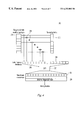
- FIG. 2 c presents a receiver training sequence in accordance with the present invention
- FIG. 3 presents a flow diagram for DMT boundary estimation in accordance with the present invention
- FIG. 4 shows a hardware diagram of an apparatus in accordance with the present invention.
- FIGS. 5 a - 5 c illustrate the windowing effect of using a subset of equalizer frequencies.
- the transceiver's receiver Upon establishing a communications link over a channel, the transceiver's receiver begins to train its frequency domain equalizer to compensate for amplitude and phase distortion in the communications channel comprising a twisted pair.
- the equalizer uses a reference pattern containing the training sequence to force the taps to alter the received signal so that it matches the reference pattern.
- FIG. 2 c illustrates the training sequence used in conjunction with the present invention.
- the first TDF tap is set to 1 and the rest of the TDF vector is set to 0. Therefore, the TDF initially serves as an all-pass filter.
- a first round of training is performed to determine the coefficients of an initial FEQ. This first round of training uses one of several established techniques, such as those disclosed in the above-identified references. At the conclusion of the first round of training, the FEQ is initially trained, but no ISI mitigation has been performed since the TDF is a single impulse and the symbol boundary has not been identified.
- a first round of DMT symbol boundary detection is performed to determine a initial boundary offset n i based on the initial FEQ.
- step 306 the initial FEQ is used to calculate the TDF to help mitigate ISI.
- Initial boundary offset n i can be used here to help center the peak of TDF, which now is no longer a single impulse.
- step 308 a second round of training is conducted to determine a refined FEQ, again using standard techniques known in the art. For this second round of training, however, the calculated TDF, which is no longer a single impulse, is used to help mitigate ISI.
- step 310 a second round of DMT symbol boundary detection is conducted to find a refined boundary offset n r , which may thereafter be used in DMT symbol boundary determinations.
- step 312 the input sample buffer is adjusted by n r to align the FFT input vector boundary to a symbol boundary.
- step 314 the FEQ taps are rotated (i.e., phase shifted) to compensate for the adjusted sample buffer.
- the resulting process compensates for any sample phase offset caused by the receiver's lack of synchronization with the transmitter symbol phase, as well as physical time delays such as system delay and transmission wire delay.
- the TDF counteracts ISI
- the FEQ counteracts attenuation and phase distortion due to the channel.
- the taps of the FEQ may be calculated in a number of ways, such as aforementioned U.S. Pat. Nos. 5,461,640 and 5,870,432, and so will not be discussed here in further detail.
- a cyclical sequence of DMT symbols is used to train the xDSL Modem.
- the full length FEQ also has 128 complex taps.
- N may be some other number and this will consequently affect the number of tap coefficients for a full-length equalizer.
- FIG. 3 shows a flow diagram in accordance with the present invention for calculating an offset n 0 to determine the DMT symbol boundary in either step 304 or step 310 of FIG. 2 c.
- N 1 N/2
- step 130 the amplitude of each of the N/2 complex taps is ignored. This can be done in a number of ways. One way is to scale each complex tap of W[k] to the same amplitude, say 1.0, by creating a normalized vector Z[k] comprising the equalizer's phase information:
- Z[k] itself can be formed directly as above, or in a two-step process which first calculates a vector of scale factors:
- Z[k] focuses only on the phase information in the equalizer because it is the phase information that is of interest for boundary detection. This is because it is the phase offset (rather than any amplitude attenuation) between the transmitter and the receiver that alters the phases of the N/2 complex taps.
- the channel has substantially linear phase and so the group delay of the samples is representative of the boundary between DMT symbols.
- the first N/2 values of H[k] are the same as the first N/2 values of Z[k].
- H[N/2] is zero and the remaining N/2 ⁇ 1 values are the complex conjugates of the last N/2 ⁇ 1 values of Z[k] in reverse order so as to ensure that H[k] has Hermitian symmetry.
- step 150 the inverse discrete fourier transform, preferably implemented via an IFFT, of H[k] is taken resulting in a real time domain vector h[n] of length N.
- h[n] is real because of the conjugate symmetry of H[k].
- step 160 the index of the peak value of the real coefficients within h[n] is identified. This index corresponds to the group delay of the samples in the equalizer and thus represents the boundary of the DMT symbols as a function of sample position.
- the steps shown in FIG. 3 can be carried out entirely by programming the signal processor resident in an xDSL modem, or a processor associated with an xDSL modem. Therefore, the various vectors discussed above are principally just labels for data objects manipulated in software. These data objects may occupy distinct locations in physical memory. Alternatively, one or more of the vectors may share the same physical memory locations—for instance, the original contents of equalizer W[k] may be replaced point by point by their normalized values, and/or normalized vector Z[k] may simply comprise the first N/2 elements of H[k], and other such variations may be possible.
- FIG. 4 shows an idealized hardware implementation 200 in accordance with one embodiment of the present invention.
- the N/2 frequency-domain weights W[k] are calculated using conventional techniques as discussed above and are stored in first memory 210 .
- the scaling vector S[k] is calculated from the frequency-domain weights by means of a signal processor, a divider perhaps implemented as shift-and-subtract hardware, or the like, to divide the magnitudes of the W[k] or the like, and store the resulting S[k] in a second memory 212 .
- the N/2 values in the third memory 216 which represent Z[k] discussed above, can also serve as the first N/2 values of H[k], although this is not an absolute necessity.
- the N-length H[k] vector is then transformed by an inverse discrete fourier transformer 220 , implemented with a DSP chip, or the like.
- the result of the transformer 220 , h[n], is stored in a fifth memory 222 .
- Fifth memory 222 may be the same as the combined third and fourth memories, in which case h[n] replaces H[k] and H[k] is lost.
- the fifth memory may be distinct from the combined third and fourth memories 216 , 218 , respectively, in which case H[k] and h[n] may coexist.
- a maximum magnitude finder 224 is then used to identify the index n 0 of the tap of h[n] having the largest value. This index n 0 is representative of the boundary of the DMT symbol.
- the multipliers 214 , the inverse discrete fourier transformer 220 and the maximum magnitude finder 224 are implemented in software which executes on a signal processor associated with the xDSL modem.
- these items can be implemented by a computing engine associated with the xDSL modem.
- the computing engine may be implemented by a co-processor, a vector processor, a DSP chip, or the like connected to the signal processor.
- some, or all of these steps may be implemented in special purpose hardware, and the hardware itself may take on different forms such as being implemented on a PC board, perhaps as a host-based or “soft” modem, or as a custom or semi-custom integrated circuit, such as an ASIC or gate array.
- a programmable DSP chip or a soft modem which allows a user to modify the executable software code resident therein, one may perhaps download appropriate software from the internet.
- the downloaded software may be loaded into a flash RAM, or the like, associated with the xDSL modem.
- the various memories described above may be a part of a common RAM connected to the computing engine and partitioned by software into a plurality of vectors accessed by software, firmware or directly by hardware. Alternatively, some or all of the various memories may be distinct from one another, comprising special purpose registers or buffers. These memories may be provided as a separate chip, a sub-circuit on a processor chip, or in any one of a number of different ways known to those skilled in the art. It should also be kept in mind that the hardware of FIG. 4 would also necessarily include control circuitry, oscillator signals, power supply lines and other well-known incidental features which are not shown.
- each real and imaginary part of an element of either W[k] or Z[k] comprises a mantissa and an exponent.
- the exponents of both the real and imaginary parts of Z[k], and even of W[k] have a limited dynamic range. This allows one to adjust the finite bit-length mantissas by shifting the mantissa's bits to ensure that the exponents for both the real and imaginary parts for all elements of a vector are the same.
- N/2 bins of the frequency response of the channel equalizer are used. This, however, is not an absolute requirement.
- the subset may comprise contiguous bins, or may instead comprise sampled bins—such as every other bin over a predetermined range.
- any group delay in the time domain h[n] will be convolved with a ‘sinc’ function, thereby spreading the peak of the group delay over a number of time domain bins, depending on the width of the window, i.e., the number of frequency bins of the equalizer that are used.
- FIGS. 5 a-c illustrate the effect of using only a finite number of frequency bins of the equalizer W[k] to calculate the DMT boundary based on the group delay, assuming that the equalizer has a total of N/2 frequency bins. In FIG. 5 a , only the bins between frequency indices k 1 and k 2 are used.
- H[k] is then an N-length vector in which only bins k 1 to k 2 and (N ⁇ k 2 ) to (N ⁇ k 1 ) are used.
- h[n] exhibits a peak at some delay index n d .
- This delay index corresponds to the group delay in the equalizer, and so is reflective of the DMT symbol boundary.
- N/2, k 1 and k 2 may be selected to conform to one or more international communications standards.
- N/2 is 128, k 1 is no greater than in 37 and k 2 is no less than bin 68 .
- N/2 is 32, k 1 is no greater than 6 and k 2 is no greater than 31. It should be kept in mind, however, that N, k 1 and k 2 may assume a wide range of values.
Abstract
Description
Claims (27)
Priority Applications (6)
| Application Number | Priority Date | Filing Date | Title |
|---|---|---|---|
| US09/394,619 US6252902B1 (en) | 1999-09-13 | 1999-09-13 | xDSL modem having DMT symbol boundary detection |
| PCT/US2000/024849 WO2001020794A1 (en) | 1999-09-13 | 2000-09-11 | xDSL MODEM HAVING DMT SYMBOL BOUNDARY DETECTION |
| DE10083116T DE10083116T1 (en) | 1999-09-13 | 2000-09-11 | xDSL modem with DMT symbol limit detection |
| GB0111432A GB2360181B (en) | 1999-09-13 | 2000-09-11 | xDSL modem having DMT symbol boundary detection |
| AU74776/00A AU7477600A (en) | 1999-09-13 | 2000-09-11 | Xdsl modem having dmt symbol boundary detection |
| TW089118720A TW480834B (en) | 1999-09-13 | 2000-09-26 | xDSL modem having DMT symbol boundary detection |
Applications Claiming Priority (1)
| Application Number | Priority Date | Filing Date | Title |
|---|---|---|---|
| US09/394,619 US6252902B1 (en) | 1999-09-13 | 1999-09-13 | xDSL modem having DMT symbol boundary detection |
Publications (1)
| Publication Number | Publication Date |
|---|---|
| US6252902B1 true US6252902B1 (en) | 2001-06-26 |
Family
ID=23559732
Family Applications (1)
| Application Number | Title | Priority Date | Filing Date |
|---|---|---|---|
| US09/394,619 Expired - Lifetime US6252902B1 (en) | 1999-09-13 | 1999-09-13 | xDSL modem having DMT symbol boundary detection |
Country Status (6)
| Country | Link |
|---|---|
| US (1) | US6252902B1 (en) |
| AU (1) | AU7477600A (en) |
| DE (1) | DE10083116T1 (en) |
| GB (1) | GB2360181B (en) |
| TW (1) | TW480834B (en) |
| WO (1) | WO2001020794A1 (en) |
Cited By (11)
| Publication number | Priority date | Publication date | Assignee | Title |
|---|---|---|---|---|
| US20010037471A1 (en) * | 2000-03-01 | 2001-11-01 | Ming-Kang Liu | System and method for internal operation of multiple-port xDSL communications systems |
| US20020023086A1 (en) * | 2000-06-30 | 2002-02-21 | Ponzio, Jr. Frank J. | System and method for providing signaling quality and integrity of data content |
| US20020037058A1 (en) * | 2000-07-07 | 2002-03-28 | Koninklijke Philips Electronics N.V. | Frequency-domain equalizer for terrestrial digital TV reception |
| WO2003055117A2 (en) * | 2001-12-11 | 2003-07-03 | Siemens Aktiengesellschaft | Method for the continuous estimation of the equalizer coefficients for wire-bound transmission systems |
| US20040001535A1 (en) * | 2002-06-28 | 2004-01-01 | Anand Kannan | Modem having a vector-architecture processor, and associated methodology therefor |
| US20040017849A1 (en) * | 2002-07-29 | 2004-01-29 | Panosonic Communications Co., Ltd. | ADSL modem apparatus and communication method for the ADSL modem apparatus |
| WO2005060196A1 (en) * | 2003-12-17 | 2005-06-30 | Nec Corporation | Demodulation of a multi-level quadrature amplitude modulation signal |
| US20050270987A1 (en) * | 2001-01-16 | 2005-12-08 | Yuanjie Chen | Selectable training signals based on stored previous connection information for DMT-based system |
| US6990083B1 (en) * | 2000-10-27 | 2006-01-24 | Tioga Technologies, Ltd. | Method and device for computing echo-cancellation coefficients using FFT |
| US7020212B1 (en) * | 2000-07-31 | 2006-03-28 | 3Com Corporation | Method and system for a multiple dimensional adaptive frequency domain noise canceler for DMT transceivers |
| US20080080606A1 (en) * | 2006-09-29 | 2008-04-03 | Peiqing Wang | Method and System for Performing Timing Recovery in a Digital Communication System |
Citations (15)
| Publication number | Priority date | Publication date | Assignee | Title |
|---|---|---|---|---|
| US5285474A (en) | 1992-06-12 | 1994-02-08 | The Board Of Trustees Of The Leland Stanford, Junior University | Method for equalizing a multicarrier signal in a multicarrier communication system |
| US5461640A (en) | 1994-06-03 | 1995-10-24 | Texas Instruments Incorporated | Method and system for optimizing an equalizer in a data transmission system |
| US5479447A (en) | 1993-05-03 | 1995-12-26 | The Board Of Trustees Of The Leland Stanford, Junior University | Method and apparatus for adaptive, variable bandwidth, high-speed data transmission of a multicarrier signal over digital subscriber lines |
| US5625651A (en) | 1994-06-02 | 1997-04-29 | Amati Communications, Inc. | Discrete multi-tone data transmission system using an overhead bus for synchronizing multiple remote units |
| US5748686A (en) | 1996-04-04 | 1998-05-05 | Globespan Technologies, Inc. | System and method producing improved frame synchronization in a digital communication system |
| US5870432A (en) | 1995-10-11 | 1999-02-09 | Alcatel N. V. | Method for transmission line impulse response equalization and a device to perform this method |
| US5901180A (en) * | 1994-07-15 | 1999-05-04 | Amati Communications Corp. | Frame synchronization in multicarrier transmission systems |
| US5987005A (en) * | 1997-07-02 | 1999-11-16 | Telefonaktiebolaget Lm Ericsson | Method and apparatus for efficient computation of discrete fourier transform (DFT) and inverse discrete fourier transform |
| US6031882A (en) * | 1994-07-19 | 2000-02-29 | Trimble Navigation Limited | Adaptive equalization of multipath signals |
| US6031868A (en) * | 1997-10-17 | 2000-02-29 | Analog Devices, Inc. | Asymmetric digital subscriber loop transceivers |
| US6035000A (en) * | 1996-04-19 | 2000-03-07 | Amati Communications Corporation | Mitigating radio frequency interference in multi-carrier transmission systems |
| US6047025A (en) * | 1998-02-13 | 2000-04-04 | Motorola, Inc. | Method and apparatus for equallization in an asymmetric digital aubscriber line communications system |
| US6130918A (en) * | 1997-12-01 | 2000-10-10 | Nortel Networks Limited | Method and apparatus for reducing the peak-to-average ratio in a multicarrier communication system |
| US6137848A (en) * | 1997-11-03 | 2000-10-24 | At&T Corp. | Method and system for joint timing recovery and channel estimation for DMT modems |
| US6137839A (en) * | 1996-05-09 | 2000-10-24 | Texas Instruments Incorporated | Variable scaling of 16-bit fixed point fast fourier forward and inverse transforms to improve precision for implementation of discrete multitone for asymmetric digital subscriber loops |
-
1999
- 1999-09-13 US US09/394,619 patent/US6252902B1/en not_active Expired - Lifetime
-
2000
- 2000-09-11 DE DE10083116T patent/DE10083116T1/en not_active Withdrawn
- 2000-09-11 AU AU74776/00A patent/AU7477600A/en not_active Abandoned
- 2000-09-11 GB GB0111432A patent/GB2360181B/en not_active Expired - Fee Related
- 2000-09-11 WO PCT/US2000/024849 patent/WO2001020794A1/en active Application Filing
- 2000-09-26 TW TW089118720A patent/TW480834B/en not_active IP Right Cessation
Patent Citations (16)
| Publication number | Priority date | Publication date | Assignee | Title |
|---|---|---|---|---|
| US5285474A (en) | 1992-06-12 | 1994-02-08 | The Board Of Trustees Of The Leland Stanford, Junior University | Method for equalizing a multicarrier signal in a multicarrier communication system |
| US5479447A (en) | 1993-05-03 | 1995-12-26 | The Board Of Trustees Of The Leland Stanford, Junior University | Method and apparatus for adaptive, variable bandwidth, high-speed data transmission of a multicarrier signal over digital subscriber lines |
| US5625651A (en) | 1994-06-02 | 1997-04-29 | Amati Communications, Inc. | Discrete multi-tone data transmission system using an overhead bus for synchronizing multiple remote units |
| US5933454A (en) * | 1994-06-02 | 1999-08-03 | Amati Communications Corporation | Multi-carrier data transmissions system using an overhead bus for synchronizing multiple remote units |
| US5461640A (en) | 1994-06-03 | 1995-10-24 | Texas Instruments Incorporated | Method and system for optimizing an equalizer in a data transmission system |
| US5901180A (en) * | 1994-07-15 | 1999-05-04 | Amati Communications Corp. | Frame synchronization in multicarrier transmission systems |
| US6031882A (en) * | 1994-07-19 | 2000-02-29 | Trimble Navigation Limited | Adaptive equalization of multipath signals |
| US5870432A (en) | 1995-10-11 | 1999-02-09 | Alcatel N. V. | Method for transmission line impulse response equalization and a device to perform this method |
| US5748686A (en) | 1996-04-04 | 1998-05-05 | Globespan Technologies, Inc. | System and method producing improved frame synchronization in a digital communication system |
| US6035000A (en) * | 1996-04-19 | 2000-03-07 | Amati Communications Corporation | Mitigating radio frequency interference in multi-carrier transmission systems |
| US6137839A (en) * | 1996-05-09 | 2000-10-24 | Texas Instruments Incorporated | Variable scaling of 16-bit fixed point fast fourier forward and inverse transforms to improve precision for implementation of discrete multitone for asymmetric digital subscriber loops |
| US5987005A (en) * | 1997-07-02 | 1999-11-16 | Telefonaktiebolaget Lm Ericsson | Method and apparatus for efficient computation of discrete fourier transform (DFT) and inverse discrete fourier transform |
| US6031868A (en) * | 1997-10-17 | 2000-02-29 | Analog Devices, Inc. | Asymmetric digital subscriber loop transceivers |
| US6137848A (en) * | 1997-11-03 | 2000-10-24 | At&T Corp. | Method and system for joint timing recovery and channel estimation for DMT modems |
| US6130918A (en) * | 1997-12-01 | 2000-10-10 | Nortel Networks Limited | Method and apparatus for reducing the peak-to-average ratio in a multicarrier communication system |
| US6047025A (en) * | 1998-02-13 | 2000-04-04 | Motorola, Inc. | Method and apparatus for equallization in an asymmetric digital aubscriber line communications system |
Non-Patent Citations (1)
| Title |
|---|
| Thierry Pollet and Miguel Peeters, Alcatel "Synchronization with DMT Modulation" p. 80-86; IEEE Commications Magazine (Apr./1999). |
Cited By (35)
| Publication number | Priority date | Publication date | Assignee | Title |
|---|---|---|---|---|
| US7085285B2 (en) | 2000-03-01 | 2006-08-01 | Realtek Semiconductor Corp. | xDSL communications systems using shared/multi-function task blocks |
| US20060203843A1 (en) * | 2000-03-01 | 2006-09-14 | Realtek Semiconductor Corp. | xDSL function ASIC processor & method of operation |
| US20010049757A1 (en) * | 2000-03-01 | 2001-12-06 | Ming-Kang Liu | Programmable task scheduler for use with multiport xDSL processing system |
| US6965960B2 (en) * | 2000-03-01 | 2005-11-15 | Realtek Semiconductor Corporation | xDSL symbol processor and method of operating same |
| US20020010810A1 (en) * | 2000-03-01 | 2002-01-24 | Ming-Kang Liu | xDSL function ASIC processor & method of operation |
| US8325751B2 (en) | 2000-03-01 | 2012-12-04 | Realtek Semiconductor Corp. | Mixed hardware/software architecture and method for processing communications |
| US7818748B2 (en) | 2000-03-01 | 2010-10-19 | Realtek Semiconductor Corporation | Programmable task scheduler |
| US7295571B2 (en) | 2000-03-01 | 2007-11-13 | Realtek Semiconductor Corp. | xDSL function ASIC processor and method of operation |
| US20020049581A1 (en) * | 2000-03-01 | 2002-04-25 | Ming-Kang Liu | Physical medium dependent sub-system with shared resources for multiport xDSL system |
| US7200138B2 (en) | 2000-03-01 | 2007-04-03 | Realtek Semiconductor Corporation | Physical medium dependent sub-system with shared resources for multiport xDSL system |
| US20010047434A1 (en) * | 2000-03-01 | 2001-11-29 | Ming-Kang Liu | xDSL communications systems using shared/multi-function task blocks |
| US20010037471A1 (en) * | 2000-03-01 | 2001-11-01 | Ming-Kang Liu | System and method for internal operation of multiple-port xDSL communications systems |
| US7075941B2 (en) | 2000-03-01 | 2006-07-11 | Real Communications, Inc. | Scaleable architecture for multiple-port, system-on-chip ADSL communications systems |
| US20050071800A1 (en) * | 2000-03-01 | 2005-03-31 | Realtek Semiconductor Corporation | Mixed hardware/sofware architecture and method for processing xDSL communications |
| US7032223B2 (en) | 2000-03-01 | 2006-04-18 | Realtek Semiconductor Corp. | Transport convergence sub-system with shared resources for multiport xDSL system |
| US6986073B2 (en) | 2000-03-01 | 2006-01-10 | Realtek Semiconductor Corp. | System and method for a family of digital subscriber line (XDSL) signal processing circuit operating with an internal clock rate that is higher than all communications ports operating with a plurality of port sampling clock rates |
| US20020008256A1 (en) * | 2000-03-01 | 2002-01-24 | Ming-Kang Liu | Scaleable architecture for multiple-port, system-on-chip ADSL communications systems |
| US20020010849A1 (en) * | 2000-03-01 | 2002-01-24 | Ming-Kang Liu | Data object architecture and method for xDSL ASIC processor |
| US20020023086A1 (en) * | 2000-06-30 | 2002-02-21 | Ponzio, Jr. Frank J. | System and method for providing signaling quality and integrity of data content |
| US6912258B2 (en) * | 2000-07-07 | 2005-06-28 | Koninklijke Philips Electtronics N.V. | Frequency-domain equalizer for terrestrial digital TV reception |
| US20020037058A1 (en) * | 2000-07-07 | 2002-03-28 | Koninklijke Philips Electronics N.V. | Frequency-domain equalizer for terrestrial digital TV reception |
| US7020212B1 (en) * | 2000-07-31 | 2006-03-28 | 3Com Corporation | Method and system for a multiple dimensional adaptive frequency domain noise canceler for DMT transceivers |
| US6990083B1 (en) * | 2000-10-27 | 2006-01-24 | Tioga Technologies, Ltd. | Method and device for computing echo-cancellation coefficients using FFT |
| US20050270987A1 (en) * | 2001-01-16 | 2005-12-08 | Yuanjie Chen | Selectable training signals based on stored previous connection information for DMT-based system |
| WO2003055117A2 (en) * | 2001-12-11 | 2003-07-03 | Siemens Aktiengesellschaft | Method for the continuous estimation of the equalizer coefficients for wire-bound transmission systems |
| US20050063499A1 (en) * | 2001-12-11 | 2005-03-24 | Thomas Ahrndt | Method for the continuous estimation of the equalizer coefficients for wire-bound transmission systems |
| WO2003055117A3 (en) * | 2001-12-11 | 2005-09-01 | Siemens Ag | Method for the continuous estimation of the equalizer coefficients for wire-bound transmission systems |
| US7154941B2 (en) * | 2002-06-28 | 2006-12-26 | Nokia Corporation | Modem having a vector-architecture processor, and associated methodology therefor |
| US20040001535A1 (en) * | 2002-06-28 | 2004-01-01 | Anand Kannan | Modem having a vector-architecture processor, and associated methodology therefor |
| US20040017849A1 (en) * | 2002-07-29 | 2004-01-29 | Panosonic Communications Co., Ltd. | ADSL modem apparatus and communication method for the ADSL modem apparatus |
| WO2005060196A1 (en) * | 2003-12-17 | 2005-06-30 | Nec Corporation | Demodulation of a multi-level quadrature amplitude modulation signal |
| CN1894919B (en) * | 2003-12-17 | 2010-08-18 | 日本电气株式会社 | Demodulation of a multi-level quadrature amplitude modulation signal |
| US20070185949A1 (en) * | 2003-12-17 | 2007-08-09 | Nec Corporation | Demodulation of a multi-level quadrature amplitude modulation signal |
| US20080080606A1 (en) * | 2006-09-29 | 2008-04-03 | Peiqing Wang | Method and System for Performing Timing Recovery in a Digital Communication System |
| US7933323B2 (en) * | 2006-09-29 | 2011-04-26 | Broadcom Corporation | Method and system for performing timing recovery in a digital communication system |
Also Published As
| Publication number | Publication date |
|---|---|
| WO2001020794A1 (en) | 2001-03-22 |
| GB0111432D0 (en) | 2001-07-04 |
| DE10083116T1 (en) | 2001-10-04 |
| TW480834B (en) | 2002-03-21 |
| AU7477600A (en) | 2001-04-17 |
| GB2360181A8 (en) | 2004-06-14 |
| GB2360181B (en) | 2004-04-14 |
| GB2360181A (en) | 2001-09-12 |
Similar Documents
| Publication | Publication Date | Title |
|---|---|---|
| US6233276B1 (en) | XDSL modem having time domain filter for ISI mitigation | |
| US7561627B2 (en) | Method and system for channel equalization and crosstalk estimation in a multicarrier data transmission system | |
| US6097763A (en) | MMSE equalizers for DMT systems with cross talk | |
| US7623578B2 (en) | Time domain equalization using frequency domain operations | |
| AU750466B2 (en) | A multicarrier receiver | |
| US6266367B1 (en) | Combined echo canceller and time domain equalizer | |
| US7656976B2 (en) | Systems and methods for multicarrier modulation using multi-tap frequency-domain equalizer and decision feedback | |
| EP0912023A1 (en) | Demodulation and equalisation of multicarrier signals | |
| JP2000307481A (en) | Receiver for discrete multitone modulated signal having window function | |
| EP1314260B1 (en) | Frequency domain echo canceller | |
| US6252902B1 (en) | xDSL modem having DMT symbol boundary detection | |
| JP2000165347A (en) | High-speed start-up for communication system of discrete multitone base | |
| US6603811B1 (en) | Low complexity frequency domain equalizer having fast re-lock | |
| US6687288B1 (en) | NEXT cancellation for modem pools | |
| US7463678B2 (en) | Equalization scheme for DSL receivers in presence of an under-sampled or over-sampled transmit IDFT | |
| EP0969637A1 (en) | Equalisation in multicarrier receivers | |
| EP1296492B1 (en) | Multicarrier receiver with a sliding window Fourier transform and a Fourier transform | |
| EP1303093B1 (en) | Impuse response shortening in DMT modems | |
| Djokovic | MMSE equalizers for DMT systems with and without crosstalk | |
| JP2002526981A (en) | Digital receiver for signals generated by discrete multitone modulation | |
| Ho | Multicarrier echo cancellation and multichannel equalization | |
| Djokovic | Cyclic prefix extension in DMT systems | |
| EP1434363A1 (en) | Efficient echo canceller and method |
Legal Events
| Date | Code | Title | Description |
|---|---|---|---|
| AS | Assignment |
Owner name: VIRATA CORPORATION, UNITED KINGDOM Free format text: ASSIGNMENT OF ASSIGNORS INTEREST;ASSIGNORS:SIMEON, RICHARD;BEANEY, JAMES;REEL/FRAME:010243/0679;SIGNING DATES FROM 19990901 TO 19990902 |
|
| AS | Assignment |
Owner name: VENTRUE BANKING GROUP, A DIVISION OF CUPERTINO NAT Free format text: COLLATERAL ASSIGNMENT, PATENT MORTGAGE AND SECURITY AGREEMENT;ASSIGNOR:VIRATA CORPORATION;REEL/FRAME:011019/0669 Effective date: 20000606 |
|
| AS | Assignment |
Owner name: VIRATA CORPORATION, CALIFORNIA Free format text: RELEASE OF PATENT SECURITY;ASSIGNOR:VENTURE BANKING GROUP, A DIVISION OF CUPERTINO NATIONAL BANK;REEL/FRAME:011238/0063 Effective date: 20001030 |
|
| STCF | Information on status: patent grant |
Free format text: PATENTED CASE |
|
| REMI | Maintenance fee reminder mailed | ||
| FPAY | Fee payment |
Year of fee payment: 4 |
|
| SULP | Surcharge for late payment | ||
| AS | Assignment |
Owner name: CONEXANT, INC.,NEW JERSEY Free format text: CHANGE OF NAME;ASSIGNOR:GLOBESPANVIRATA, INC.;REEL/FRAME:018471/0286 Effective date: 20040528 Owner name: CONEXANT, INC., NEW JERSEY Free format text: CHANGE OF NAME;ASSIGNOR:GLOBESPANVIRATA, INC.;REEL/FRAME:018471/0286 Effective date: 20040528 Owner name: GLOBESPANVIRATA, INC., NEW JERSEY Free format text: MERGER;ASSIGNOR:VIRATA CORPORATION;REEL/FRAME:018471/0070 Effective date: 20040428 |
|
| AS | Assignment |
Owner name: BANK OF NEW YORK TRUST COMPANY, N.A.,ILLINOIS Free format text: SECURITY INTEREST;ASSIGNOR:CONEXANT, INC.;REEL/FRAME:018545/0298 Effective date: 20061113 Owner name: BANK OF NEW YORK TRUST COMPANY, N.A., ILLINOIS Free format text: SECURITY INTEREST;ASSIGNOR:CONEXANT, INC.;REEL/FRAME:018545/0298 Effective date: 20061113 |
|
| FPAY | Fee payment |
Year of fee payment: 8 |
|
| AS | Assignment |
Owner name: CONEXANT, INC., CALIFORNIA Free format text: RELEASE BY SECURED PARTY;ASSIGNOR:THE BANK OF NEW YORK MELLON TRUST COMPANY, N.A.;REEL/FRAME:023134/0221 Effective date: 20090821 |
|
| AS | Assignment |
Owner name: IKANOS COMMUNICATIONS, INC., CALIFORNIA Free format text: ASSIGNMENT OF ASSIGNORS INTEREST;ASSIGNORS:CONEXANT SYSTEMS, INC.;CONEXANT, INC.;BROOKTREE BROADBAND HOLDING INC.;REEL/FRAME:023163/0723 Effective date: 20090824 Owner name: IKANOS COMMUNICATIONS, INC.,CALIFORNIA Free format text: ASSIGNMENT OF ASSIGNORS INTEREST;ASSIGNORS:CONEXANT SYSTEMS, INC.;CONEXANT, INC.;BROOKTREE BROADBAND HOLDING INC.;REEL/FRAME:023163/0723 Effective date: 20090824 |
|
| FPAY | Fee payment |
Year of fee payment: 12 |
|
| AS | Assignment |
Owner name: ALCATEL-LUCENT USA, INC., NEW JERSEY Free format text: NOTICE OF GRANT OF SECURITY INTEREST IN PATENTS;ASSIGNOR:IKANOS COMMUNICATIONS, INC.;REEL/FRAME:035581/0710 Effective date: 20150430 |
|
| AS | Assignment |
Owner name: SILICON VALLEY BANK, CALIFORNIA Free format text: SECURITY INTEREST;ASSIGNOR:IKANOS COMMUNICATIONS, INC.;REEL/FRAME:035874/0351 Effective date: 20150602 |
|
| AS | Assignment |
Owner name: IKANOS COMMUNICATIONS, INC., CALIFORNIA Free format text: RELEASE BY SECURED PARTY;ASSIGNOR:SILICON VALLEY BANK;REEL/FRAME:036733/0031 Effective date: 20150930 Owner name: IKANOS COMMUNICATIONS, INC., CALIFORNIA Free format text: RELEASE BY SECURED PARTY;ASSIGNOR:ALCATEL-LUCENT USA, INC.;REEL/FRAME:036732/0876 Effective date: 20150929 |
|
| FEPP | Fee payment procedure |
Free format text: PAYOR NUMBER ASSIGNED (ORIGINAL EVENT CODE: ASPN); ENTITY STATUS OF PATENT OWNER: SMALL ENTITY |