US6264494B1 - Electric cable and connector arrangement - Google Patents
Electric cable and connector arrangement Download PDFInfo
- Publication number
- US6264494B1 US6264494B1 US09/710,858 US71085800A US6264494B1 US 6264494 B1 US6264494 B1 US 6264494B1 US 71085800 A US71085800 A US 71085800A US 6264494 B1 US6264494 B1 US 6264494B1
- Authority
- US
- United States
- Prior art keywords
- electric wires
- electric
- data transmission
- connector
- transmission cable
- Prior art date
- Legal status (The legal status is an assumption and is not a legal conclusion. Google has not performed a legal analysis and makes no representation as to the accuracy of the status listed.)
- Expired - Fee Related
Links
Images


Classifications
-
- H—ELECTRICITY
- H01—ELECTRIC ELEMENTS
- H01R—ELECTRICALLY-CONDUCTIVE CONNECTIONS; STRUCTURAL ASSOCIATIONS OF A PLURALITY OF MUTUALLY-INSULATED ELECTRICAL CONNECTING ELEMENTS; COUPLING DEVICES; CURRENT COLLECTORS
- H01R4/00—Electrically-conductive connections between two or more conductive members in direct contact, i.e. touching one another; Means for effecting or maintaining such contact; Electrically-conductive connections having two or more spaced connecting locations for conductors and using contact members penetrating insulation
- H01R4/24—Connections using contact members penetrating or cutting insulation or cable strands
- H01R4/2416—Connections using contact members penetrating or cutting insulation or cable strands the contact members having insulation-cutting edges, e.g. of tuning fork type
- H01R4/242—Connections using contact members penetrating or cutting insulation or cable strands the contact members having insulation-cutting edges, e.g. of tuning fork type the contact members being plates having a single slot
- H01R4/2425—Flat plates, e.g. multi-layered flat plates
- H01R4/2429—Flat plates, e.g. multi-layered flat plates mounted in an insulating base
- H01R4/2433—Flat plates, e.g. multi-layered flat plates mounted in an insulating base one part of the base being movable to push the cable into the slot
-
- H—ELECTRICITY
- H01—ELECTRIC ELEMENTS
- H01R—ELECTRICALLY-CONDUCTIVE CONNECTIONS; STRUCTURAL ASSOCIATIONS OF A PLURALITY OF MUTUALLY-INSULATED ELECTRICAL CONNECTING ELEMENTS; COUPLING DEVICES; CURRENT COLLECTORS
- H01R13/00—Details of coupling devices of the kinds covered by groups H01R12/70 or H01R24/00 - H01R33/00
- H01R13/62—Means for facilitating engagement or disengagement of coupling parts or for holding them in engagement
- H01R13/621—Bolt, set screw or screw clamp
- H01R13/6215—Bolt, set screw or screw clamp using one or more bolts
Landscapes
- Coupling Device And Connection With Printed Circuit (AREA)
Abstract
An electric cable and connector arrangement in which a harness is fastened to the electric wires of the data transmission cable to hold the electric wires in a row, for enabling the electric wires to be accurately and quickly arranged in respective wire grooves of a wire distribution plate of the electric connector, and the connector head of the electric connector has two bottom mounting legs respectively plugged into respective plug holes in the housing of the electric connector.
Description
The present invention relates to an electric cable and connector arrangement and, more particularly, to such an electric cable and connector arrangement, in which harness means is installed in the data transmission cable to hold the electric wires in a row so that the electric wires can accurately and quickly be installed in respective wire grooves on of the wire distribution plate of the electric connector.
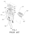
FIG. 1 shows an electric cable and connector arrangement for data transmission according to the prior art. According to this arrangement, the electric connector, referenced by 10′, comprises a housing 20′ defining a receiving chamber 22′, a wire distribution plate 40′, a holding-down plate 44′, and a connector head 50′. The cable, referenced by 30′, is inserted from the rear side of the housing 20′ into the receiving chamber 22′, comprising a set of electric wires 32′, and an aluminum foil layer 38′ embedded within the outer insulative layer thereof and wrapped on the electric wires 32′. The wire distribution plate 40′ and the holding-down plate 44′ each have a plurality of wire grooves 48′ respectively arranged at the top or bottom side. The electric wires 32′ of the cable 30′ are respectively mounted in the wire grooves 48′ of the wire distribution plate 40′ and the holding-down plate 44′. The holding-down plate 44′ is fastened to the wire distribution plate 40′ to hold down the electric wires 32′ of the cable 30′ in the wire grooves 48′. The wire-distribution plate 40′ comprises a plurality of pin holes 42′. The holding-down plate 44′ comprises a plurality of bottom pins 46′ respectively press-fitted into the pinholes 42′ of the wire distribution plate 40′. The connector head 50′ comprises a set of contact pins 51′ for power and data signal transmission. The contact pins 51′ each have a sharp, notched bottom mounting end adapted for connecting to the conductor of each electric wire 32′ of the cable 30′. After the holding-down plate 44′ and the wire distribution plate 40′ had been fastened together to hold down the electric wires 32′ of the cable 30′, the connector head 50′ is fastened to the housing 20′ and covered on the receiving chamber 22′ to force the contact pins 52′ against the electric wires 32′, and therefore the sharp, notched bottom end of each contact pin 52′ pierces the insulator of each electric wire 32′ of the cable 30′ to achieve a respective electric contact. This cable and connector arrangement still has drawbacks as outlined hereinafter:
1. Because the electric wires 32′ go off in different directions after the outer insulator and aluminum foil layer 39 of the cable 30′ had been cut off at a distance, it takes much time to arrange the electric wires 32′ in the wire grooves 48′ of the wire distribution plate 40′ and the holding-down plate 44′, and the electric wires 32′ may be erroneously arranged in wrong positions.
2. The complicated procedure of the arrangement of the electric wires 32′ affects the speed of the processing work and the quality of the finished product.
3. After connection of the connector head 50′ to the housing 20′, an additional encapsulation or fixation procedure is required to fixedly secure the housing 20′ and the connector head 50′ together.
The present invention has been accomplished to provide an electric cable and connector arrangement, which eliminates the aforesaid drawbacks. It is one object of the present invention to provide an electric cable and connector arrangement, which keeps the electric wires of the cable in a row for quick installation. It is another object of the present invention to provide an electric cable and connector arrangement, which keeps the electric wires of the cable in a line so that the electric wires can be accurately positioned without causing a contact error. According to one aspect of the present invention, a harness is fastened to the electric wires of the data transmission cable to hold the electric wires in a row, for enabling the electric wires to be quickly arranged in respective wire grooves of a wire distribution plate of the electric connector. Because the electric wires of the data transmission cable is held in a row by the harness, the electric wires can be accurately arranged in the respective wire grooves in the wire distribution plate and the holding-down plate of the electric connector. According to another aspect of the present invention, the housing of the electric connector comprises two plugholes longitudinally arranged in parallel, and the connector head of the electric connector has two bottom mounting legs respectively plugged into the plugholes of the housing by force. After press-fitting the mounting legs of the connector head into the plugholes of the housing, the electric connector is well assembled, and no additional encapsulation procedure is needed.
FIG. 1 is an exploded view of an electric cable and connector arrangement according to the prior art.
FIG. 2 illustrates a harness fastened to the electric wires of the cable, and the electric wires held in a row.
FIG. 3 is an exploded view of an electric cable and connector arrangement according to the present invention.
FIG. 4 is similar to FIG. 3 but showing the electric wires of the cable fastened to the wire distribution plate.
FIG. 5 is similar to FIG. 4 but showing the holding-down plate fastened to the wire distribution plate.
FIG. 6 is similar to FIG. 5 but showing the connector head fastened to the holding-down plate and the wire distribution plate.
FIG. 7 is an elevational view showing the cable and connector arrangement assembled.
Referring to FIG. 3, the present invention comprises an electric connector 12, and a data transmission cable 36. The electric connector 12 comprises a housing 20 defining a receiving chamber 22, a wire distribution plate 40, a holding-down plate 44, and a connector head 50.
Referring to FIG. 2, the data transmission cable 36 comprises a set of electric wires 32 covered within an outer insulator thereof, and an aluminum foil layer 38 embedded within the outer insulator and wrapped on the electric wires 32. Further, a harness 34 is fastened to the electric wires 32 of the data transmission cable 36 to hold the electric wires 32 positively in a row for quick installation after the aluminum foil layer 38 and outer insulator of the data transmission cable 36 had been cut at a suitable length.
Referring to FIGS. from 4 through 7 and FIG. 3 again, the data transmission cable 36 is inserted from the rear side of the housing 20 into the receiving chamber 22, and connected to the wire distribution plate 40. The wire distribution plate 40 and the holding-down plate 44 each have a plurality of wire grooves 48 respectively arranged at the top or bottom side and adapted to receive the electric wires 32 of the data transmission cable 36. After insertion of the data transmission cable 36 into the receiving chamber 22 of the housing 20, the electric wires 32 of the data transmission cable 36 are respectively arranged in the wire grooves 48 of the wire distribution plate 40 and the holding-down plate 44. The holding-down plate 44 is fastened to the wire distribution plate 40 to hold down the electric wires 32 of the data transmission cable 30 in the wire grooves 48. Because the harness 34 holds the electric wires 32 positively in a row, the electric wires 32 can easily and quickly be arranged in the wire grooves 48 of the wire distribution plate 40 and the holding-down plate 44. The wire-distribution plate 40 comprises a plurality of pinholes 42. The holding-down plate 44 comprises a plurality of bottom pins 46 respectively press-fitted into the pinholes 42 of the wire distribution plate 40. The connector head 50 comprises a set of contact pins 52 for power and data signal transmission. The contact pins 52 each have a sharp, notched bottom mounting end adapted for connecting to the conductor of each electric wire 32 of the cable 30. After the holding-down plate 44 and the wire distribution plate 40 had been fastened together to hold down the electric wires 32 of the data transmission cable 36, the connector head 50 is fastened to the housing 20 and covered on the receiving chamber 22 to force the contact pins 52 against the electric wires 32, and therefore the sharp, notched bottom end of each contact pin 52 pierces the insulator of the respective electric wire 32 of the data transmission cable 36 to achieve a respective electric contact.
Referring to FIGS. 6 and 7 again, the housing 20 comprises two plugholes 24 longitudinally arranged in parallel and disposed at two sides of the receiving chamber 22. The connector head 50 comprises two bottom mounting legs 54 respectively plugged into the plugholes 24 by force.
While only one embodiment of the present invention has been shown and described, it will be understood that various modifications and changes could be made thereunto without departing the spirit and scope of the invention disclosed.
Claims (1)
1. An electric cable and connector arrangement of the type comprising: a data transmission cable, said data transmission cable comprising a set of electric wires covered within an outer insulator thereof, and an aluminum foil layer embedded within said outer insulator and wrapped on said electric wires; and an electric connector connected to said data transmission cable, said electric connector comprising a housing defining a receiving chamber, which receives said data transmission cable, a wire distribution plate, said wire distribution plate comprising a plurality of wire grooves, which receive said electric wires of said data transmission cable respectively, a holding-down plate fastened to said wire distribution plate to hold down said electric wires of said data transmission cable in said wire grooves, and a connector head fastened to said housing and covered on said receiving chamber, said connector head comprising a plurality of contact pins respectively pierced through insulator means of said electric wires to contact respective conductors in said electric wires;
wherein a harness is fastened to said electric wires of said data transmission cable to hold said electric wires in a row for enabling said electric wires to be arranged in said wire grooves of said wire distribution plate and said holding-down plate respectively; said housing comprises two plug holes longitudinally arranged in parallel and disposed at two sides of said receiving chamber for receiving said connector head; said connector head comprises two bottom mounting legs respectively plugged into said plug holes of said housing by force.
Priority Applications (2)
| Application Number | Priority Date | Filing Date | Title |
|---|---|---|---|
| US09/710,858 US6264494B1 (en) | 2000-11-14 | 2000-11-14 | Electric cable and connector arrangement |
| DE20019817U DE20019817U1 (en) | 2000-11-14 | 2000-11-22 | Setup with an electrical cable and connector |
Applications Claiming Priority (2)
| Application Number | Priority Date | Filing Date | Title |
|---|---|---|---|
| US09/710,858 US6264494B1 (en) | 2000-11-14 | 2000-11-14 | Electric cable and connector arrangement |
| DE20019817U DE20019817U1 (en) | 2000-11-14 | 2000-11-22 | Setup with an electrical cable and connector |
Publications (1)
| Publication Number | Publication Date |
|---|---|
| US6264494B1 true US6264494B1 (en) | 2001-07-24 |
Family
ID=26056639
Family Applications (1)
| Application Number | Title | Priority Date | Filing Date |
|---|---|---|---|
| US09/710,858 Expired - Fee Related US6264494B1 (en) | 2000-11-14 | 2000-11-14 | Electric cable and connector arrangement |
Country Status (2)
| Country | Link |
|---|---|
| US (1) | US6264494B1 (en) |
| DE (1) | DE20019817U1 (en) |
Cited By (1)
| Publication number | Priority date | Publication date | Assignee | Title |
|---|---|---|---|---|
| CN103794272A (en) * | 2013-12-17 | 2014-05-14 | 国家电网公司 | Special cable of graph-digital-analog integrated grid data management platform |
Citations (4)
| Publication number | Priority date | Publication date | Assignee | Title |
|---|---|---|---|---|
| US5766033A (en) * | 1996-03-28 | 1998-06-16 | The Whitaker Corporation | High density electrical connector |
| US6174195B1 (en) * | 1998-10-01 | 2001-01-16 | Advanced Connectek Inc. | Ribbon cable connector with unitary conductive members for connecting respectively and electricity selected signal terminals to a grounding plate |
| US6179644B1 (en) * | 1997-11-07 | 2001-01-30 | Rockwell Technologies, Llc | Power and data network system media architecture |
| US6210204B1 (en) * | 1999-12-27 | 2001-04-03 | Hon Hai Precision Ind. Co., Ltd. | Electrical connector having barrier for preventing electrical sparks between adjacent terminals |
-
2000
- 2000-11-14 US US09/710,858 patent/US6264494B1/en not_active Expired - Fee Related
- 2000-11-22 DE DE20019817U patent/DE20019817U1/en not_active Expired - Lifetime
Patent Citations (4)
| Publication number | Priority date | Publication date | Assignee | Title |
|---|---|---|---|---|
| US5766033A (en) * | 1996-03-28 | 1998-06-16 | The Whitaker Corporation | High density electrical connector |
| US6179644B1 (en) * | 1997-11-07 | 2001-01-30 | Rockwell Technologies, Llc | Power and data network system media architecture |
| US6174195B1 (en) * | 1998-10-01 | 2001-01-16 | Advanced Connectek Inc. | Ribbon cable connector with unitary conductive members for connecting respectively and electricity selected signal terminals to a grounding plate |
| US6210204B1 (en) * | 1999-12-27 | 2001-04-03 | Hon Hai Precision Ind. Co., Ltd. | Electrical connector having barrier for preventing electrical sparks between adjacent terminals |
Cited By (2)
| Publication number | Priority date | Publication date | Assignee | Title |
|---|---|---|---|---|
| CN103794272A (en) * | 2013-12-17 | 2014-05-14 | 国家电网公司 | Special cable of graph-digital-analog integrated grid data management platform |
| CN103794272B (en) * | 2013-12-17 | 2016-10-05 | 国家电网公司 | Scheme digital-analog integrated electric network data management platform-specific cable |
Also Published As
| Publication number | Publication date |
|---|---|
| DE20019817U1 (en) | 2001-02-15 |
Similar Documents
| Publication | Publication Date | Title |
|---|---|---|
| EP1964216B1 (en) | Connector family for board mounting and cable applications | |
| US6231355B1 (en) | Matched impedance connector having retention device on a grounding plane | |
| US5203716A (en) | Terminal block for printed circuit boards | |
| US7833045B2 (en) | Insulation displacement connector (IDC) | |
| EP2133960B1 (en) | Plug-in connector and method for connecting electrical conductors to a plug-in connector | |
| US6193526B1 (en) | Wiring unit with angled insulation displacement contacts | |
| US20150214672A1 (en) | Cable connector assembly having a conductive element for connecting grounding layers of the cable together | |
| US20090137157A1 (en) | Electrical connector having signal and power contacts | |
| CN111564723B (en) | Cable connector | |
| US20190280435A1 (en) | Electrical device having an impedance control body | |
| US4147399A (en) | Flat cable connector assembly | |
| US9548555B2 (en) | Cable connector assembly easy to assemble | |
| US9583887B2 (en) | Cable connector assembly with spacer | |
| EP2924808B1 (en) | Connector for electrical connection of a plurality of signal lines | |
| US8033874B2 (en) | Cable connector with improved contacts ensuring reliable connection with cables | |
| US20020031937A1 (en) | Cable connector | |
| US20110250797A1 (en) | Cable assembly with improved terminating means | |
| US20180115095A1 (en) | Cable connector assembly having space-saving connection between cable wire conductors and contact terminating portions | |
| US6394835B1 (en) | Wiring unit with paired in-line insulation displacement contacts | |
| US6264494B1 (en) | Electric cable and connector arrangement | |
| EP1237228A3 (en) | Relay connector | |
| US20090311906A1 (en) | Cable assembly with jumper function | |
| US5476388A (en) | Connector block | |
| US7008273B2 (en) | Cable connector assembly and method of making the same | |
| CN212412343U (en) | Cable connector |
Legal Events
| Date | Code | Title | Description |
|---|---|---|---|
| REMI | Maintenance fee reminder mailed | ||
| LAPS | Lapse for failure to pay maintenance fees | ||
| LAPS | Lapse for failure to pay maintenance fees |
Free format text: PATENT EXPIRED FOR FAILURE TO PAY MAINTENANCE FEES (ORIGINAL EVENT CODE: EXP.); ENTITY STATUS OF PATENT OWNER: SMALL ENTITY |
|
| STCH | Information on status: patent discontinuation |
Free format text: PATENT EXPIRED DUE TO NONPAYMENT OF MAINTENANCE FEES UNDER 37 CFR 1.362 |
|
| FP | Lapsed due to failure to pay maintenance fee |
Effective date: 20050724 |