US6266537B1 - Radio communication system - Google Patents
Radio communication system Download PDFInfo
- Publication number
- US6266537B1 US6266537B1 US09/280,218 US28021899A US6266537B1 US 6266537 B1 US6266537 B1 US 6266537B1 US 28021899 A US28021899 A US 28021899A US 6266537 B1 US6266537 B1 US 6266537B1
- Authority
- US
- United States
- Prior art keywords
- polling
- polling signal
- transmission output
- base stations
- distance
- Prior art date
- Legal status (The legal status is an assumption and is not a legal conclusion. Google has not performed a legal analysis and makes no representation as to the accuracy of the status listed.)
- Expired - Fee Related
Links
- 230000005540 biological transmission Effects 0.000 claims abstract description 112
- 230000004044 response Effects 0.000 claims abstract description 71
- 230000015654 memory Effects 0.000 description 8
- 238000000034 method Methods 0.000 description 6
- 238000010586 diagram Methods 0.000 description 4
- 238000011176 pooling Methods 0.000 description 1
- 230000008054 signal transmission Effects 0.000 description 1
Images


Classifications
-
- H—ELECTRICITY
- H04—ELECTRIC COMMUNICATION TECHNIQUE
- H04W—WIRELESS COMMUNICATION NETWORKS
- H04W74/00—Wireless channel access, e.g. scheduled or random access
- H04W74/04—Scheduled or contention-free access
- H04W74/06—Scheduled or contention-free access using polling
-
- H—ELECTRICITY
- H04—ELECTRIC COMMUNICATION TECHNIQUE
- H04W—WIRELESS COMMUNICATION NETWORKS
- H04W64/00—Locating users or terminals or network equipment for network management purposes, e.g. mobility management
Definitions
- the present invention relates to a radio communication system and, more particularly, to a radio communication system which is comprised of a plurality of base stations and a plurality of mobile stations that can be connected to the base stations through radio channels and controls the transmission outputs of polling signals from the base stations to allow the base stations to transmit a plurality of types of polling signals having different transmission outputs, for example, to each other, at predetermined timings.
- each base station controls the transmission output.
- the transmission output of the base station or mobile station as the destination of the signal from another radio zone is reduced through a private communication network.
- FIG. 1 shows an example of the arrangement described in the above reference.
- Base stations B i and B i+1 connected to each other through a private communication network respectively form radio zones Z i and Z i+1 .
- Mobile stations T j and T j+1 are performing radio communication with the base station B i upon determining radio channels.
- a mobile station mobile station T j+2 is performing radio communication with the base station B i+1 upon determining a radio channel.
- the mobile station T j+1 receives a signal from the base station B i+1 as well. At this time, the mobile station T j+1 processes the signal from the base station B i+1 to identify and specify the base station B i+1 as a transmission source, and makes a request to reduce the transmission output of the base station B i+1 through the base station B i and the private communication network. In response to this request, the private communication network reduces the transmission output of the base station B i +, and reduces the radio zone formed by the base station B i +, as shown in FIG. 1 .
- each base station or mobile station can construct a satisfactory communication environment without being interfered by any signals from other adjacent radio zones.
- a base station polls a plurality of mobile stations to collect data
- the system disclosed in Japanese Unexamined Patent Publication No. 2-15740 or 6-29897 is available.
- a base station communicates with all mobile stations to collect data, and sequentially collects data.
- this system can be applied to collection of data from all mobile stations, e.g., collection of questionnaire.
- the system disclosed in Japanese Unexamined Patent Publication No. 6-29897 has a characteristic feature in that a base station transmits a polling signal with a polling start number and a time slot count being added thereto.
- a base station transmits a polling signal with a polling start number and a time slot count being added thereto.
- mobile stations T( 1 ), T( 2 ), . . . , T(M) are present in the radio zone formed by a base station, and the base station transmits a polling signal with a polling start number N (1 ⁇ N ⁇ M) and a time slot count n (1 ⁇ n ⁇ M ⁇ N+1) being added thereto.
- N polling start number
- n 1 ⁇ n ⁇ M ⁇ N+1
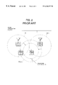
- the base stations B i and B i+1 form adjacent radio zones Z i and Z i+1
- the mobile station T j+1 is located near the periphery of the radio zone Z i+1 and forms a radio zone Z(T j+1 ).
- the mobile station T j belonging to the base station B i receives a signal from the radio zone Z(T j+1 ), and hence makes a request to reduce the radio zone formed by the mobile station T j+1 through the base station B i and a private communication network.
- a transmission signal from the mobile station T j+1 cannot reach the base station B i+1 , and data communication with the base station B i+1 cannot be performed.
- the radio communication system disclosed in Japanese Unexamined Patent Publication No. 2-15740 even when data needs to be transmitted to a specific mobile station, all the mobile stations in the system must be polled, resulting in a very long processing time.
- the radio communication system disclosed in Japanese Unexamined Patent Publication No. 6-29897 is available. In this system, mobile stations are sequentially polled in groups by using idle time for processing other than polling. In this case as well, it takes a very long processing time to poll all the mobile stations.
- the present invention has been made in consideration of the above situation, and has as its object to provide a radio communication system which can perform efficient data communication between base stations and mobile stations by arranging an apparatus capable of specifying the relative positional relationship between the respective base stations and the respective mobile stations.
- a radio communication system which comprises a plurality of base stations and a plurality of mobile stations belonging to service areas covered by radio zones respectively formed by the base stations and performs data communication by polling, each of the plurality of base stations comprising transmission output control means for controlling a transmission output of a polling signal to sequentially form a plurality of radio zones having different coverages, and means for receiving responses from the plurality of mobile stations to a plurality of polling signals having different transmission outputs and determining a position of each of the mobile stations in a specific one of the plurality of radio zones.
- a radio communication system which comprises a plurality of base stations and a plurality of mobile stations belonging to service areas covered by radio zones respectively formed by the base stations and performs data communication by polling, each of the plurality of base stations comprising transmission output control means for controlling a transmission output of a polling signal to alternately transmit a long-distance polling signal having a strong transmission output and a short-distance polling signal having a weak transmission output, thereby alternately forming large and small radio zones, and means for receiving responses from the plurality of mobile stations to the long- and short-distance polling signals and determining a specific one of the large and small zones in which each of the mobile stations is located.
- the first and second main aspects have the following auxiliary aspects.
- Each of the different polling signals has an ID for identifying a base station that has originated the polling signal and a transmission output value.
- the mobile station transmits to a corresponding base station a response signal with an output value corresponding to the transmission output value of a received polling signal.
- the mobile station comprises means for determining, from an ID number of the base station and the transmission output which are obtained by receiving the polling signal, a specific one of the plurality of radio zones in which the mobile station is located and a specific one of the plurality of base stations which forms the radio zone in which the mobile station is located.
- Each of the plurality of base stations continuously transmits only the long-distance polling signal without transmitting the short-distance polling signal when there is no mobile station that responds to the long- and short-distance polling signals.
- Each of the plurality of mobile stations makes no response when the polling signal received following the short-distance polling signal is the long-distance polling signal.
- each of the base stations preferentially transmits the data to a mobile station which is located in the large zone formed by each of the plurality of base stations but is not located in the small zone.
- the small zones respectively formed by the plurality of base stations are arranged such that the small zones formed by the adjacent base stations do not overlap.
- each base station transmits polling signals while controlling their transmission outputs so as to form two radio zones having different sizes, and can independently monitor the respective zones. For this reason, each base station can roughly discriminate the distribution of mobile stations located around the self-station and the relative distances to the respective mobile stations. Therefore, when an information service network for providing appropriate information for each mobile station is to be constructed, more precise information can be provided.
- a mobile station located in a given small zone can communicate with only one base station.
- the base station can therefore provide information unique to itself for the mobile station inside the small zone formed by the base station itself. If the large zones formed by base stations overlap, an area which cannot be covered by any base station can be eliminated in the radio zone.
- control can be performed not to transmit any short-distance polling signal. Therefore, any unnecessary short-distance polling signal need not be transmitted.
- each mobile station can be controlled not to respond to any long-distance polling signal that is received after the reception of a short-distance polling signal
- the mobile stations in the radio zone formed by the base station can be classified into a group located inside the small zone and a group located outside the small zone. If, for example, many mobile stations are present in a radio zone, this grouping can reduce the possibility of interference.
- the data can be transmitted more reliably to the mobile stations which are located outside the small zone and hence may move outside the radio zone of the base station with higher possibility than mobile stations inside the smaller zone.
- FIG. 1 is a schematic view showing an example of the arrangement of a conventional radio communication system
- FIG. 2 is a view for explaining a problem in the prior art
- FIG. 3 is a schematic view showing the arrangement of a radio communication system according to the first embodiment of the present invention.
- FIG. 4 is a block diagram showing the arrangement of a base station in the first embodiment shown in FIG. 3;
- FIG. 5 is a block diagram showing the arrangement of a mobile station according to the first embodiment in FIG. 3;
- FIG. 6 is a timing chart showing how polling signal transmission output control is performed
- FIG. 7 is a view showing a plurality of base stations and the large and small zones formed by the base stations in the present invention.
- FIG. 8 is a view showing an example of the data format of a polling signal
- FIG. 9 is a timing chart showing the output timing of a polling response signal
- FIG. 10 is a view showing an example of the data format of a polling response signal
- FIG. 11 is a timing chart showing how base stations and mobile stations exchange polling signals and polling response signals
- FIG. 12 is a block diagram showing another arrangement of a base station in the present invention.
- FIG. 13 is a block diagram showing another arrangement of a mobile station in the present invention.
- FIG. 14 is a table showing the response determination results obtained by a response determination section in the mobile station in FIG. 13 .
- a radio communication system of the present invention is comprised of base stations B 1 , B 2 , . . . , B n which are fixed or semi-fixed in a movable state and mobile stations T 1 , T 2 , . . . , T m which move inside and outside the radio zones formed by the base stations B 1 , B 2 , . . . , B n.
- Each of the base stations B 1 , B 2 , . . . , B n forms a radio zone by transmitting a polling signal.
- the mobile station makes some response to the base station to notify the base station of the presence of the mobile station.
- the polling signal is temporarily stopped by corresponding communication control, and data communication is performed.
- FIG. 3 shows the first embodiment of the radio communication system of the present invention, and more specifically, adjacent base stations B i and B i+1 , of the base stations B 1 , B 2 , . . . , B n, and mobile stations T j , T j+1 , T j+2 , and T j+3 located around the base stations.
- FIG. 3 does not show base stations other than the base stations B i and B i+1 , and mobile stations other than the mobile stations T j , T j+1 , T j+2 , and T j+3 .
- the base station B i includes an antenna 10 (B i ) for transmitting a polling signal to mobile stations and transmitting/receiving data, a reception section 12 (B i ) for receiving data, a transmission section 13 (B i ) for transmitting a polling signal and data, and a transmission output control section 131 (B i ) for controlling the transmission output of the transmission section 13 (B i ).
- the base station B i further includes a control section 14 (B i ) for controlling the overall base station B i , a mobile station position determination section 15 (B i ) for determining the position of each mobile station in the radio zone in accordance with a response from each mobile station to a polling signal, a polling transmission interval generating timer 17 (B i ) for generating time intervals at which polling signals are transmitted, a switch 11 (B i ) for switching the transmission/reception state of the base station B i under the control of the control section 14 (B i ), and an interface section 19 (B i ) connected to, for example, a network that connects base stations.
- a control section 14 B i
- the base station B i further includes a control section 14 (B i ) for controlling the overall base station B i , a mobile station position determination section 15 (B i ) for determining the position of each mobile station in the radio zone in accordance with a response from each mobile station to a
- the mobile station T j includes an antenna 10 (T j ) for receiving a polling signal from the base station B i and transmitting/receiving data, a reception section 12 (T j ) for receiving a polling signal and data, a transmission section 13 (T j ) for transmitting data, and a pooling response determination section 132 (T j ) for determining whether to respond to a polling signal from the base station B i .
- the mobile station T j further includes a control section 14 (T j ) for controlling the overall mobile station T j , a self-position determination section 16 (T j ) for determining the position of the self-station in the radio zone from the transmission output value obtained from a polling signal from the base station B i , a polling response timing generation timer 18 (T j ) for generating the timing of a response to a polling signal, a switch 11 (T j ) for switching the transmission/reception state of the mobile station T j under the control of the control section 14 (T j ), and an interface section 19 (T j ) connected to a display, input button, or the like.
- a control section 14 T j
- T j for controlling the overall mobile station T j
- a self-position determination section 16 (T j ) for determining the position of the self-station in the radio zone from the transmission output value obtained from a polling signal from the base station B i
- T j polling
- the control section 14 (B i ) controls the polling transmission interval generating timer 17 (B i ) to generate the timing of transmission of a polling signal. In accordance with this timing, the control section 14 (B i ) sends, to the transmission section 13 (B i ), an instruction to transmit a polling signal.
- the control section 14 (B i ) controls the transmission output control section 131 (B i ) to adjust the transmission output of a polling signal, as shown in FIG. 6 .
- FIG. 6 shows a case wherein polling signals are output at predetermined intervals (time ti).
- the control section 14 (B i ) may control the polling transmission interval generating timer 17 (B i ) to transmit polling signals irregularly instead of transmitting them at predetermined intervals.
- the transmission section 13 (B i ) changes the transmission output of a polling signal in accordance with the transmission output value sent from the transmission output control section 131 (B i ), and transmits the polling signal through the switch 11 (B i ) and the antenna 10 (B i ).
- the switch 11 (B i ) has already been switched to the transmission section 13 (B i ) side.
- the switch 11 (B i ) is switched to the transmission side when a polling signal or other data is to be transmitted, but is always switched to the reception side except for such an occasion.
- the base station B i changes the transmission output of a polling signal to transmit a long-distance polling signal having a large transmission output and a short-distance polling signal having a small transmission output, thereby forming a radio zone constituted by a large zone BZ i having a large coverage and a small zone SZ i having a small coverage.
- a radio zone constituted by a large zone BZ i having a large coverage and a small zone SZ i having a small coverage.
- such radio zones are formed such that the small zones SZ i and SZ i+1 formed by the adjacent base stations B i and B i+1 do not overlap.
- FIG. 8 shows an example of the data format of a polling signal transmitted from the base station B i .
- the polling signal is made up of flags indicating the start and end of the polling signal, a base station ID for identifying the base station B i that has originated the polling signal, a transmission output value set when the polling signal is transmitted, and data consisting of other control codes and various information.
- the control section 14 (B i ) generates a polling signal in accordance with this data format and sends it to the transmission section 13 (B i ). This signal is then transmitted through the switch 11 (B i ) and the antenna 10 (B i ).
- the mobile station T j Upon reception of the polling signal from the base station, the mobile station T j processes the polling signal through the control section 14 (T j ) to obtain the base station ID and the transmission output value.
- the control section 14 (T j ) sends the base station ID and the transmission output value to the self-position determination section 16 (T j ).
- the self-position determination section 16 (T j ) processes the base station ID and the transmission output value to check whether the mobile station T j is located in the large or small zone in the radio zone formed by the base station.
- the control section 14 instructs the polling response timing generation timer 18 (T j ) to generate the timing of transmission of a polling response signal.
- the polling response timing generation timer 18 (T j ) generates a response timing td by randomly selecting one of random slots.
- the control section 14 (T j ) generates a polling response signal and sends it to the transmission section 13 (T j ) in accordance with the response timing td. This signal is then transmitted through the switch 11 (T j ) and the antenna 10 (T j ). When a polling response signal or another data is to be transmitted, the switch 11 (T j ) is switched to the transmission side, but is always switched to the reception side except for such an occasion.
- the transmission timing of a polling response signal is set such that a plurality of slots are generated a predetermined period of time after reception of a polling signal, one slot is randomly selected from the generated slots, and the polling response signal is transmitted in the selected slot.
- the time required for the generation of random slots, the number of slots, and the time per slot remain constant throughout all the mobile stations. For this reason, polling response signals do not interfere with each other unless mobile stations that are to respond to the same polling signal select the same slot.
- FIG. 10 shows an example of the data format of a polling response signal.
- the polling response signal is made up of flags indicating the start and end of the polling response signal, a mobile station ID for identifying the mobile station T j that has originated the polling response signal, a base station ID for identifying the base station that has received the polling response signal, and data consisting of other control codes and various information.
- the control section 14 (T j ) generates a polling response signal in accordance with this data format and sends it to the transmission section 13 (T j ). This signal is then transmitted through the switch 11 (T j ) and the antenna 10 (T j ).
- the base station B i Upon reception of the polling response signal from the mobile station, the base station B i processes the polling response signal through the control section 14 (B i ) to obtain the mobile station ID.
- the mobile station position determination section 15 (B i ) checks whether the received polling response signal is a response to a long-distance polling signal or short-distance polling signal, thereby checking whether the mobile station corresponding to the obtained mobile station ID is located inside or outside the small zone SZ i of the radio zone formed by the base station B i .
- FIG. 11 shows how polling signals and polling response signals are exchanged in a case wherein base stations and mobile stations are arranged as shown in FIG. 3 .
- FIG. 11 shows the output levels of the respective signals along the time axis extending to the right.
- the base stations B i and B i+1 alternately originate long-distance polling signals and short-distance polling signals at predetermined time intervals t. At this time, synchronization is not necessarily established between the base stations B i and B i+1 .
- the mobile station T j Since the mobile station T j is located inside the small zone of the base station B i , the mobile station T j receives both short- and long-distance polling signals from the base station B i , and hence responds to them. Since the mobile station T j+1 is located in a place where the large zone of the base station B i overlaps the large zone of the base station B i+1 , the mobile station T j+1 responds to long-distance polling signals from the two base stations. The mobile station T j+2 is located inside the large zone of the base station B i+1 , and hence responds to a long-distance polling signal from the base station B i+1 . The mobile station T j+3 is located outside the radio zones of the two base stations, and hence originates no polling response signal.
- the timing of transmission of a polling response signal is generated by selecting one of random slots through the polling response timing generation timer, the probability that polling response signals responding to the same polling signal interfere with each other is low.
- the output level of each polling response signal is set to be almost equal to that of each long-distance polling signal.
- the output level of a polling response signal may be changed in accordance with the transmission output value contained in a polling signal.
- a polling signal and a polling response signal respectively contain the corresponding base station ID or mobile station ID. For this reason, when these signals are received, specific stations from which the signals originated can be determined. Therefore, the base station can determine whether the mobile station located around the base station is located inside or outside the small zone. The mobile station can also determine, from the received polling signal, the position of itself within a specific zone of a specific base station.
- a given base station may receive a polling signal originated from another base station, since a base station ID is contained in the polling signal, the signal does not interfere with a polling response signal.
- a given mobile station may receive a polling response signal originated from another mobile station, since a mobile station ID is contained in the polling response signal, the signal does not interfere with a polling signal from a base station.
- Information originated from the base station includes various data as well as a polling signal.
- the base station B i transmits first the data to mobile stations located outside the small zone in the radio zone formed by the base station B i on the basis of the determination result obtained by the mobile station position determination section 15 (B i ). After completion of data communication to mobile stations outside the small zone, the base station B i transmits the data to mobile stations inside the small zone.
- FIG. 12 shows another arrangement of a base station in the present invention.
- a mobile station presence determination section 20 (B i ) is added to the arrangement of the base station described above and is connected to the control section 14 (B i ).
- the base station B i alternately transmits long- and short-distance polling signals.
- the mobile station presence determination section 20 (B i ) determines that the mobile station is present inside the large zone formed by the base station B i . Otherwise, the mobile station presence determination section 20 (B i ) determines that the mobile station is not present in the large zone. The mobile station presence determination section 20 (B i ) then sends the corresponding information to the control section 14 (B i ).
- control section 14 (B i ) determines, on the basis of the determination result sent from the mobile station presence determination section 20 (B i ), that the mobile station is not present in the large zone formed by the base station B i , the control section 14 (B i ) stops the origination of a short-distance polling signal, and continuously transmits a long-distance polling signal. If it is determined that the mobile station is present in the large zone, long- and short-distance polling signals are alternately originated, as described above.
- FIG. 13 shows another arrangement of the mobile station in the present invention.
- a response determination section 30 (T j ), a transmission output value buffer 31 (T j ), and a transmission output value determination section 32 (T j ) are added to the arrangement of the above mobile station and are connected to the control section 14 (T j ).
- the control section 14 (T j ) Upon reception of a polling signal from a base station, the control section 14 (T j ) processes the polling signal to obtain the transmission output value of the polling signal in the above-described manner.
- the control section 14 (T j ) sends the transmission output value to the response determination section 30 (T j ).
- the response determination section 30 (T j ) sends the transmission output value sent from the control section 14 (T j ) to the transmission output value buffer 31 (T j ).
- the transmission output value buffer 31 (T j ) includes two transmission output value memories 311 (T j ) and 312 (T j ) capable of storing transmission output values.
- the transmission output value buffer 31 (T j ) Upon reception of a transmission output value from the response determination section 30 (T j ), the transmission output value buffer 31 (T j ) stores the transmission output value, stored in the transmission output value memory 311 (T j ), in the transmission output value memory 312 (T j ), and stores the transmission output value, sent from the response determination section 30 (T j ), in the transmission output value memory 311 (T j ).
- the transmission output value sent from the response determination section 30 (T j ) may be simply stored in the transmission output value memory 311 (T j ). With this operation, the transmission output value of the currently received polling signal and the transmission output value of the previously received polling signal are respectively stored in the transmission output value memories 311 (T j ) and 312 (T j ).
- the response determination section 30 (T j ) clears the transmission output value memories 311 (T j ) and 312 (T j ) in the transmission output value buffer 31 (T j ).
- the transmission output value determination section 32 (T j ) refers to/processes the transmission output value in the transmission output value buffer 31 (T j ) to check whether the polling signal is a long- or short-distance polling signal, and sends the determination result to the response determination section 30 (T j ).
- the response determination section 30 (T j ) generates and outputs a determination result indicating whether to transmit a polling response signal on the basis of the determination result sent form the transmission output value determination section 32 (T j ).
- FIG. 14 shows the determination results sent from the transmission output value determination section 32 (T j ) and the response determination results obtained by the response determination section 30 (T j ).
- the determination results sent from the transmission output value determination section 32 (T j ) are classified into six patterns. Of the six patterns, patterns 1 to 4 correspond to whether the mobile station is located inside the large or small zone in the radio zone formed by the base station.
- Pattern 1 corresponds to a case wherein the mobile station is located inside the large zone of the base station.
- Patterns 2 and 3 correspond to a case wherein the mobile station is located inside the small zone.
- Pattern 4 corresponds to a case wherein the mobile station is located in the small zone but fails to receive a long-distance polling signal for some reason, and the short-distance polling signal received before last is left in the transmission output value buffer 31 (T j ).
- Patterns 5 and 6 correspond to a case wherein the transmission output value buffer 31 (T j ) is empty because, for example, the mobile station is located in an area that does not belong to any of the radio zones of the base stations, and no polling signal is received within a predetermined period of time.
- the response determination section 30 (T j ) determines, on the basis of the determination result obtained by the transmission output value determination section 32 (T j ), a specific pattern, of the six patterns, to which the current and previous polling signals correspond. Assume that the response determination section 30 (T j ) determines pattern 2 , in which the currently received polling signal is a long-distance polling signal and the previously received polling signal is a short-distance polling signal. In this case, a determination result indicating that no response is to be made is output to the control section 14 (T j ).
- a determination result indicating that a polling response signal is to be output to the base station in response to the polling signal is output to the control section 14 (T j ).
- the control section 14 (T j ) controls transmission/non-transmission of a polling response signal.
- the transmission output of a polling signal is controlled in two steps.
- the transmission output of a polling signal may be controlled in three or more steps.
- the propagation of radio waves is influenced by environments, when transmission output control is performed in multiple steps, a distinctive radio zone may not be formed in some case. For this reason, the number of steps must be set within the range in which the boundaries between radio zones remain distinct.
- small zones are formed by base stations such that the small zones formed by the respective adjacent base stations do not overlap, as shown in FIG. 7 .
- the present invention is not limited to this arrangement.
- the sizes of large and small zones can be arbitrarily set in accordance with the system to which the present invention is applied.
- the present invention is effective especially for radio communication using a signal frequency.
Abstract
Description
Claims (8)
Applications Claiming Priority (2)
| Application Number | Priority Date | Filing Date | Title |
|---|---|---|---|
| JP10-098274 | 1998-03-27 | ||
| JP09827498A JP3164209B2 (en) | 1998-03-27 | 1998-03-27 | Wireless communication system |
Publications (1)
| Publication Number | Publication Date |
|---|---|
| US6266537B1 true US6266537B1 (en) | 2001-07-24 |
Family
ID=14215371
Family Applications (1)
| Application Number | Title | Priority Date | Filing Date |
|---|---|---|---|
| US09/280,218 Expired - Fee Related US6266537B1 (en) | 1998-03-27 | 1999-03-29 | Radio communication system |
Country Status (2)
| Country | Link |
|---|---|
| US (1) | US6266537B1 (en) |
| JP (1) | JP3164209B2 (en) |
Cited By (36)
| Publication number | Priority date | Publication date | Assignee | Title |
|---|---|---|---|---|
| US20040032850A1 (en) * | 2002-08-15 | 2004-02-19 | Interdigital Technology Corporation | Maximizing allowable flexible slot-to cell allocation by using adaptive antennas in a TDD system |
| US20040043764A1 (en) * | 2000-04-12 | 2004-03-04 | John Bigham | Intelligent control of radio resources in a wireless network |
| WO2004043015A1 (en) * | 2002-11-05 | 2004-05-21 | Cambridge Consultants Limited | Proximity detector |
| US20040166867A1 (en) * | 2003-02-24 | 2004-08-26 | William Hawe | Program for ascertaining a dynamic attribute of a system |
| US20040235136A1 (en) * | 2001-03-29 | 2004-11-25 | Yogendra Singh | Novel protein molecule useful for inhibition of anthrax toxin |
| US20060040707A1 (en) * | 2004-08-18 | 2006-02-23 | Video54 Technologies, Inc. | System and method for transmission parameter control for an antenna apparatus with selectable elements |
| US7068992B1 (en) * | 1999-12-30 | 2006-06-27 | Motient Communications Inc. | System and method of polling wireless devices having a substantially fixed and/or predesignated geographic location |
| WO2007018864A2 (en) * | 2005-07-26 | 2007-02-15 | Ruckus Wireless, Inc. | Coverage enhancement using dynamic antennas |
| US20070115180A1 (en) * | 2004-08-18 | 2007-05-24 | William Kish | Transmission and reception parameter control |
| EP1814344A1 (en) | 2006-01-31 | 2007-08-01 | Fujitsu Limited | Polling terminals in a single frequency mobile communication system |
| US20070193341A1 (en) * | 2006-02-17 | 2007-08-23 | Kaco Gmbh & Co. Kg | Testing Device for Detecting Vapor Emission of at Least One Leakage Point, Especially of a Mechanical Shaft Seal, Particularly in the Automotive Field |
| US7366169B1 (en) | 2004-02-18 | 2008-04-29 | Autocell Laboratories, Inc. | Apparatus for scanning radio frequency channels |
| US20080123599A1 (en) * | 2005-07-25 | 2008-05-29 | Yoshihito Ishibashi | Communication System, Communication Device And Method, And Program |
| US20080240008A1 (en) * | 2003-02-24 | 2008-10-02 | Floyd Backes | Wireless Network Apparatus and System Field of the Invention |
| US7606573B1 (en) | 2002-09-27 | 2009-10-20 | Autocell Laboratories, Inc. | Wireless switched network |
| US20090280853A1 (en) * | 2008-05-07 | 2009-11-12 | At&T Mobility Ii Llc | Signaling-triggered power adjustment in a femto cell |
| US20090280819A1 (en) * | 2008-05-07 | 2009-11-12 | At&T Mobility Ii Llc | Femto cell signaling gating |
| US20090286540A1 (en) * | 2008-05-13 | 2009-11-19 | At&T Mobility Ii Llc | Femtocell architecture for information management |
| US7623857B1 (en) * | 2005-10-21 | 2009-11-24 | At&T Intellectual Property I, L.P. | Intelligent pico-cell for transport of wireless device communications over wireline networks |
| US20090298470A1 (en) * | 2008-05-13 | 2009-12-03 | At&T Mobility Ii Llc | Administration of access lists for femtocell service |
| US20100027469A1 (en) * | 2008-06-12 | 2010-02-04 | At&T Mobility Ii Llc | Point of sales and customer support for femtocell service and equipment |
| US20100190511A1 (en) * | 2004-11-17 | 2010-07-29 | Qualcomm Incorporated | Method for ambiguity resolution in location determination |
| US20110093913A1 (en) * | 2009-10-15 | 2011-04-21 | At&T Intellectual Property I, L.P. | Management of access to service in an access point |
| US20110119360A1 (en) * | 2009-11-16 | 2011-05-19 | Kish William S | Establishing a Mesh Network with Wired and Wireless Links |
| US20120063337A1 (en) * | 2010-09-13 | 2012-03-15 | Ashish Kumar Shukla | Access point controller for adjusting a wireless access point |
| US8326296B1 (en) | 2006-07-12 | 2012-12-04 | At&T Intellectual Property I, L.P. | Pico-cell extension for cellular network |
| US8355343B2 (en) | 2008-01-11 | 2013-01-15 | Ruckus Wireless, Inc. | Determining associations in a mesh network |
| US8411616B2 (en) | 2005-11-03 | 2013-04-02 | Piccata Fund Limited Liability Company | Pre-scan for wireless channel selection |
| US8547899B2 (en) | 2007-07-28 | 2013-10-01 | Ruckus Wireless, Inc. | Wireless network throughput enhancement through channel aware scheduling |
| US8619662B2 (en) | 2004-11-05 | 2013-12-31 | Ruckus Wireless, Inc. | Unicast to multicast conversion |
| US8634402B2 (en) | 2004-11-05 | 2014-01-21 | Ruckus Wireless, Inc. | Distributed access point for IP based communications |
| US8638708B2 (en) | 2004-11-05 | 2014-01-28 | Ruckus Wireless, Inc. | MAC based mapping in IP based communications |
| US8670725B2 (en) | 2006-08-18 | 2014-03-11 | Ruckus Wireless, Inc. | Closed-loop automatic channel selection |
| US8824357B2 (en) | 2004-11-05 | 2014-09-02 | Ruckus Wireless, Inc. | Throughput enhancement by acknowledgment suppression |
| US9999087B2 (en) | 2009-11-16 | 2018-06-12 | Ruckus Wireless, Inc. | Determining role assignment in a hybrid mesh network |
| CN110691454A (en) * | 2019-09-10 | 2020-01-14 | 四川创宏电气有限公司 | Fire-fighting lamp polling method and emergency lamp control system |
Families Citing this family (2)
| Publication number | Priority date | Publication date | Assignee | Title |
|---|---|---|---|---|
| KR100362163B1 (en) * | 2000-12-13 | 2002-11-23 | 에스케이 텔레콤주식회사 | Analysis method of service coverage in wireless communication system |
| KR100802439B1 (en) * | 2001-11-15 | 2008-02-13 | 에스케이 텔레콤주식회사 | Method for Extension of Cell Coverage for Data Service in UMTS |
Citations (19)
| Publication number | Priority date | Publication date | Assignee | Title |
|---|---|---|---|---|
| JPS63281532A (en) | 1987-05-14 | 1988-11-18 | Nippon Telegr & Teleph Corp <Ntt> | Position registering system |
| JPH0215740A (en) | 1988-07-01 | 1990-01-19 | Nri & Ncc Co Ltd | Data collecting system by radio communication |
| JPH02256332A (en) | 1989-03-29 | 1990-10-17 | Sharp Corp | Radio communication system |
| JPH02272831A (en) | 1989-04-13 | 1990-11-07 | Kokusai Denki Eng:Kk | Distributed base station in mobile radio and mobile radio equipment |
| US4989204A (en) * | 1988-02-10 | 1991-01-29 | Nec Corporation | High throughput communication method and system for a digital mobile station when crossing a zone boundary during a session |
| JPH0629897A (en) | 1992-07-06 | 1994-02-04 | Fujitsu Ten Ltd | Polling method in mobile radio system |
| US5295180A (en) * | 1992-04-08 | 1994-03-15 | U S West Newvector Group, Inc. | Cellular telephone zone system |
| US5345500A (en) * | 1992-07-13 | 1994-09-06 | Motorola, Inc. | Method and apparatus for completing inbound calls in a wireless communication system |
| US5349632A (en) * | 1991-05-20 | 1994-09-20 | Nec Corporation | Cordless telecommunication network with dynamically assigned unique timeslots for zone registration polling |
| JPH08107382A (en) | 1994-10-05 | 1996-04-23 | Tec Corp | Radio communication system |
| US5513243A (en) * | 1992-01-20 | 1996-04-30 | Nec Corporation | Person location system |
| JPH08340573A (en) | 1995-06-13 | 1996-12-24 | Japan Radio Co Ltd | Mobile communication system |
| JPH09182137A (en) | 1995-12-25 | 1997-07-11 | Matsushita Electric Ind Co Ltd | Position register control method for mobile communication system |
| US5896561A (en) * | 1992-04-06 | 1999-04-20 | Intermec Ip Corp. | Communication network having a dormant polling protocol |
| US5910947A (en) * | 1995-09-12 | 1999-06-08 | Toyota Jidosha Kabushiki Kaisha | Mobile unit radio communications system |
| US6026301A (en) * | 1996-12-17 | 2000-02-15 | Northern Telecom Limited | Method for hard handoff in a CDMA cellular environment |
| US6088590A (en) * | 1993-11-01 | 2000-07-11 | Omnipoint Corporation | Method and system for mobile controlled handoff and link maintenance in spread spectrum communication |
| US6108544A (en) * | 1997-05-29 | 2000-08-22 | Motorola, Inc. | Method and apparatus for partial coverage zone selective call communication |
| US6148210A (en) * | 1997-03-12 | 2000-11-14 | Denso Corporation | Personal communication system and technique with zone report feature |
-
1998
- 1998-03-27 JP JP09827498A patent/JP3164209B2/en not_active Expired - Fee Related
-
1999
- 1999-03-29 US US09/280,218 patent/US6266537B1/en not_active Expired - Fee Related
Patent Citations (19)
| Publication number | Priority date | Publication date | Assignee | Title |
|---|---|---|---|---|
| JPS63281532A (en) | 1987-05-14 | 1988-11-18 | Nippon Telegr & Teleph Corp <Ntt> | Position registering system |
| US4989204A (en) * | 1988-02-10 | 1991-01-29 | Nec Corporation | High throughput communication method and system for a digital mobile station when crossing a zone boundary during a session |
| JPH0215740A (en) | 1988-07-01 | 1990-01-19 | Nri & Ncc Co Ltd | Data collecting system by radio communication |
| JPH02256332A (en) | 1989-03-29 | 1990-10-17 | Sharp Corp | Radio communication system |
| JPH02272831A (en) | 1989-04-13 | 1990-11-07 | Kokusai Denki Eng:Kk | Distributed base station in mobile radio and mobile radio equipment |
| US5349632A (en) * | 1991-05-20 | 1994-09-20 | Nec Corporation | Cordless telecommunication network with dynamically assigned unique timeslots for zone registration polling |
| US5513243A (en) * | 1992-01-20 | 1996-04-30 | Nec Corporation | Person location system |
| US5896561A (en) * | 1992-04-06 | 1999-04-20 | Intermec Ip Corp. | Communication network having a dormant polling protocol |
| US5295180A (en) * | 1992-04-08 | 1994-03-15 | U S West Newvector Group, Inc. | Cellular telephone zone system |
| JPH0629897A (en) | 1992-07-06 | 1994-02-04 | Fujitsu Ten Ltd | Polling method in mobile radio system |
| US5345500A (en) * | 1992-07-13 | 1994-09-06 | Motorola, Inc. | Method and apparatus for completing inbound calls in a wireless communication system |
| US6088590A (en) * | 1993-11-01 | 2000-07-11 | Omnipoint Corporation | Method and system for mobile controlled handoff and link maintenance in spread spectrum communication |
| JPH08107382A (en) | 1994-10-05 | 1996-04-23 | Tec Corp | Radio communication system |
| JPH08340573A (en) | 1995-06-13 | 1996-12-24 | Japan Radio Co Ltd | Mobile communication system |
| US5910947A (en) * | 1995-09-12 | 1999-06-08 | Toyota Jidosha Kabushiki Kaisha | Mobile unit radio communications system |
| JPH09182137A (en) | 1995-12-25 | 1997-07-11 | Matsushita Electric Ind Co Ltd | Position register control method for mobile communication system |
| US6026301A (en) * | 1996-12-17 | 2000-02-15 | Northern Telecom Limited | Method for hard handoff in a CDMA cellular environment |
| US6148210A (en) * | 1997-03-12 | 2000-11-14 | Denso Corporation | Personal communication system and technique with zone report feature |
| US6108544A (en) * | 1997-05-29 | 2000-08-22 | Motorola, Inc. | Method and apparatus for partial coverage zone selective call communication |
Non-Patent Citations (1)
| Title |
|---|
| Japanese Office Action issued Apr. 5, 2000 in a related application with English translation of relevant portions. |
Cited By (229)
| Publication number | Priority date | Publication date | Assignee | Title |
|---|---|---|---|---|
| US7068992B1 (en) * | 1999-12-30 | 2006-06-27 | Motient Communications Inc. | System and method of polling wireless devices having a substantially fixed and/or predesignated geographic location |
| US20040043764A1 (en) * | 2000-04-12 | 2004-03-04 | John Bigham | Intelligent control of radio resources in a wireless network |
| US7570956B2 (en) * | 2000-04-12 | 2009-08-04 | Queen Mary & Westfield College | Intelligent control of radio resources in a wireless network |
| US20040235136A1 (en) * | 2001-03-29 | 2004-11-25 | Yogendra Singh | Novel protein molecule useful for inhibition of anthrax toxin |
| US20040032850A1 (en) * | 2002-08-15 | 2004-02-19 | Interdigital Technology Corporation | Maximizing allowable flexible slot-to cell allocation by using adaptive antennas in a TDD system |
| US20060198339A1 (en) * | 2002-08-15 | 2006-09-07 | Interdigital Technology Corporation | Wireless communication method and system for minimizing interference by determining mobile station zone locations and potential conflicts between cell zones |
| US7046655B2 (en) * | 2002-08-15 | 2006-05-16 | Interdigital Technology Corporation | Wireless communication method and system for minimizing interference by determining mobile station zone locations and potential conflicts between cell zones |
| US7606573B1 (en) | 2002-09-27 | 2009-10-20 | Autocell Laboratories, Inc. | Wireless switched network |
| WO2004043015A1 (en) * | 2002-11-05 | 2004-05-21 | Cambridge Consultants Limited | Proximity detector |
| US7206297B2 (en) * | 2003-02-24 | 2007-04-17 | Autocell Laboratories, Inc. | Method for associating access points with stations using bid techniques |
| US7167708B2 (en) | 2003-02-24 | 2007-01-23 | Autocell Laboratories Inc. | Wireless channel selection apparatus including scanning logic |
| US20040166851A1 (en) * | 2003-02-24 | 2004-08-26 | Floyd Backes | Method for adjusting channel interference between access points in a wireless network |
| US20040165555A1 (en) * | 2003-02-24 | 2004-08-26 | Floyd Backes | Program for selecting an optimum access point in a wireless network |
| US20040165548A1 (en) * | 2003-02-24 | 2004-08-26 | Floyd Backes | Method for associating access points with stations using bid techniques |
| US20040166848A1 (en) * | 2003-02-24 | 2004-08-26 | Floyd Backes | Method for selecting an optimum access point in a wireless network on a common channel |
| US20040166846A1 (en) * | 2003-02-24 | 2004-08-26 | Floyd Backes | Program for adjusting channel interference between access points in a wireless network |
| US20040166866A1 (en) * | 2003-02-24 | 2004-08-26 | Floyd Backes | Apparatus for selecting an optimum access point in a wireless network |
| US20040166889A1 (en) * | 2003-02-24 | 2004-08-26 | Floyd Backes | Apparatus for adjusting channel interference between devices in a wireless network |
| US20040166871A1 (en) * | 2003-02-24 | 2004-08-26 | Floyd Backes | Apparatus for self-adjusting power at a wireless station to reduce inter-channel interference |
| US20040166852A1 (en) * | 2003-02-24 | 2004-08-26 | Floyd Backers | Method for associating access points with stations in a wireless network |
| US20040166837A1 (en) * | 2003-02-24 | 2004-08-26 | Floyd Backes | Program for associating access points with stations using bid techniques |
| US20040165549A1 (en) * | 2003-02-24 | 2004-08-26 | Floyd Backes | Program for associating access points with stations in a wireless network |
| US20040165612A1 (en) * | 2003-02-24 | 2004-08-26 | Floyd Backes | Transmission channel selection program |
| US20040166849A1 (en) * | 2003-02-24 | 2004-08-26 | William Hawe | Apparatus for ascertaining a dynamic attribute of a system |
| US20040165557A1 (en) * | 2003-02-24 | 2004-08-26 | Floyd Backes | Wireless channel selection method including scanning logic |
| US20040166870A1 (en) * | 2003-02-24 | 2004-08-26 | Floyd Backes | Distributed protocol for use in a wireless network |
| US20040170140A1 (en) * | 2003-02-24 | 2004-09-02 | Floyd Backes | Method for selecting an optimum access point in a wireless network |
| US20040174852A1 (en) * | 2003-02-24 | 2004-09-09 | Floyd Backes | Wireless network architecture comprising platform dependent and platform independent characteristics |
| WO2004077725A2 (en) * | 2003-02-24 | 2004-09-10 | Autocell Laboratories, Inc. | System, method, and apparatus for associating access points with stations in a wireless network |
| US20040185841A1 (en) * | 2003-02-24 | 2004-09-23 | Floyd Backes | Wireless network architecture |
| US7890131B2 (en) | 2003-02-24 | 2011-02-15 | Autocell Laboratories | Program for adjusting channel interference between devices in a wireless network |
| US20040192300A1 (en) * | 2003-02-24 | 2004-09-30 | Floyd Backes | Transmission channel selection method |
| US20040192279A1 (en) * | 2003-02-24 | 2004-09-30 | Floyd Backes | Program for scanning radio frequency channels |
| US20040190478A1 (en) * | 2003-02-24 | 2004-09-30 | Floyd Backes | Apparatus for selecting an optimum access point in a wireless network on a common channel |
| US20040192325A1 (en) * | 2003-02-24 | 2004-09-30 | Floyd Backes | Wireless network apparatus and system |
| US20040192278A1 (en) * | 2003-02-24 | 2004-09-30 | Floyd Backes | Program for selecting an optimum access point in a wireless network on a common channel |
| US20040202130A1 (en) * | 2003-02-24 | 2004-10-14 | Floyd Backes | Apparatus for associating access points with stations in a wireless network |
| US20040203689A1 (en) * | 2003-02-24 | 2004-10-14 | Floyd Backes | Program for self-adjusting power at a wireless station to reduce inter-channel interference |
| US20040203688A1 (en) * | 2003-02-24 | 2004-10-14 | Floyd Backes | Apparatus for adjusting channel interference between access points in a wireless network |
| US20040166844A1 (en) * | 2003-02-24 | 2004-08-26 | Floyd Backes | Method for self-adjusting power at a wireless station to reduce inter-channel interference |
| US20040235465A1 (en) * | 2003-02-24 | 2004-11-25 | William Hawe | Method for ascertaining a dynamic attribute of a system |
| US20040248580A1 (en) * | 2003-02-24 | 2004-12-09 | Floyd Backes | Transmission channel selection apparatus |
| US20050020266A1 (en) * | 2003-02-24 | 2005-01-27 | Floyd Backes | Distance determination apparatus for use by devices in a wireless network |
| US20050026611A1 (en) * | 2003-02-24 | 2005-02-03 | Floyd Backes | Wireless access point protocol method |
| US20050026610A1 (en) * | 2003-02-24 | 2005-02-03 | Floyd Backes | Method for scanning radio frequency channels |
| US20050070263A1 (en) * | 2003-02-24 | 2005-03-31 | Floyd Backes | Wireless access point protocol logic |
| US20050070264A1 (en) * | 2003-02-24 | 2005-03-31 | Floyd Backes | Distance determination program for use by devices in a wireless network |
| US20050090250A1 (en) * | 2003-02-24 | 2005-04-28 | Floyd Backes | Apparatus for associating access points with stations using bid techniques |
| US20050090241A1 (en) * | 2003-02-24 | 2005-04-28 | Floyd Backes | Wireless network architecture |
| WO2004077725A3 (en) * | 2003-02-24 | 2005-06-23 | Floyd Backes | System, method, and apparatus for associating access points with stations in a wireless network |
| US7869822B2 (en) | 2003-02-24 | 2011-01-11 | Autocell Laboratories, Inc. | Wireless network apparatus and system field of the invention |
| US20040166838A1 (en) * | 2003-02-24 | 2004-08-26 | Floyd Backes | Wireless channel selection program |
| US7047015B2 (en) | 2003-02-24 | 2006-05-16 | Autocell Laboratories, Inc. | Method for ascertaining a dynamic attribute of a system |
| US20040166845A1 (en) * | 2003-02-24 | 2004-08-26 | Floyd Backes | Wireless station protocol program |
| US7076220B2 (en) | 2003-02-24 | 2006-07-11 | Autocell Laboratories, Inc. | Program for scanning radio frequency channels |
| US20040166850A1 (en) * | 2003-02-24 | 2004-08-26 | Floyd Backes | Wireless station protocol apparatus |
| US7116979B2 (en) | 2003-02-24 | 2006-10-03 | Autocell Laboratories, Inc | Wireless channel selection method and system using scanning for identifying access point |
| US7146166B2 (en) | 2003-02-24 | 2006-12-05 | Autocell Laboratories, Inc | Transmission channel selection program |
| US7149519B2 (en) | 2003-02-24 | 2006-12-12 | Autocell Laboratories, Inc. | Transmission channel selection method |
| US7149478B2 (en) | 2003-02-24 | 2006-12-12 | Autocell Laboratories, Inc. | Apparatus for ascertaining a dynamic attribute of a system |
| US7149520B2 (en) | 2003-02-24 | 2006-12-12 | Autocell Laboratories, Inc. | Wireless channel selection program |
| US7149539B2 (en) | 2003-02-24 | 2006-12-12 | Autocell Laboratories, Inc | Program for self-adjusting power at a wireless station to reduce inter-channel interference |
| US7155169B2 (en) | 2003-02-24 | 2006-12-26 | Autocell Laboratories, Inc. | Program for ascertaining a dynamic attribute of a system |
| US7158787B2 (en) | 2003-02-24 | 2007-01-02 | Autocell Laboratories, Inc. | Wireless station protocol method |
| US7167696B2 (en) | 2003-02-24 | 2007-01-23 | Autocell Laboratories, Inc. | Method for scanning radio frequency channels |
| US7221954B2 (en) | 2003-02-24 | 2007-05-22 | Autocell Laboratories, Inc. | Method for adjusting channel interference between access points in a wireless network |
| US8180389B2 (en) | 2003-02-24 | 2012-05-15 | Piccata Fund Limited Liability Company | Apparatus for adjusting channel interference between devices in a wireless network |
| US7200395B2 (en) | 2003-02-24 | 2007-04-03 | Autocell Laboratories, Inc. | Wireless station protocol apparatus |
| US7774013B2 (en) | 2003-02-24 | 2010-08-10 | Autocell Laboratories, Inc. | Program for adjusting channel interference between access points in a wireless network |
| US7215661B2 (en) | 2003-02-24 | 2007-05-08 | Autocell Laboratories, Inc. | Method for associating access points with stations in a wireless network |
| US7215973B2 (en) | 2003-02-24 | 2007-05-08 | Autocell Laboratories Inc. | Apparatus for adjusting channel interference between access points in a wireless network |
| US20090213722A1 (en) * | 2003-02-24 | 2009-08-27 | Floyd Backes | Program for Adjusting Channel Interference between Devices in a Wireless Network |
| US20040166868A1 (en) * | 2003-02-24 | 2004-08-26 | Floyd Backes | Wireless channel selection apparatus including scanning logic |
| US20040190470A1 (en) * | 2003-02-24 | 2004-09-30 | Floyd Backes | Wireless station protocol method |
| US7228149B2 (en) | 2003-02-24 | 2007-06-05 | Autocell Laboratories, Inc. | Method for adjusting channel interference between devices in a wireless network |
| US7236471B2 (en) | 2003-02-24 | 2007-06-26 | Autocell Laboratories Inc | Program for associating access points with stations in a wireless network |
| US7248882B2 (en) | 2003-02-24 | 2007-07-24 | Autocell Laboratories, Inc. | Distance determination apparatus for use devices in a wireless network |
| US7248574B2 (en) | 2003-02-24 | 2007-07-24 | Autocell Laboratories, Inc. | Apparatus for selecting an optimum access point in a wireless network |
| US11916793B2 (en) | 2003-02-24 | 2024-02-27 | Intellectual Ventures Ii Llc | Program for adjusting channel interference between access points in a wireless network |
| US11265787B2 (en) | 2003-02-24 | 2022-03-01 | Intellectual Ventures Ii Llc | Program for adjusting channel interference between access points in a wireless network |
| US10420002B2 (en) | 2003-02-24 | 2019-09-17 | Xenogenic Development Limited Liability Company | Program for adjusting channel interference between access points in a wireless network |
| US7263369B2 (en) | 2003-02-24 | 2007-08-28 | Autocell Laboratories Inc | Distance determination method for use by devices in a wireless network |
| US7274945B2 (en) | 2003-02-24 | 2007-09-25 | Autocell Laboratories Inc. | Transmission channel selection apparatus |
| US7274930B2 (en) | 2003-02-24 | 2007-09-25 | Autocell Laboratories, Inc. | Distance determination program for use by devices in a wireless network |
| US7295537B2 (en) | 2003-02-24 | 2007-11-13 | Autocell Laboratories, Inc. | Method for self-adjusting power at a wireless station to reduce inter-channel interference |
| US7307972B2 (en) | 2003-02-24 | 2007-12-11 | Autocell Laboratories, Inc. | Apparatus for selecting an optimum access point in a wireless network on a common channel |
| US7307976B2 (en) | 2003-02-24 | 2007-12-11 | Autocell Laboratories, Inc. | Program for selecting an optimum access point in a wireless network on a common channel |
| US7346321B2 (en) * | 2003-02-24 | 2008-03-18 | Autocell Laboratories Inc. | Apparatus for associating access points with stations using bid techniques |
| US8532063B1 (en) | 2003-02-24 | 2013-09-10 | Piccata Fund Limited Liability Company | Program for selecting an optimum access point in a wireless network |
| US7366504B2 (en) | 2003-02-24 | 2008-04-29 | Autocell Laboratories, Inc. | Program for associating access points with stations using bid techniques |
| US7366537B2 (en) | 2003-02-24 | 2008-04-29 | Autocell Laboratories, Inc. | Wireless network apparatus and system |
| US7369858B2 (en) | 2003-02-24 | 2008-05-06 | Autocell Laboratories, Inc. | Apparatus for self-adjusting power at a wireless station to reduce inter-channel interference |
| US8725132B1 (en) | 2003-02-24 | 2014-05-13 | Piccata Fund Limited Liability Company | Program for adjusting channel interference between access points in a wireless network |
| US20080240008A1 (en) * | 2003-02-24 | 2008-10-02 | Floyd Backes | Wireless Network Apparatus and System Field of the Invention |
| US7656839B2 (en) | 2003-02-24 | 2010-02-02 | Autocell Laboratories, Inc. | Apparatus for associating access points with stations in a wireless network |
| US7502347B2 (en) | 2003-02-24 | 2009-03-10 | Autocell Laboratories, Inc. | Program for selecting an optimum access point in a wireless network |
| US7505441B2 (en) | 2003-02-24 | 2009-03-17 | Autocell Laboratories, Inc. | Method for selecting an optimum access point in a wireless network on a common channel |
| US7653407B2 (en) | 2003-02-24 | 2010-01-26 | Autocell Laboratories, Inc. | Program for adjusting channel interference between devices in a wireless network |
| US20040165556A1 (en) * | 2003-02-24 | 2004-08-26 | Floyd Backes | Distance determination method for use by devices in a wireless network |
| US7221943B2 (en) | 2003-02-24 | 2007-05-22 | Autocell Laboratories, Inc. | Wireless station protocol program |
| US20040166847A1 (en) * | 2003-02-24 | 2004-08-26 | Floyd Backes | Program for adjusting channel interference between devices in a wireless network |
| US8781487B2 (en) | 2003-02-24 | 2014-07-15 | Piccata Fund Limited Liability Company | Program for distributed channel selection, power adjustment and load balancing decisions in a wireless network |
| US9883443B2 (en) | 2003-02-24 | 2018-01-30 | Xenogenic Development Limited Liability Company | Program for adjusting channel interference between access points in a wireless network |
| US7623862B2 (en) | 2003-02-24 | 2009-11-24 | Autocell Laboratories, Inc. | Distributed protocol for use in a wireless network |
| US20040166867A1 (en) * | 2003-02-24 | 2004-08-26 | William Hawe | Program for ascertaining a dynamic attribute of a system |
| US9019936B2 (en) | 2003-02-24 | 2015-04-28 | Piccata Fund Limited Liability Company | Wireless access point protocol method |
| US7366169B1 (en) | 2004-02-18 | 2008-04-29 | Autocell Laboratories, Inc. | Apparatus for scanning radio frequency channels |
| US9484638B2 (en) | 2004-08-18 | 2016-11-01 | Ruckus Wireless, Inc. | Transmission and reception parameter control |
| US9153876B2 (en) | 2004-08-18 | 2015-10-06 | Ruckus Wireless, Inc. | Transmission and reception parameter control |
| US20070115180A1 (en) * | 2004-08-18 | 2007-05-24 | William Kish | Transmission and reception parameter control |
| US7877113B2 (en) | 2004-08-18 | 2011-01-25 | Ruckus Wireless, Inc. | Transmission parameter control for an antenna apparatus with selectable elements |
| US20060040707A1 (en) * | 2004-08-18 | 2006-02-23 | Video54 Technologies, Inc. | System and method for transmission parameter control for an antenna apparatus with selectable elements |
| US7899497B2 (en) | 2004-08-18 | 2011-03-01 | Ruckus Wireless, Inc. | System and method for transmission parameter control for an antenna apparatus with selectable elements |
| US7933628B2 (en) | 2004-08-18 | 2011-04-26 | Ruckus Wireless, Inc. | Transmission and reception parameter control |
| US20090022066A1 (en) * | 2004-08-18 | 2009-01-22 | Kish William S | Transmission parameter control for an antenna apparatus with selectable elements |
| US8583183B2 (en) | 2004-08-18 | 2013-11-12 | Ruckus Wireless, Inc. | Transmission and reception parameter control |
| US20100091749A1 (en) * | 2004-08-18 | 2010-04-15 | William Kish | Transmission and Reception Parameter Control |
| US10187307B2 (en) | 2004-08-18 | 2019-01-22 | Arris Enterprises Llc | Transmission and reception parameter control |
| US8594734B2 (en) | 2004-08-18 | 2013-11-26 | Ruckus Wireless, Inc. | Transmission and reception parameter control |
| US8824357B2 (en) | 2004-11-05 | 2014-09-02 | Ruckus Wireless, Inc. | Throughput enhancement by acknowledgment suppression |
| US9661475B2 (en) | 2004-11-05 | 2017-05-23 | Ruckus Wireless, Inc. | Distributed access point for IP based communications |
| US9071942B2 (en) | 2004-11-05 | 2015-06-30 | Ruckus Wireless, Inc. | MAC based mapping in IP based communications |
| US8634402B2 (en) | 2004-11-05 | 2014-01-21 | Ruckus Wireless, Inc. | Distributed access point for IP based communications |
| US8619662B2 (en) | 2004-11-05 | 2013-12-31 | Ruckus Wireless, Inc. | Unicast to multicast conversion |
| US9066152B2 (en) | 2004-11-05 | 2015-06-23 | Ruckus Wireless, Inc. | Distributed access point for IP based communications |
| US9019886B2 (en) | 2004-11-05 | 2015-04-28 | Ruckus Wireless, Inc. | Unicast to multicast conversion |
| US9794758B2 (en) | 2004-11-05 | 2017-10-17 | Ruckus Wireless, Inc. | Increasing reliable data throughput in a wireless network |
| US8638708B2 (en) | 2004-11-05 | 2014-01-28 | Ruckus Wireless, Inc. | MAC based mapping in IP based communications |
| US9240868B2 (en) | 2004-11-05 | 2016-01-19 | Ruckus Wireless, Inc. | Increasing reliable data throughput in a wireless network |
| US20100190512A1 (en) * | 2004-11-17 | 2010-07-29 | Qualcomm Incoporated | Method for ambiguity resolution in location determination |
| US20100190511A1 (en) * | 2004-11-17 | 2010-07-29 | Qualcomm Incorporated | Method for ambiguity resolution in location determination |
| US9344161B2 (en) | 2004-12-09 | 2016-05-17 | Ruckus Wireless, Inc. | Coverage enhancement using dynamic antennas and virtual access points |
| US20080123599A1 (en) * | 2005-07-25 | 2008-05-29 | Yoshihito Ishibashi | Communication System, Communication Device And Method, And Program |
| WO2007018864A2 (en) * | 2005-07-26 | 2007-02-15 | Ruckus Wireless, Inc. | Coverage enhancement using dynamic antennas |
| US8792414B2 (en) | 2005-07-26 | 2014-07-29 | Ruckus Wireless, Inc. | Coverage enhancement using dynamic antennas |
| WO2007018864A3 (en) * | 2005-07-26 | 2009-04-16 | Ruckus Wireless Inc | Coverage enhancement using dynamic antennas |
| US7623857B1 (en) * | 2005-10-21 | 2009-11-24 | At&T Intellectual Property I, L.P. | Intelligent pico-cell for transport of wireless device communications over wireline networks |
| US8208431B2 (en) | 2005-10-21 | 2012-06-26 | At&T Intellectual Property I, Lp | Intelligent pico-cell for transport of wireless device communications over wireline networks |
| US20100046490A1 (en) * | 2005-10-21 | 2010-02-25 | At&T Intellectual Property I, L.P. | Intelligent pico-cell for transport of wireless device communications over wireline networks |
| US20100272024A1 (en) * | 2005-10-21 | 2010-10-28 | At&T Intellectual Property I, L.P. | Intelligent pico-cell for transport of wireless device communications over wireline networks |
| US7773572B2 (en) | 2005-10-21 | 2010-08-10 | At&T Intellectual Property I, L.P. | Intelligent pico-cell for transport of wireless device communications over wireline networks |
| US8411616B2 (en) | 2005-11-03 | 2013-04-02 | Piccata Fund Limited Liability Company | Pre-scan for wireless channel selection |
| EP1814344A1 (en) | 2006-01-31 | 2007-08-01 | Fujitsu Limited | Polling terminals in a single frequency mobile communication system |
| US20070177539A1 (en) * | 2006-01-31 | 2007-08-02 | Fujitsu Limited | Mobile communication system |
| US7756076B2 (en) | 2006-01-31 | 2010-07-13 | Fujitsu Limited | Cellular mobile communication system having adjacent base stations each using same frequency for communication between base station and mobile terminals |
| US20070193341A1 (en) * | 2006-02-17 | 2007-08-23 | Kaco Gmbh & Co. Kg | Testing Device for Detecting Vapor Emission of at Least One Leakage Point, Especially of a Mechanical Shaft Seal, Particularly in the Automotive Field |
| US9674679B2 (en) | 2006-07-12 | 2017-06-06 | At&T Intellectual Property I, L.P. | Pico-cell extension for cellular network |
| US8897752B2 (en) | 2006-07-12 | 2014-11-25 | At&T Intellectual Property I, L.P. | Pico-cell extension for cellular network |
| US10149126B2 (en) | 2006-07-12 | 2018-12-04 | At&T Intellectual Property I, L.P. | Pico-cell extension for cellular network |
| US9301113B2 (en) | 2006-07-12 | 2016-03-29 | At&T Intellectual Property I, L.P. | Pico-cell extension for cellular network |
| US8326296B1 (en) | 2006-07-12 | 2012-12-04 | At&T Intellectual Property I, L.P. | Pico-cell extension for cellular network |
| US9780813B2 (en) | 2006-08-18 | 2017-10-03 | Ruckus Wireless, Inc. | Closed-loop automatic channel selection |
| US8670725B2 (en) | 2006-08-18 | 2014-03-11 | Ruckus Wireless, Inc. | Closed-loop automatic channel selection |
| US9271327B2 (en) | 2007-07-28 | 2016-02-23 | Ruckus Wireless, Inc. | Wireless network throughput enhancement through channel aware scheduling |
| US9674862B2 (en) | 2007-07-28 | 2017-06-06 | Ruckus Wireless, Inc. | Wireless network throughput enhancement through channel aware scheduling |
| US8547899B2 (en) | 2007-07-28 | 2013-10-01 | Ruckus Wireless, Inc. | Wireless network throughput enhancement through channel aware scheduling |
| US8355343B2 (en) | 2008-01-11 | 2013-01-15 | Ruckus Wireless, Inc. | Determining associations in a mesh network |
| US8780760B2 (en) | 2008-01-11 | 2014-07-15 | Ruckus Wireless, Inc. | Determining associations in a mesh network |
| US8626223B2 (en) | 2008-05-07 | 2014-01-07 | At&T Mobility Ii Llc | Femto cell signaling gating |
| US20090280819A1 (en) * | 2008-05-07 | 2009-11-12 | At&T Mobility Ii Llc | Femto cell signaling gating |
| US8812049B2 (en) | 2008-05-07 | 2014-08-19 | At&T Mobility Ii Llc | Femto cell signaling gating |
| US20090280853A1 (en) * | 2008-05-07 | 2009-11-12 | At&T Mobility Ii Llc | Signaling-triggered power adjustment in a femto cell |
| US8126496B2 (en) | 2008-05-07 | 2012-02-28 | At&T Mobility Ii Llc | Signaling-triggered power adjustment in a femto cell |
| US8863235B2 (en) | 2008-05-13 | 2014-10-14 | At&T Mobility Ii Llc | Time-dependent white list generation |
| US8331228B2 (en) | 2008-05-13 | 2012-12-11 | At&T Mobility Ii Llc | Exchange of access control lists to manage femto cell coverage |
| US8082353B2 (en) | 2008-05-13 | 2011-12-20 | At&T Mobility Ii Llc | Reciprocal addition of attribute fields in access control lists and profiles for femto cell coverage management |
| US20100027521A1 (en) * | 2008-05-13 | 2010-02-04 | At&T Mobility Ii Llc | Intra-premises content and equipment management in a femtocell network |
| US10499247B2 (en) | 2008-05-13 | 2019-12-03 | At&T Mobility Ii Llc | Administration of access lists for femtocell service |
| US8522312B2 (en) | 2008-05-13 | 2013-08-27 | At&T Mobility Ii Llc | Access control lists and profiles to manage femto cell coverage |
| US8719420B2 (en) | 2008-05-13 | 2014-05-06 | At&T Mobility Ii Llc | Administration of access lists for femtocell service |
| US8094551B2 (en) | 2008-05-13 | 2012-01-10 | At&T Mobility Ii Llc | Exchange of access control lists to manage femto cell coverage |
| US10225733B2 (en) | 2008-05-13 | 2019-03-05 | At&T Mobility Ii Llc | Exchange of access control lists to manage femto cell coverage |
| US8755820B2 (en) | 2008-05-13 | 2014-06-17 | At&T Mobility Ii Llc | Location-based services in a femtocell network |
| US8763082B2 (en) | 2008-05-13 | 2014-06-24 | At&T Mobility Ii Llc | Interactive client management of an access control list |
| US8179847B2 (en) | 2008-05-13 | 2012-05-15 | At&T Mobility Ii Llc | Interactive white list prompting to share content and services associated with a femtocell |
| US20090299788A1 (en) * | 2008-05-13 | 2009-12-03 | At&T Mobility Ii Llc | Commerce and services in a femtocell network |
| US8787342B2 (en) | 2008-05-13 | 2014-07-22 | At&T Mobility Ii Llc | Intra-premises content and equipment management in a femtocell network |
| US20090298470A1 (en) * | 2008-05-13 | 2009-12-03 | At&T Mobility Ii Llc | Administration of access lists for femtocell service |
| US9930526B2 (en) | 2008-05-13 | 2018-03-27 | At&T Mobility Ii Llc | Interface for access management of femto cell coverage |
| US8209745B2 (en) | 2008-05-13 | 2012-06-26 | At&T Mobility Ii Llc | Automatic population of an access control list to manage femto cell coverage |
| US20090288140A1 (en) * | 2008-05-13 | 2009-11-19 | At&T Mobility Ii Llc | Access control lists and profiles to manage femto cell coverage |
| US8850048B2 (en) | 2008-05-13 | 2014-09-30 | At&T Mobility Ii Llc | Reciprocal addition of attribute fields in access control lists and profiles for femto cell coverage management |
| US9877195B2 (en) | 2008-05-13 | 2018-01-23 | At&T Mobility Ii Llc | Location-based services in a femtocell network |
| US20090286540A1 (en) * | 2008-05-13 | 2009-11-19 | At&T Mobility Ii Llc | Femtocell architecture for information management |
| US8490156B2 (en) | 2008-05-13 | 2013-07-16 | At&T Mobility Ii Llc | Interface for access management of FEMTO cell coverage |
| US8219094B2 (en) | 2008-05-13 | 2012-07-10 | At&T Mobility Ii Llc | Location-based services in a femtocell network |
| US20090288139A1 (en) * | 2008-05-13 | 2009-11-19 | At&T Mobility Ii Llc | Interface for access management of femto cell coverage |
| US20090288145A1 (en) * | 2008-05-13 | 2009-11-19 | At&T Mobility Ii Llc | Interactive client management of a white list |
| US9019819B2 (en) | 2008-05-13 | 2015-04-28 | At&T Mobility Ii Llc | Exchange of access control lists to manage femto cell coverage |
| US20090286544A1 (en) * | 2008-05-13 | 2009-11-19 | At&T Mobility Ii Llc | Administration of an access control list to femto cell coverage |
| US20090288144A1 (en) * | 2008-05-13 | 2009-11-19 | At&T Mobility Ii Llc | Time-dependent white list generation |
| US9094891B2 (en) | 2008-05-13 | 2015-07-28 | At&T Mobility Ii Llc | Location-based services in a femtocell network |
| US9155022B2 (en) | 2008-05-13 | 2015-10-06 | At&T Mobility Ii Llc | Interface for access management of FEMTO cell coverage |
| US20090285166A1 (en) * | 2008-05-13 | 2009-11-19 | At&T Mobility Ii Llc | Interactive white list prompting to share content and services associated with a femtocell |
| US20090286510A1 (en) * | 2008-05-13 | 2009-11-19 | At&T Mobility Il Llc | Location-based services in a femtocell network |
| US9775037B2 (en) | 2008-05-13 | 2017-09-26 | At&T Mobility Ii Llc | Intra-premises content and equipment management in a femtocell network |
| US8463296B2 (en) | 2008-05-13 | 2013-06-11 | At&T Mobility Ii Llc | Location-based services in a femtocell network |
| US9775036B2 (en) | 2008-05-13 | 2017-09-26 | At&T Mobility Ii Llc | Access control lists and profiles to manage femto cell coverage |
| US9319964B2 (en) | 2008-05-13 | 2016-04-19 | At&T Mobility Ii Llc | Exchange of access control lists to manage femto cell coverage |
| US20090288152A1 (en) * | 2008-05-13 | 2009-11-19 | At&T Mobility Ii Llc | Automatic population of an access control list to manage femto cell coverage |
| US9369876B2 (en) | 2008-05-13 | 2016-06-14 | At&T Mobility Ii Llc | Location-based services in a femtocell network |
| US9392461B2 (en) | 2008-05-13 | 2016-07-12 | At&T Mobility Ii Llc | Access control lists and profiles to manage femto cell coverage |
| US20090286512A1 (en) * | 2008-05-13 | 2009-11-19 | At&T Mobility Ii Llc | Exchange of access control lists to manage femto cell coverage |
| US9503457B2 (en) | 2008-05-13 | 2016-11-22 | At&T Mobility Ii Llc | Administration of access lists for femtocell service |
| US8254368B2 (en) | 2008-05-13 | 2012-08-28 | At&T Mobility Ii Llc | Femtocell architecture for information management |
| US9538383B2 (en) | 2008-05-13 | 2017-01-03 | At&T Mobility Ii Llc | Interface for access management of femto cell coverage |
| US9584984B2 (en) | 2008-05-13 | 2017-02-28 | At&T Mobility Ii Llc | Reciprocal addition of attribute fields in access control lists and profiles for femto cell coverage management |
| US9591486B2 (en) | 2008-05-13 | 2017-03-07 | At&T Mobility Ii Llc | Intra-premises content and equipment management in a femtocell network |
| US20090286509A1 (en) * | 2008-05-13 | 2009-11-19 | At&T Mobility Ii Llc | Reciprocal addition of attribute fields in access control lists and profiles for femto cell coverage management |
| US8274958B2 (en) | 2008-05-13 | 2012-09-25 | At&T Mobility Ii Llc | Intra-premises content and equipment management in a femtocell network |
| US8743776B2 (en) | 2008-06-12 | 2014-06-03 | At&T Mobility Ii Llc | Point of sales and customer support for femtocell service and equipment |
| US20100041364A1 (en) * | 2008-06-12 | 2010-02-18 | At&T Mobility Ii Llc | Femtocell service registration, activation, and provisioning |
| US9246759B2 (en) | 2008-06-12 | 2016-01-26 | At&T Mobility Ii Llc | Point of sales and customer support for femtocell service and equipment |
| US8942180B2 (en) | 2008-06-12 | 2015-01-27 | At&T Mobility Ii Llc | Point of sales and customer support for femtocell service and equipment |
| US20100041365A1 (en) * | 2008-06-12 | 2010-02-18 | At&T Mobility Ii Llc | Mediation, rating, and billing associated with a femtocell service framework |
| US8655361B2 (en) | 2008-06-12 | 2014-02-18 | At&T Mobility Ii Llc | Femtocell service registration, activation, and provisioning |
| US20100027469A1 (en) * | 2008-06-12 | 2010-02-04 | At&T Mobility Ii Llc | Point of sales and customer support for femtocell service and equipment |
| US8504032B2 (en) | 2008-06-12 | 2013-08-06 | At&T Intellectual Property I, L.P. | Femtocell service registration, activation, and provisioning |
| US20110093913A1 (en) * | 2009-10-15 | 2011-04-21 | At&T Intellectual Property I, L.P. | Management of access to service in an access point |
| US8510801B2 (en) | 2009-10-15 | 2013-08-13 | At&T Intellectual Property I, L.P. | Management of access to service in an access point |
| US8856878B2 (en) | 2009-10-15 | 2014-10-07 | At&T Intellectual Property I, L.P | Management of access to service in an access point |
| US10645582B2 (en) | 2009-10-15 | 2020-05-05 | At&T Intellectual Property I, L.P. | Management of access to service in an access point |
| US9509701B2 (en) | 2009-10-15 | 2016-11-29 | At&T Intellectual Property I, L.P. | Management of access to service in an access point |
| US9999087B2 (en) | 2009-11-16 | 2018-06-12 | Ruckus Wireless, Inc. | Determining role assignment in a hybrid mesh network |
| US9979626B2 (en) | 2009-11-16 | 2018-05-22 | Ruckus Wireless, Inc. | Establishing a mesh network with wired and wireless links |
| US20110119360A1 (en) * | 2009-11-16 | 2011-05-19 | Kish William S | Establishing a Mesh Network with Wired and Wireless Links |
| US20120063337A1 (en) * | 2010-09-13 | 2012-03-15 | Ashish Kumar Shukla | Access point controller for adjusting a wireless access point |
| US8811206B2 (en) * | 2010-09-13 | 2014-08-19 | Marvell World Trade Ltd. | Access point controller for adjusting a wireless access point |
| CN110691454A (en) * | 2019-09-10 | 2020-01-14 | 四川创宏电气有限公司 | Fire-fighting lamp polling method and emergency lamp control system |
Also Published As
| Publication number | Publication date |
|---|---|
| JPH11285056A (en) | 1999-10-15 |
| JP3164209B2 (en) | 2001-05-08 |
Similar Documents
| Publication | Publication Date | Title |
|---|---|---|
| US6266537B1 (en) | Radio communication system | |
| EP0283683B1 (en) | Portable wireless communication systems and method | |
| EP1447920B1 (en) | Radio communication method for a wireless local network and a transceiving device | |
| US7299072B2 (en) | Apparatus for time division multi-sector wireless LAN | |
| US4797947A (en) | Microcellular communications system using macrodiversity | |
| EP0539220B1 (en) | Time slot allocation in radio communication system | |
| EP0769884B1 (en) | Method for setting up perch channels in mobile communication by cellular system | |
| EP0709983A1 (en) | Allocation method and apparatus for reusing network resources in a wireless communication system | |
| US8116231B2 (en) | Apparatus and method for enabling discovery of wireless devices | |
| US20020155839A1 (en) | Allocation of control channel in a communication system | |
| JPH03104428A (en) | System for constituting mobile communication radio control channel | |
| JP2000138632A (en) | Mobile communication system | |
| KR20010039704A (en) | Radio-network control apparatus and radio-network control method | |
| WO2004105409A1 (en) | Method and apparatus for channel sharing between multiple communication systems | |
| CN103237319A (en) | Method and apparatus of connectivity recovery in a wireless network | |
| KR20110008193A (en) | Method of allocating channel time, method of determining compatible links, and apparatus for processing data | |
| CA2015494C (en) | Mobile telephone system | |
| KR100291613B1 (en) | Master and slaves for use in telecommunication systems and this telecommunication system | |
| US20100142443A1 (en) | Apparatus and method for merging beacon transmission and reception | |
| JP3068369B2 (en) | Wireless zone switching method | |
| JP4260035B2 (en) | Wireless communication system | |
| US5936947A (en) | Mobile communication system and control channel setting method in mobile communication system | |
| GB2322954A (en) | Mobile communication | |
| JP2689671B2 (en) | Mobile communication system | |
| JP2000341737A (en) | Base station selection system |
Legal Events
| Date | Code | Title | Description |
|---|---|---|---|
| AS | Assignment |
Owner name: NEC CORPORATION, JAPAN Free format text: ASSIGNMENT OF ASSIGNORS INTEREST;ASSIGNORS:KASHITANI, ATSUSHI;YAMANAKA, KATSUHIRO;REEL/FRAME:009870/0346 Effective date: 19990315 |
|
| FEPP | Fee payment procedure |
Free format text: PAYOR NUMBER ASSIGNED (ORIGINAL EVENT CODE: ASPN); ENTITY STATUS OF PATENT OWNER: LARGE ENTITY |
|
| FPAY | Fee payment |
Year of fee payment: 4 |
|
| FPAY | Fee payment |
Year of fee payment: 8 |
|
| REMI | Maintenance fee reminder mailed | ||
| LAPS | Lapse for failure to pay maintenance fees | ||
| STCH | Information on status: patent discontinuation |
Free format text: PATENT EXPIRED DUE TO NONPAYMENT OF MAINTENANCE FEES UNDER 37 CFR 1.362 |
|
| FP | Lapsed due to failure to pay maintenance fee |
Effective date: 20130724 |