US6269484B1 - Method and apparatus for de-interlacing interlaced content using motion vectors in compressed video streams - Google Patents
Method and apparatus for de-interlacing interlaced content using motion vectors in compressed video streams Download PDFInfo
- Publication number
- US6269484B1 US6269484B1 US08/876,031 US87603197A US6269484B1 US 6269484 B1 US6269484 B1 US 6269484B1 US 87603197 A US87603197 A US 87603197A US 6269484 B1 US6269484 B1 US 6269484B1
- Authority
- US
- United States
- Prior art keywords
- data
- motion
- interlacing
- block
- picture
- Prior art date
- Legal status (The legal status is an assumption and is not a legal conclusion. Google has not performed a legal analysis and makes no representation as to the accuracy of the status listed.)
- Expired - Lifetime
Links
Images


Classifications
-
- H—ELECTRICITY
- H04—ELECTRIC COMMUNICATION TECHNIQUE
- H04N—PICTORIAL COMMUNICATION, e.g. TELEVISION
- H04N7/00—Television systems
- H04N7/01—Conversion of standards, e.g. involving analogue television standards or digital television standards processed at pixel level
- H04N7/0117—Conversion of standards, e.g. involving analogue television standards or digital television standards processed at pixel level involving conversion of the spatial resolution of the incoming video signal
- H04N7/012—Conversion between an interlaced and a progressive signal
Definitions
- the invention relates generally to methods and devices for de-interlacing video for display on a progressive display and more particularly to methods and apparatus for de-interlacing interlaced content using decoding motion vector data from compressed video streams.
- video images or graphic images must be displayed by sequentially displaying each successive line of pixel data sequentially for a frame of an image.
- One frame of data is typically displayed on the screen 60 times per second.
- interlaced display devices such as television displays, typically display images using even and odd line interlacing.
- a frame of interlaced video consists of one field of even line data and one field of odd line data
- each field is alternately displayed 30 times per second resulting in a complete frame being refreshed 30 times a second.
- progressive displays need to display a complete frame 60 times per second.
- interlaced video is the video input for a progressive display
- video rendering systems have to generate pixel data for scan lines that are not received in time for the next frame update. This process is called de-interlacing.
- de-interlacing When such interlaced signals are received for display on a progressive computer display, picture quality problems can arise especially when motion is occurring in the picture where inferior methods of de-interlacing are used.
- a current video compression standard known as MPEG-2 and hereby incorporated by reference, specifies the compression format and decoding format for interlaced and non-interlaced video picture information.
- MPEG-2 video streams have picture data divided as blocks of data. These blocks of data are referred to as macroblocks in the MPEG-2 standard.
- a macroblock of data is a collection of Y, Cr, Cb (color space) blocks which have common motion parameters. Therefore, a macroblock of data contains a section of the luminance component and spatially corresponding chrominance components.
- a macroblock of data can either refer to source, decoded data or to the corresponding coded data elements.
- a macroblock of data (macroblocks) consists of blocks of 16 pixels by 16 pixels of Y data and 8 by 8, or 16 by 16 pixels of Cr and Cb data in one field or frame of picture data.
- a picture consists of a luminance matrix Y, and two chrominance matrices (Cb and Cr).
- MPEG-2 video streams also include data known as motion vector data that is solely used by a decoder to efficiently decompress the encoded macroblock of data.
- a motion vector referred to herein as a decoding motion vector, is a two-dimensional vector used for motion compensation that provides an offset from a coordinate position in a current picture to the coordinates in a reference picture.
- the decoder uses the decoding motion vector data stream to reference pixel data from frames already decoded so that more compact difference data can be sent instead of absolute data for those referenced pixels or macroblocks.
- the motion vector data is used to decompress the picture data in the video stream.
- zero decoding motion vectors may indicate that there was no change in pixel data from a previously decoded picture.
- Macroblocks can be in either field pictures or frame pictures. When in a field picture it is field predicted. When in a frame picture, it can be field predicted and frame predicted.
- a macroblock of data defined in the MPEG-2 standard includes among other things, macroblock mode data, decoding motion vector data and coded block pattern data.
- Macroblock mode data are bits that are analyzed for de-interlacing purposes.
- macroblock mode data can include bits indicating whether the data is intracoded.
- Coded block pattern data are bits indicating which blocks are coded.
- Intracoded macroblocks are blocks of data that are not temporarily predicted from a previously reconstructed picture.
- Non-intracoded macroblocks have a decoding motion vector(s) and are temporarily predicted from a previously reconstructed picture.
- a picture structure can be either field coded or frame coded.
- the “bob” method displays single fields as frames.
- the missing scan lines are interpolated from available lines in the file making the frame rate the same as the original field rate.
- This is sometimes referred to as intraframe de-interlacing.
- the most often used methods are line repetition, line averaging and edge-adaptive spatial interpolation.
- this de-interlacing method is also not typically used with some form of motion detection so that non-moving images can appear to be blurry from loss of image detail. This can result from inaccurate interpolation of pixel data.
- de-interlacing Another method of de-interlacing is known as motion adaptive filtering wherein different filtering (de-interlacing) strategies or algorithms are used in picture areas with and without motion.
- intraframe de-interlacing is used in picture areas with motion and field merging (weaving) is used in picture areas without motion.
- Coefficients in the adaptive filters are based on motion detection functions.
- Such systems typically have to determine motion on a pixel by pixel basis from decoded picture information. This can add unnecessary computation time and cost. This is equivalent to using different filtering methods on different picture areas. Additional discussion on video processing techniques can be found in a book entitled “Digital Video Processing,” written by A Murat Tekalp and published by Prentice Hall.
- One proposed type of de-interlacing system for a video stream adds an additional assistance signal in the encoded stream which is then decoded in addition to decoding motion information.
- the additional assistance signal is transmitted to a special decoder in a vertical blanking interval.
- the additional assistance signal enables the decoder to choose from a number of predetermined de-interlacing modes.
- the use of an additional signal requires modification of the encoder and corresponding modification to the decoder.
- de-interlacing system for displaying interlaced content on a progressive display device that does not require the generation and sending of additional information about motion.
- MPEG-2 de-interlacing system that has a comparatively low computation complexity that can cost effectively improve display quality.
- FIG. 1 is a block diagram generally depicting one embodiment of a de-interlacing system using decoding motion vector information in accordance with the invention
- FIG. 2 is a flow diagram generally depicting a method for selectively de-interlacing interlaced video stream data using decoding motion vector information as a basis for determining a method of de-interlacing in accordance with the invention
- FIG. 3 is a more detailed block diagram of the de-interlacing device shown in FIG. 1;
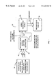
- FIG. 4 is a block diagram generally showing the system of FIG. 1 applied to an MPEG-2 video stream in accordance with the invention
- FIG. 5 is a flow diagram generally depicting a method for de-interlacing interlaced content for display on the progressive display device as carried out by the de-interlacing system shown in FIG. 4;
- FIG. 6 is a flow diagram depicting in more detail steps shown in FIG. 5 for analyzing macroblock of data that are not intracoded;
- FIG. 7 generally illustrates a temporal motion detection filter having a median filter for an additional detection stage in accordance with another embodiment of the invention.
- FIG. 8 generally depicts a system for transitioning between differing de-interlacing methods on horizontally related macroblocks in accordance with the invention.
- FIG. 9 depicts an example of pixel modification in adjacent macroblocks generated by differing interlacing methods to smooth a transition between macroblocks in accordance with the invention.
- the invention provides information to a de-interlacing device. To do this, the invention analyzes information in the encoded stream including motion vector data, and a subset of block of data. The result of the analysis helps to determine the type of de-interlacing to be used.
- Tag information which may be in the form of a bitmap, is created that suggests the best de-interlacing method to use for each block. Bits in the bitmap can be a function of the motion vector data and confidence data reflecting a level of confidence that the referenced data is suitable for use in particular methods of de-interlacing.
- the bitmap is preferably generated by a decoder and transmitted to display hardware that renders the video image by applying the appropriate de-interlacing scheme based on the bitmap data.
- the invention finds particular use in systems having MPEG-2 video streams. However, it will be recognized that the disclosed invention can be used in systems other than those having MPEG-2 video streams. It will also be recognized that the de-interlacing related functions of the decoder and video rendering device may be suitably combined, separated or interchanged as desired.
- FIG. 1 shows generally one embodiment of such a de-interlacing device 50 that receives a compressed data stream 52 from an interlaced picture data encoder 54 , such as a conventional MPEG-2 encoder and outputs de-interlaced picture data 56 through a bus, to a progressive display device 58 .
- a picture can be either a frame or a field.
- the compressed data stream 52 contains encoded interlaced picture data, decoding motion vector data and blocks of data, such as that in an MPEG-2 compressed video stream.
- the de-interlacing device 50 preferably has a compressed data stream decoder 60 with a motion vector extractor that extracts decoding motion vector data from the compressed data stream 52 for use in de-interlacing of decompressed picture data.
- the data stream decoder 60 decodes the interlaced compressed video stream in a conventional manner using decoding motion vector data and outputs decoded interlaced picture data in the form of picture data 62 , as known in the art.
- the data stream decoder 60 performs motion detection by determining, on a block of data by block of data basis, whether each block of data contains motion, based on the decoding motion vector data, for use in de-interlacing.
- the data stream decoder 60 determines the proper de-interlacing method based on the decoding motion vector data and at least a subset of the block of data in stream 52 , such as whether the block of data is intracoded (the type of block of data).
- the data stream decoder 60 also determines and generates decoding motion vector based de-interlacing data 64 , such as a de-interlace bitmap.
- the decoded blocks of picture data 62 and decoding motion vector based de-interlacing data 64 are sent to a video rendering device 66 .
- the video rendering device 66 interprets the motion vector based de-interlacing data 64 and subsequently applies an adaptive motion filtering algorithm to the decoded blocks of picture data 62 containing motion, for display on the progressive display device 58 .
- the decoded blocks of picture data 62 having no motion above a predetermined threshold are de-interlaced using a different de-interlacing method than block of data determined to have motion.
- a block of data may be determined to not have motion if it can not be determined that there was motion above the threshold.
- the data stream decoder 60 extracts the compression motion vector data and generates the decoding motion vector based de-interlacing data 64
- the video rendering device 66 can be suitably modified to carry out the determination and generation (or any part thereof) of the decoding motion vector based de-interlacing data 64
- the decoder can be suitably modified to perform the adaptive motion filtering on a block of data basis and transfer the information to the video rendering device 66 .
- the de-interlacing device 50 may be flexibly implemented through software, hardware or a combination of both. Hence, the new functions of the decoder 60 and the video rendering device 66 as disclosed herein can be implemented through hardware circuitry or through software control.
- FIG. 2 generally illustrates a method for displaying interlaced content on a progressive display device carried out by the de-interlacing device 50 of FIG. 1 .
- the de-interlacing device 50 is enabled to receive the compressed video stream 52 as shown in block 70 .
- the decoder 60 receives the compressed data stream 52 containing an encoded interlaced picture data stream including decoding motion vector data and block of data, as indicated in block 72 .
- the decoder 60 extracts the decoding motion vector data from the compressed data stream for use in both decoding of blocks of data and for later de-interlacing of the decompressed picture data.
- the decoder 60 in combination with the video rendering device 66 selectively de-interlaces the interlaced picture data on a block of data basis.
- the decoder 60 makes this determination based on the decoding motion vector data and at least a subset of the block of data, as shown in block 76 .
- the video rendering device 66 subsequently applies an adaptive motion filtering algorithm to the decoded block of picture data 62 . This is done for each block of data in a frame (or field).
- the adaptive motion filtering algorithm for de-interlacing includes the step of de-interlacing by applying a first de-interlacing technique for block of data containing motion and a second de-interlacing technique for block of data determined to contain no motion.
- the progressive display device 58 then receives the de-interlaced picture data from the video rendering device 66 and displays the de-interlaced picture data as shown in block 78 . This process is repeated for each picture frame (or field) transmitted in the video stream 52 , as shown in block 80 .
- the step of applying an adaptive motion filtering algorithm can be done using a variety of known algorithms. For example, where the de-interlacing device 50 determines that a block does not have motion, a conventional field merging technique can be used. Where the de-interlacing device 50 determines that block has motion, an intraframe de-interlacing technique may be used so that missing lines are interpolated from available lines in a field. Any suitable method of intraframe de-interlacing such as line repetition, line averaging and edge-adaptive spatial interpolation may be used. It will be recognized that hardware or software limitations may prohibit one or more of the techniques from being used. If a determination cannot be made, the video rendering device may attempt to make a determination through some other mechanism or may default to a particular de-interlacing method.
- FIG. 3 shows a more detailed block diagram of the decoder 60 shown in FIG. 1 .
- the decoder 60 includes a conventional decoding block 82 , a conventional motion vector extractor 84 for extracting decoding motion vector bits from the compressed stream 52 , and a decoding motion vector based de-interlacing determinator and bitmap generator 86 .
- motion vector extractor 84 extracts decoding motion vector data 88 which is used by the decoding block 82 to predict missing picture data as known in the art.
- the decoder block 82 serves as the entire decoder except for the decoding motion vector extraction section.
- the decoding motion vector data 88 also serves as an input to the motion vector based de-interlacing determinator and bitmap generator 86 .
- a subset of decoded block of data 90 is also input into the decoding motion vector based de-interlacing determinator and bitmap generator 86 .
- the subset of block of data 90 includes a bit indicating the type of block of data, such as if the block of data is intracoded and block data itself. Also, as further described below, the subset of data can also include other data that provides a level of confidence that the referenced data is useful in de-interlacing.
- the decoding motion vector based de-interlacing determinator and bitmap generator 86 evaluates each block of data to determine whether that block of data has motion as described below.
- Bitmap data 64 is generated for each block of data evaluated. A bit is assigned to each block of data to indicate whether that block of picture data contains motion. In a preferred embodiment a “1” is used to indicate that motion exists for a block of picture data, and a “0” is used to indicate that no motion has been determined for a block of picture data.
- the bitmap data 64 containing motion detection bit information resultant from the evaluation is sent to the video rendering device 66 where it is processed to select how each block of data is de-interlaced. Hence, the selective de-interlacing is done in response to the corresponding bit value from the bitmap data 64 for that block of data.
- bitmap can take any suitable form.
- a bitmap as used herein includes any format of data including table data, tag data or any data used by the de-interlacing mechanism to effect de-interlacing.
- bitmap information may also be a function of motion vector values (or the existence/non-existence of motion vectors) and confidence level information that the referenced block is suitable for use in particular methods of de-interlacing.
- FIG. 4 shows a block diagram of a more particularized de-interlacing device from that shown in FIGS. 1 and 3.
- the compressed video stream is an MPEG-2 video stream, therefore the block of data is a macroblock.
- an MPEG-2 encoder 100 encodes interlaced picture data according to the MPEG-2 standard.
- the encoded compressed MPEG-2 video stream 102 is transmitted to an MPEG-2 de-interlacing device 104 that is substantially identical to the de-interlacing device 50 (see FIG. 1 and FIG. 2) but that the data stream is an MPEG-2 type video stream so that the decoding mechanism and stream information is tailored for MPEG-2 video streams.
- the de-interlacing device 104 includes an MPEG-2 data stream decoder 106 with a standard MPEG-2 decoding block 107 and a decoding motion vector data extraction unit.
- the MPEG-2 data stream decoder 106 also includes a decoding motion vector based de-interlacing determinator 108 and motion vector based de-interlacing bitmap 110 .
- the MPEG-2 data stream decoder 106 conventionally extracts the decoding motion vector data and decodes MPEG-2 picture data.
- the MPEG-2 decoder stage 107 with motion vector extractor outputs macroblock subset information 112 , such as macroblock mode data, and decoding motion vector data 114 to the motion vector based de-interlacing determinator 108 as shown.
- the motion vector based de-interlacing determinator 108 analyzes block mode data, such as the type of macroblock, in the subset of the block of data to determine whether the block of data is intracoded and further analyzes the decoding motion vector to determine whether an associated block of data contains picture data that has motion. If intracoded, the macroblock is designated as having motion except when it is in an “I” picture. Therefore, like the motion vector based de-interlacing determinator and bitmap generator 86 (see FIG. 3 ), the motion vector based de-interlacing determinator 108 generates motion vector based de-interlacing bitmap 110 which contains bit representations of whether each macroblock contains motion or no motion for a given picture.
- the MPEG-2 decoder with motion vector extractor 107 decodes compressed macroblocks of data and outputs decompressed macroblocks of data 116 , which is the macroblock picture data, to the de-interlacing video rendering unit 118 .
- the de-interlacing video rendering unit 118 is substantially identical to the video rendering device 66 of FIGS. 1 and 3, but that the video stream is an MPEG-2 video stream. Therefore, the video rendering unit 118 uses the bitmap data 110 to determine how to apply adaptive motion filtering on a macroblock by macroblock basis to de-interlace picture data. The de-interlaced data is then output for display on progressive display 58 .
- the process starts in block 120 with the MPEG-2 de-interlacing device 104 enabled for operation.
- the MPEG-2 decoder stage 106 receives MPEG-2 compressed data stream with macroblocks of data through decoder 107 .
- the decoding motion vector data is extracted as shown in block 124 .
- the decoding motion vector data is used in a conventional manner to decompress macroblock of data, but unlike conventional MPEG-2 decoders, is also routed to the motion vector based de-interlacing determinator 108 for use in de-interlacing.
- the MPEG-2 decoder 106 analyzes a subset 112 of the macroblocks of data to determine the type of macroblock received as shown in block 126 . Analyzing preferably takes place in the motion vector based de-interlacing determinator 108 . Each macroblock is analyzed to determine whether or not it contains motion. The process begins at block 128 where a macroblock type code bit in the video stream is read to determine if the macroblock of data is intracoded.
- the motion vector based de-interlacing determinator 108 checks to see from the video bit stream whether the macroblock picture data is an “I” picture as shown in block 130 . This is because in MPEG-2 video streams, if a macroblock is intracoded and defined as an “I” picture, there is no data for that macroblock that could suggest whether there is motion in the macroblock. All macroblocks in “I” pictures are intracoded. Also, the determinator 108 must determine whether or not the “I” picture is the initial picture in a sequence as shown in block 132 .
- an initialization bit is set as shown in block 134 and bitmap data generation is started. If the macroblock of data is intracoded and the picture data is not “I” picture information, a 1 is set in the bitmap for this macroblock to indicate motion as shown in block 136 . The process is repeated for each macroblock until the complete motion vector based de-interlacing bitmap data is finalized as indicated in block 138 .
- the motion vector based de-interlacing determinator 108 assumes that the macroblock of data is the same type as a corresponding previous picture macroblock as shown in block 140 .
- FIG. 1 Other picture types in an MPEG-2 based system include “P” pictures and “B” pictures.
- the “P” pictures have macroblocks that are either intracoded or forward predicted.
- the “B” pictures have macroblocks that are intracoded, forward predicted, backward predicted or forward and backward predicted. If the macroblock is not intracoded, a motion vector based de-interlacing determinator 108 analyzes up to four motion vectors in an effort to determine whether or not motion has occurred in the instant macroblock as shown in block 142 . Based upon the MPEG-2 standard, there can be up to four motion vectors depending on the type of motion prediction used by the encoder.
- the motion vector based de-interlacing determinator 108 checks to see if any motion vectors are outside a preset threshold as shown in block 144 .
- the threshold may be set in software to any suitable level. However, it is preferred that the threshold is 1 indicating that any motion will set the bit. If any of the motion vectors are outside the preset threshold, the macroblock is determined to have motion and a 1 is written into the bitmap for that macroblock as shown in block 146 . In block 148 , if no motion vectors are outside the threshold, a 0 is output to the bitmap for that macroblock to indicate there is no motion.
- analyzing decoding motion vector data includes designating the block of data as having motion in response to a comparison of whether the decoding motion vector data is outside of a predetermined threshold.
- FIG. 6 shows a more detailed flow diagram of the steps taken by the motion vector based de-interlacing determinator when the compressed macroblock of data is not intracoded.
- the picture type bit information from the video stream is evaluated as shown in block 150 to determine whether the picture type is a field picture or a frame picture. If the picture type bit information indicates that the picture data is field picture data, the decoder 104 determines whether any motion vector is above a first preset threshold as shown in block 152 .
- the first threshold is preferably 1 indicating any motion sets the bit. If the motion vector is above this preset threshold, a 1 is set in the bitmap to indicate that the macroblock contains motion as shown in block 154 .
- a subset of the macroblock data namely temporal prediction error data (IDCT data) also referred to as difference data, is evaluated to determine confidence data indicating the degree to which the referenced data has motion with respect to the existing block, as shown in block 155 .
- IDCT data temporal prediction error data
- the temporal prediction error data is obtained as a result of inverse discrete cosine transformations (IDCT).
- IDCT inverse discrete cosine transformations
- the confidence level determination may be done by calculating an average absolute value of difference data for each pixel. Other methods may also be used. If the macroblock data would be significantly altered by the IDCT data, a 1 is set in the bitmap indicating that there is not motion for the macroblock as shown in block 157 . If the confidence level data indicates that the referenced data would not materially alter the picture, a 0 is set in the bit map as shown in block 156 . It will be recognized that other suitable information may also be used to determine a confidence level that the referenced data is suitable for de-interlacing.
- the MPEG-2 stream picture type is a frame picture
- additional bits in the video stream are checked to see if the motion type is field based as indicated in block 158 . If the motion type is field based a 1 is set in the bitmap to indicate that there is motion for the frame picture having motion that is field based as shown in block 160 . If however, the motion type is not field based, the MPEG-2 decoder 104 determines whether other information in the video stream can be used, namely whether the difference between the predicted value and the actual value known as temporal prediction error data, is field coded as shown in block 162 .
- the decoder 104 determines whether any motion vector is above a second threshold that is shown in block 166 . It is preferred that this second threshold is about 1. When a motion vector is above the second threshold, the decoder determines that the macroblock has motion and sets a 1 in the bitmap as shown in block 168 . If the motion vector is below the second threshold, confidence data can be determined as shown in blocks 155 - 157 . The confidence data may also be used after other thresholds have been evaluated, such as in FIG. 5 between blocks 144 and 148 .
- FIG. 7 shows an additional detection block 172 for use in the determinator to help eliminate an undesirable alteration between a determination of motion and a determination of no motion when the decoding motion vectors are close to the threshold.
- the additional detection block 172 is a temporal motion detection filter (TDMF) that compares bitmap data (two bits) from two previous pictures to the corresponding bitmap data from the current picture. Of these three bits, the TDMF 172 uses a median filter to determine a final bit value in the bitmap for the current picture.
- TDMF temporal motion detection filter
- the TIDMF 172 receives the a bit 174 from the decoding motion vector based de-interlacing determinator (motion detector stage) 60 and two other bits 176 from stored corresponding bitmap data from the previous picture and the corresponding bitmap data from the picture two pictures prior to the current picture.
- the additional detection block 172 has a conventional median filter that compares the three bits of motion detection to determine whether two or more of the three bits are a “1” or a “0.” Where two or more of the bits are a “1” indicating motion was in at least two of the last corresponding picture frames, a “1” is output to the bitmap for use by the video rendering device. Where two or more of the bits are a “0”, a “0” is output to the bitmap indicating no motion, for use by the video rendering device.
- the TDMF 172 helps correct for random fluctuations in the bitmap data.
- the video rendering device applies an adaptive motion filtering algorithm for de-interlacing includes de-interlacing block of data for display on the progressive display device by inserting picture data line information from the corresponding opposite parity picture (even or odd) into vacant lines in a current block of data that has no motion resulting in a “weave” de-interlacing mode.
- the video rendering device uses adaptive motion filtering to selectively de-interlace the current macroblock by linear averaging the existing picture line data to generate missing line data. This results in one form of “bob” de-interlacing.
- Other types of known algorithms may also be used, such as line repetition and edge-adaptive spatial interpolation.
- de-interlacing device 104 selectively de-interlaces each macroblock using pre-existing decoding motion vector information for two purposes. One to decompress picture data and the other to determine motion to select a proper de-interlacing technique.
- FIG. 8 shows another embodiment of the invention that further improves picture quality wherein a de-interlacing transition determinator stage provides for a smoother transition between motion based and non-motion based methods of de-interlacing for horizontally adjacent macroblocks of data in a picture frame.
- the bitmap data generated from the TMDF 172 serves as input to a de-interlacing transition determinator stage 178 .
- the output from the motion determinator 60 can also serve as the input to the transition determinator 178 .
- motion detection values (bits) from adjacent preceding macroblock (MDn ⁇ 1) and, motion detection values (bits) from a following macroblock (MNDn+1) in the horizontal direction serve as inputs to the de-interlacing transition determinator stage 178 .
- the de-interlacing transition determinator stage 178 compares the motion detection bit data from the horizontally adjacent current, previous and following macroblocks to determine whether a transition from motion to no motion has occurred in horizontally neighboring macroblocks.
- the de-interlacing transition determinator stage 178 generates three bits as outputs.
- One transition bit (T 1 ) indicates that the state of motion in a horizontally preceding macroblock is different from the state of the current macroblock.
- Another transition bit (T 2 ) indicates that the state of a horizontally following macroblock is different from the state of the current macroblock.
- a pixel modification stage 180 blends pixels along edges of macroblocks to smooth out the transition of pixel changes based upon changes in de-interlacing techniques.
- the pixel modification stage 180 modifies pixels based upon the following formula:
- the value V 1 is calculated as if the block has no motion indicating merged pixel de-interlacing.
- the value V 2 is the value of the same pixel as if intraframe de-interlacing is necessary.
- a bitmap representing macroblock motion/non-motion status 184 for a picture is shown 182 .
- An enlarged view of these macroblocks of pixel data shows where the pixels are blended.
- macroblock 186 contains motion, a bob algorithm is used for the lines.
- those pixels along a boundary between transitional macroblocks are blended by weighting values of each of the Y, Cr and Cb luminous (or chromonous) components according to which macroblock they are in.
- Those pixels around the boundary in the motion macroblock are gradually changed to appear as if they underwent merging de-interlacing (no motion) the closer the pixels are to the boundary.
- pixels in the non-motion macroblock are weighted to appear as though they underwent increasing intraframe interlacing the closer the pixels are to the boundary.
- a de-interlacing gradient appears as shown by the arrows 190 such that pixels toward the center of block 186 are weighted to effect more of a motion type de-interlacing technique whereas the pixels toward the center of block 188 are weighted to effect more of a non-motion type de-interlacing technique.
- the disclosed methods and devices may be used in DBS, DVD and other video systems using compressed video streams.
- the disclosed process and devices may be used in more complex video streams that include additional parameters such as MPEG-2 SNR, Spatial and High profiles.
- the bitmap data can be other than binary bitmap data, such that for each macroblock there are more bits indicating the degree of motion. It is therefore contemplated to cover by the present invention, any and all modifications, variations, or equivalents that fall within the spirit and scope of the basic underlying principles disclosed and claimed herein.
Abstract
One embodiment of a de-interlacing device has a decoder that extracts decoding motion vector data for use in de-interlacing of decompressed picture data, from an MPEG-2 type compressed data stream containing interlaced decompressed picture data made up of macroblock of data. The de-interlacing device also has a video rendering device for receiving the extracted decoding motion vector data from the decoder. The decoder has a determinator for determining whether the macroblock of data contains motion based on the decoding motion vector data and at least a subset of the block of data. The decoder generates motion vector based de-interlacing information containing information indicating whether each macroblock contains motion or no motion and if desired, a level of confidence that the referenced data is suitable for a particular method of de-interlacing. The video rendering device de-interlaces the interlaced picture data on a macroblock of data basis by applying an adaptive motion filtering algorithm to the interlaced picture data for display on the progressive display device.
Description
The invention relates generally to methods and devices for de-interlacing video for display on a progressive display and more particularly to methods and apparatus for de-interlacing interlaced content using decoding motion vector data from compressed video streams.
For computer monitors that are mostly non-interlaced or progressive type display devices, video images or graphic images must be displayed by sequentially displaying each successive line of pixel data sequentially for a frame of an image. One frame of data is typically displayed on the screen 60 times per second. In contrast, interlaced display devices, such as television displays, typically display images using even and odd line interlacing. For example, where a frame of interlaced video consists of one field of even line data and one field of odd line data, typically each field is alternately displayed 30 times per second resulting in a complete frame being refreshed 30 times a second. However, progressive displays need to display a complete frame 60 times per second. Therefore when interlaced video is the video input for a progressive display, video rendering systems have to generate pixel data for scan lines that are not received in time for the next frame update. This process is called de-interlacing. When such interlaced signals are received for display on a progressive computer display, picture quality problems can arise especially when motion is occurring in the picture where inferior methods of de-interlacing are used.
The problem exists particularly for personal computers having multimedia capabilities since interlaced video information received from conventional video tapes, cable television broadcasters (CATV), digital video disks (DVD's) and direct broadcast satellite (DBS) systems must be de-interlaced for suitable display on a progressive (non-interlaced based) display device.
A current video compression standard, known as MPEG-2 and hereby incorporated by reference, specifies the compression format and decoding format for interlaced and non-interlaced video picture information. MPEG-2 video streams have picture data divided as blocks of data. These blocks of data are referred to as macroblocks in the MPEG-2 standard. Generally, a macroblock of data is a collection of Y, Cr, Cb (color space) blocks which have common motion parameters. Therefore, a macroblock of data contains a section of the luminance component and spatially corresponding chrominance components. A macroblock of data can either refer to source, decoded data or to the corresponding coded data elements. Typically, a macroblock of data (macroblocks) consists of blocks of 16 pixels by 16 pixels of Y data and 8 by 8, or 16 by 16 pixels of Cr and Cb data in one field or frame of picture data.
Generally, in MPEG-2 systems, two fields of a frame may be coded separately to form two field pictures. Alternatively, the two fields can be coded together as a frame. This is known generally as a frame picture. Both frame pictures and field pictures may be used in a single video sequence. A picture consists of a luminance matrix Y, and two chrominance matrices (Cb and Cr).
MPEG-2 video streams also include data known as motion vector data that is solely used by a decoder to efficiently decompress the encoded macroblock of data. A motion vector, referred to herein as a decoding motion vector, is a two-dimensional vector used for motion compensation that provides an offset from a coordinate position in a current picture to the coordinates in a reference picture. The decoder uses the decoding motion vector data stream to reference pixel data from frames already decoded so that more compact difference data can be sent instead of absolute data for those referenced pixels or macroblocks. In other words, the motion vector data is used to decompress the picture data in the video stream. Also, zero decoding motion vectors may indicate that there was no change in pixel data from a previously decoded picture.
In MPEG-2 video streams, decoding motion vectors are typically assigned to a high percentage of macroblocks. Macroblocks can be in either field pictures or frame pictures. When in a field picture it is field predicted. When in a frame picture, it can be field predicted and frame predicted.
A macroblock of data defined in the MPEG-2 standard includes among other things, macroblock mode data, decoding motion vector data and coded block pattern data. Macroblock mode data are bits that are analyzed for de-interlacing purposes. For example, macroblock mode data can include bits indicating whether the data is intracoded. Coded block pattern data are bits indicating which blocks are coded.
Intracoded macroblocks are blocks of data that are not temporarily predicted from a previously reconstructed picture. Non-intracoded macroblocks have a decoding motion vector(s) and are temporarily predicted from a previously reconstructed picture. In an MPEG-2 video stream, a picture structure can be either field coded or frame coded.
Several basic ways of de-interlacing interlaced video information include a “weave” method and a “bob” method. With the “weave”, or merge method, successive even and odd fields are merged. Each frame to be displayed is constructed by interleaving the scan lines of a pair of fields. Generally, the result is that the frame rate is one-half the field display rate. This “weave” method is generally most effective with areas of a picture that do not have motion over successive frames because it provides more pixel data detail for non-moving objects. However, when motion does occur, artifacts appear in the form of double images of a moving object. Jagged edges appear around the periphery of a moving object causing poor image quality.
In contrast to the “weave” method, the “bob” method displays single fields as frames. The missing scan lines are interpolated from available lines in the file making the frame rate the same as the original field rate. This is sometimes referred to as intraframe de-interlacing. The most often used methods are line repetition, line averaging and edge-adaptive spatial interpolation. Again, this de-interlacing method is also not typically used with some form of motion detection so that non-moving images can appear to be blurry from loss of image detail. This can result from inaccurate interpolation of pixel data.
Another method of de-interlacing is known as motion adaptive filtering wherein different filtering (de-interlacing) strategies or algorithms are used in picture areas with and without motion. Generally, intraframe de-interlacing is used in picture areas with motion and field merging (weaving) is used in picture areas without motion. Coefficients in the adaptive filters are based on motion detection functions. However, such systems typically have to determine motion on a pixel by pixel basis from decoded picture information. This can add unnecessary computation time and cost. This is equivalent to using different filtering methods on different picture areas. Additional discussion on video processing techniques can be found in a book entitled “Digital Video Processing,” written by A Murat Tekalp and published by Prentice Hall.
One proposed type of de-interlacing system for a video stream adds an additional assistance signal in the encoded stream which is then decoded in addition to decoding motion information. The additional assistance signal is transmitted to a special decoder in a vertical blanking interval. The additional assistance signal enables the decoder to choose from a number of predetermined de-interlacing modes. The use of an additional signal requires modification of the encoder and corresponding modification to the decoder.
Consequently, there exists a need for de-interlacing system for displaying interlaced content on a progressive display device that does not require the generation and sending of additional information about motion. There also exists a need for an MPEG-2 de-interlacing system that has a comparatively low computation complexity that can cost effectively improve display quality. Also, it would be advantageous to have a de-interlacing system for displaying interlaced content on a progressive display device wherein the improved system could be flexibly implemented by using software, hardware or a combination of software and hardware.
The features of the present invention together with the advantages thereof, may be understood by reference to the following description taken in conjunction with the accompanying drawings wherein:
FIG. 1 is a block diagram generally depicting one embodiment of a de-interlacing system using decoding motion vector information in accordance with the invention;
FIG. 2 is a flow diagram generally depicting a method for selectively de-interlacing interlaced video stream data using decoding motion vector information as a basis for determining a method of de-interlacing in accordance with the invention;
FIG. 3 is a more detailed block diagram of the de-interlacing device shown in FIG. 1;
FIG. 4 is a block diagram generally showing the system of FIG. 1 applied to an MPEG-2 video stream in accordance with the invention;
FIG. 5 is a flow diagram generally depicting a method for de-interlacing interlaced content for display on the progressive display device as carried out by the de-interlacing system shown in FIG. 4;
FIG. 6 is a flow diagram depicting in more detail steps shown in FIG. 5 for analyzing macroblock of data that are not intracoded;
FIG. 7 generally illustrates a temporal motion detection filter having a median filter for an additional detection stage in accordance with another embodiment of the invention;
FIG. 8 generally depicts a system for transitioning between differing de-interlacing methods on horizontally related macroblocks in accordance with the invention; and
FIG. 9 depicts an example of pixel modification in adjacent macroblocks generated by differing interlacing methods to smooth a transition between macroblocks in accordance with the invention.
The invention provides information to a de-interlacing device. To do this, the invention analyzes information in the encoded stream including motion vector data, and a subset of block of data. The result of the analysis helps to determine the type of de-interlacing to be used. Tag information, which may be in the form of a bitmap, is created that suggests the best de-interlacing method to use for each block. Bits in the bitmap can be a function of the motion vector data and confidence data reflecting a level of confidence that the referenced data is suitable for use in particular methods of de-interlacing. The bitmap is preferably generated by a decoder and transmitted to display hardware that renders the video image by applying the appropriate de-interlacing scheme based on the bitmap data. The invention finds particular use in systems having MPEG-2 video streams. However, it will be recognized that the disclosed invention can be used in systems other than those having MPEG-2 video streams. It will also be recognized that the de-interlacing related functions of the decoder and video rendering device may be suitably combined, separated or interchanged as desired.
FIG. 1 shows generally one embodiment of such a de-interlacing device 50 that receives a compressed data stream 52 from an interlaced picture data encoder 54, such as a conventional MPEG-2 encoder and outputs de-interlaced picture data 56 through a bus, to a progressive display device 58. As used herein, a picture can be either a frame or a field. The compressed data stream 52 contains encoded interlaced picture data, decoding motion vector data and blocks of data, such as that in an MPEG-2 compressed video stream. The de-interlacing device 50 preferably has a compressed data stream decoder 60 with a motion vector extractor that extracts decoding motion vector data from the compressed data stream 52 for use in de-interlacing of decompressed picture data. The data stream decoder 60 decodes the interlaced compressed video stream in a conventional manner using decoding motion vector data and outputs decoded interlaced picture data in the form of picture data 62, as known in the art.
In addition, the data stream decoder 60 performs motion detection by determining, on a block of data by block of data basis, whether each block of data contains motion, based on the decoding motion vector data, for use in de-interlacing. The data stream decoder 60 determines the proper de-interlacing method based on the decoding motion vector data and at least a subset of the block of data in stream 52, such as whether the block of data is intracoded (the type of block of data). The data stream decoder 60 also determines and generates decoding motion vector based de-interlacing data 64, such as a de-interlace bitmap. The decoded blocks of picture data 62 and decoding motion vector based de-interlacing data 64 are sent to a video rendering device 66.
The video rendering device 66 interprets the motion vector based de-interlacing data 64 and subsequently applies an adaptive motion filtering algorithm to the decoded blocks of picture data 62 containing motion, for display on the progressive display device 58. The decoded blocks of picture data 62 having no motion above a predetermined threshold are de-interlaced using a different de-interlacing method than block of data determined to have motion. A block of data may be determined to not have motion if it can not be determined that there was motion above the threshold. Although it is preferred that the data stream decoder 60 extracts the compression motion vector data and generates the decoding motion vector based de-interlacing data 64, it will be recognized by those having ordinary skill in the art, that the video rendering device 66 can be suitably modified to carry out the determination and generation (or any part thereof) of the decoding motion vector based de-interlacing data 64. Also, the decoder can be suitably modified to perform the adaptive motion filtering on a block of data basis and transfer the information to the video rendering device 66.
The de-interlacing device 50 may be flexibly implemented through software, hardware or a combination of both. Hence, the new functions of the decoder 60 and the video rendering device 66 as disclosed herein can be implemented through hardware circuitry or through software control.
FIG. 2, generally illustrates a method for displaying interlaced content on a progressive display device carried out by the de-interlacing device 50 of FIG. 1. Referring to FIGS. 1 and 2, the de-interlacing device 50 is enabled to receive the compressed video stream 52 as shown in block 70. The decoder 60 receives the compressed data stream 52 containing an encoded interlaced picture data stream including decoding motion vector data and block of data, as indicated in block 72. Next, in block 74, the decoder 60 extracts the decoding motion vector data from the compressed data stream for use in both decoding of blocks of data and for later de-interlacing of the decompressed picture data. The decoder 60 in combination with the video rendering device 66 selectively de-interlaces the interlaced picture data on a block of data basis. The decoder 60 makes this determination based on the decoding motion vector data and at least a subset of the block of data, as shown in block 76.
As also shown in block 76, the video rendering device 66 subsequently applies an adaptive motion filtering algorithm to the decoded block of picture data 62. This is done for each block of data in a frame (or field). The adaptive motion filtering algorithm for de-interlacing includes the step of de-interlacing by applying a first de-interlacing technique for block of data containing motion and a second de-interlacing technique for block of data determined to contain no motion.
The progressive display device 58 then receives the de-interlaced picture data from the video rendering device 66 and displays the de-interlaced picture data as shown in block 78. This process is repeated for each picture frame (or field) transmitted in the video stream 52, as shown in block 80.
The step of applying an adaptive motion filtering algorithm, indicated in block 76, can be done using a variety of known algorithms. For example, where the de-interlacing device 50 determines that a block does not have motion, a conventional field merging technique can be used. Where the de-interlacing device 50 determines that block has motion, an intraframe de-interlacing technique may be used so that missing lines are interpolated from available lines in a field. Any suitable method of intraframe de-interlacing such as line repetition, line averaging and edge-adaptive spatial interpolation may be used. It will be recognized that hardware or software limitations may prohibit one or more of the techniques from being used. If a determination cannot be made, the video rendering device may attempt to make a determination through some other mechanism or may default to a particular de-interlacing method.
FIG. 3 shows a more detailed block diagram of the decoder 60 shown in FIG. 1. The decoder 60 includes a conventional decoding block 82, a conventional motion vector extractor 84 for extracting decoding motion vector bits from the compressed stream 52, and a decoding motion vector based de-interlacing determinator and bitmap generator 86. As with conventional block of data decoders, motion vector extractor 84 extracts decoding motion vector data 88 which is used by the decoding block 82 to predict missing picture data as known in the art. Generally, the decoder block 82 serves as the entire decoder except for the decoding motion vector extraction section. The decoding motion vector data 88 also serves as an input to the motion vector based de-interlacing determinator and bitmap generator 86.
In addition to the decoding motion vector data 88, a subset of decoded block of data 90 is also input into the decoding motion vector based de-interlacing determinator and bitmap generator 86. The subset of block of data 90, includes a bit indicating the type of block of data, such as if the block of data is intracoded and block data itself. Also, as further described below, the subset of data can also include other data that provides a level of confidence that the referenced data is useful in de-interlacing.
The decoding motion vector based de-interlacing determinator and bitmap generator 86 evaluates each block of data to determine whether that block of data has motion as described below. Bitmap data 64 is generated for each block of data evaluated. A bit is assigned to each block of data to indicate whether that block of picture data contains motion. In a preferred embodiment a “1” is used to indicate that motion exists for a block of picture data, and a “0” is used to indicate that no motion has been determined for a block of picture data. The bitmap data 64 containing motion detection bit information resultant from the evaluation, is sent to the video rendering device 66 where it is processed to select how each block of data is de-interlaced. Hence, the selective de-interlacing is done in response to the corresponding bit value from the bitmap data 64 for that block of data.
The data in the bitmap can take any suitable form. Hence, a bitmap as used herein includes any format of data including table data, tag data or any data used by the de-interlacing mechanism to effect de-interlacing. In addition to being based on a motion vector value, the bitmap information may also be a function of motion vector values (or the existence/non-existence of motion vectors) and confidence level information that the referenced block is suitable for use in particular methods of de-interlacing.
FIG. 4 shows a block diagram of a more particularized de-interlacing device from that shown in FIGS. 1 and 3. The difference is that the compressed video stream is an MPEG-2 video stream, therefore the block of data is a macroblock. Like the encoder 54 of FIG. 1, an MPEG-2 encoder 100 encodes interlaced picture data according to the MPEG-2 standard. The encoded compressed MPEG-2 video stream 102 is transmitted to an MPEG-2 de-interlacing device 104 that is substantially identical to the de-interlacing device 50 (see FIG. 1 and FIG. 2) but that the data stream is an MPEG-2 type video stream so that the decoding mechanism and stream information is tailored for MPEG-2 video streams.
As with the data stream decoder 60 shown in FIG. 3, the de-interlacing device 104 includes an MPEG-2 data stream decoder 106 with a standard MPEG-2 decoding block 107 and a decoding motion vector data extraction unit. The MPEG-2 data stream decoder 106 also includes a decoding motion vector based de-interlacing determinator 108 and motion vector based de-interlacing bitmap 110. The MPEG-2 data stream decoder 106 conventionally extracts the decoding motion vector data and decodes MPEG-2 picture data.
The MPEG-2 decoder stage 107 with motion vector extractor outputs macroblock subset information 112, such as macroblock mode data, and decoding motion vector data 114 to the motion vector based de-interlacing determinator 108 as shown. The motion vector based de-interlacing determinator 108 analyzes block mode data, such as the type of macroblock, in the subset of the block of data to determine whether the block of data is intracoded and further analyzes the decoding motion vector to determine whether an associated block of data contains picture data that has motion. If intracoded, the macroblock is designated as having motion except when it is in an “I” picture. Therefore, like the motion vector based de-interlacing determinator and bitmap generator 86 (see FIG. 3), the motion vector based de-interlacing determinator 108 generates motion vector based de-interlacing bitmap 110 which contains bit representations of whether each macroblock contains motion or no motion for a given picture.
Also, the MPEG-2 decoder with motion vector extractor 107 decodes compressed macroblocks of data and outputs decompressed macroblocks of data 116, which is the macroblock picture data, to the de-interlacing video rendering unit 118. The de-interlacing video rendering unit 118 is substantially identical to the video rendering device 66 of FIGS. 1 and 3, but that the video stream is an MPEG-2 video stream. Therefore, the video rendering unit 118 uses the bitmap data 110 to determine how to apply adaptive motion filtering on a macroblock by macroblock basis to de-interlace picture data. The de-interlaced data is then output for display on progressive display 58.
Referring to FIGS. 4 and 5, a more detailed description of the operation of the de-interlacing device 104 for an MPEG-2 video stream will now be discussed. The process starts in block 120 with the MPEG-2 de-interlacing device 104 enabled for operation. In block 122, the MPEG-2 decoder stage 106 receives MPEG-2 compressed data stream with macroblocks of data through decoder 107. As with conventional MPEG-2 decoders, the decoding motion vector data is extracted as shown in block 124. The decoding motion vector data is used in a conventional manner to decompress macroblock of data, but unlike conventional MPEG-2 decoders, is also routed to the motion vector based de-interlacing determinator 108 for use in de-interlacing. The MPEG-2 decoder 106 analyzes a subset 112 of the macroblocks of data to determine the type of macroblock received as shown in block 126. Analyzing preferably takes place in the motion vector based de-interlacing determinator 108. Each macroblock is analyzed to determine whether or not it contains motion. The process begins at block 128 where a macroblock type code bit in the video stream is read to determine if the macroblock of data is intracoded.
As a preliminary operation, the motion vector based de-interlacing determinator 108 checks to see from the video bit stream whether the macroblock picture data is an “I” picture as shown in block 130. This is because in MPEG-2 video streams, if a macroblock is intracoded and defined as an “I” picture, there is no data for that macroblock that could suggest whether there is motion in the macroblock. All macroblocks in “I” pictures are intracoded. Also, the determinator 108 must determine whether or not the “I” picture is the initial picture in a sequence as shown in block 132.
If the macroblock of data is intracoded and is in the initial picture in the sequence of an “I” picture, an initialization bit is set as shown in block 134 and bitmap data generation is started. If the macroblock of data is intracoded and the picture data is not “I” picture information, a 1 is set in the bitmap for this macroblock to indicate motion as shown in block 136. The process is repeated for each macroblock until the complete motion vector based de-interlacing bitmap data is finalized as indicated in block 138. If the macroblock of data is intracoded and it is an “I” picture but is not an initial picture in a sequence, then the motion vector based de-interlacing determinator 108 assumes that the macroblock of data is the same type as a corresponding previous picture macroblock as shown in block 140.
Other picture types in an MPEG-2 based system include “P” pictures and “B” pictures. The “P” pictures have macroblocks that are either intracoded or forward predicted. The “B” pictures have macroblocks that are intracoded, forward predicted, backward predicted or forward and backward predicted. If the macroblock is not intracoded, a motion vector based de-interlacing determinator 108 analyzes up to four motion vectors in an effort to determine whether or not motion has occurred in the instant macroblock as shown in block 142. Based upon the MPEG-2 standard, there can be up to four motion vectors depending on the type of motion prediction used by the encoder. In analyzing multiple motion vectors for de-interlacing purposes, the motion vector based de-interlacing determinator 108 checks to see if any motion vectors are outside a preset threshold as shown in block 144. The threshold may be set in software to any suitable level. However, it is preferred that the threshold is 1 indicating that any motion will set the bit. If any of the motion vectors are outside the preset threshold, the macroblock is determined to have motion and a 1 is written into the bitmap for that macroblock as shown in block 146. In block 148, if no motion vectors are outside the threshold, a 0 is output to the bitmap for that macroblock to indicate there is no motion. Hence, analyzing decoding motion vector data includes designating the block of data as having motion in response to a comparison of whether the decoding motion vector data is outside of a predetermined threshold.
FIG. 6 shows a more detailed flow diagram of the steps taken by the motion vector based de-interlacing determinator when the compressed macroblock of data is not intracoded. When the compressed macroblock of data is not intracoded, the picture type bit information from the video stream is evaluated as shown in block 150 to determine whether the picture type is a field picture or a frame picture. If the picture type bit information indicates that the picture data is field picture data, the decoder 104 determines whether any motion vector is above a first preset threshold as shown in block 152. The first threshold is preferably 1 indicating any motion sets the bit. If the motion vector is above this preset threshold, a 1 is set in the bitmap to indicate that the macroblock contains motion as shown in block 154. If however, the motion vector data is below the first threshold for the picture field, a subset of the macroblock data, namely temporal prediction error data (IDCT data) also referred to as difference data, is evaluated to determine confidence data indicating the degree to which the referenced data has motion with respect to the existing block, as shown in block 155. When coded, the temporal prediction error data is obtained as a result of inverse discrete cosine transformations (IDCT). The confidence data is also used to determine a suitable method for de-interlacing.
The confidence level determination may be done by calculating an average absolute value of difference data for each pixel. Other methods may also be used. If the macroblock data would be significantly altered by the IDCT data, a 1 is set in the bitmap indicating that there is not motion for the macroblock as shown in block 157. If the confidence level data indicates that the referenced data would not materially alter the picture, a 0 is set in the bit map as shown in block 156. It will be recognized that other suitable information may also be used to determine a confidence level that the referenced data is suitable for de-interlacing.
Returning to block 150, if the MPEG-2 stream picture type is a frame picture, additional bits in the video stream are checked to see if the motion type is field based as indicated in block 158. If the motion type is field based a 1 is set in the bitmap to indicate that there is motion for the frame picture having motion that is field based as shown in block 160. If however, the motion type is not field based, the MPEG-2 decoder 104 determines whether other information in the video stream can be used, namely whether the difference between the predicted value and the actual value known as temporal prediction error data, is field coded as shown in block 162.
If the temporal prediction error data is field coded, a 1 is set in the bitmap to indicate motion is detected. In other words, the system assumes that because the IDCT data is field coded there is likely motion in the macroblock as indicated in block 164. If the temporal prediction error data is not field coded however, the decoder 104 determines whether any motion vector is above a second threshold that is shown in block 166. It is preferred that this second threshold is about 1. When a motion vector is above the second threshold, the decoder determines that the macroblock has motion and sets a 1 in the bitmap as shown in block 168. If the motion vector is below the second threshold, confidence data can be determined as shown in blocks 155-157. The confidence data may also be used after other thresholds have been evaluated, such as in FIG. 5 between blocks 144 and 148.
FIG. 7 shows an additional detection block 172 for use in the determinator to help eliminate an undesirable alteration between a determination of motion and a determination of no motion when the decoding motion vectors are close to the threshold. In essence, the additional detection block 172 is a temporal motion detection filter (TDMF) that compares bitmap data (two bits) from two previous pictures to the corresponding bitmap data from the current picture. Of these three bits, the TDMF 172 uses a median filter to determine a final bit value in the bitmap for the current picture.
As shown, the TIDMF 172 receives the a bit 174 from the decoding motion vector based de-interlacing determinator (motion detector stage) 60 and two other bits 176 from stored corresponding bitmap data from the previous picture and the corresponding bitmap data from the picture two pictures prior to the current picture. In operation, the additional detection block 172 has a conventional median filter that compares the three bits of motion detection to determine whether two or more of the three bits are a “1” or a “0.” Where two or more of the bits are a “1” indicating motion was in at least two of the last corresponding picture frames, a “1” is output to the bitmap for use by the video rendering device. Where two or more of the bits are a “0”, a “0” is output to the bitmap indicating no motion, for use by the video rendering device. The TDMF 172 helps correct for random fluctuations in the bitmap data.
Once the motion vector based de-interlacing bitmap is complete, the video rendering device applies an adaptive motion filtering algorithm for de-interlacing includes de-interlacing block of data for display on the progressive display device by inserting picture data line information from the corresponding opposite parity picture (even or odd) into vacant lines in a current block of data that has no motion resulting in a “weave” de-interlacing mode. Where the bitmap data indicates that the current macroblock contains motion, the video rendering device uses adaptive motion filtering to selectively de-interlace the current macroblock by linear averaging the existing picture line data to generate missing line data. This results in one form of “bob” de-interlacing. Other types of known algorithms may also be used, such as line repetition and edge-adaptive spatial interpolation. In summary, de-interlacing device 104 selectively de-interlaces each macroblock using pre-existing decoding motion vector information for two purposes. One to decompress picture data and the other to determine motion to select a proper de-interlacing technique.
FIG. 8 shows another embodiment of the invention that further improves picture quality wherein a de-interlacing transition determinator stage provides for a smoother transition between motion based and non-motion based methods of de-interlacing for horizontally adjacent macroblocks of data in a picture frame. Preferably, the bitmap data generated from the TMDF 172 serves as input to a de-interlacing transition determinator stage 178. However, it will be recognized that the output from the motion determinator 60 can also serve as the input to the transition determinator 178. In addition, to the bitmap data, motion detection values (bits) from adjacent preceding macroblock (MDn−1) and, motion detection values (bits) from a following macroblock (MNDn+1) in the horizontal direction serve as inputs to the de-interlacing transition determinator stage 178.
The de-interlacing transition determinator stage 178 compares the motion detection bit data from the horizontally adjacent current, previous and following macroblocks to determine whether a transition from motion to no motion has occurred in horizontally neighboring macroblocks. The de-interlacing transition determinator stage 178 generates three bits as outputs. One transition bit (T1) indicates that the state of motion in a horizontally preceding macroblock is different from the state of the current macroblock. Another transition bit (T2) indicates that the state of a horizontally following macroblock is different from the state of the current macroblock. Based on whether a transition has occurred, a pixel modification stage 180 blends pixels along edges of macroblocks to smooth out the transition of pixel changes based upon changes in de-interlacing techniques.
The pixel modification stage 180 modifies pixels based upon the following formula:
where V1 is calculated as MDn=0 and V2 is calculated as MDn=1, and ALPHA ε[0,1]. The value V1 is calculated as if the block has no motion indicating merged pixel de-interlacing. The value V2 is the value of the same pixel as if intraframe de-interlacing is necessary.
For example, as seen in FIG. 9, a bitmap representing macroblock motion/non-motion status 184 for a picture is shown 182. There is a transition between horizontally adjacent macroblocks 186 and 188. An enlarged view of these macroblocks of pixel data shows where the pixels are blended. Because macroblock 186 contains motion, a bob algorithm is used for the lines. However, those pixels along a boundary between transitional macroblocks are blended by weighting values of each of the Y, Cr and Cb luminous (or chromonous) components according to which macroblock they are in. Those pixels around the boundary in the motion macroblock are gradually changed to appear as if they underwent merging de-interlacing (no motion) the closer the pixels are to the boundary. In contrast, those pixels in the non-motion macroblock are weighted to appear as though they underwent increasing intraframe interlacing the closer the pixels are to the boundary. A de-interlacing gradient appears as shown by the arrows 190 such that pixels toward the center of block 186 are weighted to effect more of a motion type de-interlacing technique whereas the pixels toward the center of block 188 are weighted to effect more of a non-motion type de-interlacing technique.
It should be understood that the implementation of other variations and modifications of the invention in its various aspects will be apparent to those of ordinary skill in the art, and that the invention is not limited by the specific embodiments described. For example, the disclosed methods and devices may be used in DBS, DVD and other video systems using compressed video streams. Also, the disclosed process and devices may be used in more complex video streams that include additional parameters such as MPEG-2 SNR, Spatial and High profiles. Also, it is contemplated that the bitmap data can be other than binary bitmap data, such that for each macroblock there are more bits indicating the degree of motion. It is therefore contemplated to cover by the present invention, any and all modifications, variations, or equivalents that fall within the spirit and scope of the basic underlying principles disclosed and claimed herein.
Claims (20)
1. A method for displaying interlaced content on a progressive display device comprising the steps of:
receiving a compressed data stream of encoded interlaced picture data having decoding motion vector data and picture data in the form of block of data;
extracting the decoding motion vector data from the compressed data stream for use in selecting, prior to a deinterlacing process, at least one of a plurality of adaptive motion filtering algorithms for de-interlacing decompressed picture data; and
selectively de-interlacing the interlaced picture data on a block of data basis by analyzing the decoding motion vector data and at least a subset of the block of data, by selecting at least one of a plurality of adaptive motion filtering algorithms based on analyzed decoding motion vector data and at least a subset of the block of data, and by applying at least one of a selected plurality of adaptive motion filtering algorithms to the interlaced picture data for display on the progressive display device wherein the adaptive motion filtering algorithms employ separable temporal and non-temporal filtering.
2. The method of claim 1 wherein selectively de-interlacing by analyzing the decoding motion vector data and at least a subset of the block of data includes analyzing the decoding motion vector to determine whether an associated block of data contains picture data that has motion and further analyzing block mode data in the subset of the block of data to determine whether the block of data is intracoded and designating the block of data as having motion.
3. The method of claim 2 wherein analyzing decoding motion vector date includes designating the block of data as having motion in response to a comparison of whether the decoding motion vector data is outside of a predetermined threshold.
4. The method of claim 1 wherein applying at least one of the selected plurality of adaptive motion filtering algorithms for selectively de-interlacing includes the step of de-interlacing block of data for display on the progressive display device by inserting picture data line information from a corresponding opposite parity picture into vacant lines in current block of data that has no motion.
5. The method of claim 1 wherein applying at least one of the selected plurality of adaptive motion filtering algorithms for selectively de-interlacing includes the step of de-interlacing block of data for display on the progressive display device by linear averaging of existing picture line data to generate missing lines.
6. The method of claim 1 wherein applying at least one of the selected plurality of adaptive motion filtering algorithms for selectively de-interlacing includes the step of de-interlacing by applying a first selected adaptive motion filtering algorithm for a first block of data containing motion and a second selected adaptive motion filtering algorithm for a second block of data determined to contain no motion.
7. The method of claim 1 further including the step of determining transitions between horizontally adjacent blocks of data by comparing motion detection bit data from horizontally adjacent current, previous and following blocks of data to determine whether a transition from motion to no motion has occurred and modifying pixel information to blend pixels around a boundary of the block of data transition.
8. The method of claim 1 wherein the subset of block data includes confidence data indicating a predetermined confidence level that referenced block of data, to determine a suitable method for de-interlacing, is suitable for de-interlacing.
9. The method of claim 3 wherein the step of designating the block of data includes generating a motion vector based de-interlacing bitmap containing bit information indicating at least one of the plurality of adaptive motion filtering algorithms and whether each block contains motion or no motion.
10. The method of claim 1 wherein the compressed data stream is an MPEG-2 bit stream.
11. The method of claim 8 wherein the block of data is a macroblock and the subset of the macroblock data is IDCT data evaluated to determine confidence data indicating the degree to which referenced data has motion with respect to a macroblock.
12. The method of claim 1 wherein the step of selectively de-interlacing includes the step of generating a de-interlacing bitmap at least based on the motion vector by using a temporal motion detection filter (TDMF) that compares an output from a decoding motion vector based de-interlacing determinator and interlacing bit information from stored corresponding macroblock of data on a previous picture and corresponding macroblock of data on a picture, two pictures prior to the current picture, to determine a final bitmap value for use in de-interlacing.
13. A method for displaying interlaced content on a progressive display device comprising the steps of:
receiving an MPEG-2 compressed data stream of encoded interlaced picture data having decoding motion vector data and macroblock data wherein the picture data is made up of a plurality of macroblock data;
for each macroblock of data, extracting the decoding motion vector data from the compressed data stream for use in selecting, prior to a deinterlacing process, at least one of a plurality of adaptive motion filtering algorithms for de-interlacing decompressed picture data; and
selectively de-interlacing the interlaced picture data on a macroblock of data basis by analyzing the decoding motion vector data and at least a subset of the block of data, by selecting at least one of a plurality of adaptive motion filtering algorithms based on analyzed decoding motion vector data and at least a subset of the block of data, and by applying at least one of a selected plurality of adaptive motion filtering algorithms to the interlaced picture data for display on the progressive display device wherein the adaptive motion filtering algorithms employ separable temporal and non-temporal filtering.
14. The method of claim 13 wherein the step of selectively de-interlacing includes the step of generating a motion vector based de-interlacing bitmap containing bit information indicating whether each macroblock of data contains motion or no motion.
15. The method of claim 14 wherein the plurality of adaptive motion filtering algorithms for selectively de-interlacing include linear averaging existing picture line data to generate missing lines for de-interlacing macroblock of data containing motion and merging by interlacing even and odd fields into a single frame for the macroblock of data containing no motion.
16. The method of claim 13 further including the step of transitioning between de-interlacing algorithms for horizontally aligned macroblock of data in a picture frame wherein one macroblock of data contains motion and an adjacent macroblock of data contains no motion.
17. The method of claim 16 further including the step of determining transitions between horizontally adjacent blocks of data by comparing motion detection bit data from horizontally adjacent current, previous and following blocks of data to determine whether a transition from motion to no motion has occurred and modifying pixel information to blend pixels around a boundary of the block of data transition wherein the step of transitioning includes weighting pixel information.
18. A device for use in displaying interlaced content on a progressive display device comprising:
means for extracting decoding motion vector data for use in selecting, prior to a deinterlacing process, at least one of a plurality of adaptive motion filtering algorithms for de-interlacing decompressed picture data, from a compressed data stream containing interlaced decompressed picture data made up of block of data;
means for receiving the motion vector data from the extracting means having block of data motion detection means for determining whether the block of data contains motion based on the decoding motion vector data; and
means for selectively de-interlacing the interlaced picture data on a block of data basis having means for selecting at least one of a plurality of adaptive motion filtering algorithms by analyzing the motion vector data and at least a subset of the block of data and for applying at least one of a plurality of selected adaptive motion filtering algorithms to the interlaced picture data for display on the progressive display device wherein the adaptive motion filtering algorithms employ separable temporal and non-temporal filtering.
19. The device of claim 18 wherein the means for selecting by analyzing the motion vector data and at least a subset of the block of data generates a de-interlacing bitmap containing bit information indicating at least one of the plurality of selected adaptive motion filtering algorithms for de-interlacing each block of data and whether each block of data contains motion or no motion.
20. The device of claim 18 further including transition detection means for determining transitions between horizontally adjacent blocks of data by comparing motion detection bit data from horizontally adjacent current, previous and following blocks of data to determine whether a transition from motion to no motion has occurred and modifying pixel information to blend pixels around a boundary of the block of data transition.
Priority Applications (1)
| Application Number | Priority Date | Filing Date | Title |
|---|---|---|---|
| US08/876,031 US6269484B1 (en) | 1997-06-24 | 1997-06-24 | Method and apparatus for de-interlacing interlaced content using motion vectors in compressed video streams |
Applications Claiming Priority (1)
| Application Number | Priority Date | Filing Date | Title |
|---|---|---|---|
| US08/876,031 US6269484B1 (en) | 1997-06-24 | 1997-06-24 | Method and apparatus for de-interlacing interlaced content using motion vectors in compressed video streams |
Publications (1)
| Publication Number | Publication Date |
|---|---|
| US6269484B1 true US6269484B1 (en) | 2001-07-31 |
Family
ID=25366838
Family Applications (1)
| Application Number | Title | Priority Date | Filing Date |
|---|---|---|---|
| US08/876,031 Expired - Lifetime US6269484B1 (en) | 1997-06-24 | 1997-06-24 | Method and apparatus for de-interlacing interlaced content using motion vectors in compressed video streams |
Country Status (1)
| Country | Link |
|---|---|
| US (1) | US6269484B1 (en) |
Cited By (69)
| Publication number | Priority date | Publication date | Assignee | Title |
|---|---|---|---|---|
| US20020044217A1 (en) * | 1999-01-05 | 2002-04-18 | Bernd Burchard | Signal processing unit for a digital TV system |
| US20020047919A1 (en) * | 2000-10-20 | 2002-04-25 | Satoshi Kondo | Method and apparatus for deinterlacing |
| US20020051504A1 (en) * | 2000-10-27 | 2002-05-02 | Patrice Onno | Decoding of digital data |
| US20020078440A1 (en) * | 2000-11-27 | 2002-06-20 | Diva Systems Corporation | Method and apparatus for monitoring an information distribution system |
| US20020118297A1 (en) * | 2001-02-28 | 2002-08-29 | Sirilla George Andrew | Method and device for displaying frozen pictures on video display device |
| US20020136540A1 (en) * | 1997-10-06 | 2002-09-26 | Dvdo, Inc. | Digital video system and methods for providing same |
| US6459455B1 (en) * | 1999-08-31 | 2002-10-01 | Intel Corporation | Motion adaptive deinterlacing |
| US6507368B1 (en) * | 1999-01-29 | 2003-01-14 | Canon Kabushiki Kaisha | Control of image signals in liquid crystal displays |
| US6512550B1 (en) * | 1999-06-29 | 2003-01-28 | Lsi Logic Corporation | Motion compensated de-interlacing |
| US20030052995A1 (en) * | 2001-09-14 | 2003-03-20 | Chi-Yuan Hsu | Motion-adaptive de-interlacing method and system for digital televisions |
| US6542196B1 (en) * | 1999-11-05 | 2003-04-01 | Lsi Logic Corporation | Adaptive field pairing system for de-interlacing |
| US6542197B1 (en) * | 1998-06-23 | 2003-04-01 | Samsung Electronics Co., Ltd. | Three-dimensional signal processor using motion information upon decoding image signal |
| US6560286B1 (en) * | 1999-12-29 | 2003-05-06 | Intel Corporation | Field frame motion design for digital video decoder |
| US6567557B1 (en) * | 1999-12-10 | 2003-05-20 | Stmicroelectronics, Inc. | Method for preventing dual-step half-pixel motion compensation accumulation errors in prediction-rich MPEG-2 sequences |
| US20030160895A1 (en) * | 2002-02-25 | 2003-08-28 | Yiwei Wang | Adaptive median filters for de-interlacing |
| US6618094B1 (en) * | 1999-05-25 | 2003-09-09 | Koninklijke Philips Electronics N.V. | De-interlacing image signals |
| US6636267B1 (en) * | 1999-03-24 | 2003-10-21 | Pioneer Corporation | Line interpolation apparatus and line interpolation method |
| KR100403364B1 (en) * | 2001-12-14 | 2003-10-30 | 매크로영상기술(주) | Apparatus and method for deinterlace of video signal |
| WO2003096690A1 (en) * | 2002-05-10 | 2003-11-20 | Thomson Licensing S.A. | Deinterlacing of mixed progressive and non-progressive sequences |
| US6661464B1 (en) * | 2000-11-21 | 2003-12-09 | Dell Products L.P. | Dynamic video de-interlacing |
| US20040037358A1 (en) * | 2000-08-28 | 2004-02-26 | Comer Mary Lafuze | Method and apparatus for motion compensated temporal interpolation of video sequences |
| US20040056978A1 (en) * | 1998-08-11 | 2004-03-25 | Dvdo, Inc. | Method and apparatus for deinterlacing digital video images |
| US20040174459A1 (en) * | 2002-08-30 | 2004-09-09 | Holt Gary R. | Video interlacing using object motion estimation |
| US6842196B1 (en) * | 2000-04-04 | 2005-01-11 | Smith & Nephew, Inc. | Method and system for automatic correction of motion artifacts |
| US20050007490A1 (en) * | 2003-06-30 | 2005-01-13 | Macinnis Alexander G. | Scaling by early deinterlacing |
| EP1357745A3 (en) * | 2002-04-15 | 2005-01-26 | Microsoft Corporation | Method and apparatus for processing of interlaced video images for progressive video displays |
| US20050024363A1 (en) * | 2003-08-01 | 2005-02-03 | Estrop Stephen J. | Bandwidth-efficient processing of video images |
| AU2003264648B2 (en) * | 2002-12-03 | 2005-02-24 | Samsung Electronics Co., Ltd | Deinterlacing apparatus and method |
| US6865283B1 (en) * | 2000-07-31 | 2005-03-08 | Intel Corporation | Communicating information from an imaging device to a processor-based system |
| US20050053365A1 (en) * | 1997-10-06 | 2005-03-10 | Adams Dale R. | Portable DVD player |
| US20050062892A1 (en) * | 1998-07-23 | 2005-03-24 | Dvdo, Inc. | Method and apparatus for reducing on-chip memory in vertical video processing |
| US20050063586A1 (en) * | 2003-08-01 | 2005-03-24 | Microsoft Corporation | Image processing using linear light values and other image processing improvements |
| US6873655B2 (en) | 2001-01-09 | 2005-03-29 | Thomson Licensing A.A. | Codec system and method for spatially scalable video data |
| US20050105683A1 (en) * | 2003-11-14 | 2005-05-19 | Kazuhiko Sato | Computer aided image acquisition and diagnosis system |
| US20050110902A1 (en) * | 2003-11-22 | 2005-05-26 | Seung-Joon Yang | De-interlacing apparatus with a noise reduction/removal device |
| US20050151879A1 (en) * | 2004-01-13 | 2005-07-14 | Yueyong Chen | Method for line average differences based de-interlacing |
| US20050163219A1 (en) * | 2004-01-13 | 2005-07-28 | Ali Corporation | Method for motion vector de-interlacing |
| US20050162563A1 (en) * | 1999-08-11 | 2005-07-28 | Adams Dale R. | Interlace motion artifact detection using vertical frequency detection and analysis |
| US20050168653A1 (en) * | 2004-01-30 | 2005-08-04 | Wyman Richard H. | Reverse pull-down video using corrective techniques |
| US20050168652A1 (en) * | 2004-01-30 | 2005-08-04 | Wyman Richard H. | Detection and phase lock of pull-down video |
| US20050179814A1 (en) * | 2000-05-05 | 2005-08-18 | Stmicroelectronics S.R.I. | Method and system for de-interlacing digital images, and computer program product therefor |
| US20050196052A1 (en) * | 2004-03-02 | 2005-09-08 | Jun Xin | System and method for joint de-interlacing and down-sampling using adaptive frame and field filtering |
| US20050226328A1 (en) * | 2004-03-31 | 2005-10-13 | Raju Hormis | Shared logic for decoding and deinterlacing of compressed video |
| US20050259741A1 (en) * | 2004-05-21 | 2005-11-24 | Timothy Hellman | Context adaptive variable length code decoder for decoding macroblock adaptive field/frame coded video data |
| US20060050175A1 (en) * | 2004-09-03 | 2006-03-09 | Samsung Electronics Co., Ltd. | Deinterlacing method and video appliance adopting the deinterlacing method |
| US20060061683A1 (en) * | 2004-09-22 | 2006-03-23 | Via Technologies, Inc. | Apparatus and method for adaptively de-interlacing image frame |
| US7023487B1 (en) | 2002-01-25 | 2006-04-04 | Silicon Image, Inc. | Deinterlacing of video sources via image feature edge detection |
| US20060072036A1 (en) * | 2004-10-05 | 2006-04-06 | Wyman Richard H | Detection and phase lock of 2:2 and 3:2 pull-down video |
| US20060072037A1 (en) * | 2004-10-05 | 2006-04-06 | Wyman Richard H | Detection and correction of irregularities while performing inverse telecine deinterlacing of video |
| US7054500B1 (en) * | 2000-12-06 | 2006-05-30 | Realnetworks, Inc. | Video compression and decompression system with postfilter to filter coding artifacts |
| US7168069B1 (en) | 2000-07-12 | 2007-01-23 | Stmicroelectronics, Inc. | Dynamic generation of multimedia code for image processing |
| CN1316824C (en) * | 2004-02-02 | 2007-05-16 | 扬智科技股份有限公司 | Motion vector de-interleaving method |
| US20070206094A1 (en) * | 2006-03-06 | 2007-09-06 | Masaki Demizu | Image monitoring system and image monitoring program |
| US20070211167A1 (en) * | 1998-10-05 | 2007-09-13 | Adams Dale R | Digital video system and methods for providing same |
| US20070216808A1 (en) * | 2003-06-30 | 2007-09-20 | Macinnis Alexander G | System, method, and apparatus for scaling pictures |
| EP1418754A3 (en) * | 2002-10-08 | 2007-11-28 | Broadcom Corporation | Progressive conversion of interlaced video based on coded bitstream analysis |
| US20080231748A1 (en) * | 2007-03-21 | 2008-09-25 | Sunplus Technology Co., Ltd. | De-interlacing system with an adaptive edge threshold and interpolating method thereof |
| US20080246876A1 (en) * | 2007-04-04 | 2008-10-09 | Freescale Semiconductor, Inc. | Video de-interlacer using pixel trajectory |
| GB2448336A (en) * | 2007-04-11 | 2008-10-15 | Snell & Wilcox Ltd | De-interlacing video using motion vectors |
| US7451457B2 (en) | 2002-04-15 | 2008-11-11 | Microsoft Corporation | Facilitating interaction between video renderers and graphics device drivers |
| US20090031328A1 (en) * | 2002-04-15 | 2009-01-29 | Microsoft Corporation | Facilitating Interaction Between Video Renderers and Graphics Device Drivers |
| US20090161016A1 (en) * | 2007-12-21 | 2009-06-25 | Wong Daniel W | Run-Time Selection Of Video Algorithms |
| US7573529B1 (en) * | 1999-08-24 | 2009-08-11 | Digeo, Inc. | System and method for performing interlaced-to-progressive conversion using interframe motion data |
| US20090296815A1 (en) * | 2008-05-30 | 2009-12-03 | King Ngi Ngan | Method and apparatus of de-interlacing video |
| US7643675B2 (en) | 2003-08-01 | 2010-01-05 | Microsoft Corporation | Strategies for processing image information using a color information data structure |
| US20100182511A1 (en) * | 2009-01-15 | 2010-07-22 | Sanbao Xu | Image Processing |
| CN103702058A (en) * | 2012-09-27 | 2014-04-02 | 珠海扬智电子科技有限公司 | Macro block state identification method of de-interlacing operation and image processing device |
| US8787460B1 (en) * | 2005-07-28 | 2014-07-22 | Teradici Corporation | Method and apparatus for motion vector estimation for an image sequence |
| US8965140B1 (en) | 2011-01-31 | 2015-02-24 | Teradici Corporation | Method and apparatus for encoding mixed content image sequences |
Citations (31)
| Publication number | Priority date | Publication date | Assignee | Title |
|---|---|---|---|---|
| US4669100A (en) | 1981-11-30 | 1987-05-26 | U.S. Philips Corporation | Charge-coupled device having a buffer electrode |
| US4750057A (en) | 1985-12-30 | 1988-06-07 | Eastman Kodak Company | De-interlacing circuit for simultaneous readout of paired fields |
| US4800436A (en) | 1986-03-04 | 1989-01-24 | U.S. Philips Corp. | Television system with improved temporal resolution on display of a television signal |
| US4881125A (en) * | 1988-10-14 | 1989-11-14 | General Instrument Corporation | Progressive scan display of video derived from film |
| US4992982A (en) | 1987-10-20 | 1991-02-12 | U.S. Philips Corporation | SPS type charge coupled device memory suitable for processing video information with increased speed |
| US4998153A (en) | 1987-10-28 | 1991-03-05 | U.S. Philips Corporation | Charge-coupled device |
| US5101403A (en) | 1989-03-30 | 1992-03-31 | Alcatel Cit | Apparatus for processing signalling messages in an asynchronous time division telecommunications network |
| US5144429A (en) * | 1988-06-21 | 1992-09-01 | U.S. Philips Corporation | High definition television transmission and reception system with an improved motion estimator and with reduced data throughput |
| US5191576A (en) | 1988-11-18 | 1993-03-02 | L'Etat Francais and Telediffusion de France S.A. | Method for broadcasting of digital data, notably for radio broadcasting at high throughput rate towards mobile receivers, with time frequency interlacing and analog synchronization |
| US5193004A (en) | 1990-12-03 | 1993-03-09 | The Trustees Of Columbia University In The City Of New York | Systems and methods for coding even fields of interlaced video sequences |
| US5305104A (en) * | 1992-07-27 | 1994-04-19 | The Trustees Of Columbia University In The City Of New York | Digitally assisted motion compensated deinterlacing for enhanced definition television |
| US5351083A (en) * | 1991-10-17 | 1994-09-27 | Sony Corporation | Picture encoding and/or decoding system |
| US5436663A (en) | 1992-12-22 | 1995-07-25 | U.S. Philips Corporation | Device for encoding digital signals representing television pictures |
| US5488419A (en) * | 1992-03-13 | 1996-01-30 | Matsushita Electric Industrial Co., Ltd. | Video compression coding and decoding with automatic sub-pixel frame/field motion compensation |
| US5488421A (en) * | 1993-06-05 | 1996-01-30 | Samsung Electronics Co., Ltd. | Interlaced-to-progressive scanning converter with a double-smoother and a method therefor |
| US5532750A (en) | 1994-04-05 | 1996-07-02 | U.S. Philips Corporation | Interlaced-to-sequential scan conversion |
| US5600731A (en) * | 1991-05-09 | 1997-02-04 | Eastman Kodak Company | Method for temporally adaptive filtering of frames of a noisy image sequence using motion estimation |
| US5619272A (en) * | 1992-12-30 | 1997-04-08 | Thomson-Csf | Process for deinterlacing the frames of a moving image sequence |
| US5621481A (en) * | 1993-04-08 | 1997-04-15 | Sony Corporation | Motion vector detecting apparatus for determining interframe, predictive error as a function of interfield predictive errors |
| US5627555A (en) | 1993-04-14 | 1997-05-06 | Rca Thomson Licensing Corporation | Line flicker suppression by adaptive de-interlacing |
| US5682205A (en) * | 1994-08-19 | 1997-10-28 | Eastman Kodak Company | Adaptive, global-motion compensated deinterlacing of sequential video fields with post processing |
| US5689305A (en) * | 1994-05-24 | 1997-11-18 | Kabushiki Kaisha Toshiba | System for deinterlacing digitally compressed video and method |
| US5724098A (en) * | 1992-12-25 | 1998-03-03 | Mitsubishi Denki Kabushiki Kaisha | Interframe coding method and apparatus utilizing a filter controller and an adaptive filter |
| US5774593A (en) * | 1995-07-24 | 1998-06-30 | University Of Washington | Automatic scene decomposition and optimization of MPEG compressed video |
| US5784115A (en) * | 1996-12-31 | 1998-07-21 | Xerox Corporation | System and method for motion compensated de-interlacing of video frames |
| US5793435A (en) * | 1996-06-25 | 1998-08-11 | Tektronix, Inc. | Deinterlacing of video using a variable coefficient spatio-temporal filter |
| US5844614A (en) * | 1995-01-09 | 1998-12-01 | Matsushita Electric Industrial Co., Ltd. | Video signal decoding apparatus |
| US5929913A (en) * | 1993-10-28 | 1999-07-27 | Matsushita Electrical Industrial Co., Ltd | Motion vector detector and video coder |
| US5936670A (en) * | 1995-09-20 | 1999-08-10 | U.S. Philips Corporation | Method and device for decoding coded digital video signals |
| US5995154A (en) * | 1995-12-22 | 1999-11-30 | Thomson Multimedia S.A. | Process for interpolating progressive frames |
| US6037986A (en) * | 1996-07-16 | 2000-03-14 | Divicom Inc. | Video preprocessing method and apparatus with selective filtering based on motion detection |
-
1997
- 1997-06-24 US US08/876,031 patent/US6269484B1/en not_active Expired - Lifetime
Patent Citations (31)
| Publication number | Priority date | Publication date | Assignee | Title |
|---|---|---|---|---|
| US4669100A (en) | 1981-11-30 | 1987-05-26 | U.S. Philips Corporation | Charge-coupled device having a buffer electrode |
| US4750057A (en) | 1985-12-30 | 1988-06-07 | Eastman Kodak Company | De-interlacing circuit for simultaneous readout of paired fields |
| US4800436A (en) | 1986-03-04 | 1989-01-24 | U.S. Philips Corp. | Television system with improved temporal resolution on display of a television signal |
| US4992982A (en) | 1987-10-20 | 1991-02-12 | U.S. Philips Corporation | SPS type charge coupled device memory suitable for processing video information with increased speed |
| US4998153A (en) | 1987-10-28 | 1991-03-05 | U.S. Philips Corporation | Charge-coupled device |
| US5144429A (en) * | 1988-06-21 | 1992-09-01 | U.S. Philips Corporation | High definition television transmission and reception system with an improved motion estimator and with reduced data throughput |
| US4881125A (en) * | 1988-10-14 | 1989-11-14 | General Instrument Corporation | Progressive scan display of video derived from film |
| US5191576A (en) | 1988-11-18 | 1993-03-02 | L'Etat Francais and Telediffusion de France S.A. | Method for broadcasting of digital data, notably for radio broadcasting at high throughput rate towards mobile receivers, with time frequency interlacing and analog synchronization |
| US5101403A (en) | 1989-03-30 | 1992-03-31 | Alcatel Cit | Apparatus for processing signalling messages in an asynchronous time division telecommunications network |
| US5193004A (en) | 1990-12-03 | 1993-03-09 | The Trustees Of Columbia University In The City Of New York | Systems and methods for coding even fields of interlaced video sequences |
| US5600731A (en) * | 1991-05-09 | 1997-02-04 | Eastman Kodak Company | Method for temporally adaptive filtering of frames of a noisy image sequence using motion estimation |
| US5351083A (en) * | 1991-10-17 | 1994-09-27 | Sony Corporation | Picture encoding and/or decoding system |
| US5488419A (en) * | 1992-03-13 | 1996-01-30 | Matsushita Electric Industrial Co., Ltd. | Video compression coding and decoding with automatic sub-pixel frame/field motion compensation |
| US5305104A (en) * | 1992-07-27 | 1994-04-19 | The Trustees Of Columbia University In The City Of New York | Digitally assisted motion compensated deinterlacing for enhanced definition television |
| US5436663A (en) | 1992-12-22 | 1995-07-25 | U.S. Philips Corporation | Device for encoding digital signals representing television pictures |
| US5724098A (en) * | 1992-12-25 | 1998-03-03 | Mitsubishi Denki Kabushiki Kaisha | Interframe coding method and apparatus utilizing a filter controller and an adaptive filter |
| US5619272A (en) * | 1992-12-30 | 1997-04-08 | Thomson-Csf | Process for deinterlacing the frames of a moving image sequence |
| US5621481A (en) * | 1993-04-08 | 1997-04-15 | Sony Corporation | Motion vector detecting apparatus for determining interframe, predictive error as a function of interfield predictive errors |
| US5627555A (en) | 1993-04-14 | 1997-05-06 | Rca Thomson Licensing Corporation | Line flicker suppression by adaptive de-interlacing |
| US5488421A (en) * | 1993-06-05 | 1996-01-30 | Samsung Electronics Co., Ltd. | Interlaced-to-progressive scanning converter with a double-smoother and a method therefor |
| US5929913A (en) * | 1993-10-28 | 1999-07-27 | Matsushita Electrical Industrial Co., Ltd | Motion vector detector and video coder |
| US5532750A (en) | 1994-04-05 | 1996-07-02 | U.S. Philips Corporation | Interlaced-to-sequential scan conversion |
| US5689305A (en) * | 1994-05-24 | 1997-11-18 | Kabushiki Kaisha Toshiba | System for deinterlacing digitally compressed video and method |
| US5682205A (en) * | 1994-08-19 | 1997-10-28 | Eastman Kodak Company | Adaptive, global-motion compensated deinterlacing of sequential video fields with post processing |
| US5844614A (en) * | 1995-01-09 | 1998-12-01 | Matsushita Electric Industrial Co., Ltd. | Video signal decoding apparatus |
| US5774593A (en) * | 1995-07-24 | 1998-06-30 | University Of Washington | Automatic scene decomposition and optimization of MPEG compressed video |
| US5936670A (en) * | 1995-09-20 | 1999-08-10 | U.S. Philips Corporation | Method and device for decoding coded digital video signals |
| US5995154A (en) * | 1995-12-22 | 1999-11-30 | Thomson Multimedia S.A. | Process for interpolating progressive frames |
| US5793435A (en) * | 1996-06-25 | 1998-08-11 | Tektronix, Inc. | Deinterlacing of video using a variable coefficient spatio-temporal filter |
| US6037986A (en) * | 1996-07-16 | 2000-03-14 | Divicom Inc. | Video preprocessing method and apparatus with selective filtering based on motion detection |
| US5784115A (en) * | 1996-12-31 | 1998-07-21 | Xerox Corporation | System and method for motion compensated de-interlacing of video frames |
Non-Patent Citations (3)
| Title |
|---|
| (Le Gall; Compression Standard for Multimedia Applications; Association for Computing Machinery; vol. 34, No. 4; pp. 51-53, Apr. 1991.* |
| A. Murat Tekalp, "Digital Video Processing," Chapter 16-Standards Conversion, pp 302-330-1995. |
| ISO/IEC DIS 13818-2 Draft International Standard Information Technology-Generic coding of moving pictures and associated audio information-Part 2 Video, May 10, 1994, pp 1-194. |
Cited By (138)
| Publication number | Priority date | Publication date | Assignee | Title |
|---|---|---|---|---|
| US7215376B2 (en) | 1997-10-06 | 2007-05-08 | Silicon Image, Inc. | Digital video system and methods for providing same |
| US7359624B2 (en) | 1997-10-06 | 2008-04-15 | Silicon Image, Inc. | Portable DVD player |
| US20050053365A1 (en) * | 1997-10-06 | 2005-03-10 | Adams Dale R. | Portable DVD player |
| US20020136540A1 (en) * | 1997-10-06 | 2002-09-26 | Dvdo, Inc. | Digital video system and methods for providing same |
| US6542197B1 (en) * | 1998-06-23 | 2003-04-01 | Samsung Electronics Co., Ltd. | Three-dimensional signal processor using motion information upon decoding image signal |
| US20050062892A1 (en) * | 1998-07-23 | 2005-03-24 | Dvdo, Inc. | Method and apparatus for reducing on-chip memory in vertical video processing |
| US20040056978A1 (en) * | 1998-08-11 | 2004-03-25 | Dvdo, Inc. | Method and apparatus for deinterlacing digital video images |
| US7027099B2 (en) * | 1998-08-11 | 2006-04-11 | Silicon Image | Method and apparatus for deinterlacing digital video images |
| US7499103B2 (en) | 1998-08-11 | 2009-03-03 | Silicon Image, Inc. | Method and apparatus for detecting frequency in digital video images |
| US20070211167A1 (en) * | 1998-10-05 | 2007-09-13 | Adams Dale R | Digital video system and methods for providing same |
| US7034889B2 (en) * | 1999-01-05 | 2006-04-25 | Infineon Technologies Ag | Signal processing unit and method for a digital TV system with an increased frame rate video signal |
| US20020044217A1 (en) * | 1999-01-05 | 2002-04-18 | Bernd Burchard | Signal processing unit for a digital TV system |
| US6507368B1 (en) * | 1999-01-29 | 2003-01-14 | Canon Kabushiki Kaisha | Control of image signals in liquid crystal displays |
| US6636267B1 (en) * | 1999-03-24 | 2003-10-21 | Pioneer Corporation | Line interpolation apparatus and line interpolation method |
| US6618094B1 (en) * | 1999-05-25 | 2003-09-09 | Koninklijke Philips Electronics N.V. | De-interlacing image signals |
| US6512550B1 (en) * | 1999-06-29 | 2003-01-28 | Lsi Logic Corporation | Motion compensated de-interlacing |
| US7391481B2 (en) | 1999-08-11 | 2008-06-24 | Silicon Image, Inc. | Interlace motion artifact detection using vertical frequency detection and analysis |
| US20050162563A1 (en) * | 1999-08-11 | 2005-07-28 | Adams Dale R. | Interlace motion artifact detection using vertical frequency detection and analysis |
| US7633559B2 (en) | 1999-08-11 | 2009-12-15 | Silicon Image, Inc. | Interlace motion artifact detection using vertical frequency detection and analysis |
| US20080122974A1 (en) * | 1999-08-11 | 2008-05-29 | Adams Dale R | Interlace Motion Artifact Detection Using Vertical Frequency Detection And Analysis |
| US7573529B1 (en) * | 1999-08-24 | 2009-08-11 | Digeo, Inc. | System and method for performing interlaced-to-progressive conversion using interframe motion data |
| US6459455B1 (en) * | 1999-08-31 | 2002-10-01 | Intel Corporation | Motion adaptive deinterlacing |
| US6542196B1 (en) * | 1999-11-05 | 2003-04-01 | Lsi Logic Corporation | Adaptive field pairing system for de-interlacing |
| US6567557B1 (en) * | 1999-12-10 | 2003-05-20 | Stmicroelectronics, Inc. | Method for preventing dual-step half-pixel motion compensation accumulation errors in prediction-rich MPEG-2 sequences |
| US6560286B1 (en) * | 1999-12-29 | 2003-05-06 | Intel Corporation | Field frame motion design for digital video decoder |
| US6842196B1 (en) * | 2000-04-04 | 2005-01-11 | Smith & Nephew, Inc. | Method and system for automatic correction of motion artifacts |
| US20050179814A1 (en) * | 2000-05-05 | 2005-08-18 | Stmicroelectronics S.R.I. | Method and system for de-interlacing digital images, and computer program product therefor |
| US20070074183A1 (en) * | 2000-07-12 | 2007-03-29 | Ulrich Sigmund | On the fly generation of multimedia code for image processing |
| US8495597B2 (en) | 2000-07-12 | 2013-07-23 | Stmicroelectronics, Inc. | On the fly generation of multimedia code for image processing |
| US7168069B1 (en) | 2000-07-12 | 2007-01-23 | Stmicroelectronics, Inc. | Dynamic generation of multimedia code for image processing |
| US6865283B1 (en) * | 2000-07-31 | 2005-03-08 | Intel Corporation | Communicating information from an imaging device to a processor-based system |
| US20040037358A1 (en) * | 2000-08-28 | 2004-02-26 | Comer Mary Lafuze | Method and apparatus for motion compensated temporal interpolation of video sequences |
| US7113545B2 (en) | 2000-08-28 | 2006-09-26 | Thomson Licensing | Method and apparatus for motion compensated temporal interpolation of video sequences |
| US20020047919A1 (en) * | 2000-10-20 | 2002-04-25 | Satoshi Kondo | Method and apparatus for deinterlacing |
| US7116372B2 (en) * | 2000-10-20 | 2006-10-03 | Matsushita Electric Industrial Co., Ltd. | Method and apparatus for deinterlacing |
| US20020051504A1 (en) * | 2000-10-27 | 2002-05-02 | Patrice Onno | Decoding of digital data |
| US6937769B2 (en) * | 2000-10-27 | 2005-08-30 | Canon Kabushiki Kaisha | Decoding of digital data |
| US6661464B1 (en) * | 2000-11-21 | 2003-12-09 | Dell Products L.P. | Dynamic video de-interlacing |
| US20020078440A1 (en) * | 2000-11-27 | 2002-06-20 | Diva Systems Corporation | Method and apparatus for monitoring an information distribution system |
| US7607148B2 (en) * | 2000-11-27 | 2009-10-20 | Cox Communications, Inc. | Method and apparatus for monitoring an information distribution system |
| US7054500B1 (en) * | 2000-12-06 | 2006-05-30 | Realnetworks, Inc. | Video compression and decompression system with postfilter to filter coding artifacts |
| US20060182356A1 (en) * | 2000-12-06 | 2006-08-17 | Karl Lillevold | Video compression and decompression system with postfilter to filter coding artifacts |
| US6873655B2 (en) | 2001-01-09 | 2005-03-29 | Thomson Licensing A.A. | Codec system and method for spatially scalable video data |
| US20020118297A1 (en) * | 2001-02-28 | 2002-08-29 | Sirilla George Andrew | Method and device for displaying frozen pictures on video display device |
| US7023491B2 (en) | 2001-02-28 | 2006-04-04 | Thomson Licensing | Method and device for displaying frozen pictures on video display device |
| US20030052995A1 (en) * | 2001-09-14 | 2003-03-20 | Chi-Yuan Hsu | Motion-adaptive de-interlacing method and system for digital televisions |
| US6847405B2 (en) * | 2001-09-14 | 2005-01-25 | Sony Corporation | Motion-adaptive de-interlacing method and system for digital televisions |
| KR100403364B1 (en) * | 2001-12-14 | 2003-10-30 | 매크로영상기술(주) | Apparatus and method for deinterlace of video signal |
| US7023487B1 (en) | 2002-01-25 | 2006-04-04 | Silicon Image, Inc. | Deinterlacing of video sources via image feature edge detection |
| US20030160895A1 (en) * | 2002-02-25 | 2003-08-28 | Yiwei Wang | Adaptive median filters for de-interlacing |
| US7129988B2 (en) | 2002-02-25 | 2006-10-31 | Chrontel, Inc. | Adaptive median filters for de-interlacing |
| US7876379B2 (en) | 2002-04-15 | 2011-01-25 | Microsoft Corporation | Methods and apparatuses for facilitating processing of interlaced video images for progressive video displays |
| US20090031328A1 (en) * | 2002-04-15 | 2009-01-29 | Microsoft Corporation | Facilitating Interaction Between Video Renderers and Graphics Device Drivers |
| EP1357745A3 (en) * | 2002-04-15 | 2005-01-26 | Microsoft Corporation | Method and apparatus for processing of interlaced video images for progressive video displays |
| US7219352B2 (en) | 2002-04-15 | 2007-05-15 | Microsoft Corporation | Methods and apparatuses for facilitating processing of interlaced video images for progressive video displays |
| US7451457B2 (en) | 2002-04-15 | 2008-11-11 | Microsoft Corporation | Facilitating interaction between video renderers and graphics device drivers |
| US8176500B2 (en) | 2002-04-15 | 2012-05-08 | Microsoft Corporation | Closing a video stream object |
| CN100342731C (en) * | 2002-05-10 | 2007-10-10 | 汤姆森特许公司 | Deinterlacing of mixed progressive and non-progressive sequences |
| WO2003096690A1 (en) * | 2002-05-10 | 2003-11-20 | Thomson Licensing S.A. | Deinterlacing of mixed progressive and non-progressive sequences |
| US20040174459A1 (en) * | 2002-08-30 | 2004-09-09 | Holt Gary R. | Video interlacing using object motion estimation |
| US7362374B2 (en) | 2002-08-30 | 2008-04-22 | Altera Corporation | Video interlacing using object motion estimation |
| EP1418754A3 (en) * | 2002-10-08 | 2007-11-28 | Broadcom Corporation | Progressive conversion of interlaced video based on coded bitstream analysis |
| AU2003264648B2 (en) * | 2002-12-03 | 2005-02-24 | Samsung Electronics Co., Ltd | Deinterlacing apparatus and method |
| US20050007490A1 (en) * | 2003-06-30 | 2005-01-13 | Macinnis Alexander G. | Scaling by early deinterlacing |
| US20070216808A1 (en) * | 2003-06-30 | 2007-09-20 | Macinnis Alexander G | System, method, and apparatus for scaling pictures |
| US7400762B2 (en) | 2003-08-01 | 2008-07-15 | Microsoft Corporation | Strategies for performing scaling operations on image information |
| US20050063586A1 (en) * | 2003-08-01 | 2005-03-24 | Microsoft Corporation | Image processing using linear light values and other image processing improvements |
| US7643675B2 (en) | 2003-08-01 | 2010-01-05 | Microsoft Corporation | Strategies for processing image information using a color information data structure |
| US7139002B2 (en) | 2003-08-01 | 2006-11-21 | Microsoft Corporation | Bandwidth-efficient processing of video images |
| US20050024363A1 (en) * | 2003-08-01 | 2005-02-03 | Estrop Stephen J. | Bandwidth-efficient processing of video images |
| US20100150441A1 (en) * | 2003-08-01 | 2010-06-17 | Microsoft Corporation | Strategies for Processing Image Information Using a Color Information Data Structure |
| US8428346B2 (en) | 2003-08-01 | 2013-04-23 | Microsoft Corporation | Strategies for processing image information using a color information data structure |
| US7158668B2 (en) | 2003-08-01 | 2007-01-02 | Microsoft Corporation | Image processing using linear light values and other image processing improvements |
| US7308151B2 (en) | 2003-08-01 | 2007-12-11 | Microsoft Corporation | Strategies for producing quantized image information |
| US7317827B2 (en) | 2003-08-01 | 2008-01-08 | Microsoft Corporation | Strategies for optimally generating pipeline processing code |
| US7929754B2 (en) | 2003-08-01 | 2011-04-19 | Microsoft Corporation | Strategies for processing image information using a color information data structure |
| US20110170006A1 (en) * | 2003-08-01 | 2011-07-14 | Microsoft Corporation | Strategies for Processing Image Information Using a Color Information Data Structure |
| US7652721B1 (en) * | 2003-08-22 | 2010-01-26 | Altera Corporation | Video interlacing using object motion estimation |
| US20050105683A1 (en) * | 2003-11-14 | 2005-05-19 | Kazuhiko Sato | Computer aided image acquisition and diagnosis system |
| US8194945B2 (en) * | 2003-11-14 | 2012-06-05 | Ge Medical Systems Global Technology Company Llc | Computer aided image acquisition and diagnosis system |
| US7324160B2 (en) * | 2003-11-22 | 2008-01-29 | Samsung Electronics Co., Ltd. | De-interlacing apparatus with a noise reduction/removal device |
| US20050110902A1 (en) * | 2003-11-22 | 2005-05-26 | Seung-Joon Yang | De-interlacing apparatus with a noise reduction/removal device |
| US7215375B2 (en) * | 2004-01-13 | 2007-05-08 | Ali Corporation | Method for line average differences based de-interlacing |
| US7277132B2 (en) | 2004-01-13 | 2007-10-02 | Ali Corporation | Method for motion vector de-interlacing |
| US20050151879A1 (en) * | 2004-01-13 | 2005-07-14 | Yueyong Chen | Method for line average differences based de-interlacing |
| US20050163219A1 (en) * | 2004-01-13 | 2005-07-28 | Ali Corporation | Method for motion vector de-interlacing |
| US7557861B2 (en) | 2004-01-30 | 2009-07-07 | Broadcom Corporation | Reverse pull-down video using corrective techniques |
| US8861589B2 (en) | 2004-01-30 | 2014-10-14 | Broadcom Corporation | Detection and phase lock of pull-down video |
| US20050168653A1 (en) * | 2004-01-30 | 2005-08-04 | Wyman Richard H. | Reverse pull-down video using corrective techniques |
| US20050168652A1 (en) * | 2004-01-30 | 2005-08-04 | Wyman Richard H. | Detection and phase lock of pull-down video |
| CN1316824C (en) * | 2004-02-02 | 2007-05-16 | 扬智科技股份有限公司 | Motion vector de-interleaving method |
| US7483577B2 (en) * | 2004-03-02 | 2009-01-27 | Mitsubishi Electric Research Laboratories, Inc. | System and method for joint de-interlacing and down-sampling using adaptive frame and field filtering |
| JP2005278168A (en) * | 2004-03-02 | 2005-10-06 | Mitsubishi Electric Research Laboratories Inc | Method and system for processing compressed input video |
| US20050196052A1 (en) * | 2004-03-02 | 2005-09-08 | Jun Xin | System and method for joint de-interlacing and down-sampling using adaptive frame and field filtering |
| US7965770B2 (en) * | 2004-03-31 | 2011-06-21 | Intel Corporation | Shared logic for decoding and deinterlacing of compressed video |
| US20050226328A1 (en) * | 2004-03-31 | 2005-10-13 | Raju Hormis | Shared logic for decoding and deinterlacing of compressed video |
| US7843997B2 (en) * | 2004-05-21 | 2010-11-30 | Broadcom Corporation | Context adaptive variable length code decoder for decoding macroblock adaptive field/frame coded video data |
| US20050259741A1 (en) * | 2004-05-21 | 2005-11-24 | Timothy Hellman | Context adaptive variable length code decoder for decoding macroblock adaptive field/frame coded video data |
| US20060050175A1 (en) * | 2004-09-03 | 2006-03-09 | Samsung Electronics Co., Ltd. | Deinterlacing method and video appliance adopting the deinterlacing method |
| US7365795B2 (en) * | 2004-09-22 | 2008-04-29 | Via Technologies, Inc. | Apparatus and method for adaptively de-interlacing image frame |
| US20080158418A1 (en) * | 2004-09-22 | 2008-07-03 | Hao Chang Chen | Apparatus and method for adaptively de-interlacing image frame |
| US20060061683A1 (en) * | 2004-09-22 | 2006-03-23 | Via Technologies, Inc. | Apparatus and method for adaptively de-interlacing image frame |
| US7714932B2 (en) | 2004-09-22 | 2010-05-11 | Via Technologies, Inc. | Apparatus and method for adaptively de-interlacing image frame |
| US20060072037A1 (en) * | 2004-10-05 | 2006-04-06 | Wyman Richard H | Detection and correction of irregularities while performing inverse telecine deinterlacing of video |
| US7468756B2 (en) | 2004-10-05 | 2008-12-23 | Broadcom Corporation | Detection and phase lock of 2:2 and 3:2 pull-down video |
| US20060072036A1 (en) * | 2004-10-05 | 2006-04-06 | Wyman Richard H | Detection and phase lock of 2:2 and 3:2 pull-down video |
| US7468757B2 (en) * | 2004-10-05 | 2008-12-23 | Broadcom Corporation | Detection and correction of irregularities while performing inverse telecine deinterlacing of video |
| US8787460B1 (en) * | 2005-07-28 | 2014-07-22 | Teradici Corporation | Method and apparatus for motion vector estimation for an image sequence |
| US10002294B2 (en) | 2006-03-06 | 2018-06-19 | Sony Corporation | Image monitoring system and image monitoring program |
| US10331951B2 (en) | 2006-03-06 | 2019-06-25 | Sony Corporation | Image monitoring system and image monitoring program |
| US10311301B2 (en) | 2006-03-06 | 2019-06-04 | Sony Corporation | Image monitoring system and image monitoring program |
| US10346686B2 (en) | 2006-03-06 | 2019-07-09 | Sony Corporation | Image monitoring system and image monitoring program |
| US10445575B2 (en) | 2006-03-06 | 2019-10-15 | Sony Corporation | Image monitoring system and image monitoring program |
| US10037462B2 (en) | 2006-03-06 | 2018-07-31 | Sony Corporation | Image monitoring system and image monitoring program |
| US9047517B2 (en) * | 2006-03-06 | 2015-06-02 | Sony Corporation | Image monitoring system and image monitoring program |
| US8421866B2 (en) * | 2006-03-06 | 2013-04-16 | Sony Corporation | Image monitoring system and image monitoring program |
| US9740933B2 (en) | 2006-03-06 | 2017-08-22 | Sony Corporation | Image monitoring system and image monitoring program |
| US10255500B2 (en) | 2006-03-06 | 2019-04-09 | Sony Corporation | Image monitoring system and image monitoring program |
| US20070206094A1 (en) * | 2006-03-06 | 2007-09-06 | Masaki Demizu | Image monitoring system and image monitoring program |
| US20130243253A1 (en) * | 2006-03-06 | 2013-09-19 | Sony Corporation | Image monitoring system and image monitoring program |
| US10387726B2 (en) | 2006-03-06 | 2019-08-20 | Sony Corporation | Image monitoring system and image monitoring program |
| US10380422B2 (en) | 2006-03-06 | 2019-08-13 | Sony Corporation | Image monitoring system and image monitoring program |
| US10846529B2 (en) | 2006-03-06 | 2020-11-24 | Sony Corporation | Image monitoring system and image monitoring program |
| US20080231748A1 (en) * | 2007-03-21 | 2008-09-25 | Sunplus Technology Co., Ltd. | De-interlacing system with an adaptive edge threshold and interpolating method thereof |
| US8115865B2 (en) * | 2007-03-21 | 2012-02-14 | Sunplus Technology Co., Ltd. | De-interlacing system with an adaptive edge threshold and interpolating method thereof |
| US8115863B2 (en) | 2007-04-04 | 2012-02-14 | Freescale Semiconductor, Inc. | Video de-interlacer using pixel trajectory |
| US20080246876A1 (en) * | 2007-04-04 | 2008-10-09 | Freescale Semiconductor, Inc. | Video de-interlacer using pixel trajectory |
| US8421918B2 (en) | 2007-04-11 | 2013-04-16 | Snell Limited | De-interlacing video |
| GB2448336A (en) * | 2007-04-11 | 2008-10-15 | Snell & Wilcox Ltd | De-interlacing video using motion vectors |
| US20080252779A1 (en) * | 2007-04-11 | 2008-10-16 | Huns Thomas | De-interlacing video |
| US20090161016A1 (en) * | 2007-12-21 | 2009-06-25 | Wong Daniel W | Run-Time Selection Of Video Algorithms |
| US8165211B2 (en) | 2008-05-30 | 2012-04-24 | Hong Kong Applied Science and Technology Research Institute Company Limited | Method and apparatus of de-interlacing video |
| US20090296815A1 (en) * | 2008-05-30 | 2009-12-03 | King Ngi Ngan | Method and apparatus of de-interlacing video |
| US20100182511A1 (en) * | 2009-01-15 | 2010-07-22 | Sanbao Xu | Image Processing |
| US8965140B1 (en) | 2011-01-31 | 2015-02-24 | Teradici Corporation | Method and apparatus for encoding mixed content image sequences |
| CN103702058B (en) * | 2012-09-27 | 2015-09-16 | 珠海扬智电子科技有限公司 | The macroblock status discrimination method of release of an interleave computing and image processor |
| US8773585B2 (en) * | 2012-09-27 | 2014-07-08 | Ali (Zhuhai) Corporation | Method and image processing apparatus for identifying state of macro block of de-interlacing computing |
| CN103702058A (en) * | 2012-09-27 | 2014-04-02 | 珠海扬智电子科技有限公司 | Macro block state identification method of de-interlacing operation and image processing device |
Similar Documents
| Publication | Publication Date | Title |
|---|---|---|
| US6269484B1 (en) | Method and apparatus for de-interlacing interlaced content using motion vectors in compressed video streams | |
| US6118488A (en) | Method and apparatus for adaptive edge-based scan line interpolation using 1-D pixel array motion detection | |
| US6690427B2 (en) | Method and system for de-interlacing/re-interlacing video on a display device on a computer system during operation thereof | |
| US7271841B2 (en) | Method for deinterlacing interlaced video by a graphics processor | |
| US8526502B2 (en) | Method and apparatus for line based vertical motion estimation and compensation | |
| US20040196901A1 (en) | Median filter combinations for video noise reduction | |
| US20080036908A1 (en) | Method and de-interlacing apparatus that employs recursively generated motion history maps | |
| KR20060047556A (en) | Film-mode detection in video sequences | |
| KR101098630B1 (en) | Motion adaptive upsampling of chroma video signals | |
| IL134182A (en) | Method and apparatus for visual lossless pre-processing | |
| US20020150159A1 (en) | Decoding system and method for proper interpolation for motion compensation | |
| KR20060047638A (en) | Film mode correction in still areas | |
| US7499102B2 (en) | Image processing apparatus using judder-map and method thereof | |
| KR100927281B1 (en) | Image signal processing apparatus and method | |
| US6930728B2 (en) | Scan conversion apparatus | |
| EP1596595A1 (en) | Apparatus and method for image rendering | |
| US7587091B2 (en) | De-interlacing using decoder parameters | |
| US20090167938A1 (en) | Synthesized image detection unit | |
| US6243140B1 (en) | Methods and apparatus for reducing the amount of buffer memory required for decoding MPEG data and for performing scan conversion | |
| US8165211B2 (en) | Method and apparatus of de-interlacing video | |
| US6909752B2 (en) | Circuit and method for generating filler pixels from the original pixels in a video stream | |
| US20040066466A1 (en) | Progressive conversion of interlaced video based on coded bitstream analysis | |
| JPH08172632A (en) | Image processing unit | |
| KR101204210B1 (en) | Methods of deinterlacing using geometric duality and image processing device using the same | |
| KR101144435B1 (en) | Methods of edge-based deinterlacing using weight and image processing devices using the same |
Legal Events
| Date | Code | Title | Description |
|---|---|---|---|
| AS | Assignment |
Owner name: ATI TECHNOLOGIES, CANADA Free format text: ASSIGNMENT OF ASSIGNORS INTEREST;ASSIGNORS:SIMSIC, BILJANA D.;SWAN, PHILIP L.;REEL/FRAME:010234/0008 Effective date: 19970619 |
|
| STCF | Information on status: patent grant |
Free format text: PATENTED CASE |
|
| FPAY | Fee payment |
Year of fee payment: 4 |
|
| FPAY | Fee payment |
Year of fee payment: 8 |
|
| FPAY | Fee payment |
Year of fee payment: 12 |