US6275735B1 - Methods and apparatus for electrical microcurrent stimulation therapy - Google Patents
Methods and apparatus for electrical microcurrent stimulation therapy Download PDFInfo
- Publication number
- US6275735B1 US6275735B1 US09/346,772 US34677299A US6275735B1 US 6275735 B1 US6275735 B1 US 6275735B1 US 34677299 A US34677299 A US 34677299A US 6275735 B1 US6275735 B1 US 6275735B1
- Authority
- US
- United States
- Prior art keywords
- microcurrent
- frequency
- data word
- body part
- signal
- Prior art date
- Legal status (The legal status is an assumption and is not a legal conclusion. Google has not performed a legal analysis and makes no representation as to the accuracy of the status listed.)
- Expired - Lifetime
Links
Images


Classifications
-
- A—HUMAN NECESSITIES
- A61—MEDICAL OR VETERINARY SCIENCE; HYGIENE
- A61N—ELECTROTHERAPY; MAGNETOTHERAPY; RADIATION THERAPY; ULTRASOUND THERAPY
- A61N1/00—Electrotherapy; Circuits therefor
- A61N1/18—Applying electric currents by contact electrodes
- A61N1/32—Applying electric currents by contact electrodes alternating or intermittent currents
- A61N1/36—Applying electric currents by contact electrodes alternating or intermittent currents for stimulation
- A61N1/36014—External stimulators, e.g. with patch electrodes
- A61N1/36021—External stimulators, e.g. with patch electrodes for treatment of pain
-
- A—HUMAN NECESSITIES
- A61—MEDICAL OR VETERINARY SCIENCE; HYGIENE
- A61N—ELECTROTHERAPY; MAGNETOTHERAPY; RADIATION THERAPY; ULTRASOUND THERAPY
- A61N1/00—Electrotherapy; Circuits therefor
- A61N1/18—Applying electric currents by contact electrodes
- A61N1/32—Applying electric currents by contact electrodes alternating or intermittent currents
- A61N1/36—Applying electric currents by contact electrodes alternating or intermittent currents for stimulation
- A61N1/36046—Applying electric currents by contact electrodes alternating or intermittent currents for stimulation of the eye
-
- A—HUMAN NECESSITIES
- A61—MEDICAL OR VETERINARY SCIENCE; HYGIENE
- A61N—ELECTROTHERAPY; MAGNETOTHERAPY; RADIATION THERAPY; ULTRASOUND THERAPY
- A61N1/00—Electrotherapy; Circuits therefor
- A61N1/18—Applying electric currents by contact electrodes
- A61N1/32—Applying electric currents by contact electrodes alternating or intermittent currents
- A61N1/36—Applying electric currents by contact electrodes alternating or intermittent currents for stimulation
- A61N1/36014—External stimulators, e.g. with patch electrodes
- A61N1/36017—External stimulators, e.g. with patch electrodes with leads or electrodes penetrating the skin
Definitions
- the present invention relates generally to methods and apparatus for electrical microcurrent stimulation therapy, and more particularly to methods and apparatus for providing electrical microcurrent stimulation around an eye to combat visual system diseases, such as macular degeneration.
- Microcurrent stimulation therapy typically comprises applying a current in the range of about 20 to about 300 microamps to the affected area.
- the current or microcurrent blocks neuronal transmission of pain signals and stimulates the release of endorphins to help relieve the pain in chronic and acute pain patients.
- Some electrical stimulation therapy devices currently known in the art typically allow the user to manually adjust the frequency ranges and types of waveform signals applied to the patient.
- the MicroStim 400 device manufactured by MicroStim, Inc., located in Tamarac, Fla., features a combination of a carrier waveform having a modulated frequency thereon.
- the MicroStim device is covered by U.S. Pat. No. 4,989,605, issued on Feb. 5, 1991 to Joel Rossen and entitled “Transcutaueous Electrical Nerve Stimulation (TENS) Device”, the contents of which is incorporated herein by reference.
- the theory behind the MicroStim 400 device is that the carrier wave is designed to take the modulated frequency deep into the body for consistent and rapid pain relief.
- a disadvantage of the MicroStim 400 device is that the signal that it generates produces most of its power at individual frequencies 105 . That is, when viewing the signal produced by the MicroStim 400 in the frequency domain, the majority of the power output from the signal resides at discrete frequencies. Accordingly, the therapeutic effect of the signal may not be maximized.
- the Z-Stim device is a multi-signal interferential stimulator that provides multiple swept frequency sinusoidal signals.
- the applications for sinusoidal signals are more appropriate for muscle stimulation and addressing problems associated with pain, edema and rehabilitation for certain neuromuscular and orthopedic problems.
- microcurrent therapy is being used to treat a number of visual system diseases, including macular degeneration and retinitis pigmentosa.
- Age-related macular degeneration is the leading cause of legal blindness in the United States in persons over 65 years old. According to a March 1997 Review of Optometry Journal, 10% of our population over age 52 has AMD and 33% of individuals over age 75 have AMD. It is estimated that more than 13 million Americans now have AMD and that, by the time the Baby Boomers reach age 65, there will be over 30 million cases of AMD, almost 25% of our population over 65.
- ATP adenosine triphosphate
- protein synthesis drops, the electrical resistance goes up, and cell membrane electrical potential goes down.
- the cells seem to go dormant for a time before they die. It is believed that, if electrical stimulation is provided to the cells before they die, blood vessel permeability is increased, a more normal cellular electrical potential will be achieved, the ATP levels will increase, protein synthesis will occur again, and normal cell metabolism will be restored.
- microcurrent stimulation will help rejuvenate the cells in the retina to slow or stop degeneration of the eye due to AMD.
- AMD may be slowed or stopped in a large number of people suffering from the disease.
- microcurrent stimulation therapy has been used to treat AMD and other visual system diseases
- the methods and apparatus used in the prior art do not appear to maximize the therapeutic effect.
- the devices for providing microcurrent stimulation therapy are limited in the types of waveforms and frequency ranges which they may provide for therapy.
- Another advantage of the present invention is to provide methods and apparatus for treating various diseases, including macular degeneration and retinitis pigmentosa.
- Yet another advantage of the present invention is to provide an apparatus which generates unique waveforms that can be used for microcurrent stimulation therapy.
- the unique waveforms produce a spectral response desired for treating the disease of interest.
- Still another advantage of the present invention is to provide an apparatus which can produces unique waveforms under digital control by using either digitally controlled frequency modulation or direct digital synthesis.
- Digital control can provide more precision and versatility in the control of the spectral output for microcurrent therapy.
- an apparatus for supplying an electrical signal to a body part in order to provide microcurrent stimulation therapy to the body part includes a digital-to-analog converter, a controller and a plurality of data words.
- the controller is coupled to the digital-to-analog converter and supplies the digital-to-analog converter with digital data words in order to generate an electrical signal to a voltage controlled oscillator which serves as the basic source for the microcurrent stimulation therapy.
- a method allows digital control of the modulation frequency of the microcurrent signal preferably using a look-up table.
- the method includes receiving a first digital data word which is used to produce a first frequency related to the first digital data word, whereupon, a first microcurrent signal at the first frequency is applied to the body part.
- a second digital data word is received and used to produce a second frequency related to the second digital data word.
- a second microcurrent signal at the second frequency is applied to the body part.
- a method allows direct digital synthesis of the microcurrent stimulation signal.
- a first digital data word is used to produce a first analog voltage which is applied to the body part.
- a second digital data word is used to produce a second analog voltage which is also applied to the body part, where the first analog voltage is different from the second analog voltage.
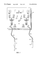
- FIG. 1 is a diagram of a microcurrent stimulation therapy apparatus having a microcurrent signal generator and a probe for applying the microcurrent to a body part;
- FIG. 2 is a block diagram of a circuit embodying the microcurrent signal generator of FIG. 1;
- FIG. 3 is a detailed circuit diagram of one embodiment of the microcurrent signal generator circuit of FIG. 2;
- FIG. 4 a illustrates eight therapy points around an eyelid to which microcurrent stimulation therapy may be applied in accordance with a method for treating visual system diseases
- FIG. 4 b illustrates eight therapy points on the back of the neck to which microcurrent stimulation therapy may be applied in accordance with a method for treating visual system diseases
- FIG. 4 c illustrates ten therapy points on the ear to which microcurrent stimulation therapy may be applied in accordance with a method for treating visual system diseases
- FIG. 4 d illustrates four therapy points on an arm to which microcurrent stimulation therapy may be applied in accordance with a method for treating visual system diseases
- FIG. 5 a illustrates a periodic sinusoidal wave signal having a set frequency which is a waveform signal generated by a prior art microcurrent generator
- FIG. 5 b illustrates the spectral or frequency response of the sinusoidal wave signal of FIG. 5 a
- FIG. 6 a illustrates a periodic square wave having a set frequency which is a waveform signal generated by a prior art microcurrent generator
- FIG. 6 b illustrates the spectral or frequency response of the square wave signal of FIG. 6 a
- FIG. 7 a is a swept sinusoidal waveform signal varying from about 0 Hz to about 125 Hz over a time frame in excess of 100 microseconds;
- FIG. 7 b is the spectral or frequency response of the waveform signal of FIG. 7 a;
- FIG. 8 a is a swept sinusoidal waveform varying from about 0 Hz to about 1.1 MHz over a time frame in excess of 1 microseconds;
- FIG. 8 b is the spectral or frequency response of the waveform signal of FIG. 8 a;
- FIG. 9 is an embodiment which allows digital control of the modulation frequency
- FIG. 10 is an embodiment which produces the output waveform using direct digital synthesis
- FIG. 11 is an embodiment of a triangular waveform
- FIG. 12 is an embodiment of a ramp waveform
- FIG. 13A is a first embodiment of bi-phasic pulses
- FIG. 13B is a second embodiment of bi-phasic pulses.
- the present invention comprises methods and apparatus for providing microcurrent simulation therapy for the treatment of chronic pain, visual system diseases and other bodily defects or diseases. More particularly, the present invention relates to a microcurrent waveform generator which generates sweep wave signals for use in microcurrent stimulation therapy. As discussed in more detail below, the microcurrent sweep wave generator disclosed herein may be used for any type of microcurrent stimulation therapy and will find its greatest use in treating patients suffering from macular degeneration.
- the present invention relates to a novel method for treating visual system diseases such as macular degeneration and retinitis pigmentosa using microcurrent stimulation therapy techniques.
- a novel microcurrent stimulation therapy apparatus 10 is shown in accordance with the present invention.
- Therapy apparatus 10 preferably comprises a sweep wave signal generator 12 , a stimulation probe 14 , and an electrode 16 .
- stimulation probe 14 is connected to sweep wave signal generator 12 via a first electrical connector 18
- electrode 16 is connected to sweep wave signal generator 12 via a second electrical connector 20 .
- a probe tip 22 preferably is connected to the end of stimulation probe 14 opposite the end of probe 14 connected to first electrical connector 18 .
- Stimulation probe 14 preferably comprises a shielded hand-held probe configured to administer microcurrent stimulation to various points on one or more body parts.
- probe tip 22 preferably comprises a cotton swab moistened or dampened with a conductive gel. The dampened cotton swab allows for the gentle administration of the microcurrent to the body part without undue discomfort.
- probe tip 22 may be made from a variety of different metals like copper, brass, aluminum, or the like, or probe tip 22 may be made from metal combinations or other conductive materials. In any event, any suitable probe tip may be used and, thus, the present invention is not limited to the illustrated embodiment.
- electrode 16 preferably comprises a handheld brass electrode.
- a closed circuit is created with stimulation probe 18 . That is, by holding electrode 16 , current from probe 18 will travel through the body, to brass electrode 16 and back to sweep wave signal generator 12 .
- electrode 16 may be a conductive clip device which attaches to a body part such as a finger, ear, arm or the like.
- first electrical connector 18 is configured to connect stimulation probe 14 to sweep wave signal generator 12
- second electrical connector 20 is configured to connect electrode 16 to sweep wave signal generator 12
- first and second electrical connectors 18 and 20 each preferably include a first connector end 24 for connection to generator 12 and a second connector end 26 for connection to stimulation probe 14 and electrode 16 , respectively.
- connectors 18 and 20 are removable from generator 12 and probe 14 and electrode 16 .
- connectors 18 and 20 may be hardwired to generator 12 , or to probe 14 and electrode 16 , or to both generator 12 and probe 14 and electrode 16 .
- electrical connectors 18 and 20 may comprise any suitable electrical connection device currently known in the art or hereinafter developed.
- sweep wave signal generator 12 preferably is configured to generate one or more sweep wave signals having various waveform, sweep frequency, sweep time, duty cycle, center frequency, frequency window, and amplitude characteristics.
- the generated sweep wave signal(s) are frequency varied signals. That is, the frequency of the signals vary over time.
- sweep wave signal generator 12 may produce a single sweep wave signal, or alternatively, sweep wave signal generator 12 may generate a composite signal comprising two independent swept wave signals or a swept wave signal and a non-swept wave signal.
- sweep wave signal generator 12 preferably comprises a first waveform control 32 and a second waveform control 34 .
- First waveform control 32 preferably controls the waveform type of a first sweep wave signal
- second waveform control 34 preferably controls the waveform type of a second sweep wave signal.
- First and second waveform controls 32 and 34 may be adjusted to produce a variety of different sweep waveforms.
- generator 12 will produce different waveforms, including sinusoidal waveforms, ramp waveforms, triangular waveforms, rectangular or square waveforms, step waveforms, window waveforms, unipolar waveforms, bipolar or bi-phasic waveforms or steady-state DC signals, to name a few.
- waveforms including sinusoidal waveforms, ramp waveforms, triangular waveforms, rectangular or square waveforms, step waveforms, window waveforms, unipolar waveforms, bipolar or bi-phasic waveforms or steady-state DC signals, to name a few.
- sweep wave signal generator 12 preferably is configured to control the range of frequencies between which the selected waveforms sweep, as well as the sweep time for performing the sweep of frequency ranges.
- generator 12 preferably has a first low frequency control 36 , a first high frequency control 38 , a first sweep time control 39 , a second low frequency control 40 , a second high frequency control 42 , and a second sweep time control 43 .
- First low frequency control 36 preferably controls the low frequency threshold for the first sweep wave signal
- first high frequency control 38 controls the high frequency threshold of the first sweep wave signal
- first sweep time control 39 controls the sweep time of the first sweep wave signal.
- second low frequency control 40 preferably controls the low frequency threshold of the second sweep wave signal
- second high frequency control 42 controls the high frequency threshold of the second sweep wave signal
- second sweep time control 43 controls the sweep time of the second sweep wave signal.
- the low frequency thresholds for both sweep wave signals may be in the range of about 0 Hz to about 400 Hz.
- the high frequency threshold for the two sweep wave signals may be in the range of about 0 Hz to about 2000 Hz.
- the sweep time for both the first and the second sweep wave signals preferably is in the range of about 7 seconds to about 60 seconds, and more preferably about 15 seconds. While the illustrated embodiment shows a low frequency control and a high frequency control for each sweep wave signal, one skilled in the art will appreciate that any frequency control scheme may be used.
- each sweep wave signal may have only one frequency control, or one low and one high frequency control may control both sweep wave signals. In any event, the present invention is not limited to the illustrated embodiment.
- sweep wave signal generator 12 preferably further comprises a voltage signal control 44 , a current control 46 , a first signal monitor port 50 , a second signal monitor port 52 , and a data-acquisition system port 54 .
- sweep wave signal generator 12 preferably further comprises a voltage limiting circuit and a current limiting circuit.
- voltage control 44 is configured to control the magnitude of the voltage signal peak or peak-to-peak output.
- current control 46 preferably is configured to control the current supplied to the body part of the patient by controlling the current limiting circuit.
- sweep wave signal generator 12 may be connected to one or more oscilloscopes, spectrum analyzers or waveform displays via first and second signal monitor ports 50 and 52 . By connecting generator 12 to one or more oscilloscopes, spectrum analyzers, or waveform displays, the waveform signal and current level at various locations within the generator circuit can be monitored.
- sweep wave signal generator 12 may further include a data-acquisition port 54 for connecting generator 12 to a data-acquisition system and/or a strip chart recorder.
- generator 12 preferably is configured to record various data, such as waveform, current and voltage levels, and the like for different patients, and then download the data to a data-acquisition system for monitoring and analysis.
- a doctor or practitioner can analyze data concerning variations in current levels between patients and different diseases of the visual system, as well as variations in the swept waveform for different patients and disease states. The doctor or practitioner can then use this data to track therapy progress, develop better therapy procedures for different patients, and monitor variabilities in treatment points. In addition, the doctor or practitioner can monitor probe contact consistency and patient progress for self-administered therapy patients. That is, for patients who use or administer the micro-current stimulation therapy to themselves, at home, the doctor or practitioner can use the collected data to determine whether the patient is administering the therapy correctly and whether the therapy protocol needs to be adjusted for that particular patient.
- sweep wave signal generator 12 may include both voltage control 44 and current control 46 , or generator 12 may be configured with only one of the two controls. For example, by controlling the magnitude of the voltage output signal for a given patient impedance, the current supplied to the patient is also controlled. Similarly, by controlling the current supplied to a patient having a given impedance, the voltage is also controlled. Thus, the present invention is not limited to the illustrated embodiment.
- the illustrated embodiment of sweep wave signal generator 12 shows a number of different control features, one skilled in the art will appreciate that certain control features may be eliminated and other control features may be added without departing from the spirit of the invention.
- sweep wave signal generator 12 may further comprise duty cycle controls for controlling the duty cycles of the first and second sweep wave signals.
- sweep wave signal generator 12 preferably further comprises a current level indicator 48 , a first frequency indicator 49 - 1 , and a second frequency indicator 49 - 2 .
- current level indicator 48 preferably displays the current being supplied to the patient.
- Current level indicator 48 may be configured to display root-mean-square (rms) or average current output for certain segments of treatment time.
- first and second frequency indicators 49 - 1 and 49 - 2 preferably are configured to display the frequency of the first and second sweep wave signals, respectively, as the signal sweeps through the frequency ranges.
- first and second frequency indicators 49 - 1 and 49 - 2 may be configured to display the frequency ranges between which the first and second sweep waves are to sweep.
- sweep wave signal generator circuit 55 preferably comprises a first sweep signal generator 60 , and a second sweep signal generator 62 .
- Both first and second sweep wave signal generators 60 , 62 preferably comprise a sweep control circuit 64 and a signal generator 66 .
- Sweep control circuit 64 preferably controls the sweep frequencies, sweep times and duty cycles of the signals, and signal generator 66 preferably generates a particular waveform having the sweep frequencies, sweep times and duty cycles dictated by control circuit 64 .
- First and second sweep wave signal generators 60 and 62 may be configured to generate swept waves, or non-swept waves. For example, by setting the high and low sweep frequencies to the same frequency for a particular signal, the signal generator will generate a signal having a set frequency.
- first and second sweep signal generators 60 and 62 may comprise any suitable sweep signal generator currently known in the art.
- function generator with sweep control product no. PM5132, manufactured by Philips Corporation, may be used.
- sweep signal generator 60 and 62 may be configured to generate a wide variety of waveforms having a variable range of sweep frequencies and sweep times.
- first sweep signal generator 60 preferably generates a first sweep wave signal 68 and second sweep signal generator 62 preferably generates a second sweep wave signal 70 .
- a signal combiner/adder circuit 72 preferably receives first sweep wave signal 68 and second sweep wave signal 70 and combines the two signals into a single sweep wave signal 74 . From combiner/adder circuit 72 , sweep wave signal 74 preferable passes to a buffer/amplifier circuit 76 , which is configured to amplify and buffer single sweep wave 74 , generating a buffered sweep wave signal 78 .
- buffered sweep wave signal 78 preferably passes into a voltage clipping or limiting circuit 80 , which is configured to control the polarity of the output voltage to a predetermined voltage level and polarity.
- the output of clipping or limiting circuit 80 is a clipped voltage signal 82 which preferably passes to a current limiting circuit 84 configured to limit the total current output supplied to a particular body part.
- a current level indicator 86 Connected to current limiting, circuit 84 is a current level indicator 86 , which preferably is a volt meter configured to monitor and display the output current level.
- sweep wave signal generator 12 preferably comprises a voltage control 44 and a current control 46 .
- voltage control 44 preferably is configured to control the voltage signal peak or peak-to-peak output from voltage clipping or limiting circuit 80 .
- voltage clipping or limiting circuit 80 is adjusted so that the amplitude of the output voltage changes as necessary.
- current control 46 of signal generator 12 preferably is configured to control the current output from current limiting circuit 84 .
- Current level indicator 86 may comprise any suitable current measuring and displaying device. As discussed in more detail below with reference to FIG. 3, current level indicator 86 may comprise, for example, a voltage measuring device configured across current limiting circuit 84 . As one skilled in the art will appreciate, the amount of current flowing through current limiting circuit 84 is a function of the voltage across the circuit, as well as the resistance of the circuit itself. Once the current level is determined, current level indicator 86 preferably displays the current level on current level display 48 of signal generator 12 (see FIG. 1 ). Current level indicator 86 can be configured to measure the root-mean-square (RMS) current, or indicator 86 may be configured to measure an average current over a particular time period.
- RMS root-mean-square
- signal generator circuit 55 may be configured without voltage clipping or limiting circuit 80 .
- amplified sweep wave signal 78 passes directly to current limiting circuit 84 .
- This particular embodiment of the invention is illustrated in FIG. 2 as dotted line 78 passing into circuit 88 comprising current limiting circuit 84 and current level indicator 86 .
- current limiting circuit 84 and current level indicator 86 preferably operate in the same general manner as that described above with reference to the first embodiment. Accordingly, a detailed discussion of circuit 88 will not be discussed further.
- sweep wave signal generating circuit 55 may further comprise connections 90 and 92 for connection to one or more oscilloscopes, spectrum analyzers or waveform displays. As illustrated in FIG. 2, in accordance with a preferred embodiment of the present invention, signal generating circuit 55 preferably has two connections, one prior to voltage clipping or limiting circuit 80 and one after voltage clipping or limiting circuit 80 .
- an oscilloscope, spectrum analyzer, or waveform display connected to connection 90 will display the waveform of the sweep wave signal from buffer/amplifier circuit 76
- the second oscilloscope, spectrum analyzer, or waveform display connected to connection 92 will display the sweep wave signal after it has passed through voltage clipping or limiting circuit 80 . Accordingly, the operator of the device can be sure that voltage clipping or limiting circuit is functioning properly by analyzing the signals entering and leaving the circuit. In the embodiment in which the voltage clipping or limiting circuit is eliminated, only one connection to an oscilloscope or spectrum analyzer is present.
- the sweep wave signal generator circuit 55 may further comprise a data acquisition module 94 for collecting data about the performance of the therapy device, and in particular, generator circuit 55 .
- data acquisition module 94 preferably is connected so that it can monitor first and second sweep waves 68 and 70 , buffered sweep wave signal 78 , clipped voltage signal 82 , and the current and voltage of the output signals.
- the collected data can then be downloaded to data acquisition system for analysis by a doctor or therapist.
- the data acquisition system may comprise any suitable data acquisition system, such as a computer system configured to manipulate and display such data.
- signal generating circuit 55 preferably comprises a first sweep wave signal generator 60 , a second sweep wave signal generator 62 , a signal combiner or adder circuit 72 a buffer/amplifier circuit 76 , a voltage limiting or clipping circuit 80 , a current limiting circuit 84 and a current level monitor/indicator 86 .
- signal adder or combiner circuit 72 and buffer/amplifier circuit 76 preferably are combined into a single operational amplifier circuit 100 .
- Op amp circuit 100 preferably receives a first sweep wave signal 102 from first sweep wave signal generator 60 and a second sweep wave signal 104 from second sweep wave signal generator 62 .
- first sweep wave signal 102 is connected to negative input terminal 112 of an op amp 110 through a first resistor 106
- second sweep wave signal 104 is connected to negative input terminal 112 of op amp 110 through a second resistor 108 .
- First resistor 106 and second resistor 108 preferably are in the range of about 1 kiloohm to about 25 kiloohms, and more preferably are about 10 kiloohms.
- Op amp 110 further comprises a positive input terminal 114 which preferably is connected to ground, and an output terminal 116 which preferably is connected in a negative feedback loop to negative input terminal 112 through a variable resistor 118 .
- variable resistor 118 may have a variable resistance which ranges between about 1 to about 50 kiloohms, and more preferably ranges between about 3.3 to about 7.8 kiloohms.
- While one embodiment of the present invention disclosed herein utilizes an op amp as a signal adder and buffer amplifier, one skilled in the art will appreciate that other circuit configurations may be used to accomplish the amplifier, adder, and buffering tasks. Thus, the present invention is not limited to an embodiment comprising an op amp circuit.
- voltage clipping or limiting circuit 80 preferably comprises a diode 22 and a variable resistor 124 .
- Variable resistor 124 is connected between a first terminal of diode 122 and ground. With this particular configuration, the adjustment of variable resistor 124 preferably adjusts the limit of the voltage amplitude output.
- variable resistor 124 preferably has a resistance which ranges between about 5 to about 50 kiloohms, and more preferably between about 15 to about 25 kiloohms.
- voltage clipping or limiting circuit 80 comprising a resistor/diode combination
- any voltage limiting circuit configuration may be used.
- voltage clipping or limiting circuit 80 may comprise an operational amplifier configured as a limiting circuit. Therefore, the present invention is not limited to the illustrated embodiment.
- a clipped wave signal 126 preferably passes into current limiting circuit 84 .
- current limiting circuit 84 comprises a resistor 128 .
- resistor 128 preferably has a value between about 10 and about 500 kiloohms, and more preferably a value between about 20 kiloohms and about 115 kiloohms.
- resistor 128 As a constant resistance value
- current limiting circuit 84 is shown as a resistor, any suitable current limiting circuit configuration may be used.
- a circuit comprising transistors, resistors, diodes, and the like may be used instead of a simple resistor.
- current level monitor/indicator 86 is configured to measure the current output from current limiting circuit 84 .
- current level monitor/indicator 86 preferably comprises a device which is configured to measure the voltage across resistor 128 , which in turn will give the current flowing through the resistor.
- circuit 55 may further comprise a data acquisition module for collecting therapy and waveform data.
- the fundamental difference between the swept and the non-swept waveform is the continuous nature of the spectral characteristics and the time-frequency variation with analog waveforms, and the almost continuous nature (i.e., somewhat discrete) for the spectral characteristics of a swept digital or pulsed waveform.
- the human body behaves like a dispersive filter and a waveform that is swept in the appropriate manner may be preferred for electro-therapy.
- the swept waveform is more likely to provide the optimal frequency which maximizes the therapeutic value for large numbers of people afflicted with various types of visual system diseases.
- FIGS. 5 a , 5 b , 6 a , 6 b , 7 a , 7 b , 8 a , and 8 b fundamental differences between discreet frequency wave signals and sweep wave signals is illustrated.
- FIG. 5 a illustrates a 2 volt (peak-to-peak) sinusoidal waveform having a set frequency of about 3 MHz.
- This type of waveform is a typical analog waveform generated by microcurrent stimulation devices currently known in the art.
- the spectral or frequency components of the sinusoidal waveform appear at only one discreet frequency. With this type of signal, all of the power from the signal is located at or near the 3 MHz frequency.
- FIG. 6 a illustrates a 3.2 volt (peak-to-peak) rectangular waveform having a peak overshoot and a frequency of about 6 MHz.
- this waveform type is a typical digital or pulsed waveform produced by microcurrent stimulation devices currently known in the art.
- the rectangular waveform has a fundamental frequency component at 6 MHz and diminishing harmonics at 18, 30 and 42 MHz, respectively. With this type of signal, approximately 80% of the power is associated with the fundamental frequency of 6 MHz.
- FIG. 7 a a 10 volt (peak-to-peak) swept sinusoidal waveform varying from about 0 Hz to about 125 Hz over a time frame of more than 100 microseconds is shown.
- the frequency of the waveform changes with time.
- FIG. 7 b shows the frequency or spectral characteristics of the waveform of FIG. 7 a .
- the frequency or spectral characteristics of the swept analog waveform are continuous, not discreet, like they are with the fixed frequency signal of FIGS. 5 b .
- the power is not concentrated at one or a few frequencies, but is spread over the entire frequency range.
- the power at any discreet frequency in the spectrum is 0 watts.
- FIG. 8 a illustrates a 10 volt (peak-to-peak) swept sinusoidal waveform varying from 0 Hz to 1.1 MHz over a time frame of more than 100 microseconds is shown.
- the frequency or spectral characteristics of the swept analog waveform is continuous over the wide frequency range and, thus, the power is spread out over all frequencies.
- waveform characteristics are preferable for microcurrent stimulation therapy, and in particular, macular degeneration therapy.
- a method for treating visual system diseases and in particular, a method for treating macular degeneration will be described.
- a microcurrent stimulation therapy device using a swept digital or pulsed signal, similar to the embodiments described above, is used.
- a brass cylinder or rod preferably is held in one hand of the patient, and a brass microcurrent stimulation probe with a shielded handle is applied to the patient by the therapist.
- the brass cylinder or rod conducts the electric current allowing the current to pass through the particular body part for therapy.
- each eye that shows signs of macular degeneration is treated by providing a microcurrent through four points on the upper and four points on the lower eyelid for a total of eight points around the eye.
- FIG. 4 a illustrates the eight points around the eye which are stimulated and the preferred order of stimulation.
- the stimulation preferably occurs in the order from point one to point eight.
- the patient preferably looks away from the probe with eyes closed. This rolls the macula closer to the stimulation point, keeping the microcurrent from passing through dense eye structures, such as lens, iris and ciliany body, resulting in better microcurrent penetration into the macula region.
- the eight points around the eye are stimulated using a current between about 50 to about 350 microamps, and more preferably between about 150 and 250 microamps.
- the current applied to the eyelid is brought up until the patient sees light flashes and/or feels the tinge of electricity. The current is then decreased so that the patient feels no discomfort. This is the preferred current level used for the therapy.
- each point around the eye is stimulated for about 8 to about 60 seconds, and more preferably for about 30 seconds, using a sweep wave signal.
- the sweep wave signal may comprise one swept signal, or two independent sweep wave signals combined by an adder/buffer circuit.
- one of the sweep wave signals preferably comprises a rectangular sweep wave signal having a peak-to-peak voltage of between about 10 to about 30 volts, and more preferably about 20 volts.
- the square or rectangular sweep wave signal preferably has a sweep wave frequency range of about 0 to about 400 Hz, and more preferably of about 0 to about 35 Hz; has a sweep time of between about 7 and about 60 seconds, and more preferably of about 15 seconds; and has a duty cycle of between about 20 and about 95 percent, and more preferably of about 75 percent.
- the other signal generator preferably provides a sweep wave signal having a lower peak-to-peak voltage than the first sweep wave signal.
- the second sweep wave signal preferably has a peak-to-peak voltage of between about 0.1 to about 4 volts and more preferably about 1 volt, if needed.
- the second sweep wave signal preferably has a sweep wave frequency range of about 500 to about 2 MHz, and more preferably of about 500 to about 1.5 MHz; and a sweep time of between about 7 and about 60 seconds, and more preferably of about 15 seconds.
- the second sweep wave signal may comprise a sinusoidal waveform, a square waveform, a triangular waveform, a ramp waveform, a step waveform, or the like.
- the second signal comprises a non-swept or fixed frequency signal, rather than a swept or sweep wave signal.
- the non-swept wave signal may comprise a sinusoidal wave, a square or rectangular wave, a ramp wave, a step wave, or the like.
- the non-swept wave signal has a peak or peak-to-peak voltage of between about 0.1 to about 4 volts, and more preferably about 1 volt.
- the fixed frequency of the non-swept wave signal preferably is in the range of about 500 Hz to 2 MHz, and more preferably in the range of about 500 Hz to 1.5 MHz.
- the method for treating macular degeneration may include treating other acupuncture or pressure points on the body.
- FIG. 4 a there are 2 points, A and B, on the forehead which can be used for microcurrent stimulation.
- two probes preferably are attached to the frontal area of the forehead at points A and B, and a microcurrcnt scan is applied to these points for about 10 to 20 minutes, and more preferably for about 15 minutes. In this manner, a relaxation mode of the therapy procedure is applied to the patient.
- the conductance of electricity in the head area is increased, thus helping relax the patient, as well as providing other therapeutic affects.
- some of the microcurrent is scattered toward the eye region, thus supplying additional microcurrent therapy to the eyes.
- FIG. 4 b there are eight acupuncture or pressure points on the back of the neck which may be stimulated during macular degeneration therapy.
- each pressure point 1 - 8 is stimulated in ascending order for about 20 to about 60 seconds.
- FIG. 4 c shows 10 acupuncture or pressure points on the ear which also may be stimulated for macular degeneration therapy.
- each point 1 - 10 on the ear is stimulated in ascending order for about 10 to about 30 seconds.
- FIG. 4 d illustrates four pressure points on an arm which also may be stimulated in the same manner as with the eyes, neck and ears.
- similar waveforms are used on the eyes, neck, ears and arms.
- different waveforms may be used on the different body parts, depending on the therapeutic effect of a particular waveform at a particular location.
- patients initially are treated twice a day for 4 days and 3 times a week thereafter.
- This embodiment includes a controller 200 , a read only memory (ROM) 204 , a digital-to-analog converter (DAC) 208 , a voltage controlled oscillator (VCO) 212 , a voltage limiter circuit 214 , a current level indicator 216 , a data acquisition module 224 , and a current sensor and limiter circuit 228 .
- ROM read only memory
- DAC digital-to-analog converter
- VCO voltage controlled oscillator
- VCO voltage controlled oscillator
- the controller 200 reads values from a lookup table in the ROM 204 to produce a digital word for the DAC 208 .
- the DAC 208 converts a digital word into an analog voltage which is then coupled to the VCO 212 .
- the analog voltage frequency modulates the oscillation of the VCO 212 to produce a modulated frequency.
- the modulated output from the VCO 212 passes through the voltage limiter circuit 214 .
- the voltage control may be provided by a potentiometer, or other known method.
- a current sensor and limiter circuit 228 Monitoring and regulating of the current applied to the patient is performed with a current sensor and limiter circuit 228 .
- the current sensor and limiter circuit 228 regulates the signal to a level selected by the user by using a potentiometer, or the like which is coupled to the current control input. Additionally, the current sensor and limiter circuit 228 passes the signal through a resister so that the current can be sensed as it varies the voltage drop across the resister. To allow application to a patient, the output from the current sensor and limiter circuit 228 is coupled to a probe tip. In this way, the controller can digitally modulate a signal frequency applied to the patient.
- the current level indicator 216 displays the current level sensed from the signal and feeds this information to the data acquisition module 224 .
- the indicator 216 can have both visual and audio outputs. For example, it may be a series of LEDs which light up in succession according to the current level. Furthermore, the current level indicator 216 can utilize digital and analog techniques to show the patient the present current applied.
- the current measured by the current level indicator 216 is passed to the data acquisition module 224 . Additionally, the data acquisition module 224 can record the applied voltage over time so that both current and voltage is known. The physician can download the information from the data acquisition module 224 to analyze the output signal applied to the patient. In other embodiments, the current information could be fed back to the controller such that closed loop feedback could more precisely adjust the output current.
- the lookup table within the ROM 204 can store any number of frequency sequences. Additionally, the controller can repeat the entries of the lookup table in a loop to conserve room. Each digital word read from the ROM 204 corresponds to an analog voltage. The analog voltage is applied to the VCO 212 to produce a predetermined modulation frequency.
- the ROM 204 is preferably a non-volatile and reprogrammable memory device such as an EPROM, an EEPROM, a FLASH memory, or the like. Depending upon the treatment regiment specified, the lookup table within the ROM can be modified by the patient's physician. In this way, any number of frequency sequences can be produced by the therapy apparatus 232 .
- the digital modulation of the microcurrent stimulation therapy apparatus 232 can provide precision in controlling the spectral response of the signal applied to the patient. Over time, the spectral response exhibits specific frequency components which corresponded to the various frequencies produced by the VCO 212 . As described above, the frequency produced by the VCO 212 is achieved from a digital data word stored in a lookup table in the ROM 204 . In a non-linear manner, the frequency components from the lookup table could be distributed over the spectrum. The lookup table could sweep the frequency through the spectrum or achieve any different frequency at any time. Therapies for different types of medical conditions my require a more complex spectral response than merely sweeping the frequency from one end of the spectrum to the other.
- the digital frequency modulation technique could, for example, sweep from 2 KHz through 4 KHz and then sweep from 7 KHz to 9 KHz.
- the controller 200 could repeat the delivery of digital data words in a loop to continually repeat the frequency modulation sequence.
- the wide variety of possible spectral responses allows the therapy apparatus 232 to provide a response that is useful in the treatment of many different health problems such as diseases of the visual system (including macular degeneration and retinitis pigmentosa), orthopedic problems (including sciatica), pain and fatigue disorders (including myofascial pain syndrome, fibromyalgia, sciatica, and neuralgia), and perhaps certain types of cancer (including retinoblastoma cells).
- the microcurrent stimulation therapy apparatus 232 can achieve small electronically controlled frequency variations where the change in frequency over time is automatic. This provides the capability to treat a patient with a wider range of frequencies and frequency combinations.
- the waveforms could be unipolar, bipolar or bi-phasic. Unipolar waveforms are characterized by being always positive or always negative; bipolar waveforms are characterized by being both positive and negative, but not necessarily symmetric about the zero potential axis; and bi-phasic waveforms are characterized by being symmetric about the zero potential axis.
- This embodiment utilizes frequency modulation (FM), to provide a frequency swept output waveform which distributes the specific frequency components over time.
- FM frequency modulation
- Other embodiments with analog swept sinusoidal output signals which distribute the frequency over time produce a continuous spectral density function.
- the spectral density function will also exhibit specific frequency components distributed over time. Accordingly, the spectral density function may also exhibit discrete properties.
- Digital frequency sweep techniques include (but are not limited to) voltage/current control of an oscillator, programmable frequency division of a oscillating signal and table look-up of the frequency. For example, a programmable number of flip flops could divide a source frequency into any number of lower frequencies.
- the change in frequency of this embodiment over time is automatic, providing the capability to treat the patient with a wider range of frequencies and frequency combinations.
- a microcurrent stimulation therapy apparatus 332 which directly synthesizes the output waveform without using the above described digital modulation technique, is shown in block diagram form.
- Direct synthesis is the process by which a waveform is recreated by a controller 200 using values from a ROM 204 to control a signal source 336 .
- a VCO would not be required and the signal source 208 feeds directly to the current sensor and limiter 228 .
- the ROM 204 contains a look-up table providing an output to the controller 200 that controls the voltage level of the output signal from the signal source 208 .
- the digital words are reformatted, if necessary, and coupled to the signal source 336 .
- the signal source 208 creates a voltage which corresponds to the digital word.
- the signal source 208 functions as a digital to analog converter in this embodiment.
- the waveform output from the signal source 208 is comprised of constituent voltage levels which over time create a signal of a single frequency or multiple frequencies. Each constituent voltage corresponds to a digital word from the ROM 204 .
- the signal could have any number of predetermined shapes. As can be appreciated by those skilled in the art, use direct digital synthesis allows producing complex waveforms with many constituent frequency components.
- the controller 200 could feed the period of the waveform in a continuous loop to recreate the periodic nature of the waveform.
- a simple example of this is a period which is comprised of a data word of all zeros and a data word of all ones.
- the data words When fed to the DAC 208 in a loop, the data words would create an oscillating square wave with a period of twice the sampling period of the signal source 336 . In this way, waveforms of any shape can be directly digitally synthesized.
- the controller 200 reads a value from the ROM 204 to produce a voltage.
- the voltage is coupled to the signal source 336 where the voltage is used to select a oscillation frequency. As the voltage varies, so does the oscillation frequency, such that a range of frequencies is possible as proscribed by the ROM 204 .
- the signal source 336 performs as a voltage controlled oscillator where the voltage which corresponds to the digital word selects the output frequency.
- a current could also be used to control the signal source 336 .
- the controller 200 reads a value from the ROM 204 which corresponds to a pulse.
- the pulse is created by the controller 200 and fed to the signal source 336 .
- the signal source uses the pulse to select a frequency to generate. By varying the pulse, any number of frequencies are selected.
- FIGS. 11 and 12 embodiments of a triangular waveform and a ramp waveform are respectively shown. Voltage is shown in the ordinate direction and time is shown along the abscissa.
- FIGS. 13A and 13B embodiments of bi-phasic pulses are shown. More specifically, FIG. 13A shows a bipolar return-to-zero pulse waveform, and FIG. 13B shows a Manchester code pulse waveform. Voltage is shown in the ordinate direction and time is shown along the abscissa. Bi-phasic pulse waveforms have pulses that have a positive and negative polarity and arc not necessarily symmetrical with respect to positive and negative polarity.
- the present invention provides novel methods and apparatus for using microcurrent stimulation therapy to treat various physiological problems, such as pain, wounds and visual eye diseases.
- various physiological problems such as pain, wounds and visual eye diseases.
- various circuit configurations may be used; such as, digital signal processing circuits or digitally generated wave signal circuits.
- one preferred method for treating macular degeneration is disclosed, other suitable methods may be used to treat macular degeneration, other eye diseases or other chronic problems such as pain and persistent sores.
- any number of sweep signal generator circuits and therapy methods may be used without varying from the spirit of the invention. Therefore, the above description should not be taken as limiting the scope of the invention which is defined by the appended claims.
Abstract
Description
Claims (23)
Priority Applications (6)
| Application Number | Priority Date | Filing Date | Title |
|---|---|---|---|
| US09/346,772 US6275735B1 (en) | 1998-07-13 | 1999-07-07 | Methods and apparatus for electrical microcurrent stimulation therapy |
| AU49853/99A AU4985399A (en) | 1998-07-13 | 1999-07-12 | Methods and apparatus for electrical micro-current stimulation therapy |
| PCT/US1999/015685 WO2000002622A1 (en) | 1998-07-13 | 1999-07-12 | Methods and apparatus for electrical micro-current stimulation therapy |
| EP08014436A EP1985332A1 (en) | 1998-07-13 | 1999-07-12 | Apparatus for electrical microcurrent stimulation therapy |
| EP99933899A EP1096970A4 (en) | 1998-07-13 | 1999-07-12 | Methods and apparatus for electrical micro-current stimulation therapy |
| CA002337214A CA2337214A1 (en) | 1998-07-13 | 1999-07-12 | Methods and apparatus for electrical micro-current stimulation therapy |
Applications Claiming Priority (2)
| Application Number | Priority Date | Filing Date | Title |
|---|---|---|---|
| US09/114,815 US6035236A (en) | 1998-07-13 | 1998-07-13 | Methods and apparatus for electrical microcurrent stimulation therapy |
| US09/346,772 US6275735B1 (en) | 1998-07-13 | 1999-07-07 | Methods and apparatus for electrical microcurrent stimulation therapy |
Related Parent Applications (1)
| Application Number | Title | Priority Date | Filing Date |
|---|---|---|---|
| US09/114,815 Continuation-In-Part US6035236A (en) | 1998-07-13 | 1998-07-13 | Methods and apparatus for electrical microcurrent stimulation therapy |
Publications (1)
| Publication Number | Publication Date |
|---|---|
| US6275735B1 true US6275735B1 (en) | 2001-08-14 |
Family
ID=22357596
Family Applications (2)
| Application Number | Title | Priority Date | Filing Date |
|---|---|---|---|
| US09/114,815 Expired - Lifetime US6035236A (en) | 1998-07-13 | 1998-07-13 | Methods and apparatus for electrical microcurrent stimulation therapy |
| US09/346,772 Expired - Lifetime US6275735B1 (en) | 1998-07-13 | 1999-07-07 | Methods and apparatus for electrical microcurrent stimulation therapy |
Family Applications Before (1)
| Application Number | Title | Priority Date | Filing Date |
|---|---|---|---|
| US09/114,815 Expired - Lifetime US6035236A (en) | 1998-07-13 | 1998-07-13 | Methods and apparatus for electrical microcurrent stimulation therapy |
Country Status (2)
| Country | Link |
|---|---|
| US (2) | US6035236A (en) |
| EP (1) | EP1985332A1 (en) |
Cited By (73)
| Publication number | Priority date | Publication date | Assignee | Title |
|---|---|---|---|---|
| US20030074030A1 (en) * | 2001-09-28 | 2003-04-17 | Vertis Neuroscience, Inc. | Method and apparatus for controlling percutaneous electrical signals |
| US20030233137A1 (en) * | 2002-06-13 | 2003-12-18 | Paul Edward L. | Transcutaneous electrical nerve stimulation device and method using microcurrent |
| US20030233135A1 (en) * | 2002-06-14 | 2003-12-18 | Yee Richard W. | Method and apparatus for preventing and treating eyelid problems |
| US20040176820A1 (en) * | 2002-06-13 | 2004-09-09 | Paul Edward L. | Method and apparatus for performing microcurrent stimulation (MSC) therapy |
| US20050004625A1 (en) * | 2001-06-29 | 2005-01-06 | Chow Alan Y. | Treatment of degenerative retinal disease via electrical stimulation of surface structures |
| US20050033202A1 (en) * | 2001-06-29 | 2005-02-10 | Chow Alan Y. | Mechanically activated objects for treatment of degenerative retinal disease |
| WO2005023362A1 (en) * | 2003-09-09 | 2005-03-17 | R.I.S.E. Ltd | Electrostimulation device and method |
| US20050137649A1 (en) * | 2002-06-13 | 2005-06-23 | Paul Edward L.Jr. | Method and apparatus for performing microcurrent stimulation (MSC) therapy |
| WO2005061049A1 (en) | 2003-12-15 | 2005-07-07 | Atlantic Medical, Inc. | Method and apparatus for performing microcurrent stimulation (msc) therapy |
| WO2005068018A1 (en) * | 2003-12-17 | 2005-07-28 | Atlantic Medical, Inc. | Method and apparatus for performing microcurrent stimulation (msc) therapy |
| US20050209656A1 (en) * | 2004-03-19 | 2005-09-22 | Chen George C C | Method and apparatus for applying microcurrent to eyes |
| US20050267548A1 (en) * | 2004-05-28 | 2005-12-01 | Yu Eukki Q | Device for enhancing cell metabolism |
| US20060142818A1 (en) * | 2001-06-29 | 2006-06-29 | Optobionics | Methods for improving damaged retinal cell function |
| US20060178660A1 (en) * | 2005-02-08 | 2006-08-10 | Ns Welltec Gmbh | System for the stimulation of acupuncture points |
| US20060217783A1 (en) * | 2004-02-06 | 2006-09-28 | Harold Thomas W | Treatment of vision disorders using electrical, light, and/or sound energy |
| US20070016254A1 (en) * | 2005-07-18 | 2007-01-18 | Grenon Stephen M | Method and apparatus for treating gland dysfunction employing heated medium |
| US20070060988A1 (en) * | 2005-07-18 | 2007-03-15 | Grenon Stephen M | Melting meibomian gland obstructions |
| US7228180B1 (en) | 2003-10-09 | 2007-06-05 | Stroke Play Ltd. | Methods for treating victims of cerebrovascular disease |
| US20080046048A1 (en) * | 2006-05-15 | 2008-02-21 | Grenon Stephen M | Treatment of obstructive disorders of the eye or eyelid |
| US20080046053A1 (en) * | 2006-06-19 | 2008-02-21 | Wagner Timothy A | Apparatus and method for stimulation of biological tissue |
| USRE40279E1 (en) | 1997-06-26 | 2008-04-29 | Sherwood Services Ag | Method and system for neural tissue modification |
| US20080114424A1 (en) * | 2006-05-15 | 2008-05-15 | Grenon Stephen M | System for inner eyelid treatment of meibomian gland dysfunction |
| US20080114423A1 (en) * | 2006-05-15 | 2008-05-15 | Grenon Stephen M | Apparatus for inner eyelid treatment of meibomian gland dysfunction |
| WO2009058258A1 (en) * | 2007-10-29 | 2009-05-07 | Case Western Reserve University | Onset-mitigating high-frequency nerve block |
| USRE41045E1 (en) | 1996-06-27 | 2009-12-15 | Covidien Ag | Method and apparatus for altering neural tissue function |
| US20100070006A1 (en) * | 2006-06-19 | 2010-03-18 | Wagner Timothy Andrew | Interface apparatus for stimulation of biological tissue |
| US20110022010A1 (en) * | 2005-07-18 | 2011-01-27 | Tearscience, Inc. | Method and apparatus for treating meibomian gland dysfunction employing fluid jet |
| DE202010001150U1 (en) | 2010-01-15 | 2011-05-26 | Okuvision GmbH, 72770 | Device for electrostimulation |
| WO2011086150A2 (en) | 2010-01-15 | 2011-07-21 | Okuvision Gmbh | Electrostimulation device |
| WO2011118919A2 (en) * | 2010-03-26 | 2011-09-29 | Lee Ji Hun | Microcurrent generation device |
| US20120316620A1 (en) * | 2009-10-12 | 2012-12-13 | Newsouth Innovations Pty Limited | Method of power and data transfer in implantable electronic devices |
| WO2013037618A1 (en) | 2011-09-12 | 2013-03-21 | Okuvision Gmbh | System for treating an eye |
| US8491508B2 (en) | 2010-09-15 | 2013-07-23 | Walton F. Smith | Device and method for stimulating the meibomian glands of the eyelid |
| US8523928B2 (en) | 2006-05-15 | 2013-09-03 | Tearscience, Inc. | System for inner eyelid heat and pressure treatment for treating meibomian gland dysfunction |
| US8617229B2 (en) | 2006-05-15 | 2013-12-31 | Tearscience, Inc. | System for outer eyelid heat and pressure treatment for treating meibomian gland dysfunction |
| US8632578B2 (en) | 2006-05-15 | 2014-01-21 | Tearscience, Inc. | System for providing heat treatment and heat loss reduction for treating meibomian gland dysfunction |
| US8731657B1 (en) | 2011-07-05 | 2014-05-20 | TAMA Research Corp. | Multi-mode microcurrent stimulus system with safety circuitry and related methods |
| US8892200B2 (en) | 2006-06-19 | 2014-11-18 | Highland Instruments, Inc. | Systems and methods for stimulating tissue using focused energy |
| US9050463B2 (en) | 2011-08-24 | 2015-06-09 | Highland Instruments, Inc. | Systems and methods for stimulating cellular function in tissue |
| US9162060B2 (en) | 2009-03-20 | 2015-10-20 | Retina Implant Ag | Active retinal implant |
| US9216028B2 (en) | 2005-07-18 | 2015-12-22 | Tearscience, Inc. | Apparatuses for treatment of meibomian glands |
| US9220894B1 (en) * | 2014-08-13 | 2015-12-29 | TrioWave Technologies | Overshoot waveform in micro current therapy |
| USD759803S1 (en) | 2014-10-28 | 2016-06-21 | Highland Instruments, Inc. | Adjustable headpiece with anatomical markers |
| WO2017048731A1 (en) * | 2015-09-15 | 2017-03-23 | Amerivision International, Inc. | Apparatus and method for ocular microcurrent stimulation therapy |
| US9669227B2 (en) | 2015-06-09 | 2017-06-06 | Nuvectra Corporation | Systems, methods, and devices for generating arbitrary stimulation waveforms |
| US9681820B2 (en) | 2010-10-21 | 2017-06-20 | Highland Instruments, Inc. | Systems for detecting a condition |
| US9719977B2 (en) | 2005-07-18 | 2017-08-01 | Tearscience, Inc. | Methods and systems for treating meibomian gland dysfunction using radio-frequency energy |
| US9750946B2 (en) | 2015-06-09 | 2017-09-05 | Nuvectra Corporation | Systems, methods, and devices for evaluating lead placement based on generated visual representations of sacrum and lead |
| US20170266446A1 (en) * | 2016-03-16 | 2017-09-21 | Nova Oculus Partners, Llc | Microcurrent device and method for the treatment of visual disease |
| US9872988B2 (en) | 2015-06-09 | 2018-01-23 | Nuvectra Corporation | Systems, methods, and devices for evaluating lead placement based on patient physiological responses |
| US9889296B2 (en) | 2014-08-29 | 2018-02-13 | Triowave Technologies, Inc. | Signal adjustment for electrotherapy |
| US9913678B2 (en) | 2005-07-18 | 2018-03-13 | Tearscience, Inc. | Methods, apparatuses, and systems for reducing intraocular pressure as a means of preventing or treating open-angle glaucoma |
| US9913976B2 (en) | 2006-06-19 | 2018-03-13 | Highland Instruments, Inc. | Systems and methods for stimulating and monitoring biological tissue |
| US10052490B2 (en) | 2015-06-09 | 2018-08-21 | Nuvectra Corporation | Systems, methods, and devices for performing electronically controlled test stimulation |
| US10076667B2 (en) | 2015-06-09 | 2018-09-18 | Nuvectra Corporation | System and method of performing computer assisted stimulation programming (CASP) with a non-zero starting value customized to a patient |
| EP3524318A1 (en) * | 2018-02-13 | 2019-08-14 | Hoi Ming Michael Ho | Electrotherapy device capable of gradually increasing stimulation intensity |
| US10456579B2 (en) | 2017-05-02 | 2019-10-29 | Nova Oculus Canada Manufacturing Ulc | Direct electrical stimulation delivery system for the treatment of visual disease |
| US10668292B2 (en) | 2018-03-22 | 2020-06-02 | Pacesetter, Inc. | Implantable medical devices, and methods of use therewith, that detect MRI systems with enhanced specificity |
| WO2020131329A1 (en) | 2018-12-20 | 2020-06-25 | I-Lumen Scientific, Inc. | Apparatus and method for microcurrent stimulation therapy |
| US10842670B2 (en) | 2012-08-22 | 2020-11-24 | Johnson & Johnson Vision Care, Inc. | Apparatuses and methods for diagnosing and/or treating lipid transport deficiency in ocular tear films, and related components and devices |
| US11116973B1 (en) | 2020-10-09 | 2021-09-14 | I-Lumen Scientific, Inc. | System and method for a medical device |
| US11116965B2 (en) | 2017-12-13 | 2021-09-14 | Neuros Medical, Inc. | Nerve cuff deployment devices |
| US11213682B2 (en) | 2018-04-09 | 2022-01-04 | Neuros Medical, Inc. | Apparatuses and methods for setting an electrical dose |
| US11305118B2 (en) | 2018-11-30 | 2022-04-19 | Biovisics Medical, Inc. | Head worn apparatuses for vision therapy |
| US11338139B2 (en) | 2018-10-01 | 2022-05-24 | Biovisics Medical, Inc. | System and methods for controlled electrical modulation for vision therapy |
| US11413458B2 (en) | 2011-05-19 | 2022-08-16 | Neuros Medical, Inc. | Nerve cuff electrode for neuromodulation in large human nerve trunks |
| EP3877037A4 (en) * | 2018-11-08 | 2022-08-24 | Checkpoint Surgical, Inc. | Nerve regeneration therapy system and method |
| US11471680B2 (en) | 2019-04-10 | 2022-10-18 | Biovisics, Inc. | Systems and interfaces for ocular therapy |
| EP4091660A1 (en) | 2021-05-20 | 2022-11-23 | Subvision S.r.l. | Electrostimulator for vision |
| US11511112B2 (en) | 2019-06-14 | 2022-11-29 | Biovisics Medical, Inc. | Wearable medical device |
| US11738195B2 (en) | 2018-11-20 | 2023-08-29 | Nuenerchi, Inc. | Electrical stimulation device for applying frequency and peak voltage having inverse relationship |
| WO2023205131A1 (en) * | 2022-04-19 | 2023-10-26 | The Schepens Eye Research Institute, Inc. | Methods for preserving visual function using ramp waveform electrical stimulation |
| US11878172B2 (en) | 2020-02-11 | 2024-01-23 | Neuros Medical, Inc. | System and method for quantifying qualitative patient-reported data sets |
Families Citing this family (87)
| Publication number | Priority date | Publication date | Assignee | Title |
|---|---|---|---|---|
| US6556869B1 (en) | 1999-12-01 | 2003-04-29 | Vertis Neuroscience, Inc. | Electrode introducer for a percutaneous electrical therapy system |
| US6622051B1 (en) | 1999-12-01 | 2003-09-16 | Vertis Neuroscience, Inc. | Percutaneous electrical therapy system with electrode entry angle control |
| US6549810B1 (en) | 1999-12-01 | 2003-04-15 | Vertis Neuroscience, Inc. | Percutaneous electrical therapy system with electrode depth control |
| US6560491B1 (en) | 1999-12-01 | 2003-05-06 | Vertis Neuroscience, Inc. | Percutaneous electrical therapy system providing electrode axial support |
| US6912424B2 (en) * | 1999-12-01 | 2005-06-28 | Meagan, Medical, Inc. | Apparatus and method for coupling therapeutic and/or monitoring equipment to a patient |
| US6539264B1 (en) | 1999-12-01 | 2003-03-25 | Vertis Neuroscience, Inc. | Percutaneous electrical therapy system with sharp point protection |
| US6549797B1 (en) | 1999-12-01 | 2003-04-15 | Vertis Neuroscience, Inc. | Electrode remover for a percutaneous electrical therapy system |
| US6542780B1 (en) | 1999-12-01 | 2003-04-01 | Vertis Neuroscience, Inc. | Method and apparatus for electrically coupling a percutaneous probe |
| US6493592B1 (en) | 1999-12-01 | 2002-12-10 | Vertis Neuroscience, Inc. | Percutaneous electrical therapy system with electrode position maintenance |
| US6522927B1 (en) | 1999-12-01 | 2003-02-18 | Vertis Neuroscience, Inc. | Electrode assembly for a percutaneous electrical therapy system |
| US6904324B2 (en) * | 1999-12-01 | 2005-06-07 | Meagan Medical, Inc. | Method and apparatus for deploying a percutaneous probe |
| US6516226B1 (en) | 1999-12-01 | 2003-02-04 | Vertis Neuroscience, Inc. | Percutaneous electrical therapy system for minimizing electrode insertion discomfort |
| US6389317B1 (en) * | 2000-03-31 | 2002-05-14 | Optobionics Corporation | Multi-phasic microphotodetector retinal implant with variable voltage and current capability |
| US20040039401A1 (en) * | 2000-03-31 | 2004-02-26 | Chow Alan Y. | Implant instrument |
| US6427087B1 (en) * | 2000-05-04 | 2002-07-30 | Optobionics Corporation | Artificial retina device with stimulating and ground return electrodes disposed on opposite sides of the neuroretina and method of attachment |
| US6606519B2 (en) * | 2000-06-16 | 2003-08-12 | Newcare Products, Llc | Microcurrent therapy device components stack and conductive pad |
| US7010351B2 (en) * | 2000-07-13 | 2006-03-07 | Northstar Neuroscience, Inc. | Methods and apparatus for effectuating a lasting change in a neural-function of a patient |
| US7024247B2 (en) * | 2001-10-15 | 2006-04-04 | Northstar Neuroscience, Inc. | Systems and methods for reducing the likelihood of inducing collateral neural activity during neural stimulation threshold test procedures |
| US7146217B2 (en) * | 2000-07-13 | 2006-12-05 | Northstar Neuroscience, Inc. | Methods and apparatus for effectuating a change in a neural-function of a patient |
| US7831305B2 (en) * | 2001-10-15 | 2010-11-09 | Advanced Neuromodulation Systems, Inc. | Neural stimulation system and method responsive to collateral neural activity |
| US7756584B2 (en) * | 2000-07-13 | 2010-07-13 | Advanced Neuromodulation Systems, Inc. | Methods and apparatus for effectuating a lasting change in a neural-function of a patient |
| US7305268B2 (en) | 2000-07-13 | 2007-12-04 | Northstar Neurscience, Inc. | Systems and methods for automatically optimizing stimulus parameters and electrode configurations for neuro-stimulators |
| US7236831B2 (en) * | 2000-07-13 | 2007-06-26 | Northstar Neuroscience, Inc. | Methods and apparatus for effectuating a lasting change in a neural-function of a patient |
| US7672730B2 (en) * | 2001-03-08 | 2010-03-02 | Advanced Neuromodulation Systems, Inc. | Methods and apparatus for effectuating a lasting change in a neural-function of a patient |
| US20030125786A1 (en) * | 2000-07-13 | 2003-07-03 | Gliner Bradford Evan | Methods and apparatus for effectuating a lasting change in a neural-function of a patient |
| US7118555B2 (en) * | 2000-09-21 | 2006-10-10 | Meagan Medical, Inc. | Method and apparatus for repositioning a percutaneous probe |
| US6671557B1 (en) | 2000-10-10 | 2003-12-30 | Meagan Medical, Inc. | System and method for providing percutaneous electrical therapy |
| US6701190B2 (en) | 2000-10-10 | 2004-03-02 | Meagan Medical, Inc. | System and method for varying characteristics of electrical therapy |
| US7299096B2 (en) * | 2001-03-08 | 2007-11-20 | Northstar Neuroscience, Inc. | System and method for treating Parkinson's Disease and other movement disorders |
| US7037943B2 (en) | 2001-04-10 | 2006-05-02 | Optobionics Corporation | Retinal treatment method |
| GB2374533A (en) * | 2001-04-17 | 2002-10-23 | Jo Joynt | Arthritis Electro-therapy device |
| WO2003026738A1 (en) * | 2001-09-28 | 2003-04-03 | Northstar Neuroscience, Inc. | Methods and apparatus for electrically stimulating cells implanted in the nervous system |
| US7221981B2 (en) * | 2002-03-28 | 2007-05-22 | Northstar Neuroscience, Inc. | Electrode geometries for efficient neural stimulation |
| US6717804B1 (en) * | 2002-09-30 | 2004-04-06 | Hewlett-Packard Development Company, L.P. | Light-emitting lock device control element and electronic device including the same |
| US20050075679A1 (en) * | 2002-09-30 | 2005-04-07 | Gliner Bradford E. | Methods and apparatuses for treating neurological disorders by electrically stimulating cells implanted in the nervous system |
| US7236830B2 (en) | 2002-12-10 | 2007-06-26 | Northstar Neuroscience, Inc. | Systems and methods for enhancing or optimizing neural stimulation therapy for treating symptoms of Parkinson's disease and/or other movement disorders |
| US7302298B2 (en) * | 2002-11-27 | 2007-11-27 | Northstar Neuroscience, Inc | Methods and systems employing intracranial electrodes for neurostimulation and/or electroencephalography |
| US20050075680A1 (en) * | 2003-04-18 | 2005-04-07 | Lowry David Warren | Methods and systems for intracranial neurostimulation and/or sensing |
| US7565199B2 (en) * | 2002-12-09 | 2009-07-21 | Advanced Neuromodulation Systems, Inc. | Methods for treating and/or collecting information regarding neurological disorders, including language disorders |
| US6959215B2 (en) * | 2002-12-09 | 2005-10-25 | Northstar Neuroscience, Inc. | Methods for treating essential tremor |
| US7321795B2 (en) * | 2003-03-24 | 2008-01-22 | Les Bogdanowicz | Compositions for electric stimulation of the eye |
| AU2004261290A1 (en) * | 2003-08-01 | 2005-02-10 | Northstar Neuroscience, Inc. | Apparatus and methods for applying neural stimulation to a patient |
| US8751003B2 (en) | 2004-02-11 | 2014-06-10 | Ethicon, Inc. | Conductive mesh for neurostimulation |
| US7979137B2 (en) | 2004-02-11 | 2011-07-12 | Ethicon, Inc. | System and method for nerve stimulation |
| NL1026137C2 (en) * | 2004-05-07 | 2005-11-08 | Vanderlande Ind Nederland | Device for sorting products. |
| US7483747B2 (en) * | 2004-07-15 | 2009-01-27 | Northstar Neuroscience, Inc. | Systems and methods for enhancing or affecting neural stimulation efficiency and/or efficacy |
| US20070270929A1 (en) * | 2004-09-10 | 2007-11-22 | Hendrik Jacobus De Villiers | Apparatus and Method for Treatment of a Mammal |
| US20060106430A1 (en) * | 2004-11-12 | 2006-05-18 | Brad Fowler | Electrode configurations for reducing invasiveness and/or enhancing neural stimulation efficacy, and associated methods |
| US7565200B2 (en) | 2004-11-12 | 2009-07-21 | Advanced Neuromodulation Systems, Inc. | Systems and methods for selecting stimulation sites and applying treatment, including treatment of symptoms of Parkinson's disease, other movement disorders, and/or drug side effects |
| US8588930B2 (en) * | 2005-06-07 | 2013-11-19 | Ethicon, Inc. | Piezoelectric stimulation device |
| US20070088404A1 (en) * | 2005-10-19 | 2007-04-19 | Allen Wyler | Methods and systems for improving neural functioning, including cognitive functioning and neglect disorders |
| US20070088403A1 (en) * | 2005-10-19 | 2007-04-19 | Allen Wyler | Methods and systems for establishing parameters for neural stimulation |
| US8929991B2 (en) | 2005-10-19 | 2015-01-06 | Advanced Neuromodulation Systems, Inc. | Methods for establishing parameters for neural stimulation, including via performance of working memory tasks, and associated kits |
| US7856264B2 (en) * | 2005-10-19 | 2010-12-21 | Advanced Neuromodulation Systems, Inc. | Systems and methods for patient interactive neural stimulation and/or chemical substance delivery |
| US7729773B2 (en) | 2005-10-19 | 2010-06-01 | Advanced Neuromodualation Systems, Inc. | Neural stimulation and optical monitoring systems and methods |
| US20080249591A1 (en) * | 2007-04-06 | 2008-10-09 | Northstar Neuroscience, Inc. | Controllers for implantable medical devices, and associated methods |
| US8352026B2 (en) * | 2007-10-03 | 2013-01-08 | Ethicon, Inc. | Implantable pulse generators and methods for selective nerve stimulation |
| US8170683B2 (en) * | 2007-12-14 | 2012-05-01 | Ethicon, Inc. | Dermatome stimulation devices and methods |
| US8150526B2 (en) | 2009-02-09 | 2012-04-03 | Nano-Retina, Inc. | Retinal prosthesis |
| US8706243B2 (en) | 2009-02-09 | 2014-04-22 | Rainbow Medical Ltd. | Retinal prosthesis techniques |
| US8442641B2 (en) | 2010-08-06 | 2013-05-14 | Nano-Retina, Inc. | Retinal prosthesis techniques |
| US8718784B2 (en) * | 2010-01-14 | 2014-05-06 | Nano-Retina, Inc. | Penetrating electrodes for retinal stimulation |
| US8428740B2 (en) | 2010-08-06 | 2013-04-23 | Nano-Retina, Inc. | Retinal prosthesis techniques |
| US9821159B2 (en) | 2010-11-16 | 2017-11-21 | The Board Of Trustees Of The Leland Stanford Junior University | Stimulation devices and methods |
| CA2817589A1 (en) | 2010-11-16 | 2012-05-24 | The Board Of Trustees Of The Leland Stanford Junior University | Systems and methods for treatment of dry eye |
| US8571669B2 (en) * | 2011-02-24 | 2013-10-29 | Nano-Retina, Inc. | Retinal prosthesis with efficient processing circuits |
| US9720477B2 (en) | 2012-11-21 | 2017-08-01 | Nano-Retina, Inc. | Weak power supply operation and control |
| US10121533B2 (en) | 2012-11-21 | 2018-11-06 | Nano-Retina, Inc. | Techniques for data retention in memory cells during power interruption |
| WO2014138709A1 (en) | 2013-03-08 | 2014-09-12 | Oculeve, Inc. | Devices and methods for treating dry eye in animals |
| US9717627B2 (en) | 2013-03-12 | 2017-08-01 | Oculeve, Inc. | Implant delivery devices, systems, and methods |
| US9370417B2 (en) | 2013-03-14 | 2016-06-21 | Nano-Retina, Inc. | Foveated retinal prosthesis |
| EP2986339A4 (en) | 2013-04-19 | 2016-12-21 | Oculeve Inc | Nasal stimulation devices and methods |
| US9474902B2 (en) | 2013-12-31 | 2016-10-25 | Nano Retina Ltd. | Wearable apparatus for delivery of power to a retinal prosthesis |
| US9331791B2 (en) | 2014-01-21 | 2016-05-03 | Nano Retina Ltd. | Transfer of power and data |
| WO2015130707A2 (en) | 2014-02-25 | 2015-09-03 | Oculeve, Inc. | Polymer formulations for nasolacrimal stimulation |
| EP3171928B1 (en) | 2014-07-25 | 2020-02-26 | Oculeve, Inc. | Stimulation patterns for treating dry eye |
| CA2965514A1 (en) | 2014-10-22 | 2016-04-28 | Oculeve, Inc. | Contact lens for increasing tear production |
| BR112017008267A2 (en) | 2014-10-22 | 2017-12-19 | Oculeve Inc | Devices and methods for treating dry eye |
| WO2016065213A1 (en) | 2014-10-22 | 2016-04-28 | Oculeve, Inc. | Implantable nasal stimulator systems and methods |
| WO2017002037A1 (en) * | 2015-06-30 | 2017-01-05 | Linari Engineering S.R.L. | Improved apparatus for self-administering audio-visual stimulation therapies |
| US10426958B2 (en) | 2015-12-04 | 2019-10-01 | Oculeve, Inc. | Intranasal stimulation for enhanced release of ocular mucins and other tear proteins |
| US10252048B2 (en) | 2016-02-19 | 2019-04-09 | Oculeve, Inc. | Nasal stimulation for rhinitis, nasal congestion, and ocular allergies |
| AU2017260237A1 (en) | 2016-05-02 | 2018-11-22 | Oculeve, Inc. | Intranasal stimulation for treatment of meibomian gland disease and blepharitis |
| US10118033B2 (en) * | 2016-10-07 | 2018-11-06 | Taiwan Resonant Waves Research Corp. | System and method for reducing inflammation of tissue |
| US10792495B2 (en) | 2016-12-01 | 2020-10-06 | Thimble Bioelectronics, Inc. | Neuromodulation device and method for use |
| JP2020500609A (en) | 2016-12-02 | 2020-01-16 | オキュリーブ, インコーポレイテッド | Apparatus and method for dry eye prediction and treatment recommendations |
| CN111450413B (en) * | 2020-04-09 | 2022-02-11 | 吉林大学 | Cerebral apoplexy patient sense of touch rehabilitation system |
Citations (10)
| Publication number | Priority date | Publication date | Assignee | Title |
|---|---|---|---|---|
| US4541432A (en) | 1982-12-08 | 1985-09-17 | Neurotronic Ltee | Electric nerve stimulator device |
| US4989605A (en) | 1989-03-31 | 1991-02-05 | Joel Rossen | Transcutaneous electrical nerve stimulation (TENS) device |
| US5395398A (en) | 1993-07-28 | 1995-03-07 | C. R. Bard, Inc. | Microelectric apparatus for the antisepsis, promulgation of healing and analgesia of wound and chronic skin ulcers |
| US5397338A (en) * | 1993-03-29 | 1995-03-14 | Maven Labs, Inc. | Electrotherapy device |
| US5522864A (en) | 1994-10-25 | 1996-06-04 | Wallace; Larry B. | Apparatus and method for ocular treatment |
| US5573552A (en) | 1992-09-05 | 1996-11-12 | Hansjurgens; Achim | Electrotherapeutic apparatus |
| US5578060A (en) | 1995-06-23 | 1996-11-26 | Chattanooga Group, Inc. | Physical therapy apparatus having an interactive interface, and method of configuring same |
| US5800477A (en) | 1997-02-20 | 1998-09-01 | Allied Health Association, Inc. | Hair growth method and apparatus |
| US5935156A (en) * | 1997-03-12 | 1999-08-10 | Microleve International, Ltd. | Method and apparatus for administering microcurrent electrotherapy treatment |
| US6115637A (en) * | 1998-12-22 | 2000-09-05 | Universities Research Association, Inc. | Microcurrent therapeutic technique for treatment of radiation toxicity |
Family Cites Families (1)
| Publication number | Priority date | Publication date | Assignee | Title |
|---|---|---|---|---|
| US4979508A (en) * | 1984-10-09 | 1990-12-25 | Beck Stephen C | Apparatus for generating phosphenes |
-
1998
- 1998-07-13 US US09/114,815 patent/US6035236A/en not_active Expired - Lifetime
-
1999
- 1999-07-07 US US09/346,772 patent/US6275735B1/en not_active Expired - Lifetime
- 1999-07-12 EP EP08014436A patent/EP1985332A1/en not_active Withdrawn
Patent Citations (10)
| Publication number | Priority date | Publication date | Assignee | Title |
|---|---|---|---|---|
| US4541432A (en) | 1982-12-08 | 1985-09-17 | Neurotronic Ltee | Electric nerve stimulator device |
| US4989605A (en) | 1989-03-31 | 1991-02-05 | Joel Rossen | Transcutaneous electrical nerve stimulation (TENS) device |
| US5573552A (en) | 1992-09-05 | 1996-11-12 | Hansjurgens; Achim | Electrotherapeutic apparatus |
| US5397338A (en) * | 1993-03-29 | 1995-03-14 | Maven Labs, Inc. | Electrotherapy device |
| US5395398A (en) | 1993-07-28 | 1995-03-07 | C. R. Bard, Inc. | Microelectric apparatus for the antisepsis, promulgation of healing and analgesia of wound and chronic skin ulcers |
| US5522864A (en) | 1994-10-25 | 1996-06-04 | Wallace; Larry B. | Apparatus and method for ocular treatment |
| US5578060A (en) | 1995-06-23 | 1996-11-26 | Chattanooga Group, Inc. | Physical therapy apparatus having an interactive interface, and method of configuring same |
| US5800477A (en) | 1997-02-20 | 1998-09-01 | Allied Health Association, Inc. | Hair growth method and apparatus |
| US5935156A (en) * | 1997-03-12 | 1999-08-10 | Microleve International, Ltd. | Method and apparatus for administering microcurrent electrotherapy treatment |
| US6115637A (en) * | 1998-12-22 | 2000-09-05 | Universities Research Association, Inc. | Microcurrent therapeutic technique for treatment of radiation toxicity |
Non-Patent Citations (5)
| Title |
|---|
| "Tensmac=Ekectro-Stimulation of The Retina," The Geriatrician, vol. 4, Issue 5, 1997, pp. 5-6. |
| David A. Newsome, M.D., "Oral Zinc in Macular Degeneration," Arch Ophthalmol, vol. 106, Feb. 1988, pp. 192-199. |
| Joel Rossen, DVM, Ph.D., "Flipping the Switch, Managing Pain with Microcurrent Stimulation," Physical Therapy Today, Electrotherapy Issue, vol. 3, No. 13, Mar. 27, 1995, pp. 4-7. |
| Leland D. Michael, O.D., "Nutritional Supplementation, Electrical Stimulation and Age Related Macular Degeneration," Journal of Orthomolecular Medicine, Third Quarter 1993, vol. 8, No. 3, pp. 168-171. |
| Ngok Cheng, M.D. et al., "The Effects of Electric Currents on ATP Generation, Protein Synthesis, and Membrane Transport in Rat Skin," Clinical Orthopaedics and Related Research, No. 171, Nov.-Dec. 1982, pp. 264-271. |
Cited By (153)
| Publication number | Priority date | Publication date | Assignee | Title |
|---|---|---|---|---|
| USRE41045E1 (en) | 1996-06-27 | 2009-12-15 | Covidien Ag | Method and apparatus for altering neural tissue function |
| USRE40279E1 (en) | 1997-06-26 | 2008-04-29 | Sherwood Services Ag | Method and system for neural tissue modification |
| US7981062B2 (en) | 2001-06-29 | 2011-07-19 | Imi Intelligent Medical Implants Ag | Mechanically activated objects for treatment of degenerative retinal disease |
| US20060142818A1 (en) * | 2001-06-29 | 2006-06-29 | Optobionics | Methods for improving damaged retinal cell function |
| US20050004625A1 (en) * | 2001-06-29 | 2005-01-06 | Chow Alan Y. | Treatment of degenerative retinal disease via electrical stimulation of surface structures |
| US20050033202A1 (en) * | 2001-06-29 | 2005-02-10 | Chow Alan Y. | Mechanically activated objects for treatment of degenerative retinal disease |
| US20100121231A1 (en) * | 2001-06-29 | 2010-05-13 | Chow Alan Y | Mechanically activated objects for treatment of degenerative retinal disease |
| WO2003026735A3 (en) * | 2001-09-28 | 2003-08-21 | Vertis Neuroscience Inc | Method and apparatus for controlling percutaneous electrical signals |
| US20030074030A1 (en) * | 2001-09-28 | 2003-04-17 | Vertis Neuroscience, Inc. | Method and apparatus for controlling percutaneous electrical signals |
| US20040176820A1 (en) * | 2002-06-13 | 2004-09-09 | Paul Edward L. | Method and apparatus for performing microcurrent stimulation (MSC) therapy |
| US20050137649A1 (en) * | 2002-06-13 | 2005-06-23 | Paul Edward L.Jr. | Method and apparatus for performing microcurrent stimulation (MSC) therapy |
| US20070016266A1 (en) * | 2002-06-13 | 2007-01-18 | Atlantic Medical, Inc. | Transcutaneous electrical nerve stimulation device and method using microcurrent |
| WO2003105945A2 (en) | 2002-06-13 | 2003-12-24 | Paul Edward L Jr | Transcutaneous electrical nerve stimulation device and method using microcurrent |
| US20030233137A1 (en) * | 2002-06-13 | 2003-12-18 | Paul Edward L. | Transcutaneous electrical nerve stimulation device and method using microcurrent |
| US7158834B2 (en) | 2002-06-13 | 2007-01-02 | Atlantic Medical, Inc. | Method and apparatus for performing microcurrent stimulation (MSC) therapy |
| US7187977B2 (en) | 2002-06-13 | 2007-03-06 | Atlantic Medical, Inc. | Transcutaneous electrical nerve stimulation device and method using microcurrent |
| US7069084B2 (en) * | 2002-06-14 | 2006-06-27 | Seefit Incorporated | Method and apparatus for preventing and treating eyelid problems |
| US20030233135A1 (en) * | 2002-06-14 | 2003-12-18 | Yee Richard W. | Method and apparatus for preventing and treating eyelid problems |
| WO2005023362A1 (en) * | 2003-09-09 | 2005-03-17 | R.I.S.E. Ltd | Electrostimulation device and method |
| US7228180B1 (en) | 2003-10-09 | 2007-06-05 | Stroke Play Ltd. | Methods for treating victims of cerebrovascular disease |
| WO2005061049A1 (en) | 2003-12-15 | 2005-07-07 | Atlantic Medical, Inc. | Method and apparatus for performing microcurrent stimulation (msc) therapy |
| WO2005068018A1 (en) * | 2003-12-17 | 2005-07-28 | Atlantic Medical, Inc. | Method and apparatus for performing microcurrent stimulation (msc) therapy |
| US20060217783A1 (en) * | 2004-02-06 | 2006-09-28 | Harold Thomas W | Treatment of vision disorders using electrical, light, and/or sound energy |
| US7251528B2 (en) | 2004-02-06 | 2007-07-31 | Scyfix, Llc | Treatment of vision disorders using electrical, light, and/or sound energy |
| US20050209656A1 (en) * | 2004-03-19 | 2005-09-22 | Chen George C C | Method and apparatus for applying microcurrent to eyes |
| US7133723B2 (en) * | 2004-05-28 | 2006-11-07 | Misty Li-Ming Chang | Device for enhancing cell metabolism |
| US20050267548A1 (en) * | 2004-05-28 | 2005-12-01 | Yu Eukki Q | Device for enhancing cell metabolism |
| US20060178660A1 (en) * | 2005-02-08 | 2006-08-10 | Ns Welltec Gmbh | System for the stimulation of acupuncture points |
| US20070060988A1 (en) * | 2005-07-18 | 2007-03-15 | Grenon Stephen M | Melting meibomian gland obstructions |
| US8187311B2 (en) | 2005-07-18 | 2012-05-29 | Tearscience, Inc. | Method and apparatus for treating gland dysfunction |
| US20070016254A1 (en) * | 2005-07-18 | 2007-01-18 | Grenon Stephen M | Method and apparatus for treating gland dysfunction employing heated medium |
| US10376273B2 (en) | 2005-07-18 | 2019-08-13 | Tearscience, Inc. | Methods and apparatuses for treatment of meibomian glands |
| US9216028B2 (en) | 2005-07-18 | 2015-12-22 | Tearscience, Inc. | Apparatuses for treatment of meibomian glands |
| US10905898B2 (en) | 2005-07-18 | 2021-02-02 | Tearscience, Inc. | Methods and apparatuses for treating gland dysfunction |
| US9913678B2 (en) | 2005-07-18 | 2018-03-13 | Tearscience, Inc. | Methods, apparatuses, and systems for reducing intraocular pressure as a means of preventing or treating open-angle glaucoma |
| US9060843B2 (en) | 2005-07-18 | 2015-06-23 | Tearscience, Inc. | Method and apparatus for treating gland dysfunction employing heated medium |
| US20080109053A1 (en) * | 2005-07-18 | 2008-05-08 | Grenon Stephen M | Melting meibomian gland obstructions |
| US20080109052A1 (en) * | 2005-07-18 | 2008-05-08 | Grenon Stephen M | Method and apparatus for treating gland dysfunction employing heated medium |
| US20110130729A1 (en) * | 2005-07-18 | 2011-06-02 | Tearscience, Inc. | Method and apparatus for treating gland dysfunction |
| US10940074B2 (en) | 2005-07-18 | 2021-03-09 | Tearscience Inc | Melting meibomian gland obstructions |
| US20110137214A1 (en) * | 2005-07-18 | 2011-06-09 | Tearscience, Inc. | Method and apparatus for treating gland dysfunction |
| US8187310B2 (en) | 2005-07-18 | 2012-05-29 | Tearscience, Inc. | Method and apparatus for treating gland dysfunction |
| US9719977B2 (en) | 2005-07-18 | 2017-08-01 | Tearscience, Inc. | Methods and systems for treating meibomian gland dysfunction using radio-frequency energy |
| US8915253B2 (en) | 2005-07-18 | 2014-12-23 | Tearscience, Inc. | Method and apparatus for treating gland dysfunction employing heated medium |
| US8685073B2 (en) | 2005-07-18 | 2014-04-01 | Tearscience, Inc. | Apparatus for treating meibomian gland dysfunction |
| US8628504B2 (en) | 2005-07-18 | 2014-01-14 | Tearscience, Inc. | Method and apparatus for treating meibomian gland dysfunction employing fluid jet |
| US20110022010A1 (en) * | 2005-07-18 | 2011-01-27 | Tearscience, Inc. | Method and apparatus for treating meibomian gland dysfunction employing fluid jet |
| US8950405B2 (en) | 2006-05-15 | 2015-02-10 | Tearscience, Inc. | Treatment of obstructive disorders of the eye or eyelid |
| US10952896B2 (en) | 2006-05-15 | 2021-03-23 | Tearscience Inc | Methods and apparatuses for treatment of meibomian gland dysfunction |
| US20080046048A1 (en) * | 2006-05-15 | 2008-02-21 | Grenon Stephen M | Treatment of obstructive disorders of the eye or eyelid |
| US9314369B2 (en) | 2006-05-15 | 2016-04-19 | Tearscience, Inc. | System for inner eyelid treatment of meibomian gland dysfunction |
| US8523928B2 (en) | 2006-05-15 | 2013-09-03 | Tearscience, Inc. | System for inner eyelid heat and pressure treatment for treating meibomian gland dysfunction |
| US8617229B2 (en) | 2006-05-15 | 2013-12-31 | Tearscience, Inc. | System for outer eyelid heat and pressure treatment for treating meibomian gland dysfunction |
| US20080114424A1 (en) * | 2006-05-15 | 2008-05-15 | Grenon Stephen M | System for inner eyelid treatment of meibomian gland dysfunction |
| US8632578B2 (en) | 2006-05-15 | 2014-01-21 | Tearscience, Inc. | System for providing heat treatment and heat loss reduction for treating meibomian gland dysfunction |
| US20080114423A1 (en) * | 2006-05-15 | 2008-05-15 | Grenon Stephen M | Apparatus for inner eyelid treatment of meibomian gland dysfunction |
| US20080046053A1 (en) * | 2006-06-19 | 2008-02-21 | Wagner Timothy A | Apparatus and method for stimulation of biological tissue |
| US8977354B2 (en) | 2006-06-19 | 2015-03-10 | Highland Instruments, Inc. | Interface apparatus for stimulation of biological tissue |
| US9550060B2 (en) | 2006-06-19 | 2017-01-24 | Highland Instruments, Inc. | Apparatus and method for stimulation of biological tissue |
| US8886304B2 (en) | 2006-06-19 | 2014-11-11 | Highland Instruments, Inc. | Apparatus and method for stimulation of biological tissue |
| US8892200B2 (en) | 2006-06-19 | 2014-11-18 | Highland Instruments, Inc. | Systems and methods for stimulating tissue using focused energy |
| US8897871B2 (en) | 2006-06-19 | 2014-11-25 | Highland Instruments, Inc. | Apparatus and method for stimulation of biological tissue |
| US9913976B2 (en) | 2006-06-19 | 2018-03-13 | Highland Instruments, Inc. | Systems and methods for stimulating and monitoring biological tissue |
| US8929979B2 (en) | 2006-06-19 | 2015-01-06 | Highland Instruments, Inc. | Apparatus and method for stimulation of biological tissue |
| US8718758B2 (en) | 2006-06-19 | 2014-05-06 | Highland Instruments, Inc. | Interface apparatus for stimulation of biological tissue |
| US9950153B2 (en) | 2006-06-19 | 2018-04-24 | Highland Instruments, Inc. | Interface apparatus for stimulation of biological tissue |
| US9597498B2 (en) | 2006-06-19 | 2017-03-21 | Highland Instruments | Apparatus and method for stimulation of biological tissue |
| US20100070006A1 (en) * | 2006-06-19 | 2010-03-18 | Wagner Timothy Andrew | Interface apparatus for stimulation of biological tissue |
| US9597499B2 (en) | 2006-06-19 | 2017-03-21 | Highland Instruments | Apparatus and method for stimulation of biological tissue |
| WO2009058258A1 (en) * | 2007-10-29 | 2009-05-07 | Case Western Reserve University | Onset-mitigating high-frequency nerve block |
| US10617870B2 (en) | 2007-10-29 | 2020-04-14 | Case Western Reserve University | Onset-mitigating high-frequency nerve block |
| US9884192B2 (en) | 2007-10-29 | 2018-02-06 | Case Western Reserve University | Onset-mitigating high-frequency nerve block |
| US9403014B2 (en) | 2007-10-29 | 2016-08-02 | Case Western Reserve University | Onset-mitigating high-frequency nerve block |
| US9162060B2 (en) | 2009-03-20 | 2015-10-20 | Retina Implant Ag | Active retinal implant |
| US9205272B2 (en) * | 2009-10-12 | 2015-12-08 | Newsouth Innovations Pty Limited | Method of power and data transfer in implantable electronic devices |
| US20120316620A1 (en) * | 2009-10-12 | 2012-12-13 | Newsouth Innovations Pty Limited | Method of power and data transfer in implantable electronic devices |
| WO2011086150A2 (en) | 2010-01-15 | 2011-07-21 | Okuvision Gmbh | Electrostimulation device |
| US8639345B2 (en) | 2010-01-15 | 2014-01-28 | Okuvision Gmbh | Device for electrostimulation |
| DE202010001150U1 (en) | 2010-01-15 | 2011-05-26 | Okuvision GmbH, 72770 | Device for electrostimulation |
| DE102010027201A1 (en) | 2010-01-15 | 2011-07-21 | Okuvision GmbH, 72770 | Device for electrostimulation |
| WO2011118919A3 (en) * | 2010-03-26 | 2012-02-09 | Lee Ji Hun | Microcurrent generation device |
| WO2011118919A2 (en) * | 2010-03-26 | 2011-09-29 | Lee Ji Hun | Microcurrent generation device |
| US8491508B2 (en) | 2010-09-15 | 2013-07-23 | Walton F. Smith | Device and method for stimulating the meibomian glands of the eyelid |
| US9681820B2 (en) | 2010-10-21 | 2017-06-20 | Highland Instruments, Inc. | Systems for detecting a condition |
| US11413458B2 (en) | 2011-05-19 | 2022-08-16 | Neuros Medical, Inc. | Nerve cuff electrode for neuromodulation in large human nerve trunks |
| US9333346B1 (en) | 2011-07-05 | 2016-05-10 | TAMA Research Corp. | Multi-mode microcurrent stimulus system with safety circuitry and related methods |
| US9254395B1 (en) | 2011-07-05 | 2016-02-09 | TAMA Research Corp. | Multi-mode microcurrent stimulus system with safety circuitry and related methods |
| US8731657B1 (en) | 2011-07-05 | 2014-05-20 | TAMA Research Corp. | Multi-mode microcurrent stimulus system with safety circuitry and related methods |
| US9050463B2 (en) | 2011-08-24 | 2015-06-09 | Highland Instruments, Inc. | Systems and methods for stimulating cellular function in tissue |
| US9623264B2 (en) | 2011-08-24 | 2017-04-18 | Highland Instruments | Systems and methods for stimulating cellular function in tissue |
| WO2013037618A1 (en) | 2011-09-12 | 2013-03-21 | Okuvision Gmbh | System for treating an eye |
| US9199080B2 (en) | 2011-09-12 | 2015-12-01 | Okuvision Gmbh | Method for treating an eye |
| US10842670B2 (en) | 2012-08-22 | 2020-11-24 | Johnson & Johnson Vision Care, Inc. | Apparatuses and methods for diagnosing and/or treating lipid transport deficiency in ocular tear films, and related components and devices |
| US9220894B1 (en) * | 2014-08-13 | 2015-12-29 | TrioWave Technologies | Overshoot waveform in micro current therapy |
| US9889296B2 (en) | 2014-08-29 | 2018-02-13 | Triowave Technologies, Inc. | Signal adjustment for electrotherapy |
| USD759803S1 (en) | 2014-10-28 | 2016-06-21 | Highland Instruments, Inc. | Adjustable headpiece with anatomical markers |
| US10245434B2 (en) | 2015-06-09 | 2019-04-02 | Nuvectra Corporation | Systems, methods, and devices for evaluating lead placement based on patient physiological responses |
| US11260232B2 (en) | 2015-06-09 | 2022-03-01 | Cirtec Medical Corporation | System, method, and device for providing feedback to a patient during electrical stimulation |
| US10052490B2 (en) | 2015-06-09 | 2018-08-21 | Nuvectra Corporation | Systems, methods, and devices for performing electronically controlled test stimulation |
| US10076667B2 (en) | 2015-06-09 | 2018-09-18 | Nuvectra Corporation | System and method of performing computer assisted stimulation programming (CASP) with a non-zero starting value customized to a patient |
| US10118037B2 (en) | 2015-06-09 | 2018-11-06 | Nuvectra Corporation | System, method, and device for providing feedback to a patient during electrical stimulation |
| US10124171B2 (en) | 2015-06-09 | 2018-11-13 | Nuvectra Corporation | Systems, methods, and devices for automatically enabling different workflows based on selected medical devices |
| US9872988B2 (en) | 2015-06-09 | 2018-01-23 | Nuvectra Corporation | Systems, methods, and devices for evaluating lead placement based on patient physiological responses |
| US9750946B2 (en) | 2015-06-09 | 2017-09-05 | Nuvectra Corporation | Systems, methods, and devices for evaluating lead placement based on generated visual representations of sacrum and lead |
| US9669227B2 (en) | 2015-06-09 | 2017-06-06 | Nuvectra Corporation | Systems, methods, and devices for generating arbitrary stimulation waveforms |
| US11110277B2 (en) | 2015-06-09 | 2021-09-07 | Cirtec Medical Corp. | System and method of performing computer assisted stimulation programming (CASP) with a non-zero starting value customized to a patient |
| US11324947B2 (en) | 2015-06-09 | 2022-05-10 | Cirtec Medical Corporation | Systems, methods, and devices for evaluating lead placement based on patient physiological responses |
| US10391321B2 (en) | 2015-06-09 | 2019-08-27 | Nuvectra Corporation | Systems, methods, and devices for evaluating lead placement based on generated visual representations of sacrum and lead |
| US11116986B2 (en) | 2015-06-09 | 2021-09-14 | Cirtec Medical Corporation | Systems, methods, and devices for performing electronically controlled test stimulation |
| US11065448B2 (en) | 2015-09-15 | 2021-07-20 | I-Lumen Scientific, Inc. | System and method for ocular microcurrent stimulation therapy |
| EP3349844A4 (en) * | 2015-09-15 | 2018-08-15 | Amerivision International, Inc. | Apparatus and method for ocular microcurrent stimulation therapy |
| WO2017048731A1 (en) * | 2015-09-15 | 2017-03-23 | Amerivision International, Inc. | Apparatus and method for ocular microcurrent stimulation therapy |
| US10391312B2 (en) | 2015-09-15 | 2019-08-27 | I-Lumen Scientific, Inc. | Apparatus and method for ocular microcurrent stimulation therapy |
| US10682514B2 (en) | 2015-09-15 | 2020-06-16 | I-Lumen Scientific, Inc. | Method and apparatus for ocular microcurrent stimulation therapy |
| US11351374B2 (en) | 2015-09-15 | 2022-06-07 | I-Lumen Scientific, Inc. | System and method for ocular stimulation |
| US11458316B1 (en) | 2015-09-15 | 2022-10-04 | I-Lumen Scientific, Inc. | Method and system for ocular stimulation |
| US10874858B2 (en) | 2015-09-15 | 2020-12-29 | I-Lumen Scientific, Inc. | Ocular microcurrent stimulation therapy system and method |
| US11766564B2 (en) | 2015-09-15 | 2023-09-26 | I-Lumen Scientific, Inc. | Ocular stimulation method and system |
| US11103705B2 (en) | 2015-09-15 | 2021-08-31 | I-Lumen Scientific, Inc. | Ocular microcurrent stimulation therapy method and system |
| US11065447B2 (en) | 2015-09-15 | 2021-07-20 | I-Lumen Scientific, Inc. | Method and system for ocular microcurrent stimulation therapy |
| EP3808406A1 (en) | 2015-09-15 | 2021-04-21 | i-LUMEN Scientific, Inc. | Apparatus for ocular microcurrent stimulation therapy |
| AU2017232365B2 (en) * | 2016-03-16 | 2020-01-02 | Macumira Medical Devices Inc. | Microcurrent device and method for the treatment of visual disease |
| JP2019510603A (en) * | 2016-03-16 | 2019-04-18 | ノバ オキュラス カナダ マニュファクチャリング アンリミティド ライアビリティ コーポレイション | Microcurrent device and method for treating visual disorders |
| WO2017160912A1 (en) | 2016-03-16 | 2017-09-21 | Nova Oculus Partners, Llc | Microcurrent device and method for the treatment of visual disease |
| US20170266445A1 (en) * | 2016-03-16 | 2017-09-21 | The Eye Machine, Llc | Microcurrent device for the treatment of visual disease |
| US11896827B2 (en) | 2016-03-16 | 2024-02-13 | Macumira Medical Devices Inc. | Microcurrent device and method for the treatment of visual disease |
| CN109069831A (en) * | 2016-03-16 | 2018-12-21 | 新星眼加拿大制造有限公司 | For treating the micro-current device and method of vision disorders |
| TWI630011B (en) * | 2016-03-16 | 2018-07-21 | 加拿大商諾瓦眼部加拿大製造無限責任公司 | Microcurrent device for the treatment of visual disease |
| US11007367B2 (en) | 2016-03-16 | 2021-05-18 | Nova Oculus Canada Manufacturing Ulc | Microcurrent device for the treatment of visual disease |
| JP7233221B2 (en) | 2016-03-16 | 2023-03-06 | マクミラ メディカル デバイシズ インコーポレイテッド | Microcurrent device and method for treating visual disorders |
| US20170266446A1 (en) * | 2016-03-16 | 2017-09-21 | Nova Oculus Partners, Llc | Microcurrent device and method for the treatment of visual disease |
| US10456579B2 (en) | 2017-05-02 | 2019-10-29 | Nova Oculus Canada Manufacturing Ulc | Direct electrical stimulation delivery system for the treatment of visual disease |
| US11116965B2 (en) | 2017-12-13 | 2021-09-14 | Neuros Medical, Inc. | Nerve cuff deployment devices |
| US11752331B2 (en) | 2017-12-13 | 2023-09-12 | Neuros Medical, Inc. | Nerve cuff deployment devices |
| EP3524318A1 (en) * | 2018-02-13 | 2019-08-14 | Hoi Ming Michael Ho | Electrotherapy device capable of gradually increasing stimulation intensity |
| US11420069B2 (en) | 2018-03-22 | 2022-08-23 | Pacesetter, Inc. | Implantable medical devices, and methods of use therewith, that detect MRI systems with enhanced specificity |
| US10668292B2 (en) | 2018-03-22 | 2020-06-02 | Pacesetter, Inc. | Implantable medical devices, and methods of use therewith, that detect MRI systems with enhanced specificity |
| US11213682B2 (en) | 2018-04-09 | 2022-01-04 | Neuros Medical, Inc. | Apparatuses and methods for setting an electrical dose |
| US11730963B2 (en) | 2018-04-09 | 2023-08-22 | Neuros Medical, Inc. | Apparatuses and methods for setting an electrical dose |
| US11338139B2 (en) | 2018-10-01 | 2022-05-24 | Biovisics Medical, Inc. | System and methods for controlled electrical modulation for vision therapy |
| EP3877037A4 (en) * | 2018-11-08 | 2022-08-24 | Checkpoint Surgical, Inc. | Nerve regeneration therapy system and method |
| US11738195B2 (en) | 2018-11-20 | 2023-08-29 | Nuenerchi, Inc. | Electrical stimulation device for applying frequency and peak voltage having inverse relationship |
| US11305118B2 (en) | 2018-11-30 | 2022-04-19 | Biovisics Medical, Inc. | Head worn apparatuses for vision therapy |
| US11439823B2 (en) | 2018-12-20 | 2022-09-13 | I-Lumen Scientific, Inc. | Microcurrent-stimulation-therapy apparatus and method |
| WO2020131329A1 (en) | 2018-12-20 | 2020-06-25 | I-Lumen Scientific, Inc. | Apparatus and method for microcurrent stimulation therapy |
| US11865340B2 (en) | 2018-12-20 | 2024-01-09 | I-Lumen Scientific, Inc. | Apparatus and method for microcurrent-stimulation therapy |
| US11642526B2 (en) | 2018-12-20 | 2023-05-09 | I-Lumen Scientific, Inc. | Microcurrent-stimulation-therapy method and apparatus |
| US11471680B2 (en) | 2019-04-10 | 2022-10-18 | Biovisics, Inc. | Systems and interfaces for ocular therapy |
| US11511112B2 (en) | 2019-06-14 | 2022-11-29 | Biovisics Medical, Inc. | Wearable medical device |
| US11878172B2 (en) | 2020-02-11 | 2024-01-23 | Neuros Medical, Inc. | System and method for quantifying qualitative patient-reported data sets |
| US11116973B1 (en) | 2020-10-09 | 2021-09-14 | I-Lumen Scientific, Inc. | System and method for a medical device |
| EP4091660A1 (en) | 2021-05-20 | 2022-11-23 | Subvision S.r.l. | Electrostimulator for vision |
| WO2023205131A1 (en) * | 2022-04-19 | 2023-10-26 | The Schepens Eye Research Institute, Inc. | Methods for preserving visual function using ramp waveform electrical stimulation |
Also Published As
| Publication number | Publication date |
|---|---|
| US6035236A (en) | 2000-03-07 |
| EP1985332A1 (en) | 2008-10-29 |
Similar Documents
| Publication | Publication Date | Title |
|---|---|---|
| US6275735B1 (en) | Methods and apparatus for electrical microcurrent stimulation therapy | |
| US9421357B2 (en) | Systems, apparatuses, and methods for providing non-transcranial electrotherapy | |
| JP7233221B2 (en) | Microcurrent device and method for treating visual disorders | |
| Katims et al. | Transcutaneous nerve stimulation: frequency and waveform specificity in humans | |
| ES2269468T3 (en) | SYSTEM TO VARY THE CHARACTERISTICS OF ELECTROTHERAPY. | |
| US8874227B2 (en) | Devices and methods for non-invasive capacitive electrical stimulation and their use for vagus nerve stimulation on the neck of a patient | |
| US6535767B1 (en) | Apparatus and method for bioelectric stimulation, healing acceleration and pain relief | |
| US20090132010A1 (en) | System and method for generating complex bioelectric stimulation signals while conserving power | |
| TW201842945A (en) | Direct electrical stimulation delivery system for the treatment of visual disease | |
| TWI573606B (en) | Transcranial burst electrostimulation apparatus and its applications | |
| EP0172163B1 (en) | Bone growth stimulator | |
| Ward et al. | Variation in torque production with frequency using medium frequency alternating current | |
| US11116973B1 (en) | System and method for a medical device | |
| EP1096970A1 (en) | Methods and apparatus for electrical micro-current stimulation therapy | |
| RU2722812C1 (en) | Method of neural-like dynamic electric stimulation and device for implementation thereof | |
| WO2023101910A1 (en) | Medical electrode | |
| US20220347471A1 (en) | Devices and methods for non-invasive vagal nerve stimulation | |
| KR200309021Y1 (en) | Low frequency stimulator | |
| JENSEN et al. | The Short-Term Repeatability of Subdermal Electrical Stimulation for Sensory Feedback | |
| Camarillo et al. | a Digital Adaptive Model |
Legal Events
| Date | Code | Title | Description |
|---|---|---|---|
| AS | Assignment |
Owner name: BIONERGY THERAPEUTICS, INC., SOUTH DAKOTA Free format text: ASSIGNMENT OF ASSIGNORS INTEREST;ASSIGNOR:O'CLOCK, GEORGE D.;REEL/FRAME:010251/0321 Effective date: 19990712 Owner name: BIONERGY THERAPEUTICS, INC., SOUTH DAKOTA Free format text: ASSIGNMENT OF ASSIGNORS INTEREST;ASSIGNOR:JARDING, JOHN B.;REEL/FRAME:010251/0325 Effective date: 19990712 |
|
| STCF | Information on status: patent grant |
Free format text: PATENTED CASE |
|
| FPAY | Fee payment |
Year of fee payment: 4 |
|
| FPAY | Fee payment |
Year of fee payment: 8 |
|
| AS | Assignment |
Owner name: ACUITY MEDICAL, INC., SOUTH DAKOTA Free format text: CHANGE OF NAME;ASSIGNOR:BIONERGY THERAPEUTICS, INC.;REEL/FRAME:022634/0636 Effective date: 20030114 |
|
| REMI | Maintenance fee reminder mailed | ||
| FPAY | Fee payment |
Year of fee payment: 12 |
|
| SULP | Surcharge for late payment |
Year of fee payment: 11 |
|
| AS | Assignment |
Owner name: ACUITY MEDICAL INTERNATIONAL, INC., MINNESOTA Free format text: CHANGE OF NAME;ASSIGNOR:ACUITY MEDICAL, INC.;REEL/FRAME:037151/0879 Effective date: 20100921 |
|
| AS | Assignment |
Owner name: AMC HOLDING CO, LLC, CALIFORNIA Free format text: ASSIGNMENT OF ASSIGNORS INTEREST;ASSIGNOR:ACUITY MEDICAL INTERNATIONAL, INC.;REEL/FRAME:037475/0698 Effective date: 20150616 Owner name: THE EYE MACHINE, LLC, CALIFORNIA Free format text: ASSIGNMENT OF ASSIGNORS INTEREST;ASSIGNOR:AMC HOLDING CO, LLC;REEL/FRAME:037475/0747 Effective date: 20150616 |
|
| AS | Assignment |
Owner name: NOVA OCULUS PARTNERS, LLC, CALIFORNIA Free format text: CHANGE OF NAME;ASSIGNOR:THE EYE MACHINE, LLC;REEL/FRAME:042022/0262 Effective date: 20160830 |
|
| AS | Assignment |
Owner name: NOVA OCULUS CANADA MANUFACTURING ULC, CANADA Free format text: ASSIGNMENT OF ASSIGNORS INTEREST;ASSIGNOR:NOVA OCULUS HOLDING CO., INC.;REEL/FRAME:043604/0579 Effective date: 20170901 Owner name: NOVA OCULUS HOLDING CO., INC., CALIFORNIA Free format text: ASSIGNMENT OF ASSIGNORS INTEREST;ASSIGNOR:NOVA OCULUS PARTNERS, LLC;REEL/FRAME:043604/0529 Effective date: 20170901 |