US6277332B1 - Reaction plenum with magnetic separation and/or ultrasonic agitation - Google Patents
Reaction plenum with magnetic separation and/or ultrasonic agitation Download PDFInfo
- Publication number
- US6277332B1 US6277332B1 US09/049,245 US4924598A US6277332B1 US 6277332 B1 US6277332 B1 US 6277332B1 US 4924598 A US4924598 A US 4924598A US 6277332 B1 US6277332 B1 US 6277332B1
- Authority
- US
- United States
- Prior art keywords
- reaction
- ultrasonic
- reaction vessel
- liquid bath
- magnetic field
- Prior art date
- Legal status (The legal status is an assumption and is not a legal conclusion. Google has not performed a legal analysis and makes no representation as to the accuracy of the status listed.)
- Expired - Fee Related
Links
- NVGVCWYVSZBVKP-UHFFFAOYSA-M C.C.CC.CC.CO.COC(=O)CC1=CC=C(N)C=C1.O=C(O)C1=CC=C(CO)C=C1.O=C(O)CC1=CC=C([N+](=O)[O-])C=C1.O[Na].[H]N(C1=CC=C(CC(=O)OC)C=C1)C1=NC=C([N+](=O)[O-])C=C1.[H]N(C1=CC=C(CC(=O)OC)C=C1)C1=NC=C([N+](=O)[O-])C=C1.[H]N(CC)C(=O)C1=CC=C(CO)C=C1 Chemical compound C.C.CC.CC.CO.COC(=O)CC1=CC=C(N)C=C1.O=C(O)C1=CC=C(CO)C=C1.O=C(O)CC1=CC=C([N+](=O)[O-])C=C1.O[Na].[H]N(C1=CC=C(CC(=O)OC)C=C1)C1=NC=C([N+](=O)[O-])C=C1.[H]N(C1=CC=C(CC(=O)OC)C=C1)C1=NC=C([N+](=O)[O-])C=C1.[H]N(CC)C(=O)C1=CC=C(CO)C=C1 NVGVCWYVSZBVKP-UHFFFAOYSA-M 0.000 description 1
- FDBALYZRIHGGKX-UHFFFAOYSA-M C.CC.CO.COC(=O)CC1=CC=C(N(C(=O)C(F)(F)F)C2=NC=C(N)C=C2)C=C1.COC(=O)CC1=CC=C(N(C(=O)C(F)(F)F)C2=NC=C([N+](=O)[O-])C=C2)C=C1.O[Na].[H]N(C(=O)C1=CC=CC=C1)C1=CN=C(N(C(=O)C(F)(F)F)C2=CC=C(CC(=O)OC)C=C2)C=C1.[H]N(C(=O)C1=CC=CC=C1)C1=CN=C(N([H])C2=CC=C(CC(=O)OC)C=C2)C=C1.[H]N(C1=CC=C(CC(=O)OC)C=C1)C1=NC=C([N+](=O)[O-])C=C1 Chemical compound C.CC.CO.COC(=O)CC1=CC=C(N(C(=O)C(F)(F)F)C2=NC=C(N)C=C2)C=C1.COC(=O)CC1=CC=C(N(C(=O)C(F)(F)F)C2=NC=C([N+](=O)[O-])C=C2)C=C1.O[Na].[H]N(C(=O)C1=CC=CC=C1)C1=CN=C(N(C(=O)C(F)(F)F)C2=CC=C(CC(=O)OC)C=C2)C=C1.[H]N(C(=O)C1=CC=CC=C1)C1=CN=C(N([H])C2=CC=C(CC(=O)OC)C=C2)C=C1.[H]N(C1=CC=C(CC(=O)OC)C=C1)C1=NC=C([N+](=O)[O-])C=C1 FDBALYZRIHGGKX-UHFFFAOYSA-M 0.000 description 1
- VLTPGRAGLKJNER-UHFFFAOYSA-N C.CC.[H]CC(C1=CC=C(OCC(=O)O)C=C1)C1=CC=C(OC)C=C1OC.[H]N(CC)C(=O)COC1=CC=C(C(C)C2=CC=C(OC)C=C2OC)C=C1.[H]N(CC)C(=O)COC1=CC=C(C(N)C2=CC=C(OC)C=C2OC)C=C1 Chemical compound C.CC.[H]CC(C1=CC=C(OCC(=O)O)C=C1)C1=CC=C(OC)C=C1OC.[H]N(CC)C(=O)COC1=CC=C(C(C)C2=CC=C(OC)C=C2OC)C=C1.[H]N(CC)C(=O)COC1=CC=C(C(N)C2=CC=C(OC)C=C2OC)C=C1 VLTPGRAGLKJNER-UHFFFAOYSA-N 0.000 description 1
Images


Classifications
-
- B—PERFORMING OPERATIONS; TRANSPORTING
- B01—PHYSICAL OR CHEMICAL PROCESSES OR APPARATUS IN GENERAL
- B01J—CHEMICAL OR PHYSICAL PROCESSES, e.g. CATALYSIS OR COLLOID CHEMISTRY; THEIR RELEVANT APPARATUS
- B01J19/00—Chemical, physical or physico-chemical processes in general; Their relevant apparatus
- B01J19/0046—Sequential or parallel reactions, e.g. for the synthesis of polypeptides or polynucleotides; Apparatus and devices for combinatorial chemistry or for making molecular arrays
-
- B—PERFORMING OPERATIONS; TRANSPORTING
- B01—PHYSICAL OR CHEMICAL PROCESSES OR APPARATUS IN GENERAL
- B01F—MIXING, e.g. DISSOLVING, EMULSIFYING OR DISPERSING
- B01F31/00—Mixers with shaking, oscillating, or vibrating mechanisms
- B01F31/80—Mixing by means of high-frequency vibrations above one kHz, e.g. ultrasonic vibrations
- B01F31/87—Mixing by means of high-frequency vibrations above one kHz, e.g. ultrasonic vibrations transmitting the vibratory energy by means of a fluid, e.g. by means of air shock waves
-
- B—PERFORMING OPERATIONS; TRANSPORTING
- B01—PHYSICAL OR CHEMICAL PROCESSES OR APPARATUS IN GENERAL
- B01F—MIXING, e.g. DISSOLVING, EMULSIFYING OR DISPERSING
- B01F33/00—Other mixers; Mixing plants; Combinations of mixers
- B01F33/45—Magnetic mixers; Mixers with magnetically driven stirrers
- B01F33/451—Magnetic mixers; Mixers with magnetically driven stirrers wherein the mixture is directly exposed to an electromagnetic field without use of a stirrer, e.g. for material comprising ferromagnetic particles or for molten metal
-
- B—PERFORMING OPERATIONS; TRANSPORTING
- B06—GENERATING OR TRANSMITTING MECHANICAL VIBRATIONS IN GENERAL
- B06B—METHODS OR APPARATUS FOR GENERATING OR TRANSMITTING MECHANICAL VIBRATIONS OF INFRASONIC, SONIC, OR ULTRASONIC FREQUENCY, e.g. FOR PERFORMING MECHANICAL WORK IN GENERAL
- B06B3/00—Methods or apparatus specially adapted for transmitting mechanical vibrations of infrasonic, sonic, or ultrasonic frequency
- B06B3/02—Methods or apparatus specially adapted for transmitting mechanical vibrations of infrasonic, sonic, or ultrasonic frequency involving a change of amplitude
-
- C—CHEMISTRY; METALLURGY
- C07—ORGANIC CHEMISTRY
- C07K—PEPTIDES
- C07K1/00—General methods for the preparation of peptides, i.e. processes for the organic chemical preparation of peptides or proteins of any length
- C07K1/04—General methods for the preparation of peptides, i.e. processes for the organic chemical preparation of peptides or proteins of any length on carriers
- C07K1/042—General methods for the preparation of peptides, i.e. processes for the organic chemical preparation of peptides or proteins of any length on carriers characterised by the nature of the carrier
-
- C—CHEMISTRY; METALLURGY
- C07—ORGANIC CHEMISTRY
- C07K—PEPTIDES
- C07K1/00—General methods for the preparation of peptides, i.e. processes for the organic chemical preparation of peptides or proteins of any length
- C07K1/04—General methods for the preparation of peptides, i.e. processes for the organic chemical preparation of peptides or proteins of any length on carriers
- C07K1/045—General methods for the preparation of peptides, i.e. processes for the organic chemical preparation of peptides or proteins of any length on carriers using devices to improve synthesis, e.g. reactors, special vessels
-
- B—PERFORMING OPERATIONS; TRANSPORTING
- B01—PHYSICAL OR CHEMICAL PROCESSES OR APPARATUS IN GENERAL
- B01J—CHEMICAL OR PHYSICAL PROCESSES, e.g. CATALYSIS OR COLLOID CHEMISTRY; THEIR RELEVANT APPARATUS
- B01J2219/00—Chemical, physical or physico-chemical processes in general; Their relevant apparatus
- B01J2219/00274—Sequential or parallel reactions; Apparatus and devices for combinatorial chemistry or for making arrays; Chemical library technology
- B01J2219/00277—Apparatus
- B01J2219/00279—Features relating to reactor vessels
- B01J2219/00281—Individual reactor vessels
- B01J2219/00283—Reactor vessels with top opening
-
- B—PERFORMING OPERATIONS; TRANSPORTING
- B01—PHYSICAL OR CHEMICAL PROCESSES OR APPARATUS IN GENERAL
- B01J—CHEMICAL OR PHYSICAL PROCESSES, e.g. CATALYSIS OR COLLOID CHEMISTRY; THEIR RELEVANT APPARATUS
- B01J2219/00—Chemical, physical or physico-chemical processes in general; Their relevant apparatus
- B01J2219/00274—Sequential or parallel reactions; Apparatus and devices for combinatorial chemistry or for making arrays; Chemical library technology
- B01J2219/00277—Apparatus
- B01J2219/00279—Features relating to reactor vessels
- B01J2219/00306—Reactor vessels in a multiple arrangement
- B01J2219/00308—Reactor vessels in a multiple arrangement interchangeably mounted in racks or blocks
-
- B—PERFORMING OPERATIONS; TRANSPORTING
- B01—PHYSICAL OR CHEMICAL PROCESSES OR APPARATUS IN GENERAL
- B01J—CHEMICAL OR PHYSICAL PROCESSES, e.g. CATALYSIS OR COLLOID CHEMISTRY; THEIR RELEVANT APPARATUS
- B01J2219/00—Chemical, physical or physico-chemical processes in general; Their relevant apparatus
- B01J2219/00274—Sequential or parallel reactions; Apparatus and devices for combinatorial chemistry or for making arrays; Chemical library technology
- B01J2219/00277—Apparatus
- B01J2219/00279—Features relating to reactor vessels
- B01J2219/00306—Reactor vessels in a multiple arrangement
- B01J2219/00324—Reactor vessels in a multiple arrangement the reactor vessels or wells being arranged in plates moving in parallel to each other
- B01J2219/00328—Movement by linear translation
-
- B—PERFORMING OPERATIONS; TRANSPORTING
- B01—PHYSICAL OR CHEMICAL PROCESSES OR APPARATUS IN GENERAL
- B01J—CHEMICAL OR PHYSICAL PROCESSES, e.g. CATALYSIS OR COLLOID CHEMISTRY; THEIR RELEVANT APPARATUS
- B01J2219/00—Chemical, physical or physico-chemical processes in general; Their relevant apparatus
- B01J2219/00274—Sequential or parallel reactions; Apparatus and devices for combinatorial chemistry or for making arrays; Chemical library technology
- B01J2219/00277—Apparatus
- B01J2219/00351—Means for dispensing and evacuation of reagents
- B01J2219/00414—Means for dispensing and evacuation of reagents using suction
-
- B—PERFORMING OPERATIONS; TRANSPORTING
- B01—PHYSICAL OR CHEMICAL PROCESSES OR APPARATUS IN GENERAL
- B01J—CHEMICAL OR PHYSICAL PROCESSES, e.g. CATALYSIS OR COLLOID CHEMISTRY; THEIR RELEVANT APPARATUS
- B01J2219/00—Chemical, physical or physico-chemical processes in general; Their relevant apparatus
- B01J2219/00274—Sequential or parallel reactions; Apparatus and devices for combinatorial chemistry or for making arrays; Chemical library technology
- B01J2219/00277—Apparatus
- B01J2219/00452—Means for the recovery of reactants or products
- B01J2219/00454—Means for the recovery of reactants or products by chemical cleavage from the solid support
-
- B—PERFORMING OPERATIONS; TRANSPORTING
- B01—PHYSICAL OR CHEMICAL PROCESSES OR APPARATUS IN GENERAL
- B01J—CHEMICAL OR PHYSICAL PROCESSES, e.g. CATALYSIS OR COLLOID CHEMISTRY; THEIR RELEVANT APPARATUS
- B01J2219/00—Chemical, physical or physico-chemical processes in general; Their relevant apparatus
- B01J2219/00274—Sequential or parallel reactions; Apparatus and devices for combinatorial chemistry or for making arrays; Chemical library technology
- B01J2219/00277—Apparatus
- B01J2219/00457—Dispensing or evacuation of the solid phase support
- B01J2219/00459—Beads
-
- B—PERFORMING OPERATIONS; TRANSPORTING
- B01—PHYSICAL OR CHEMICAL PROCESSES OR APPARATUS IN GENERAL
- B01J—CHEMICAL OR PHYSICAL PROCESSES, e.g. CATALYSIS OR COLLOID CHEMISTRY; THEIR RELEVANT APPARATUS
- B01J2219/00—Chemical, physical or physico-chemical processes in general; Their relevant apparatus
- B01J2219/00274—Sequential or parallel reactions; Apparatus and devices for combinatorial chemistry or for making arrays; Chemical library technology
- B01J2219/00277—Apparatus
- B01J2219/00479—Means for mixing reactants or products in the reaction vessels
- B01J2219/00484—Means for mixing reactants or products in the reaction vessels by shaking, vibrating or oscillating of the reaction vessels
- B01J2219/00486—Means for mixing reactants or products in the reaction vessels by shaking, vibrating or oscillating of the reaction vessels by sonication or ultrasonication
-
- B—PERFORMING OPERATIONS; TRANSPORTING
- B01—PHYSICAL OR CHEMICAL PROCESSES OR APPARATUS IN GENERAL
- B01J—CHEMICAL OR PHYSICAL PROCESSES, e.g. CATALYSIS OR COLLOID CHEMISTRY; THEIR RELEVANT APPARATUS
- B01J2219/00—Chemical, physical or physico-chemical processes in general; Their relevant apparatus
- B01J2219/00274—Sequential or parallel reactions; Apparatus and devices for combinatorial chemistry or for making arrays; Chemical library technology
- B01J2219/00277—Apparatus
- B01J2219/00495—Means for heating or cooling the reaction vessels
-
- B—PERFORMING OPERATIONS; TRANSPORTING
- B01—PHYSICAL OR CHEMICAL PROCESSES OR APPARATUS IN GENERAL
- B01J—CHEMICAL OR PHYSICAL PROCESSES, e.g. CATALYSIS OR COLLOID CHEMISTRY; THEIR RELEVANT APPARATUS
- B01J2219/00—Chemical, physical or physico-chemical processes in general; Their relevant apparatus
- B01J2219/00274—Sequential or parallel reactions; Apparatus and devices for combinatorial chemistry or for making arrays; Chemical library technology
- B01J2219/00277—Apparatus
- B01J2219/00497—Features relating to the solid phase supports
- B01J2219/005—Beads
-
- B—PERFORMING OPERATIONS; TRANSPORTING
- B01—PHYSICAL OR CHEMICAL PROCESSES OR APPARATUS IN GENERAL
- B01J—CHEMICAL OR PHYSICAL PROCESSES, e.g. CATALYSIS OR COLLOID CHEMISTRY; THEIR RELEVANT APPARATUS
- B01J2219/00—Chemical, physical or physico-chemical processes in general; Their relevant apparatus
- B01J2219/00274—Sequential or parallel reactions; Apparatus and devices for combinatorial chemistry or for making arrays; Chemical library technology
- B01J2219/00583—Features relative to the processes being carried out
- B01J2219/00585—Parallel processes
-
- B—PERFORMING OPERATIONS; TRANSPORTING
- B01—PHYSICAL OR CHEMICAL PROCESSES OR APPARATUS IN GENERAL
- B01J—CHEMICAL OR PHYSICAL PROCESSES, e.g. CATALYSIS OR COLLOID CHEMISTRY; THEIR RELEVANT APPARATUS
- B01J2219/00—Chemical, physical or physico-chemical processes in general; Their relevant apparatus
- B01J2219/00274—Sequential or parallel reactions; Apparatus and devices for combinatorial chemistry or for making arrays; Chemical library technology
- B01J2219/00583—Features relative to the processes being carried out
- B01J2219/0059—Sequential processes
-
- B—PERFORMING OPERATIONS; TRANSPORTING
- B01—PHYSICAL OR CHEMICAL PROCESSES OR APPARATUS IN GENERAL
- B01J—CHEMICAL OR PHYSICAL PROCESSES, e.g. CATALYSIS OR COLLOID CHEMISTRY; THEIR RELEVANT APPARATUS
- B01J2219/00—Chemical, physical or physico-chemical processes in general; Their relevant apparatus
- B01J2219/00274—Sequential or parallel reactions; Apparatus and devices for combinatorial chemistry or for making arrays; Chemical library technology
- B01J2219/00583—Features relative to the processes being carried out
- B01J2219/00596—Solid-phase processes
-
- B—PERFORMING OPERATIONS; TRANSPORTING
- B01—PHYSICAL OR CHEMICAL PROCESSES OR APPARATUS IN GENERAL
- B01J—CHEMICAL OR PHYSICAL PROCESSES, e.g. CATALYSIS OR COLLOID CHEMISTRY; THEIR RELEVANT APPARATUS
- B01J2219/00—Chemical, physical or physico-chemical processes in general; Their relevant apparatus
- B01J2219/00274—Sequential or parallel reactions; Apparatus and devices for combinatorial chemistry or for making arrays; Chemical library technology
- B01J2219/0068—Means for controlling the apparatus of the process
- B01J2219/00686—Automatic
- B01J2219/00691—Automatic using robots
-
- B—PERFORMING OPERATIONS; TRANSPORTING
- B01—PHYSICAL OR CHEMICAL PROCESSES OR APPARATUS IN GENERAL
- B01J—CHEMICAL OR PHYSICAL PROCESSES, e.g. CATALYSIS OR COLLOID CHEMISTRY; THEIR RELEVANT APPARATUS
- B01J2219/00—Chemical, physical or physico-chemical processes in general; Their relevant apparatus
- B01J2219/00274—Sequential or parallel reactions; Apparatus and devices for combinatorial chemistry or for making arrays; Chemical library technology
- B01J2219/00718—Type of compounds synthesised
- B01J2219/0072—Organic compounds
- B01J2219/00725—Peptides
-
- C—CHEMISTRY; METALLURGY
- C40—COMBINATORIAL TECHNOLOGY
- C40B—COMBINATORIAL CHEMISTRY; LIBRARIES, e.g. CHEMICAL LIBRARIES
- C40B40/00—Libraries per se, e.g. arrays, mixtures
- C40B40/04—Libraries containing only organic compounds
- C40B40/10—Libraries containing peptides or polypeptides, or derivatives thereof
-
- C—CHEMISTRY; METALLURGY
- C40—COMBINATORIAL TECHNOLOGY
- C40B—COMBINATORIAL CHEMISTRY; LIBRARIES, e.g. CHEMICAL LIBRARIES
- C40B50/00—Methods of creating libraries, e.g. combinatorial synthesis
- C40B50/14—Solid phase synthesis, i.e. wherein one or more library building blocks are bound to a solid support during library creation; Particular methods of cleavage from the solid support
-
- C—CHEMISTRY; METALLURGY
- C40—COMBINATORIAL TECHNOLOGY
- C40B—COMBINATORIAL CHEMISTRY; LIBRARIES, e.g. CHEMICAL LIBRARIES
- C40B60/00—Apparatus specially adapted for use in combinatorial chemistry or with libraries
- C40B60/14—Apparatus specially adapted for use in combinatorial chemistry or with libraries for creating libraries
-
- Y—GENERAL TAGGING OF NEW TECHNOLOGICAL DEVELOPMENTS; GENERAL TAGGING OF CROSS-SECTIONAL TECHNOLOGIES SPANNING OVER SEVERAL SECTIONS OF THE IPC; TECHNICAL SUBJECTS COVERED BY FORMER USPC CROSS-REFERENCE ART COLLECTIONS [XRACs] AND DIGESTS
- Y10—TECHNICAL SUBJECTS COVERED BY FORMER USPC
- Y10T—TECHNICAL SUBJECTS COVERED BY FORMER US CLASSIFICATION
- Y10T436/00—Chemistry: analytical and immunological testing
- Y10T436/11—Automated chemical analysis
- Y10T436/113332—Automated chemical analysis with conveyance of sample along a test line in a container or rack
Definitions
- the present invention relates generally to an apparatus and a method for using that apparatus for solid-phase synthesis of organic compounds, and, more particularly, to using paramagnetic beads in connection therewith.
- the apparatus also finds use in isolation and purification of a selected compound(s) or molecule(s) from a complex reaction mixture.
- an immunodiagnostic assay is run in a buffered aqueous solution.
- a buffered aqueous solution For example as taught by Fjeld, J. G; et. al. in volume 109, page 1 of the Journal of Immunological Methods (1988) and by Choperena, A.; et. al. in U.S. Pat. No. 5,380,487, the teachings of each of which are incorporated herein by reference, in a competitive immunoassay system, exposing reactant-bound paramagnetic beads to a magnetic field can be used to separate bound antigen from unbound antigen which then allows quantification of the bound reactant.
- Choperna teaches automated immunodiagnostic assays combining immobilization of reactants on the paramagnetic particles during washings, and a fluid delivery means comprised of a pump and a probe having an ultrasonically activatable tip to dispense fluid.
- the probe is inserted into the fluid and functions to mix the fluids and beads in the vessel, and to sense the fluid level in the vessel.
- the probe is removed from the fluid and the remaining liquid residue is atomized off of the tip. Dried contaminants potentially remain which can dissolve when the probe is next inserted into a liquid.
- a solid-phase reversible immobilization or solid phase extraction procedure is used. This involves lysating whole cells to obtain crude DNA and then binding this crude DNA to carboxylated paramagnetic beads in a reversible manner. Regarding this procedure, it is known that high energy ultrasonic waves can be used to disrupt or lysate cells. However, fully automated procedures for obtaining selected DNA or DNA fragments from lysated cells have not been perfected.
- a bath type of sonicator is defined as a transducer element which is bonded to the bottom of a bath, sealed in a metal box which is immersed in the bath liquid (termed an “immersible sonicator”), or a transducer element protruding directly into the bath liquid.
- probe type sonicators which protrude from the bottom of a liquid filled bath or cup are sometimes categorized as “bath type sonicators,” for the purposes of the present invention we shall term such “cup horn” type arrangements as also “probe” type sonicators. Takahashi and Shimonishi in Chemistry Letters , pp.
- reaction plenum an apparatus, termed herein a reaction plenum, which can facilitate the running of multiple simultaneous solid phase reactions as well as solid phase DNA extractions in small volumes of fluid which contain a plurality of reactants, herein termed a complex reaction mixture.
- Another object of this invention is to provide a reaction plenum which can effectively mix and separate paramagnetic particles from complex reaction mixtures in a multiple array format.
- a further object of this invention is to integrate the use of high energy, variable amplitude sonication and magnetic separation into one automated system to increase efficiency and/or yield of organic reactions.
- the instant invention is an apparatus for organic synthesis of selected organic reaction products and isolation and purification thereof, which preferably is automated.
- the organic reaction products are produced and recovered in high yield with the use of a solid-phase paramagnetic bead support in a complex organic solvent mixture of reactants.
- the apparatus for organic synthesis in a vessel seated in a water bath, wherein the vessel contains a reaction mixture which has at least one solvent, at least one reactant, and at least one paramagnetic bead having a reactive site thereon is comprised of a means for providing an ultrasonic field (also termed an ultrasonic means); a means for providing a magnetic force (also termed a magnetic force means) for immobilizing the paramagnetic beads; and a means for transporting the paramagnetic bead(s) in the solvent between exposure to the ultrasonic field and to the magnetic force.
- the beads could be stationary and the ultrasonic means and the magnetic means moved, but this would not usually be the preferable arrangement.
- a means for dispensing a volume of solvent (also termed a dispensing means) is provided, in addition to the ultrasonic means, the magnetic force means and the means for transporting.
- the dispensing means can provide at least one organic solvent containing at least one reactant into the vessel and/or a solvent wash into the vessel.
- a library of molecules is built by providing a paramagnetic bead with a reactive site, coupling a first small molecule such as a first amino acid or a first nucleotide to the paramagnetic support. A second reactant is coupled to the bound reactant.
- each vessel may receive a different second reactant. Such reactions and randomization of additions are then carried out until a plurality of reaction products are achieved with each vessel potentially having a unique bound reaction product.
- the dispensing means is capable of dispensing a small volume of the solvent.
- the inventive apparatus comprised of an ultrasonic means, a magnetic force means, and a means of transporting, further includes a means for aspirating off a reaction mixture containing a non-selected reaction product(s).
- the apparatus is provided with a water bath to facilitate control of the temperature of the reaction mixture.
- the inventive apparatus also includes a dispensing means.
- the apparatus is comprised of paramagnetic beads, an ultrasonic means, a magnetic means, and a means of transporting.
- the paramagnetic beads are those taught by I. Sucholeiki, et. al. (U.S. patent application Ser. No. 08/585,905; filed Jan. 16, 1996 and now U.S. Pat. No. 5,834,121 issued Nov. 10, 1998), the disclosure of which is incorporated herein by reference.
- the apparatus comprises a means for dispensing a buffered solution containing cells onto a paramagnetic solid-phase support having a reactive site, an ultrasonic means, a means for providing a magnetic force for immobilizing the paramagnetic solid-phase support having a reactant thereon, and a means for aspirating the cell lysate mixture from contact with the paramagnetic bead(s) having the reactant coupled thereto.
- the ultrasonic means functions to lyse the cells as well as to facilitate mixing and washing.
- a reactant which could be isolated from cells in this manner is DNA or a DNA fragment.
- the apparatus includes a water bath to facilitate control of the temperature of the complex mixture of reactants.
- the ultrasonic means advantageously increases yield of the desired component or reactant when used in accordance with the present invention.
- the means for transporting includes a stepper motor which provides for slow acceleration and deceleration of the vessel holding the paramagnetic solid-phase support bead(s) and a reaction mixture, and a means for connecting the stepper motor to the vessel in which a reaction occurs.
- Such means for connecting can include, although it is not limited to, a screw drive, a belt drive, a rod-gear-sprocket combination, or a cord and pulley mechanism.
- a method of use of the apparatus for organic synthesis includes: providing at least one paramagnetic bead with a reactive site; dispensing a small volume of at least one reactant in at least one organic solvent, termed a reaction mixture, onto the paramagnetic bead; exposing the paramagnetic bead and reactant in solvent to an ultrasonic field to thereby produce cavitation bubbles for a length of time sufficient to enhance the reaction rate between the reaction site on the paramagnetic bead and the reactant and thereby producing a bound reaction product; mobilizing the paramagnetic beads in a magnetic field to affect isolation of the bound reactant.
- isolation of the bound reactant also includes the step of aspirating the reaction mixture away from the magnetically immobilized paramagnetic beads.
- the means for transporting the paramagnetic beads in the solvent between the means for providing a magnetic force and the means for providing a substantially uniform ultrasonic field is comprised of: a solvent stable reaction vessel support means; a reaction vessel; and a means for transporting the reaction vessel.
- the means for transporting minimizes movement of the solvent, also termed sloshing of the solvent.
- a reaction plate holder is provided to support the reaction plate, in which at least one reaction vessel is seated, essentially at the water level of a water bath that is capable of providing a temperature controlled environment.
- a first mounting block or a number of first mounting blocks depending upon the size of the reaction plate holder is seated on the reaction plate holder.
- the first mounting block has a hole sized to receive a supporting rod which preferably is threaded to make the rod screw-like.
- the supporting rod is rotatably attached to a motor, preferably by a connector.
- the hole in the first mounting block is threaded, so that when the motor is activated, the supporting rod rotates causing the first mounting block by virtue of the threaded interior of the hole to move linearly above the water level of the bath.
- a second mounting block is attached to the reaction plate holder and is not threaded so that it acts primarily to guide the screw-like rod.
- a belt, gear, and a motor system are provided.
- a stepper motor is used.
- guide rods direct the plate when gears activated by the motor engage the belt.
- a water bath is provided with a sonication region at its proximal end and a magnetic separation region at its distal end at the bottom of the bath.
- An inlet tube is provided at the proximal end of the water bath and an outlet tube is provided at the distal end of the water bath to allow free circulation of water through the bath.
- a means to regulate the water temperature is provided.
- the reaction vessels are partially submerged in the water of the bath.
- a dispensing means is located proximal to the sonication region and an aspiration means is located proximal to the magnetic separation region.
- the reaction vessels may have rounded bottoms or may have flat bottoms.
- the vessels may have flat bottoms and are conical in shape having inwardly sloping walls extending from the bottom of the vessel.
- reaction vessel holder In one embodiment of the reaction vessel holder, a means for providing an inert atmosphere within the reaction vessels is present.
- At least one reactant in solvent is added to a reaction vessel which also contains at least one paramagnetic bead having a reactive site.
- the contents of the reaction vessel are sonicated resulting in a paramagnetic bead having a reactant covalently bound to its reactive site.
- the motor is activated thus advancing the reaction plate holder with the reaction plate(s) and reaction vessel(s) towards the magnetic separation region.
- the magnetic separation is activated causing the paramagnetic bead(s) and the attached reaction product to be retained in the reaction vessel.
- the solvent and remaining reactants are aspirated from the reaction vessel, leaving the reaction product attached to the paramagnetic bead.
- the reaction product is then cleaved from the paramagnetic bead.
- the paramagnetic bead may be washed where appropriate. Further, the steps of addition of reactant(s), sonication, and magnetic separation an be repeated until the desired reaction product is attained. Then, the reaction product is cleaved from the paramagnetic bead. The reactants added at each step are dependent upon the desired reaction product structure desired.
- the instant invention is an apparatus, termed a reaction plenum, for isolation and/or organic synthesis of selected organic products and for purification thereof or for isolation and purification of selected organic compounds only.
- the reaction plenum is automated.
- the reaction plenum is used for organic synthesis in a reaction vessel containing an organic solvent, a reactant and a paramagnetic solid phase support such as a paramagnetic bead having a reactive site.
- the reaction plenum is comprised of a means for providing an ultrasonic field wherein the source of the ultrasonic field is exterior to the vessel (also termed an ultrasonic means), a means for providing a magnetic force for immobilizing the paramagnetic beads (also termed a magnetic force or field means), and a means for selectively, e.g., alternatively, exposing the reaction vessel to a magnetic field and to an ultrasonic field by exposing a reaction vessel to the means for providing a magnetic force and the means for providing an ultrasonic field when the reaction vessel is moved between them, there being means for providing such transport, and when the magnetic field and ultrasonic fields are moved there is means for providing this type of transport.
- a means for providing an ultrasonic field wherein the source of the ultrasonic field is exterior to the vessel
- a means for providing a magnetic force for immobilizing the paramagnetic beads also termed a magnetic force or field means
- a means for selectively e.g., alternatively, exposing the reaction vessel
- a means for dispensing a volume of solvent either containing a reactant for synthetic addition and/or a solvent wash is provided (also termed a dispensing means).
- a dispensing means for dispensing a volume of solvent either containing a reactant for synthetic addition and/or a solvent wash.
- the amount of solvent dispensed is in the microliter range.
- Temperature control of the reaction mixture is also preferred.
- the ability to maintain an inert atmosphere in the reaction vessel is provided.
- the means for transporting has a number of components which can be varied according to the reaction or isolation conditions needed.
- a first embodiment of the means for transporting at least one reaction vessel is comprised of a means for mounting the reaction vessels in a water bath wherein the means for mounting can mechanically slide along a longitudinal plane which is substantially parallel to the surface of the water in a water bath; a drive mechanism; and a means for guiding the means for mounting in a water bath when the drive mechanism is activated.
- a means for providing an inert atmosphere to the reaction vessel is incorporated into the means for mounting.
- the solid phase chemical reactions for which the reaction plenum can be used include general organic chemical reactions such as acetylations, alkylations, saponifications, metal mediated Stille couplings, Suzuki reactions, Mitsunobu reactions and reductive aminations.
- the reaction plenum is also useful for isolating DNA from cells.
- the reaction plenum can also be used to assist in the mixing and separation of solid phase biological assay reactions such as immunological, enzymatic and agglutination reactions.
- Several embodiments described will provide dimensions and reaction volumes for use in a small molecule drug discovery application wherein a plurality of small molecules having varying structure are synthesized to produce a molecular library of compounds. But the invention is not to be construed as particularly restricted to any of the cited examples or dimensions should the apparatus be used for larger scale synthesis or isolation and purification.
- the ultrasonic means functions to mix the magnetic beads having reaction sites in an organic synthesis reaction mixture which includes at least one solvent and at least one reactant using variable amplitude ultrasonic waves produced through a series of commercially available sonicating cup horns seated at one end in half of the water bath.
- the sonicating horns are externally located relative to the reaction vessels. While not wishing to be bound by theory, the sonicating cup horns are thought to enhance the reaction rate of solid phase organic chemical reactions by transferring energy from the horns, through the glass reaction vessels onto the surface, and into the cavities of the paramagnetic beads through cavitation. The energy of cavitation produced, then facilitates exchange of reactants at the reactive sites on the paramagnetic beads, provides highly localized heating, and facilitates deoxygenation of the reaction mixture.
- magnetic separation of the paramagnetic support is accomplished with a permanent magnetic field produced through a series of commercially available neodymium magnetic discs embedded in half of the water bath at the end opposite the sonicating cups.
- the plate holder carrying the four 96-well plates is caused to slide from the sonicating region where the sonication cups are located to the magnetic separating region where the neodymium magnetic disc arrays are located in the water bath.
- reaction vessel is exposed only to sonication and computer control is provided for controlling the ultrasonic means by actuating and deactuating the ultrasonic means and for controlling the amplitude and duration of the ultrasonic field of the ultrasonic means.
- FIG. 1A is a schematic plan view of a means for holding the paramagnetic beads in a reaction vessel holder or reaction plate.
- FIG. 1B is a schematic side view of the reaction plate of FIG. 1A which illustrates the positioning of reaction vessels in the reaction plate.
- FIG. 2A is a cross-sectional side view taken generally along the plane defined by reference line 2 A— 2 A of FIG. 2B of another aspect of the first embodiment of a means for transporting the paramagnetic beads, which is a reaction plate holder at a mounting block.
- FIG. 2B is a plan view of the plate holder for the reaction plates shown in FIG. 2 B.
- FIG. 3A is a schematic plan view of a reaction plenum having a plate holder with reaction plates and a motor driven screw seated over a water bath.
- FIG. 3B is a schematic side view of the reaction plenum of FIG. 3 A.
- FIG. 4 is a cross-sectional side view of the reaction plenum of FIG. 3 A and taken generally along the plane defined by reference line 4 — 4 of FIG. 3 A.
- FIG. 5 is a view of the bottom of the water bath of FIG. 3 A.
- FIG. 6A is a cross-sectional end view of the magnetic separation region of the reaction plenum taken generally along the plane defined by reference line 6 A— 6 A of FIG. 3 A.
- FIG. 6B is a cross-sectional end view of the sonication region of the reaction plenum taken generally along the plane defined by reference line 6 B— 6 B of FIG. 3 A.
- FIG. 7 is a cross-sectional side view of another embodiment of a reaction plate.
- FIG. 8 is a view of the bottom of the reaction plate of FIG. 7 .
- FIG. 9 is a plan view of the reaction plate of FIG. 7 .
- FIG. 10 is a schematic view of the position of the paramagnetic beads in the vessels of FIG. 7 during the steps of the magnetic separation process.
- FIG. 11 is an isometric view of an alternative embodiment of the means for transporting the reaction plate of FIG. 7, the means for transporting being a partially exploded view to show the water bath in which is seated an ultrasonic field generating means and a magnetic force means.
- FIG. 12 is an isometric view of the positioning of the reaction plate relative to the means for transporting of FIG. 11 .
- FIG. 13A is a schematic isometric view of a 20 kHz sonicating cup horn.
- FIG. 13 B is a graph of the frequency intensity distribution of the sonicating cup horn of FIG. 13 A.
- FIG. 14A is a schematic isometric view of a 30 kHz sonicating bar horn.
- FIG. 14B is a graph of the frequency intensity distribution of the sonicating bar horn of FIG. 14 A.
- FIG. 15A is a schematic isometric view of a 25 kHz sonicating transducer.
- FIG. 15B is a graph of the frequency intensity distribution of the sonicating transducer of FIG. 15 A.
- FIG. 16 is a schematic view of a reaction vessel incorporating a reverse filtration manifold.
- FIG. 17 is a schematic diagram of the electrical system for the entire automated reaction plenum.
- the reaction plate (this embodiment of a reaction plate generally referenced in FIGS. 1A-6B as 100 when shown) is made of an organic solvent stable material such as polypropylene. Its dimensions are approximately 31 ⁇ 4 inches by 4 ⁇ fraction (15/16) ⁇ inches in this embodiment.
- Each reaction plate has wells 12 sized to retain reaction vessels 14 .
- the reaction plate 100 shown in FIG. 1A has 96 wells 12 drilled therein.
- Each well 12 has a reaction vessel which can be a glass or Pyrex reaction vessel 14 in the form of a tube, 11 ⁇ 3-3 inches long and 1 ⁇ 8-3 ⁇ 8 inches wide, seated therein.
- the reaction vessel tubes 14 are inserted in such a manner that their bottoms pass through the reaction plate wells and extend at least 1 ⁇ 4 inch or more into the water bath (generally referenced when shown as 200 in FIGS. 3A-6B) at its closed end.
- FIG. 1B which shows the reaction plate 100 with reaction vessels seated therein, a series of reaction vessels each containing one or more paramagnetic beads 90 is illustrated.
- a plurality of paramagnetic beads is preferred.
- the paramagnetic beads 90 to be placed in each reaction vessel 14 include polystyrene based paramagnetic beads, silica based paramagnetic beads and others.
- Paramagnetic beads that can be used with the instant invention include, for example, those described in U.S. Pat. Nos. 4,554,088 (Whitehead, et al.) which discloses paramagnetic particles comprising a metal oxide core surrounded by a coat of polymeric silane; U.S. Pat. No. 5,356,713 (Charmot), which discloses a magnetizable microsphere comprised of a core of magnetizable particles surrounded by a shell of a hydrophobic vinylaromatic monomer; U.S. Pat. No. 5,395,688 (Wang) which discloses a polymer core which has been coated with a mixed paramagnetic metal oxide-polymer layer, the disclosure of each of which is incorporated herein by reference.
- U.S. Pat. Nos. 4,554,088 Whitehead, et al.
- U.S. Pat. No. 5,356,713 which discloses a magnetizable microsphere comprised of a core of magnetizable particles
- paramagnetic bead which utilizes a polymer core to adsorb metal oxide such as, for example, in U.S. Pat. No. 4,774, 265 (Ugelstad), the disclosure of which is incorporated herein by reference.
- paramagnetic beads having a plurality of primary beads or particles, each of which is a polymer coated or polymer encapsulated metal oxide which has inducible magnetic properties encapsulated in a mesh or matrix comprised of a thermoplastic polymer resin such as disclosed in I. Sucholeiki, et. al.(U.S. patent application Ser. No. 08/585,905; filed Jan. 16, 1996and now U.S. Pat. No. 5,834,121 issued Nov.
- the paramagnetic beads each have at least one reactive site attached thereto or can be treated to provide a reaction site.
- Useful reaction sites for the instant application include a plurality of aminomethyl sites or a plurality of Rink linker sites. Means of providing such sites are exemplified in I. Sucholeiki (U.S. patent application Ser. No. 08/462,2012; filed Jun. 5, 1995 and now U.S. Pat. No. 5,684,130 issued Nov. 4, 1997), the disclosure of which is incorporated herein by reference.
- Other useful paramagnetic beads having characteristics similar to the above paramagnetic beads with reaction sites or that can be caused to possess reaction sites are known to those skilled in the art.
- the reaction plate holder 300 is about 12 inches in width and 23 inches in length for this application. It is made of 1 ⁇ 4 inch thick acrylic.
- the reaction plate holder 300 can accommodate up to four 96-well reaction plates 100 . Each reaction plate 100 is inserted into one opening 32 of the four square cut openings shown in the reaction plate holder 300 .
- seated and firmly attached at the top of the plate holder is a first square mounting block 34 .
- FIG. 2B illustrates the placement of a first mounting block 34 and a second mounting block 36 . Each mounting block is placed between two square cut openings 32 in the reaction plate holder.
- Each mounting block is approximately a 1 ⁇ 2 inch cube made of Delrin, an acetal (DuPont; Wilmington, Del.).
- the first mounting block 34 is provided with a threaded hole 33 having approximately 13 threads/inch.
- the second block 36 contains a non-threaded 1 ⁇ 2 inch diameter hole.
- the second block 36 is used primarily to guide the screw (generally referenced as 40 in subsequent drawings).
- the first block 34 acts as a screw nut.
- the reaction plenum 600 is comprised of four 96-well reaction plates 100 , the reaction plate holder 300 , a screw 40 , a motor assembly (generally referenced as 400 ) which is operably connected to the screw 40 , and the water bath 200 which has an ultrasonication means (not shown) and a magnetic force means (not shown) positioned therein.
- the water bath 200 is essentially an open box having a bottom 202 , a thickened proximal end 204 for supporting a motor, a thinner distal end 206 , and two side walls 207 and 208 , respectively. Each side wall has a slide guard 222 positioned along its length.
- the screw 40 is approximately 26 inches long and approximately 1 ⁇ 4 to 1 ⁇ 2 inch in diameter with approximately 13 threads/inch.
- the screw 40 is attached to a metal coupling 42 ( ⁇ fraction (5/16) ⁇ inch ID).
- the coupling 42 is attached to a Clifton Precision 30 Volt DC motor 44 .
- the motor 44 is powered by a 100-240 volt AC 60 cycles power supply with an AC Adapter and a 13.5 volt DC (2.0 amp) output.
- the screw 40 Upon activating the motor 44 clockwise or counter-clockwise, the screw 40 is made to turn which causes the reaction plate holder 100 to slide back and forth depending on the direction of the rotation of the screw 40 .
- FIG. 4 illustrates the reaction plenum 600 .
- the water bath distal wall 206 , side walls and bottom are made of approximately 1 ⁇ 4 inch thick acrylic panels, all of which are bolted together with the proximal end to form the open box. Each seam is water-proofed using sealant.
- the water bath may also be solvent sealed and/or vacuum drawn.
- the water bath 200 has inserted at its proximal end an inlet port 224 and at its distal end, an outlet port 226 to allow the free flow of water.
- the sonication region 230 of the water bath is composed of about one to four commercially available Misonix's brand (Farmingdale, N.Y.) sonicating cup horns.
- Each cup horn 232 has a radiating face diameter of 2.5 inches (550 watts) and protrudes through the bottom of the water bath 200 .
- a separate 20 KHz converter 234 also known as a transducer, which is held in place using clamps 236 .
- Each sonicating cup horn protrudes through an approximately 1 ⁇ 4 inch thick acrylic ring 238 containing two 3 inch-in-diameter O-rings 242 .
- the acrylic rings are sealed to the bottom of the water bath 200 .
- the sonicating horn and the 20 kHz converter comprise the ultrasonication means which can be used both for mixing when operated at low power and for enhancement of yield when operated at a power which results in substantial cavitation.
- activation of the ultrasonic means in the presence of a solvent mixture in the reaction vessel is thought to result in cavitation bubbles.
- the energy of cavitation produced as the bubbles implode with continuing ultrasonification is thought to then facilitate exchange of reactants at the reactive sites on the paramagnetic beads, provide highly localized heating, and facilitate deoxygenation of the reaction mixture.
- the magnetic separation region or magnetic force means (generally referenced in this first embodiment as 250 ) is composed of an acrylic box 252 which is approximately 11 inches in length, 8.5 inches in width and 2.5 inches deep.
- the acrylic box 252 is fixedly attached to the bottom of the water bath 200 .
- arrays of commercially available approximately 1 ⁇ 2 inch diameter neodymium magnetic discs 262 (Master Magnetics, Inc.; Castle Rock, Colo.).
- the means for transporting there is motor 44 which is positioned proximal to one end of the water bath, outside the interior of the water bath 200 itself; the screw 40 which extends substantially parallel to the surface of the water 202 in the water bath 200 from the motor 44 towards the opposite end of the water bath 200 ; and the plate holder in which reaction plates for supporting vessels are seated.
- the screw 40 supports and positions the reaction plate holder 100 above the water bath 200 at about the water level between the slide guards 222 .
- FIG. 5 is a plan view of the water bath 200 indicating the positioning of the ultrasonicating means which in this first embodiment thereof is exemplified by the four Misonix's brand sonicating cup horns 232 in the sonicating region 230 at the water bath bottom.
- a water inlet port 224 is shown protruding through the proximal wall 204 adjacent to the sonicating region 230 .
- a water outlet port 226 is shown positioned in the distal wall 206 of the water bath proximal to the magnetic separation region 250 .
- FIG. 6A illustrates a cross-sectional view of the end of the water bath at the magnetic separation region of the reaction plenum and indicating the positioning of the neodymium magnetic discs 262 in the magnetic separation region relative to the side walls of the water bath.
- Slide guards 222 are shown positioned at the top end of the water bath walls and are separated one from the other by about 8.5 inches. In this embodiment of the means for transporting, the slide guards function to direct the motion of the reaction plate holder. In contrast, the walls of the bath are about 9.5 inches one from the other. The width of the water bath including the slide guards is about 15 inches.
- FIG. 6B illustrates a cross-sectional view of the first embodiment of the ultrasonication means, the illustrated sonication region includes sonicating cups 232 , O-rings 242 , acrylic rings for mounting the cups 238 , and the converter 234 . Also illustrated is the positioning of the components of the sonication region relative to the water bath walls as viewed at the end of the water bath opposite the magnetic separation region.
- variable amplitude, ultrasonic waves produced by the sonicating cup horns travel through the water and through the glass reaction vessels and to the paramagnetic beads within resulting in an enhancement of the reaction rate of a solid phase reaction and/or assisting in the mixing of the reaction mixture.
- This process can occur only when the reaction plate holder is positioned over the sonicating region of the bath.
- the plate holder moves longitudinally over to the area of the bath containing the neodymium magnetic arrays. Once positioned over these arrays, the magnetic particles become attracted to the bottom of the reaction vessels. This allows for the manual or automated removal of the solvent and the soluble components of the reaction mixture through suction.
- reaction plate holder Upon reversing the rotation of the motor, the reaction plate holder can again longitudinally slide back over the sonication region of the water bath.
- the reaction plate and reaction plate holder may repeatedly slide back and forth between the ultrasonication means in the sonication region and the magnetic means in the magnetic separation region depending on the task to be performed.
- the reaction block may be used manually or can be automated.
- the preferred embodiment has the reaction block integrated with a commercially available x-y-z automated solvent delivery robot such as the two arm X-Y-Z Tecan Liquid Handling Robot or the one arm X-Y-Z Tecan Liquid Handling Robot (Research Triangle Park, N.C.).
- the reaction plate has a means for providing an inert atmosphere to the vessels.
- the vessels are conically shaped, flat bottomed flasks having a threaded neck for attachment to a threaded opening in the reaction plate.
- the presence of a means for providing an inert atmosphere is particularly useful for chemical reactions wherein oxidation is to be avoided.
- using of the illustrated reaction plate or the illustrated reaction vessel is not restricted to this particular embodiment of the reaction plenum.
- reaction plenum a hood which provides an inert atmosphere or insertion of individual septa, one septum per vessel with a needle used to provide the inert atmosphere.
- the described vessels are also useful with the above described first embodiment of the reaction plenum. While the desired Erlenmeyer flasks are preferred due to the surface area distribution, other reaction vessels such as flat bottomed vials or rounded bottom vials could be used. The vessels, be they vials, flasks or tubes, should be made of glass.
- Various combinations of reaction plate holders, reaction plates, drive mechanisms, and other components described can be arranged to suit the particular requirements of the reaction as will be exemplified below.
- FIG. 7 shows a cross-sectional side view of the reaction plate 1 made up of 5 individual sheets of Teflon. Sandwiched between the top two sheets of Teflon are a series of rubber septa disks 2 . Another set of rubber septa disks 3 are sandwiched between the bottom two sheets of Teflon. A series of threaded Erlenmeyer flasks 4 (obtained from Kontes, Vineland, N.J.) with a 5 ml volume capacity and fitted with Viton O-rings 5 are screwed in the bottom Teflon plate 6 . All of the Teflon plates are held together with a series of threaded screws 7 .
- Erlenmeyer flasks 4 obtained from Kontes, Vineland, N.J.
- Two bearings 9 made of Delrin are attached to the underside of the top-most Teflon plate with a series of set screws 10 .
- Four holes 11 are made through the top-most Teflon plate. These holes are used to lock the reaction plate 1 to the belt drive or track 21 using a series of metal pins.
- Polymer or silica coated paramagnetic beads 31 are placed in each Erlenmeyer flask 4 .
- FIG. 8 a schematic drawing showing the bottom view of the Teflon reaction plate 1 .
- the bottoms of the flasks 4 are arranged in a 4 ⁇ 10 matrix.
- the bottoms of the two bearings 9 are seen adjacent to the inert gas inlet and outlet tubes 8 and the track locking pin holes 11 .
- the plate holder can accommodate up to forty 5 ml flasks 4 .
- FIG. 9 a schematic drawing showing the top view of the Teflon reaction plate 1 .
- the top of the plate has a series of holes in a 4 ⁇ 10 matrix. Each hole has inserted a rubber gasket or disk 2 .
- the outer edge of the Delrin bearing 9 can be seen. All of the Teflon plates are held together by a series of threaded screws 7 .
- the gas inlet and outlet tubes 8 run perpendicular to the Delrin bearing 9 .
- FIG. 10 a schematic drawing showing the process of magnetic separation is provided.
- Paramagnetic particles 31 floating in methylene chloride (methylene chloride is denser than the particles) reaction flask 4 is shown.
- the neodymium magnetic discs 20 are arranged in such a manner that the magnetic field emanating from the discs results in accumulation of the paramagnetic beads at the bottom outer edges of the flask.
- the top view of the flask shows the particles congregating around the bottom edges where the magnetic discs are located, leaving the center free of particles.
- FIG. 11 shows a 3-dimensional exploded view of a belt drive 21 and motor assembly 23 which facilitates the movement of the reaction plate from region to region in the water bath.
- the water bath 13 is segregated into two differentiated regions: one wherein ultrasonic waves are emitted and one providing a magnetic field.
- the belt drive 21 is made of nylon and is turned by a computer controlled stepper motor 23 through the turning of a series of gears 22 .
- the water bath 13 is made of aluminum and is divided into a sonication region and a magnetic separation region.
- the water bath has four windows 35 , 15 , 17 , 16 each composed of acrylic sandwiched between two sheets of glass.
- the sonicating transducer 19 is mounted to the bottom of the bath with all electrical wires leading out through a water-tight hole at the bottom of the bath located under the sonicator.
- the magnetic separation region 37 is composed of 160 nickel coated, neodymium magnetic disks (Master Magnetics, Castle Rock, Colo.) embedded in acrylic sheeting and topped with a thin sheet of Teflon. The entire composite is bolted to the bottom of the aluminum tank.
- an inlet 26 and outlet port 27 On one side of the bath is inserted at opposite ends an inlet 26 and outlet port 27 to allow the free flow of water that has been chilled or heated using a commercially available temperature controlled ( ⁇ 20° C.-150° C.) water circulating bath (model 1140A, VWR Scientific, Plainfield, N.J.).
- the belt drive 21 and gears 22 are mounted to inner sides of the bath 38 .
- the stepper motor is attached to the outside of the bath and is connected to the gears 22 through a hole 25 on the side of the bath.
- Two guide bearing rods 18 , 28 made of stainless steel are bolted parallel and next to the nylon belts 21 .
- the means for transporting is not limited to the above two exemplified embodiments nor does the first or the second embodiment of the reaction plenum require the use of the particular means for transporting illustrated therewith.
- Alternative means such as gears, sprockets and a rod assembly or pulleys and cords or a rotating table or a 360 degree robotic hand such as available from Zymark, Hopkinton, Mass. could be used as long as the surface of the solvent in the vessel(s) being transported is substantially undisturbed and sloshing of the solvent is minimized especially when a small volume is present.
- the motor which is part of the means for transporting is not unduly restricted, although computer-controllability is desired.
- a stepper motor is preferred when small volumes are used so that the starting and stopping of the reaction plate holding the vessels can be achieved relatively smoothly, again to preventing sloshing.
- Such stepper motors can be obtained, for example, from New England affiliated technologies, Lawrence, Mass. and American Precision Industries, Woburn, Mass. Manual manipulation is also possible, however the efficiency of the machine is reduced.
- the transporting can also be done by having the reaction plate stationary, and moving the magnetic field and the ultrasonic field into the region of the reaction plate so that they are effective upon the material in the flasks in the reaction plate. Movement of the fields can be accomplished by moving the means for creating the fields, or in some other manner such as by having both the magnetic field creating means and the ultrasonic field creating means positioned so that both fields are operative upon the material to be treated, and then selectively activating the fields as desired. This could be done, for example, if the magnetic field were created by electromagnetic means whereby electrical energy to the means could be provided when the field was to be activated, and then stopped when the field was no longer to be used.
- FIG. 12 an exploded view of the second embodiment of the reaction plenum with the positioning of the reaction plate 1 relative to the water bath 13 with the belt drive and motor assembly 21 , 22 , 23 fully mounted on each of the inner sides of the bath 38 is provided.
- Two Delrin bearings 9 are attached to the reaction plate 1 on opposite sides of the plate 1 . These bearings are aligned on top of the stainless steel rods 18 , 28 .
- a series of pins are passed through the holes of the plate 11 and on to the nylon belt 21 .
- the motor 23 turns the gears 22 which turns the belts 21 . As the belts 21 move they engage the reaction plate at the pins through the plate holes 11 .
- the reaction plate is guided by the Delrin bearings 9 sliding along the stainless steel rods 18 , 28 .
- the reaction plenum is made such that a user may remove the belt drive 21 and manually move the reaction plate 1 along the two guide bearing rods 18 , 28 .
- FIG. 13B provides a graphical representation of a Misonix's brand (Farmingdale, NY) 20 kHz sonicating cup horn 29 having a radiating face diameter of 2.25 inches and 550 watts power.
- FIG. 13 B which is above the radiating face of the cup horn, a 3-dimensional bar graph representing the distribution of the sound intensity in an area of 3.25 inches ⁇ 4 ⁇ fraction (15/16) ⁇ inches as measured using a commercially available immersible spot poled ceramic hydrophone (Specialty Engineering Associates, Soquel, Calif.) positioned 1.3 centimeters above the radiating face.
- FIG. 14A schematic is a representation of a Misonix's brand (Farmingdale, N.Y.) 20 kHz sonicating bar horn 30 having a radiating face area of 5.6 inches ⁇ 2 inches and 550 watts power.
- FIG. 14B shown above the radiating face of the sonicating bar horn is 3-dimensional bar graph representing the sound intensity in an area in a water bath of 3.25 inches ⁇ 4 ⁇ fraction (15/16) ⁇ inches as measured using a commercially available immersible spot poled ceramic hydrophone (Specialty Engineering Associates, Soquel, Calif.) positioned 1.3 centimeters above the radiating face.
- FIG. 15A is a schematic representation of a Blackstone Ultrasonic's brand (Jamestown, N.Y.) immersible 25 kHz sonicating transducer ( 19 ) having a radiating face area of 6.7 inches ⁇ 8.2 inches and having an ultrasonic power of 600 watts.
- FIG. 15A is shown above the radiating face of the immersible sonicator as a 3-dimensional bar graph representing the sound intensity in an area in a water bath of 3.25 inches ⁇ 4 ⁇ fraction (15/16) ⁇ inches as measured using a commercially available immersible spot poled ceramic hydrophone (Specialty Engineering Associates, Soquel, Calif.) positioned 1.3 centimeters above the radiating face.
- variable amplitude, ultrasonic waves produced by the immersible sonicating transducer 19 travel through the water of the bath, through the glass Erlenmeyer flasks 4 and to the paramagnetic beads within 12 causing an enhancement of the reaction rate of a solid phase reaction and/or assisting in the mixing of the reaction mixture, depending upon the amplitude of the sound utilized. This occurs only when the reaction plate is positioned over the sonicating region of the bath. Upon activation of the motor 23 , the reaction plate 1 moves longitudinally to the area of the bath containing the neodymium magnetic arrays 20 . Once positioned over these arrays the magnetic particles 31 become attracted to the bottom of the flasks.
- reaction plate can again longitudinally slide back over the sonication region of the water bath.
- the reaction plate may repeatedly slide back and forth between the sonication region and the magnetic separation region depending on the task to be performed.
- the reaction block may be used manually or can be automated.
- the preferred embodiment has the reaction block integrated with a commercially available x-y-z automated solvent delivery robot (the dispensing robot).
- Example 10 The use of reverse filtration with non-paramagnetic beads is described in detail in Example 10 when taken in conjunction with the schematic illustration of FIG. 16 .
- the specific components of FIG. 16 are also described in detail within the description of Example 10.
- FIG. 17 is a schematic representation of the electrical system of the automated reaction plenum.
- a computer 39 is connected through port # 1 to a liquid handling robot 45 .
- a control board 46 such as a National Instruments brand LabPC control board, is connected.
- a series of input/output devices are connected which include the stepper motor 24 , a sonicating bath temperature sensor and on/off controller 47 , a vacuum solenoid valve 48 which controls aspiration, a circulating bath controller 41 , a 6-way solenoid valve 49 which controls up to 6 different solvents for liquid addition, and the immersible sonicator system which includes a sonicator computer interface 50 and a sonicator generator 51 .
- a user can activate any or all of the devices in whatever order the user requires, and can be accomplished, for example, using a computer script language.
- the computer control system shown in FIG. 17 is designed to provide integrated control of laboratory functions (sonication, magnetic separation, aspiration, etc.) to create a unified system for running organic chemical reactions.
- the main instrumentation components of the system include the stepper motor 24 which controls mobile reaction plate 1 , the variable amplitude sonicator 51 , the liquid handling robot 45 , the series of solenoid valves 49 and the temperature controlled water circulating bath 41 .
- the control system includes the control system software and a National Instruments LabPC1200+ Multi-purpose Data Acquisition Board. The control system software and hardware combine to unify the instrumentation components into a flexible system allowing the user to run the various operations under full automation or under manual control.
- the control system is composed of two components, the Data Acquisition hardware and the control software.
- the control software is designed to provide the user with the ability to create customized tests using the instrumentation system.
- the system provides a simple programming language containing commands to control various aspects of the control system. These commands can be used in any combination to create custom test sequences.
- control program When the control program runs, it initializes the control circuitry. There is a status window on the main screen of the display (such as a CRT, for example) which provides a notice declaring that the hardware is being initialized. This process lasts a few seconds, and, when it is complete, the status window will display a message indicating that it is safe to proceed to other program functions. There is an emergency stop provided by the computer and which can be actuated by the user.
- the control system also provides a means of directly controlling the instrumentation hardware in a manual mode.
- This feature known as manual control, is accessed from the computer program menu.
- the user can use the various controls on this window to control the various components of the instrumentation system.
- the sonicator can be manually controlled by the computer. To adjust the power level of the sonication, the user moves a slider control to the appropriate percentage (0 to 100) and initiates the sonicating process. To stop the sonication, the user presses the appropriate computer control to turn the sonicator off.
- the reaction plate can be manually moved back and forth using another set of computer controls. First, the user selects a motor speed by moving the control appropriately. This control specifies a speed as a percentage of the maximum speed.
- the vacuum solenoid valve 48 controlling the aspirator functions can be actuated by the computer program, either automatically or manually, depending upon which type of operation is being used. This can be used to toggle the solenoid on and off.
- the 6-way solenoid valve 49 is operated in the same manner with the user controlling the “6-way solenoid” from the computer. The program can then be instructed as to which of the six valves are to be opened. The user then designates the specific valve to be opened.
- a solution of 50 microliters (11.4 mmole) of diisopropylethylamine dissolved in 1.5 mL of methylene chloride is added by robotic needle syringe.
- the water bath temperature is set at 25° C. using a commercially controlled ( ⁇ 20° C. to 150° C.) water circulating bath (model 1140A, VWR Scientific, Plainfield, N.J.) which is connected to the entrance and exit ports of the bath.
- the mixture is then sonicated using the Misonix's brand (Farmingdale, N.Y.) immersible sonicator (25 kHz or 40 kHz) with a power of 600 watts for 1 minute. After 1 minute the reaction vessel is moved to the magnetic separation region and after another 1 minute interval, the liquid in the reaction vessel is aspirated using the Tecan liquid handling robot. To the reaction vessel is then added 2-3 ml of methylene chloride. The mixture is then sonicated on low power for 30 seconds. The reaction vessel is then moved to the magnetic separation region and the solvent removed by aspiration. This process is repeated two more times.
- Misonix's brand Frarmingdale, N.Y.
- immersible sonicator 25 kHz or 40 kHz
- the water bath temperature is set at 25° C. using a commercially available temperature controlled ( ⁇ 20° C. to 150° C.) water circulating bath (model 1140A, VWR Scientific, Plainfield, N.J.) which is connected at the entrance 26 and exit 27 ports (FIG. 5) of the reaction plenum.
- the mixture is then sonicated on low energy for a period of 6 hours.
- the reaction vessel is longitudinally transported to the magnetic separation region where the soluble components of the reaction mixture are removed by aspiration using the Tecan robot.
- the paramagnetic beads are washed by adding 2-3 ml of methylene chloride, sonicating the mixture at low power for 30 seconds, immobilizing the paramagnetic beads in the magnetic separation region and aspirating the solvent.
- Washing is repeated three more times. Next, 50 microliters (0.285 mmole) of DIEA dissolved in 1 mL of methylene chloride and 25 microliters (0.26 mmole) of acetic anhydride dissolved in 0.5 ml of methylene chloride are added to the reaction vessel. The mixture is sonicated on low power for a period of 1 hour. The reaction vessel is then transferred to the magnetic separation region and the soluble components of the reaction mixture removed by aspiration using the liquid robotic arm. To the reaction vessel is added 2 ml of methylene chloride which is then sonicated on low power for 20 seconds. The reaction vessel is moved to the magnetic separation region and the solvent removed by aspiration. This washing process is then repeated two more times. The washing process is then performed with 2 ml of methanol a total of two times and then finally a wash with methylene chloride a total of three times is performed, in that order.
- DMF wash procedure To the reaction vessel is then added 3 ml of dimethylformamide and the contents are sonicated on low power for 30 seconds. The reaction vessel is then moved to the magnetic separation region and the solvent is removed by aspiration. The DMF wash is repeated three more times. Then a wash with 2 ml of methanol using the DMF wash protocol a total of two times is performed.
- the reaction vessel is then transferred to the magnetic separation region and the soluble components of the reaction mixture removed by aspiration using the Tecan robot.
- a DMF wash as described above is repeated four times.
- the paramagnetic beads are washed twice with 2 ml of methanol and then three times with 2 ml methylene chloride, in that order.
- To the reaction vessel is then added 0.4 mL of 50% piperidine in dimethylformamide and the mixture is sonicated on low power for a period of 20 minutes.
- the reaction vessel is then transferred to the magnetic separation region and the soluble components of the reaction mixture removed by aspiration using the Tecan robot.
- a DMF wash is performed four times as described above.
- the mixture is then sonicated on low energy for a period of 5 hours.
- the flask is then transferred to the magnetic separation region and the soluble components of the reaction mixture removed by aspiration using the Tecan robot.
- To the flask is then added 2-3 ml of methylene chloride and sonicated on low power for 30 seconds.
- the flask is then moved to the magnetic separation region and the solvent removed by aspiration. This process is then repeated three more times each with dimethylformamide, methanol and methylene chloride in that order.
- To the flask is then added 200 mg (0.88 mmole) of SnCI 2 .2H 2 O dissolved in 1.5 ml of dimethylformamide and flask sonicated on low power for 6 hours.
- the flask is then transferred to the magnetic separation region and the soluble components of the reaction mixture removed by aspiration using the Tecan robot.
- To the flask is then added 2-3 ml of dimethylformamide and this is sonicated on low power for 30 seconds.
- the flask is then moved to the magnetic separation region and the solvent removed by aspiration. This process is then repeated three more times with dimethylformamide and then three times with methanol and then three times with methylene chloride in that order.
- To the resin is then added 4 ml of dimethylformamide and mixture is sonicated under low power for 5 hours. The flask is moved to the magnetic separation region and the solvent is removed by aspiration.
- Sample 9 -A A portion of Sample 9 -A was then stirred for 24 hours in dimethylformamide and then filtered and washed with methanol to give Sample 9 -B. The level of tin in Sample 9 -B was then measured using elemental analysis to be 0.36%.
- Another portion of Sample 9 -A was sonicated (25 kHz or 40 kHz) on low power for 5 hours in dimethylformamide and then filtered and washed with methanol to give Sample 9 -C. The level of tin in Sample 9 -C was then measured using elemental analysis to be 0.33%.
- the water bath temperature is set at 25° C. using a commercially available temperature controlled ( ⁇ 20° C. to 150° C.) water circulating bath (model 1140A, VWR Scientific, Plainfield, N.J.) which is connected at the entrance 26 and exit 27 ports (FIG. 5 ).
- a commercially available temperature controlled ( ⁇ 20° C. to 150° C.) water circulating bath model 1140A, VWR Scientific, Plainfield, N.J.
- To one flask containing 25 mg of resin bound aminophenyl acetate ( 9 , Scheme 2) is added 27 mg (0.17 mmoles) of 2-chloro-5-nitropyridine dissolved in 1.5 mL of dimethylformamide and mixture is sonicated at medium power and at room temperature for 7 hours.
- the flask is then transferred to the magnetic separation region and the soluble components of the reaction mixture removed by aspiration using the Tecan robot.
- This example is used to demonstrate the use of the reaction plenum in a manual mode without the use of the Tecan liquid handling robot and the computer controlled, motorized plate mover.
- This entails the removal of the belt drive 21, gears 22 and motor assembly 23 from the reaction plenum (FIG. 5 ).
- the water bath temperature is set at 25° C. using a commercially available temperature controlled ( ⁇ 20° C. to 150° C.) water circulating bath (model 1140A, VWR Scientific, Plainfield, N.J.) which is connected at the entrance 26 and exit 27 ports (FIG. 5 ).
- reaction plenum Use of the reaction plenum in manual mode entails the manual movement of the reaction plate from the sonication region ( 19 , FIG. 5) to the magnetic separation region ( 20 , FIG. 5 ). It also entails the manual addition of the reagents and the manual aspiration of the solvent using an aspiration tube or rake (for multiple reactions) connected to a vacuum trap.
- reaction plate ( 1 , FIG. 1) To one of the 5 ml glass conical flasks ( 4 , FIG. 1) attached to the reaction plate ( 1 , FIG. 1) is added 100 mg of dry paramagnetic support ( 10 , Scheme 3). To the flask is then manually added 2 mL of methylene chloride, 0.5 mL of diisopropylethylamine (DIEA) and 0.2 mL of trifluoracetic anhydride. The mixture is allowed to sit under nitrogen atmosphere for 10 minutes. The reaction plate ( 1 , FIG. 1) is then manually slid to the sonication region of the reaction plenum and mixture sonicated under low energy, under nitrogen atmosphere for 5 hours. The reaction plate ( 1 , FIG.
- the following example compares the uniformity of the ultrasonic field produced by three different sonicating transducer sources and demonstrates the greater uniformity of the ultrasonic field produced by immersible transducer 19 (FIG. 5 ).
- a 96-well polypropylene plate (3.25 inches ⁇ 15 inches ⁇ 1 ⁇ 2 inch) embedded with 96 glass test tubes was positioned 1.3 centimeters above the radiating face of a Misonix's brand 20 kHz sonicating cup horn ( 29 , FIG. 7) which was immersed under water.
- Each of the 96 test tubes was filled with diionized water and then the sonicating horn turned on at 30% power level.
- the water bath temperature is set at 25° C. using a commercially available temperature controlled ( ⁇ 20° C. to 1500° C.) water circulating bath (model 1140A, VWR Scientific, Plainfield, N.J.) which is connected at the entrance 26 and exit 27 ports (FIG. 5 ).
- a commercially available temperature controlled ( ⁇ 20° C. to 1500° C.) water circulating bath model 1140A, VWR Scientific, Plainfield, N.J.
- This example is used to illustrate the use of the reaction plenum for biological applications.
- 20 mg (0.1 mmoles/gram) of carboxylated, silica coated paramagnetic beads obtained from Advanced Magnetics, Cambridge, Mass.
- a sample of 0.5 mL of cell suspension (108 cells/ml) in 50 mM Tris.HCl pH 8.0, 10 mM EDTA Buffer.
- the flask is then sonicated for 5 minutes.
- the flask is then sonicated for another 5 minutes.
- the flask is then transferred to the magnetic separation region and the soluble components of the reaction mixture removed by aspiration using the Tecan robot.
- To the flask is then added 2-3 ml of 5 M NaCl and sonicated on low power for 15 seconds.
- the flask is then moved to the magnetic separation region and the solvent is removed by aspiration. This process is then repeated two more times.
- To the flask is then added 1 ml of water and the flask is sonicated for 15 seconds.
- the particles are then magnetically separated and the water containing the DNA is transferred to another vessel using the Tecan liquid handling robot.
- the reaction plates presented in the present invention are primarily designed for solid phase synthesis using paramagnetic particles or for standard solution chemistry.
- There are currently several commercially available reverse-filtration type reaction blocks such as the Diversomer 8-pin synthesizer produced by Chemglass, Vineland, N.J. and the Combitech reaction block produced by Tecan US, Research Triangle Park, NC that can be used with the present automated reaction plenum.
- non-paramagnetic supports are used and the separation of the support is accomplished by reverse filtration.
- the following example will help demonstrate this application.
- This example is used to demonstrate the use of utility and compatibility of the sonication and water temperature controlled components of the reaction plenum of the present invention and the use of reverse filtration type manifolds.
- the water bath temperature is set at 25° C. using a commercially available temperature controlled ( ⁇ 20° C. to 150° C.) water circulating bath (model 1140A, VWR Scientific, Plainfield, N.J.) which is connected at the entrance 26 and exit 27 ports (FIG. 5 ).
- a commercially available temperature controlled ( ⁇ 20° C. to 150° C.) water circulating bath model 1140A, VWR Scientific, Plainfield, N.J.
- the flask is septum stoppered 52 and a glass tube 54 with fritted glass 56 at one of it's ends is pierced through the septum.
- the fritted glass 56 end of the tube 54 is positioned at the bottom of the round bottom flask (See FIG. 16 ).
Abstract
Description


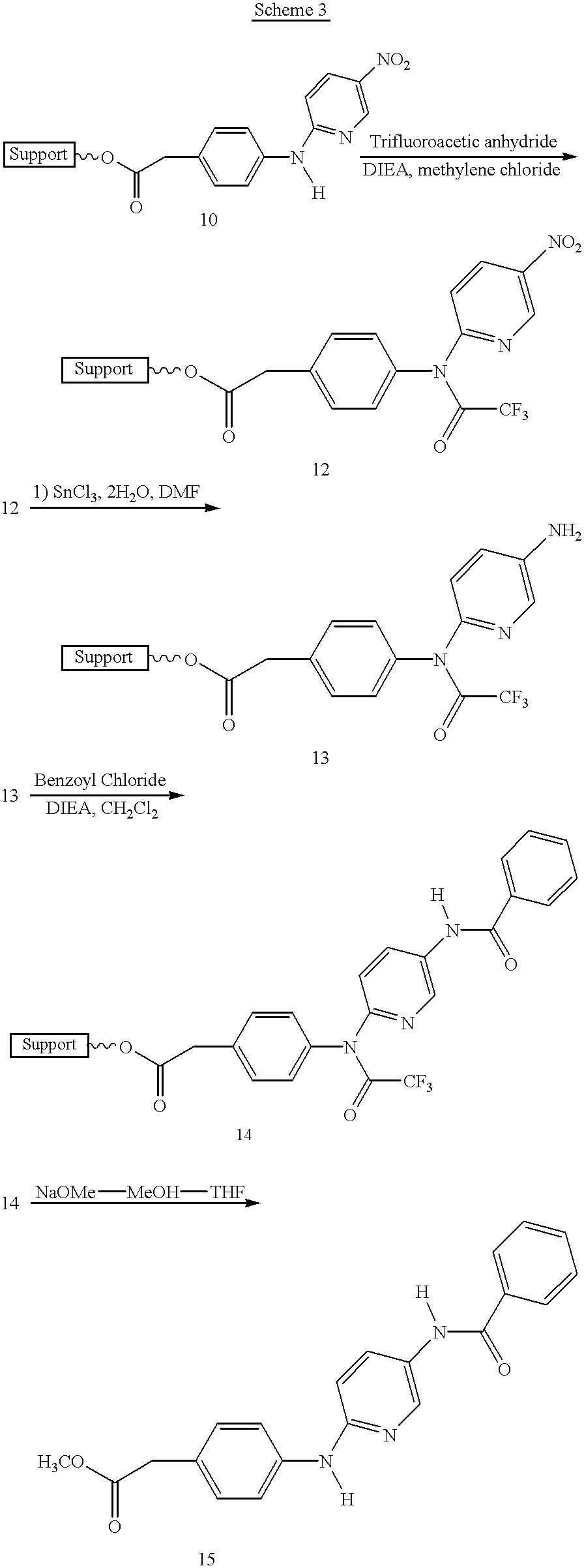

Claims (32)
Priority Applications (1)
| Application Number | Priority Date | Filing Date | Title |
|---|---|---|---|
| US09/049,245 US6277332B1 (en) | 1995-12-18 | 1998-03-27 | Reaction plenum with magnetic separation and/or ultrasonic agitation |
Applications Claiming Priority (3)
| Application Number | Priority Date | Filing Date | Title |
|---|---|---|---|
| US874295P | 1995-12-18 | 1995-12-18 | |
| US08/762,887 US5779985A (en) | 1995-12-18 | 1996-12-07 | Reaction plenum |
| US09/049,245 US6277332B1 (en) | 1995-12-18 | 1998-03-27 | Reaction plenum with magnetic separation and/or ultrasonic agitation |
Related Parent Applications (1)
| Application Number | Title | Priority Date | Filing Date |
|---|---|---|---|
| US08/762,887 Continuation-In-Part US5779985A (en) | 1995-12-18 | 1996-12-07 | Reaction plenum |
Publications (1)
| Publication Number | Publication Date |
|---|---|
| US6277332B1 true US6277332B1 (en) | 2001-08-21 |
Family
ID=46255938
Family Applications (1)
| Application Number | Title | Priority Date | Filing Date |
|---|---|---|---|
| US09/049,245 Expired - Fee Related US6277332B1 (en) | 1995-12-18 | 1998-03-27 | Reaction plenum with magnetic separation and/or ultrasonic agitation |
Country Status (1)
| Country | Link |
|---|---|
| US (1) | US6277332B1 (en) |
Cited By (54)
| Publication number | Priority date | Publication date | Assignee | Title |
|---|---|---|---|---|
| US20020009015A1 (en) * | 1998-10-28 | 2002-01-24 | Laugharn James A. | Method and apparatus for acoustically controlling liquid solutions in microfluidic devices |
| US20020085446A1 (en) * | 1999-06-25 | 2002-07-04 | Avantium International B.V. | Reactor vessel array |
| US20020098117A1 (en) * | 1998-05-01 | 2002-07-25 | Gen-Probe Incorporated | Incubator for use in an automated diagnostic analyzer |
| US6578659B2 (en) * | 2000-12-01 | 2003-06-17 | Misonix Incorporated | Ultrasonic horn assembly |
| US6652992B1 (en) * | 2002-12-20 | 2003-11-25 | Sulphco, Inc. | Corrosion resistant ultrasonic horn |
| WO2003057310A3 (en) * | 2002-01-08 | 2004-02-19 | Kevin R Oldenburg | Liquid sample processing apparatus and method |
| US20040054286A1 (en) * | 2001-11-05 | 2004-03-18 | Audain Vaughn A | Ultrasonic transducing probe with liquid flow-through capability and related automated workstation and methods of using same |
| US6719449B1 (en) * | 1998-10-28 | 2004-04-13 | Covaris, Inc. | Apparatus and method for controlling sonic treatment |
| US20040079580A1 (en) * | 2002-10-28 | 2004-04-29 | Manna Ronald R. | Ultrasonic horn |
| US20050034849A1 (en) * | 2002-01-08 | 2005-02-17 | Oldenburg Kevin R. | Method and apparatus for severing organic molecules by ultrasound |
| US20060024204A1 (en) * | 2004-08-02 | 2006-02-02 | Oldenburg Kevin R | Well plate sealing apparatus and method |
| US20060050605A1 (en) * | 2004-09-08 | 2006-03-09 | Nano-Em Ltd. | High-power sono-chemical reactor |
| US20060158956A1 (en) * | 1998-10-28 | 2006-07-20 | Covaris, Inc. | Methods and systems for modulating acoustic energy delivery |
| US20070053795A1 (en) * | 2005-08-01 | 2007-03-08 | Covaris, Inc. | Methods and systems for compound management and sample preparation |
| US20080031094A1 (en) * | 2006-08-01 | 2008-02-07 | Covaris, Inc. | Methods and apparatus for treating samples with acoustic energy |
| US20080058775A1 (en) * | 2006-08-29 | 2008-03-06 | Darian Alexander L | Ultrasonic debrider probe and method of use |
| AU2006230729B2 (en) * | 1998-05-01 | 2008-04-03 | Gen-Probe Incorporated | Transport mechanism |
| US20090069870A1 (en) * | 2007-09-07 | 2009-03-12 | Steven Haase | Ionic foot bath array |
| US20090117004A1 (en) * | 2007-11-06 | 2009-05-07 | Abbott Laboratories | System for automatically loading immunoassay analyzer |
| US20090181359A1 (en) * | 2007-10-25 | 2009-07-16 | Lou Sheng C | Method of performing ultra-sensitive immunoassays |
| US20100009424A1 (en) * | 2008-07-14 | 2010-01-14 | Natasha Forde | Sonoporation systems and methods |
| US7677120B2 (en) | 2003-12-08 | 2010-03-16 | Covaris, Inc. | Apparatus for sample preparation |
| US20100071793A1 (en) * | 2008-07-25 | 2010-03-25 | Hatch Ltd. | Apparatus for stabilization and deceleration of supersonic flow incorporating a diverging nozzle and perforated plate |
| WO2010102301A1 (en) * | 2009-03-06 | 2010-09-10 | Jennifer Hollenstein | Method and apparatus for suspending magnetic microparticles |
| US7794659B2 (en) | 2005-03-10 | 2010-09-14 | Gen-Probe Incorporated | Signal measuring system having a movable signal measuring device |
| US20110018368A1 (en) * | 2008-02-22 | 2011-01-27 | M.Rkisches Werk Gmbh | High-performance ultrasonic transducer and method for the production thereof |
| US7931611B2 (en) | 2005-03-23 | 2011-04-26 | Misonix, Incorporated | Ultrasonic wound debrider probe and method of use |
| US7981368B2 (en) | 1998-10-28 | 2011-07-19 | Covaris, Inc. | Method and apparatus for acoustically controlling liquid solutions in microfluidic devices |
| US8192992B2 (en) | 1998-05-01 | 2012-06-05 | Gen-Probe Incorporated | System and method for incubating the contents of a reaction receptacle |
| US8211386B2 (en) | 2004-06-08 | 2012-07-03 | Biokit, S.A. | Tapered cuvette and method of collecting magnetic particles |
| US8459121B2 (en) | 2010-10-28 | 2013-06-11 | Covaris, Inc. | Method and system for acoustically treating material |
| AT13317U1 (en) * | 2011-08-29 | 2013-10-15 | Andrey Aleksandrovich Getalov | Method for the simultaneous ultrasonic cavitation treatment of liquid media of different composition |
| US8702836B2 (en) | 2006-11-22 | 2014-04-22 | Covaris, Inc. | Methods and apparatus for treating samples with acoustic energy to form particles and particulates |
| US8709359B2 (en) | 2011-01-05 | 2014-04-29 | Covaris, Inc. | Sample holder and method for treating sample material |
| US8718948B2 (en) | 2011-02-24 | 2014-05-06 | Gen-Probe Incorporated | Systems and methods for distinguishing optical signals of different modulation frequencies in an optical signal detector |
| US8827193B2 (en) | 2010-05-07 | 2014-09-09 | B9 Plasma, Inc. | Controlled bubble collapse milling |
| US8840848B2 (en) | 2010-07-23 | 2014-09-23 | Beckman Coulter, Inc. | System and method including analytical units |
| EP2815808A1 (en) * | 2012-05-21 | 2014-12-24 | Cavitanica Ltd. | Method for the simultaneous ultrasonic cavitation treatment of containers of liquid media |
| US8973736B2 (en) | 2011-11-07 | 2015-03-10 | Beckman Coulter, Inc. | Magnetic damping for specimen transport system |
| US9046506B2 (en) | 2011-11-07 | 2015-06-02 | Beckman Coulter, Inc. | Specimen container detection |
| US9046507B2 (en) | 2010-07-29 | 2015-06-02 | Gen-Probe Incorporated | Method, system and apparatus for incorporating capacitive proximity sensing in an automated fluid transfer procedure |
| US9329194B2 (en) | 2007-11-05 | 2016-05-03 | Abbott Laboratories | Automated analyzer for clinical laboratory |
| US9335338B2 (en) | 2013-03-15 | 2016-05-10 | Toshiba Medical Systems Corporation | Automated diagnostic analyzers having rear accessible track systems and related methods |
| US9400285B2 (en) | 2013-03-15 | 2016-07-26 | Abbot Laboratories | Automated diagnostic analyzers having vertically arranged carousels and related methods |
| US9446418B2 (en) | 2011-11-07 | 2016-09-20 | Beckman Coulter, Inc. | Robotic arm |
| US9482684B2 (en) | 2011-11-07 | 2016-11-01 | Beckman Coulter, Inc. | Centrifuge system and workflow |
| US9506943B2 (en) | 2011-11-07 | 2016-11-29 | Beckman Coulter, Inc. | Aliquotter system and workflow |
| US20160354739A1 (en) * | 2011-02-16 | 2016-12-08 | Senostic Gmbh | Device and method for production and analysis of prions |
| WO2017184972A1 (en) * | 2016-04-22 | 2017-10-26 | Protein Dynamic Solutions Llc | Liquid handling system and method |
| US9910054B2 (en) | 2011-11-07 | 2018-03-06 | Beckman Coulter, Inc. | System and method for processing samples |
| US10001497B2 (en) | 2013-03-15 | 2018-06-19 | Abbott Laboratories | Diagnostic analyzers with pretreatment carousels and related methods |
| US10427162B2 (en) | 2016-12-21 | 2019-10-01 | Quandx Inc. | Systems and methods for molecular diagnostics |
| WO2020148463A1 (en) * | 2019-01-15 | 2020-07-23 | Oliver Johannes Kreuzer | Process for solid-phase peptide synthesis and device |
| US20230209033A1 (en) * | 2018-08-17 | 2023-06-29 | Sierra Biosystems, Inc. | Row-independent oligonucleotide synthesis |
Citations (24)
| Publication number | Priority date | Publication date | Assignee | Title |
|---|---|---|---|---|
| US1734975A (en) * | 1927-09-02 | 1929-11-12 | Alfred L Loomis | Method and apparatus for forming emulsions and the like |
| US3301535A (en) * | 1966-01-04 | 1967-01-31 | American Sterilizer Co | Ultrasonic washing machine and transducer therefor |
| US3325976A (en) * | 1966-04-26 | 1967-06-20 | Beckman Instruments Inc | Sample atomizer |
| US3552536A (en) | 1969-04-15 | 1971-01-05 | Gilford Instr Labor Inc | Test sample carrier transport apparatus |
| US3811623A (en) | 1972-12-04 | 1974-05-21 | R Speer | Process and apparatus for separation of mineral ore from gangue material |
| US3837805A (en) | 1971-01-15 | 1974-09-24 | Wave Energy Systems | Apparatus for continuous sterilization at low temperature |
| US3951605A (en) | 1974-08-08 | 1976-04-20 | Rohe Scientific Corporation | Instrument for automated immunochemical analysis |
| US4022579A (en) | 1975-11-12 | 1977-05-10 | Micromedic Systems, Inc. | Transport system for analytical equipment |
| US4259290A (en) | 1978-07-05 | 1981-03-31 | Kommandiittiyhtio Finnpipette Osmo A. Suovaniemi | Transfer device for analysis equipment |
| WO1983003920A1 (en) | 1982-04-23 | 1983-11-10 | Sintef | Magnetic polymer particles and process for the preparation thereof |
| US4582990A (en) | 1980-10-27 | 1986-04-15 | Randam Electronics, Inc. | Analytical instrument with two moving trains of sample holder-carrying trays under microprocessor control |
| EP0211436A2 (en) | 1985-08-07 | 1987-02-25 | Tosoh Corporation | Stirrer for biochemical reactions |
| US4919807A (en) | 1986-07-16 | 1990-04-24 | Heritage Industries, Inc. | Ultrasonic vibrator tray apparatus |
| US4973876A (en) * | 1989-09-20 | 1990-11-27 | Branson Ultrasonics Corporation | Ultrasonic power supply |
| US5176446A (en) * | 1989-10-16 | 1993-01-05 | Shigeru Chiba | Magnetic type agitator which is capable of generating ultrasonic wave |
| US5206171A (en) * | 1990-12-17 | 1993-04-27 | Her Majesty The Queen In Right Of Canada | Programmable automated inoculator/replicator |
| WO1993025912A2 (en) | 1992-06-09 | 1993-12-23 | Medical Research Council | Automated preparation of nucleic acids |
| US5380487A (en) | 1992-05-05 | 1995-01-10 | Pasteur Sanofi Diagnostics | Device for automatic chemical analysis |
| US5413770A (en) * | 1992-08-12 | 1995-05-09 | Kabushiki Kaisha Toshiba | Stirring apparatus for an automatic chemical analysis system |
| US5446263A (en) | 1988-11-03 | 1995-08-29 | Max-Planck-Gesellschaft Zur Forderung Der Wissenschaften E.V. | Device for setting the temperature of a sample selectively to different values |
| US5496517A (en) | 1989-12-22 | 1996-03-05 | Beckman Instruments, Inc. | Laboratory workstation using thermal vaporization control |
| US5722444A (en) * | 1996-03-26 | 1998-03-03 | Trident Technologies Unlimited, Inc. | Rigid ultrasonic radiation plate assembly systems for ultrasonic cleaning tanks |
| US5736100A (en) * | 1994-09-20 | 1998-04-07 | Hitachi, Ltd. | Chemical analyzer non-invasive stirrer |
| US5779985A (en) * | 1995-12-18 | 1998-07-14 | Solid Phase Sciences Corporation | Reaction plenum |
-
1998
- 1998-03-27 US US09/049,245 patent/US6277332B1/en not_active Expired - Fee Related
Patent Citations (24)
| Publication number | Priority date | Publication date | Assignee | Title |
|---|---|---|---|---|
| US1734975A (en) * | 1927-09-02 | 1929-11-12 | Alfred L Loomis | Method and apparatus for forming emulsions and the like |
| US3301535A (en) * | 1966-01-04 | 1967-01-31 | American Sterilizer Co | Ultrasonic washing machine and transducer therefor |
| US3325976A (en) * | 1966-04-26 | 1967-06-20 | Beckman Instruments Inc | Sample atomizer |
| US3552536A (en) | 1969-04-15 | 1971-01-05 | Gilford Instr Labor Inc | Test sample carrier transport apparatus |
| US3837805A (en) | 1971-01-15 | 1974-09-24 | Wave Energy Systems | Apparatus for continuous sterilization at low temperature |
| US3811623A (en) | 1972-12-04 | 1974-05-21 | R Speer | Process and apparatus for separation of mineral ore from gangue material |
| US3951605A (en) | 1974-08-08 | 1976-04-20 | Rohe Scientific Corporation | Instrument for automated immunochemical analysis |
| US4022579A (en) | 1975-11-12 | 1977-05-10 | Micromedic Systems, Inc. | Transport system for analytical equipment |
| US4259290A (en) | 1978-07-05 | 1981-03-31 | Kommandiittiyhtio Finnpipette Osmo A. Suovaniemi | Transfer device for analysis equipment |
| US4582990A (en) | 1980-10-27 | 1986-04-15 | Randam Electronics, Inc. | Analytical instrument with two moving trains of sample holder-carrying trays under microprocessor control |
| WO1983003920A1 (en) | 1982-04-23 | 1983-11-10 | Sintef | Magnetic polymer particles and process for the preparation thereof |
| EP0211436A2 (en) | 1985-08-07 | 1987-02-25 | Tosoh Corporation | Stirrer for biochemical reactions |
| US4919807A (en) | 1986-07-16 | 1990-04-24 | Heritage Industries, Inc. | Ultrasonic vibrator tray apparatus |
| US5446263A (en) | 1988-11-03 | 1995-08-29 | Max-Planck-Gesellschaft Zur Forderung Der Wissenschaften E.V. | Device for setting the temperature of a sample selectively to different values |
| US4973876A (en) * | 1989-09-20 | 1990-11-27 | Branson Ultrasonics Corporation | Ultrasonic power supply |
| US5176446A (en) * | 1989-10-16 | 1993-01-05 | Shigeru Chiba | Magnetic type agitator which is capable of generating ultrasonic wave |
| US5496517A (en) | 1989-12-22 | 1996-03-05 | Beckman Instruments, Inc. | Laboratory workstation using thermal vaporization control |
| US5206171A (en) * | 1990-12-17 | 1993-04-27 | Her Majesty The Queen In Right Of Canada | Programmable automated inoculator/replicator |
| US5380487A (en) | 1992-05-05 | 1995-01-10 | Pasteur Sanofi Diagnostics | Device for automatic chemical analysis |
| WO1993025912A2 (en) | 1992-06-09 | 1993-12-23 | Medical Research Council | Automated preparation of nucleic acids |
| US5413770A (en) * | 1992-08-12 | 1995-05-09 | Kabushiki Kaisha Toshiba | Stirring apparatus for an automatic chemical analysis system |
| US5736100A (en) * | 1994-09-20 | 1998-04-07 | Hitachi, Ltd. | Chemical analyzer non-invasive stirrer |
| US5779985A (en) * | 1995-12-18 | 1998-07-14 | Solid Phase Sciences Corporation | Reaction plenum |
| US5722444A (en) * | 1996-03-26 | 1998-03-03 | Trident Technologies Unlimited, Inc. | Rigid ultrasonic radiation plate assembly systems for ultrasonic cleaning tanks |
Non-Patent Citations (10)
| Title |
|---|
| Analytical Biochemistry 170, 341-348, Academic Press, Inc., 1988, Bethesda, MD. |
| Diversomer 8-Pin Synthesizer, catalog, Chemglass, Vineland, New Jersey, USA, 1996. |
| Jan G. Fjeld, et al. In Vivo Evaluation of Radio-labelled Antibodies With Antigen-Coated Polymer Particles in Diffusion Chambers, Journal of Immuno-logical Methods, 109, 1988, pp. 1-7 Elsevier Science Publishers, Amsterdam, The Netherlands. |
| Kenneth S. Suslick, Sonochemistry, Science, vol. 24, pp. 1439-1445, Mar. 23, 1990, American Association For the Advancement of Science, USA. |
| Raji Padmanabhan, et al, Purification of Transiently Transfected Cells By Magnetic Affinity Cell Sorting. |
| Sayomi Takahashi and Yasutsugu Shimonishi, Solid Phase Peptide Synthesis Using Ultrasonic Waves, Chemistry Letters, 1974, pp. 51-56, Chemical Society of Japan. |
| Stefan Miltenyi, et al, High Gradient Magnetic Cell Separation With MACS, Cytomery 11:231-238, 1990, Wiley-Liss, Inc., West Germany. |
| Timothy J. Mason, Practical Sonochemistry, User's Guide to Applications in Chemistry and Chemical Engineering, Ellis Horwood, London, ch. 2, pp. 56-59. |
| Treleaven, et al, Removal of Neuroblastoma Cells From Bone Marrow With Monoclonal Antibodies Conjugates to Magnetic Microspheres, The Lancet, Jan. 14, 1984, pp. 70-73. |
| Trevor L. Hawkins, et al, DNA Purification and Isolation Using a Solid-Phase, Nucleic Acids Re-search, vol. 22, No. 21 pp. 4543-4544, 1994, USA. |
Cited By (128)
| Publication number | Priority date | Publication date | Assignee | Title |
|---|---|---|---|---|
| US9598723B2 (en) | 1998-05-01 | 2017-03-21 | Gen-Probe Incorporated | Automated analyzer for performing a nucleic acid-based assay |
| US8137620B2 (en) | 1998-05-01 | 2012-03-20 | Gen-Probe Incorporated | Temperature-controlled incubator having an arcuate closure panel |
| US20020098117A1 (en) * | 1998-05-01 | 2002-07-25 | Gen-Probe Incorporated | Incubator for use in an automated diagnostic analyzer |
| US8192992B2 (en) | 1998-05-01 | 2012-06-05 | Gen-Probe Incorporated | System and method for incubating the contents of a reaction receptacle |
| US8221682B2 (en) | 1998-05-01 | 2012-07-17 | Gen-Probe Incorporated | System for incubating the contents of a reaction receptacle |
| US8309358B2 (en) | 1998-05-01 | 2012-11-13 | Gen-Probe Incorporated | Method for introducing a fluid into a reaction receptacle contained within a temperature-controlled environment |
| US8318500B2 (en) | 1998-05-01 | 2012-11-27 | Gen-Probe, Incorporated | Method for agitating the contents of a reaction receptacle within a temperature-controlled environment |
| US8337753B2 (en) | 1998-05-01 | 2012-12-25 | Gen-Probe Incorporated | Temperature-controlled incubator having a receptacle mixing mechanism |
| US7666602B2 (en) | 1998-05-01 | 2010-02-23 | Gen-Probe Incorporated | Method for agitating the fluid contents of a container |
| US6764649B2 (en) * | 1998-05-01 | 2004-07-20 | Gen-Probe Incorporated | Transport mechanism |
| US7666681B2 (en) | 1998-05-01 | 2010-02-23 | Gen-Probe Incorporated | Method for agitating the fluid contents of a container |
| US8546110B2 (en) | 1998-05-01 | 2013-10-01 | Gen-Probe Incorporated | Method for detecting the presence of a nucleic acid in a sample |
| US8569019B2 (en) | 1998-05-01 | 2013-10-29 | Gen-Probe Incorporated | Method for performing an assay with a nucleic acid present in a specimen |
| US8012419B2 (en) | 1998-05-01 | 2011-09-06 | Gen-Probe Incorporated | Temperature-controlled incubator having rotatable door |
| US8569020B2 (en) | 1998-05-01 | 2013-10-29 | Gen-Probe Incorporated | Method for simultaneously performing multiple amplification reactions |
| US8709814B2 (en) | 1998-05-01 | 2014-04-29 | Gen-Probe Incorporated | Method for incubating the contents of a receptacle |
| AU2006230729B2 (en) * | 1998-05-01 | 2008-04-03 | Gen-Probe Incorporated | Transport mechanism |
| US8883455B2 (en) | 1998-05-01 | 2014-11-11 | Gen-Probe Incorporated | Method for detecting the presence of a nucleic acid in a sample |
| US9150908B2 (en) | 1998-05-01 | 2015-10-06 | Gen-Probe Incorporated | Method for detecting the presence of a nucleic acid in a sample |
| US6948843B2 (en) | 1998-10-28 | 2005-09-27 | Covaris, Inc. | Method and apparatus for acoustically controlling liquid solutions in microfluidic devices |
| US7521023B2 (en) | 1998-10-28 | 2009-04-21 | Covaris, Inc. | Apparatus and methods for controlling sonic treatment |
| US7329039B2 (en) | 1998-10-28 | 2008-02-12 | Covaris, Inc. | Systems and methods for determining a state of fluidization and/or a state of mixing |
| US20080050289A1 (en) * | 1998-10-28 | 2008-02-28 | Laugharn James A Jr | Apparatus and methods for controlling sonic treatment |
| US7981368B2 (en) | 1998-10-28 | 2011-07-19 | Covaris, Inc. | Method and apparatus for acoustically controlling liquid solutions in microfluidic devices |
| US20080056960A1 (en) * | 1998-10-28 | 2008-03-06 | Laugharn James A Jr | Methods and systems for modulating acoustic energy delivery |
| US7687039B2 (en) | 1998-10-28 | 2010-03-30 | Covaris, Inc. | Methods and systems for modulating acoustic energy delivery |
| US7687026B2 (en) | 1998-10-28 | 2010-03-30 | Covaris, Inc. | Apparatus and methods for controlling sonic treatment |
| US20060029525A1 (en) * | 1998-10-28 | 2006-02-09 | Laugharn James A Jr | Method and apparatus for acoustically controlling liquid solutions in microfluidic devices |
| US7686500B2 (en) | 1998-10-28 | 2010-03-30 | Covaris, Inc. | Method and apparatus for acoustically controlling liquid solutions in microfluidic devices |
| US8263005B2 (en) | 1998-10-28 | 2012-09-11 | Covaris, Inc. | Methods and systems for modulating acoustic energy delivery |
| US20050150830A1 (en) * | 1998-10-28 | 2005-07-14 | Covaris, Inc. | Systems and methods for determining a state of fluidization and/or a state of mixing |
| US7811525B2 (en) | 1998-10-28 | 2010-10-12 | Covaris, Inc. | Methods and systems for modulating acoustic energy delivery |
| US20040264293A1 (en) * | 1998-10-28 | 2004-12-30 | Covaris, Inc. | Apparatus and methods for controlling sonic treatment |
| US20060158956A1 (en) * | 1998-10-28 | 2006-07-20 | Covaris, Inc. | Methods and systems for modulating acoustic energy delivery |
| US6719449B1 (en) * | 1998-10-28 | 2004-04-13 | Covaris, Inc. | Apparatus and method for controlling sonic treatment |
| US20020009015A1 (en) * | 1998-10-28 | 2002-01-24 | Laugharn James A. | Method and apparatus for acoustically controlling liquid solutions in microfluidic devices |
| US20020085446A1 (en) * | 1999-06-25 | 2002-07-04 | Avantium International B.V. | Reactor vessel array |
| US6578659B2 (en) * | 2000-12-01 | 2003-06-17 | Misonix Incorporated | Ultrasonic horn assembly |
| US20040054286A1 (en) * | 2001-11-05 | 2004-03-18 | Audain Vaughn A | Ultrasonic transducing probe with liquid flow-through capability and related automated workstation and methods of using same |
| US20050034849A1 (en) * | 2002-01-08 | 2005-02-17 | Oldenburg Kevin R. | Method and apparatus for severing organic molecules by ultrasound |
| WO2003057310A3 (en) * | 2002-01-08 | 2004-02-19 | Kevin R Oldenburg | Liquid sample processing apparatus and method |
| US7373968B2 (en) | 2002-01-08 | 2008-05-20 | Kevin R. Oldenburg | Method and apparatus for manipulating an organic liquid sample |
| US20040079580A1 (en) * | 2002-10-28 | 2004-04-29 | Manna Ronald R. | Ultrasonic horn |
| US7004282B2 (en) | 2002-10-28 | 2006-02-28 | Misonix, Incorporated | Ultrasonic horn |
| US6652992B1 (en) * | 2002-12-20 | 2003-11-25 | Sulphco, Inc. | Corrosion resistant ultrasonic horn |
| US7677120B2 (en) | 2003-12-08 | 2010-03-16 | Covaris, Inc. | Apparatus for sample preparation |
| US8476080B2 (en) | 2004-06-08 | 2013-07-02 | Biokit, S.A. | Tapered cuvette and method of collecting magnetic particles |
| US8211386B2 (en) | 2004-06-08 | 2012-07-03 | Biokit, S.A. | Tapered cuvette and method of collecting magnetic particles |
| US20060024204A1 (en) * | 2004-08-02 | 2006-02-02 | Oldenburg Kevin R | Well plate sealing apparatus and method |
| US20060050605A1 (en) * | 2004-09-08 | 2006-03-09 | Nano-Em Ltd. | High-power sono-chemical reactor |
| US8501461B2 (en) | 2005-03-10 | 2013-08-06 | Gen-Probe Incorporated | System for performing multi-formatted assays |
| US10006862B2 (en) | 2005-03-10 | 2018-06-26 | Gen-Probe Incorporated | Continuous process for performing multiple nucleic acid amplification assays |
| US7964413B2 (en) | 2005-03-10 | 2011-06-21 | Gen-Probe Incorporated | Method for continuous mode processing of multiple reaction receptacles in a real-time amplification assay |
| US8008066B2 (en) | 2005-03-10 | 2011-08-30 | Gen-Probe Incorporated | System for performing multi-formatted assays |
| US7932081B2 (en) | 2005-03-10 | 2011-04-26 | Gen-Probe Incorporated | Signal measuring system for conducting real-time amplification assays |
| US9372156B2 (en) | 2005-03-10 | 2016-06-21 | Gen-Probe Incorporated | System for processing contents of a receptacle to detect an optical signal emitted by the contents |
| US7897337B2 (en) | 2005-03-10 | 2011-03-01 | Gen-Probe Incorporated | Method for performing multi-formatted assays |
| US8663922B2 (en) | 2005-03-10 | 2014-03-04 | Gen-Probe Incorporated | Systems and methods for detecting multiple optical signals |
| US7794659B2 (en) | 2005-03-10 | 2010-09-14 | Gen-Probe Incorporated | Signal measuring system having a movable signal measuring device |
| US8615368B2 (en) | 2005-03-10 | 2013-12-24 | Gen-Probe Incorporated | Method for determining the amount of an analyte in a sample |
| US8349564B2 (en) | 2005-03-10 | 2013-01-08 | Gen-Probe Incorporated | Method for continuous mode processing of the contents of multiple reaction receptacles in a real-time amplification assay |
| US9726607B2 (en) | 2005-03-10 | 2017-08-08 | Gen-Probe Incorporated | Systems and methods for detecting multiple optical signals |
| US7931611B2 (en) | 2005-03-23 | 2011-04-26 | Misonix, Incorporated | Ultrasonic wound debrider probe and method of use |
| US20070053795A1 (en) * | 2005-08-01 | 2007-03-08 | Covaris, Inc. | Methods and systems for compound management and sample preparation |
| US7757561B2 (en) | 2005-08-01 | 2010-07-20 | Covaris, Inc. | Methods and systems for processing samples using acoustic energy |
| US20080031094A1 (en) * | 2006-08-01 | 2008-02-07 | Covaris, Inc. | Methods and apparatus for treating samples with acoustic energy |
| US8353619B2 (en) | 2006-08-01 | 2013-01-15 | Covaris, Inc. | Methods and apparatus for treating samples with acoustic energy |
| US20080058775A1 (en) * | 2006-08-29 | 2008-03-06 | Darian Alexander L | Ultrasonic debrider probe and method of use |
| US8702836B2 (en) | 2006-11-22 | 2014-04-22 | Covaris, Inc. | Methods and apparatus for treating samples with acoustic energy to form particles and particulates |
| US20090069870A1 (en) * | 2007-09-07 | 2009-03-12 | Steven Haase | Ionic foot bath array |
| US20090181359A1 (en) * | 2007-10-25 | 2009-07-16 | Lou Sheng C | Method of performing ultra-sensitive immunoassays |
| US9329194B2 (en) | 2007-11-05 | 2016-05-03 | Abbott Laboratories | Automated analyzer for clinical laboratory |
| US8691149B2 (en) * | 2007-11-06 | 2014-04-08 | Abbott Laboratories | System for automatically loading immunoassay analyzer |
| US20090117004A1 (en) * | 2007-11-06 | 2009-05-07 | Abbott Laboratories | System for automatically loading immunoassay analyzer |
| US20110018368A1 (en) * | 2008-02-22 | 2011-01-27 | M.Rkisches Werk Gmbh | High-performance ultrasonic transducer and method for the production thereof |
| US7928614B2 (en) * | 2008-02-22 | 2011-04-19 | Markisches Werk Gmbh | High-performance ultrasonic transducer and method for the production thereof |
| US20100009424A1 (en) * | 2008-07-14 | 2010-01-14 | Natasha Forde | Sonoporation systems and methods |
| US8176941B2 (en) | 2008-07-25 | 2012-05-15 | Hatch Ltd. | Apparatus for stabilization and deceleration of supersonic flow incorporating a diverging nozzle and perforated plate |
| US20100071793A1 (en) * | 2008-07-25 | 2010-03-25 | Hatch Ltd. | Apparatus for stabilization and deceleration of supersonic flow incorporating a diverging nozzle and perforated plate |
| WO2010102301A1 (en) * | 2009-03-06 | 2010-09-10 | Jennifer Hollenstein | Method and apparatus for suspending magnetic microparticles |
| US8827193B2 (en) | 2010-05-07 | 2014-09-09 | B9 Plasma, Inc. | Controlled bubble collapse milling |
| US9140715B2 (en) | 2010-07-23 | 2015-09-22 | Beckman Coulter, Inc. | System and method for controlling thermal cycler modules |
| US9285382B2 (en) | 2010-07-23 | 2016-03-15 | Beckman Coulter, Inc. | Reaction vessel |
| US8932541B2 (en) | 2010-07-23 | 2015-01-13 | Beckman Coulter, Inc. | Pipettor including compliant coupling |
| US8956570B2 (en) | 2010-07-23 | 2015-02-17 | Beckman Coulter, Inc. | System and method including analytical units |
| US8962308B2 (en) | 2010-07-23 | 2015-02-24 | Beckman Coulter, Inc. | System and method including thermal cycler modules |
| US9274132B2 (en) | 2010-07-23 | 2016-03-01 | Beckman Coulter, Inc. | Assay cartridge with reaction well |
| US8996320B2 (en) | 2010-07-23 | 2015-03-31 | Beckman Coulter, Inc. | System and method including analytical units |
| US8840848B2 (en) | 2010-07-23 | 2014-09-23 | Beckman Coulter, Inc. | System and method including analytical units |
| US9519000B2 (en) | 2010-07-23 | 2016-12-13 | Beckman Coulter, Inc. | Reagent cartridge |
| US9046455B2 (en) | 2010-07-23 | 2015-06-02 | Beckman Coulter, Inc. | System and method including multiple processing lanes executing processing protocols |
| US9046507B2 (en) | 2010-07-29 | 2015-06-02 | Gen-Probe Incorporated | Method, system and apparatus for incorporating capacitive proximity sensing in an automated fluid transfer procedure |
| US8991259B2 (en) | 2010-10-28 | 2015-03-31 | Covaris, Inc. | Method and system for acoustically treating material |
| US8459121B2 (en) | 2010-10-28 | 2013-06-11 | Covaris, Inc. | Method and system for acoustically treating material |
| US9126177B2 (en) | 2010-10-28 | 2015-09-08 | Covaris, Inc. | Method and system for acoustically treating material |
| US8709359B2 (en) | 2011-01-05 | 2014-04-29 | Covaris, Inc. | Sample holder and method for treating sample material |
| US20160354739A1 (en) * | 2011-02-16 | 2016-12-08 | Senostic Gmbh | Device and method for production and analysis of prions |
| US10449499B2 (en) * | 2011-02-16 | 2019-10-22 | Senostic Health Gmbh | Device and method for production and analysis of prions |
| US10641707B2 (en) | 2011-02-24 | 2020-05-05 | Gen-Probe Incorporated | Systems and methods for distinguishing optical signals of different modulation frequencies in an optical signal detector |
| US9915613B2 (en) | 2011-02-24 | 2018-03-13 | Gen-Probe Incorporated | Systems and methods for distinguishing optical signals of different modulation frequencies in an optical signal detector |
| US8718948B2 (en) | 2011-02-24 | 2014-05-06 | Gen-Probe Incorporated | Systems and methods for distinguishing optical signals of different modulation frequencies in an optical signal detector |
| AT13317U1 (en) * | 2011-08-29 | 2013-10-15 | Andrey Aleksandrovich Getalov | Method for the simultaneous ultrasonic cavitation treatment of liquid media of different composition |
| AT13317U8 (en) * | 2011-08-29 | 2014-01-15 | Andrey Aleksandrovich Getalov | Method for the simultaneous ultrasonic cavitation treatment of liquid media of different composition |
| US9910054B2 (en) | 2011-11-07 | 2018-03-06 | Beckman Coulter, Inc. | System and method for processing samples |
| US10048284B2 (en) | 2011-11-07 | 2018-08-14 | Beckman Coulter, Inc. | Sample container cap with centrifugation status indicator device |
| US9482684B2 (en) | 2011-11-07 | 2016-11-01 | Beckman Coulter, Inc. | Centrifuge system and workflow |
| US9446418B2 (en) | 2011-11-07 | 2016-09-20 | Beckman Coulter, Inc. | Robotic arm |
| US9046506B2 (en) | 2011-11-07 | 2015-06-02 | Beckman Coulter, Inc. | Specimen container detection |
| US8973736B2 (en) | 2011-11-07 | 2015-03-10 | Beckman Coulter, Inc. | Magnetic damping for specimen transport system |
| US10274505B2 (en) | 2011-11-07 | 2019-04-30 | Beckman Coulter, Inc. | Robotic arm |
| US9506943B2 (en) | 2011-11-07 | 2016-11-29 | Beckman Coulter, Inc. | Aliquotter system and workflow |
| EP2815808A1 (en) * | 2012-05-21 | 2014-12-24 | Cavitanica Ltd. | Method for the simultaneous ultrasonic cavitation treatment of containers of liquid media |
| EP2815808A4 (en) * | 2012-05-21 | 2014-12-31 | Cavitanica Ltd | Method for the simultaneous ultrasonic cavitation treatment of containers of liquid media |
| US11435372B2 (en) | 2013-03-15 | 2022-09-06 | Abbott Laboratories | Diagnostic analyzers with pretreatment carousels and related methods |
| US10001497B2 (en) | 2013-03-15 | 2018-06-19 | Abbott Laboratories | Diagnostic analyzers with pretreatment carousels and related methods |
| US10267818B2 (en) | 2013-03-15 | 2019-04-23 | Abbott Laboratories | Automated diagnostic analyzers having rear accessible track systems and related methods |
| US9335338B2 (en) | 2013-03-15 | 2016-05-10 | Toshiba Medical Systems Corporation | Automated diagnostic analyzers having rear accessible track systems and related methods |
| US11536739B2 (en) | 2013-03-15 | 2022-12-27 | Abbott Laboratories | Automated diagnostic analyzers having vertically arranged carousels and related methods |
| US10197585B2 (en) | 2013-03-15 | 2019-02-05 | Abbott Laboratories | Automated diagnostic analyzers having vertically arranged carousels and related methods |
| US10775398B2 (en) | 2013-03-15 | 2020-09-15 | Abbott Laboratories | Automated diagnostic analyzers having vertically arranged carousels and related methods |
| US9400285B2 (en) | 2013-03-15 | 2016-07-26 | Abbot Laboratories | Automated diagnostic analyzers having vertically arranged carousels and related methods |
| US11125766B2 (en) | 2013-03-15 | 2021-09-21 | Abbott Laboratories | Automated diagnostic analyzers having rear accessible track systems and related methods |
| WO2017184972A1 (en) * | 2016-04-22 | 2017-10-26 | Protein Dynamic Solutions Llc | Liquid handling system and method |
| US10427162B2 (en) | 2016-12-21 | 2019-10-01 | Quandx Inc. | Systems and methods for molecular diagnostics |
| US20230209033A1 (en) * | 2018-08-17 | 2023-06-29 | Sierra Biosystems, Inc. | Row-independent oligonucleotide synthesis |
| US11856177B2 (en) * | 2018-08-17 | 2023-12-26 | Sierra Biosystems, Inc. | Row-independent oligonucleotide synthesis |
| CN113646322A (en) * | 2019-01-15 | 2021-11-12 | 奥利弗·约翰内斯·克鲁泽 | Solid phase peptide synthesis method and device |
| WO2020148463A1 (en) * | 2019-01-15 | 2020-07-23 | Oliver Johannes Kreuzer | Process for solid-phase peptide synthesis and device |
Similar Documents
| Publication | Publication Date | Title |
|---|---|---|
| US6277332B1 (en) | Reaction plenum with magnetic separation and/or ultrasonic agitation | |
| US5779985A (en) | Reaction plenum | |
| AU2022201238B2 (en) | Flow cells utilizing surface-attached structures, and related systems and methods | |
| US20210341554A1 (en) | Rapid magnetic biosensor | |
| US4895650A (en) | Magnetic separation rack for diagnostic assays | |
| US6409925B1 (en) | Device and system for transfer of material | |
| JP4486964B2 (en) | Method and apparatus for detecting substances or analytes from analysis of one or more samples | |
| JP3962789B2 (en) | Mixing / separating apparatus and method using magnetic particles | |
| US20110137018A1 (en) | Magnetic separation system with pre and post processing modules | |
| US20030040129A1 (en) | Binding assays using magnetically immobilized arrays | |
| US20110127222A1 (en) | Trapping magnetic cell sorting system | |
| US20210316303A1 (en) | Flow cells utilizing surface-attached structures, and related systems and methods | |
| JPH09329602A (en) | Minute material holding carrier, its suspension system, minute material handling equipment and minute material position control method | |
| US20100213136A1 (en) | Apparatus for moving magnetic particles | |
| US5835329A (en) | Apparatus for agitation separation of magnetic particles | |
| US20210220827A1 (en) | Systems and methods for nucleic acid purification using flow cells with actuated surface-attached structures | |
| WO2023137139A2 (en) | Mechanical microfluidic manipulation | |
| US20030153024A1 (en) | Charged bio-molecule/binding agent conjugate for biological capture | |
| US7329392B2 (en) | Device and method for handling reaction components |
Legal Events
| Date | Code | Title | Description |
|---|---|---|---|
| AS | Assignment |
Owner name: SOLID PHASE SCIENCES CORPORATION, MASSACHUSETTS Free format text: ASSIGNMENT OF ASSIGNORS INTEREST;ASSIGNOR:SUCHOLEIKI, IRVING;REEL/FRAME:009062/0001 Effective date: 19980327 |
|
| AS | Assignment |
Owner name: MDS PROTEOMICS INC., CANADA Free format text: ASSIGNMENT OF ASSIGNORS INTEREST;ASSIGNOR:SOLID PHASE SCIENCES CORPORATION;REEL/FRAME:013634/0197 Effective date: 20030106 |
|
| FEPP | Fee payment procedure |
Free format text: PAT HOLDER NO LONGER CLAIMS SMALL ENTITY STATUS, ENTITY STATUS SET TO UNDISCOUNTED (ORIGINAL EVENT CODE: STOL); ENTITY STATUS OF PATENT OWNER: LARGE ENTITY |
|
| REFU | Refund |
Free format text: REFUND - SURCHARGE, PETITION TO ACCEPT PYMT AFTER EXP, UNINTENTIONAL (ORIGINAL EVENT CODE: R2551); ENTITY STATUS OF PATENT OWNER: LARGE ENTITY |
|
| FPAY | Fee payment |
Year of fee payment: 4 |
|
| AS | Assignment |
Owner name: PROTANA INC., CANADA Free format text: ASSIGNMENT OF ASSIGNORS INTEREST;ASSIGNOR:MDS PROTEOMICS, INC.;REEL/FRAME:016651/0370 Effective date: 20040729 |
|
| REMI | Maintenance fee reminder mailed | ||
| LAPS | Lapse for failure to pay maintenance fees | ||
| STCH | Information on status: patent discontinuation |
Free format text: PATENT EXPIRED DUE TO NONPAYMENT OF MAINTENANCE FEES UNDER 37 CFR 1.362 |
|
| FP | Lapsed due to failure to pay maintenance fee |
Effective date: 20090821 |