US6280439B1 - Adjustable position injection tubing - Google Patents
Adjustable position injection tubing Download PDFInfo
- Publication number
- US6280439B1 US6280439B1 US09/352,021 US35202199A US6280439B1 US 6280439 B1 US6280439 B1 US 6280439B1 US 35202199 A US35202199 A US 35202199A US 6280439 B1 US6280439 B1 US 6280439B1
- Authority
- US
- United States
- Prior art keywords
- injection tube
- catheter
- injection
- cryogenic
- distal end
- Prior art date
- Legal status (The legal status is an assumption and is not a legal conclusion. Google has not performed a legal analysis and makes no representation as to the accuracy of the status listed.)
- Expired - Lifetime
Links
Images


Classifications
-
- A—HUMAN NECESSITIES
- A61—MEDICAL OR VETERINARY SCIENCE; HYGIENE
- A61B—DIAGNOSIS; SURGERY; IDENTIFICATION
- A61B18/00—Surgical instruments, devices or methods for transferring non-mechanical forms of energy to or from the body
- A61B18/02—Surgical instruments, devices or methods for transferring non-mechanical forms of energy to or from the body by cooling, e.g. cryogenic techniques
-
- A—HUMAN NECESSITIES
- A61—MEDICAL OR VETERINARY SCIENCE; HYGIENE
- A61B—DIAGNOSIS; SURGERY; IDENTIFICATION
- A61B17/00—Surgical instruments, devices or methods, e.g. tourniquets
- A61B2017/00017—Electrical control of surgical instruments
- A61B2017/00022—Sensing or detecting at the treatment site
- A61B2017/00084—Temperature
- A61B2017/00092—Temperature using thermocouples
-
- A—HUMAN NECESSITIES
- A61—MEDICAL OR VETERINARY SCIENCE; HYGIENE
- A61B—DIAGNOSIS; SURGERY; IDENTIFICATION
- A61B18/00—Surgical instruments, devices or methods for transferring non-mechanical forms of energy to or from the body
- A61B2018/00053—Mechanical features of the instrument of device
- A61B2018/00184—Moving parts
- A61B2018/00196—Moving parts reciprocating lengthwise
-
- A—HUMAN NECESSITIES
- A61—MEDICAL OR VETERINARY SCIENCE; HYGIENE
- A61B—DIAGNOSIS; SURGERY; IDENTIFICATION
- A61B18/00—Surgical instruments, devices or methods for transferring non-mechanical forms of energy to or from the body
- A61B18/02—Surgical instruments, devices or methods for transferring non-mechanical forms of energy to or from the body by cooling, e.g. cryogenic techniques
- A61B2018/0212—Surgical instruments, devices or methods for transferring non-mechanical forms of energy to or from the body by cooling, e.g. cryogenic techniques using an instrument inserted into a body lumen, e.g. catheter
-
- A—HUMAN NECESSITIES
- A61—MEDICAL OR VETERINARY SCIENCE; HYGIENE
- A61B—DIAGNOSIS; SURGERY; IDENTIFICATION
- A61B18/00—Surgical instruments, devices or methods for transferring non-mechanical forms of energy to or from the body
- A61B18/02—Surgical instruments, devices or methods for transferring non-mechanical forms of energy to or from the body by cooling, e.g. cryogenic techniques
- A61B2018/0231—Characteristics of handpieces or probes
- A61B2018/0262—Characteristics of handpieces or probes using a circulating cryogenic fluid
Definitions
- the invention relates to catheters, and more particularly to a cryosurgical catheter having a slidable injection tube.
- Such catheters can require fluid-tight passages or channels for circulating a cooling fluid (liquid gas) to cool an electro-surgical structure, such as radio frequency ablation electrode, to prevent overheating of the electrode or of surrounding tissue.
- a cooling or cryogenic fluid can be used to reduce the temperature of a structure, such as an ablation surface, to a therapeutic temperature.
- stenosis means constriction or narrowing.
- a coronary artery that is constricted or narrowed is thereby referred to as stenosed.
- These arteries or vessels may be clogged by the buildup over time of fat, cholesterol and other substances.
- One procedure for widening coronary arteries is a type of angioplasty, typically a balloon angioplasty.
- angioplasty typically a balloon angioplasty.
- many patients undergoing typical angioplasty procedures have renewed narrowing or restenosis of the widened segment within months of the procedure. Restenosed arteries then have to be rewidened.
- Restenosis can also occur after a coronary artery bypass graft operation. This type of heart surgery is done to reroute, or “bypass,” blood around clogged arteries and improve the supply of blood and oxygen to the heart.
- the stenosis may occur in the transplanted blood vessel segments. Like other stenosed arteries, they may have to undergo procedures to reopen them.
- Minimally invasive catheters, especially cryogenic based minimally invasive is catheters are well adapted for electrophysiology and restenosis applications.
- the small diameters at which these cryogenic catheters have to be made may result in possible clogging or reduced fluid flow within the device because of the reduced cross sectional areas.
- the inclusion of guide wires, thermocouple wires, multiple lumens and other features within the cryogenic catheter all also reduce the cross sectional area inside catheter which impedes the space within the catheter that is available for return flow for the fluid within the catheter.
- a medical device such as a cryogenic catheter with a slidable injection tube which improves return fluid flow within the catheter and allows given lengths to be frozen without the safety and performance problems of prior art catheters.
- a cryogenic catheter having an elongate outer member and an injection tube slidably disposed within the elongate outer member, where the injection tube defines at least one cryogenic fluid path through the outer member.
- the injection tube is positionable between a first and second position and at any number of intermediary positions between the first and second position.
- a guiding sheath may be used to support and guide the injection tube within the outer member.
- Movement of the injection tube within the catheter may be provided via a fixed pulley and wire mechanism within the catheter assembly.
- a spooling mechanism may be integrated within the catheter handle to take up the wire which is attached to the injection tube.
- the injection tube may also have an end plug attached at one end thereof which is attached directly to the wire.
- a larger diameter attachment tube or reservoir may also be integrated into one end of the injection tube.
- FIG. 1 is a schematic illustration of an embodiment of a cryosurgical catheter in accordance with the invention with an injection tube at a first position;
- FIG. 2 is a schematic illustration of the catheter of FIG. 1 with the injection tube at an intermediate position;
- FIG. 3 is a schematic illustration of the catheter of FIG. 1 with the injection tube at a second position
- FIG. 4 illustrates yet another embodiment of the catheter
- FIG. 5 is a sectional view of the catheter of FIG. 4 taken along line 5 — 5 ;
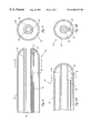
- FIG. 6A illustrates yet another embodiment of the catheter
- FIG. 6B is a sectional view of the catheter of FIG. 6A taken along line 6 B— 6 B;
- FIG. 7 illustrates another embodiment of an injection tube for use with the catheter of the present invention.
- FIG. 8 illustrates an exemplary tip structure for use with the catheter of the present invention
- FIG. 9 illustrates another embodiment of the catheter of the present invention.
- FIG. 10 illustrates another embodiment of the injection tube construction for use with the catheter of the present invention.
- FIG. 11 illustrates a spooling mechanism for use with the catheter of the present invention
- FIG. 12 is a detailed view of portion A of FIG. 11;
- FIG. 13 is a side view of the spool of FIG. 11;
- FIG. 14 illustrates yet another embodiment of the injection tube construction for use with the catheter of the present invention
- FIG. 15 illustrates still yet another embodiment of the injection tube construction for use with the catheter of the present invention
- FIG. 16 illustrates another embodiment of the catheter of the present invention
- FIG. 17A illustrates the catheter of FIG. 16 in a first configuration
- FIG. 17B illustrates the catheter of FIG. 16 in a second configuration.
- surgical device is intended to encompass any surgical implement used in association with human or animal medical treatment, diagnosis, study, or analysis. More particularly, a surgical device is intended to encompass any implement or portion thereof that is entirely or partially inserted into a human or animal body by any means of entry, such as through a natural body orifice, an incision, or a puncture.
- the term surgical device is not intended to connote a limitation to treatment of a single body system, organ, or site.
- the surgical device can be rigid as a thick steel pipe, completely flexible and pliant like a thread, or have a flexibility between the two extremes.
- the surgical device can have a diameter that ranges from inches to microns.
- the surgical device or catheter 10 includes an elongate outer member 12 having a flexible injection tube 14 disposed within the outer member 12 .
- the injection tube 14 defines a primary fluid path within the outer member 12 .
- a “fluid path” as used herein is intended to encompass an boundary, channel or guide through which a fluid can travel. It can include concentrically disposed catheters, multi lumen catheters, or a single loop of tubing within a sheath.
- fluid is intended to encompass materials in a liquid state, a gas state, or in a transition state between liquid and gas, and liquid and solid.
- the fluid can be a “cryogenic fluid” capable of reaching or creating extremely cold temperatures well below the freezing point of water; a “cooling fluid” that does not reach or create temperatures below the freezing point of water; a fluid capable of transferring heat away from a relatively warmer structure or body tissue; a fluid capable of transferring heat to a relatively cooler structure or body tissue; a fluid at or capable of creating a temperature between the freezing and boiling points of water; and a fluid at or capable of reaching or creating a temperature above the boiling point of water.
- the injection tube 14 of the present invention is adapted for slidable movement to a variety of positions within the outer member 12 .
- the injection tube 14 includes at least one opening 16 proximate a distal end of the injection tube.
- cryogenic fluid 18 is expelled from the opening 16 and returns to a proximal end of the catheter along a fluid path defined by an inner wall 30 of the outer member 12 .
- the injection tube 14 allows for greater aggregate cooling power as well as the creation of a variety of different cooling/freeze zones along the length of the outer member 12 .
- the injection tube 14 is located at a first position proximate the tip or distal end 22 of the outer member 12 .
- the catheter forms an iceball 20 which is located proximate and surrounds the distal end 22 of the outer member 12 .
- the injection tube 14 is slidable in a direction indicated by arrow 24 in FIG. 1 to an intermediary position which is a predetermined distance away from the first position shown in FIG. 1 .
- the catheter forms the iceball 20 which now has moved away from the distal end 22 of the outer member 12 .
- the injection tube 14 may then be moved in a direction indicated by arrow 26 to a second position as shown in FIG. 3 . In this second position, the ice ball 20 has moved even further away from the distal end 22 of the outer member 12 .
- the injection tube may be adjustably positionable at any number of intermediary positions between the first and second positions. Furthermore, the injection tube may also be moved back and forth between the first and second positions, such as in the direction indicated by arrow 28 in FIG. 3, depending on the desired cooling pattern.
- the flow of cooling fluid along the fluid path through the injection tube can be combined with movement of the injection tube in any number of patterns to provide a desired cooling pattern such as a discontinuous or a continuous ice ball or lesion across the catheter.
- the catheter would have a tip between about 2-6 Fr in diameter. It is contemplated that lesions up to 20 cm in length may be frozen using the devices described herein.
- the cross sectional dimensions of the catheter effectively limits the amount of refrigerant vapor that can be evacuated from the catheter tip region.
- an iceball would be formed at the tip of the catheter and then the injection tube would be slowly pulled back. This movement of the injection tube causes the iceball to also move “backwards” or in a direction towards the proximal end of the catheter.
- the fluid provided to the injection tube could be shut off at any time to allow the iceball to melt and to re-establish blood flow to the vessel if needed to prevent ischemia in the patient.
- This construction allows the user to return to treating of the vessel without having to reposition the catheter.
- This adjustable position injection tube of the present invention is also adaptable for situations where the user would like to freeze, at a given temperature, an area that is larger (longer) than the physical dimensions of the catheter allow.
- the injection tube may be made out of polyimide but it could be other high strength polymers and it could be metal, such as a stainless steel.
- coaxial just means that the tubes share a common axis.
- the catheter 50 includes an outer member 52 which has a cantilevered type guiding sheath 54 disposed therein.
- the sheath 54 includes a main guidewire lumen 55 and an injection tube lumen portion 56 which defines an internal lumen 57 which terminates in an end plug 59 .
- An injection tube 58 is slidably disposed within the internal lumen 57 of the injection tube lumen portion 56 .
- the catheter 60 includes an outer member 62 which has a cantilevered type guiding sheath 64 disposed therein.
- the sheath 64 includes a main guidewire lumen 65 and an injection tube lumen portion 66 .
- An injection tube 68 is slidably disposed within the injection tube lumen portion 66 .
- the entire injection lumen guide would be cut from the dual lumen (guidewire and injection lumen guide) in the tip region of the catheter.
- a guidewire lumen will run through the catheter tip. In this embodiment of the present invention this lumen will not run the length of the catheter.
- the injection tube 74 is provided with an angled tip 76 which is adapted for directional spraying.
- the tip may be formed at an angle ⁇ in the range of about 20 to 70 degrees and preferably 30 to 45 degrees.
- the entire injection lumen guide may be cut from the dual lumen (guidewire and injection lumen guide) in the tip region of the catheter.
- the tubing is skived so that there is more than 180 degrees of material left for the injection tube to slide within without falling out.
- a guidewire lumen will run through the catheter tip. In this exemplary embodiment, this lumen will not run the length of the catheter. Additionally, there will also be at least one thermocouple wire in this embodiment of the catheter.
- the guidewire lumen is glued into a catheter tip 78 , an embodiment of which is shown in FIG. 8 .
- thermocouples may be disposed along the external surface of the catheter. These thermocouples can be integrated with an internal feedback loop to provide confirmation and independent regulation of the temperature along the region affected by the adjustable injection tubes output.
- the catheter 80 includes an outer member 82 which has a rounded tip 84 at one end thereof.
- the catheter 80 includes an injection tube 86 which is coupled to a plug member 88 .
- the plug member 88 may be glued onto the injection tube 86 or otherwise attached by a friction or interference type fit with the injection tube 86 .
- the plug member 88 is further attached to a wire member 90 which is wound about a pulley member 92 .
- the wire member 90 may be soldered or otherwise similarly fixedly attached to the plug member 88 to avoid unwanted detachment of the wire member 90 from the plug member 88 .
- the wire member may be a single strand or a braided type wire sufficient to withstand the forces exerted on the wire in the catheter.
- the wire is of a metallic material and in an exemplary embodiment, has a diameter between about 0.008′′ to 0.020′′.
- the pulley member 92 is positioned proximate the distal end of the catheter 80 , preferably near the tip 84 .
- the pulley member 92 may be a non-rotating rod member.
- the injection tube 86 may be slidably positioned within the outer member 82 by pulling the wire member 90 in a first direction shown by arrow 94 .
- the injection tube 100 includes a plug member 102 and an attachment tube 104 which are fixedly attached to a distal end of the injection tube 100 .
- the plug member 102 has an internal lumen 108 formed therein which is in communication with the internal lumen 110 of the injection tube 100 . Cryogenic fluid expelled from the injection tube 100 may then exit through the plug member 102 through the plug lumen 108 .
- the plug member 102 is attached to a wire member 106 which provides for slidable movement of the injection tube in the catheter as described above.
- a spooling mechanism 120 for providing movement of the injection tube within a catheter is shown.
- the spooling mechanism 120 may be disposed within a handle portion, not shown, of the catheter.
- the spooling mechanism 120 includes an injection port coupling 122 , a tube coupling which includes a fixed segment 124 and a rotating segment 125 , a first spool 126 , a second spool 128 and a spool turning handle 130 .
- the injection port coupling 122 is connected to the tube coupled via a fixed tube 132 which is further connected to the injection tube 134 .
- the injection tube 134 is connected to a wire 138 which provides for slidable movement of the injection tube within the catheter as described later herein.
- a seal 136 may be provided to prevent leakage of any fluid within the catheter.
- a vacuum may also be provided via port 140 .
- FIG. 12 A more detailed view of the tube coupling is shown with reference to FIG. 12 .
- the fixed tube 132 is connected to the fixed segment 124 of the tube coupling to prevent the fixed tube from twisting thereby adversely affecting the performance of the catheter.
- the fixed segment 124 is in cooperation with the rotating segment 125 to provide for a connection to the first spool 126 which enables the injection tube within the catheter to be moved back and forth within the catheter.
- the injection tube 134 winds about the spool 126 to either retract the injection tube when spooled in one direction or to propel the injection forward within the catheter.
- a distal end of the injection tube is brought closer to the tip of the catheter.
- the distal end of the injection tube is pulled away from the tip of the catheter.
- these directions may be reversed to form iceball as desired.
- the spooling mechanism may be rotated back and forth in both directions or solely in one direction as demanded by the application.
- FIG. 14 A further embodiment of a construction of the catheter of the present invention is shown in FIG. 14 .
- the catheter 150 includes an injection tube 152 which is coupled to an attachment member 154 .
- At an opposite end of the attachment member 154 is a plug member 156 .
- the attachment member 154 has one or more hole or openings 158 formed thereon.
- a plurality of openings 158 may be used to create long uniform iceballs along the area to be treated.
- the attachment member 154 has a diameter which is larger than the diameter of the injection tube 152 such that a desirable resistance to flow is created in the catheter via the differential in diameters.
- the larger attachment tube 154 also allows larger openings 158 to be created in the catheter to achieve desired iceball patterns.
- the catheter 160 includes an injection tube 162 which is coupled to a reservoir member 164 which has a plug member 166 attached at an opposite end thereof.
- the plug member 166 has at least one or more openings 168 formed thereon, wherein when cryogenic fluid 172 is expelled from a distal end 174 of the injection tube and into the reservoir member 164 , the fluid may exit via the openings 168 in the plug member 166 .
- the plug member 166 may have a pull wire 170 attached at a distal end thereof to provide for slidable movement of the injection tube 162 within the catheter.
- the pull wire may have one or more strands attached to the plug member and in an exemplary embodiment as shown in FIG. 15, the two strands are merged at a proximal end of the catheter. Alternatively, the pull wires may be attached directly to the reservoir member 164 or even the injection tube 162 .
- the injection tube 162 is shown fixed within a reservoir member 164 .
- the proximal end 176 of the plug tube member 166 is moved in a first direction towards a distal end 174 of the injection tube 162 and when the pressure inside the reservoir member is increased, the proximal end 176 of the plug tube member 166 is moved in a second direction, away from the proximal end 174 of the injection tube 162 .
- the wires 170 prevent unwanted disengagement of the plug tube member 166 .
- the plug tube member 166 has a plurality of openings 168 formed therein.
- a discussion of an exemplary operation of the catheter of the present invention now follows.
- a predetermined amount of refrigerant is introduced into the catheter system which is controlled by pressurization of the liquid refrigerant at a control console.
- a given amount of flow will be achieved under a given pressure condition.
- the refrigerant expands.
- the temperature of the expanded gas is determined by the ambient pressure at the point of expansion.
- the region where gas expansion occurs is kept under negative gauge pressure (vacuum) by attaching a vacuum line to the catheter.
- the pressure differential between the vacuum source (the other end of the vacuum line) and the tip of the catheter (where expansion occurs) is determined by the flow that is occurring and the conditions between the tip of the catheter and the vacuum source (the resistance to the flow).
- the present invention allows cooling of the cylinders without the need to reposition the catheter for the cooling to a given temperature of a longer segment than was previously possible with a fixed injection tube system.
- the same length of cooling segment will be cooled as was cooled with a fixed injection tube but by movement of the injection tube, the iceball can be transitioned both forwards and backwards.
- Repositioning a shorter tipped catheter will not effectively accomplish the results as described above since in electrophysiology, placement of the tip of the catheter is very critical. For example, when the ice ball is formed, there is adhesion to the heart surface by the iceball. A moving ice ball allows contact to be maintained with the surface of the heart and thus no repositioning of the catheter would be necessary. Repositioning would be required if a shorter catheter was engaged in multiple applications.
- An added benefit of the present invention is that a smaller ice ball can be formed. Instead of creating the longest ice ball possible and moving it (or keeping it fixed if it was long enough) a shorter ice ball could be created and moved along the vessel.
- the smaller ice ball is useful in the coronary arteries where the iceball occludes the vessel. If the patient starts to experience chest pain (ischemic) due to the lack of flow to that region of their heart, the physician will want to cease treatment immediately in order to re-establish blood flow.
- a shorter ice ball as produced by the catheter of the present invention will also melt quicker thus re-establishing critical blood flow in a shorter amount of time.
- catheter of the present invention may be used to freeze segments of up to 20 cm long.
- catheter tips will range from about 3 Fr (0.039) in the coronaries to about 5 F (0.065) diameter in the femoral arteries.
- the catheter tip would range from about 7 F (0.092) to 9 F (0.118) in diameter.
- the catheter 200 includes an injection tube 202 which feeds into a distribute spray system.
- the catheter includes an underlying tube shuttle member 204 , which preferably is teflon lined and creates a shuttle which rides over the outside of a guidewire lumen 206 .
- the shuttle 204 is attached to a disk 208 at one end and at the other end of the disk is attached a nitinol wire 210 shaped in the form of a spring.
- the other end of the nitinol wire 210 is attached to the catheter tip 216 .
- a pull wire 212 is also attached to the shuttle and runs the length of the catheter to the handle, not shown.
- a spray tube 218 may also be attached to the shuttle 204 .
- the nitinol spring 210 relaxes and the pull wire 212 can be used to move the shuttle 204 longitudinally along the catheter.
- the pull wire 212 can be used to move the shuttle 204 longitudinally along the catheter.
- the catheter tip 216 warms to body temperature and the pull wire 212 is released, the nitinol wire 210 will take the spring shape again, and it will pull the shuttle forward to the start position, proximal the catheter tip 216 , as shown in FIG. 17 B.
Abstract
Description
Claims (8)
Priority Applications (1)
| Application Number | Priority Date | Filing Date | Title |
|---|---|---|---|
| US09/352,021 US6280439B1 (en) | 1999-07-12 | 1999-07-12 | Adjustable position injection tubing |
Applications Claiming Priority (1)
| Application Number | Priority Date | Filing Date | Title |
|---|---|---|---|
| US09/352,021 US6280439B1 (en) | 1999-07-12 | 1999-07-12 | Adjustable position injection tubing |
Publications (1)
| Publication Number | Publication Date |
|---|---|
| US6280439B1 true US6280439B1 (en) | 2001-08-28 |
Family
ID=23383465
Family Applications (1)
| Application Number | Title | Priority Date | Filing Date |
|---|---|---|---|
| US09/352,021 Expired - Lifetime US6280439B1 (en) | 1999-07-12 | 1999-07-12 | Adjustable position injection tubing |
Country Status (1)
| Country | Link |
|---|---|
| US (1) | US6280439B1 (en) |
Cited By (35)
| Publication number | Priority date | Publication date | Assignee | Title |
|---|---|---|---|---|
| US6497703B1 (en) * | 2000-03-02 | 2002-12-24 | Biosense Webster | Cryoablation catheter for long lesion ablations |
| EP1306059A2 (en) * | 2001-10-23 | 2003-05-02 | Biosense Webster, Inc. | Cryoablation catheter for long lesion ablations |
| US6579287B2 (en) | 2001-10-09 | 2003-06-17 | Cryocath Technologies Inc. | Cryosurgical ablation device having sequential injection and method therefor |
| US20030220634A1 (en) * | 2000-08-09 | 2003-11-27 | Ryba Eric L. | Refrigeration source for a cryoablation catheter |
| US20040024392A1 (en) * | 2002-08-05 | 2004-02-05 | Lewis James D. | Apparatus and method for cryosurgery |
| US20040034345A1 (en) * | 2002-08-16 | 2004-02-19 | Lentz David J. | Heat transfer segment for a cryoablation catheter |
| US20040034344A1 (en) * | 2002-08-16 | 2004-02-19 | Eric Ryba | Tip pressure monitoring for cryoablation catheters |
| EP1430849A1 (en) * | 2002-12-11 | 2004-06-23 | Cryocor, Inc. | Coaxial catheter system for performing a single step cryoablation |
| US6755823B2 (en) * | 2001-02-28 | 2004-06-29 | Cryocath Technologies Inc. | Medical device with enhanced cooling power |
| US20040215177A1 (en) * | 2003-04-24 | 2004-10-28 | Scimed Life Systems, Inc. | Therapeutic apparatus having insulated region at the insertion area |
| US20050016188A1 (en) * | 2003-07-24 | 2005-01-27 | Lentz David J. | Distal end for cryoablation catheters |
| US20050027289A1 (en) * | 2003-07-31 | 2005-02-03 | Thomas Castellano | Cryoablation systems and methods |
| US20050043724A1 (en) * | 2003-08-22 | 2005-02-24 | Eric Ryba | Reshapeable tip for a cryoprobe |
| US20050177146A1 (en) * | 2004-02-10 | 2005-08-11 | Marshall Sherman | System and method for assessing ice ball formation during a cryoablation procedure |
| US20050198972A1 (en) * | 2004-03-10 | 2005-09-15 | Lentz David J. | Pressure-temperature control for a cryoablation catheter system |
| US20050288657A1 (en) * | 2004-06-29 | 2005-12-29 | Lentz David J | Pressure monitor for cryoablation catheter |
| US20060004349A1 (en) * | 2004-06-30 | 2006-01-05 | Eric Ryba | System for detecting leaks and occlusions in a cryoablation catheter |
| US20060004350A1 (en) * | 2004-06-30 | 2006-01-05 | Eric Ryba | System and method for varying return pressure to control tip temperature of a cryoablation catheter |
| US20070088217A1 (en) * | 2005-10-13 | 2007-04-19 | Babaev Eilaz P | Apparatus and methods for the selective removal of tissue using combinations of ultrasonic energy and cryogenic energy |
| US20070233054A1 (en) * | 2005-10-13 | 2007-10-04 | Bacoustics, Llc | Apparatus and methods for the selective removal of tissue |
| US20090264876A1 (en) * | 2006-07-28 | 2009-10-22 | Centre Hospitalier Universitaire De Quebec | Probe, sleeve, system, method and kit for performing percutaneous thermotherapy |
| US20090281533A1 (en) * | 2008-05-12 | 2009-11-12 | Boston Scientific Scimed, Inc. | Apparatus and method for chilling cryo-ablation coolant and resulting cryo-ablation system |
| US20090287202A1 (en) * | 2008-05-15 | 2009-11-19 | Boston Scientific Scimed, Inc. | Apparatus and methods for cryogenically ablating tissue and adjusting cryogenic ablation regions |
| US20090299235A1 (en) * | 2008-06-03 | 2009-12-03 | Eilaz Babaev | Ultrasonic Endometrial Cryoablation Device |
| CN101803947A (en) * | 2010-03-11 | 2010-08-18 | 中国科学院理化技术研究所 | Cold and hot probe device used for cold and hot combination therapy of tumor |
| US20120089211A1 (en) * | 2010-04-08 | 2012-04-12 | Myoscience, Inc. | Methods and apparatus for cryogenically treating multiple tissue sites with a single puncture |
| US20130023914A1 (en) * | 2011-07-18 | 2013-01-24 | Clearear, Inc. | System for accessing body orifice and method |
| US20140074081A1 (en) * | 2011-02-01 | 2014-03-13 | Channel Medsystems, Inc. | Cyrogenic treatment systems |
| US9895183B2 (en) | 2013-09-17 | 2018-02-20 | Channel Medsystems, Inc. | Liner for cryogenic treatment systems |
| US10004551B2 (en) | 2009-06-01 | 2018-06-26 | Channel Medsystems, Inc. | Methods and apparatus for treatment of a body cavity or lumen |
| US10492844B2 (en) | 2017-05-25 | 2019-12-03 | Channel Medsystems, Inc. | Tethered system for cryogenic treatment |
| US10610279B2 (en) | 2014-04-10 | 2020-04-07 | Channel Medsystems, Inc. | Apparatus and methods for regulating cryogenic treatment |
| US20200345403A1 (en) * | 2019-05-03 | 2020-11-05 | The Board Of Trustees Of The Leland Stanford Junior University | Instruments and methodology involving cryoablation |
| US20210213298A1 (en) * | 2018-06-29 | 2021-07-15 | Sekisui Chemical Co., Ltd. | Plasma application apparatus |
| US11504178B2 (en) | 2015-10-08 | 2022-11-22 | Channel Medsystems, Inc. | Exhaust collection bag for cryogenic treatment |
Citations (18)
| Publication number | Priority date | Publication date | Assignee | Title |
|---|---|---|---|---|
| US3266492A (en) | 1963-09-06 | 1966-08-16 | Samuel B Steinberg | Cryosurgery probe device |
| SU628903A1 (en) * | 1976-04-26 | 1978-10-25 | Предприятие П/Я В-8117 | Apparatus for exerting localised cryogenic action upon biologic tissues |
| US4207897A (en) | 1976-07-21 | 1980-06-17 | Spembly Limited | Cryosurgical probe |
| GB2094636A (en) * | 1981-03-12 | 1982-09-22 | Spembly Ltd | A cryosurgical probe |
| SU1153901A1 (en) * | 1982-12-20 | 1985-05-07 | Физико-технический институт низких температур АН УССР | Cryodestructor for orientated freezing of tissue |
| US5078713A (en) | 1988-12-01 | 1992-01-07 | Spembly Medical Limited | Cryosurgical probe |
| US5108390A (en) | 1988-11-14 | 1992-04-28 | Frigitronics, Inc. | Flexible cryoprobe |
| JPH05168646A (en) * | 1991-12-20 | 1993-07-02 | Inter Noba Kk | Cryoabrasion device |
| US5423807A (en) | 1992-04-16 | 1995-06-13 | Implemed, Inc. | Cryogenic mapping and ablation catheter |
| US5716353A (en) | 1996-05-03 | 1998-02-10 | Urds, Corp. | Cryosurgical instrument |
| US5755690A (en) | 1987-01-09 | 1998-05-26 | C. R. Bard | Multiple layer high strength balloon for dilatation catheter |
| US5759182A (en) | 1993-11-09 | 1998-06-02 | Spembly Medical Limited | Cryosurgical probe with pre-cooling feature |
| US5800487A (en) | 1996-07-23 | 1998-09-01 | Endocare, Inc. | Cryoprobe |
| US5800486A (en) | 1996-06-17 | 1998-09-01 | Urologix, Inc. | Device for transurethral thermal therapy with cooling balloon |
| US5807391A (en) | 1993-10-26 | 1998-09-15 | Cordis Corporation | Cryo-ablation catheter |
| US5833685A (en) | 1994-03-15 | 1998-11-10 | Tortal; Proserfina R. | Cryosurgical technique and devices |
| US5846235A (en) | 1997-04-14 | 1998-12-08 | Johns Hopkins University | Endoscopic cryospray device |
| US5868735A (en) | 1997-03-06 | 1999-02-09 | Scimed Life Systems, Inc. | Cryoplasty device and method |
-
1999
- 1999-07-12 US US09/352,021 patent/US6280439B1/en not_active Expired - Lifetime
Patent Citations (18)
| Publication number | Priority date | Publication date | Assignee | Title |
|---|---|---|---|---|
| US3266492A (en) | 1963-09-06 | 1966-08-16 | Samuel B Steinberg | Cryosurgery probe device |
| SU628903A1 (en) * | 1976-04-26 | 1978-10-25 | Предприятие П/Я В-8117 | Apparatus for exerting localised cryogenic action upon biologic tissues |
| US4207897A (en) | 1976-07-21 | 1980-06-17 | Spembly Limited | Cryosurgical probe |
| GB2094636A (en) * | 1981-03-12 | 1982-09-22 | Spembly Ltd | A cryosurgical probe |
| SU1153901A1 (en) * | 1982-12-20 | 1985-05-07 | Физико-технический институт низких температур АН УССР | Cryodestructor for orientated freezing of tissue |
| US5755690A (en) | 1987-01-09 | 1998-05-26 | C. R. Bard | Multiple layer high strength balloon for dilatation catheter |
| US5108390A (en) | 1988-11-14 | 1992-04-28 | Frigitronics, Inc. | Flexible cryoprobe |
| US5078713A (en) | 1988-12-01 | 1992-01-07 | Spembly Medical Limited | Cryosurgical probe |
| JPH05168646A (en) * | 1991-12-20 | 1993-07-02 | Inter Noba Kk | Cryoabrasion device |
| US5423807A (en) | 1992-04-16 | 1995-06-13 | Implemed, Inc. | Cryogenic mapping and ablation catheter |
| US5807391A (en) | 1993-10-26 | 1998-09-15 | Cordis Corporation | Cryo-ablation catheter |
| US5759182A (en) | 1993-11-09 | 1998-06-02 | Spembly Medical Limited | Cryosurgical probe with pre-cooling feature |
| US5833685A (en) | 1994-03-15 | 1998-11-10 | Tortal; Proserfina R. | Cryosurgical technique and devices |
| US5716353A (en) | 1996-05-03 | 1998-02-10 | Urds, Corp. | Cryosurgical instrument |
| US5800486A (en) | 1996-06-17 | 1998-09-01 | Urologix, Inc. | Device for transurethral thermal therapy with cooling balloon |
| US5800487A (en) | 1996-07-23 | 1998-09-01 | Endocare, Inc. | Cryoprobe |
| US5868735A (en) | 1997-03-06 | 1999-02-09 | Scimed Life Systems, Inc. | Cryoplasty device and method |
| US5846235A (en) | 1997-04-14 | 1998-12-08 | Johns Hopkins University | Endoscopic cryospray device |
Cited By (82)
| Publication number | Priority date | Publication date | Assignee | Title |
|---|---|---|---|---|
| USRE40868E1 (en) * | 1999-06-25 | 2009-08-11 | Cryocor, Inc. | Refrigeration source for a cryoblation catheter |
| US6497703B1 (en) * | 2000-03-02 | 2002-12-24 | Biosense Webster | Cryoablation catheter for long lesion ablations |
| US20030220634A1 (en) * | 2000-08-09 | 2003-11-27 | Ryba Eric L. | Refrigeration source for a cryoablation catheter |
| US7004936B2 (en) | 2000-08-09 | 2006-02-28 | Cryocor, Inc. | Refrigeration source for a cryoablation catheter |
| US6755823B2 (en) * | 2001-02-28 | 2004-06-29 | Cryocath Technologies Inc. | Medical device with enhanced cooling power |
| US6579287B2 (en) | 2001-10-09 | 2003-06-17 | Cryocath Technologies Inc. | Cryosurgical ablation device having sequential injection and method therefor |
| EP1306059A3 (en) * | 2001-10-23 | 2004-07-21 | Biosense Webster, Inc. | Cryoablation catheter for long lesion ablations |
| EP1306059A2 (en) * | 2001-10-23 | 2003-05-02 | Biosense Webster, Inc. | Cryoablation catheter for long lesion ablations |
| US20040024392A1 (en) * | 2002-08-05 | 2004-02-05 | Lewis James D. | Apparatus and method for cryosurgery |
| US20040034345A1 (en) * | 2002-08-16 | 2004-02-19 | Lentz David J. | Heat transfer segment for a cryoablation catheter |
| US6955673B2 (en) | 2002-08-16 | 2005-10-18 | Cryocor, Inc. | Heat transfer segment for a cryoablation catheter |
| US20040034344A1 (en) * | 2002-08-16 | 2004-02-19 | Eric Ryba | Tip pressure monitoring for cryoablation catheters |
| EP1430849A1 (en) * | 2002-12-11 | 2004-06-23 | Cryocor, Inc. | Coaxial catheter system for performing a single step cryoablation |
| US20040215177A1 (en) * | 2003-04-24 | 2004-10-28 | Scimed Life Systems, Inc. | Therapeutic apparatus having insulated region at the insertion area |
| US8870859B2 (en) | 2003-04-24 | 2014-10-28 | Boston Scientific Scimed, Inc. | Therapeutic apparatus having insulated region at the insertion area |
| US20060089630A1 (en) * | 2003-04-24 | 2006-04-27 | Swanson David K | Therapeutic apparatus having insulated region at the insertion area |
| US20060089631A1 (en) * | 2003-04-24 | 2006-04-27 | Swanson David K | Therapeutic apparatus having insulated region at the insertion area |
| US8535305B2 (en) | 2003-04-24 | 2013-09-17 | Boston Scientific Scimed, Inc. | Therapeutic apparatus having insulated region at the insertion area |
| US7306590B2 (en) | 2003-04-24 | 2007-12-11 | Boston Scientific Scimed, Inc. | Therapeutic apparatus having insulated region at the insertion area |
| US20080215042A1 (en) * | 2003-04-24 | 2008-09-04 | Swanson David K | Therapeutic Apparatus Having Insulated Region At The Insertion Area |
| US7306589B2 (en) | 2003-04-24 | 2007-12-11 | Boston Scientific Scimed, Inc. | Therapeutic apparatus having insulated region at the insertion area |
| US6981382B2 (en) | 2003-07-24 | 2006-01-03 | Cryocor, Inc. | Distal end for cryoablation catheters |
| US20050016188A1 (en) * | 2003-07-24 | 2005-01-27 | Lentz David J. | Distal end for cryoablation catheters |
| US20050027289A1 (en) * | 2003-07-31 | 2005-02-03 | Thomas Castellano | Cryoablation systems and methods |
| US20050043724A1 (en) * | 2003-08-22 | 2005-02-24 | Eric Ryba | Reshapeable tip for a cryoprobe |
| US7104984B2 (en) | 2003-08-22 | 2006-09-12 | Cryocor, Inc. | Reshapeable tip for a cryoprobe |
| US7070594B2 (en) | 2004-02-10 | 2006-07-04 | Cryocor, Inc. | System and method for assessing ice ball formation during a cryoablation procedure |
| US20050177146A1 (en) * | 2004-02-10 | 2005-08-11 | Marshall Sherman | System and method for assessing ice ball formation during a cryoablation procedure |
| US20050198972A1 (en) * | 2004-03-10 | 2005-09-15 | Lentz David J. | Pressure-temperature control for a cryoablation catheter system |
| US20050288657A1 (en) * | 2004-06-29 | 2005-12-29 | Lentz David J | Pressure monitor for cryoablation catheter |
| US7156840B2 (en) | 2004-06-29 | 2007-01-02 | Cryocor, Inc. | Pressure monitor for cryoablation catheter |
| US20060004349A1 (en) * | 2004-06-30 | 2006-01-05 | Eric Ryba | System for detecting leaks and occlusions in a cryoablation catheter |
| US7357797B2 (en) | 2004-06-30 | 2008-04-15 | Cryocor, Inc. | System and method for varying return pressure to control tip temperature of a cryoablation catheter |
| US20060004350A1 (en) * | 2004-06-30 | 2006-01-05 | Eric Ryba | System and method for varying return pressure to control tip temperature of a cryoablation catheter |
| US7163535B2 (en) | 2004-06-30 | 2007-01-16 | Cryocor, Inc. | System for detecting leaks and occlusions in a cryoablation catheter |
| US7842032B2 (en) * | 2005-10-13 | 2010-11-30 | Bacoustics, Llc | Apparatus and methods for the selective removal of tissue |
| US7572268B2 (en) * | 2005-10-13 | 2009-08-11 | Bacoustics, Llc | Apparatus and methods for the selective removal of tissue using combinations of ultrasonic energy and cryogenic energy |
| US20070233054A1 (en) * | 2005-10-13 | 2007-10-04 | Bacoustics, Llc | Apparatus and methods for the selective removal of tissue |
| US20070088217A1 (en) * | 2005-10-13 | 2007-04-19 | Babaev Eilaz P | Apparatus and methods for the selective removal of tissue using combinations of ultrasonic energy and cryogenic energy |
| US20090264876A1 (en) * | 2006-07-28 | 2009-10-22 | Centre Hospitalier Universitaire De Quebec | Probe, sleeve, system, method and kit for performing percutaneous thermotherapy |
| US8425502B2 (en) | 2006-07-28 | 2013-04-23 | Centre Hospitalier Universitaire de Québec | Probe, sleeve, system, method and kit for performing percutaneous thermotherapy |
| US20090281533A1 (en) * | 2008-05-12 | 2009-11-12 | Boston Scientific Scimed, Inc. | Apparatus and method for chilling cryo-ablation coolant and resulting cryo-ablation system |
| US9655668B2 (en) | 2008-05-12 | 2017-05-23 | Boston Scientific Scimed, Inc. | Apparatus and method for chilling cryo-ablation coolant and resulting cryo-ablation system |
| US9028445B2 (en) | 2008-05-12 | 2015-05-12 | Frank W. Ingle | Apparatus and method for chilling cryo-ablation coolant and resulting cryo-ablation system |
| EP2291132B1 (en) * | 2008-05-15 | 2015-09-23 | Boston Scientific Scimed, Inc. | Apparatus for cryogenically ablating tissue and adjusting cryogenic ablation regions |
| US10070910B2 (en) | 2008-05-15 | 2018-09-11 | Boston Scientific Scimed, Inc. | Apparatus and methods for cryogenically ablating tissue and adjusting cryogenic ablation regions |
| US8480663B2 (en) | 2008-05-15 | 2013-07-09 | Boston Scientific Scimed, Inc. | Apparatus and methods for cryogenically ablating tissue and adjusting cryogenic ablation regions |
| US20090287202A1 (en) * | 2008-05-15 | 2009-11-19 | Boston Scientific Scimed, Inc. | Apparatus and methods for cryogenically ablating tissue and adjusting cryogenic ablation regions |
| US20090299235A1 (en) * | 2008-06-03 | 2009-12-03 | Eilaz Babaev | Ultrasonic Endometrial Cryoablation Device |
| US10849673B2 (en) | 2009-06-01 | 2020-12-01 | Channel Medsystems, Inc. | Methods and apparatus for treatment of a body cavity or lumen |
| US10004551B2 (en) | 2009-06-01 | 2018-06-26 | Channel Medsystems, Inc. | Methods and apparatus for treatment of a body cavity or lumen |
| CN101803947A (en) * | 2010-03-11 | 2010-08-18 | 中国科学院理化技术研究所 | Cold and hot probe device used for cold and hot combination therapy of tumor |
| CN101803947B (en) * | 2010-03-11 | 2012-09-05 | 中国科学院理化技术研究所 | Cold and hot probe device used for cold and hot combination therapy of tumor |
| US20120089211A1 (en) * | 2010-04-08 | 2012-04-12 | Myoscience, Inc. | Methods and apparatus for cryogenically treating multiple tissue sites with a single puncture |
| US9486267B2 (en) | 2011-02-01 | 2016-11-08 | Channel Medsystems, Inc. | Cryogenic treatment systems |
| US9277952B2 (en) | 2011-02-01 | 2016-03-08 | Channel Medsystems, Inc. | Cryogenic treatment systems |
| US9445860B2 (en) | 2011-02-01 | 2016-09-20 | Channel Medsystems, Inc. | Handheld cyrogenic treatment systems |
| US8858543B2 (en) | 2011-02-01 | 2014-10-14 | Channel Medsystems, Inc. | Cyrogenic treatment systems |
| US9492218B2 (en) | 2011-02-01 | 2016-11-15 | Channel Medsystems, Inc. | Pressure monitoring systems |
| US9492217B2 (en) | 2011-02-01 | 2016-11-15 | Channel Medsystems, Inc. | Treatments using cryogenic ablation systems |
| US9498274B2 (en) | 2011-02-01 | 2016-11-22 | Channel Medsystems, Inc. | Liner extraction methods |
| US9510887B2 (en) | 2011-02-01 | 2016-12-06 | Channel Medsystems, Inc. | Time-limited methods for cryogenic treatment systems |
| US9517100B2 (en) | 2011-02-01 | 2016-12-13 | Channel Medsystems, Inc. | Cryogenic treatment methods |
| US9603650B2 (en) | 2011-02-01 | 2017-03-28 | Channel Medsystems, Inc. | Cryogenic treatment systems |
| US9283022B2 (en) | 2011-02-01 | 2016-03-15 | Channel Medsystems, Inc. | Methods and apparatus for cryogenic treatment of a body cavity or lumen |
| US9848933B2 (en) | 2011-02-01 | 2017-12-26 | Channel Medsystems, Inc. | Liner for cryogenic treatment systems |
| US11883324B2 (en) | 2011-02-01 | 2024-01-30 | Channel Medsystems, Inc. | Cryogenic treatment systems |
| US9408657B2 (en) * | 2011-02-01 | 2016-08-09 | Channel Medsystems, Inc. | Cryogenic treatment systems |
| US11833076B2 (en) | 2011-02-01 | 2023-12-05 | Channel Medsystems, Inc. | Methods and apparatus for cryogenic treatment of a body cavity or lumen |
| US10959879B2 (en) | 2011-02-01 | 2021-03-30 | Channel Medsystems, Inc. | Methods and apparatus for cryogenic treatment of a body cavity or lumen |
| US20140074081A1 (en) * | 2011-02-01 | 2014-03-13 | Channel Medsystems, Inc. | Cyrogenic treatment systems |
| US20130023914A1 (en) * | 2011-07-18 | 2013-01-24 | Clearear, Inc. | System for accessing body orifice and method |
| US10849672B2 (en) | 2013-09-17 | 2020-12-01 | Channel Medsystems, Inc. | Liner for cryogenic treatment systems |
| US11607263B2 (en) | 2013-09-17 | 2023-03-21 | Channel Medsystems, Inc. | Liner for cryogenic treatment systems |
| US9895183B2 (en) | 2013-09-17 | 2018-02-20 | Channel Medsystems, Inc. | Liner for cryogenic treatment systems |
| US10610279B2 (en) | 2014-04-10 | 2020-04-07 | Channel Medsystems, Inc. | Apparatus and methods for regulating cryogenic treatment |
| US11793561B2 (en) | 2014-04-10 | 2023-10-24 | Channel Medsystems, Inc. | Apparatus and methods for regulating cryogenic treatment |
| US11504178B2 (en) | 2015-10-08 | 2022-11-22 | Channel Medsystems, Inc. | Exhaust collection bag for cryogenic treatment |
| US10492844B2 (en) | 2017-05-25 | 2019-12-03 | Channel Medsystems, Inc. | Tethered system for cryogenic treatment |
| US11678926B2 (en) | 2017-05-25 | 2023-06-20 | Channel Medsystems, Inc. | Tethered system for cryogenic treatment |
| US20210213298A1 (en) * | 2018-06-29 | 2021-07-15 | Sekisui Chemical Co., Ltd. | Plasma application apparatus |
| US20200345403A1 (en) * | 2019-05-03 | 2020-11-05 | The Board Of Trustees Of The Leland Stanford Junior University | Instruments and methodology involving cryoablation |
Similar Documents
| Publication | Publication Date | Title |
|---|---|---|
| US6280439B1 (en) | Adjustable position injection tubing | |
| US6913604B2 (en) | Cryosurgical catheter | |
| US9861423B2 (en) | Balloon design to enhance cooling uniformity | |
| US6551309B1 (en) | Dual action cryoprobe and methods of using the same | |
| US6575933B1 (en) | Mechanical support for an expandable membrane | |
| US8585690B2 (en) | Cryosurgical catheter | |
| US8986293B2 (en) | Cryoballoon refrigerant dispersion control | |
| US6899709B2 (en) | Coolant injection | |
| CN101868188B (en) | Flexible multi-tubular cryoprobe | |
| JP4833494B2 (en) | Cryotherapy apparatus and method | |
| US6235019B1 (en) | Cryosurgical catheter | |
| US20040158237A1 (en) | Multi-energy ablation station | |
| JP2009522037A5 (en) | ||
| US20090069876A1 (en) | System and Method for thermally Treating Tissues | |
| US9168079B2 (en) | Method and system to prevent complete obstruction in catheter in case of a kink | |
| JP2006524101A (en) | Treatment device having a region isolated by an insertion region | |
| KR20050012131A (en) | Distal end for cryoablation catheters | |
| EP1467668B1 (en) | Cryosurgical catheter | |
| EP1011489B1 (en) | Apparatus for linear ablation | |
| US20230063557A1 (en) | Multi-lumen cryogenic probe | |
| EP1135077B1 (en) | Cryosurgical catheter | |
| KR20200085155A (en) | Cryoablation catheter for hypertrophic cardiomyopahty and cryoablation for hypertrophic cardiomyopahty in use of it |
Legal Events
| Date | Code | Title | Description |
|---|---|---|---|
| AS | Assignment |
Owner name: CRYOCATH TECHNOLOGIES, INC., CANADA Free format text: ASSIGNMENT OF ASSIGNORS INTEREST;ASSIGNORS:MARTIN, ROBERT;LUECKGE, CLAUDIA;CAPUANO, LEA;AND OTHERS;REEL/FRAME:010102/0955 Effective date: 19990708 |
|
| STCF | Information on status: patent grant |
Free format text: PATENTED CASE |
|
| AS | Assignment |
Owner name: LA FINANCIERE DU QUEBEC, QUEBEC Free format text: SECURITY INTEREST;ASSIGNOR:CRYOCATH TECHNOLOGIES, INC.;REEL/FRAME:015035/0808 Effective date: 20040211 |
|
| REFU | Refund |
Free format text: REFUND - SURCHARGE, PETITION TO ACCEPT PYMT AFTER EXP, UNINTENTIONAL (ORIGINAL EVENT CODE: R2551); ENTITY STATUS OF PATENT OWNER: LARGE ENTITY |
|
| FPAY | Fee payment |
Year of fee payment: 4 |
|
| FEPP | Fee payment procedure |
Free format text: PAT HOLDER NO LONGER CLAIMS SMALL ENTITY STATUS, ENTITY STATUS SET TO UNDISCOUNTED (ORIGINAL EVENT CODE: STOL); ENTITY STATUS OF PATENT OWNER: LARGE ENTITY |
|
| FPAY | Fee payment |
Year of fee payment: 8 |
|
| AS | Assignment |
Owner name: CRYOCATH TECHNOLOGIES INC., CANADA Free format text: RELEASE BY SECURED PARTY;ASSIGNOR:INVESTISSEMENT QUEBEC;REEL/FRAME:022320/0787 Effective date: 20090220 Owner name: CRYOCATH TECHNOLOGIES INC.,CANADA Free format text: RELEASE BY SECURED PARTY;ASSIGNOR:INVESTISSEMENT QUEBEC;REEL/FRAME:022320/0787 Effective date: 20090220 |
|
| AS | Assignment |
Owner name: MEDTRONIC CRYOCATH LP, CANADA Free format text: ASSIGNMENT OF ASSIGNORS INTEREST;ASSIGNOR:CRYOCATH TECHNOLOGIES INC.;REEL/FRAME:023119/0651 Effective date: 20090814 Owner name: MEDTRONIC CRYOCATH LP,CANADA Free format text: ASSIGNMENT OF ASSIGNORS INTEREST;ASSIGNOR:CRYOCATH TECHNOLOGIES INC.;REEL/FRAME:023119/0651 Effective date: 20090814 |
|
| FPAY | Fee payment |
Year of fee payment: 12 |