US6283268B1 - Bezel for an automatic transaction machine - Google Patents
Bezel for an automatic transaction machine Download PDFInfo
- Publication number
- US6283268B1 US6283268B1 US09/194,504 US19450499A US6283268B1 US 6283268 B1 US6283268 B1 US 6283268B1 US 19450499 A US19450499 A US 19450499A US 6283268 B1 US6283268 B1 US 6283268B1
- Authority
- US
- United States
- Prior art keywords
- bezel
- payment
- aperture
- face
- accepting
- Prior art date
- Legal status (The legal status is an assumption and is not a legal conclusion. Google has not performed a legal analysis and makes no representation as to the accuracy of the status listed.)
- Expired - Lifetime
Links
- 239000012530 fluid Substances 0.000 claims description 7
- 239000007788 liquid Substances 0.000 claims description 6
- 238000003780 insertion Methods 0.000 description 3
- 230000037431 insertion Effects 0.000 description 3
- 238000010200 validation analysis Methods 0.000 description 3
- 238000000151 deposition Methods 0.000 description 2
- 238000000034 method Methods 0.000 description 2
- 238000012986 modification Methods 0.000 description 2
- 230000004048 modification Effects 0.000 description 2
- 229910000831 Steel Inorganic materials 0.000 description 1
- 229910052782 aluminium Inorganic materials 0.000 description 1
- XAGFODPZIPBFFR-UHFFFAOYSA-N aluminium Chemical compound [Al] XAGFODPZIPBFFR-UHFFFAOYSA-N 0.000 description 1
- 239000002131 composite material Substances 0.000 description 1
- 235000009508 confectionery Nutrition 0.000 description 1
- 238000013461 design Methods 0.000 description 1
- 230000000694 effects Effects 0.000 description 1
- 239000011521 glass Substances 0.000 description 1
- 238000004519 manufacturing process Methods 0.000 description 1
- 239000000463 material Substances 0.000 description 1
- 238000005259 measurement Methods 0.000 description 1
- 229910052751 metal Inorganic materials 0.000 description 1
- 239000002184 metal Substances 0.000 description 1
- 230000000717 retained effect Effects 0.000 description 1
- 239000010959 steel Substances 0.000 description 1
Images


Classifications
-
- G—PHYSICS
- G07—CHECKING-DEVICES
- G07F—COIN-FREED OR LIKE APPARATUS
- G07F9/00—Details other than those peculiar to special kinds or types of apparatus
- G07F9/02—Devices for alarm or indication, e.g. when empty; Advertising arrangements in coin-freed apparatus
-
- G—PHYSICS
- G07—CHECKING-DEVICES
- G07F—COIN-FREED OR LIKE APPARATUS
- G07F7/00—Mechanisms actuated by objects other than coins to free or to actuate vending, hiring, coin or paper currency dispensing or refunding apparatus
- G07F7/04—Mechanisms actuated by objects other than coins to free or to actuate vending, hiring, coin or paper currency dispensing or refunding apparatus by paper currency
-
- G—PHYSICS
- G07—CHECKING-DEVICES
- G07F—COIN-FREED OR LIKE APPARATUS
- G07F9/00—Details other than those peculiar to special kinds or types of apparatus
- G07F9/10—Casings or parts thereof, e.g. with means for heating or cooling
Definitions
- the invention relates generally to a bezel having at least one aperture to receive two or more forms of money, wherein the face of the bezel fits through an industry-standard size opening in the front panel of an automatic transaction machine.
- the opening formerly has been reserved for accommodating a bill validator only.
- a bezel according to the invention may have one or more apertures to accept banknotes and coins, or banknotes and credit cards, or some other combination. Consequently, a bill validator and a coin validator, or a bill validator and a card reader, or some other combination of money acceptance means connect to the rear of the bezel.
- Prior art candy vending machines typically accepted only coins as payment for a vend item.
- modern day vending machines and other automatic transaction systems may contain a coin slot for depositing coins, a bill entryway for inserting paper currency, and a card reader opening for inserting a debit or credit card.
- the new payment modes have been added to vending machines over time as vending items became more expensive, and as the technology for reliable bill validators and card readers developed.
- a bezel for each form of payment having an insertion slot or opening has been attached to the front panel of a vending machine.
- payment acceptance devices for coins, bills, tokens and cards each are connected to a bezel, and the three bezels are located on the right side of the front panel.
- This area is usually referred to as the control panel.
- new forms of payment acceptance devices have been retrofit to existing machines, it has become more difficult to attach them to the control panel because the amount of space available is finite, and because of internal component space restrictions.
- some vending machines have bezels with money insertion slots located in areas other than the control panel.
- one type of vending machine may differ from another by having bezels connected in different designated areas for payment, by accepting different forms of payment, and further may be marked in an entirely different manner. Since no standard configuration exists for accepting payment, consumers are often confused when it comes to the method and types of acceptable payments to enable a vend. Such non-uniformity may frustrate a customer, resulting in lost profits by the automatic transaction machine owners. Consequently, a need exists for a standard size bezel that can accommodate two or more money acceptance means.
- the invention concerns a bezel for attachment to the front panel of an automatic transaction machine having at least two apertures for accepting different forms of payment.
- the face of a bezel fits through an industry-standard size bill entryway opening in the front panel, and has two or more apertures for accepting money.
- a base plate connected to the face has connection means for attachment to the front panel or frame of a vending machine.
- a bill validator, a coin validator and/or a card reader may attach to the base plate of the bezel.
- the bezel may also contain a coin reject button. Consequently, a bezel according to the invention advantageously permits a consumer to quickly determine exactly what types of payment are acceptable to procure a vend item.
- a bezel for an automatic transaction machine such as a gaming machine, vending machine, pay telephone or the like, that has a face with one aperture for accepting at least two forms of payment.
- the face of the bezel fits through an industry-standard size opening in a panel of the automatic transaction machine.
- a bill validator, a coin validator, a card reader or other payment acceptance means may attach to the rear of the bezel, depending on transaction machine requirements.
- a base plate may be connected to the face for attachment to the front panel.
- the bezel permits the utilization of a single liquid diverting tray anti-fraud component because the apertures are clustered in one area, and in the case of the second embodiment there is only one aperture.
- the liquid diverting tray may be attached to the base plate, and functions to limit the damage that may occur from the introduction of fluids through the aperture or apertures.
- one or more connectors may be attached to the base plate on the rear of the bezel, for guiding the wires from the money acceptance means.
- a universal connector may be used to facilitate the connections of the money acceptance components.
- FIG. 1 is a front view of a prior art vending machine system that accepts multiple forms of payment
- FIG. 2 is an enlarged, cutaway side view of the vending machine system of FIG. 1;
- FIG. 3A is a front view of a bezel according to the present invention.
- FIG. 3B is a scaled-down front view of the bezel of FIG. 3A shown with a bill stacker and a coin validator;
- FIG. 4A is a front view of another embodiment of a bezel according to the present invention.
- FIG. 4B is a left-side perspective view of the bezel of FIG. 4A shown with attached bill validator, coin validator and card reader;
- FIG. 4C is a right side view of the bezel and attached components of FIG. 4B;
- FIG. 5A is a front view of the bezel of FIG. 4A shown connected to a tray;
- FIG. 5B is a side view of FIG. 5A
- FIG. 6 is a rear view of the bezel of FIG. 4A shown with connectors
- FIGS. 7A-7C are front views of three variations of another embodiment of a bezel according to the invention.
- FIGS. 8A-8C are front views of three variations of another embodiment of a bezel according to the invention.
- FIG. 9 is a front view of another embodiment of a bezel according to the invention.
- FIG. 1 is a front view of a prior art multiple payment vending machine system 1 which is capable of accepting a plurality of payment means in exchange for a product.
- the vending machine system 1 can accept coins, passive and smart tokens, banknotes or bills, smart cards, credit or debit cards and electronic purse devices.
- electronic purse device used herein denotes a token or card possessing an electronic circuit, a magnetic strip or other data storing medium or circuitry, for retaining a credit value equivalent to money.
- a vending machine system 1 is used as an example, the invention also applies to other automatic transaction systems, such as gaming machines, pay telephones and the like. It should also be understood that like components in the figures have been numbered the same throughout for ease of reference.
- a variety of products 10 to be dispensed are stored in a display area 15 inaccessible to customers, such as behind a transparent glass panel.
- Each product 10 is retained by a product delivery apparatus 20 that is selectively actuatable by a customer to dispense the product into a delivery area 30 from which the customer can retrieve the selected product.
- the front panel 35 of the vending machine system 1 has a control panel 40 having a coin slot 50 , a bill entryway 60 and a card opening 70 to accept payment for an item.
- the card opening 70 may accept an electronic purse device, credit card or debit card.
- the control panel 40 also contains a coin return 80 and an item selector such as a keypad 90 .
- a display 95 may provide instructions and information to a customer.
- a customer initiates a transaction by depositing coins or bills of particular denominations into respective openings 50 or 60 along the control panel 40 in payment for an item.
- a customer may also insert an electronic purse device, or a debit or credit card into card opening 70 to initiate a transaction.
- the customer may select a product 10 to be dispensed using keypad 90 .
- the corresponding product delivery apparatus 20 will then dispense the selected product 10 to the product delivery area 30 where it can be retrieved by the customer. Any change resulting from the transaction may be paid back to the customer through the coin return opening 80 or be credited by a card reader to an inserted electronic purse device. Details concerning money validation, card validation, establishing credit, dispensing products, paying out change, and other such vending machine or other automatic transaction machine functions are beyond the scope of this application and thus will not be discussed herein.
- FIG. 2 is an enlarged, cutaway side view along dotted line A—A of FIG. 1 which illustrates the layout of typical internal components of the vending machine.
- a bill validator 100 which is aligned with the bill entryway 60
- a coin mechanism 110 connected to the coin slot 50 via coin passageway 117
- a card reader 112 aligned with the card opening 70 .
- the coin mechanism 110 is also attached to the coin return 80 , and to a coin box 120 .
- the bill validator 100 is also attached to a bill stacker 105 .
- a keypad 90 and display 95 are also connected to the control panel 40 , and are electronically connected via lines 140 to a vending controller 130 .
- the card reader 112 , bill validator 100 and coin validator 110 are also electronically connected to the vending controller 130 .
- the connection of the payment devices shown in FIGS. 1 and 2 to the vending machine front panel 35 , and the electronic connections to the vending controller 130 are merely illustrative. Many other configurations may be used.
- the coin mechanism 110 may contain a microprocessor that supervises the activities of the bill validator 100 and the card reader 90 and that authorizes a vend, such that only total credit information is sent to the vending controller 130 .
- some or all of the money acceptance apertures may be located to the left of the product display area 15 and not in the control panel 40 , which affects the placement of the payment acceptance devices within the vending machine 1 .
- FIG. 3A is a front view of an embodiment of a bezel 150 according to the invention.
- the bezel 150 is preferably made of steel, aluminum, or other metal, but may also be comprised of a durable plastic, strong composite material or a combination of such materials.
- the face 151 of the bezel 150 is designed to fit into an industry-standard size bill entryway opening in a front panel of a vending machine that is typically reserved for connection of a bill validator only. Consequently, the face 151 of the bezel 150 has a width “A” of approximately 86.20 millimeters (3.394 inches), and a length “B” of approximately 108.70 millimeters (4.280 inches).
- the four cut-out connector portions labelled 102 A, 102 B, 102 C and 102 D are arranged about the base plate 103 of the bezel 150 to enable easy attachment to the control panel 40 , or to a frame component (not shown) internal to the vending machine.
- the width “A” between the centers of the cut-out portions 102 A and 102 B is approximately 86.20 millimeters (3.394 inches), and the width “C” between the centers of cut-out portions 102 C and 102 D is approximately 50.80 millimeters (2.0 inches).
- the length “D” between the centers of cut-out portions 102 A and 102 C is approximately 117.48 millimeters (4.625 inches).
- the reject button 55 need not be included in the face 151 of bezel 150 , and could be located elsewhere in the control panel 40 .
- opening 54 need not be provided in the bezel.
- a coin reject button is conventionally located adjacent to the coin slot for the convenience of the consumer.
- FIG. 3B is a scaled-down view of the bezel 150 of FIG. 3A illustrating the internal positions of a bill stacker 105 and a coin validator 110 in relation to the bezel 150 .
- a consumer would only view the bezel face 151 from her vantage point, which defines the transaction area for the vending machine.
- the bezel is also advantageously designed from the perspective of the vending machine owner because it permits the easy replacement of each payment module in the field.
- the bezel 150 enables all of the apertures leading into the vending machine to be clustered in one area, which can simplify the design of security features as discussed below.
- the invention simplifies vending machine manufacture since only one bezel need be mounted on the front panel instead of multiple bezels (one for each payment acceptance means).
- FIG. 4A is a front view of another embodiment of a bezel 200 according to the invention, having three money acceptance apertures, a card opening 70 , a bill entryway 60 and a coin slot 50 .
- a coin return button 55 is also shown, which is optional as explained above.
- the face 201 of the bezel 200 fits into the industry-standard bill entryway opening in a front panel of a vending machine. Consequently, the dimensions “A” and “B” of the face 201 are the same as those described above with respect to FIG. 3 A.
- the four cut-out portions 202 A, 202 D, 202 C and 202 D are arranged about the base plate 203 to permit easy attachment to the control panel 40 of a vending machine, and the dimensions defined by “A”, “C” and “D” are the same as those described above with respect to the bezel 150 of FIG. 3 A.
- FIG. 4B is a left-side perspective view of the bezel 200 of FIG. 4A connected to a bill validator 100 and associated bill stacker 105 , a coin validator 110 and a card reader 112 .
- the face 201 of the bezel 200 is sized to fit through an industry-standard size bill entryway opening in the control panel 40 of a vending machine.
- such a bezel could be made to fit other standard size openings, and to connect to other stud locations, of any particular type of automatic transaction machine.
- a consumer need only find the face 201 of the bezel 200 to locate the transaction area.
- the consumer may insert a bill into bill entryway 60 , or coins into coin slot 50 or a card into card opening 70 to pay for a transaction.
- the bill entryway 60 and coin return button 55 project outwardly from the face 201 of the bezel 200 .
- the coin slot 50 and the card opening 70 are flush with the face 201 of the bezel 200 .
- One of skill in the art could easily arrange for one or more of the other openings to project from the face of the bezel.
- the bezel could be manufactured such that all or some of the openings, and the coin return button 55 , are flush with the face.
- FIG. 4C is a right side view of the bezel 200 and components FIGS. 4A and 4B. It can be easily seen from FIG. 4C that the bill entryway 60 and coin return button 55 project from the face 201 of the bezel 200 , while the card opening 70 and coin slot 50 are flush therewith. Also shown in FIG. 4C, aligned with their respective openings in the bezel 200 , are a bill validator 100 and associated bill stacker 105 , a card reader 112 and a coin validator 110 . Regarding the coin validator 110 , a coin passageway 52 is aligned with the coin slot 50 to guide an inserted coin to a coin receiving cup 54 .
- a linkage 57 connects the coin return button 55 to the return switch 59 of the coin validator 110 , so that a coin will be returned after its insertion via return chute 58 when the coin return button 55 is pressed by a consumer.
- the coin return button 55 could be connected to the coin mechanism 110 via a remote switch and an electronic actuator to provide for the return of inserted coins.
- FIG. 5A illustrates the bezel 200 of FIGS. 4A-4C with an attached fluid diverting tray 300 fitted beneath the payment openings 50 , 60 and 70 .
- the fluid diverting tray 300 has connection means for attachment to the rear of the base plate 203 at cut out portions 202 C and 202 D.
- the tray 300 contains a drain 302 , and functions to protect the coin mechanism 110 and other interior vending machine components from a fluid attack.
- FIG. 5B is a side view of the bezel 200 and payment means configuration of FIG. 5 A.
- the fluid diverting tray 300 is shown positioned above the coin validator 110 and protects it by directing any injected fluids to drain 302 .
- FIG. 6 is a rear view of the bezel 200 of FIG. 4A illustrating the apertures in the base plate 203 in the absence of the money acceptance components.
- a bill validator opening 61 , coin slot 50 , coin return button opening 54 and card aperture 70 are shown.
- wire guides 300 , 301 and 304 , 305 are depicted.
- the wire guides 300 , 301 and 304 , 305 may be clips which are designed to hold, gather and/or guide the electrical wires from the various money acceptance components to facilitate their electrical connection and disconnection.
- Other types of wire harnessing devices could be used in alternate configurations depending on the money acceptance components used and their physical and electrical relationship to one another, which would be readily apparent to one of skill in the art.
- a universal connector integrated into the base plate could be used. The payment devices would all plug into the universal connector, which would simplify the electrical connections of the money acceptance means by eliminating all other cables except for one interface cable.
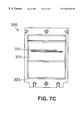
- FIG. 7A is a front view of another embodiment of a bezel 300 , having one payment acceptance aperture 310 for accepting both bills and coins.
- a consumer tenders bills in a horizontal orientation and coins in a vertical orientation into the aperture 310 .
- the bill and coin entryways are linked and overlap with each other.
- the corresponding acceptance means are attached from the interior of the automatic transaction machine, and the coin passageway and bill entryway intersect to the right side of the bezel as shown.
- the face 301 of the bezel fits into an industry-standard size opening through a panel of the automatic transaction machine, which size is determined by the type of machine and industry for which the bezel 300 is designed.
- the dimensions “Aa” and “Bb” may be different depending on, for example, if the bezel is for use with a gaming machine or for a pay telephone.
- the four cut-out portions 302 A, 302 B, 302 C and 302 D are arranged about the base plate 303 to permit easy attachment to the automatic transaction machine of choice, and the base plate and cut-out portions would be dimensioned accordingly.
- FIGS. 7B-7C and 8 A- 8 C illustrate alternate embodiments of a bezel having one aperture for accepting two or more forms of payment.
- Like components have been numbered the same for ease of reference.
- the face 301 and base plate 303 of FIGS. 7B-7C and 8 A- 8 C have the same dimensions as that of FIG. 7A in these examples.
- the dimensions of the face, base plate, and cut-out portions could be changed to match whatever size is required by a particular type of automatic transaction machine.
- the size of the aperture or apertures for accepting coins, bills, card, tokens and/or other payment means will be appropriate for accepting payment types normally accepted in the country or countries where the automatic transaction machine will be in use.
- the coin and bill openings of a bezel for use in the Mexican market will be a different size than that for use in the Canadian market.
- Such modifications are well within the capability of one skilled in the art.
- FIGS. 7B and 7C both illustrate a bezel 320 and 330 having one aperture 321 , 331 for accepting two forms of payment.
- the bezel 320 of FIG. 7B has an opening 321 that has overlapping coin and bill entryways for accenting coins and bills
- the bezel 330 has an opening 331 that has overlapping card and bill entryways for accepting cards and bills.
- the vertical coin entryway opening in FIG. 7B is biased toward the right side of the face 301 ; however, other locations along the length of the bill entryway could be used.
- the card entryway is shown above the bill entryway and biased to the left side of the face 301 in FIG. 7C, but it could be in other locations, such as below and in the center of the bill entrance.
- the card entryway could be positioned in a vertical orientation, like the coin entryway of FIG. 7B, if there is adequate room in the face 301 and if such an orientation is preferable.
- FIGS. 8A-8C illustrate alternate embodiments of a bezel having one aperture for accepting three forms of payment.
- each aperture 341 , 351 and 361 in each of the bezels 340 , 350 and 360 can accept coins or tokens, bills and cards.
- FIG. 9 illustrates a bezel 400 having one aperture 410 for accepting coins or tokens and bills, and a second aperture 411 for accepting cards. Both apertures 410 , 411 are located in the face 401 which fits through an opening in the panel of an automatic transaction machine.
- Other configurations of overlapping apertures for accepting other types of payment or for providing different combinations of payment types are readily apparent in view of the descriptions of FIGS. 7A-7C and 8 A- 8 C above.
- the invention enables a vending machine or other automatic transaction machine owner to provide one convenient location for accepting multiple forms of payment from a customer. Further, such a multiple payment area presents an attractive appearance.
- a bezel according to the invention gives a vending machine owner the freedom to easily utilize two or more forms of payment acceptance devices in one defined area without sacrificing front panel space which could be put to better use, for example, to advertise the products for sale.
- a liquid diverting tray can be attached beneath the aperture or apertures of the bezel to provide protection from liquid attacks.
- one or more connectors may be integrated into the base plate of the bezel to simplify the electrical connections of the money acceptance means.
- a bezel according to the invention has been shown in particular configurations, it should be understood that other combinations of money acceptance means in other configurations are contemplated. It is also to be understood that more than three openings could be utilized. Such alternate configurations may be necessary to accommodate various validation devices, to maximize consumer convenience, and/or to encourage one or more types of payment.
- Such a bezel may be manufactured after carefully considering the types of products to be sold in the automatic transaction machine. For example, if high-priced items are to be vended, then the bezel should contain a bill entryway and a card acceptance aperture or openings.
- one or more openings to accept coins and bills could be positioned in a way that encourages their use.
- One of skill in the art understands that the placement of the opening or openings in the bezel for accepting payment may be interchanged with one another, and also may be designed for accommodating other types of money acceptance means.
- connection openings 202 are shown on the base plate 203 to enable connection of the bezel 200 to a front panel of a vending machine, many other connection configurations could be used.
- connection openings 202 are shown on the base plate 203 to enable connection of the bezel 200 to a front panel of a vending machine, many other connection configurations could be used.
Abstract
Description
Claims (14)
Priority Applications (1)
| Application Number | Priority Date | Filing Date | Title |
|---|---|---|---|
| US09/194,504 US6283268B1 (en) | 1996-05-30 | 1997-05-27 | Bezel for an automatic transaction machine |
Applications Claiming Priority (3)
| Application Number | Priority Date | Filing Date | Title |
|---|---|---|---|
| US08/655,726 US5791449A (en) | 1996-05-30 | 1996-05-30 | Bezel for a vending machine |
| US09/194,504 US6283268B1 (en) | 1996-05-30 | 1997-05-27 | Bezel for an automatic transaction machine |
| PCT/US1997/009191 WO1997045813A1 (en) | 1996-05-30 | 1997-05-27 | Bezel for an automatic transaction machine |
Related Parent Applications (1)
| Application Number | Title | Priority Date | Filing Date |
|---|---|---|---|
| US08/655,726 Continuation-In-Part US5791449A (en) | 1996-05-30 | 1996-05-30 | Bezel for a vending machine |
Publications (1)
| Publication Number | Publication Date |
|---|---|
| US6283268B1 true US6283268B1 (en) | 2001-09-04 |
Family
ID=24630115
Family Applications (2)
| Application Number | Title | Priority Date | Filing Date |
|---|---|---|---|
| US08/655,726 Expired - Lifetime US5791449A (en) | 1996-05-30 | 1996-05-30 | Bezel for a vending machine |
| US09/194,504 Expired - Lifetime US6283268B1 (en) | 1996-05-30 | 1997-05-27 | Bezel for an automatic transaction machine |
Family Applications Before (1)
| Application Number | Title | Priority Date | Filing Date |
|---|---|---|---|
| US08/655,726 Expired - Lifetime US5791449A (en) | 1996-05-30 | 1996-05-30 | Bezel for a vending machine |
Country Status (10)
| Country | Link |
|---|---|
| US (2) | US5791449A (en) |
| EP (1) | EP0906602A4 (en) |
| JP (1) | JP2000511663A (en) |
| KR (1) | KR20000016011A (en) |
| CN (1) | CN1190758C (en) |
| AU (1) | AU723412B2 (en) |
| BR (1) | BR9709485A (en) |
| CA (1) | CA2253925A1 (en) |
| RU (1) | RU98123597A (en) |
| WO (1) | WO1997045813A1 (en) |
Cited By (9)
| Publication number | Priority date | Publication date | Assignee | Title |
|---|---|---|---|---|
| US6651797B1 (en) * | 2000-02-18 | 2003-11-25 | Evan Tree | In-wall coin bank with novelty face |
| US20040020745A1 (en) * | 2002-07-30 | 2004-02-05 | Greim Wade D. | System and method for replacing a paper currency validator in a vending machine |
| US20040053698A1 (en) * | 2002-09-12 | 2004-03-18 | Tastad Gregory J. | Floating bezel for a peripheral component in a gaming machine |
| US20040124063A1 (en) * | 2002-09-18 | 2004-07-01 | Kenichi Tezuka | Token purchasing device |
| US7004837B1 (en) * | 1999-10-01 | 2006-02-28 | Sierra Design Group | Cashless gaming apparatus, system, and method of use |
| US20090218191A1 (en) * | 2008-02-28 | 2009-09-03 | International Currency Technologies Corporation | Cash receiver for consumption system |
| US20110266113A1 (en) * | 2010-04-29 | 2011-11-03 | International Currency Technologies Corporation | Bill and coin acceptor |
| US20120024635A1 (en) * | 2010-07-30 | 2012-02-02 | Toshiba Tec Kabushiki Kaisha | Bill receiving apparatus and self-checkout apparatus |
| US9792536B2 (en) * | 2014-05-19 | 2017-10-17 | Crane Payment Innovations, Inc. | Gate for a payment interface |
Families Citing this family (21)
| Publication number | Priority date | Publication date | Assignee | Title |
|---|---|---|---|---|
| US5955718A (en) * | 1995-10-06 | 1999-09-21 | Coin Acceptors, Inc. | Integrated credit/information exchange module |
| US6742644B1 (en) * | 2000-11-27 | 2004-06-01 | Jcm American Corporation | Note acceptor-dispenser validator |
| US6712191B2 (en) * | 2001-03-12 | 2004-03-30 | Jcm American Corporation | Enhanced bezel for currency acceptor |
| US7630939B1 (en) | 2001-03-26 | 2009-12-08 | Usa Technologies, Inc. | System and method for locally authorizing cashless transactions at point of sale |
| US7865430B1 (en) | 2001-03-26 | 2011-01-04 | Usa Technology, Inc. | Cashless transaction payment module |
| US7131575B1 (en) | 2001-03-26 | 2006-11-07 | Usa Technologies, Inc. | MDB transaction string effectuated cashless vending |
| US7593897B1 (en) | 2001-06-19 | 2009-09-22 | Usa Technologies, Inc. | Wireless system for communicating cashless vending transaction data and vending machine audit data to remote locations |
| US7690495B1 (en) * | 2001-03-26 | 2010-04-06 | Usa Technologies, Inc. | Card reader assembly |
| US8596529B1 (en) | 2001-03-26 | 2013-12-03 | Usa Technologies, Inc. | Interactive interface effectuated vending |
| US7076329B1 (en) | 2002-04-12 | 2006-07-11 | Usa Technologies, Inc. | Cashless vending transaction management by a vend assist mode of operation |
| WO2004036386A2 (en) * | 2002-10-18 | 2004-04-29 | Diebold, Incorporated | Automated banking machine |
| JP2005250959A (en) * | 2004-03-05 | 2005-09-15 | Aruze Corp | Bank bill identification device and game machine |
| US20060113162A1 (en) * | 2004-11-29 | 2006-06-01 | Kenneth Ottesen | Validator guide |
| WO2008051999A2 (en) * | 2006-10-24 | 2008-05-02 | Mei, Inc. | Contactless smartcard bezel |
| US7762452B2 (en) * | 2006-10-25 | 2010-07-27 | Crane Canada Co. | Lighted bezel |
| WO2008049205A1 (en) * | 2006-10-24 | 2008-05-02 | Crane Canada Co. | Lighted bezel |
| US20090055281A1 (en) * | 2007-08-20 | 2009-02-26 | Usa Technologies, Inc. | Processing systems and methods for vending transactions |
| JP5238974B2 (en) * | 2007-09-12 | 2013-07-17 | 旭精工株式会社 | Value medium processing device |
| EP2141666A1 (en) * | 2008-06-23 | 2010-01-06 | International Currency Technologies Corporation | Face panel assembly with an RFID module |
| US20100078290A1 (en) * | 2008-09-26 | 2010-04-01 | International Currency Technologies Corporation | Automatic vending machine with user's identity recognition funciton |
| TWM418356U (en) * | 2011-08-02 | 2011-12-11 | Int Currency Tech | Banknotes and coins receiver |
Citations (16)
| Publication number | Priority date | Publication date | Assignee | Title |
|---|---|---|---|---|
| US3768616A (en) | 1969-12-22 | 1973-10-30 | Rowe International Inc | Bill and coin changer |
| US3783989A (en) | 1972-07-14 | 1974-01-08 | Seeburg Corp | Escrow and security device for coin and dollar bill operated vending machine |
| US3788333A (en) | 1972-08-25 | 1974-01-29 | U Mc Ind Inc | Money-handling device with pivotal escrow platform |
| US4504052A (en) | 1982-06-16 | 1985-03-12 | Ardac, Inc. | Note receptacle for currency validator |
| US4598810A (en) | 1984-04-17 | 1986-07-08 | Abm Industries, Inc. | Apparatus and method for vending and accepting return of re-usable articles |
| US4706794A (en) | 1984-09-20 | 1987-11-17 | Sanyo Electric Co., Ltd. | Vending machine with a common display |
| US4733765A (en) * | 1985-11-14 | 1988-03-29 | Kabushiki Kaisha Toshiba | Cash handling machine for handling mixtures of notes and coins introduced together |
| US4850468A (en) * | 1987-03-25 | 1989-07-25 | Nippon Conlux Co., Ltd. | Money discriminating apparatus |
| US4884212A (en) | 1987-03-23 | 1989-11-28 | Vertx Corporation | Apparatus and method for using unique charge cards dispensed from a vending machine |
| US5290033A (en) | 1992-12-02 | 1994-03-01 | Bittner Harold G | Gaming machine and coupons |
| US5310035A (en) | 1992-09-23 | 1994-05-10 | Revenco Corporation | Paper and coin currency totalizer for an existing vending machine |
| US5318164A (en) | 1992-05-15 | 1994-06-07 | Mars Incorporated | Vending machine apparatus and method to prevent fraud and minimize damage from injected fluids |
| US5344046A (en) | 1993-06-03 | 1994-09-06 | C-Power Companies, Inc. | Universal pull-out drawer for vending machine |
| US5413245A (en) | 1992-01-22 | 1995-05-09 | Wright Food Systems, Inc. | Vending system having improved vending access and identification |
| US5566809A (en) | 1992-06-02 | 1996-10-22 | Coin Acceptors, Inc. | Vending machine protective device |
| US5635696A (en) | 1993-06-22 | 1997-06-03 | Dabrowski; Stanley P. | Currency acceptor with magnetic card reader |
-
1996
- 1996-05-30 US US08/655,726 patent/US5791449A/en not_active Expired - Lifetime
-
1997
- 1997-05-27 US US09/194,504 patent/US6283268B1/en not_active Expired - Lifetime
- 1997-05-27 BR BR9709485-4A patent/BR9709485A/en not_active Application Discontinuation
- 1997-05-27 CA CA002253925A patent/CA2253925A1/en not_active Abandoned
- 1997-05-27 AU AU32202/97A patent/AU723412B2/en not_active Ceased
- 1997-05-27 RU RU98123597/09A patent/RU98123597A/en not_active Application Discontinuation
- 1997-05-27 EP EP97927839A patent/EP0906602A4/en not_active Withdrawn
- 1997-05-27 JP JP09542952A patent/JP2000511663A/en active Pending
- 1997-05-27 WO PCT/US1997/009191 patent/WO1997045813A1/en not_active Application Discontinuation
- 1997-05-27 KR KR1019980709573A patent/KR20000016011A/en not_active Application Discontinuation
- 1997-05-27 CN CNB971950741A patent/CN1190758C/en not_active Expired - Fee Related
Patent Citations (16)
| Publication number | Priority date | Publication date | Assignee | Title |
|---|---|---|---|---|
| US3768616A (en) | 1969-12-22 | 1973-10-30 | Rowe International Inc | Bill and coin changer |
| US3783989A (en) | 1972-07-14 | 1974-01-08 | Seeburg Corp | Escrow and security device for coin and dollar bill operated vending machine |
| US3788333A (en) | 1972-08-25 | 1974-01-29 | U Mc Ind Inc | Money-handling device with pivotal escrow platform |
| US4504052A (en) | 1982-06-16 | 1985-03-12 | Ardac, Inc. | Note receptacle for currency validator |
| US4598810A (en) | 1984-04-17 | 1986-07-08 | Abm Industries, Inc. | Apparatus and method for vending and accepting return of re-usable articles |
| US4706794A (en) | 1984-09-20 | 1987-11-17 | Sanyo Electric Co., Ltd. | Vending machine with a common display |
| US4733765A (en) * | 1985-11-14 | 1988-03-29 | Kabushiki Kaisha Toshiba | Cash handling machine for handling mixtures of notes and coins introduced together |
| US4884212A (en) | 1987-03-23 | 1989-11-28 | Vertx Corporation | Apparatus and method for using unique charge cards dispensed from a vending machine |
| US4850468A (en) * | 1987-03-25 | 1989-07-25 | Nippon Conlux Co., Ltd. | Money discriminating apparatus |
| US5413245A (en) | 1992-01-22 | 1995-05-09 | Wright Food Systems, Inc. | Vending system having improved vending access and identification |
| US5318164A (en) | 1992-05-15 | 1994-06-07 | Mars Incorporated | Vending machine apparatus and method to prevent fraud and minimize damage from injected fluids |
| US5566809A (en) | 1992-06-02 | 1996-10-22 | Coin Acceptors, Inc. | Vending machine protective device |
| US5310035A (en) | 1992-09-23 | 1994-05-10 | Revenco Corporation | Paper and coin currency totalizer for an existing vending machine |
| US5290033A (en) | 1992-12-02 | 1994-03-01 | Bittner Harold G | Gaming machine and coupons |
| US5344046A (en) | 1993-06-03 | 1994-09-06 | C-Power Companies, Inc. | Universal pull-out drawer for vending machine |
| US5635696A (en) | 1993-06-22 | 1997-06-03 | Dabrowski; Stanley P. | Currency acceptor with magnetic card reader |
Cited By (13)
| Publication number | Priority date | Publication date | Assignee | Title |
|---|---|---|---|---|
| US7004837B1 (en) * | 1999-10-01 | 2006-02-28 | Sierra Design Group | Cashless gaming apparatus, system, and method of use |
| US20060172798A1 (en) * | 1999-10-01 | 2006-08-03 | Sierra Design Group | Cashless Gaming Apparatus, System and Method |
| US6651797B1 (en) * | 2000-02-18 | 2003-11-25 | Evan Tree | In-wall coin bank with novelty face |
| US20040020745A1 (en) * | 2002-07-30 | 2004-02-05 | Greim Wade D. | System and method for replacing a paper currency validator in a vending machine |
| US20040053698A1 (en) * | 2002-09-12 | 2004-03-18 | Tastad Gregory J. | Floating bezel for a peripheral component in a gaming machine |
| US7458895B2 (en) * | 2002-09-12 | 2008-12-02 | Wms Gaming Inc. | Floating bezel for a peripheral component in a gaming machine |
| US7258220B2 (en) * | 2002-09-18 | 2007-08-21 | Asahi Seiko Kabushiki Kaisha | Token purchasing device |
| US20040124063A1 (en) * | 2002-09-18 | 2004-07-01 | Kenichi Tezuka | Token purchasing device |
| US20090218191A1 (en) * | 2008-02-28 | 2009-09-03 | International Currency Technologies Corporation | Cash receiver for consumption system |
| US20110266113A1 (en) * | 2010-04-29 | 2011-11-03 | International Currency Technologies Corporation | Bill and coin acceptor |
| US8210335B2 (en) * | 2010-04-29 | 2012-07-03 | International Currency Technologies Corporation | Bill and coin acceptor |
| US20120024635A1 (en) * | 2010-07-30 | 2012-02-02 | Toshiba Tec Kabushiki Kaisha | Bill receiving apparatus and self-checkout apparatus |
| US9792536B2 (en) * | 2014-05-19 | 2017-10-17 | Crane Payment Innovations, Inc. | Gate for a payment interface |
Also Published As
| Publication number | Publication date |
|---|---|
| CN1190758C (en) | 2005-02-23 |
| CA2253925A1 (en) | 1997-12-04 |
| EP0906602A1 (en) | 1999-04-07 |
| US5791449A (en) | 1998-08-11 |
| JP2000511663A (en) | 2000-09-05 |
| EP0906602A4 (en) | 2000-04-05 |
| KR20000016011A (en) | 2000-03-25 |
| WO1997045813A1 (en) | 1997-12-04 |
| BR9709485A (en) | 2000-01-11 |
| RU98123597A (en) | 2000-10-10 |
| CN1220021A (en) | 1999-06-16 |
| AU3220297A (en) | 1998-01-05 |
| AU723412B2 (en) | 2000-08-24 |
Similar Documents
| Publication | Publication Date | Title |
|---|---|---|
| US6283268B1 (en) | Bezel for an automatic transaction machine | |
| US6957732B2 (en) | Vending machine having direct data link to cash dispenser | |
| EP1045351B1 (en) | Money handling mechanism with peripheral port | |
| US5868236A (en) | Pin vending dispenser | |
| US5641050A (en) | Dispensing machine with data card scanner apparatus and enhanced features | |
| US5450938A (en) | Card or cash actuated vending machine assembly | |
| EP1025552B1 (en) | Multi-transaction coin machine | |
| US7516887B2 (en) | Surface mountable multiformat reader for vending machine application | |
| AU720829B2 (en) | Unattended automated system for selling and dispensing | |
| US7014554B1 (en) | Adaptable coin mechanism | |
| US20020195309A1 (en) | Money handling apparatus and method | |
| JP2001034823A (en) | Coin passage sensor for automatic vending machine | |
| WO1999062038A1 (en) | Pre-paid telephone calling card vending machine | |
| JP2003051055A (en) | Money transfer device for automatic vending machine | |
| CA2528621C (en) | Enhanced bill acceptor/dispenser for vending machines | |
| JP4770081B2 (en) | Vending machine, management device, vending machine product sales system | |
| WO1997010576A1 (en) | Integrated payphone and vending machine | |
| JPH09299606A (en) | Game prize exchange system | |
| JP3029887U (en) | Free gift card purchase machine | |
| CA2186051C (en) | Adaptable coin mechanism | |
| JP3035253U (en) | Card automatic registration ticket issuing device and card automatic vending device using this card automatic registration ticket issuing device | |
| EP1770655A2 (en) | Multi-transaction coin machine | |
| US20080027823A1 (en) | System and method for purchasing items on the internet using a computer terminal with a pliant currency acceptor | |
| JPS63188290A (en) | Vending machine system |
Legal Events
| Date | Code | Title | Description |
|---|---|---|---|
| AS | Assignment |
Owner name: MARS INCORPORATED, VIRGINIA Free format text: ASSIGNMENT OF ASSIGNORS INTEREST;ASSIGNORS:FLETCHER, PAUL R.;MARS, FRANK;REEL/FRAME:011623/0210;SIGNING DATES FROM 20010221 TO 20010226 |
|
| STCF | Information on status: patent grant |
Free format text: PATENTED CASE |
|
| FPAY | Fee payment |
Year of fee payment: 4 |
|
| AS | Assignment |
Owner name: CITIBANK, N.A., TOKYO BRANCH,JAPAN Free format text: SECURITY AGREEMENT;ASSIGNOR:MEI, INC.;REEL/FRAME:017811/0716 Effective date: 20060619 Owner name: CITIBANK, N.A., TOKYO BRANCH, JAPAN Free format text: SECURITY AGREEMENT;ASSIGNOR:MEI, INC.;REEL/FRAME:017811/0716 Effective date: 20060619 |
|
| AS | Assignment |
Owner name: MEI, INC.,PENNSYLVANIA Free format text: ASSIGNMENT OF ASSIGNORS INTEREST;ASSIGNOR:MARS, INCORPORATED;REEL/FRAME:017882/0715 Effective date: 20060619 Owner name: MEI, INC., PENNSYLVANIA Free format text: ASSIGNMENT OF ASSIGNORS INTEREST;ASSIGNOR:MARS, INCORPORATED;REEL/FRAME:017882/0715 Effective date: 20060619 |
|
| AS | Assignment |
Owner name: CITIBANK JAPAN LTD., JAPAN Free format text: CHANGE OF SECURITY AGENT;ASSIGNOR:CITIBANK, N.A.., TOKYO BRANCH;REEL/FRAME:019699/0342 Effective date: 20070701 Owner name: CITIBANK JAPAN LTD.,JAPAN Free format text: CHANGE OF SECURITY AGENT;ASSIGNOR:CITIBANK, N.A.., TOKYO BRANCH;REEL/FRAME:019699/0342 Effective date: 20070701 |
|
| FPAY | Fee payment |
Year of fee payment: 8 |
|
| FPAY | Fee payment |
Year of fee payment: 12 |
|
| AS | Assignment |
Owner name: MEI, INC., PENNSYLVANIA Free format text: RELEASE BY SECURED PARTY;ASSIGNOR:CITIBANK JAPAN LTD.;REEL/FRAME:031074/0602 Effective date: 20130823 |
|
| AS | Assignment |
Owner name: GOLDMAN SACHS BANK USA, AS COLLATERAL AGENT, NEW Y Free format text: SECURITY AGREEMENT;ASSIGNOR:MEI, INC.;REEL/FRAME:031095/0513 Effective date: 20130822 |
|
| AS | Assignment |
Owner name: MEI, INC., PENNSYLVANIA Free format text: RELEASE OF SECURITY INTEREST IN INTELLECTUAL PROPERTY COLLATERAL RECORDED AT REEL/FRAME 031095/0513;ASSIGNOR:GOLDMAN SACHS BANK USA, AS COLLATERAL AGENT;REEL/FRAME:031796/0123 Effective date: 20131211 |
|
| FEPP | Fee payment procedure |
Free format text: PAYOR NUMBER ASSIGNED (ORIGINAL EVENT CODE: ASPN); ENTITY STATUS OF PATENT OWNER: LARGE ENTITY |
|
| AS | Assignment |
Owner name: CRANE PAYMENT INNOVATIONS, INC., PENNSYLVANIA Free format text: CHANGE OF NAME;ASSIGNOR:MEI, INC.;REEL/FRAME:036981/0237 Effective date: 20150122 |