US6292629B1 - Indicator provided within finder for single lens reflex camera - Google Patents
Indicator provided within finder for single lens reflex camera Download PDFInfo
- Publication number
- US6292629B1 US6292629B1 US09/469,358 US46935899A US6292629B1 US 6292629 B1 US6292629 B1 US 6292629B1 US 46935899 A US46935899 A US 46935899A US 6292629 B1 US6292629 B1 US 6292629B1
- Authority
- US
- United States
- Prior art keywords
- reflection surface
- indicator
- reflex camera
- single lens
- lens reflex
- Prior art date
- Legal status (The legal status is an assumption and is not a legal conclusion. Google has not performed a legal analysis and makes no representation as to the accuracy of the status listed.)
- Expired - Lifetime
Links
Images


Classifications
-
- G—PHYSICS
- G03—PHOTOGRAPHY; CINEMATOGRAPHY; ANALOGOUS TECHNIQUES USING WAVES OTHER THAN OPTICAL WAVES; ELECTROGRAPHY; HOLOGRAPHY
- G03B—APPARATUS OR ARRANGEMENTS FOR TAKING PHOTOGRAPHS OR FOR PROJECTING OR VIEWING THEM; APPARATUS OR ARRANGEMENTS EMPLOYING ANALOGOUS TECHNIQUES USING WAVES OTHER THAN OPTICAL WAVES; ACCESSORIES THEREFOR
- G03B13/00—Viewfinders; Focusing aids for cameras; Means for focusing for cameras; Autofocus systems for cameras
- G03B13/02—Viewfinders
- G03B13/06—Viewfinders with lenses with or without reflectors
-
- G—PHYSICS
- G03—PHOTOGRAPHY; CINEMATOGRAPHY; ANALOGOUS TECHNIQUES USING WAVES OTHER THAN OPTICAL WAVES; ELECTROGRAPHY; HOLOGRAPHY
- G03B—APPARATUS OR ARRANGEMENTS FOR TAKING PHOTOGRAPHS OR FOR PROJECTING OR VIEWING THEM; APPARATUS OR ARRANGEMENTS EMPLOYING ANALOGOUS TECHNIQUES USING WAVES OTHER THAN OPTICAL WAVES; ACCESSORIES THEREFOR
- G03B17/00—Details of cameras or camera bodies; Accessories therefor
- G03B17/18—Signals indicating condition of a camera member or suitability of light
- G03B17/20—Signals indicating condition of a camera member or suitability of light visible in viewfinder
-
- G—PHYSICS
- G03—PHOTOGRAPHY; CINEMATOGRAPHY; ANALOGOUS TECHNIQUES USING WAVES OTHER THAN OPTICAL WAVES; ELECTROGRAPHY; HOLOGRAPHY
- G03B—APPARATUS OR ARRANGEMENTS FOR TAKING PHOTOGRAPHS OR FOR PROJECTING OR VIEWING THEM; APPARATUS OR ARRANGEMENTS EMPLOYING ANALOGOUS TECHNIQUES USING WAVES OTHER THAN OPTICAL WAVES; ACCESSORIES THEREFOR
- G03B19/00—Cameras
- G03B19/02—Still-picture cameras
- G03B19/12—Reflex cameras with single objective and a movable reflector or a partly-transmitting mirror
Definitions
- the present invention relates to an indicator provided within a view finder for a single lens reflex camera, and more precisely, relates to an indicator in which photographing information to be indicated is superimposed on an object image.
- a superimposing indicator within a finder is known in the art, in which a focusing plate is provided with, for example, deflector elements (reflecting elements) which are illuminated by LEDs.
- deflector elements reflecting elements
- LEDs light incident upon a desired deflector element to be illuminated, so as not to undesirably illuminate the surrounding deflector elements which are not intended to be illuminated.
- an indicator within a finder in which a focusing plate is a liquid crystal plate, so that photographing information is indicated through the liquid crystal plate.
- the indication of the finder is so dark that it is difficult for a viewer to correctly recognize the indication thereof.
- an indicator provided within a view finder for a single lens reflex camera, including a pentagonal prism having a roof reflection surface, the roof reflection surface having two reflection surfaces normal to each other, wherein the roof reflection surface reflects light emitted from a focusing plate which is located at a position optically equivalent to an imaging plane of a photographic lens of the single lens reflex camera, and a third reflection surface which reflects the light reflected by the roof reflection surface toward an eyepiece, wherein the third reflection surface includes a semitransparent surface.
- the indicator includes an auxiliary prism adhered to the semitransparent surface; an indicator plate including an information mask which lies in a plane substantially perpendicular to the optical axis of the eyepiece; and an illumination light source which emits light through the information mask of the indicator plate, in that order from the opposite side of the auxiliary prism with respect to the third reflection surface thereof; and a diopter correcting lens, which makes the position of the indicator plate optically equivalent to the position of the focusing plate, provided between the auxiliary prism and the indicator plate.
- an indicator provided within a view finder for a single lens reflex camera, including a pentagonal mirror having a roof reflection surface, the roof reflection surface having two reflection surfaces normal to each other, wherein the roof reflection surface reflects light emitted from a focusing plate which is located at a position optically equivalent to an imaging plane of a photographic lens of the single lens reflex camera, and a third reflection surface which reflects the light reflected by the roof reflection surface toward an eyepiece, wherein the third reflection surface includes a semitransparent surface.
- the indicator includes an indicator plate including an information mask to be indicated within the finder field-of-view and which lies in a plane substantially perpendicular to the optical axis of the eyepiece, and an illumination light source which emits light through the information mask of the indicator plate, in that order from the third reflection surface; and a diopter correcting lens, which makes the position of the indicator plate optically equivalent to the position of the focusing plate, provided between the third reflection surface and the indicator plate.
- the indicator includes a plurality of the information masks, wherein the illumination light source can selectively emit light so as to correspond to the information masks.
- the information masks define object distance measuring area masks.
- the semitransparent surface of the third reflection surface has a transmittance which permits 5 to 20% of visible light emitted from the illumination light source to pass therethrough.
- an indicator provided within a view finder for a single lens reflex camera, including a pentagonal prism having a roof reflection surface, the roof reflection surface having two reflection surfaces normal to each other, wherein the roof reflection surface reflects light emitted from a focusing plate which is located at a position optically equivalent to an imaging plane of a photographic lens of the single lens reflex camera, and a third reflection surface which reflects the light reflected by the roof reflection surface toward an eyepiece, wherein the third reflection surface includes a semitransparent surface.
- the indicator includes an auxiliary prism adhered to the semitransparent surface; an LCD panel in which information to be indicated within the finder field-of-view is indicated; a projection lens; and an illumination light source which emits light to illuminate the LCD panel through the projection lens, in that order from the opposite side of the auxiliary prism with respect to the third reflection surface thereof; and a diopter correcting lens, which makes the position of the LCD panel optically equivalent to the position of the focusing plate, provided between the third reflection surface and the LCD panel.
- an indicator provided within a view finder for a single lens reflex camera, including a pentagonal mirror having a roof reflection surface, the roof reflection surface having two reflection surfaces normal to each other, wherein the roof reflection surface reflects light emitted from a focusing plate which is located at a position optically equivalent to an imaging plane of a photographic lens of the single lens reflex camera, and a third reflection surface which reflects the light reflected by the roof reflection surface toward an eyepiece, wherein the third reflection surface defines a semitransparent surface.
- the indicator includes an LCD panel in which information to be indicated within the finder field-of-view is indicated; a projection lens; and an illumination light source which emits light to illuminate the LCD panel through the projection lens, in that order from the third reflection surface; and a diopter correcting lens, which makes the position of the LCD panel optically equivalent to the position of the focusing plate, provided between the third reflection surface and the LCD panel.
- the projection lens includes a Fresnel lens.
- the projection lens is provided with an aspherical surface.
- the semitransparent surface of the third reflection surface has a transmittance which permits approximately 5% to 20% of visible light emitted from the illumination light source to pass therethrough.
- FIG. 1 is a sectional view of the fundamental components of a single lens reflex camera having an indicator within a finder, according to a first embodiment of the present invention
- FIG. 2 is an enlarged view of the fundamental components of FIG. 1;
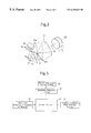
- FIG. 3 is a perspective view of the fundamental components of FIG. 1;
- FIG. 4 is a perspective view of an indicator plate having an information mask and an illumination light source, by way of example;
- FIG. 5 is a block diagram of a control system of a camera shown in FIG. 1;
- FIG. 6 is a plan view of another example of an information mask
- FIG. 7 is a graph showing an example of a transmittance of a semitransparent surface of a third reflection surface
- FIG. 8 is a graph showing another example of a transmittance of a semitransparent surface of a third reflection surface
- FIG. 9 is a sectional view of the fundamental components of a single lens reflex camera having an indicator within a finder, according to a second embodiment of the present invention.
- FIG. 10 is an enlarged view of the fundamental components of FIG. 9;
- FIG. 11 is a perspective view of the fundamental components of FIG. 9;
- FIG. 12 is a perspective view of an LCD panel having an information mask and an illumination light source, by way of example.
- FIG. 13 is a block diagram of a control system of a camera shown in FIG. 9 .
- FIGS. 1 through 5 show a single lens reflex camera having an indicator within a finder, according to a first embodiment of the present invention.
- This embodiment is applied to an indicator for indicating a selected object distance measuring area mask in a multi-point distance-measuring single lens reflex camera using a pentagonal prism.
- Object light transmitted through a photographic lens 11 is reflected by a main mirror 13 and is converged onto a focusing plate 15 which is optically equivalent to a film surface (imaging plane) 17 .
- a pentagonal prism 19 is positioned over the focusing plate 15 and is provided with a roof reflection surface (first and second reflection surfaces normal to each other) 19 a and a third reflection surface 19 b .
- the roof reflection surface 19 a reflects the object light transmitted through the focusing plate 15 toward the third reflection surface 19 b , and the object light reflected by the third reflection surface 19 b reaches an eyepiece 21 .
- the roof reflection surface 19 a and the third reflection surface 19 b of the pentagonal prism 19 constitute a reflection surface system together with the main mirror 13 , so that a viewer can view an object image as an erect image.
- the main mirror 13 is provided on the center portion thereof with a semitransparent surface (half mirror).
- the object light transmitted through the half mirror is reflected toward a multi-point distance-measuring AF module 25 by a sub mirror 23 .
- the multi-point distance-measuring AF module 25 measures (calculates) the defocus amount in a plurality of object distance measurement areas within a photographic field-of-view (as viewed through the finder).
- An AF drive system (not shown) drives the photographic lens 11 in accordance with the detected defocus amount signal, so that the photographic lens 11 is focused on an object within a selected distance-measurement area.
- the above-mentioned structure is a conventional multi-point distance-measuring single lens reflex camera known in the art.
- the third reflection surface 19 b of the pentagonal prism 19 is provided in a predetermined area with a semitransparent surface (half mirror), the center axis thereof being identical to the optical axis 21 x of the eyepiece 21 .
- An auxiliary prism 31 is cemented to the semitransparent surface of the third reflection surface 19 b .
- the auxiliary prism 31 is constructed from the same material as the pentagonal prism 19 so that the optical axis 21 x of the eyepiece 21 is not deflected at the cemented surface therebetween, and is provided with an emission surface 31 a which is perpendicular to the optical axis 21 x of the eyepiece 21 , so that the object light is not deflected (travels linearly).
- a diopter correcting lens 33 , a reflection mirror 35 , an indication plate 37 , and an illumination light source 39 are provided outside the auxiliary prism 31 in that order along the optical axis 21 x of the eyepiece 21 .
- the optical axis of the eyepiece 21 (optical axis 21 x ) is substantially identical to the superimposed optical axis (optical axis of the diopter correcting lens 33 ).
- the diopter correcting lens 33 having a positive power makes the position of the indicator plate 37 optically equivalent to the focusing plate 15 .
- the indicator plate 37 lies in a plane perpendicular to the optical axis 21 x .
- the indicator plate 37 is provided with five distance measuring area masks (information masks) 37 a , 37 b , 37 c , 37 d , and 37 e for multi-point distance-measurement (i.e., five-point distance-measurement in the illustrated embodiment).
- the illumination light source 39 includes five LEDs 39 a , 39 b , 39 c , 39 d , and 39 e corresponding to the five distance-measuring area masks, which can be selectively turned ON to emit light.
- the distance-measuring area masks 37 a through 37 e define a transparent area, and the remaining portion of the indicator plate 37 defines a non-transparent (opaque) area.
- the LEDs 39 a through 39 e of the illumination light source 39 are selectively turned ON to emit light via a control circuit 41 and an emission selection device 43 , as can be seen in FIG. 5 .
- the control circuit 41 receives data supplied from a distance-measuring area selection device 45 which selects the object distance measuring area to be used from among five distance-measuring areas, and distance data (defocus data) supplied from the multi-point distance-measuring AF module 25 .
- the control circuit 41 causes one of the LEDs 39 a , 39 b , 39 c , 39 d and 39 e , corresponding to one of the selected distance-measuring area masks 37 a , 37 b , 37 c , 37 d and 37 e , to emit light via the emission selection device 43 in accordance with the input distance data.
- the rays of light emitted from the LEDs 39 a through 39 e are transmitted through the corresponding distance-measuring area masks 37 a through 37 e , and are reflected by the reflection mirror 35 to enter the pentagonal prism 19 through the diopter correcting lens 33 and the auxiliary prism 31 .
- the rays of light emitted from the LEDs 39 a through 39 e can be viewed through the eyepiece 21 together with an object image formed on the focusing plate 15 . Since the rays of light emitted from the LEDs 39 a through 39 e emit light through the distance-measuring are masks 37 a through 37 e , the emitted light rays are indicated as information within the finder field-of-view.
- the distance-measuring area selection device 45 can be embodied as a manual switch or a line-of-sight detection switch, etc. In FIG. 5, a drive system for driving the photographic lens 11 , which is driven based on the distance data (defocus data) supplied from the multi-point distance-measuring AF module 25 is omitted.
- the color of light emitted from the light source 39 is visible when it is superimposed on the object image formed on the focusing plate 15 , and can be red, for example (wavelength: approximately 600 nm).
- the transmission characteristics of the semitransparent film formed on the third reflection surface 19 b are such that the light of the LEDs passing through the distance measuring area masks 37 a through 37 e which is directly incident on the viewer's eye is not obstructive, but can be clearly recognized. It has been confirmed through experimentation that it is preferable for the half mirror coating on the surface 19 b to have a transmittance of approximately 5% to 20%, and more preferably a transmittance of about 10%, wherein the light passing therethrough has, for example, a wavelength of approximately 600 nm.
- the transmission characteristics can be obtained by a coating which exhibits a uniform transmittance over the entire visible light wavelength band, as shown in FIG. 7, or by a coating which permits approximately 10% of light (i.e., only the wavelength band of approximately 600 nm) to pass therethrough, and prevents the remaining wavelengths of light from passing therethrough, as shown in FIG. 8 .
- a coating which exhibits a uniform transmittance over the entire visible light wavelength band as shown in FIG. 7
- Such coating technology is known in the art.
- the reduced light path length of the indicating optical system between the eyepiece 21 and the indicator plate 37 is decreased by an amount corresponding to the light path length of the pentagonal prism 19 and the auxiliary prism 31 having a refractive index more than 1; and hence, the power of the diopter correcting lens 33 can be reduced.
- the diopter correcting lens 33 makes it possible not only to correct the diopter of the finder while reducing the whole length of the indicating optical system, but also to make the indicator plate 37 smaller than the focusing plate 15 , thus miniaturizing the indicating optical system.
- FIG. 6 shows another example of the information masks provided on the indicator plate 37 .
- upper masks for a program mode, a strobe mode, a strobe prohibition mode, and a back light mode, in that order from left to right are shown, by way of example.
- FIGS. 9 through 13 show a second embodiment of the present invention, applied to a single lens reflex camera having an indicator within a finder.
- the information masks are used for indicating information within the finder field-of-view
- an LCD panel is used as the information indication device.
- the remaining structure of the second embodiment is substantially the same as that of the first embodiment, and hence, the elements corresponding to those in the first embodiment are designated with the same reference numbers. The following discussion will be addressed only to different aspects between the first and second embodiments.
- a diopter correcting lens 33 , a reflection mirror 35 , an LCD panel 38 , a projection lens 40 and an illumination light source 42 are arranged in this order on the optical axis 21 x outside the auxiliary prism 31 .
- the optical axis of the eyepiece 21 (optical axis 21 x ) is substantially identical to the superimposed optical axis (i.e., the optical axis of the diopter correcting lens 33 ).
- the diopter correcting lens 33 having a positive optical power, makes the position of the LCD panel 38 optically equivalent to the focusing plate 15 . It is possible to provide the whole, or a part of, the diopter correcting lens 33 on the emission surface of the auxiliary prism 31 .
- the LCD panel 38 lies in a plane perpendicular to the optical axis 21 x .
- the LCD panel 38 is provided with nine distance measuring area masks (information masks) 38 a in the form of a matrix of 3 ⁇ 3 in order to carry out a multi-point distance-measurement (i.e., nine-point distance-measurement in the illustrated embodiment).
- the distance-measuring area masks 38 a are each provided with a liquid crystal enclosed therein, which is normally opaque (non-transparent) and changes to a transparent state when a drive voltage is applied thereto.
- the illumination light source (LED) 42 illuminates the LCD panel 38 via the projection lens 40 .
- the projection lens 40 collimates the divergent light emitted from the light source 42 so that substantially parallel light is incident upon the LCD panel 38 . Consequently, the light of the light source 42 transmitted through any of distance-measuring area masks 38 a , which is turned into a transparent state, can reach the viewer's eye via the reflection mirror 35 , the auxiliary prism 31 , the pentagonal prism 19 and the eyepiece 21 .
- FIG. 12 shows a projection lens 40 constructed as a Fresnel lens. It is possible to provide at least one aspherical surface on the projection lens 40 to provide a uniform light distribution.
- the illumination light source 42 emits light via the control circuit 41 and the light source drive circuit 46 , as shown in FIG. 13 .
- the LCD panel 38 is driven via the control circuit 41 and an LCD panel drive circuit 44 .
- the control circuit 41 receives data supplied from a distance-measuring area selection device 45 which selects the object distance measuring area to be used from among the nine distance-measuring areas, and distance data (defocus data) supplied from the multi-point distance-measuring AF module 25 .
- the control circuit 41 supplies the voltage to the liquid crystal corresponding to the selected distance-measuring area mask 38 a via the LCD panel drive circuit 44 in accordance with the input data, so that the illumination light source emits light through the light source drive circuit 46 .
- the light emitted from the illumination light source 42 is transmitted through the distance-measuring area mask 38 a which has been turned into a transparent state, and is reflected by the reflection mirror 35 to enter the pentagonal prism 19 through the diopter correcting lens 33 and the auxiliary prism 31 . Consequently, the light emitted from the illumination light source 42 can be viewed through the eyepiece 21 together with an object image formed on the focusing plate 15 . Since the rays of light emitted from the illumination light source 42 are transmitted through the distance-measuring area masks 38 a , the emitted light rays are indicated as information within the finder field-of-view.
- the distance-measuring area selection device 45 can be embodied by a manual switch or a line-of-sight detection switch, etc.
- a drive system for driving the photographic lens 11 which is driven based on the distance data (defocus data) supplied from the multi-point distance-measuring AF module 25 is omitted.
- the color of light emitted from the light source 42 is one which is visible when superimposed on the object image formed on the focusing plate 15 , and can be red for example (wavelength: approximately 600 nm).
- the transmission characteristics of the semitransparent film formed on the third reflection surface 19 b is such that the light of the LEDs passing through the distance measuring area masks 38 a which is directly incident on the viewer's eye is not obstructive, but can be clearly recognized. It has been confirmed through experimentation that it is preferable for the half mirror coating on the surface 19 b to have a transmittance of approximately 5% to 20%, and more preferably a transmittance of about 10%, wherein the light passing therethrough has, for example, a wavelength of approximately 600 nm.
- the transmission characteristics can be obtained by a coating which exhibits a uniform transmittance over the entire visible light wavelength band, as shown in FIG. 7, or by a coating which permits approximately 10% of light (i.e., only the wavelength band of approximately 600 nm) to pass therethrough, and prevents the remaining wavelengths of light from passing therethrough, as shown in FIG. 8 .
- a coating which exhibits a uniform transmittance over the entire visible light wavelength band as shown in FIG. 7
- Such coating technology is known in the art.
- the reduced light path length of the indicating optical system between the eyepiece 21 and the LCD panel 38 is decreased by an amount corresponding to the light path length of the pentagonal prism 19 and the auxiliary prism 31 having a refractive index more than 1; and hence, the power of the diopter correcting lens 33 can be reduced.
- the diopter correcting lens 33 makes it possible not only to correct the diopter of the finder while reducing the whole length of the indicating optical system, but also to make the LCD panel 38 smaller than the focusing plate 15 , thus miniaturizing the indicating optical system.
- a pentagonal mirror i.e., a hollow mirror having reflection surfaces corresponding to the roof reflection surface 19 a and the third reflection surface 19 b of the pentagonal prism 19
- the auxiliary prism 31 can be omitted.
- the present invention not only can necessary information be clearly and correctly indicated within the field of the view of the finder without having an adverse influence on the fundamental functions of the view finder of a single lens reflex camera, but also a small indicator within a view finder can be provided.
- the present invention can be advantageously applied to a superimposed indicator, in which information is superimposed on an object image within the finder.
Abstract
Description
Claims (16)
Applications Claiming Priority (4)
| Application Number | Priority Date | Filing Date | Title |
|---|---|---|---|
| JP10368176A JP2000194052A (en) | 1998-12-24 | 1998-12-24 | Display device within finder for single-lens reflex camera |
| JP10-368176 | 1998-12-24 | ||
| JP10-368177 | 1998-12-24 | ||
| JP10368177A JP2000194053A (en) | 1998-12-24 | 1998-12-24 | Display device within finder for single-lens reflex camera |
Publications (1)
| Publication Number | Publication Date |
|---|---|
| US6292629B1 true US6292629B1 (en) | 2001-09-18 |
Family
ID=26581980
Family Applications (1)
| Application Number | Title | Priority Date | Filing Date |
|---|---|---|---|
| US09/469,358 Expired - Lifetime US6292629B1 (en) | 1998-12-24 | 1999-12-22 | Indicator provided within finder for single lens reflex camera |
Country Status (2)
| Country | Link |
|---|---|
| US (1) | US6292629B1 (en) |
| DE (1) | DE19962712C2 (en) |
Cited By (12)
| Publication number | Priority date | Publication date | Assignee | Title |
|---|---|---|---|---|
| US6717747B2 (en) | 2000-08-07 | 2004-04-06 | Enplas Corporation | Image pickup lens |
| US20040156629A1 (en) * | 2003-01-17 | 2004-08-12 | Pentax Corporation | Light-projecting device |
| US20040156116A1 (en) * | 2003-01-17 | 2004-08-12 | Pentax Corporation | Light-projecting device |
| US6879781B2 (en) | 2003-01-17 | 2005-04-12 | Pentax Corporation | Light-projecting device |
| FR2872303A1 (en) * | 2004-06-23 | 2005-12-30 | Pentax Corp | Single lens reflex type digital camera has superimposer that superimposes indicator mark on position of given focus point such that brightness of indicator mark is increased as luminance of position increases |
| US7046925B2 (en) | 2003-01-17 | 2006-05-16 | Pentax Corporation | Superimpose-plate for view finder |
| US20070172226A1 (en) * | 2006-01-25 | 2007-07-26 | Pentax Corporation | Digital single-lens reflex camera |
| WO2007128189A1 (en) * | 2006-05-08 | 2007-11-15 | Beijing Athletic Sports International Economical Conference Service Center | Digital camera |
| US20080170849A1 (en) * | 2006-05-19 | 2008-07-17 | Pentax Corporation | Light-emitting unit and superimposing device |
| US20130243414A1 (en) * | 2012-02-01 | 2013-09-19 | Leica Camera Ag | Illumination arrangement for an image field delimitation frame of a mixed-image viewfinder camera |
| US20140168499A1 (en) * | 2012-12-18 | 2014-06-19 | Ricoh Imaging Company, Ltd. | Optical Device and Single Lens Reflex Camera |
| US20220279095A1 (en) * | 2019-12-24 | 2022-09-01 | Nec Corporation | Gate apparatus, control method of same, and program |
Families Citing this family (2)
| Publication number | Priority date | Publication date | Assignee | Title |
|---|---|---|---|---|
| JP3718415B2 (en) * | 2000-07-05 | 2005-11-24 | ペンタックス株式会社 | Multi-point automatic focus detection device |
| WO2022188166A1 (en) * | 2021-03-12 | 2022-09-15 | 欧菲光集团股份有限公司 | Camera lens module, photographing module and electronic device |
Citations (8)
| Publication number | Priority date | Publication date | Assignee | Title |
|---|---|---|---|---|
| US3094911A (en) * | 1958-12-09 | 1963-06-25 | Voigtlaender Ag | Photographic camera |
| US3687038A (en) * | 1970-04-28 | 1972-08-29 | Nippon Kogaku Kk | Viewfinder system for a single lens reflex camera |
| JPH03140930A (en) | 1989-10-26 | 1991-06-14 | Canon Inc | In-the-finder display device of single-lens reflex camera |
| JPH03192340A (en) | 1989-12-22 | 1991-08-22 | Canon Inc | Indication device within finder for single-lens reflex camera |
| US5361119A (en) * | 1991-01-08 | 1994-11-01 | Nikon Corporation | Focus state display device for camera |
| US5473403A (en) * | 1992-05-22 | 1995-12-05 | Canon Kabushiki Kaisha | Camera having a multi-point focus detecting device |
| US5754900A (en) * | 1996-02-28 | 1998-05-19 | Canon Kabushiki Kaisha | Intra-viewfinder display device and optical apparatus |
| US5969869A (en) | 1996-10-25 | 1999-10-19 | Asahi Kogaku Kogyo Kabushiki Kaisha | Prism |
Family Cites Families (2)
| Publication number | Priority date | Publication date | Assignee | Title |
|---|---|---|---|---|
| US5313327A (en) * | 1990-11-30 | 1994-05-17 | Asahi Kogaku Kogyo Kabushiki Kaisha | Ocular lens |
| GB2263175B (en) * | 1992-01-13 | 1995-02-15 | Asahi Optical Co Ltd | Eye direction detecting apparatus of camera view finder |
-
1999
- 1999-12-22 US US09/469,358 patent/US6292629B1/en not_active Expired - Lifetime
- 1999-12-23 DE DE19962712A patent/DE19962712C2/en not_active Expired - Fee Related
Patent Citations (8)
| Publication number | Priority date | Publication date | Assignee | Title |
|---|---|---|---|---|
| US3094911A (en) * | 1958-12-09 | 1963-06-25 | Voigtlaender Ag | Photographic camera |
| US3687038A (en) * | 1970-04-28 | 1972-08-29 | Nippon Kogaku Kk | Viewfinder system for a single lens reflex camera |
| JPH03140930A (en) | 1989-10-26 | 1991-06-14 | Canon Inc | In-the-finder display device of single-lens reflex camera |
| JPH03192340A (en) | 1989-12-22 | 1991-08-22 | Canon Inc | Indication device within finder for single-lens reflex camera |
| US5361119A (en) * | 1991-01-08 | 1994-11-01 | Nikon Corporation | Focus state display device for camera |
| US5473403A (en) * | 1992-05-22 | 1995-12-05 | Canon Kabushiki Kaisha | Camera having a multi-point focus detecting device |
| US5754900A (en) * | 1996-02-28 | 1998-05-19 | Canon Kabushiki Kaisha | Intra-viewfinder display device and optical apparatus |
| US5969869A (en) | 1996-10-25 | 1999-10-19 | Asahi Kogaku Kogyo Kabushiki Kaisha | Prism |
Cited By (17)
| Publication number | Priority date | Publication date | Assignee | Title |
|---|---|---|---|---|
| US6717747B2 (en) | 2000-08-07 | 2004-04-06 | Enplas Corporation | Image pickup lens |
| US20040156629A1 (en) * | 2003-01-17 | 2004-08-12 | Pentax Corporation | Light-projecting device |
| US20040156116A1 (en) * | 2003-01-17 | 2004-08-12 | Pentax Corporation | Light-projecting device |
| US6879781B2 (en) | 2003-01-17 | 2005-04-12 | Pentax Corporation | Light-projecting device |
| US6903885B2 (en) | 2003-01-17 | 2005-06-07 | Pentax Corporation | Light-projecting device |
| US6941069B2 (en) | 2003-01-17 | 2005-09-06 | Pentax Corporation | Light-projecting device |
| US7046925B2 (en) | 2003-01-17 | 2006-05-16 | Pentax Corporation | Superimpose-plate for view finder |
| FR2872303A1 (en) * | 2004-06-23 | 2005-12-30 | Pentax Corp | Single lens reflex type digital camera has superimposer that superimposes indicator mark on position of given focus point such that brightness of indicator mark is increased as luminance of position increases |
| US20070172226A1 (en) * | 2006-01-25 | 2007-07-26 | Pentax Corporation | Digital single-lens reflex camera |
| WO2007128189A1 (en) * | 2006-05-08 | 2007-11-15 | Beijing Athletic Sports International Economical Conference Service Center | Digital camera |
| US20080170849A1 (en) * | 2006-05-19 | 2008-07-17 | Pentax Corporation | Light-emitting unit and superimposing device |
| US7636520B2 (en) * | 2006-05-19 | 2009-12-22 | Hoya Corporation | Light-emitting unit and superimposing device |
| US20130243414A1 (en) * | 2012-02-01 | 2013-09-19 | Leica Camera Ag | Illumination arrangement for an image field delimitation frame of a mixed-image viewfinder camera |
| US8953935B2 (en) * | 2012-02-01 | 2015-02-10 | Leica Camera Ag | Illumination arrangement for an image field delimitation frame of a mixed-image viewfinder camera |
| US20140168499A1 (en) * | 2012-12-18 | 2014-06-19 | Ricoh Imaging Company, Ltd. | Optical Device and Single Lens Reflex Camera |
| US9179049B2 (en) * | 2012-12-18 | 2015-11-03 | Ricoh Imaging Company, Ltd. | Optical device and single lens reflex camera |
| US20220279095A1 (en) * | 2019-12-24 | 2022-09-01 | Nec Corporation | Gate apparatus, control method of same, and program |
Also Published As
| Publication number | Publication date |
|---|---|
| DE19962712A1 (en) | 2000-06-29 |
| DE19962712C2 (en) | 2003-12-18 |
Similar Documents
| Publication | Publication Date | Title |
|---|---|---|
| US5473403A (en) | Camera having a multi-point focus detecting device | |
| US6292629B1 (en) | Indicator provided within finder for single lens reflex camera | |
| US4743932A (en) | Focus detection device for a camera | |
| US5754900A (en) | Intra-viewfinder display device and optical apparatus | |
| US5053803A (en) | Information display apparatus for camera | |
| US5489965A (en) | Finder display apparatus | |
| US5262819A (en) | Compact focus detecting device suitable for incorporation into an optical apparatus | |
| US5581318A (en) | Viewfinder unit in a camera | |
| US4171888A (en) | Finder optical system for a single lens reflex camera | |
| US4907026A (en) | Light projection system for automatic focus detection | |
| US5526083A (en) | Finder system of a camera | |
| US6714244B1 (en) | Internal indication of a viewfinder of a camera | |
| US5850578A (en) | Light-projecting system for automatic focus detection | |
| US4544252A (en) | Apparatus for displaying information in camera view finder | |
| US5761543A (en) | Apparatus for measuring anterior eye portion | |
| JP2749829B2 (en) | Single-lens reflex camera body to display in viewfinder | |
| JP2001075149A (en) | Display device within finder screen | |
| JP2000122156A (en) | Display device for camera | |
| JPH095836A (en) | Camera provided with in-finder display device | |
| JP2000194053A (en) | Display device within finder for single-lens reflex camera | |
| US20020008189A1 (en) | Surveying instrument having a phase-difference detection type focus detecting device | |
| JP3445052B2 (en) | Display device in viewfinder | |
| JP2000089336A (en) | Display device within finder picture plane | |
| JPH0843913A (en) | Displaying apparatus in finder of camera | |
| JP2000194052A (en) | Display device within finder for single-lens reflex camera |
Legal Events
| Date | Code | Title | Description |
|---|---|---|---|
| AS | Assignment |
Owner name: ASAHI KOGAKU KOGYO KABUSHIKI KAISHA, JAPAN Free format text: ASSIGNMENT OF ASSIGNORS INTEREST;ASSIGNOR:SENSUI, TAKAYUKI;REEL/FRAME:010476/0631 Effective date: 19991217 |
|
| STCF | Information on status: patent grant |
Free format text: PATENTED CASE |
|
| FEPP | Fee payment procedure |
Free format text: PAYOR NUMBER ASSIGNED (ORIGINAL EVENT CODE: ASPN); ENTITY STATUS OF PATENT OWNER: LARGE ENTITY |
|
| FPAY | Fee payment |
Year of fee payment: 4 |
|
| FPAY | Fee payment |
Year of fee payment: 8 |
|
| AS | Assignment |
Owner name: HOYA CORPORATION, JAPAN Free format text: MERGER;ASSIGNOR:ASAHI KOGAKU KOGYO KABUSHIKI KAISHA;REEL/FRAME:026970/0621 Effective date: 20080331 |
|
| AS | Assignment |
Owner name: PENTAX RICOH IMAGING COMPANY, LTD., JAPAN Free format text: CORPORATE SPLIT;ASSIGNOR:HOYA CORPORATION;REEL/FRAME:027315/0115 Effective date: 20111003 |
|
| FPAY | Fee payment |
Year of fee payment: 12 |