US6295375B1 - Method and device for coding a sequence of pictures - Google Patents
Method and device for coding a sequence of pictures Download PDFInfo
- Publication number
- US6295375B1 US6295375B1 US09/253,084 US25308499A US6295375B1 US 6295375 B1 US6295375 B1 US 6295375B1 US 25308499 A US25308499 A US 25308499A US 6295375 B1 US6295375 B1 US 6295375B1
- Authority
- US
- United States
- Prior art keywords
- pictures
- sub
- picture
- coding
- values
- Prior art date
- Legal status (The legal status is an assumption and is not a legal conclusion. Google has not performed a legal analysis and makes no representation as to the accuracy of the status listed.)
- Expired - Lifetime
Links
Images
Classifications
-
- H—ELECTRICITY
- H04—ELECTRIC COMMUNICATION TECHNIQUE
- H04N—PICTORIAL COMMUNICATION, e.g. TELEVISION
- H04N19/00—Methods or arrangements for coding, decoding, compressing or decompressing digital video signals
- H04N19/10—Methods or arrangements for coding, decoding, compressing or decompressing digital video signals using adaptive coding
- H04N19/169—Methods or arrangements for coding, decoding, compressing or decompressing digital video signals using adaptive coding characterised by the coding unit, i.e. the structural portion or semantic portion of the video signal being the object or the subject of the adaptive coding
- H04N19/18—Methods or arrangements for coding, decoding, compressing or decompressing digital video signals using adaptive coding characterised by the coding unit, i.e. the structural portion or semantic portion of the video signal being the object or the subject of the adaptive coding the unit being a set of transform coefficients
-
- H—ELECTRICITY
- H04—ELECTRIC COMMUNICATION TECHNIQUE
- H04N—PICTORIAL COMMUNICATION, e.g. TELEVISION
- H04N19/00—Methods or arrangements for coding, decoding, compressing or decompressing digital video signals
- H04N19/10—Methods or arrangements for coding, decoding, compressing or decompressing digital video signals using adaptive coding
- H04N19/102—Methods or arrangements for coding, decoding, compressing or decompressing digital video signals using adaptive coding characterised by the element, parameter or selection affected or controlled by the adaptive coding
- H04N19/124—Quantisation
- H04N19/126—Details of normalisation or weighting functions, e.g. normalisation matrices or variable uniform quantisers
-
- H—ELECTRICITY
- H04—ELECTRIC COMMUNICATION TECHNIQUE
- H04N—PICTORIAL COMMUNICATION, e.g. TELEVISION
- H04N19/00—Methods or arrangements for coding, decoding, compressing or decompressing digital video signals
- H04N19/10—Methods or arrangements for coding, decoding, compressing or decompressing digital video signals using adaptive coding
- H04N19/134—Methods or arrangements for coding, decoding, compressing or decompressing digital video signals using adaptive coding characterised by the element, parameter or criterion affecting or controlling the adaptive coding
- H04N19/136—Incoming video signal characteristics or properties
- H04N19/14—Coding unit complexity, e.g. amount of activity or edge presence estimation
-
- H—ELECTRICITY
- H04—ELECTRIC COMMUNICATION TECHNIQUE
- H04N—PICTORIAL COMMUNICATION, e.g. TELEVISION
- H04N19/00—Methods or arrangements for coding, decoding, compressing or decompressing digital video signals
- H04N19/10—Methods or arrangements for coding, decoding, compressing or decompressing digital video signals using adaptive coding
- H04N19/134—Methods or arrangements for coding, decoding, compressing or decompressing digital video signals using adaptive coding characterised by the element, parameter or criterion affecting or controlling the adaptive coding
- H04N19/154—Measured or subjectively estimated visual quality after decoding, e.g. measurement of distortion
-
- H—ELECTRICITY
- H04—ELECTRIC COMMUNICATION TECHNIQUE
- H04N—PICTORIAL COMMUNICATION, e.g. TELEVISION
- H04N19/00—Methods or arrangements for coding, decoding, compressing or decompressing digital video signals
- H04N19/10—Methods or arrangements for coding, decoding, compressing or decompressing digital video signals using adaptive coding
- H04N19/169—Methods or arrangements for coding, decoding, compressing or decompressing digital video signals using adaptive coding characterised by the coding unit, i.e. the structural portion or semantic portion of the video signal being the object or the subject of the adaptive coding
- H04N19/17—Methods or arrangements for coding, decoding, compressing or decompressing digital video signals using adaptive coding characterised by the coding unit, i.e. the structural portion or semantic portion of the video signal being the object or the subject of the adaptive coding the unit being an image region, e.g. an object
- H04N19/176—Methods or arrangements for coding, decoding, compressing or decompressing digital video signals using adaptive coding characterised by the coding unit, i.e. the structural portion or semantic portion of the video signal being the object or the subject of the adaptive coding the unit being an image region, e.g. an object the region being a block, e.g. a macroblock
-
- H—ELECTRICITY
- H04—ELECTRIC COMMUNICATION TECHNIQUE
- H04N—PICTORIAL COMMUNICATION, e.g. TELEVISION
- H04N19/00—Methods or arrangements for coding, decoding, compressing or decompressing digital video signals
- H04N19/60—Methods or arrangements for coding, decoding, compressing or decompressing digital video signals using transform coding
-
- H—ELECTRICITY
- H04—ELECTRIC COMMUNICATION TECHNIQUE
- H04N—PICTORIAL COMMUNICATION, e.g. TELEVISION
- H04N19/00—Methods or arrangements for coding, decoding, compressing or decompressing digital video signals
- H04N19/10—Methods or arrangements for coding, decoding, compressing or decompressing digital video signals using adaptive coding
- H04N19/134—Methods or arrangements for coding, decoding, compressing or decompressing digital video signals using adaptive coding characterised by the element, parameter or criterion affecting or controlling the adaptive coding
- H04N19/146—Data rate or code amount at the encoder output
- H04N19/149—Data rate or code amount at the encoder output by estimating the code amount by means of a model, e.g. mathematical model or statistical model
-
- H—ELECTRICITY
- H04—ELECTRIC COMMUNICATION TECHNIQUE
- H04N—PICTORIAL COMMUNICATION, e.g. TELEVISION
- H04N19/00—Methods or arrangements for coding, decoding, compressing or decompressing digital video signals
- H04N19/10—Methods or arrangements for coding, decoding, compressing or decompressing digital video signals using adaptive coding
- H04N19/134—Methods or arrangements for coding, decoding, compressing or decompressing digital video signals using adaptive coding characterised by the element, parameter or criterion affecting or controlling the adaptive coding
- H04N19/146—Data rate or code amount at the encoder output
- H04N19/15—Data rate or code amount at the encoder output by monitoring actual compressed data size at the memory before deciding storage at the transmission buffer
-
- H—ELECTRICITY
- H04—ELECTRIC COMMUNICATION TECHNIQUE
- H04N—PICTORIAL COMMUNICATION, e.g. TELEVISION
- H04N19/00—Methods or arrangements for coding, decoding, compressing or decompressing digital video signals
- H04N19/10—Methods or arrangements for coding, decoding, compressing or decompressing digital video signals using adaptive coding
- H04N19/134—Methods or arrangements for coding, decoding, compressing or decompressing digital video signals using adaptive coding characterised by the element, parameter or criterion affecting or controlling the adaptive coding
- H04N19/146—Data rate or code amount at the encoder output
- H04N19/152—Data rate or code amount at the encoder output by measuring the fullness of the transmission buffer
-
- H—ELECTRICITY
- H04—ELECTRIC COMMUNICATION TECHNIQUE
- H04N—PICTORIAL COMMUNICATION, e.g. TELEVISION
- H04N19/00—Methods or arrangements for coding, decoding, compressing or decompressing digital video signals
- H04N19/30—Methods or arrangements for coding, decoding, compressing or decompressing digital video signals using hierarchical techniques, e.g. scalability
Definitions
- the present invention relates to a method of coding a sequence of pictures comprising at least the steps of:
- This invention may be used particularly for the implementation of MPEG-2 encoders.
- the main principle of image compression techniques is to remove spatial and temporal data redundancy.
- the MPEG standard for instance, is based on the two following techniques: discrete cosine transform (DCT) and motion compensation (as described for example in the following document “MPEG video coding: a basic tutorial introduction”, S. R. Ely, BBC Report RD 1996/3).
- DCT discrete cosine transform
- motion compensation as described for example in the following document “MPEG video coding: a basic tutorial introduction”, S. R. Ely, BBC Report RD 1996/3).
- a conventional MPEG-2 encoder mainly comprises, as indicated in FIG. 1, a formatting circuit 11 , receiving each digitized picture of the concerned video sequence and intended to subdivide a picture signal—composed of a bidimensional array of picture elements, or pixels—into disjoint sub-pictures or blocks of smaller size (8 ⁇ 8 or 16 ⁇ 16 pixels), a DCT circuit 12 , intended to apply to each block of pixels a bidimensional discrete cosine transform (the transform coefficients thus obtained being generally normalized to a predetermined range), a quantization circuit 13 intended to compress by thresholding and quantization (with a variable quantizer scale) the bidimensional array of the transform coefficients thus obtained for each block of pixels, a variable length encoding circuit 14 , and a motion-compensated prediction circuit 15 .
- a formatting circuit 11 receiving each digitized picture of the concerned video sequence and intended to subdivide a picture signal—composed of a bidimensional array of picture elements, or pixels—into disjoint sub-pictures or blocks of smaller size (8
- Said prediction circuit finds for each block a motion vector matching this block to another one in the previous picture of the sequence, displaces said previous block according to the motion vector, and subtracts (the subtracter is here assumed to be included into the prediction circuit 15 ) the predicted picture thus obtained from the current one for delivering the difference picture that will be transformed, quantized and coded.
- a picture type defines which prediction mode, I, P, or B, will be used to code each macroblock: I type corresponds to I-pictures coded without reference to other pictures, P type to P-pictures coded using motion-compensated prediction from a past I- or P-picture, and B type to B-pictures using both past and future I- or P-pictures for motion compensation.
- a buffer 16 allows to store the output coded signals and to smooth out the variations in the output bit rate, and a rate control and quantizer scale variation circuit 17 , provided between said buffer and the quantization circuit 13 , allows to adjust the variable quantizer scale.
- HVS human visual system
- L is the luminance difference to the background and LB is the background luminance.
- another contrast definition may be given: it is then defined as the ratio of a band-limited version of the picture—which is decomposed by the HVS into a set of sub-pictures expressed in several frequency bands and various orientations—over the mean luminance contained in the lower remaining frequency bands (when such a multi-resolution HVS model is thus considered, the contrast assessment requires two steps, a first one for decomposing the picture into a set of sub-pictures at various scales and orientations, with a pyramidal decomposition such as the Simoncelli pyramid, and a second one for computing the contrast for each scale and each orientation).
- the masking effect is then taken into account through a masking function which is applied to the obtained contrast information; this effect corresponds to the variation of a stimulus visibility threshold as a function of the luminance present in the neighbourhood of this stimulus.
- a signal the stimulus
- this effect corresponds to the variation of a stimulus visibility threshold as a function of the luminance present in the neighbourhood of this stimulus.
- the object of the invention is to improve the visual quality obtained by means of such an adaptive quantization.
- the invention relates to a coding method such as defined in the preamble of the description, said method being further characterized in that it also comprises, before said quantizing step, the additional sub-steps of:
- a is a constant provided for controlling the modulation amplitude.
- the invention also relates, for carrying out said method, to a device for coding a sequence of pictures comprising at least formatting means for subdividing each input picture into sub-pictures, quantization means, provided for compressing by thresholding and quantization a digital bitstream corresponding to said pictures, encoding means, provided for coding the output signals of said quantizing means, and rate control and quantizer scale variation means, provided for ensuring a constant bit rate at the output of said coding device, characterized in that said device also comprises, in series between its input and said quantizing means, bit reallocation control means including:
- a is a constant provided for controlling the modulation amplitude.
- FIG. 1 depicts the main circuits of a conventional MPEG-2 encoder
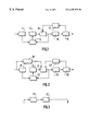
- FIG. 2 illustrates an encoder according to the present invention
- FIG. 3 shows in greater detail an essential circuit of the encoder of FIG. 2 .
- bit allocation is mainly dependent on the quantizer scale (one per macroblock), determined to ensure a constant bit rate at the output of the encoder: a lower (resp. higher) quantizer scale results in a better (resp.worse) image quality and a higher (resp.lower) number of coding bits.
- a lower (resp. higher) quantizer scale results in a better (resp.worse) image quality and a higher (resp.lower) number of coding bits.
- the amount of bits that can be allocated for the current macroblock to be encoded is first determined (rate controlling step). This target bit number then allows to set a reference value of the quantizer scale Q(i) for said macroblock.
- An adaptive quantization is finally carried out by means of a modulation of this reference value of the quantizer scale according to the spatial activity of the macroblock.
- the invention noticeably increases said quality by replacing the prior art structure by the structure of the encoder shown in FIG. 2 .
- the formatting circuit, the DCT circuit, the quantization circuit, the encoding circuit, the prediction circuit, the output buffer and the rate control and quantizer scale variation circuit are now designated by the references 21 to 27 respectively.
- Said rate control and quantizer scale variation circuit 27 is provided as previously between the buffer 25 and the quantization circuit 23 .
- a bit reallocation control circuit 30 detailed in FIG. 3, is provided for carrying out the principle of the present invention.
- the circuit 30 comprises an HVS modeling circuit 31 that receives each input picture and processes it in order to decompose it into a set of pictures and to compute the contrast and the masking for each of them, which allows to generate perceptual weighting factors.
- Said processing for the computation of the coefficients W(i) (in the circuit 32 ) is then the following. First these coefficients must be greater than 1 when the sensitivity is low, thus leading to a higher quantizer scale, and lower than 1 when the sensitivity is high.
- Q(av) is the average quantizer scale over the picture.
- the quantizer scale Q(av) is also not modified by the quantizer parameter modulation i.e. if:
- F(S(i)) is the cumulative distribution function of the sensitivity and a is a constant allowing to control the modulation amplitude.
- the perceptual modulation coefficients W(i) are greater than 1 for half of the macroblocks and lower than 1 for the other half.
- the modulation amplitude is dependent both on the eye sensitivity and on the occurrence frequency of this sensitivity.
- bits are reallocated preferably to sensitive areas, while ensuring that the rate control performance is not modified.
Abstract
Description


Claims (2)
Applications Claiming Priority (4)
| Application Number | Priority Date | Filing Date | Title |
|---|---|---|---|
| EP98400420 | 1998-02-20 | ||
| EP98400420 | 1998-02-20 | ||
| EP98402670 | 1998-10-27 | ||
| EP98402670 | 1998-10-27 |
Publications (1)
| Publication Number | Publication Date |
|---|---|
| US6295375B1 true US6295375B1 (en) | 2001-09-25 |
Family
ID=26151579
Family Applications (1)
| Application Number | Title | Priority Date | Filing Date |
|---|---|---|---|
| US09/253,084 Expired - Lifetime US6295375B1 (en) | 1998-02-20 | 1999-02-19 | Method and device for coding a sequence of pictures |
Country Status (5)
| Country | Link |
|---|---|
| US (1) | US6295375B1 (en) |
| EP (1) | EP0978200A2 (en) |
| JP (1) | JP2001520854A (en) |
| KR (1) | KR20010012071A (en) |
| WO (1) | WO1999043163A2 (en) |
Cited By (7)
| Publication number | Priority date | Publication date | Assignee | Title |
|---|---|---|---|---|
| US20050286786A1 (en) * | 2004-06-17 | 2005-12-29 | Reiko Noda | Apparatus and method for coding image based on level of visual attention and level of perceivable image quality distortion, and computer program product therefor |
| US20060013298A1 (en) * | 2004-06-27 | 2006-01-19 | Xin Tong | Multi-pass video encoding |
| US20060182175A1 (en) * | 2005-02-14 | 2006-08-17 | Kabushiki Kaisha Toshiba | Image encoding apparatus, image encoding method, and computer program product |
| US20060245492A1 (en) * | 2005-04-28 | 2006-11-02 | Thomas Pun | Single pass rate controller |
| US20090103618A1 (en) * | 2007-10-17 | 2009-04-23 | Koji Arimura | Picture coding apparatus and picture coding method |
| US8594190B2 (en) | 2004-06-27 | 2013-11-26 | Apple Inc. | Encoding with visual masking |
| US10785490B2 (en) | 2017-02-01 | 2020-09-22 | Samsung Electronics Co., Ltd. | Video coding module and method of operating the same |
Families Citing this family (4)
| Publication number | Priority date | Publication date | Assignee | Title |
|---|---|---|---|---|
| GB2362533A (en) | 2000-05-15 | 2001-11-21 | Nokia Mobile Phones Ltd | Encoding a video signal with an indicator of the type of error concealment used |
| WO2006004605A2 (en) * | 2004-06-27 | 2006-01-12 | Apple Computer, Inc. | Multi-pass video encoding |
| KR100788703B1 (en) * | 2006-02-24 | 2007-12-26 | 삼성전자주식회사 | Method and apparatus for video encoding and decoding |
| KR101394151B1 (en) | 2007-10-04 | 2014-05-14 | 삼성전자주식회사 | Apparatus and method for encoding image using a psycho-visual characteristic |
Citations (7)
| Publication number | Priority date | Publication date | Assignee | Title |
|---|---|---|---|---|
| US5136376A (en) * | 1989-10-14 | 1992-08-04 | Sony Corporation | Method of coding video signals and transmission system thereof |
| EP0535963A2 (en) | 1991-10-02 | 1993-04-07 | Matsushita Electric Industrial Co., Ltd. | Orthogonal transformation encoder |
| WO1993018611A1 (en) | 1992-03-09 | 1993-09-16 | Siemens Aktiengesellschaft | Image-adaptive process for regulating the length of a quantification interval during image data reduction |
| US5321440A (en) * | 1991-06-07 | 1994-06-14 | Sony Corporation | High efficiency data compressed image encoding |
| US5621465A (en) * | 1995-04-11 | 1997-04-15 | Matsushita Electric Industrial Co., Ltd. | Color image encoder |
| US5684714A (en) * | 1995-05-08 | 1997-11-04 | Kabushiki Kaisha Toshiba | Method and system for a user to manually alter the quality of a previously encoded video sequence |
| US6038256A (en) * | 1996-12-31 | 2000-03-14 | C-Cube Microsystems Inc. | Statistical multiplexed video encoding using pre-encoding a priori statistics and a priori and a posteriori statistics |
Family Cites Families (1)
| Publication number | Priority date | Publication date | Assignee | Title |
|---|---|---|---|---|
| EP0660619A1 (en) * | 1993-12-22 | 1995-06-28 | Laboratoires D'electronique Philips S.A.S. | Method for image variable length coding and device for carrying such method |
-
1999
- 1999-02-11 EP EP99902731A patent/EP0978200A2/en not_active Withdrawn
- 1999-02-11 JP JP54229799A patent/JP2001520854A/en active Pending
- 1999-02-11 KR KR1019997009672A patent/KR20010012071A/en not_active Application Discontinuation
- 1999-02-11 WO PCT/IB1999/000236 patent/WO1999043163A2/en not_active Application Discontinuation
- 1999-02-19 US US09/253,084 patent/US6295375B1/en not_active Expired - Lifetime
Patent Citations (10)
| Publication number | Priority date | Publication date | Assignee | Title |
|---|---|---|---|---|
| US5136376A (en) * | 1989-10-14 | 1992-08-04 | Sony Corporation | Method of coding video signals and transmission system thereof |
| US5321440A (en) * | 1991-06-07 | 1994-06-14 | Sony Corporation | High efficiency data compressed image encoding |
| EP0535963A2 (en) | 1991-10-02 | 1993-04-07 | Matsushita Electric Industrial Co., Ltd. | Orthogonal transformation encoder |
| US5369439A (en) * | 1991-10-02 | 1994-11-29 | Matsushita Electric Industrial Co., Ltd. | Orthogonal transform encoder using DC component to control quantization step size |
| WO1993018611A1 (en) | 1992-03-09 | 1993-09-16 | Siemens Aktiengesellschaft | Image-adaptive process for regulating the length of a quantification interval during image data reduction |
| US5621465A (en) * | 1995-04-11 | 1997-04-15 | Matsushita Electric Industrial Co., Ltd. | Color image encoder |
| US5684714A (en) * | 1995-05-08 | 1997-11-04 | Kabushiki Kaisha Toshiba | Method and system for a user to manually alter the quality of a previously encoded video sequence |
| US6038256A (en) * | 1996-12-31 | 2000-03-14 | C-Cube Microsystems Inc. | Statistical multiplexed video encoding using pre-encoding a priori statistics and a priori and a posteriori statistics |
| US6094457A (en) * | 1996-12-31 | 2000-07-25 | C-Cube Microsystems, Inc. | Statistical multiplexed video encoding using pre-encoding a priori statistics and a priori and a posteriori statistics |
| US6192083B1 (en) * | 1996-12-31 | 2001-02-20 | C-Cube Semiconductor Ii | Statistical multiplexed video encoding using pre-encoding a priori statistics and a priori and a posteriori statistics |
Non-Patent Citations (1)
| Title |
|---|
| Research and Development Report "MPEG Video Coding: A Basic Tutorial Introduction", by S.R. Ely, BBC Report RD 1996/3. |
Cited By (12)
| Publication number | Priority date | Publication date | Assignee | Title |
|---|---|---|---|---|
| US20050286786A1 (en) * | 2004-06-17 | 2005-12-29 | Reiko Noda | Apparatus and method for coding image based on level of visual attention and level of perceivable image quality distortion, and computer program product therefor |
| US7502518B2 (en) * | 2004-06-17 | 2009-03-10 | Kabushiki Kaisha Toshiba | Apparatus and method for coding image based on level of visual attention and level of perceivable image quality distortion, and computer program product therefor |
| US20060013298A1 (en) * | 2004-06-27 | 2006-01-19 | Xin Tong | Multi-pass video encoding |
| US8406293B2 (en) | 2004-06-27 | 2013-03-26 | Apple Inc. | Multi-pass video encoding based on different quantization parameters |
| US8594190B2 (en) | 2004-06-27 | 2013-11-26 | Apple Inc. | Encoding with visual masking |
| US8811475B2 (en) | 2004-06-27 | 2014-08-19 | Apple Inc. | Multi-pass video encoding solution for buffer underflow |
| US20060182175A1 (en) * | 2005-02-14 | 2006-08-17 | Kabushiki Kaisha Toshiba | Image encoding apparatus, image encoding method, and computer program product |
| US20060245492A1 (en) * | 2005-04-28 | 2006-11-02 | Thomas Pun | Single pass rate controller |
| US8208536B2 (en) | 2005-04-28 | 2012-06-26 | Apple Inc. | Method and apparatus for encoding using single pass rate controller |
| US20090103618A1 (en) * | 2007-10-17 | 2009-04-23 | Koji Arimura | Picture coding apparatus and picture coding method |
| US8396125B2 (en) * | 2007-10-17 | 2013-03-12 | Panasonic Corporation | Picture coding apparatus and picture coding method |
| US10785490B2 (en) | 2017-02-01 | 2020-09-22 | Samsung Electronics Co., Ltd. | Video coding module and method of operating the same |
Also Published As
| Publication number | Publication date |
|---|---|
| WO1999043163A3 (en) | 1999-11-11 |
| JP2001520854A (en) | 2001-10-30 |
| KR20010012071A (en) | 2001-02-15 |
| EP0978200A2 (en) | 2000-02-09 |
| WO1999043163A2 (en) | 1999-08-26 |
Similar Documents
| Publication | Publication Date | Title |
|---|---|---|
| US6535555B1 (en) | Quantizing method and device for video compression | |
| US6347116B1 (en) | Non-linear quantizer for video coding | |
| EP0422404B1 (en) | Transform coding using coefficient prediction techniques | |
| EP0723375B1 (en) | Post-processing device and method for eliminating blocking artifacts from decompressed images | |
| US6259823B1 (en) | Signal adaptive filtering method and signal adaptive filter for reducing blocking effect and ringing noise | |
| JP4187405B2 (en) | Object-based rate control apparatus and method in coding system | |
| KR100559924B1 (en) | Apparatus and method for macroblock based rate control in a coding system | |
| US20020186890A1 (en) | Dynamic filtering for lossy compression | |
| EP0577350B1 (en) | A video signal coding and decoding apparatus with an adaptive edge enhancement filter | |
| JP3721716B2 (en) | Image information encoding apparatus and method | |
| US20060002467A1 (en) | System, method and computer-readable medium for encoding a signal into macroblocks | |
| US6295375B1 (en) | Method and device for coding a sequence of pictures | |
| EP1569458A1 (en) | Encoding and decoding of video images based on a non-linear quantization | |
| US6363113B1 (en) | Methods and apparatus for context-based perceptual quantization | |
| US20030081848A1 (en) | Image encoder, image encoding method and image-encoding program | |
| EP0784408B1 (en) | Video encoder and decoder | |
| KR20010032337A (en) | Video signal encoding method, video signal encoder, and program recorded medium | |
| WO2000048090A1 (en) | An image compression system and method of determining quantisation parameters therefor | |
| US8045816B2 (en) | Image quantization method and apparatus with color distortion removing quantization matrix | |
| Westen et al. | Adaptive spatial noise shaping for DCT based image compression | |
| US7606436B2 (en) | Image encoding apparatus and quantization control method | |
| EP1589762A1 (en) | Image compression with reduced block artefacts | |
| JPH0746595A (en) | Moving image encoder and decoder | |
| US6347115B1 (en) | Method and system for predictive coding of images treated with the Roberts Method | |
| JP2626367B2 (en) | Video information compression device |
Legal Events
| Date | Code | Title | Description |
|---|---|---|---|
| AS | Assignment |
Owner name: U.S. PHILIPS CORPORATION, NEW YORK Free format text: ASSIGNMENT OF ASSIGNORS INTEREST;ASSIGNOR:ANDRY, LAURENCE;REEL/FRAME:010032/0153 Effective date: 19990528 |
|
| STCF | Information on status: patent grant |
Free format text: PATENTED CASE |
|
| FPAY | Fee payment |
Year of fee payment: 4 |
|
| FPAY | Fee payment |
Year of fee payment: 8 |
|
| AS | Assignment |
Owner name: IPG ELECTRONICS 503 LIMITED Free format text: ASSIGNMENT OF ASSIGNORS INTEREST;ASSIGNOR:U.S. PHILIPS CORPORATION;REEL/FRAME:022637/0666 Effective date: 20090413 |
|
| AS | Assignment |
Owner name: PENDRAGON WIRELESS LLC, WASHINGTON Free format text: ASSIGNMENT OF ASSIGNORS INTEREST;ASSIGNOR:IPG ELECTRONICS 503 LIMITED;REEL/FRAME:028594/0224 Effective date: 20120410 |
|
| FPAY | Fee payment |
Year of fee payment: 12 |
|
| AS | Assignment |
Owner name: UNILOC LUXEMBOURG S.A., LUXEMBOURG Free format text: ASSIGNMENT OF ASSIGNORS INTEREST;ASSIGNOR:PENDRAGON WIRELESS LLC;REEL/FRAME:045338/0601 Effective date: 20180131 |
|
| AS | Assignment |
Owner name: UNILOC 2017 LLC, DELAWARE Free format text: ASSIGNMENT OF ASSIGNORS INTEREST;ASSIGNOR:UNILOC LUXEMBOURG S.A.;REEL/FRAME:046532/0088 Effective date: 20180503 |