US6296573B1 - Self-locking internally threaded fastener and method of manufacture - Google Patents
Self-locking internally threaded fastener and method of manufacture Download PDFInfo
- Publication number
- US6296573B1 US6296573B1 US09/460,862 US46086299A US6296573B1 US 6296573 B1 US6296573 B1 US 6296573B1 US 46086299 A US46086299 A US 46086299A US 6296573 B1 US6296573 B1 US 6296573B1
- Authority
- US
- United States
- Prior art keywords
- fastener
- threaded surface
- resin
- ifi
- torque
- Prior art date
- Legal status (The legal status is an assumption and is not a legal conclusion. Google has not performed a legal analysis and makes no representation as to the accuracy of the status listed.)
- Expired - Lifetime
Links
- 238000004519 manufacturing process Methods 0.000 title claims description 16
- 238000000034 method Methods 0.000 title abstract description 9
- 229910052751 metal Inorganic materials 0.000 claims abstract description 15
- 239000002184 metal Substances 0.000 claims abstract description 15
- 230000003750 conditioning effect Effects 0.000 claims abstract description 7
- 239000002952 polymeric resin Substances 0.000 claims abstract description 5
- 229920003002 synthetic resin Polymers 0.000 claims abstract description 5
- HCHKCACWOHOZIP-UHFFFAOYSA-N Zinc Chemical group [Zn] HCHKCACWOHOZIP-UHFFFAOYSA-N 0.000 claims description 4
- 229910052725 zinc Inorganic materials 0.000 claims description 4
- 239000011701 zinc Substances 0.000 claims description 4
- 239000000839 emulsion Substances 0.000 claims description 2
- 229920005989 resin Polymers 0.000 claims 9
- 239000011347 resin Substances 0.000 claims 9
- 238000009736 wetting Methods 0.000 claims 1
- 239000000463 material Substances 0.000 abstract description 6
- 239000012815 thermoplastic material Substances 0.000 abstract description 4
- 239000000843 powder Substances 0.000 description 12
- 239000004677 Nylon Substances 0.000 description 6
- 229920001778 nylon Polymers 0.000 description 6
- 239000004033 plastic Substances 0.000 description 6
- 229920003023 plastic Polymers 0.000 description 6
- 239000007921 spray Substances 0.000 description 5
- 229910052793 cadmium Inorganic materials 0.000 description 4
- BDOSMKKIYDKNTQ-UHFFFAOYSA-N cadmium atom Chemical compound [Cd] BDOSMKKIYDKNTQ-UHFFFAOYSA-N 0.000 description 4
- 239000001993 wax Substances 0.000 description 4
- 101100493712 Caenorhabditis elegans bath-42 gene Proteins 0.000 description 3
- 238000012986 modification Methods 0.000 description 3
- 230000004048 modification Effects 0.000 description 3
- 238000007747 plating Methods 0.000 description 3
- 239000004215 Carbon black (E152) Substances 0.000 description 2
- 239000003570 air Substances 0.000 description 2
- 238000001816 cooling Methods 0.000 description 2
- 239000006185 dispersion Substances 0.000 description 2
- 230000000694 effects Effects 0.000 description 2
- 229930195733 hydrocarbon Natural products 0.000 description 2
- 150000002430 hydrocarbons Chemical class 0.000 description 2
- 230000006698 induction Effects 0.000 description 2
- 238000009434 installation Methods 0.000 description 2
- 230000013011 mating Effects 0.000 description 2
- 229920000642 polymer Polymers 0.000 description 2
- 229940098458 powder spray Drugs 0.000 description 2
- 229920000426 Microplastic Polymers 0.000 description 1
- 229920000571 Nylon 11 Polymers 0.000 description 1
- 239000012080 ambient air Substances 0.000 description 1
- 230000005540 biological transmission Effects 0.000 description 1
- 239000011248 coating agent Substances 0.000 description 1
- 238000000576 coating method Methods 0.000 description 1
- 239000002826 coolant Substances 0.000 description 1
- 238000005260 corrosion Methods 0.000 description 1
- 238000010586 diagram Methods 0.000 description 1
- 230000003467 diminishing effect Effects 0.000 description 1
- 238000007654 immersion Methods 0.000 description 1
- 238000007603 infrared drying Methods 0.000 description 1
- 239000000314 lubricant Substances 0.000 description 1
- 239000000155 melt Substances 0.000 description 1
- 229910001092 metal group alloy Inorganic materials 0.000 description 1
- 239000000203 mixture Substances 0.000 description 1
- 230000003647 oxidation Effects 0.000 description 1
- 238000007254 oxidation reaction Methods 0.000 description 1
- 239000011253 protective coating Substances 0.000 description 1
- 230000037390 scarring Effects 0.000 description 1
- 238000007790 scraping Methods 0.000 description 1
- 239000007787 solid Substances 0.000 description 1
- 229920005992 thermoplastic resin Polymers 0.000 description 1
- XLYOFNOQVPJJNP-UHFFFAOYSA-N water Substances O XLYOFNOQVPJJNP-UHFFFAOYSA-N 0.000 description 1
Images


Classifications
-
- F—MECHANICAL ENGINEERING; LIGHTING; HEATING; WEAPONS; BLASTING
- F16—ENGINEERING ELEMENTS AND UNITS; GENERAL MEASURES FOR PRODUCING AND MAINTAINING EFFECTIVE FUNCTIONING OF MACHINES OR INSTALLATIONS; THERMAL INSULATION IN GENERAL
- F16B—DEVICES FOR FASTENING OR SECURING CONSTRUCTIONAL ELEMENTS OR MACHINE PARTS TOGETHER, e.g. NAILS, BOLTS, CIRCLIPS, CLAMPS, CLIPS OR WEDGES; JOINTS OR JOINTING
- F16B39/00—Locking of screws, bolts or nuts
- F16B39/22—Locking of screws, bolts or nuts in which the locking takes place during screwing down or tightening
- F16B39/28—Locking of screws, bolts or nuts in which the locking takes place during screwing down or tightening by special members on, or shape of, the nut or bolt
- F16B39/282—Locking by means of special shape of work-engaging surfaces, e.g. notched or toothed nuts
-
- F—MECHANICAL ENGINEERING; LIGHTING; HEATING; WEAPONS; BLASTING
- F16—ENGINEERING ELEMENTS AND UNITS; GENERAL MEASURES FOR PRODUCING AND MAINTAINING EFFECTIVE FUNCTIONING OF MACHINES OR INSTALLATIONS; THERMAL INSULATION IN GENERAL
- F16B—DEVICES FOR FASTENING OR SECURING CONSTRUCTIONAL ELEMENTS OR MACHINE PARTS TOGETHER, e.g. NAILS, BOLTS, CIRCLIPS, CLAMPS, CLIPS OR WEDGES; JOINTS OR JOINTING
- F16B39/00—Locking of screws, bolts or nuts
- F16B39/22—Locking of screws, bolts or nuts in which the locking takes place during screwing down or tightening
- F16B39/28—Locking of screws, bolts or nuts in which the locking takes place during screwing down or tightening by special members on, or shape of, the nut or bolt
- F16B39/34—Locking by deformable inserts or like parts
-
- Y—GENERAL TAGGING OF NEW TECHNOLOGICAL DEVELOPMENTS; GENERAL TAGGING OF CROSS-SECTIONAL TECHNOLOGIES SPANNING OVER SEVERAL SECTIONS OF THE IPC; TECHNICAL SUBJECTS COVERED BY FORMER USPC CROSS-REFERENCE ART COLLECTIONS [XRACs] AND DIGESTS
- Y10—TECHNICAL SUBJECTS COVERED BY FORMER USPC
- Y10S—TECHNICAL SUBJECTS COVERED BY FORMER USPC CROSS-REFERENCE ART COLLECTIONS [XRACs] AND DIGESTS
- Y10S411/00—Expanded, threaded, driven, headed, tool-deformed, or locked-threaded fastener
- Y10S411/90—Fastener or fastener element composed of plural different materials
- Y10S411/901—Core and exterior of different materials
- Y10S411/902—Metal core
- Y10S411/903—Resinous exterior
Definitions
- the present invention relates generally to threaded fasteners and, more particularly, to internally threaded prevailing-torque type self-locking fasteners and a method for their manufacture.
- Prevailing-torque self-locking fasteners are well known in the art. These fasteners are frictionally resistant to rotation due to a self-contained prevailing-torque feature, often called a “locking element.”
- prevailing-torque fasteners include so-called “all metal” fasteners and “plastic patch,” “plastic strip” or “plastic pellet” fasteners. As their respective names imply, these fasteners achieve a self-locking or prevailing-torque function due to the characteristics of the particular locking element employed.
- the present invention is directed only to prevailing-torque type, self-locking fasteners that employ a patch of thermoplastic material as the locking element. Moreover, the invention is directed to internally threaded fasteners.
- patch type internally threaded self-locking fasteners are well known in the art and a variety of machines and processes for their manufacture are also known, as disclosed, for example in U.S. Pat. Nos. 3,858,262; 3,894,509; 3,995,074; 4,054,688; 4,060,868; 4,100,882; 4,366,190; 4,775,555; 5,141,771; 5,221,170; 5,511,510; 5,620,520; and 5,718,945.
- the disclosures of these listed U.S. Patents are incorporated herein by reference.
- IFI Industrial Fasteners Institute
- All-metal locknuts also remove or damage the protective coating on the mating external threads; thus, resulting in bare metal exposure to the elements with the end result being oxidation or rusting effects. Additionally, over torquing sometimes causes the nut to be driven into the frame assembly resulting in scarring or scraping to the affected area, which requires removal of the assembly, reworking the damaged area and reinsertion back into production. This results in lost production, higher assembly costs and poor quality.
- the plastic patch type, self-locking internally threaded fasteners of the present invention eliminate the above problems by meeting, or even exceeding, the IFI torque requirements of specifications 100/107 and 101 for all-metal cadmium plated nuts—even when the fasteners are zinc plated. Additionally, the self-locking fasteners of the present invention provide improved functional performance with a fastener that is lighter in weight and lower in cost than a corresponding all-metal locknut.
- the present invention is directed to an internally threaded prevailing-torque type self-locking fastener which employs a patch of fused thermoplastic material as the locking element and which satisfies the functional torque requirements of both IFI 100/107 (1987) and IFI 101 (1987).
- the fastener comprises a metal body having a bore extending to its opposing ends, the bore having a threaded surface; a patch of polymeric material applied and fused to a portion of the threaded surface; and the fastener meeting the prevailing-torque characteristics specified in both IFI 100/107 (1987) and IFI 101 (1987).
- the invention is also directed to a process wherein an internally threaded fastener is processed by first applying and fusing a polymeric resin material to at least a portion of the fastener's threaded surface and thereafter conditioning the frictional properties of the fastener such that its prevailing torque performance characteristics meet both IFI 100/107 (1987) and IFI 101 (1987).
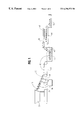
- FIG. 1 is a schematic diagram illustrating the sequence of process steps used in accordance with a preferred embodiment of the present invention
- FIG. 2 is a perspective view illustrating an example of a self-locking nut having an applied plastic patch on its threaded surface and a preferred patch applicator used in the practice of the present invention, with the nut having been rotated 180° after patch application to show the patch location within the nut;
- FIG. 3 is a cross-sectional view taken along line 3 — 3 of FIG. 2;
- FIG. 4 is another cross-sectional view taken along line 4 — 4 of FIG. 3;
- FIG. 5 is a cross-sectional view taken generally along the axial center line of the applicator illustrated in FIG. 2;
- FIGS. 6-10 are illustrations of another preferred embodiment of a patch applicator useful in the practice of the present invention.
- the basic component of the present invention is an internally-threaded fastener fabricated from a metal or metal alloy.
- the fastener has a body 10 with a bore 12 extending to its opposing ends 14 and 16 .
- the body 10 can be fabricated from any well known metal and may, optionally, be plated with zinc, cadmium or other materials to provide anti-corrosion properties or improved aesthetics.
- the bore 12 is threaded along its entire length, with the exception of a short counter sink at each end, thereby forming a threaded surface 18 , terminating with so-called “lead threads” at ends 14 and 16 .
- the locking element is in the form of a patch 20 of thermoplastic material applied and fused to at least a portion of the threaded surface 18 .
- the patch 20 is well defined and generally rectangular in shape, with little or no incidental polymer deposits located outside the main body of patch 20 .
- the lead threads at both ends of the fastener will be substantially free of polymer deposits, facilitating the initial engagement of the fastener with its complimentary mating male fastener.
- plastic materials may be employed in the practice of the present invention. However, a nylon thermoplastic resin has been found particularly useful. For example, nylon 11 supplied by the Morton Powder Division of Rohm and Haas Company under the trade names Corvel 76-5001 or Corvel 76-5004 have been found satisfactory.
- the nylon patch locking element 20 is applied and fused to the threaded surface 18 of the fastener using any of the well known techniques disclosed in the prior art, such as those disclosed in several of the above-listed patents.
- the fastener is preheated, using an induction coil heater and then an air-entrained stream of nylon powder is directed onto its threaded surface 18 .
- the powder thereby melts and forms a generally molten mass on a portion of the threads which, upon cooling, forms a solid plastic patch fused to the threaded surface.
- FIG. 1 One such processing system is illustrated in FIG. 1 .
- the fasteners 10 are fed from a feed bowl 30 down an escapement track 32 , through an induction coil heater 34 and into a spray station having two powder applicators 36 , 38 .
- the first applicator 36 directs a first air-entrained powder stream onto the threaded surface of the fastener
- the second applicator 38 directs a second air-entrained powder stream over the first applied powder. It has been found advantageous to build the patch with multiple, at least two, powder spray applications. This allows better control of patch coating weight, patch definition and increased production.
- the fasteners then proceed onto a conveyor 40 where they are air-cooled for a short time, from about one to five minutes, and then immersed in a conditioning bath 42 .
- the fasteners are cooled, either in ambient air or by passage through a forced-air cooling chamber, to maintain the temperature of the conditioning bath below 212° F.
- Conveyor 44 carries the fasteners through bath 42 and deposits them onto still another conveyor 46 which carries the fasteners through an infrared drying oven 48 and ultimately drops the fasteners into any suitable shipping or storage container 50 .
- the applicator employed to form and direct the air-entrained powder into the fastener is that illustrated in FIGS. 2 and 5.
- the applicator 50 comprises a spray head or nozzle 52 , forming a generally arcuate, radially opening slot which is supplied with a pressurized air stream carrying the air-entrained nylon powder via conduit 54 . While the arcuate extent of the spray nozzle 52 may be varied, it has been found that an arcuate slot in the range of about 60°-75° is preferred, with an arc of about 68° being found optimal.
- a cylinder 56 is mounted concentrically around conduit 54 , the cylinder having a closed end 58 and an open end 60 located immediately adjacent nozzle 52 . These components thereby define a generally annular vacuum nozzle 62 connected to a vacuum source via port 64 .
- the nylon powder may be delivered to the threaded surface 18 of the fastener with the nozzle 52 located at a fixed axial position within bore 12 .
- unexpected advantages have been obtained by applying the powder while the nozzle 52 , together with vacuum nozzle 62 , moves axially within bore 12 .
- the powder is applied while the nozzles 52 and 62 move axially first in one direction and then in the opposite direction along only an interior portion of the bore 12 .
- This powder application technique has been found to substantially reduce the variance in prevailing-torque performance values that otherwise occur with a stationary nozzle, depending upon the angular orientation of the nozzle relative to the start point of the fastener's lead threads.
- FIGS. 6-10 Another applicator mechanism is illustrated in FIGS. 6-10.
- two applicators 62 and 64 are mounted in a base block 66 .
- the applicators each include a central conduit 68 , terminating in a powder spray nozzle 70 with dispensing slot 71 .
- a cylinder 72 is mounted concentrically around conduit 68 and has a radial cut at its free end which forms a vacuum slot 74 when the spray nozzle 70 is mounted over it. Both the spray nozzle slot 71 and the vacuum slot 74 define an arc of about 68°.
- the block 66 includes passageways 76 for transmission of a coolant (as indicated by the arrows) and vacuum ports 78 which communicate with the interior of cylinder 72 .
- the fasteners made in accordance with the present invention achieve the prevailing-torque performance characteristics of both IFI 100/107 (1987) and IFI 101 (1987).
- the ability to meet both the clamp load torque window and minimum removal torques specified in these IFI standards results, in part, from a post patch application treatment which conditions the frictional properties of the nylon patch locking element and the threaded surface of the fastener, as well.
- the fastener with the pre-applied patch is immersed, sprayed or otherwise effectively wetted with a wax containing aqueous emulsion. In the process illustrated schematically in FIG. 1, this conditioning treatment is carried out by immersion of the fasteners in bath 42 .
- a bath comprising an aqueous hydrocarbon wax dispersion
- a hydrocarbon wax dispersion is manufactured under the trade designation OKS 1765 by OKS Specialty Lubricants International GmbH P.O.B. 50 04 66, D-80974 Kunststoff, Germany.
- OKS 1765 by OKS Specialty Lubricants International GmbH P.O.B. 50 04 66, D-80974 Kunststoff, Germany.
- the fasteners are thoroughly wetted with the solution and thereafter dried in any conventional manner.
Abstract
Description
Claims (9)
Priority Applications (13)
| Application Number | Priority Date | Filing Date | Title |
|---|---|---|---|
| US09/460,862 US6296573B1 (en) | 1999-12-14 | 1999-12-14 | Self-locking internally threaded fastener and method of manufacture |
| AT00200479T ATE308685T1 (en) | 1999-12-14 | 2000-02-11 | THREADED FASTENING ELEMENTS AND THEIR PRODUCTION PROCESS |
| EP00200479A EP1108903B1 (en) | 1999-12-14 | 2000-02-11 | Threaded fasteners and their manufacturing method |
| DE60023638T DE60023638T2 (en) | 1999-12-14 | 2000-02-11 | Threaded fasteners and their method of manufacture |
| CA002298179A CA2298179C (en) | 1999-12-14 | 2000-02-11 | Improved self-locking internally threaded fastener and method of manufacture |
| MXPA00012431A MXPA00012431A (en) | 1999-12-14 | 2000-12-14 | Self-locking internally threaded fastener & method of manufacture. |
| JP2000381034A JP2001200828A (en) | 1999-12-14 | 2000-12-14 | Improved automatic lock type fastener with inner side screw and method of manufacturing it |
| AU72306/00A AU776060B2 (en) | 1999-12-14 | 2000-12-14 | Improved self-locking internally threaded fastener and method of manufacture |
| BR0006802-0A BR0006802A (en) | 1999-12-14 | 2000-12-14 | Internally threaded fastener with predominant torque and method to manufacture the same |
| ARP000106655A AR030174A1 (en) | 1999-12-14 | 2000-12-14 | FASTENER WITH IMPROVED INTERNAL ADJUSTABLE THREAD AND MANUFACTURING METHOD |
| KR1020000076532A KR20010062434A (en) | 1999-12-14 | 2000-12-14 | Improved self-locking internally threaded fastener and method of manufacture |
| TW089126799A TW477868B (en) | 1999-12-14 | 2001-01-30 | Improved prevailing-torque internally threaded fastener and method of manufacture |
| US09/924,706 US6454504B2 (en) | 1999-12-14 | 2001-08-08 | Self-locking internally threaded fastener and method of manufacture |
Applications Claiming Priority (1)
| Application Number | Priority Date | Filing Date | Title |
|---|---|---|---|
| US09/460,862 US6296573B1 (en) | 1999-12-14 | 1999-12-14 | Self-locking internally threaded fastener and method of manufacture |
Related Child Applications (1)
| Application Number | Title | Priority Date | Filing Date |
|---|---|---|---|
| US09/924,706 Division US6454504B2 (en) | 1999-12-14 | 2001-08-08 | Self-locking internally threaded fastener and method of manufacture |
Publications (1)
| Publication Number | Publication Date |
|---|---|
| US6296573B1 true US6296573B1 (en) | 2001-10-02 |
Family
ID=23830367
Family Applications (2)
| Application Number | Title | Priority Date | Filing Date |
|---|---|---|---|
| US09/460,862 Expired - Lifetime US6296573B1 (en) | 1999-12-14 | 1999-12-14 | Self-locking internally threaded fastener and method of manufacture |
| US09/924,706 Expired - Lifetime US6454504B2 (en) | 1999-12-14 | 2001-08-08 | Self-locking internally threaded fastener and method of manufacture |
Family Applications After (1)
| Application Number | Title | Priority Date | Filing Date |
|---|---|---|---|
| US09/924,706 Expired - Lifetime US6454504B2 (en) | 1999-12-14 | 2001-08-08 | Self-locking internally threaded fastener and method of manufacture |
Country Status (12)
| Country | Link |
|---|---|
| US (2) | US6296573B1 (en) |
| EP (1) | EP1108903B1 (en) |
| JP (1) | JP2001200828A (en) |
| KR (1) | KR20010062434A (en) |
| AR (1) | AR030174A1 (en) |
| AT (1) | ATE308685T1 (en) |
| AU (1) | AU776060B2 (en) |
| BR (1) | BR0006802A (en) |
| CA (1) | CA2298179C (en) |
| DE (1) | DE60023638T2 (en) |
| MX (1) | MXPA00012431A (en) |
| TW (1) | TW477868B (en) |
Cited By (6)
| Publication number | Priority date | Publication date | Assignee | Title |
|---|---|---|---|---|
| US6648970B1 (en) | 2002-06-24 | 2003-11-18 | Nylok Corporation | Method and apparatus for applying a powdered resin to fasteners |
| US20060070572A1 (en) * | 2003-05-01 | 2006-04-06 | Richard Duffy | Process and apparatus for the application of fluoropolymer coating to threaded fasteners |
| DE102009032990A1 (en) | 2008-08-21 | 2010-02-25 | NMC Group, Inc., Pomona | Male Hybrid Composite Metal Fastener |
| US20100104395A1 (en) * | 2008-08-21 | 2010-04-29 | Robert Stephen | Hybrid composite-metal male fasteners |
| US20160082463A1 (en) * | 2014-09-18 | 2016-03-24 | Nylok Llc | Combined spray and vacuum nozzle |
| CN110333025A (en) * | 2019-07-16 | 2019-10-15 | 中国航发沈阳发动机研究所 | The design method and plug thread gauge of self-locking nut locking torque validation checking tool |
Families Citing this family (5)
| Publication number | Priority date | Publication date | Assignee | Title |
|---|---|---|---|---|
| DE102005025001A1 (en) * | 2005-06-01 | 2006-12-07 | Carl Zeiss Jena Gmbh | Anti-thread-looseness structure for removing play in a pairing of threads positions symmetrically rotational optical elements like lenses in a projector's chassis |
| JP5283051B2 (en) * | 2006-09-19 | 2013-09-04 | 日本発條株式会社 | Loosening prevention nut |
| DE202007004104U1 (en) * | 2007-03-16 | 2007-05-24 | Dorma Gmbh + Co. Kg | Regulating valve for hydraulic door closer has anti-rotation lock on body formed by groove on thread and holding elastic element to eliminate play |
| DE102011119140A1 (en) * | 2011-11-23 | 2013-05-23 | GESI Gewindesicherungs-GmbH | thread Locking |
| DE102018202926A1 (en) * | 2018-02-27 | 2019-08-29 | Aktiebolaget Skf | Actuator with a threaded spindle and plastic element |
Citations (10)
| Publication number | Priority date | Publication date | Assignee | Title |
|---|---|---|---|---|
| US2741288A (en) * | 1950-04-15 | 1956-04-10 | Kenneth L Johnson | Thread root elastic lock means |
| US3294139A (en) * | 1964-06-01 | 1966-12-27 | Elastic Stop Nut Corp | Plastic patch, self-locking threaded fasteners and methods of making such fasteners |
| US3766584A (en) * | 1971-07-30 | 1973-10-23 | Usm Corp | The process of making self-locking threaded inserts |
| US3858262A (en) * | 1972-12-13 | 1975-01-07 | Usm Corp | Method of making self-locking internally threaded articles |
| US4060868A (en) * | 1977-01-17 | 1977-12-06 | Usm Corporation | Powder applying apparatus and process for making self-locking threaded elements |
| US4070724A (en) * | 1974-05-02 | 1978-01-31 | Amerace Corporation | Apparatus for making self-locking internally threaded fasteners with ring-like locking elements |
| US4775555A (en) | 1986-09-15 | 1988-10-04 | Nylok Fastener Corporation | Apparatus and process for making locking nuts |
| US5356254A (en) * | 1992-07-24 | 1994-10-18 | Nylok Fastener Corporation | High temperature self-locking threaded fastener |
| EP0759511A1 (en) | 1995-07-05 | 1997-02-26 | Nylok Fastener Corporation | Improved self-locking fastener, apparatus and method |
| US6095733A (en) * | 1998-06-29 | 2000-08-01 | Huck International, Inc. | Threaded fastener with determinable clamp load |
Family Cites Families (10)
| Publication number | Priority date | Publication date | Assignee | Title |
|---|---|---|---|---|
| US3731724A (en) * | 1971-07-30 | 1973-05-08 | U & M Corp | Self-locking threaded insert |
| US3908727A (en) * | 1972-07-24 | 1975-09-30 | Microdot Inc | Fastener |
| US3894509A (en) | 1973-09-10 | 1975-07-15 | Usm Corp | Apparatus for manufacture of fasteners |
| US3995074A (en) | 1973-09-10 | 1976-11-30 | Usm Corporation | Method for the manufacture of fasteners |
| US4054688A (en) | 1975-04-28 | 1977-10-18 | Usm Corporation | Method of making locking nuts |
| US4100882A (en) | 1976-07-12 | 1978-07-18 | Usm Corporation | Apparatus for making locking nuts |
| US4366190A (en) | 1980-06-26 | 1982-12-28 | Rodden Philip J | Locking patch machine |
| US5221170B1 (en) | 1986-09-15 | 1995-08-01 | Nylok Fastener Corp | Coated threaded fasteners |
| US5141771A (en) | 1989-10-20 | 1992-08-25 | Nylok Fastener Corporation | Method for producing coated fastener samples |
| JP2736149B2 (en) * | 1990-03-23 | 1998-04-02 | 株式会社東芝 | Trend graph scaling device |
-
1999
- 1999-12-14 US US09/460,862 patent/US6296573B1/en not_active Expired - Lifetime
-
2000
- 2000-02-11 DE DE60023638T patent/DE60023638T2/en not_active Expired - Lifetime
- 2000-02-11 CA CA002298179A patent/CA2298179C/en not_active Expired - Lifetime
- 2000-02-11 EP EP00200479A patent/EP1108903B1/en not_active Expired - Lifetime
- 2000-02-11 AT AT00200479T patent/ATE308685T1/en not_active IP Right Cessation
- 2000-12-14 JP JP2000381034A patent/JP2001200828A/en not_active Withdrawn
- 2000-12-14 AU AU72306/00A patent/AU776060B2/en not_active Ceased
- 2000-12-14 BR BR0006802-0A patent/BR0006802A/en not_active Application Discontinuation
- 2000-12-14 MX MXPA00012431A patent/MXPA00012431A/en unknown
- 2000-12-14 KR KR1020000076532A patent/KR20010062434A/en not_active Application Discontinuation
- 2000-12-14 AR ARP000106655A patent/AR030174A1/en unknown
-
2001
- 2001-01-30 TW TW089126799A patent/TW477868B/en not_active IP Right Cessation
- 2001-08-08 US US09/924,706 patent/US6454504B2/en not_active Expired - Lifetime
Patent Citations (11)
| Publication number | Priority date | Publication date | Assignee | Title |
|---|---|---|---|---|
| US2741288A (en) * | 1950-04-15 | 1956-04-10 | Kenneth L Johnson | Thread root elastic lock means |
| US3294139A (en) * | 1964-06-01 | 1966-12-27 | Elastic Stop Nut Corp | Plastic patch, self-locking threaded fasteners and methods of making such fasteners |
| US3766584A (en) * | 1971-07-30 | 1973-10-23 | Usm Corp | The process of making self-locking threaded inserts |
| US3858262A (en) * | 1972-12-13 | 1975-01-07 | Usm Corp | Method of making self-locking internally threaded articles |
| US4070724A (en) * | 1974-05-02 | 1978-01-31 | Amerace Corporation | Apparatus for making self-locking internally threaded fasteners with ring-like locking elements |
| US4060868A (en) * | 1977-01-17 | 1977-12-06 | Usm Corporation | Powder applying apparatus and process for making self-locking threaded elements |
| US4775555A (en) | 1986-09-15 | 1988-10-04 | Nylok Fastener Corporation | Apparatus and process for making locking nuts |
| US5356254A (en) * | 1992-07-24 | 1994-10-18 | Nylok Fastener Corporation | High temperature self-locking threaded fastener |
| US5356254B1 (en) * | 1992-07-24 | 1996-12-10 | Nylok Fastener Co | High temperature self-locking threades fastener |
| EP0759511A1 (en) | 1995-07-05 | 1997-02-26 | Nylok Fastener Corporation | Improved self-locking fastener, apparatus and method |
| US6095733A (en) * | 1998-06-29 | 2000-08-01 | Huck International, Inc. | Threaded fastener with determinable clamp load |
Non-Patent Citations (3)
| Title |
|---|
| Article taken from "Advancing Fastener Application Engineering", Advancements in prevailing-torque locknuts reflected in four IFI stantdard, by James R. Davis, 1969. |
| European Search Report-Application No. 00200479.4. |
| European Search Report—Application No. 00200479.4. |
Cited By (13)
| Publication number | Priority date | Publication date | Assignee | Title |
|---|---|---|---|---|
| US6648970B1 (en) | 2002-06-24 | 2003-11-18 | Nylok Corporation | Method and apparatus for applying a powdered resin to fasteners |
| US20060070572A1 (en) * | 2003-05-01 | 2006-04-06 | Richard Duffy | Process and apparatus for the application of fluoropolymer coating to threaded fasteners |
| US7211147B2 (en) * | 2003-05-01 | 2007-05-01 | Nylok Corporation | Apparatus for the application of fluoropolymer coating to internally threaded fasteners |
| US7896599B2 (en) | 2008-08-21 | 2011-03-01 | Douglas Stephen | Hybrid composite-metal male fastener |
| US20100047034A1 (en) * | 2008-08-21 | 2010-02-25 | Douglas Stephen | Hybrid composite-metal male fastener |
| US20100104395A1 (en) * | 2008-08-21 | 2010-04-29 | Robert Stephen | Hybrid composite-metal male fasteners |
| DE102009032990A1 (en) | 2008-08-21 | 2010-02-25 | NMC Group, Inc., Pomona | Male Hybrid Composite Metal Fastener |
| US8105004B2 (en) | 2008-08-21 | 2012-01-31 | Robert Stephen | Hybrid composite-metal male fasteners |
| DE102010055732A1 (en) | 2009-12-22 | 2011-07-07 | NYLON MOLDING CORPORATION, Calif. | Male Hybrid Composite Metal Fasteners |
| US20160082463A1 (en) * | 2014-09-18 | 2016-03-24 | Nylok Llc | Combined spray and vacuum nozzle |
| US10792689B2 (en) * | 2014-09-18 | 2020-10-06 | Nylok Llc | Combined spray and vacuum nozzle |
| CN110333025A (en) * | 2019-07-16 | 2019-10-15 | 中国航发沈阳发动机研究所 | The design method and plug thread gauge of self-locking nut locking torque validation checking tool |
| CN110333025B (en) * | 2019-07-16 | 2021-04-16 | 中国航发沈阳发动机研究所 | Design method of tool for detecting effectiveness of locking torque of self-locking nut and thread plug gauge |
Also Published As
| Publication number | Publication date |
|---|---|
| EP1108903B1 (en) | 2005-11-02 |
| AR030174A1 (en) | 2003-08-13 |
| KR20010062434A (en) | 2001-07-07 |
| DE60023638T2 (en) | 2006-08-10 |
| DE60023638D1 (en) | 2005-12-08 |
| US6454504B2 (en) | 2002-09-24 |
| ATE308685T1 (en) | 2005-11-15 |
| BR0006802A (en) | 2001-07-31 |
| US20010046428A1 (en) | 2001-11-29 |
| TW477868B (en) | 2002-03-01 |
| AU776060B2 (en) | 2004-08-26 |
| EP1108903A1 (en) | 2001-06-20 |
| CA2298179C (en) | 2004-04-20 |
| AU7230600A (en) | 2001-06-21 |
| JP2001200828A (en) | 2001-07-27 |
| MXPA00012431A (en) | 2005-07-25 |
| CA2298179A1 (en) | 2001-06-14 |
Similar Documents
| Publication | Publication Date | Title |
|---|---|---|
| US6296573B1 (en) | Self-locking internally threaded fastener and method of manufacture | |
| US5221170A (en) | Coated threaded fasteners | |
| US4657460A (en) | Self-bonding threaded fasteners and method of curing same | |
| US5122020A (en) | Self locking fastener | |
| US3568746A (en) | Self-locking threaded fastener | |
| US3787222A (en) | Method of making self-locking threaded element with locking patch effective over a wide range of clearances | |
| US3831213A (en) | Composite self-locking fastener | |
| JPS63214372A (en) | Device and method of manufacturing coated clamping tool | |
| US6156392A (en) | Process for triboelectric application of a fluoropolymer coating to a threaded fastener | |
| IL28948A (en) | Self-locking fastener and method of making it | |
| US5356254A (en) | High temperature self-locking threaded fastener | |
| US4207832A (en) | Notched applicator wheel | |
| US4282913A (en) | Self-locking nut and manufacture and component therefor | |
| DE3600186C2 (en) | Self-locking agent | |
| US4060116A (en) | Method for producing self-locking fasteners | |
| US4046106A (en) | Apparatus and method of forming self-locking fastener | |
| US4357726A (en) | Method of making self-locking nut | |
| US3975787A (en) | Method for making self-locking internally threaded fasteners with ring-like self-locking elements | |
| JP2021110458A (en) | Conductively coated fastening systems for full size determinant assembly (fsda) | |
| US4035859A (en) | Apparatus for making self-locking internally threaded fasteners with ring-like locking elements | |
| US4353941A (en) | Apparatus and method of forming self-locking fastener | |
| US4023224A (en) | Method for producing self-locking fasteners | |
| CA3045870A1 (en) | Threaded fastener with hybrid patch | |
| US4070724A (en) | Apparatus for making self-locking internally threaded fasteners with ring-like locking elements | |
| JPS61290224A (en) | Locking screw |
Legal Events
| Date | Code | Title | Description |
|---|---|---|---|
| AS | Assignment |
Owner name: NYLOK FASTENER CORPORATION, MICHIGAN Free format text: ASSIGNMENT OF ASSIGNORS INTEREST;ASSIGNORS:DUFFY, RICHARD J.;SESSA, EUGENE D.;REEL/FRAME:010612/0125 Effective date: 20000207 |
|
| STCF | Information on status: patent grant |
Free format text: PATENTED CASE |
|
| FPAY | Fee payment |
Year of fee payment: 4 |
|
| REMI | Maintenance fee reminder mailed | ||
| FPAY | Fee payment |
Year of fee payment: 8 |
|
| SULP | Surcharge for late payment |
Year of fee payment: 7 |
|
| FEPP | Fee payment procedure |
Free format text: PAYOR NUMBER ASSIGNED (ORIGINAL EVENT CODE: ASPN); ENTITY STATUS OF PATENT OWNER: LARGE ENTITY |
|
| FPAY | Fee payment |
Year of fee payment: 12 |
|
| AS | Assignment |
Owner name: NYLOK CORPORATION, MICHIGAN Free format text: CHANGE OF NAME;ASSIGNOR:NYLOK FASTENER CORPORATION;REEL/FRAME:036051/0694 Effective date: 20020501 |
|
| AS | Assignment |
Owner name: NYLOK LLC, MICHIGAN Free format text: MERGER;ASSIGNOR:NYLOK CORPORATION;REEL/FRAME:036082/0210 Effective date: 20091222 |