US6301227B1 - Systems and methods for allowing transmission systems to effectively respond to automated test procedures - Google Patents
Systems and methods for allowing transmission systems to effectively respond to automated test procedures Download PDFInfo
- Publication number
- US6301227B1 US6301227B1 US09/139,010 US13901098A US6301227B1 US 6301227 B1 US6301227 B1 US 6301227B1 US 13901098 A US13901098 A US 13901098A US 6301227 B1 US6301227 B1 US 6301227B1
- Authority
- US
- United States
- Prior art keywords
- status
- communication set
- transmission line
- connection status
- cot
- Prior art date
- Legal status (The legal status is an assumption and is not a legal conclusion. Google has not performed a legal analysis and makes no representation as to the accuracy of the status listed.)
- Expired - Fee Related
Links
Images


Classifications
-
- H—ELECTRICITY
- H04—ELECTRIC COMMUNICATION TECHNIQUE
- H04M—TELEPHONIC COMMUNICATION
- H04M3/00—Automatic or semi-automatic exchanges
- H04M3/22—Arrangements for supervision, monitoring or testing
- H04M3/26—Arrangements for supervision, monitoring or testing with means for applying test signals or for measuring
- H04M3/28—Automatic routine testing ; Fault testing; Installation testing; Test methods, test equipment or test arrangements therefor
- H04M3/30—Automatic routine testing ; Fault testing; Installation testing; Test methods, test equipment or test arrangements therefor for subscriber's lines, for the local loop
- H04M3/301—Circuit arrangements at the subscriber's side of the line
Definitions
- the present invention generally relates to telecommunication test systems and methods, and more particularly to telecommunication tests and methods that allow transmission systems, such as Subscriber Line Multiplexer Systems to effectively respond to automatic test procedures, such as the MLT (Mechanized Loop Test).
- a Subscriber Line Multiplexer system is a type of transmission system that uses digitally multiplexed channels to connect two or more telephone subscribers to a central office.
- This system uses the ISDN U-interface technology, or xDSL technologies, such as HDSL (High Data Rate Subscriber Line), ADSL (Asymmetric Digital Subscriber Line) and their variations, to multiplex several voice and/or data channels over a single copper pair, in order to provide additional virtual telephone or data lines to one or more subscribers over the existing cable facilities.
- xDSL technologies such as HDSL (High Data Rate Subscriber Line), ADSL (Asymmetric Digital Subscriber Line) and their variations, to multiplex several voice and/or data channels over a single copper pair, in order to provide additional virtual telephone or data lines to one or more subscribers over the existing cable facilities.
- the telephone line tests are automated, and one of the most popular automated tests is known as the MLT procedure performed by an MLT system.
- MLT procedure the MLT system applies known electrical signals on the subscriber's loop comprising the telephone line and the subscriber's telephone set and makes appropriate measurements. Based on the measurements, the MLT system can calculate the loop impedance, the parasitic impedances, as well as possible foreign voltages (i.e., voltages other than those supplied from the central office) present on the line.
- the MLT system reports back to the central office the results of the measurements, as well as the probable status of the line. The operator needs to know these results in order to understand the problems and take appropriate actions.
- the impedance between wires of a telephone line may become very low.
- the transmission characteristics of the telephone line may become very poor, and the quality of the services could thus be impaired.
- the presence of a foreign voltage due to, e.g., induction from defective high power electrical ducts can impair the transmission characteristics of the telephone line and can even make it dangerous to use the telephone.
- the MLT procedure is most effective for remote testing telephone lines without having any transmission system, such as a fiber optic transmission system, or a Subscriber Line Multiplexer System connected to the lines. If the subscriber's telephone set is not directly connected to the central office, but instead it is connected through a transmission system, the MLT system does not have direct access to the line. In such a case, when the transmission system detects the presence of an MLT signal, it feeds back to the MLT system the values of three resistors located at the subscriber's loop which represent the “signature” of the current state of the system. These three resistors are respectively connected between the ring and tip lines, the ring line and ground and the tip line and ground.
- the transmission system In order to present the proper signature to the MLT system, the transmission system must perform a series of self tests. If the number of lines serviced by the system is large, the remote equipment can be provided with a rather complex test head for performing elaborate tests of the subscriber's drop (i.e., the copper pair that connects the remote terminal to the subscriber). The test head can report back the results to the central office terminal for presenting the proper signatures. Because large number of lines are serviced, the per-line cost of the test head is relatively small. However, in the case of multiplexer systems with small number of lines, e.g., 2 or 4 lines, the per-line cost of the test head is very high. One solution would be to use a less sophisticated test head with simple self-test circuits.
- the system periodically performs (or at a time when the MLT is detected) simple tests which will establish signatures for presenting to the MLT system.
- simple tests which will establish signatures for presenting to the MLT system.
- the number of tests and the accuracy of the results obtained with these simple circuits are insufficient for detecting the problems of the telephone lines.
- complex circuits have to be used, which dramatically increases the cost.
- This invention provides a cost-effective system and method for testing telephone lines connected to transmission systems, such as Subscriber Line Multiplexer systems.
- transmission systems such as Subscriber Line Multiplexer systems.
- the information returned by the multiplexer system is maximized when MLTs are run by the operating personnel for maintenance or failure detection purposes.
- the invention uses the same pair of wires for transmission and test.
- a system for allowing a test procedure to be performed on a communication system has a transmission line for connecting to telephone exchange and a subscriber line for connecting to a communication set.
- the system of the invention comprises a detector, coupled to the transmission line, for detecting test signals on the transmission line; a bypass circuit, coupled between the transmission and subscriber lines, for allowing the test signals to bypass the communication system; a discriminator, coupled to the subscriber line, for discriminating a connection status of the communication set; and a controller, coupled to the detector, the discriminator and the bypass circuit, for activating, in accordance with detection of the test signals and the connection status of the communication set, the bypass circuit so as to allow the test signals to bypass the communication system and connect to the communication set and perform measurements.
- the system of invention additionally includes a status circuit, coupled to the controller, for reproducing, upon discriminating a predetermined connection status of the communication set, the predetermined connection status of the communication set for presenting to the test signals.
- the predetermined connection status includes off-hook and short statuses of the communication set.
- the status circuit reproduces the predetermined connection status by emulating an impedance of a loop comprising the subscriber line and the communication set.
- the status circuit emulates a linear impedance if the connection status discriminated by the discriminator indicates a short status and a non-linear impedance if the connection status discriminated indicates an off-hook status.
- the communication system includes a second transmission line for connecting to the telephone exchange and a second subscriber line for connecting to a second communication set.
- the first transmission line transmits signals to the first subscriber line and the second transmission line transmits signals to the second subscriber line.
- the controller activates the bypass circuit in accordance with the connection statuses of both the communcation sets.
- the system of the invention additionally includes a signature generator, coupled to the first and second transmission lines, for generating a signature, indicative of the communication system status, on one of the transmission lines on which the test signals are detected.
- FIG. 1 shows an overall block diagram of a 2-line subscriber line multiplexer system according to an embodiment of the invention
- FIG. 2 shows a detailed diagram of a line card (LC) according to an embodiment of the invention
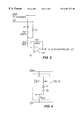
- FIG. 3 shows the schematic diagram of an MLT detector according to an embodiment of the invention
- FIG. 4 shows the schematic diagram of a line status circuit according to an embodiment of the invention
- FIG. 5 illustrates a detailed diagram of a remote terminal according to an embodiment of the invention.
- FIG. 6 shows an alternative embodiment of a ROH discriminator according to an embodiment of the invention.
- FIG. 1 shows an overall block diagram of a 2-line subscriber line multiplexer system according to one embodiment of the invention. It should be understood that the invention also applies to a multiplexer system with any number of lines.
- multiplexer system includes two terminals, a central office terminal (COT) 100 and a remote terminal (RT) 200 .
- COT 100 is installed in a central office (CO) and includes at least one line card (LC) 110 .
- LC 110 comprises MLT detectors 120 and 122 , LC circuitry 126 , line status circuits 130 and 132 , signature generation circuit 136 , and 2-pole line bypass relays K 1 , K 2 and K 3 .
- Analog lines from a telephone exchange (not shown) are connected to the analog inputs of COT 100 , i.e., lines 1 and 2 .
- An MLT system (not shown) is connected to the analog inputs of COT 100 via the telephone exchange.
- bypass relays K 1 , K 2 and K 3 in LC 110 are controlled by a microcontroller in LC circuitry 126 .
- relay K 1 connects line 1 to bypass bus 128 ;
- relay K 2 connects line 2 to bypass bus 128 ;
- relay K 3 connects bypass bus 128 to a telephone line 160 , known as DSL (Digital Subscriber Line) and disconnects the DSL from LC circuitry 126 .
- DSL Digital Subscriber Line
- an appropriate relay (K 1 or K 2 ) is operated, so that signature generator circuit 136 is connected to the bypass bus 128 without activating K 3 .
- Signature generation circuit 136 is connected to bypass bus 128 by the internal relays of signature generation circuit 136 . These internal relays are controlled by the microcontroller in LC circuitry 126 .
- RT 200 is connected to COT 100 through DSL 160 .
- RT 200 comprises a RT circuitry 210 , ROH discriminators 220 and 230 , a 1-pole DSL bypass relay K 4 , 2-pole line bypass relays K 5 and K 6 and a 2-pole latching relay K 7 .
- Communication sets such as telephone sets (not shown) are connected to RT 200 at its analog inputs, i.e., lines 1 and 2 .
- each of telephone lines 1 and 2 and DSL 160 includes a pair of analog lines, i.e., ring and tip lines, as will be illustrated in more detail later.
- bypass relays K 4 , K 5 and K 6 and latching relay K 7 are controlled by a microcontroller in RT circuitry 210 .
- Bypass relay K 4 when operated, connects DSL 160 to bypass bus 240 .
- Bypass relays K 5 and K 6 when operated, can respectively connect lines 1 and 2 to bypass bus 240 .
- Latching relay K 7 switches between lines 1 and 2 for connecting to DSL 160 .
- lines 1 and 2 are connected to subscribers via LC circuitry 126 and RT circuitry 210 , and communications among the subscribers are as usual.
- one of MLT detectors 120 and 122 detects the MLT signals and reports the detection to the microcontroller in LC circuitry 126 . If the multiplexer system is in good operating condition, with all the telephone sets at the subscriber's end being on hook, LC circuitry 126 sends a message to the microcontroller in RT circuitry 210 in RT 200 to request the telephone line under test to go into a bypass state. Upon receiving the message, the microcontroller in RT 200 switches latching relay K 7 on the position that corresponds to the requested line and sends an acknowledge message back to LC 110 .
- the microcontroller in LC circuitry 126 After receiving the acknowledgment message from RT 200 , the microcontroller in LC circuitry 126 causes selected relays in LC 110 to go into a bypass state so as to connect the line under test to a corresponding bypass bus 128 or 129 . In this way, the MLT system is directly connected to the subscriber's premises through DSL 160 and various tests can thus be performed to detect faults.
- RT circuitry 210 is provided with a SLIC (Subscriber Line Interface Circuit) (not shown) on each telephone line.
- SLIC Subscriber Line Interface Circuit
- the SLIC reports to the local microcontroller in RT circuitry 210 whether there is a current flowing through the loop on the associated line. If no current is detected, it indicates that either the telephone receiver is on hook or the subscriber's drop is interrupted. In such case, when an MLT signal comes on the line, the multiplexer system will go into bypass state at both LC 110 and RT 200 so that the MLT signal can make measurements and detect whether a telephone set is present (on hook) or whether the subscriber's drop is interrupted.
- an associated ROH discriminator 220 or 230 will measure the loop impedance and report the measurement to the local microcontroller in RT circuitry 210 .
- the local microcontroller reports back the measured loop impedance to the microcontroller in LC circuitry 126 , which will configure an associated line status circuit 130 or 132 to emulate the measured impedance at LC 110 .
- the emulated impedance will be linear in case of a short or nonlinear in case of a ROH(the telephone impedance when its receiver is off hook).
- the MLT signal will measure the emulated impedance and reports back the proper result (short or ROH) to the MLT system.
- This emulated impedance represents the status of the line under test.
- the telephone company may follow up with necessary repairs on the line. The details will be described later.
- RT 200 In the case where RT 200 is remotely powered, it loses power when LC 110 goes into bypass state. This causes bypass relays K 4 , K 5 and K 6 to switch to the bypass positions, while latching relay K 7 remains at the position before the power was down and operates to select the line for bypassing.
- signature generation circuit 136 will present an appropriate signature, i.e., a set of electrical signals, to the MLT system, indicating the system status, as will be described in detail below.
- FIGS. 2, 3 and 4 are next described.
- FIG. 2 shows a detailed diagram of LC 110 .
- FIGS. 3 and 4 show, respectively, the schematic diagrams of the MLT detector 120 , 122 and the line status circuit 130 , 132 illustrated in FIG. 2 .
- signature generation circuit 136 uses four relays Ka 2 , Ka 3 , Ka 4 and Ka 5 to select a desired signature (a group of three resistors).
- Relay Ka 1 is used to connect the signature to bypass bus 128 , as described above.
- Signature generation circuit 136 is designed to accommodate the applicable signatures standardized by the Bellcore TR-909 recommendation. The resistor values in circuit 136 are those specified by this recommendation and are tabulated in Table 1 below.
- each MLT detector comprises a buffer 123 , two diodes D 1 and D 2 , and three resistors Rd 1 , Rd 2 and Rd 3 .
- Diodes D 1 and D 2 are used to bias the relative polarities of the ring and tip leads.
- the associated MLT detector measures the voltage across the ring and tip lines of the telephone line under test. If the voltage value is within a predetermined range, e.g., ⁇ 5V, buffer 123 outputs an MLT detection signal to microcontroller 127 in LC circuitry 126 to indicate that an MLT signal has been detected on the line.
- the multiplexer system is in good operating condition as detected by its detectors and a signaling transmission channel (both of which are not shown), and if an MLT signal is detected on one line, then whether the MLT system has fill access to the line under test depends on the connection statuses of the telephone sets connected to the two lines.
- microcontroller 127 in LC circuitry 126 will send a message to the microcontroller in RT 200 to request the telephone line under test to go into a bypass state.
- the system will go into a bypass state and the MLT system will have full access down to the subscriber's end on the line under test and be able to make necessary measurements, as described in the above.
- the multiplexer system will, through signature generation circuit 136 , apply a signature “System Busy” on the line under test. In this case, no MLT procedure is performed in order not to disturb communication on the other busy line.
- the subscriber loop at the COT is closed and the system does not do anything in response to detection of an MLT signal.
- the associated ROH discriminator discriminates whether the off-hook status is due to a real ROH or a short since the SLIC does not differentiate between the two conditions.
- the ROH discriminator informs the microcontroller in the LC of the discriminated connection status and then the microcontroller configures an associated line status circuit at LC 110 to emulate either the ROH or short impedance, as the case may be. This will allow the MLT signal to measure the emulated impedance and report to the MLT system the appropriate status of the line under test.
- the system will do nothing.
- the MLT system will be allowed to measure the line up to the failure point, and detect the nature and location of the failure. If the MLT signal comes on the other line instead, signature generation circuit 136 will generate an appropriate signature and the MLT system will display a message “Bad DSL”, which is also provided for under a different name by Bellcore TR-909 specifications.
- the signature generation circuit will generate an appropriate signature and the MLT system will display a message “Bad RT” or “Bad COT” to indicate where the failure is located.
- the signature generation circuit will generate an appropriate signature and the MLT system will display a message “System busy, try later”.
- each of lines 1 and 2 can be connected to signature generation circuit 136 by activating selected bypass relays, so that a signature can be generated and presented on the appropriate line.
- a signature generated by generation circuit 136 complies with Bellcore TR-909 specifications and includes a set of impedance values. These impedance values include the impedance between the tip line and the ground RTG, the impedance between the ring line and the ground RRG, and the impedance between the tip line and ring line RTG. Table 2 shows a summary of various signatures generated by the system in response to MLT signals under different circumstances.
- FIG. 4 shows a detailed diagram of the line status circuit 130 , 132 .
- the MLT status circuit comprises a resistor Rp 1 connected in series with zener diodes Z 1 and Z 2 .
- the series combination of Rp 1 , Z 1 and Z 2 is connected to resistor Rp 2 in parallel.
- a relay KROH is connected to the parallel circuit.
- the line status circuit reproduces the status of the line under test as discriminated by an associated ROH discriminator 220 or 230 . Detection of the line status by the ROH discriminator will be described in connection with FIGS. 5 and 6.
- microcontroller 127 When a ROH discriminator discriminates the status of the line under test as short and reports back to LC 110 , microcontroller 127 operates KROH to cause the MLT system to connect to resistor Rp 2 . Thus, the MLT system will measure a linear resistance Rp 2 between tip and ring lines, and will display a message indicating a probable short.
- microcontroller 127 operates KROH to cause the MLT system to connect to the series combination of resistor Rp 1 , and zener diodes Z 1 and Z 2 . Therefore, the MLT system will measure a nonlinear impedance between tip and ring lines, which is a characteristic of an off-hook telephone. The MLT system will display the message “ROH”.
- bypass relays are in the positions that would not cause the system to be bypassed.
- FIG. 5 illustrates RT 200 in more detail.
- each of ROH discriminators 220 and 230 comprises the same components and both operate in the similar manner.
- latching relay K 7 is switched by microcontroller 212 to connect the ring and tip lines of line 1 to bypass bus 240 .
- Microcontroller 212 also causes a current to be provided from SLIC (Subscriber Line Interface Circuit) 214 , e.g., Erricsson SLIC, to an associated ROH discriminator 220 .
- SLIC Subscriber Line Interface Circuit
- ROH discriminator 220 comprises a buffer 222 which functions as an amplifier with balanced input impedance, a comparator 223 with hysteresis and a plurality of resistors.
- SLIC 214 delivers a constant current to the loop comprising line 1 and the telephone.
- the line voltage of line 1 amplified by buffer 222 is proportional to the line resistance and is fed to comparator 223 .
- Comparator 223 compares the line voltage with a predetermined reference value Vref The reference voltage Vref corresponds to a line resistance of 200 ohms. Therefore, if the output of the comparator indicates that the line voltage is greater than Vref, this indicates that the line resistance is greater than 200 ohms.
- the line impedance without having a telephone set connected should less than 100 ohms for line multiplexers.
- the telephone impedance is generally greater than 450 ohms.
- a 200 ohm threshold makes a good differentiation between a short and a ROH (receiver off-hook).
- the line impedance is greater than 200 ohms, it indicates a ROH, but if the line impedance is less than 200 ohms, it indicates a short.
- the SLIC will report the status of the telephone as on hook.
- the comparator output is polled by microcontroller 212 , and an appropriate message is sent to COT 100 indicating the status of the line based on the comparator output.
- FIG. 6 shows an alternative and more accurate embodiment of the ROH discriminator.
- the ROH discriminator comprises a current generation circuit 302 , a SLIC 304 , an analog-to-converter (A/D) converter 306 , an amplifier buffer 310 and resistors Ra to Rd.
- Current generation circuit 302 includes resistors RDC 1 , RDC 2 and RDCA and a transistor Q.
- the gate electrode of transistor Q is coupled to microcontroller 212 . By turning the transistor on and off, two different currents may be applied to the subscriber's loop comprising the telephone line and the telephone.
- the line voltage between the ring and tip lines is amplified by buffer 310 .
- the amplified line voltage is provided to A/D converter 306 , which can be read by the microcontroller, via the data bus, to obtain the digital value of the line voltage.
- the line impedance By measuring the line voltage and thus the line impedance for two different currents, it is possible to determine whether the line impedance is linear (i.e., shorted line) or non-linear (i.e., ROH). Specifically, if the line impedance RL, as measured, is in the range of 200-600 ohms and the two measured values of RL are different by more than 15%, then ROH is indicated. if RL, as measured, is less than 200 ohms, the assumption is that the line is shorted.
- the line status circuit emulates the line impedance only when the telephone is off hook or shorted. In the on hook situation, the impedance is not emulated.
Abstract
Description
| TABLE 1 |
| Resistance values in |
| Resistor | Resistance value (in ohms) | ||
| R1 | 295k | ||
| R2 | 175k | ||
| R3 | 175k | ||
| R4 | 130k | ||
| R5 | 70k | ||
| R6 | 70k | ||
| R7 | 19.8k | ||
| R8 | 189.1k | ||
| R9 | 189.1k | ||
| R10 | 17.8k | ||
| R11 | 296.1k | ||
| R12 | 296.1k | ||
| TABLE 2 |
| Summary of Various Signatures in Different Situations |
| Signature Generated | ||||||||
| in Response to an | ||||||||
| Connection | MLT Signal Detected | Relays | ||||||
| LC | RT | Line | Status | on the Line | Operated | RTG | RRG | |
| Good | Good | |||||||
| 1 | On-hook | Generate Signature | Ka1, | 175k | 175k | 295k | ||
| “System Busy, Try | Ka2, K3 | |||||||
| Again Later” | ||||||||
| 2 | Off-hook | None | K3 | Open | Open | Emulated | ||
| Nonlinea | ||||||||
| r at | ||||||||
| Bad | Good | |||||||
| 1 | Any | Generate Signature | Ka1, | 110k | 110k | 17.8k | ||
| “COT Failure” | Ka5, |
|||||||
| 2 | Any | Generate Signature | K8, K9, | 110k | 110k | 17.8k | ||
| “COT Failure” | Ka1, | |||||||
| Ka5, | ||||||||
| Good | Bad | |||||||
| 1 | Any | Generate Signature | Ka1, | 90.9k | 90.9k | 17.8k | ||
| “RT Equipment | Ka2, | |||||||
| Failure” | Ka4, |
|||||||
| 2 | Any | Generate Signature | K8, K9, | 90.9k | 90.9k | 17.8k | ||
| “RT Equipment | Ka1, | |||||||
| Failure” | Ka2, | |||||||
| Ka4, K3 | ||||||||
| Good | Not | 1 | Any | None | None | MLT | MLT | MLT |
| pre- | 2 | Any | Generate Signature | K1, K2, | 50k | 50k | 130k | |
| sent | “CPE Not | Ka3 | ||||||
| Provisioned” or | ||||||||
| “Subscriber Channel | ||||||||
| Unit Missing” | ||||||||
Claims (41)
Priority Applications (1)
| Application Number | Priority Date | Filing Date | Title |
|---|---|---|---|
| US09/139,010 US6301227B1 (en) | 1998-08-24 | 1998-08-24 | Systems and methods for allowing transmission systems to effectively respond to automated test procedures |
Applications Claiming Priority (1)
| Application Number | Priority Date | Filing Date | Title |
|---|---|---|---|
| US09/139,010 US6301227B1 (en) | 1998-08-24 | 1998-08-24 | Systems and methods for allowing transmission systems to effectively respond to automated test procedures |
Publications (1)
| Publication Number | Publication Date |
|---|---|
| US6301227B1 true US6301227B1 (en) | 2001-10-09 |
Family
ID=22484719
Family Applications (1)
| Application Number | Title | Priority Date | Filing Date |
|---|---|---|---|
| US09/139,010 Expired - Fee Related US6301227B1 (en) | 1998-08-24 | 1998-08-24 | Systems and methods for allowing transmission systems to effectively respond to automated test procedures |
Country Status (1)
| Country | Link |
|---|---|
| US (1) | US6301227B1 (en) |
Cited By (12)
| Publication number | Priority date | Publication date | Assignee | Title |
|---|---|---|---|---|
| US20020064150A1 (en) * | 2000-09-06 | 2002-05-30 | Pines Philip J. | System and method for diagnosing a POTS port |
| WO2002100078A1 (en) * | 2001-05-31 | 2002-12-12 | Mphase Technologies, Inc. | Bypass for telephone system splitter |
| US6496566B1 (en) * | 2000-09-29 | 2002-12-17 | Lucent Technologies Inc. | Metallic testing of a subscriber loop that provides both voice and digital subscriber line services |
| US6532216B1 (en) * | 1999-09-30 | 2003-03-11 | Bellsouth Intellectual Property Corporation | Central office based ADSL test platform |
| US6535580B1 (en) * | 1999-07-27 | 2003-03-18 | Agere Systems Inc. | Signature device for home phoneline network devices |
| US20030223375A1 (en) * | 2000-01-03 | 2003-12-04 | Dael Govreen-Segal | Apparatus and method for shared line testing |
| US20040165718A1 (en) * | 2003-02-24 | 2004-08-26 | Ramey Blaine Edward | Device and method for detecting presence of service on telephone line |
| US6873685B2 (en) * | 2000-05-17 | 2005-03-29 | Sunrise Telecom Incorporated | Digital subscriber line access and network testing multiplexer |
| US7068758B1 (en) * | 2000-10-23 | 2006-06-27 | Alcatel Canada Inc. | Integrated metallic access for high port density DSLAM |
| US20080043930A1 (en) * | 2004-10-05 | 2008-02-21 | Menny Sherman | Method and System for Distance Measurements |
| US7958267B1 (en) | 2002-11-19 | 2011-06-07 | Quadrus Corporation | Message traffic interception system |
| EP2279607A4 (en) * | 2008-04-22 | 2016-06-15 | Actelis Networks Inc | Automatic telephone line loop around system and method |
Citations (4)
| Publication number | Priority date | Publication date | Assignee | Title |
|---|---|---|---|---|
| US5054050A (en) * | 1990-04-30 | 1991-10-01 | American Telephone & Telegraph Co. | Drop testing in fiber to the home systems |
| US5208803A (en) * | 1990-11-19 | 1993-05-04 | Ag Communication Systems Corporation | Circuit for testing digital lines |
| US5301050A (en) * | 1991-07-30 | 1994-04-05 | Alcatel Network Systems, Inc. | Subscriber loop testing in a fiber-to-the-curb communications network |
| US5712898A (en) * | 1993-03-08 | 1998-01-27 | Adtran, Inc. | D4 channel bank with multi-mode formatted, performance-monitoring communication bus |
-
1998
- 1998-08-24 US US09/139,010 patent/US6301227B1/en not_active Expired - Fee Related
Patent Citations (4)
| Publication number | Priority date | Publication date | Assignee | Title |
|---|---|---|---|---|
| US5054050A (en) * | 1990-04-30 | 1991-10-01 | American Telephone & Telegraph Co. | Drop testing in fiber to the home systems |
| US5208803A (en) * | 1990-11-19 | 1993-05-04 | Ag Communication Systems Corporation | Circuit for testing digital lines |
| US5301050A (en) * | 1991-07-30 | 1994-04-05 | Alcatel Network Systems, Inc. | Subscriber loop testing in a fiber-to-the-curb communications network |
| US5712898A (en) * | 1993-03-08 | 1998-01-27 | Adtran, Inc. | D4 channel bank with multi-mode formatted, performance-monitoring communication bus |
Cited By (16)
| Publication number | Priority date | Publication date | Assignee | Title |
|---|---|---|---|---|
| US6535580B1 (en) * | 1999-07-27 | 2003-03-18 | Agere Systems Inc. | Signature device for home phoneline network devices |
| US6532216B1 (en) * | 1999-09-30 | 2003-03-11 | Bellsouth Intellectual Property Corporation | Central office based ADSL test platform |
| US20030223375A1 (en) * | 2000-01-03 | 2003-12-04 | Dael Govreen-Segal | Apparatus and method for shared line testing |
| US6873685B2 (en) * | 2000-05-17 | 2005-03-29 | Sunrise Telecom Incorporated | Digital subscriber line access and network testing multiplexer |
| US7116637B2 (en) * | 2000-09-06 | 2006-10-03 | Verso Technologies, Inc. | System and method for diagnosing a POTS port |
| US20020064150A1 (en) * | 2000-09-06 | 2002-05-30 | Pines Philip J. | System and method for diagnosing a POTS port |
| US6496566B1 (en) * | 2000-09-29 | 2002-12-17 | Lucent Technologies Inc. | Metallic testing of a subscriber loop that provides both voice and digital subscriber line services |
| US7068758B1 (en) * | 2000-10-23 | 2006-06-27 | Alcatel Canada Inc. | Integrated metallic access for high port density DSLAM |
| US6535581B2 (en) * | 2001-05-31 | 2003-03-18 | Mphase Technologies | Bypass for telephone system splitter |
| WO2002100078A1 (en) * | 2001-05-31 | 2002-12-12 | Mphase Technologies, Inc. | Bypass for telephone system splitter |
| US7958267B1 (en) | 2002-11-19 | 2011-06-07 | Quadrus Corporation | Message traffic interception system |
| US20040165718A1 (en) * | 2003-02-24 | 2004-08-26 | Ramey Blaine Edward | Device and method for detecting presence of service on telephone line |
| US7184544B2 (en) | 2003-02-24 | 2007-02-27 | Thomson Licensing | Device and method for detecting presence of service on telephone line |
| US20080043930A1 (en) * | 2004-10-05 | 2008-02-21 | Menny Sherman | Method and System for Distance Measurements |
| US7664232B2 (en) * | 2004-10-05 | 2010-02-16 | Rit Technologies Ltd. | Method and system for distance measurements |
| EP2279607A4 (en) * | 2008-04-22 | 2016-06-15 | Actelis Networks Inc | Automatic telephone line loop around system and method |
Similar Documents
| Publication | Publication Date | Title |
|---|---|---|
| US5195124A (en) | Testing system for local subscribers | |
| US5361293A (en) | Line/drop testing from a craft terminal using test unit | |
| US7149285B2 (en) | Dynamic, automated double-ended system and method for testing and qualifying metallic telecommunication loops | |
| US20030179859A1 (en) | Method and apparatus for generating an audible tone in DSL environment | |
| US6301227B1 (en) | Systems and methods for allowing transmission systems to effectively respond to automated test procedures | |
| EP0168410B1 (en) | An improved maintenance termination unit | |
| JP3286418B2 (en) | Subscriber line test equipment | |
| EP1802089A1 (en) | DSL line testing with a sealing current | |
| US7760657B1 (en) | System and method for performing subscriber loop testing in an optical network | |
| US4551671A (en) | Terminal disconnect and media wire fault detect mechanism | |
| US7076030B2 (en) | Method and system for testing XDSL wiring | |
| US4373121A (en) | Maintenance termination device | |
| WO2009000120A1 (en) | A narrow-band subscriber board bearing test function and a method for automatic test of subscriber line | |
| US6870903B2 (en) | Method and apparatus for self-testing a customer services terminal and for loop testing telephone lines that are connected thereto | |
| US5115462A (en) | Remotely controlled apparatus for conditioning telephone line exclusive of metallic DC bypass pair | |
| US6754309B2 (en) | Communication device and access network device | |
| US5345496A (en) | Remote line test facility | |
| EP2291988B1 (en) | Crossover faults detection in two-wires network | |
| US6292540B1 (en) | Battery injection and loop supervision for DSL environment | |
| US6856672B2 (en) | Graphic user interface method and apparatus for testing a customer services terminal and a plurality of telephone lines that are connected thereto | |
| US20020145548A1 (en) | Customer services terminal method and apparatus for testing a plurality of interface circuits and telephone lines that are connected thereto | |
| US5828728A (en) | Telecommunications network | |
| EP0879528B1 (en) | Telecommunications networks | |
| KR100771225B1 (en) | System for Testing Service Status in PSTN Network | |
| KR100360464B1 (en) | Connection Apparatus for Line Maintenance and Repair |
Legal Events
| Date | Code | Title | Description |
|---|---|---|---|
| AS | Assignment |
Owner name: RAYCHEM CORPORATION, CALIFORNIA Free format text: ASSIGNMENT OF ASSIGNORS INTEREST;ASSIGNORS:ANTONIU, TUDOR;RAFKO, MICHAEL C.;HO, EDWARD;REEL/FRAME:009413/0082;SIGNING DATES FROM 19980817 TO 19980824 |
|
| AS | Assignment |
Owner name: TYCO INTERNATIONAL LTD., A CORPORATION OF BERMUDA, Free format text: MERGER AND REORGANIZATION;ASSIGNOR:RAYCHEM CORPORATION, A CORPORATION OF DELAWARE;REEL/FRAME:010377/0665 Effective date: 19990812 Owner name: AMP INCORPORATED, A CORPORATION OF PENNSYLVANIA, P Free format text: MERGER AND REORGANIZATION;ASSIGNOR:RAYCHEM CORPORATION, A CORPORATION OF DELAWARE;REEL/FRAME:010377/0665 Effective date: 19990812 Owner name: TYCO ELECTRONICS CORPORATION, PENNSYLVANIA Free format text: CHANGE OF NAME;ASSIGNOR:AMP INCORPORATED;REEL/FRAME:010377/0684 Effective date: 19990913 Owner name: TYCO INTERNATIONAL (PA), INC., A CORPORATION OF NE Free format text: MERGER AND REORGANIZATION;ASSIGNOR:RAYCHEM CORPORATION, A CORPORATION OF DELAWARE;REEL/FRAME:010377/0665 Effective date: 19990812 |
|
| AS | Assignment |
Owner name: TERAYON COMMUNICATIONS SYSTEMS, INC., CALIFORNIA Free format text: ASSIGNMENT OF ASSIGNORS INTEREST;ASSIGNOR:TYCO ELECTRONICS CORPORATION;REEL/FRAME:011333/0447 Effective date: 20000414 |
|
| REMI | Maintenance fee reminder mailed | ||
| LAPS | Lapse for failure to pay maintenance fees | ||
| STCH | Information on status: patent discontinuation |
Free format text: PATENT EXPIRED DUE TO NONPAYMENT OF MAINTENANCE FEES UNDER 37 CFR 1.362 |
|
| FP | Lapsed due to failure to pay maintenance fee |
Effective date: 20051009 |