US6307481B1 - Systems for evaluating movement of a body and methods of operating the same - Google Patents
Systems for evaluating movement of a body and methods of operating the same Download PDFInfo
- Publication number
- US6307481B1 US6307481B1 US09/396,991 US39699199A US6307481B1 US 6307481 B1 US6307481 B1 US 6307481B1 US 39699199 A US39699199 A US 39699199A US 6307481 B1 US6307481 B1 US 6307481B1
- Authority
- US
- United States
- Prior art keywords
- processor
- set forth
- sensor
- accelerative
- system set
- Prior art date
- Legal status (The legal status is an assumption and is not a legal conclusion. Google has not performed a legal analysis and makes no representation as to the accuracy of the status listed.)
- Expired - Lifetime
Links
Images


Classifications
-
- A—HUMAN NECESSITIES
- A61—MEDICAL OR VETERINARY SCIENCE; HYGIENE
- A61B—DIAGNOSIS; SURGERY; IDENTIFICATION
- A61B5/00—Measuring for diagnostic purposes; Identification of persons
- A61B5/02—Detecting, measuring or recording pulse, heart rate, blood pressure or blood flow; Combined pulse/heart-rate/blood pressure determination; Evaluating a cardiovascular condition not otherwise provided for, e.g. using combinations of techniques provided for in this group with electrocardiography or electroauscultation; Heart catheters for measuring blood pressure
- A61B5/0205—Simultaneously evaluating both cardiovascular conditions and different types of body conditions, e.g. heart and respiratory condition
-
- A—HUMAN NECESSITIES
- A61—MEDICAL OR VETERINARY SCIENCE; HYGIENE
- A61B—DIAGNOSIS; SURGERY; IDENTIFICATION
- A61B5/00—Measuring for diagnostic purposes; Identification of persons
- A61B5/0002—Remote monitoring of patients using telemetry, e.g. transmission of vital signals via a communication network
- A61B5/0015—Remote monitoring of patients using telemetry, e.g. transmission of vital signals via a communication network characterised by features of the telemetry system
- A61B5/002—Monitoring the patient using a local or closed circuit, e.g. in a room or building
-
- A—HUMAN NECESSITIES
- A61—MEDICAL OR VETERINARY SCIENCE; HYGIENE
- A61B—DIAGNOSIS; SURGERY; IDENTIFICATION
- A61B5/00—Measuring for diagnostic purposes; Identification of persons
- A61B5/0002—Remote monitoring of patients using telemetry, e.g. transmission of vital signals via a communication network
- A61B5/0015—Remote monitoring of patients using telemetry, e.g. transmission of vital signals via a communication network characterised by features of the telemetry system
- A61B5/0022—Monitoring a patient using a global network, e.g. telephone networks, internet
-
- G—PHYSICS
- G16—INFORMATION AND COMMUNICATION TECHNOLOGY [ICT] SPECIALLY ADAPTED FOR SPECIFIC APPLICATION FIELDS
- G16H—HEALTHCARE INFORMATICS, i.e. INFORMATION AND COMMUNICATION TECHNOLOGY [ICT] SPECIALLY ADAPTED FOR THE HANDLING OR PROCESSING OF MEDICAL OR HEALTHCARE DATA
- G16H40/00—ICT specially adapted for the management or administration of healthcare resources or facilities; ICT specially adapted for the management or operation of medical equipment or devices
- G16H40/60—ICT specially adapted for the management or administration of healthcare resources or facilities; ICT specially adapted for the management or operation of medical equipment or devices for the operation of medical equipment or devices
- G16H40/67—ICT specially adapted for the management or administration of healthcare resources or facilities; ICT specially adapted for the management or operation of medical equipment or devices for the operation of medical equipment or devices for remote operation
-
- G—PHYSICS
- G16—INFORMATION AND COMMUNICATION TECHNOLOGY [ICT] SPECIALLY ADAPTED FOR SPECIFIC APPLICATION FIELDS
- G16Z—INFORMATION AND COMMUNICATION TECHNOLOGY [ICT] SPECIALLY ADAPTED FOR SPECIFIC APPLICATION FIELDS, NOT OTHERWISE PROVIDED FOR
- G16Z99/00—Subject matter not provided for in other main groups of this subclass
-
- A—HUMAN NECESSITIES
- A61—MEDICAL OR VETERINARY SCIENCE; HYGIENE
- A61B—DIAGNOSIS; SURGERY; IDENTIFICATION
- A61B2560/00—Constructional details of operational features of apparatus; Accessories for medical measuring apparatus
- A61B2560/02—Operational features
- A61B2560/0204—Operational features of power management
- A61B2560/0209—Operational features of power management adapted for power saving
-
- A—HUMAN NECESSITIES
- A61—MEDICAL OR VETERINARY SCIENCE; HYGIENE
- A61B—DIAGNOSIS; SURGERY; IDENTIFICATION
- A61B2560/00—Constructional details of operational features of apparatus; Accessories for medical measuring apparatus
- A61B2560/04—Constructional details of apparatus
- A61B2560/0475—Special features of memory means, e.g. removable memory cards
-
- A—HUMAN NECESSITIES
- A61—MEDICAL OR VETERINARY SCIENCE; HYGIENE
- A61B—DIAGNOSIS; SURGERY; IDENTIFICATION
- A61B2562/00—Details of sensors; Constructional details of sensor housings or probes; Accessories for sensors
- A61B2562/02—Details of sensors specially adapted for in-vivo measurements
- A61B2562/0219—Inertial sensors, e.g. accelerometers, gyroscopes, tilt switches
Definitions
- the present invention relates generally to means for detecting body movement, and, more particularly, relates to systems, and methods of operation thereof, for evaluating movement of a body relative to an environment.
- body is defined broadly hereafter and includes both organic and inorganic objects.
- the various conventional detectors fall into one of two varieties, those that gauge movement of the body and those that gauge a body's position by various means, with neither type capable of evaluating body movement to determine whether the same is normal or abnormal; and if abnormal, whether such movement is so abnormal to be beyond tolerance, for instance, to be damaging, destructive, crippling, harmful, injurious, or otherwise alarming or, possibly, distressing to the body. None of the methodologies heretofore known have provided a suitable means to evaluate body movement over time and to determine whether such movement is tolerable. Further improvement could thus be utilized.
- the present invention introduces systems, as well as methods of operating such systems, for evaluating movement of a body relative to an environment.
- body is defined broadly, meaning any organic or inorganic object whose movement or position may suitably be evaluated relative its environment in accordance with the principles hereof; and where the term “environment” is defined broadly as the conditions and the influences that determine the behavior of the physical system in which the body is located.
- An advantageous embodiment of a system that evaluates movement of a body relative to an environment in accordance herewith includes both a sensor and a processor.
- the sensor is associated with the body and operates to repeatedly sense accelerative phenomena of the body.
- the processor which is associated with the sensor, processes the sensed accelerative phenomena as a function of at least one accelerative event characteristic to determine whether the evaluated body movement is within environmental tolerance.
- the processor also preferably generates state indicia while processing the sensed accelerative phenomena, which represents the state of the body within the environment over time.
- the term “sensor” is defined broadly, meaning a device that senses one or more absolute values, changes in value, or some combination of the same, of at least the sensed accelerative phenomena.
- the sensor may be a plural-axis sensor that senses accelerative phenomena and generates an output signal to the processor indicative of measurements of both dynamic and static acceleration of the body in plural axes.
- the processor receives and processes the output signal.
- the processor is preferably programmed to distinguish between normal and abnormal accelerative events, and, when an abnormal event is identified, to indicate whether the abnormal event is tolerable, or within tolerance.
- the processor may be programmed to distinguish other physical characteristics, including temperature, pressure, force, sound, light, relative position, and the like.
- any representation may initially be set to, or reset to, a default, including, for instance, a physically empty space, or vacuum.
- the principles of the preferred exemplary embodiment discussed heretofore require at least one accelerative event characteristic to be represented to enable the processor to determine whether the evaluated body movement is within environmental tolerance, which is again advantageously based upon both dynamic and static acceleration measurements.
- the processor is further operable, in response to processing the sensed accelerative phenomena, to generate state indicia, which includes tolerance indicia, generated in response to determining whether the evaluated body movement is within environmental tolerance.
- state indicia which includes tolerance indicia, generated in response to determining whether the evaluated body movement is within environmental tolerance.
- tolerance indicia is compared with at least one threshold, likely associated with the accelerative event characteristic.
- the processor controls a suitable indicating means to initiate an alarm event; to communicate such tolerance indicia to a monitoring controller; to generate statistics; or the like.
- the system may be associated with other components or sensing systems.
- the sensor may repeatedly sense dynamic and static acceleration of the body in the plural axes and generate output signals indicative of the measurements.
- the processor continuously processes the output signals to distinguish between selected accelerative and non-selected accelerative events (described in detail hereafter) based upon both the dynamic and the static acceleration of the body, and generates state indicia, including tolerance indicia, that is communicated to a remote monitoring controller.
- the tolerance indicia is communicated to the monitoring controller for record keeping/statistical purposes, as well as to provide “live” monitoring of the individual subscriber.
- Communication between the processor and the controller may be by a wireless network, a wired network, or some suitable combination of the same, and may include the Internet.
- the system Preferably, the system generates an alert whenever the monitored subscriber is in “jeopardy,” as determined by the system, such as in response to a debilitating fall by the subscriber.
- the processor is operable to repeatedly generate “heartbeat” indicia that indicates that the system is in an operable state, whereby absence of the same informs the monitoring controller that some other part of the system is malfunctioning.
- controller/processor may be centralized or distributed, whether locally or remotely.
- definitions for certain words and phrases are provided throughout this patent document, those of ordinary skill in the art should understand that in many, if not most instances, such definitions apply to prior, as well as future uses of such defined words and phrases.
- FIG. 1 illustrates an isometric view of an exemplary embodiment of a system that evaluates body movement in accordance with the principles of the present invention
- FIG. 2 illustrates a block diagram of the exemplary system set forth with respect to FIG. 1;
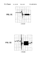
- FIGS. 3 a to 3 d illustrate exemplary strip chart records of output of the sensor introduced in FIGS. 1 and 2 taken during illustrative situations;
- FIG. 4 illustrates an operational flow diagram of an exemplary method of programming a processor in accordance with a fall detection application of the principles of the present invention
- FIG. 5 illustrates a functional block diagram of an alternate sensing system that may suitably be associated with the processor of the present invention
- FIG. 6 illustrates a perspective view of an exemplary remote receiver unit of the system of this invention
- FIG. 7 illustrates a functional block diagram of the exemplary receiver unit of FIG. 6.
- FIG. 8 illustrates an exemplary wireless network that is associated via a wired network, such as the Internet, to a remote monitoring controller according to one embodiment of the present invention.
- FIG. 1 there is illustrated an isometric view of an exemplary embodiment of a system (generally designated 11 ) that evaluates body movement in accordance with the principles of the present invention, and more particularly that measures and distinguishes selected accelerative events of a body (not shown).
- the phrases “accelerative events” or “accelerative phenomena” are defined as occurrences of change in velocity of the body (or acceleration), whether in magnitude, direction or both.
- System 11 includes circuit boards 13 and 15 (connected boards at right angles to one another) that are associated with a housing (generally designated 17 ) utilizing known mounting techniques.
- Exemplary housing 17 (and system 11 , for that matter), when assembled, is approximately one centimeter thick and is approximately five centimeters across in any direction.
- Housing 17 may comprise, for example, exemplary housing halves 19 and 21 that encase boards 13 and 15 , although those skilled in the art will understand that any configuration suitable for a particular implementation of the invention may be arranged.
- Exemplary rear half 21 is provided with a clip 23 for associating system 11 with the body (e.g., people, animals, objects of various sorts, etc.).
- exemplary clip 23 is shown as a mechanical spring-type clip, but could be any known attachment device or system, including either mechanical or chemical attachment systems, or any other suitable means for associating system 11 with the body.
- System 11 includes a processor (shown in FIG. 2) and a sensor 25 .
- Exemplary sensor 25 operates to sense accelerative phenomena of the body, and is mounted on circuit board 13 with x and y axes 27 and 29 , respectively, oriented thereat (though other orientations could be utilized).
- Sensor 25 is illustratively shown as a plural-axis (dual shown) acceleration measuring device suitably mounted on a single monolithic integrated circuit (one conventional sensor is an accelerometer available from ANALOG DEVICES, INC., located at One Technology Way, Norwood, Mass., United States of America, namely, Model No. ADXL202).
- Sensor 25 includes polysilicon surface-micromachined sensor layer 31 built on top of silicon wafer 33 .
- Polysilicon springs 35 resiliently suspend sensor layer 31 over the surface of wafer 33 providing resistance against acceleration forces. Deflection of the sensor layer is measured using a differential capacitor formed by independent fixed and central plates, the fixed plates driven by 180° out of phase square waves having amplitude proportional to acceleration.
- Signal outputs from each axis of sensor 25 are conditioned (i.e., phase sensitive demodulation and low pass filtering) and presented at analog output nodes.
- the ANALOG DEVICES' accelerometer is operable to convert the analog signals to duty cycle modulated (“DCM”) signals at a DCM stage providing digital output signals capable of being directly counted at a processor.
- DCM duty cycle modulated
- While techniques for reconstructing analog signals from the digital output signals may suitably be utilized (e.g., passing the duty cycle signals though an RC filter), thereby allowing use of the digital signal output of a sensor of system 11 hereof.
- Use of the analog signal outputs has been found advantageous due to the increased bandwidth availability (0.01 Hz to 5 kHz, adjustable at capacitors at the output nodes to bandlimit the nodes implementing low-pass filtering for antialiasing and noise reduction), and thus measuring sensitivity, attained.
- a typical noise floor of 500 ⁇ g/Hz is achieved, thereby allowing signals below five miligrams (5 mg) to be resolved for bandwidths below 60 Hz.
- sensor 25 generates analog output voltage signals corresponding to measurements in the x and y axes, which include both an ac voltage component proportional to G forces (i.e., dynamic acceleration component related to vibrations of sensor layer 31 ) and a dc voltage component proportional to an angle relative to earth (i.e., static acceleration component related to gravity).
- This open loop acceleration measurement architecture capable of measuring both static and dynamic acceleration, can thus be utilized to determine position of a body by measuring both the x and y output voltages simultaneously, as well as measure forces of impact experienced by a body.
- This information comprises state indicia, and utilizing both signal components from both outputs, the sensed accelerative phenomena of the body may subsequently be processed to distinguish a variety of accelerative phenomena and, ultimately, to selectively act based on the distinctions, as is described in detail hereafter to determine whether the evaluated body movement is normal or abnormal, and, if abnormal, whether the same is within tolerance.
- any sensor that is capable of sensing accelerative phenomena relative to a body may be used in lieu of, or even in conjunction with, sensor 25 .
- alternate orientations of sensor 25 may be used for different applications.
- FIG. 2 there is illustrated a block diagram of the exemplary system of FIG. 1, which includes processing circuitry 39 , indicating means 41 , power supply 67 , and a switch 68 , along with sensor 25 .
- Exemplary processing circuitry 39 illustratively includes a processor 47 and buffer amplifiers 43 and 45 that buffer the analog x and y outputs from sensor 25 .
- Exemplary processor 47 which is associated with sensor 25 , is capable of processing the sensed accelerative phenomena as a function of at least one accelerative event characteristic to thereby determine whether an evaluated body movement is within environmental tolerance.
- Processor 47 also preferably generates state indicia while processing the sensed accelerative phenomena, which may represent the state of the body within the environment over time.
- Processor 47 is associated with a crystal oscillator/clock 49 , switch (DIP) inputs 51 , an analog-digital conversion circuitry 53 and a DSP filter 55 (one conventional processor is available from TEXAS INSTRUMENTS, INC. , located in Dallas, Tex., United States of America, namely, Model No. MSP430P325).
- Exemplary indicating means 41 in response to direction from processor 47 , is operable to at least one of initiate an alarm event; communicate such state, or tolerance, indicia to a monitoring controller; generate statistics; etc.
- Indicating means 41 may take any number of forms, however, for use in system 11 of the present embodiment, stage 41 is an RF transmitter including RF modulator 61 enabled by processor 47 . Exemplary data is presented and modulated at modulator 61 , amplified at amplifier 63 and transmitted at antenna 65 (to a remote receiver unit as discussed hereinafter).
- power for the various components of system 11 is provided by power supply 67 , which illustratively is a conventional 3.6 volt battery.
- Low power management may suitably be under the control of processor 47 utilizing exemplary switched/power supply voltage FET switch 68 at sensor 25 , which provides power only during sampling cycles, and operates to shut components down during non-use cycles. For instance, processor 47 may be taken off-line when processing is complete, reducing current drain.
- System 11 may be implemented using any suitably arranged computer or other processing system including micro, personal, mini, mainframe or super computers, as well as network combinations of two or more of the same.
- sensor 25 and processor 47 are not co-located, but rather associated wirelessly.
- the principles of the present invention may be implemented in any appropriately arranged device having processing circuitry.
- Processing circuitry may include one or more conventional processors, programmable logic devices, such as programmable array logic (“PALs”) and programmable logic arrays (“PLAs”), digital signal processors (“DSPs”), field programmable gate arrays (“FPGAs”), application specific integrated circuits (“ASICs”), large scale integrated circuits (“LSIs”), very large scale integrated circuits (“VLSIs”) or the like, to form the various types of circuitry, processors, controllers or systems described and claimed herein.
- PALs programmable array logic
- PLAs programmable logic arrays
- DSPs digital signal processors
- FPGAs field programmable gate arrays
- ASICs application specific integrated circuits
- LSIs large scale integrated circuits
- VLSIs very large scale integrated circuits
- FIGS. 3 a to 3 d illustrated are exemplary strip chart records of output of exemplary sensor 25 of FIGS. 1 and 2 taken during illustrative situations. More particularly, FIGS. 3 a and 3 b illustrate the analog signal at the x and y outputs of sensor 25 during a fall by a body to the left, and whereas FIGS. 3 c and 3 d illustrate the analog signal at the x and y outputs of sensor 25 during a fall by a body to the right (the dark blocks indicating an alarm condition).
- a fall to the left and to the right are both distinguishable by the disruption of a stable position, or normal body movement, by a concussive force followed by a distinctly different ending stable position.
- the direction of fall is clear from the position of the ending trace at the y outputs. If the fall had been more forward or backward, the x output traces would likewise clearly indicate the same (this assumes x and y sensor axes orientation as set forth in FIG. 1 ).
- the same x and y outputs of the sensor 25 may be suitably processed to simply determine position of the body, for instance, such as when a person is lying down, when a box has tipped over, etc.
- FIG. 4 illustrated is operational flow diagram of an exemplary method (generally designated 400 ) of programming of processor 47 in accordance with a fall detection application of the principles of the present invention.
- 400 an exemplary method of programming of processor 47 in accordance with a fall detection application of the principles of the present invention.
- system 11 of FIGS. 1 and 2 For the purposes of illustration, concurrent reference is made to system 11 of FIGS. 1 and 2. It should be noted that this illustration introduces an exemplary operational method for programming processor 47 for its use as a fall detector, and that suitable alternate embodiments of system 11 for evaluating movement of a body relative to different environments may likewise be implemented in accordance with the principles hereof, such as for relative position, other assistance monitoring, transparent monitoring, tactical maneuver monitoring etc.
- Exemplary method 400 begins and a request for sampling measurements is generated, likely by processor 47 (Step 405 ), either in response to an executing operations program or upon initiation by a user, possibly remotely from a monitoring controller (discussed with reference to FIG. 8 ).
- Sensor 25 sense x and y acceleration values generating measurement signals at the outputs at sensor 25 .
- the measurement signals are converted from analog to digital format and filtered by filter 55 (Step 410 ; thereby reducing probability that an out-of-tolerance abnormal movement will be determined incorrectly in response to a single sharp impact, such as a collision between mount 17 and a hard surface when sensor 25 is off the body causing a sharp signal spike).
- Processor 47 uses dc voltage components of the outputs from sensor 25 to determine a last stable position of the body on which sensor 25 is mounted (Step 415 ). More particularly, processor 47 repeatedly compares successive input values with immediately preceding input values and, if within tolerance, are added thereto and stored in an accumulator. This is repeated until Z samples have been accumulated and added over some defined period of time (e.g., one second) or until a received input is out of tolerance, in which case the sampling cycle is reinitiated. When Z samples are accumulated and added, the accumulated value is divided by Z to determine a “last stable” static acceleration average value, which is saved and is indicative of the last stable position of the body. Sampling and/or sampling cycle rates may be varied, but, while preferably not continuous due to power consumption concerns, should be substantially continual. It is important to note, therefore, that such characteristics maybe statically maintained or dynamically generated.
- Processor 47 uses ac voltage components of each output from sensor 25 to check against a G force threshold value set at DIP switch 51 to see if it exceeds the threshold (Step 420 ; thus qualifying as a potential fall impact, in the current example, possibly an intensity in excess of about 2 to 4 G depending upon desired sensitivity). According to the present implementation, if three of these dynamic acceleration measurements are received in excess of the threshold without five intervening measurements that are less than the threshold, the impact detect flag may be set.
- Processor 47 determines a fall by testing a post-impact stream of samples against a tolerance (Step 425 ; for instance, a selected value of the ac voltage components, for example a value less than about 2 G). Each new sample is tested against the previous sample to see if the position of the body has stabilized. When the position has stabilized to less than the tolerance, W samples are averaged to get the new stable static acceleration average value corresponding to the new stable position.
- a tolerance for instance, a selected value of the ac voltage components, for example a value less than about 2 G.
- Processor 47 in response to the value corresponding to the new stable position is shifted indicating a change of body position of 45° or more from the last stable position, classifies the event as a debilitating fall and alert stage 41 is activated (Step 430 ).
- a greater stabilization or post-stabilization sample period may be selected to allow more time for an uninjured user to rise without issuance of an alert.
- Processor 47 after setting the last stable position, adds the absolute values of the x and y last stable positions together, and, then determines whether the body associated with sensor 25 is lying down if the added value exceeds a value corresponding to 90° plus or minus 25% (Step 435 ). In such case, after a selected time (for example, four seconds) with repeated like values, the lying down detect flag is set. While this flag is set, any impact that exceeds the G force threshold is treated as a debilitating fall (Step 440 ). The flag is set only as long as the added value continues to indicate that the wearer is lying down.
- processor 47 is operable to process sensed accelerative phenomena as a function of at least one accelerative event characteristic, and that such characteristics will largely be defined by the specific application. Therefore, system 11 , and, more particularly, processor 47 , generates state indicia relative the environment of interest, and determines whether the evaluated body movement is within tolerance in the context of that environment. For instance, “tolerance” would likely be very different for a monitored body of an elderly person with a heart condition, a toddler, a box in a freight car, a container of combustible gas, etc.
- FIG. 5 illustrated is a functional block diagram of an alternate sensing system (generally designated 71 ) that may suitably be associated with processor 47 of FIGS. 1, 2 , and 4 in accordance with the principles of the present invention.
- components utilizable with system 11 are configured again as a human fall monitor/detector, and any or all of these additional monitoring functions may be employed with system 11 .
- concurrent reference is made to processor 47 of FIGS. 2 and 4.
- Exemplary sensor 71 includes a respiration module 73 , which includes a body contact breath sensor 75 (for example a volumetric sensor, or a near body breath sensor), low pass filter 77 and amplifier 79 providing output signals indicative of respiration rate and vitality to processor 47 .
- the outputs are processed and, when a dangerous respiratory condition is suggested (generates state indicia relative the environment, and determines whether the evaluated body movement (broadly defined herein to include organic physiologic phenomena) is within environmental tolerance), an identifiable (for example, by signal coding) alarm sent indicating means 41 .
- Sensor 71 further includes an ECG module 81 , which includes input electrodes 83 and 85 providing heart rate signals to filters 87 and 89 .
- the filtered signals are amplified at amplifier 91 and band pass filtered at filter 93 .
- the output is amplified at 95 for input to processor 47 and processed so that dangerous heart rhythms and events can be detected (generates state indicia relative the environment, and determines whether the evaluated body movement is within environmental tolerance) and an identifiable alarm sent at alert stage 41 .
- Sensor 71 further includes a panic button module 97 that is operable using a standard user activated switch 99 positioned at housing 17 allowing a user to initiate a call for help.
- the switch output is input to processor 47 to initiate an identifiable alarm at alert stage 41 .
- FIGS. 6 and 7 illustrated are a perspective view of an exemplary remote receiver unit of the system of this invention and a functional block diagram of the same.
- a remote receiver unit 103 for example a wall mountable unit as shown in FIGS. 6 and 7 is provided for receipt of transmissions from sensor 25 and/or system 71 .
- Unit 103 includes a receiver antenna 105 , indicator LED's 107 (including indicators for as many detector functions as are employed in the specific embodiment of the apparatus being monitored, as well as an indicator for unit on/off status), and a user interface input keypad 111 for unit setup, reset and alarm deactivation.
- Power access 113 is provided at the bottom of the unit.
- RF receiver 115 is tuned to receive alarm transmissions from sensor 11 / 71 and presents the signal received for processing at processor 117 for alarm identification and appropriate output.
- Processor 117 also receives inputs from keypad 111 and power switch 119 .
- Non-volatile memory 121 is provided for input of identification of the user and/or of the apparatus being monitored.
- Audible alarm 123 , LED bank 107 and retransmission unit 125 are connected to receive outputs from processor 117 .
- an audible alarm is sounded and the appropriate LED (indicative of the condition causing the alarm, for example a debilitating fall by a user of apparatus 11 ) is activated. If not disabled by the user at key pad 111 within a short period, processor 117 activates retransmission unit 125 initiating a call for help or other remote notification.
- Operational setup of unit 103 is also accomplished under programming at processor 117 and by sequential operation by a user or technician of keypad 111 and/or power switch 119 as is known (including user ID set, learn mode operations, reset or reprogramming operations, and urgency code operations).
- FIG. 8 illustrated is an exemplary hybrid wireless/wired network (generally designated 800 ) that is associated with a remote monitoring controller 805 according to one embodiment of the present invention.
- the wireless network 810 is introduced for illustrative purposes only, and comprises a plurality of cell sites 821 to 823 , each containing one of the base stations, BS 801 , BS 802 , or BS 803 .
- Base stations 801 to 803 are operable to communicate with a plurality of mobile stations (MS) 103 (remote receiver unit 103 ), and 811 to 814 .
- MS mobile stations
- Mobile stations 103 , and 811 to 814 may be any suitable cellular devices, including conventional cellular telephones, PCS handset devices, portable computers, metering devices, transceivers, and the like (including, for instance, remote receiver unit 103 ).
- Dotted lines show the approximate boundaries of the cell sites 821 to 823 in which base stations 801 to 803 are located.
- the cell sites are shown approximately circular for the purposes of illustration and explanation only. It should be clearly understood that the cell sites also may have irregular shapes, depending on the cell configuration selected and natural and man-made obstructions.
- BS 801 , BS 802 , and BS 803 may comprise a base station controller (BSC) and a base transceiver station (BTS).
- BSC base station controller
- BTS base transceiver station
- a base station controller is a device that manages wireless communications resources, including the base transceiver station, for specified cells within a wireless communications network.
- a base transceiver station comprises the RF transceivers, antennas, and other electrical equipment located in each cell site. This equipment may include air conditioning units, heating units, electrical supplies, telephone line interfaces, and RF transmitters and RF receivers, as well as call processing circuitry.
- the base transceiver station in each of cells 821 , 822 , and 823 and the base station controller associated with each base transceiver station are collectively represented by BS 801 , BS 802 and BS 803 , respectively.
- BS 801 , BS 802 and BS 803 transfer voice and data signals between each other and the public telephone system (not shown) via communications line 831 and mobile switching center (MSC) 840 .
- Mobile switching center 840 is well known to those skilled in the art. Mobile switching center 840 is a switching device that provides services and coordination between the subscribers in a wireless network and external networks 850 , such as the Internet, public telephone system, etc.
- Communications line 831 may be any suitable connection means, including a T1 line, a T3 line, a fiber optic link, a network backbone connection, and the like.
- communications line 831 may be several different data links, where each data link couples one of BS 801 , BS 802 , or BS 803 to MSC 840 .
- MS 811 is located in cell site 821 and is in communication with BS 801
- MS 103 is located in cell site 822 and is in communication with BS 802
- MS 814 is located in cell site 823 and is in communication with BS 803
- MS 812 is also located in cell site 821 , close to the edge of cell site 823 .
- the direction arrow proximate MS 812 indicates the movement of MS 812 towards cell site 823 .
- system 11 is associated with an elderly person whose residence is wirelessly monitored. It is further assumed that sensor 25 is associated with the elderly person and that processor 47 is coupled in MS/remote receiver unit 103 , such that sensor 25 and processor 47 are wirelessly associated.
- System 11 repeatedly senses various physiological phenomena of the elderly person, including accelerative phenomena of his body.
- Remote processor 47 processes the repeatedly sensed phenomena, and, particularly, the accelerative phenomena of the body, as a function of at least one accelerative event characteristic to thereby determine whether the evaluated body movement is within environmental tolerance.
- Processor 47 advantageously generates state indicia while processing the sensed accelerative phenomena, representing the state of the body within the environment over time.
- Exemplary processor 47 is programmed to distinguish between normal and abnormal accelerative events (e.g., walking, sitting, lying down, etc. versus tripping, falling down, etc.), and, when an abnormal event is identified, indicates whether the abnormal event is tolerable, or within tolerance. Processor 47 may also suitably be programmed to distinguish other physical characteristics, including temperature, pressure, force, sound, light, relative position (including lying down), and the like.
- normal and abnormal accelerative events e.g., walking, sitting, lying down, etc. versus tripping, falling down, etc.
- Processor 47 may also suitably be programmed to distinguish other physical characteristics, including temperature, pressure, force, sound, light, relative position (including lying down), and the like.
- processor 47 uses the same to determine whether the evaluated body movement is within environmental tolerance. Preferably, such tolerance indicia is compared with at least one threshold, likely associated with the accelerative event characteristic. In response to such comparison, processor 47 controls a suitable indicating means to initiate an alarm event (locally and via network 810 to monitoring controller 805 ), to communicate such tolerance indicia to a monitoring controller 805 , to generate statistics (locally and via network 810 to monitoring controller 805 ), or the like.
- such state indicia, and other information is communicated from time to time to monitoring controller 805 , from which such information may suitably be perceived.
- a technician, medical professional, or relative might wish to review the activities and status of the elderly person. This may easily be facilitated via a centralized data repository accessible via the Internet 850 , or via any other suitably arranged Network 850 .
- the technician, medical professional, or relative (subscriber 2 , generally designated 855 ) might initiate a diagnostic equipment check, a physiological test, a simple status check, or the like.
- monitoring controller 805 via the network 800 , may monitor a “heartbeat” signal generated periodically by MS/remote receiver unit 103 , the heartbeat indicating that unit 103 is functional.
Abstract
Description
Claims (32)
Priority Applications (20)
| Application Number | Priority Date | Filing Date | Title |
|---|---|---|---|
| US09/396,991 US6307481B1 (en) | 1999-09-15 | 1999-09-15 | Systems for evaluating movement of a body and methods of operating the same |
| US09/476,591 US6147618A (en) | 1999-09-15 | 1999-12-31 | Apparatus and method for reducing power consumption in physiological condition monitors |
| US09/536,093 US6415033B1 (en) | 1999-09-15 | 2000-03-24 | Physiological condition monitors utilizing very low frequency acoustic signals |
| BR0014039-2A BR0014039A (en) | 1999-09-15 | 2000-09-15 | Systems for evaluating the movement of a body and methods of operating it |
| CA002385062A CA2385062A1 (en) | 1999-09-15 | 2000-09-15 | Systems for evaluating movement of a body and methods of operating the same |
| MXPA02002805A MXPA02002805A (en) | 1999-09-15 | 2000-09-15 | Systems for evaluating movement of a body and methods of operating the same. |
| AU75867/00A AU7586700A (en) | 1999-09-15 | 2000-09-15 | Systems for evaluating movement of a body and methods of operating the same |
| PCT/US2000/025477 WO2001020571A1 (en) | 1999-09-15 | 2000-09-15 | Systems for evaluating movement of a body and methods of operating the same |
| JP2001524075A JP2003509781A (en) | 1999-09-15 | 2000-09-15 | System for evaluating body movement and method of operating the same |
| TW089118947A TW494368B (en) | 1999-09-15 | 2000-09-15 | Systems for evaluating movement of a body and methods of operating the same |
| EP00965089A EP1212736A4 (en) | 1999-09-15 | 2000-09-15 | Systems for evaluating movement of a body and methods of operating the same |
| US09/711,607 US6377185B1 (en) | 1999-09-15 | 2000-11-13 | Apparatus and method for reducing power consumption in physiological condition monitors |
| US09/727,974 US6501386B2 (en) | 1999-09-15 | 2000-11-30 | Systems within a communication device for evaluating movement of a body and methods of operating the same |
| US09/804,723 US6661347B2 (en) | 1999-09-15 | 2001-03-13 | Systems within a position locator device for evaluating movement of a body and methods of operating the same |
| US09/909,404 US6703939B2 (en) | 1999-09-15 | 2001-07-19 | System and method for detecting motion of a body |
| US10/131,795 US6734802B2 (en) | 1999-09-15 | 2002-04-22 | Apparatus and method for reducing power consumption in physiological condition monitors |
| US10/187,456 US6947565B2 (en) | 1999-09-15 | 2002-07-01 | Physiological condition monitors utilizing very low frequency acoustic signals |
| US10/331,958 US6864796B2 (en) | 1999-09-15 | 2002-12-30 | Systems within a communication device for evaluating movement of a body and methods of operating the same |
| US10/796,595 US7095331B2 (en) | 1999-09-15 | 2004-03-09 | System and method for detecting motion of a body |
| US11/633,672 US7479890B2 (en) | 1999-09-15 | 2006-12-04 | System and method for analyzing activity of a body |
Applications Claiming Priority (1)
| Application Number | Priority Date | Filing Date | Title |
|---|---|---|---|
| US09/396,991 US6307481B1 (en) | 1999-09-15 | 1999-09-15 | Systems for evaluating movement of a body and methods of operating the same |
Related Child Applications (5)
| Application Number | Title | Priority Date | Filing Date |
|---|---|---|---|
| US09/476,591 Continuation-In-Part US6147618A (en) | 1999-09-15 | 1999-12-31 | Apparatus and method for reducing power consumption in physiological condition monitors |
| US09/536,093 Continuation-In-Part US6415033B1 (en) | 1999-09-15 | 2000-03-24 | Physiological condition monitors utilizing very low frequency acoustic signals |
| US09/727,974 Continuation-In-Part US6501386B2 (en) | 1999-09-15 | 2000-11-30 | Systems within a communication device for evaluating movement of a body and methods of operating the same |
| US09/804,723 Continuation-In-Part US6661347B2 (en) | 1999-09-15 | 2001-03-13 | Systems within a position locator device for evaluating movement of a body and methods of operating the same |
| US09/909,404 Continuation-In-Part US6703939B2 (en) | 1999-09-15 | 2001-07-19 | System and method for detecting motion of a body |
Publications (1)
| Publication Number | Publication Date |
|---|---|
| US6307481B1 true US6307481B1 (en) | 2001-10-23 |
Family
ID=23569449
Family Applications (1)
| Application Number | Title | Priority Date | Filing Date |
|---|---|---|---|
| US09/396,991 Expired - Lifetime US6307481B1 (en) | 1999-09-15 | 1999-09-15 | Systems for evaluating movement of a body and methods of operating the same |
Country Status (9)
| Country | Link |
|---|---|
| US (1) | US6307481B1 (en) |
| EP (1) | EP1212736A4 (en) |
| JP (1) | JP2003509781A (en) |
| AU (1) | AU7586700A (en) |
| BR (1) | BR0014039A (en) |
| CA (1) | CA2385062A1 (en) |
| MX (1) | MXPA02002805A (en) |
| TW (1) | TW494368B (en) |
| WO (1) | WO2001020571A1 (en) |
Cited By (44)
| Publication number | Priority date | Publication date | Assignee | Title |
|---|---|---|---|---|
| WO2001072228A1 (en) | 2000-03-24 | 2001-10-04 | Ilife Systems, Inc. | Physiological condition monitors utilizing very low frequency acoustic signals |
| US6611783B2 (en) * | 2000-01-07 | 2003-08-26 | Nocwatch, Inc. | Attitude indicator and activity monitoring device |
| US6661347B2 (en) * | 1999-09-15 | 2003-12-09 | Ilife Solutions, Inc. | Systems within a position locator device for evaluating movement of a body and methods of operating the same |
| US20040010390A1 (en) * | 2000-01-07 | 2004-01-15 | Kelly Paul B. | Attitude indicator and activity monitoring device |
| US6819247B2 (en) * | 2001-02-16 | 2004-11-16 | Locast Corporation | Apparatus, method, and system for remote monitoring of need for assistance based on change in velocity |
| US20040243148A1 (en) * | 2003-04-08 | 2004-12-02 | Wasielewski Ray C. | Use of micro- and miniature position sensing devices for use in TKA and THA |
| US20050067816A1 (en) * | 2002-12-18 | 2005-03-31 | Buckman Robert F. | Method and apparatus for body impact protection |
| US20050093709A1 (en) * | 2003-07-31 | 2005-05-05 | Wellcare Systems Inc. | Comprehensive monitoring system |
| US20050240086A1 (en) * | 2004-03-12 | 2005-10-27 | Metin Akay | Intelligent wearable monitor systems and methods |
| US6997882B1 (en) * | 2001-12-21 | 2006-02-14 | Barron Associates, Inc. | 6-DOF subject-monitoring device and method |
| US20060139166A1 (en) * | 2004-12-09 | 2006-06-29 | Christian Choutier | System and method for monitoring of activity and fall |
| US20060202816A1 (en) * | 2005-03-11 | 2006-09-14 | Cindy Crump | Mobile wireless customizable health and condition monitor |
| US20060270949A1 (en) * | 2003-08-15 | 2006-11-30 | Mathie Merryn J | Monitoring apparatus for ambulatory subject and a method for monitoring the same |
| US7149579B1 (en) | 2002-12-23 | 2006-12-12 | Pacesetter, Inc. | System and method for determining patient posture based on 3-D trajectory using an implantable medical device |
| US7149584B1 (en) | 2002-12-23 | 2006-12-12 | Pacesetter, Inc. | System and method for determining patient posture based on 3-D trajectory using an implantable medical device |
| US20070015611A1 (en) * | 2005-07-13 | 2007-01-18 | Ultimate Balance, Inc. | Orientation and motion sensing in athletic training systems, physical rehabilitation and evaluation systems, and hand-held devices |
| US20070027631A1 (en) * | 2005-07-29 | 2007-02-01 | Cabrera Michael Normann B | Apparatus and method for evaluating a hypertonic condition |
| US20080129518A1 (en) * | 2006-12-05 | 2008-06-05 | John Carlton-Foss | Method and system for fall detection |
| US20080140137A1 (en) * | 2006-12-11 | 2008-06-12 | Massachusetts Eye & Ear Infirmary | Control and Integration of Sensory Data |
| US20080288200A1 (en) * | 2007-05-18 | 2008-11-20 | Noble Christopher R | Newtonian physical activity monitor |
| US7562121B2 (en) | 2004-08-04 | 2009-07-14 | Kimberco, Inc. | Computer-automated system and method of assessing the orientation, awareness and responses of a person with reduced capacity |
| US20090299228A1 (en) * | 2008-06-02 | 2009-12-03 | Zimmer, Inc. | Implant sensors |
| US20100016745A1 (en) * | 2005-03-11 | 2010-01-21 | Aframe Digital, Inc. | Mobile wireless customizable health and condition monitor |
| US20100261980A1 (en) * | 2007-09-19 | 2010-10-14 | Koninklijke Philips Electronics N.V. | Method and apparatus for detecting an abnormal situation |
| US20110025493A1 (en) * | 2005-03-11 | 2011-02-03 | Aframe Digital, Inc. | Mobile wireless customizable health and condition monitor |
| US20110162433A1 (en) * | 2008-09-12 | 2011-07-07 | Koninklijke Philips Electronics N.V. | Fall detection system |
| US8660517B2 (en) | 2011-10-07 | 2014-02-25 | Jason Paul DeMont | Personal assistance monitoring system |
| US20140163425A1 (en) * | 2005-10-16 | 2014-06-12 | Bao Tran | Personal emergency response (per) system |
| US8938299B2 (en) | 2008-11-19 | 2015-01-20 | Inspire Medical Systems, Inc. | System for treating sleep disordered breathing |
| US8956418B2 (en) | 2005-02-18 | 2015-02-17 | Zimmer, Inc. | Smart joint implant sensors |
| US9028407B1 (en) | 2013-12-13 | 2015-05-12 | Safer Care LLC | Methods and apparatus for monitoring patient conditions |
| US9107615B2 (en) | 2002-12-18 | 2015-08-18 | Active Protective Technologies, Inc. | Method and apparatus for body impact protection |
| US9138172B2 (en) | 2011-02-24 | 2015-09-22 | Rochester Institute Of Technology | Method for monitoring exposure to an event and device thereof |
| US9339224B2 (en) | 2011-02-24 | 2016-05-17 | Rochester Institute Of Technology | Event dosimeter devices and methods thereof |
| US9345433B1 (en) | 2014-12-09 | 2016-05-24 | SensaRx, LLC | Affixation of objects to garments |
| US9588582B2 (en) | 2013-09-17 | 2017-03-07 | Medibotics Llc | Motion recognition clothing (TM) with two different sets of tubes spanning a body joint |
| US9603573B2 (en) | 2014-04-14 | 2017-03-28 | Brain Sentinel, Inc. | Detection of EMG activity using sensors on both sides of the body |
| US9734690B2 (en) | 2015-04-15 | 2017-08-15 | Nortek Security & Controls LLC | System and method for activity monitoring and fall detection |
| RU2670386C2 (en) * | 2015-08-13 | 2018-10-22 | Сяоми Инк. | Method and device for controlling alarm system, electronic device |
| US10244986B2 (en) | 2013-01-23 | 2019-04-02 | Avery Dennison Corporation | Wireless sensor patches and methods of manufacturing |
| US10292445B2 (en) | 2011-02-24 | 2019-05-21 | Rochester Institute Of Technology | Event monitoring dosimetry apparatuses and methods thereof |
| US10349902B2 (en) | 2014-09-12 | 2019-07-16 | Brain Sentinel, Inc. | Method and apparatus for communication between a sensor and a managing device |
| US10583297B2 (en) | 2011-08-11 | 2020-03-10 | Inspire Medical Systems, Inc. | Method and system for applying stimulation in treating sleep disordered breathing |
| US10898709B2 (en) | 2015-03-19 | 2021-01-26 | Inspire Medical Systems, Inc. | Stimulation for treating sleep disordered breathing |
Families Citing this family (1)
| Publication number | Priority date | Publication date | Assignee | Title |
|---|---|---|---|---|
| US7554578B2 (en) | 2000-07-11 | 2009-06-30 | Phase One A/S | Digital camera with integrated accelerometers |
Citations (18)
| Publication number | Priority date | Publication date | Assignee | Title |
|---|---|---|---|---|
| US3614763A (en) | 1969-03-18 | 1971-10-19 | Anthony Yannuzzi | Prone position alarm |
| US4110741A (en) | 1976-01-20 | 1978-08-29 | Societe Chimique Des Charbonnages | Device for monitoring physical activity of persons |
| US4284986A (en) | 1980-06-23 | 1981-08-18 | Carlos Amortegui | Shirt-pocket medical alert device |
| US4292630A (en) | 1978-09-19 | 1981-09-29 | Societe d'Etudes Techniques et Commerciales d'Automation | Device for the obtaining of an electric signal which is proportional to an amount of movement and therefore capable of detecting any movement or acceleration |
| US4829285A (en) | 1987-06-11 | 1989-05-09 | Marc I. Brand | In-home emergency assist device |
| US4858622A (en) | 1987-04-01 | 1989-08-22 | J.D. Monitoring, Incorporated | Fall alert system with magnetically operable switch |
| US5045839A (en) * | 1990-03-08 | 1991-09-03 | Rand G. Ellis | Personnel monitoring man-down alarm and location system |
| US5146206A (en) | 1989-11-07 | 1992-09-08 | Callaway James J | Patient ambulation motion detector with multiple switch motion detection |
| US5300921A (en) | 1992-11-13 | 1994-04-05 | Rhys Resources Ins. | Athletic training system |
| US5402107A (en) * | 1993-01-29 | 1995-03-28 | Allied Services Foundation, Inc. | Apparatus for sensing body attitude |
| US5430435A (en) * | 1992-11-13 | 1995-07-04 | Rhys Resources | Adjustable athletic training system |
| US5477211A (en) | 1994-10-19 | 1995-12-19 | Reynolds; Jeffrey J. | Ambulatory aid warning device |
| US5523742A (en) | 1993-11-18 | 1996-06-04 | The United States Of America As Represented By The Secretary Of The Army | Motion sensor |
| US5554975A (en) | 1992-10-06 | 1996-09-10 | Hall; H. Eugene | Safety device for the proprioception impaired |
| US5694340A (en) * | 1995-04-05 | 1997-12-02 | Kim; Charles Hongchul | Method of training physical skills using a digital motion analyzer and an accelerometer |
| US5751214A (en) | 1995-12-13 | 1998-05-12 | Alertcare, Inc. | Patient activity monitoring device with multiple sensors |
| US5941836A (en) * | 1996-06-12 | 1999-08-24 | Friedman; Mark B. | Patient position monitor |
| US5957957A (en) * | 1995-03-30 | 1999-09-28 | Medtronic, Inc. | Rate responsive cardiac pacemaker with tilt sensor |
Family Cites Families (2)
| Publication number | Priority date | Publication date | Assignee | Title |
|---|---|---|---|---|
| US4418337A (en) * | 1981-08-03 | 1983-11-29 | Spectrol Electronics Corporation | Alarm device |
| FR2763156B1 (en) * | 1997-05-06 | 1999-07-23 | Suisse Electronique Microtech | DEVICE FOR MONITORING THE ACTIVITY OF A PERSON AND / OR FOR DETECTING A FALL, IN PARTICULAR WITH A VIEW TO PROVIDING HIM / HER WITH RESCUE IN THE EVENT OF AN INCIDENT ENDANGING HIS SURVIVAL OR ITS GENERAL CONDITION |
-
1999
- 1999-09-15 US US09/396,991 patent/US6307481B1/en not_active Expired - Lifetime
-
2000
- 2000-09-15 MX MXPA02002805A patent/MXPA02002805A/en not_active Application Discontinuation
- 2000-09-15 CA CA002385062A patent/CA2385062A1/en not_active Abandoned
- 2000-09-15 JP JP2001524075A patent/JP2003509781A/en active Pending
- 2000-09-15 AU AU75867/00A patent/AU7586700A/en not_active Abandoned
- 2000-09-15 BR BR0014039-2A patent/BR0014039A/en not_active Application Discontinuation
- 2000-09-15 EP EP00965089A patent/EP1212736A4/en not_active Withdrawn
- 2000-09-15 WO PCT/US2000/025477 patent/WO2001020571A1/en active Search and Examination
- 2000-09-15 TW TW089118947A patent/TW494368B/en not_active IP Right Cessation
Patent Citations (19)
| Publication number | Priority date | Publication date | Assignee | Title |
|---|---|---|---|---|
| US3614763A (en) | 1969-03-18 | 1971-10-19 | Anthony Yannuzzi | Prone position alarm |
| US4110741A (en) | 1976-01-20 | 1978-08-29 | Societe Chimique Des Charbonnages | Device for monitoring physical activity of persons |
| US4292630A (en) | 1978-09-19 | 1981-09-29 | Societe d'Etudes Techniques et Commerciales d'Automation | Device for the obtaining of an electric signal which is proportional to an amount of movement and therefore capable of detecting any movement or acceleration |
| US4284986A (en) | 1980-06-23 | 1981-08-18 | Carlos Amortegui | Shirt-pocket medical alert device |
| US4858622A (en) | 1987-04-01 | 1989-08-22 | J.D. Monitoring, Incorporated | Fall alert system with magnetically operable switch |
| US4829285A (en) | 1987-06-11 | 1989-05-09 | Marc I. Brand | In-home emergency assist device |
| US5146206A (en) | 1989-11-07 | 1992-09-08 | Callaway James J | Patient ambulation motion detector with multiple switch motion detection |
| US5045839A (en) * | 1990-03-08 | 1991-09-03 | Rand G. Ellis | Personnel monitoring man-down alarm and location system |
| US5554975A (en) | 1992-10-06 | 1996-09-10 | Hall; H. Eugene | Safety device for the proprioception impaired |
| US5300921A (en) | 1992-11-13 | 1994-04-05 | Rhys Resources Ins. | Athletic training system |
| US5430435A (en) * | 1992-11-13 | 1995-07-04 | Rhys Resources | Adjustable athletic training system |
| US5402107A (en) * | 1993-01-29 | 1995-03-28 | Allied Services Foundation, Inc. | Apparatus for sensing body attitude |
| US5523742A (en) | 1993-11-18 | 1996-06-04 | The United States Of America As Represented By The Secretary Of The Army | Motion sensor |
| US5879309A (en) * | 1993-11-18 | 1999-03-09 | Johnson; Mark A. | Personal motion event monitor |
| US5477211A (en) | 1994-10-19 | 1995-12-19 | Reynolds; Jeffrey J. | Ambulatory aid warning device |
| US5957957A (en) * | 1995-03-30 | 1999-09-28 | Medtronic, Inc. | Rate responsive cardiac pacemaker with tilt sensor |
| US5694340A (en) * | 1995-04-05 | 1997-12-02 | Kim; Charles Hongchul | Method of training physical skills using a digital motion analyzer and an accelerometer |
| US5751214A (en) | 1995-12-13 | 1998-05-12 | Alertcare, Inc. | Patient activity monitoring device with multiple sensors |
| US5941836A (en) * | 1996-06-12 | 1999-08-24 | Friedman; Mark B. | Patient position monitor |
Cited By (84)
| Publication number | Priority date | Publication date | Assignee | Title |
|---|---|---|---|---|
| US6947565B2 (en) * | 1999-09-15 | 2005-09-20 | Ilife Solutions, Inc. | Physiological condition monitors utilizing very low frequency acoustic signals |
| US20030072458A1 (en) * | 1999-09-15 | 2003-04-17 | Ilife Solutions, Inc. | Physiological condition monitors utilizing very low frequency acoustic signals |
| US6661347B2 (en) * | 1999-09-15 | 2003-12-09 | Ilife Solutions, Inc. | Systems within a position locator device for evaluating movement of a body and methods of operating the same |
| US6611783B2 (en) * | 2000-01-07 | 2003-08-26 | Nocwatch, Inc. | Attitude indicator and activity monitoring device |
| US20040010390A1 (en) * | 2000-01-07 | 2004-01-15 | Kelly Paul B. | Attitude indicator and activity monitoring device |
| US7127370B2 (en) * | 2000-01-07 | 2006-10-24 | Nocwatch International Inc. | Attitude indicator and activity monitoring device |
| WO2001072228A1 (en) | 2000-03-24 | 2001-10-04 | Ilife Systems, Inc. | Physiological condition monitors utilizing very low frequency acoustic signals |
| US6819247B2 (en) * | 2001-02-16 | 2004-11-16 | Locast Corporation | Apparatus, method, and system for remote monitoring of need for assistance based on change in velocity |
| US6997882B1 (en) * | 2001-12-21 | 2006-02-14 | Barron Associates, Inc. | 6-DOF subject-monitoring device and method |
| US7150048B2 (en) * | 2002-12-18 | 2006-12-19 | Buckman Robert F | Method and apparatus for body impact protection |
| US10149638B2 (en) | 2002-12-18 | 2018-12-11 | Active Protective Technologies, Inc. | Method and apparatus for body impact protection |
| US20050067816A1 (en) * | 2002-12-18 | 2005-03-31 | Buckman Robert F. | Method and apparatus for body impact protection |
| US9107615B2 (en) | 2002-12-18 | 2015-08-18 | Active Protective Technologies, Inc. | Method and apparatus for body impact protection |
| US7149579B1 (en) | 2002-12-23 | 2006-12-12 | Pacesetter, Inc. | System and method for determining patient posture based on 3-D trajectory using an implantable medical device |
| US7149584B1 (en) | 2002-12-23 | 2006-12-12 | Pacesetter, Inc. | System and method for determining patient posture based on 3-D trajectory using an implantable medical device |
| US20040243148A1 (en) * | 2003-04-08 | 2004-12-02 | Wasielewski Ray C. | Use of micro- and miniature position sensing devices for use in TKA and THA |
| US8241296B2 (en) | 2003-04-08 | 2012-08-14 | Zimmer, Inc. | Use of micro and miniature position sensing devices for use in TKA and THA |
| US20090138019A1 (en) * | 2003-04-08 | 2009-05-28 | Zimmer, Inc. | Use of micro and miniature position sensing devices for use in tka and tha |
| US7394385B2 (en) | 2003-07-31 | 2008-07-01 | Wellcare Systems, Inc. | Comprehensive monitoring system |
| US20050093709A1 (en) * | 2003-07-31 | 2005-05-05 | Wellcare Systems Inc. | Comprehensive monitoring system |
| US20060270949A1 (en) * | 2003-08-15 | 2006-11-30 | Mathie Merryn J | Monitoring apparatus for ambulatory subject and a method for monitoring the same |
| US20050240086A1 (en) * | 2004-03-12 | 2005-10-27 | Metin Akay | Intelligent wearable monitor systems and methods |
| US7981058B2 (en) * | 2004-03-12 | 2011-07-19 | The Trustees Of Dartmouth College | Intelligent wearable monitor systems and methods |
| US7562121B2 (en) | 2004-08-04 | 2009-07-14 | Kimberco, Inc. | Computer-automated system and method of assessing the orientation, awareness and responses of a person with reduced capacity |
| US8635282B2 (en) | 2004-08-04 | 2014-01-21 | Kimberco, Inc. | Computer—automated system and method of assessing the orientation, awareness and responses of a person with reduced capacity |
| US7966378B2 (en) | 2004-08-04 | 2011-06-21 | Kimberco, Inc. | Computer-automated system and method of assessing the orientation, awareness and responses of a person with reduced capacity |
| US20060139166A1 (en) * | 2004-12-09 | 2006-06-29 | Christian Choutier | System and method for monitoring of activity and fall |
| US9615777B2 (en) | 2004-12-09 | 2017-04-11 | Christian Cloutier | System and method for monitoring of activity and fall |
| US10299704B2 (en) | 2004-12-09 | 2019-05-28 | Groupe Everclose Inc. | Method for monitoring of activity and fall |
| US10531826B2 (en) | 2005-02-18 | 2020-01-14 | Zimmer, Inc. | Smart joint implant sensors |
| US8956418B2 (en) | 2005-02-18 | 2015-02-17 | Zimmer, Inc. | Smart joint implant sensors |
| US7616110B2 (en) | 2005-03-11 | 2009-11-10 | Aframe Digital, Inc. | Mobile wireless customizable health and condition monitor |
| US8378811B2 (en) | 2005-03-11 | 2013-02-19 | Aframe Digital, Inc. | Mobile wireless customizable health and condition monitor |
| US20100016745A1 (en) * | 2005-03-11 | 2010-01-21 | Aframe Digital, Inc. | Mobile wireless customizable health and condition monitor |
| US8618930B2 (en) * | 2005-03-11 | 2013-12-31 | Aframe Digital, Inc. | Mobile wireless customizable health and condition monitor |
| US20110025493A1 (en) * | 2005-03-11 | 2011-02-03 | Aframe Digital, Inc. | Mobile wireless customizable health and condition monitor |
| US20060202816A1 (en) * | 2005-03-11 | 2006-09-14 | Cindy Crump | Mobile wireless customizable health and condition monitor |
| US20070015611A1 (en) * | 2005-07-13 | 2007-01-18 | Ultimate Balance, Inc. | Orientation and motion sensing in athletic training systems, physical rehabilitation and evaluation systems, and hand-held devices |
| US7383728B2 (en) | 2005-07-13 | 2008-06-10 | Ultimate Balance, Inc. | Orientation and motion sensing in athletic training systems, physical rehabilitation and evaluation systems, and hand-held devices |
| US7478009B2 (en) | 2005-07-29 | 2009-01-13 | Wake Forest University Health Sciences | Apparatus and method for evaluating a hypertonic condition |
| US20090118649A1 (en) * | 2005-07-29 | 2009-05-07 | Cabrera Michael Normann B | Apparatus and Method for Evaluating a Hypertonic Condition |
| US20070027631A1 (en) * | 2005-07-29 | 2007-02-01 | Cabrera Michael Normann B | Apparatus and method for evaluating a hypertonic condition |
| US20140163425A1 (en) * | 2005-10-16 | 2014-06-12 | Bao Tran | Personal emergency response (per) system |
| US9901252B2 (en) | 2006-06-30 | 2018-02-27 | Koninklijke Philips N.V. | Mesh network personal emergency response appliance |
| US10307060B2 (en) | 2006-06-30 | 2019-06-04 | Koninklijke Philips N.V. | Mesh network personal emergency response appliance |
| US9775520B2 (en) | 2006-06-30 | 2017-10-03 | Empire Ip Llc | Wearable personal monitoring system |
| US10517479B2 (en) | 2006-06-30 | 2019-12-31 | Koninklijke Philips N.V. | Mesh network personal emergency response appliance |
| US9351640B2 (en) | 2006-06-30 | 2016-05-31 | Koninklijke Philips N.V. | Personal emergency response (PER) system |
| US11696682B2 (en) | 2006-06-30 | 2023-07-11 | Koninklijke Philips N.V. | Mesh network personal emergency response appliance |
| US9204796B2 (en) | 2006-06-30 | 2015-12-08 | Empire Ip Llc | Personal emergency response (PER) system |
| US8217795B2 (en) | 2006-12-05 | 2012-07-10 | John Carlton-Foss | Method and system for fall detection |
| US20080129518A1 (en) * | 2006-12-05 | 2008-06-05 | John Carlton-Foss | Method and system for fall detection |
| US8235918B2 (en) * | 2006-12-11 | 2012-08-07 | Massachusetts Eye & Ear Infirmary | Control and integration of sensory data |
| US20080140137A1 (en) * | 2006-12-11 | 2008-06-12 | Massachusetts Eye & Ear Infirmary | Control and Integration of Sensory Data |
| US8529477B2 (en) * | 2006-12-11 | 2013-09-10 | Massachusetts Eye & Ear Infirmary | Control and integration of sensory data |
| US20130030330A1 (en) * | 2006-12-11 | 2013-01-31 | The Trustees Of Boston University | Control and Integration of Sensory Data |
| US20080288200A1 (en) * | 2007-05-18 | 2008-11-20 | Noble Christopher R | Newtonian physical activity monitor |
| US7634379B2 (en) | 2007-05-18 | 2009-12-15 | Ultimate Balance, Inc. | Newtonian physical activity monitor |
| US20100261980A1 (en) * | 2007-09-19 | 2010-10-14 | Koninklijke Philips Electronics N.V. | Method and apparatus for detecting an abnormal situation |
| US20090299228A1 (en) * | 2008-06-02 | 2009-12-03 | Zimmer, Inc. | Implant sensors |
| US8029566B2 (en) | 2008-06-02 | 2011-10-04 | Zimmer, Inc. | Implant sensors |
| US8381603B2 (en) * | 2008-09-12 | 2013-02-26 | Koninklijke Philips Electronics N.V. | Fall detection system |
| US20110162433A1 (en) * | 2008-09-12 | 2011-07-07 | Koninklijke Philips Electronics N.V. | Fall detection system |
| US10888267B2 (en) | 2008-11-19 | 2021-01-12 | Inspire Medical Systems, Inc. | Method of treating sleep disordered breathing |
| US8938299B2 (en) | 2008-11-19 | 2015-01-20 | Inspire Medical Systems, Inc. | System for treating sleep disordered breathing |
| US10292445B2 (en) | 2011-02-24 | 2019-05-21 | Rochester Institute Of Technology | Event monitoring dosimetry apparatuses and methods thereof |
| US9339224B2 (en) | 2011-02-24 | 2016-05-17 | Rochester Institute Of Technology | Event dosimeter devices and methods thereof |
| US9668689B2 (en) | 2011-02-24 | 2017-06-06 | Rochester Institute Of Technology | Event dosimeter device and methods thereof |
| US9138172B2 (en) | 2011-02-24 | 2015-09-22 | Rochester Institute Of Technology | Method for monitoring exposure to an event and device thereof |
| US11511117B2 (en) | 2011-08-11 | 2022-11-29 | Inspire Medical Systems, Inc. | Method and system for applying stimulation in treating sleep disordered breathing |
| US10583297B2 (en) | 2011-08-11 | 2020-03-10 | Inspire Medical Systems, Inc. | Method and system for applying stimulation in treating sleep disordered breathing |
| US8660517B2 (en) | 2011-10-07 | 2014-02-25 | Jason Paul DeMont | Personal assistance monitoring system |
| US10244986B2 (en) | 2013-01-23 | 2019-04-02 | Avery Dennison Corporation | Wireless sensor patches and methods of manufacturing |
| US9588582B2 (en) | 2013-09-17 | 2017-03-07 | Medibotics Llc | Motion recognition clothing (TM) with two different sets of tubes spanning a body joint |
| US9028407B1 (en) | 2013-12-13 | 2015-05-12 | Safer Care LLC | Methods and apparatus for monitoring patient conditions |
| US9603573B2 (en) | 2014-04-14 | 2017-03-28 | Brain Sentinel, Inc. | Detection of EMG activity using sensors on both sides of the body |
| US10349902B2 (en) | 2014-09-12 | 2019-07-16 | Brain Sentinel, Inc. | Method and apparatus for communication between a sensor and a managing device |
| US9468399B2 (en) | 2014-12-09 | 2016-10-18 | SensaRx, LLC | Detection of changes from a seated or lying body position by sensing body angle |
| US9345433B1 (en) | 2014-12-09 | 2016-05-24 | SensaRx, LLC | Affixation of objects to garments |
| US10898709B2 (en) | 2015-03-19 | 2021-01-26 | Inspire Medical Systems, Inc. | Stimulation for treating sleep disordered breathing |
| US11806526B2 (en) | 2015-03-19 | 2023-11-07 | Inspire Medical Systems, Inc. | Stimulation for treating sleep disordered breathing |
| US11850424B2 (en) | 2015-03-19 | 2023-12-26 | Inspire Medical Systems, Inc. | Stimulation for treating sleep disordered breathing |
| US9734690B2 (en) | 2015-04-15 | 2017-08-15 | Nortek Security & Controls LLC | System and method for activity monitoring and fall detection |
| RU2670386C2 (en) * | 2015-08-13 | 2018-10-22 | Сяоми Инк. | Method and device for controlling alarm system, electronic device |
Also Published As
| Publication number | Publication date |
|---|---|
| AU7586700A (en) | 2001-04-17 |
| BR0014039A (en) | 2002-07-30 |
| MXPA02002805A (en) | 2002-08-30 |
| TW494368B (en) | 2002-07-11 |
| EP1212736A1 (en) | 2002-06-12 |
| CA2385062A1 (en) | 2001-03-22 |
| EP1212736A4 (en) | 2009-05-06 |
| WO2001020571A1 (en) | 2001-03-22 |
| JP2003509781A (en) | 2003-03-11 |
Similar Documents
| Publication | Publication Date | Title |
|---|---|---|
| US6307481B1 (en) | Systems for evaluating movement of a body and methods of operating the same | |
| EP1348206B1 (en) | Systems within a communication device for evaluating movement of a body and methods of operating the same | |
| US6703939B2 (en) | System and method for detecting motion of a body | |
| US6661347B2 (en) | Systems within a position locator device for evaluating movement of a body and methods of operating the same | |
| US7479890B2 (en) | System and method for analyzing activity of a body | |
| EP1779772B1 (en) | System for analysing a person's activity and for automatic fall detection | |
| EP2260477B1 (en) | Drowning alert transmitter | |
| WO1999059460A3 (en) | A medical measuring system | |
| KR20080018269A (en) | System and method for wearable electronic devices | |
| JPH10295649A (en) | Portable accident monitor and portable accident monitor system using the device | |
| JP2000051157A (en) | Detector for abnormality of subject, information device for abnormality of subject, and emergency system for subject | |
| EP3756176A1 (en) | A wearable alarm device and a method of use thereof | |
| CN112669569A (en) | Old people falling detection alarm device and method | |
| Kołakowski et al. | A System for Elderly Persons Behaviour Wireless Monitoring | |
| CN206355038U (en) | A kind of intelligent sign detector | |
| Teja et al. | BODY FALL DETECTION AND PATIENT’S HEALTH MONITORING SYSTEM | |
| GB2613133A (en) | Algorithmic data-enhanced strap or belt system | |
| Bertschi et al. | Wrist-Worn Fall Detection Device |
Legal Events
| Date | Code | Title | Description |
|---|---|---|---|
| AS | Assignment |
Owner name: CARING TECHNOLOGIES, INC., TEXAS Free format text: ASSIGNMENT OF ASSIGNORS INTEREST;ASSIGNORS:LEHRMAN,MICHAEL L.;HALLECK, MICHAEL E.;OWENS, ALAN R.;REEL/FRAME:010435/0930 Effective date: 19990914 |
|
| AS | Assignment |
Owner name: ILIFE SYSTEMS, INC, TEXAS Free format text: CHANGE OF NAME;ASSIGNOR:CARING TECHNOLOGIES, INC. A DELAWARE CORPORATION;REEL/FRAME:010841/0599 Effective date: 20000322 |
|
| STCF | Information on status: patent grant |
Free format text: PATENTED CASE |
|
| AS | Assignment |
Owner name: AVATEX CORPORATION, TEXAS Free format text: SECURITY AGREEMENT;ASSIGNORS:ILIFE SYSTEMS, INC.;INFANT TECHNOLOGIES, INC.;HEALTHSENSOR, INC.;AND OTHERS;REEL/FRAME:012852/0187 Effective date: 20011219 |
|
| AS | Assignment |
Owner name: AVATEX CORPORATION, TEXAS Free format text: SECURITY INTEREST;ASSIGNOR:ILIFE SOLUTIONS, INC.;REEL/FRAME:013056/0785 Effective date: 20011219 Owner name: ILIFE SOLUTIONS, INC., TEXAS Free format text: ASSIGNMENT OF ASSIGNORS INTEREST;ASSIGNOR:ILIFE SYSTEMS, INC.;REEL/FRAME:013056/0805 Effective date: 20011219 |
|
| FPAY | Fee payment |
Year of fee payment: 4 |
|
| REMI | Maintenance fee reminder mailed | ||
| FPAY | Fee payment |
Year of fee payment: 8 |
|
| SULP | Surcharge for late payment |
Year of fee payment: 7 |
|
| AS | Assignment |
Owner name: ILIFE TECHNOLOGIES, INC., TEXAS Free format text: ASSIGNMENT OF ASSIGNORS INTEREST;ASSIGNOR:ILIFE SOLUTIONS, INC.;REEL/FRAME:029908/0557 Effective date: 20121009 |
|
| REMI | Maintenance fee reminder mailed | ||
| FPAY | Fee payment |
Year of fee payment: 12 |
|
| SULP | Surcharge for late payment |
Year of fee payment: 11 |
|
| AS | Assignment |
Owner name: ILIFE TECHNOLOGIES, INC., TEXAS Free format text: ASSIGNMENT OF ASSIGNORS INTEREST;ASSIGNOR:HALLECK, MICHAEL D.;REEL/FRAME:032230/0546 Effective date: 20130620 |
|
| IPR | Aia trial proceeding filed before the patent and appeal board: inter partes review |
Free format text: TRIAL NO: IPR2015-00105 Opponent name: NINTENDO OF AMERICA, INC. Effective date: 20141021 |
|
| IPRC | Trial and appeal board: inter partes review certificate |
Kind code of ref document: K1 Free format text: INTER PARTES REVIEW CERTIFICATE; TRIAL NO. IPR2015-00105, OCT. 21, 2014INTER PARTES REVIEW CERTIFICATE FOR PATENT 6,307,481, ISSUED OCT. 23, 2001, APPL. NO. 09/396,991, SEP. 15, 1999INTER PARTES REVIEW CERTIFICATE ISSUED FEB. 7, 2018 Effective date: 20180207 |