US6307976B1 - Apparatus and method of adaptively coding/decoding interlaced shaped material - Google Patents
Apparatus and method of adaptively coding/decoding interlaced shaped material Download PDFInfo
- Publication number
- US6307976B1 US6307976B1 US09/162,604 US16260498A US6307976B1 US 6307976 B1 US6307976 B1 US 6307976B1 US 16260498 A US16260498 A US 16260498A US 6307976 B1 US6307976 B1 US 6307976B1
- Authority
- US
- United States
- Prior art keywords
- bab
- coding
- type
- frame
- field
- Prior art date
- Legal status (The legal status is an assumption and is not a legal conclusion. Google has not performed a legal analysis and makes no representation as to the accuracy of the status listed.)
- Expired - Lifetime
Links
Images


Classifications
-
- H—ELECTRICITY
- H04—ELECTRIC COMMUNICATION TECHNIQUE
- H04N—PICTORIAL COMMUNICATION, e.g. TELEVISION
- H04N19/00—Methods or arrangements for coding, decoding, compressing or decompressing digital video signals
- H04N19/10—Methods or arrangements for coding, decoding, compressing or decompressing digital video signals using adaptive coding
- H04N19/169—Methods or arrangements for coding, decoding, compressing or decompressing digital video signals using adaptive coding characterised by the coding unit, i.e. the structural portion or semantic portion of the video signal being the object or the subject of the adaptive coding
- H04N19/17—Methods or arrangements for coding, decoding, compressing or decompressing digital video signals using adaptive coding characterised by the coding unit, i.e. the structural portion or semantic portion of the video signal being the object or the subject of the adaptive coding the unit being an image region, e.g. an object
-
- H—ELECTRICITY
- H04—ELECTRIC COMMUNICATION TECHNIQUE
- H04N—PICTORIAL COMMUNICATION, e.g. TELEVISION
- H04N19/00—Methods or arrangements for coding, decoding, compressing or decompressing digital video signals
- H04N19/10—Methods or arrangements for coding, decoding, compressing or decompressing digital video signals using adaptive coding
- H04N19/134—Methods or arrangements for coding, decoding, compressing or decompressing digital video signals using adaptive coding characterised by the element, parameter or criterion affecting or controlling the adaptive coding
- H04N19/136—Incoming video signal characteristics or properties
- H04N19/137—Motion inside a coding unit, e.g. average field, frame or block difference
-
- H—ELECTRICITY
- H04—ELECTRIC COMMUNICATION TECHNIQUE
- H04N—PICTORIAL COMMUNICATION, e.g. TELEVISION
- H04N19/00—Methods or arrangements for coding, decoding, compressing or decompressing digital video signals
- H04N19/10—Methods or arrangements for coding, decoding, compressing or decompressing digital video signals using adaptive coding
- H04N19/102—Methods or arrangements for coding, decoding, compressing or decompressing digital video signals using adaptive coding characterised by the element, parameter or selection affected or controlled by the adaptive coding
- H04N19/103—Selection of coding mode or of prediction mode
- H04N19/105—Selection of the reference unit for prediction within a chosen coding or prediction mode, e.g. adaptive choice of position and number of pixels used for prediction
-
- H—ELECTRICITY
- H04—ELECTRIC COMMUNICATION TECHNIQUE
- H04N—PICTORIAL COMMUNICATION, e.g. TELEVISION
- H04N19/00—Methods or arrangements for coding, decoding, compressing or decompressing digital video signals
- H04N19/10—Methods or arrangements for coding, decoding, compressing or decompressing digital video signals using adaptive coding
- H04N19/102—Methods or arrangements for coding, decoding, compressing or decompressing digital video signals using adaptive coding characterised by the element, parameter or selection affected or controlled by the adaptive coding
- H04N19/103—Selection of coding mode or of prediction mode
- H04N19/112—Selection of coding mode or of prediction mode according to a given display mode, e.g. for interlaced or progressive display mode
-
- H—ELECTRICITY
- H04—ELECTRIC COMMUNICATION TECHNIQUE
- H04N—PICTORIAL COMMUNICATION, e.g. TELEVISION
- H04N19/00—Methods or arrangements for coding, decoding, compressing or decompressing digital video signals
- H04N19/20—Methods or arrangements for coding, decoding, compressing or decompressing digital video signals using video object coding
Definitions
- the present invention relates to coding/decoding of an interlaced video, and more particularly to an apparatus and method of adaptively coding/decoding interlaced shape information, for coding and decoding shape information in units of frame type or field type based upon characteristics of the shape information when coding interlaced video, thereby having a high compression ratio.
- the shape information is for dividing a picture into an object region and a non-object region (background). This shape information allows for transmitter and receiver to perform signal processing focusing on the object region instead of the whole picture and offers the novel functionalities.
- Binary shape information has a form of a binary mask where pixels have different values according to whether the pixel is for the object or non-object. For example, the values of pixels for the object and non-object(background) are 0 and 1, respectively. It should be noted that these values are not limited to a specific value.
- a video coding method using such shape information is called object-based video coding.
- the shape information has a great amount of data, so it is deemed to be important how to effectively compress the shape information. This aims at improvement of efficiency in compression coding of the shape information.
- FIG. 1 is a block diagram of a general object-based video coder.
- Signals of a picture consists of shape information and texture information and two types of information are respectively inputted to a shape coding unit 11 and motion estimation unit 12
- the shape coding unit 11 performs loss coding or lossless coding with respect to the shape information in each picture. Reconstructed shape information is inputted to both motion compensation unit 13 and texture coding unit 17 . Both motion compensation unit 13 and texture coding unit 17 operate based upon an object. A shape bitstream, which is the other output of the shape coding unit 11 , is inputted to a multiplexer 18 .
- the motion estimation unit 12 estimates motion information of current picture's texture information using input texture information of the current picture and texture information of a previous picture which is stored in a previous reconstructed frame memory 14 .
- Estimated motion information is inputted to the motion compensation unit 13 while a motion information is encoded and its bitstream is inputted to the multiplexer 18 .
- the motion compensation unit 13 performs motion compensated prediction using the motion information obtained through the motion estimation unit 12 and the previous reconstructed picture in the previous reconstructed frame memory 14 .
- the texture coding unit 17 encodes a prediction error which is a difference between an input texture information and motion compensated texture information, and is obtained at a subtracter 15 .
- a texture bitstream which is produced through the coding is inputted to the multiplexer 18 and an error signal of reconstructed texture information is inputted to an adder 16 .
- the previous reconstructed frame memory 14 stores a previous reconstructed picture signal produced by the adder 16 which adds the error signal to a motion compensated prediction signal
- Digital video may be classified into progressive video and interlaced video according to frame constructing methods.
- a frame is constructed in such a manner that lines subsequently progresses from the top to the bottom.
- a frame is constructed in such a manner that two fields are separately constructed and then lines of two fields are interlaced for constructing a frame.
- a height (the number of lines) of a field is a half of the height of a frame. This is illustrated in FIG. 2 .
- FIG. 2 a shows a frame in the progressive video
- FIG. 2 b shows two fields—a top field and a bottom field—and a frame in the interlaced video.
- the lines of the top and bottom fields are denoted as solid arrows and dashed arrows, respectively, and the lines of each field are interlaced (the solid arrows are interlaced with the dashed arrows) to construct an interlaced frame.
- FIGS. 3 a and 3 b show interlaced shape information where an object has no motion or a little motion between two fields. As shown in FIG. 3 a , correlation between lines in a frame is higher compared with that in each field, so it is better to code the shape information in the unit of frames in this case.
- FIGS. 4 a and 4 b show interlaced shape information where an object has much motion between two fields.
- FIG. 4 b where the lines are grouped into each field, variation between neighboring lines in each field is little and correlation between lines is high in the same field.
- FIG. 4 a considering in units of a frame type, the variation between neighboring lines is larger and the correlation between lines is lower. Therefore, coding efficiency is reduced when coding the shape information in the unit of frames.
- the present invention provides a method of coding the shape information having a lot of motion in units of a field type.
- the present invention is directed to apparatus and method for adaptively coding/decoding interlaced shape information that substantially obviates one or more of the limitations and disadvantages of the related art.
- An objective of the present invention is to provide apparatus and method of adaptively coding/decoding interlaced shape information, for detecting correlation between lines in a frame and correlation between lines in a field and coding the shape information in units of a frame type or a field type according to the correlation when coding an interlaced video.
- the present invention offers a method of adaptively selecting either a frame coding mode or a field coding mode.
- motion estimation and motion compensation for the shape information is performed in accordance with characteristics of the shape information. Errors between pixels in each field and between pixels in a frame are calculated and coding is performed in favor of the less error.
- the shape information is coded from the field.
- the shape information is coded from the frame.
- motion estimation and compensation for the shape information is adaptively subjected to a frame or field coding process.
- the present invention determines whether to code shape information of a binary alpha block (BAB) from a frame or from a field based upon the amount of motion.
- the amount of motion is estimated with respect to the BAB.
- a type of the BAB is determined according to the estimated amount of motion.
- the BAB falls under a type which does not need coding data for indicating the type is coded and transmitted.
- the BAB falls under a type which needs coding, it is determined whether to code the BAB from a frame or from a field according to the estimated amount of motion. Differences between pixel pairs in line pairs each comprising an odd and an adjacent even line are calculated and summed up to compute an error of the frame.
- Differences between pixel pairs in consecutive odd line pairs and differences between pixel pairs in consecutive even line pairs are calculated and summed up to compute an error of individual fields.
- the two calculated errors of the frame and the separate fields are compared to determine whether to code the shape information from the frame or from the separate fields.
- the frame is divided into macroblocks and the coding is performed with respect to each macroblock for transmission.
- the odd and even fields each is divided into macroblocks and the coding is performed with respect to each macroblock for transmission.
- FIG. 1 is a block diagram of a general object-based video coder
- FIGS. 2 a and 2 b are diagrams for showing progressive scanning and interlaced scanning
- FIGS. 3 a and 3 b show a 16 ⁇ 16 shape information without motion or with little motion and its fields
- FIGS. 4 a and 4 b show a 16 ⁇ 16 shape information with much motion and its fields
- FIG. 5 is a block diagram of an interlaced coding apparatus according to one embodiment of the present invention.
- FIGS. 6 a and 6 b show a notation of pixels of shape information forming a block of 16 ⁇ 16;
- FIG. 7 is a block diagram of a coding mode determining unit according to one embodiment of the present invention.
- FIG. 8 is a block diagram of a coding mode determining unit according to another embodiment of the present invention.
- FIGS. 9 a and 9 b are block diagrams of a frame type coding unit and a field type coding unit according to the present invention.
- FIGS. 10 a and 10 b show an INTRA template and an INTER template which are used in context based arithmetic encoding (CAE);
- FIG. 11 is a flow chart how interlaced shape information is adaptively coded according to the present invention.
- FIG. 12 is a block diagram of a shape information decoding apparatus according to the present invention.
- FIG. 13 is a detailed block diagram of a frame type decoding unit and a field type decoding unit according to the present invention.
- FIG. 14 is a block diagram of a coding apparatus for interlaced shape information according to another embodiment of the present invention.
- FIG. 15 is a flow chart of a coding method considering a conversion ratio (CR) according to one embodiment of the present invention.
- FIG. 16 is a flow chart showing how a CR is determined
- FIG. 17 is a flow chart showing how to determine each CR and perform coding with respect to a top and a bottom fields in a binary alpha block
- FIG. 18 is a flow chart showing a method of determining a CR after deciding CAE_type.
- FIG. 19 is a block diagram of a coding apparatus having a field CR determining unit according to the present invention.
- a coding unit of the shape information is named a binary alpha block (BAB) hereinafter.
- BAB binary alpha block
- the size of the BAB is not limited in this invention but, generally, corresponds to 16 pixels ⁇ 16 lines.
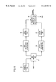
- FIG. 5 is a block diagram of interlaced coding apparatus according to one embodiment of the present invention.
- a BAB division unit 51 divides input binary shape information into BAB units of a predetermined size (e.g., 16 ⁇ 16).
- a coding type mode determining unit 52 checks correlation with respect to the input BAB and determines whether to code in units of a frame type or a field type.
- a switching unit 53 switches the BAB received from the BAB division unit 51 according to a coding type mode signal SCM produced by the coding type mode determining unit 52 . When the coding type mode signal SCM is a frame mode, the switching unit 53 switches the input BAB to a frame type coding unit 56 .
- the switching unit 53 switches the input BAB to a field type coding unit 57 .
- the SCM signal is encoded and its bitstream is sent to a multiplexer for transmitting to a decoder.
- a motion estimation unit 54 estimates motion information with respect to the input BAB from the BAB division unit 51 and a previous shape information frame.
- a motion compensation unit 55 compensates the current BAB using the motion information inputted from the motion estimation unit 54 and the previous shape information frame.
- the frame type coding unit 56 receives the BAB inputted from the BAB division unit 51 and a motion compensated BAB inputted from the motion compensation unit 55 and encodes the shape information in units of a frame type, and reconstructs it and outputs its reconstructed BAB.
- the field type coding unit 57 receives the BAB inputted from the BAB division unit 51 and a motion compensated BAB inputted from the motion compensation unit 55 and encodes the shape information in units of a field type, and reconstructs it and outputs its reconstructed BAB.
- a shape reconstructing unit 60 reconstructs the shape information frame from the reconstructed BAB received from the frame type coding unit 56 and the field type coding unit 57 .
- a previous shape memory unit 59 receives a reconstructed shape information from the shape reconstructing unit 60 and stores it. This reconstructed shape information is used as a previous shape information at encoding the next shape information.
- An overhead coding unit 58 encodes overhead information such as motion information received from the motion estimation unit 54 and the information (e.g., conversion ratio, scan type, BAB_type, and so on) necessary for reconstructing shape information at a decoder which is received from the frame type coding unit 56 and field type coding unit 57 .
- a multiplexer 61 multiplexes the coded data received from the frame type coding unit 56 and field type coding unit 57 , the coded overhead information received from the overhead coding unit 59 and the coded SCM signal.
- the binary shape information is divided into blocks of a predetermined size (e.g., 16 ⁇ 16 or 8 ⁇ 8) at the BAB division unit 51 and sent to both the coding type mode determining unit 52 and the motion estimation unit 54 .
- the coding type mode determining unit 52 calculates correlation of the shape information with respect to a top and a bottom fields forming a BAB. The following expression is used as a reference in deciding the correlation of the shape information contained in both fields.
- i is a vertical location in the BAB; j, a horizontal location in the BAB; and P (i,j) , a pixel value at the location, (i,j), in the BAB.
- P (i,j) 0
- a pixel at the corresponding location is supposed to be one of pixels representing a background
- P (i,j) 1
- a pixel at the corresponding location is supposed to be one of pixels representing an object.
- the left in the formula (1) represents a value obtained by summing up differences between each even line(top field) pixel value and its neighboring odd line(bottom field) pixel value, the pixels being at the same horizontal location.
- differences of P (0,0) and P (1,0) , P (1,0) and P (2,0) , . . . , P (0,1) and P (1,1) , P (1,1) and P (2,1) , . . . , and P (14,15) and P (15,15) are calculated and all summed up.
- the right in the formula (1) represents a value obtained by summing up differences between values of two pixels at the same horizontal location and respectively in two adjacent even lines and differences between values of two pixels at the same horizontal location and respectively in two adjacent odd lines.
- differences of P (0,0) and P (2,0) , P (2,0) and P (4,0) , . . . , P (1,0) and P (3,0) , P (3,0) and P (5,0) , and P (13, 15) and P (15,15) are calculated and all summed up.
- a coding mode signal for selecting a coding mode having a less error is sent to the switching unit 53 .
- the switching unit 53 switches the BAB from the BAB division unit 51 to the frame type coding unit 56 .
- the switching unit 53 reads the BAB from the BAB division unit 51 and sends it to the field type coding unit 57 .
- FIG. 7 is a block diagram of a coding type mode determining unit according to one embodiment of the present invention.
- a BAB memory unit 71 stores an input BAB from the BAB division unit 51 .
- An address generating unit 72 generates an address to make the BAB memory output the BAB in units of a frame to a first shape comparing unit 73 a and a second shape comparing unit 73 b or the BAB in units of a field to a third shape comparing unit 73 c and a fourth shape comparing unit 73 d .
- the first shape comparing unit 73 a compares a pair of pixels at the same horizontal location in each odd line and each consecutive even line in the frame BAB.
- the second shape comparing unit 73 b compares a pair of pixels at the same horizontal location in each even and consecutive odd line in the frame BAB.
- the third shape comparing unit 73 c compares pixels at the same horizontal location in a pair of consecutive odd lines in the BAB.
- the fourth shape comparing unit 73 d compares pixels at the same horizontal location in a pair of consecutive even lines in the BAB.
- First to fourth counting units 74 a to 74 d respectively count outputs of the first to fourth shape comparing units 73 a to 73 d .
- a first summing unit 75 a sums up the outputs of the first and second counting units 74 a and 74 b .
- a second summing unit 75 b sums up the outputs of the third and fourth counting units 74 c and 74 d .
- a frame/field mode selecting and coding unit 76 compares outputs of the first and second summing units 75 a and 75 b to decide a field or frame mode and produces the SCM signal. And the frame/field mode selecting and coding unit 76 also encode the SCM signal and outputs its bitstream to multiplexer 61 .
- a coding type mode signal SCM controls the switching unit 53 depicted in FIG. 5 and a bitstream is inputted to the multiplexer 61 depicted in FIG. 5 .
- the first shape comparing unit 73 a compares a pixel P (2,j) in the even lines (top field) with a pixel P (2i+1,j) at the same horizontal position in the consecutive odd lines (bottom field) in the input BAB stored in the BAB memory 71 , wherein “j” is one of the positive numbers from 0 to 15, and “i” is one of the positive numbers from 0 to 6. Specifically, it compares P (0,0) with P (1,0) , P (2,0) with P (3,0) , . . . , P (14,0) with P (15,0) , . . . , and P (12,15) with P (13,15) .
- the second shape comparing unit 73 b compares a pixel P (2i+1,j) in each odd line with a pixel P (2i+2,j) at the same horizontal position in each consecutive even line, wherein “j” is one of the positive numbers from 0 to 15, and “i” is one of the positive numbers from 0 to 6. Specifically, it compares P (1,0) with P (2,0) , P (3,0) with P (4,0) , . . . , P (13,0) with P (14,0) . . . , and P (13,15) with P (14,15) .
- the third shape comparing unit 73 c compares a pixel P (2i,j) in each even line with a pixel P (2i+2,j) at the same horizontal position in each consecutive even line, wherein “j” is one of the positive numbers from 0 to 15, and “i” is one of the positive numbers from 0 to 6. Specifically, it compares P (0,0) with P (2,0) , P (2,0) with P (4,0) , . . . , P (12,0) with P (14,0) , . . . , and P (12,15) with P (14,15) .
- the fourth shape comparing unit 73 d compares a pixel P (2i+1,j) in each odd line with a pixel P (2i+3,j) at the same horizontal position in each consecutive odd line, wherein “j” is one of the positive numbers from 0 to 15, and “i” is one of the positive numbers from 0 to 6. Specifically, it compares P (1,0) with P (3,0) , P (3,0) with P (5,0) , . . . , P (13,0) with P (15,0) , . . . , and P (13,15) with P (15,15) .
- the ranges of “i” and “1” can be changed in accordance with the size of the BAB.
- the size of the BAB is 16 pixels ⁇ 16 lines.
- the four counting units 74 a to 74 d perform the same operation. Each counting unit is reset whenever a new BAB is inputted thereto and increases by one when “1” is inputted. After such operation is performed with respect to whole ranges of “i” and “j”, results of each counting unit are inputted to the their corresponding summing units 75 a and 75 b.
- Values of the first and second counting units 74 a and 74 b are summed up at the first summing unit 75 a
- values of the third and fourth counting units 74 c and 74 d are summed up at the second summing unit 75 b . It is be noted that a result of the summing at the first summing unit 75 a corresponds to a sum of differences between pixels in a pair of consecutive lines in the input BAB while a result of the summing at the second summing unit 75 b corresponds to a sum of differences between pixels in a pair of consecutive lines within the same field.
- the frame/field mode selecting unit 76 decides a coding mode in favor of high correlation and generates a corresponding coding type mode signal SCM. Namely, when the result value of the first summing unit 75 a is small the SCM is set to a frame mode, and when the result value of the second summing unit 75 b is small, the SCM is set to a field mode.
- the SCM is the information necessary for decoding the shape information at a decoding unit, so it should be encoded and transmitted to a receiver.
- the decoder decodes the data representing the coding type mode at a shape information decoder and determines whether the data indicates the frame type mode where a block of the shape information is coded in units of a frame type or the field type mode where a block of the shape information is coded in units of a field type.
- a bit 0 is produced as the SCM for the frame type mode while a bit 1 is produced as the SCM for the field type mode, but the coding method for the SCM is not limited to the present invention.
- FIG. 8 is a block diagram of a shape coding type mode determining unit according to another embodiment of the present invention.
- a BAB memory unit 81 stores an input BAB from the BAB division unit 51 .
- An address generating unit 82 generates an address to make the BAB memory unit 81 output the BAB in units of a frame type to a first exclusive OR(EOR) operation unit 84 or the BAB in units of a field type to a second EOR operation unit 85 .
- the first EOR operation unit 84 performs an EOR operation with respect to pairs of pixels at the same horizontal location in consecutive line pairs within the frame BAB ( 65 ) stored in the BAB memory unit 81 .
- the second EOR operation unit 85 reads odd line field ( 66 ) and even line field ( 67 ) from the frame BAB ( 65 ) stored in the BAB memory unit 81 and performs an EOR operation with respect to pairs of pixels at the same horizontal location in consecutive line pairs within each field.
- First and second summing units 86 and 87 respectively sum up outputs of the first and second EOR operation units 84 and 85 .
- the summing units can be replaced with counting units because the first and second EOR operation units 84 and 85 output data “0” or “1”, so that the counting unit can increase a count value by one when the data “1” is inputted thereto.
- a frame/field mode selecting and coding unit 88 compares the outputs of the first and second summing units 86 and 87 to decide a field or frame type mode and generates a coding type mode signal corresponding to a result of the decision.
- a character “ ⁇ circle around (x) ⁇ ” shown in the formulas (3-1), (3-2), (3-3), and (3-4) is an operator in an EOR operation and has the following features:
- FIGS. 9 a and 9 b are block diagrams of a frame type coding unit and a field type coding unit according to the present invention.
- a context-based arithmetic encoding (CAE) method is employed, but other encoding methods can be used.
- a frame type coding unit 56 comprises a bordering unit 561 and a frame scan type and CAE unit 562
- the bordering unit 561 performs the bordering—described in detail below—of the frame BAB received from the BAB division unit 51 via the switching unit 53 .
- the frame scan type and CAE unit 562 decides a scan type, that is, determines whether to perform the CAE in horizontal or vertical direction with respect to the bordered BAB and performs the CAE.
- each value of pixels, 0 or 1 is arithmetic-encoded before transmission.
- a context template is made using neighboring pixels for construction of and reference to a probability table. For example, if the neighboring pixels in the context are all “0”, namely, background pixels, there is high probability in that a current pixel to be coded is also “0”, and if the neighboring pixels in the context are all “1”, namely, object pixels, there is high probability in that the current pixel to be coded is “1” rather than “0”. Alternatively, if the neighboring pixels in the context are all “0”, namely, background pixels, there is very low probability that the current pixel to be coded is also “1”. As illustrated, when the current pixel value is arithmetic-encoded, it is adaptively encoded by changing the probability in accordance with values of the neighboring pixels.
- the frame scan type and CAE unit 562 performs the CAE while scanning the frame BAB according to the scan type described below.
- the BAB outputted from the BAB division unit 51 is inputted to the bordering unit 561 via the switching unit 53 .
- the switching unit 53 switches the BAB to the frame type coding unit 56 or the field type coding unit 57 according to the coding type mode signal received from the coding type mode determining unit 52 .
- the bordering operation is necessary for construction of the context shown in FIGS. 10 a and 10 b when a pixel 101 , 102 , 103 to be coded is located at the border of the BAB. Specifically, when the pixel 101 in FIG.
- BAB bordering The BAB bordered at the bordering unit 561 is inputted to the frame scan type and CAE unit 562 .
- the frame scan type and CAE unit 562 performs CAE in both directions—horizontal and vertical directions, and decides the direction which shows better coding efficiency by comparing the amounts of coded bits.
- This direction for CAE a scan type.
- the decided scan type is coded at the overhead coding unit 58 and transmitted to the decoder. Coded data is inputted into the multiplexer 61 in the form of a bitstream and multiplexed at the multiplexer 61 before being transmitted to the decoder.
- Reconstructed BAB is also inputted to the shape reconstructing unit 60 .
- a field type coding unit 57 comprises a BAB field converting unit 571 , a bordering unit 572 , and a field scan type and CAE unit 573 .
- the BAB field converting unit 571 converts the frame BAB received from the BAB division unit 51 via the switching unit 53 into field BAB 66 and 67 shown in FIG. 6 b .
- the bordering unit 572 performs the bordering of the field BAB received from the BAB field converting unit 571 .
- the field scan type and CAE unit 573 determines whether to scan the bordered field BAB from the bordering unit 572 in transverse direction or longitudinal direction and performs the CAE.
- Scan type(s) decided at the field scan type and CAE unit 573 is(are) coded at the overhead coding unit 58 and transmitted to the decoder, and coded data is inputted into the multiplexer 61 and multiplexed at the multiplexer 61 before being transmitted to the decoder.
- Reconstructed field BAB is inputted to the shape reconstructing unit 60 .
- FIG. 11 is a flow chart illustrating how interlaced shape information is adaptively coded according to the present invention.
- shape information of a whole picture is divided into binary alpha blocks (BABs). Therefore, an input in the flow chart shown in FIG. 11 is the BAB and an operation of FIG. 11 is performed as many times as the number of BABs in a whole picture.
- BABs binary alpha blocks
- Motion estimation is performed by using shape information of a reference picture with respect to the BAB (S 111 ).
- One motion information per BAB can be estimated or two motion information can be estimated in units of a field type with respect to the BAB.
- a flag for indicating which motion information estimation is used should be transmitted to a receiving part.
- BAB_type an overhead of the shape information, BAB_type.
- BAB_type is encoded and the pertinent BAB coding procedure is terminated.
- CAE_type CAE_type
- the coding is performed according to the selected mode and, in addition to the coded data, the flag of one bit, CAE_type, for expressing the field CAE mode or the frame CAE mode is transmitted to the decoder.
- the CAE is performed in units of a field type and a frame type and then CAE_type can be determined in favor of less number of bits generated.
- FIG. 12 is a block diagram of shape information decoding apparatus according to the present invention.
- a demultiplexer (DEMUX) 91 demultiplexes coding data received via a transmission line.
- An overhead decoding unit 92 decodes overhead information, such as BAB_type, conversion ratio (CR), and scan type (ST), in demultiplexed data received from the demultiplexer 91 .
- a coding type mode decoding unit 93 decodes coding type mode data received from the demultiplexer 91 .
- a switching unit 94 switches coded shape information received from the demultiplexer 91 according to the coding type mode received from the coding type mode decoding unit 93 .
- a frame type decoding unit 95 decodes the shape information received via the switching unit 94 and motion-compensated, previous shape information in units of a frame type using the overhead information (BAB_type, CR, ST).
- a field type decoding unit 96 decodes the shape information received via the switching unit 94 and motion-compensated, previous shape information in units of a field type using the overhead information (BAB_type, CR, ST).
- a previous shape memory unit 97 stores previous shape information received from the shape reconstructing unit 99 .
- a motion compensation unit 98 receives motion information from the overhead decoding unit 92 and the previous shape information from the previous shape memory unit 97 and performs motion compensation with respect to the previous shape information before transmission to the frame type decoding unit 95 and the field type decoding unit 96 .
- a shape reconstructing unit 99 receives the overhead information from the overhead decoding unit 92 and the reconstructed BAB received from the frame type decoding unit 95 and the field type decoding unit 96 , and produces reconstructed shape information of a
- the overhead decoding unit 92 decodes the overheads which are contained in a bitstream inputted to the demultiplexer 91 via the transmission line and necessary for the shape information decoding and controls the decoding process with decoded overhead information.
- the overhead information includes BAB_type, CR, ST, and motion information.
- BAB_type is All — 0
- the pixels of the reconstructed BAB are set to 0 at a decoder.
- BAB_type is All — 255
- the pixels of the reconstructed BAB are set to 1 at a decoder.
- a shape coding type mode (SCM) is decoded at the coding type mode decoding unit 93 and controls the switching unit 94 .
- the bitstream outputted from the demultiplexer is inputted to and decoded at the frame type decoding unit 95 .
- the bitstream outputted from the demultiplexer is inputted to and decoded at the field type decoding unit 96 .
- the motion compensation unit 98 produces a motion compensation BAB from the reference shape information stored in the previous shape memory unit 97 using decoded motion information from the overhead decoding unit 92 .
- the motion compensated BAB is inputted to the frame type decoding unit 95 and the field type decoding unit 96 .
- the frame type decoding unit 95 and the field type decoding unit 96 each decodes the bitstream received via the swithching unit 94 and produces reconstruction BAB, using the overhead from the overhead decoding unit 92 and the motion compensated BAB received from the motion compensation unit 98 .
- the shape reconstructing unit 99 reconstructs the shape information of a whole picture using the reconstructing BAB and the overhead of the overhead decoding unit 92 .
- the reconstructed shape information is stored in the previous shape memory unit 97 and used when the next shape information is decoded.
- the shape information decoding apparatus has the coding type mode decoding unit 93 , which decodes data for expressing the SCM signal, and performs the decoding at the frame type decoding unit 95 or the field type decoding unit 96 according to the decoded SCM signal.
- FIG. 13 is a detailed block diagram of a frame type decoding unit and a field type decoding unit according to the present invention.
- Demultiplexed coded shape information outputted from the demultiplexer 91 is inputted to the frame type decoding unit 95 via the switching unit 94 when the coding type mode decoding unit 93 produces a frame mode SCM signal
- the frame type decoding unit 95 comprises a bordering unit 951 and a scan type and CAE decoding unit 952 .
- the bordering unit 951 borders pixels at the border of the BAB to construct a context when a pixel to be decoded is at the border of the BAB.
- the scan type and context-based arithmetic decoding unit 952 performs context-based arithmetic decoding while scanning the frame BAB using a scan type received from the overhead decoding unit 92 .
- the field type decoding unit 96 comprises a bordering unit 961 , a scan type and context-based arithmetic decoding unit 962 , and a BAB converting unit 963 .
- the bordering unit 961 has the same function as the bordering unit 951 other than it performs bordering with respect to the BAB in units of a field type.
- the scan type and context-based arithmetic decoding unit 962 performs the context-based arithmetic decoding while scanning the field BAB using the scan type received from the overhead decoding unit 92
- the BAB converting unit 963 converts the top field BAB and the bottom field BAB received from the scan type and context-based arithmetic decoding unit 962 into a frame BAB.
- Input information of the frame type decoding unit 95 and the field type decoding unit 96 includes the coded bitstream, a motion compensation BAB, and the overhead information received from the overhead decoding unit 92 .
- the frame type decoding unit 95 is first described in detail.
- the bordering unit 951 receives the motion compensated BAB and the bitstream and performs the bordering of adopting a neighboring pixel's value to construct the CAE template.
- the motion compensated BAB is transposed according to the scan type information among the input overheads (additional information).
- the context-based arithmetic decoding is performed on the bitstream received from the demultiplexer 91 . By decoding the BAB_type information of the overhead, IntraCAE or InterCAE is obtained.
- the context-based arithmetic decoding is performed with one of these two methods.
- a context is obtained by using the neighboring pixels and arithmetic decoding is performed with reference to the probability in the obtained context.
- the field type decoding unit 96 performs the same functions as the frame type decoding unit 97 other than that it performs the functions with respect to a field and that it reconstructs the frame BAB with the context-based arithmetic decoded field BAB at the BAB converting unit 963 .
- FIG. 14 is a block diagram of a coding apparatus for interlaced shape information according to another embodiment of the present invention.
- a motion estimation unit 54 ′ has different functions. Other components perform the same functions as those depicted in FIG. 5, so the same reference numbers are given and descriptions about them are omitted here.
- the motion estimation unit 54 ′ estimates motion using the previous shape information received from the previous shape memory unit 59 and the BAB received from the BAB division unit 51 .
- the motion estimation unit 54 ′ separately estimates the motion by each field in the BAB when the SCM signal from the coding type mode determining unit 52 is a field mode. Alternatively, when the SCM signal is a frame mode, the motion estimation unit 54 ′ performs the motion estimation with respect to a frame of the BAB.
- a result of the motion estimation is sent to the motion compensation unit 56 .
- the motion compensation unit 55 compensates the input BAB using the previous shape information received from the previous shape memory unit 59 according to the motion information received from the motion estimation unit 54 ′.
- the motion compensation unit 55 sends motion compensated BAB to both the frame type coding unit 56 and field type coding unit 57 .
- the BAB is inputted to the frame type coding unit 56 and frame type coding is performed.
- the BAB is inputted to the field type coding unit 57 and field type coding is performed.
- motion estimation is not limited to a particular method, but the apparatus depicted in FIG. 14 estimates one piece of frame motion information per BAB when the SCM is the frame type mode and it estimates two pieces of field motion information per BAB when the SCM is the field type mode.
- the most important feature of the apparatus depicted in FIG. 14 is to control the motion information with the SCM.
- This method has advantages when the motion information of the shape information is very closely related to the SCM.
- the correlation between two fields is low, namely, there is much motion of an object between two fields
- field-based motion information rather than frame-based motion information usually has an advantage. It would be most advantageous in efficient coding to select a better one of two kinds of motion information as shown in FIG. 5 .
- complexity can be reduced and it is not necessary to transmit a flag for indicating that the motion information is a field type or a frame type.
- restriction can be defined such that estimation and prediction with respect to an even (top) field should be performed against the even field of a reference picture and estimation and prediction for the odd (bottom) field should be performed against the odd field of a reference picture.
- the restriction means that the estimation and compensation of each field should use the same field of the reference shape information. In this case, transmission of the flag for indicating which field of the reference picture is used is not needed, thereby improving coding efficiency.
- FIG. 15 is a flow chart of a coding method considering a CR.
- a new step, S 115 is added.
- CR is information indicating degree of compression of the BAB. For example, if CR is 1 ⁇ 4, the BAB is compressed to 1 ⁇ 4 in both vertical and horizontal direction. Consequently, a size of the BAB is reduced to 1 ⁇ 6.
- the amount of bits generated is reduced although resulting in the lossy coding.
- FIG. 16 is a flow chart showing how a CR is determined.
- a BAB is down-sampled into 1 ⁇ 6 by setting a CR to 1 ⁇ 4, in turn, the BAB of a size 1 ⁇ 6 is up-sampled to an original size and this up-sampled original size of BAB is compared with an input BAB to calculate the number of error pixels between the two BABs (S 161 ).
- the calculated number of error pixels is compared with a predetermined threshold Error_thr (S 162 ).
- the CR is determined to be set to 1 ⁇ 4 and this data is transmitted to a decoder (S 163 ), before terminating the procedure.
- the CR When the number of error pixels exceeds the threshold Error_thr, the CR is set to 1 ⁇ 2, thus down-sampling the BAB to a size 1 ⁇ 4, and, in turn, the BAB of the size 1 ⁇ 4 is up-sampled to an original size of BAB, so that the BAB is compared with an input BAB to calculate the number of error pixels between the two BABs (S 164 ).
- the calculated number of error pixels(Error) is compared with the predetermined threshold Error_thr (S 165 ).
- the CR is determined to be set to 1 ⁇ 2 and this data is transmitted to the decoder (S 166 ), before terminating the procedure.
- the CR is determined to be set to 1 and this data is transmitted to the decoder (S 167 ).
- FIG. 17 is a flow chart showing how to determine each CR and perform coding with respect to a top and a bottom fields in a binary alpha block.
- this method further includes the steps S 175 and S 176 of independently determining CRs with respect to a top and a bottom fields in a BAB.
- the step S 115 in FIG. 15 is divided into the two steps S 175 and S 176 in FIG. 17 .
- the CR is determined with respect to a frame of the BAB and one CR per BAB is coded for transmission.
- the BAB is divided into two fields and CRs of each field are independently determined in FIG. 17 .
- the step S 175 is for the top field and the step S 176 is for the bottom field.
- the procedure disclosed in FIG. 16 can be employed as a method of obtaining the CR. In this case, two CRs for each field in the BAB should be coded, so an overhead for transmitting the CRs can result in reduction of coding efficiency.
- the larger CR between two CRs of each field is selected and a selected single CR per BAB is coded and transmitted.
- the CR of the top field may be 1 ⁇ 2 and that of the bottom field may be 1 ⁇ 4
- the CR of the BAB is determined to be set to a larger value, 1 ⁇ 2, and then the CR value 1 ⁇ 2 for the BAB is coded and transmitted.
- This method is advantageous in that the CR can be determined by each field and an overhead does not occur.
- FIGS. 15 and 17 are advantageous in facilitating the loss coding by applying the CR, but they have also a drawback that characteristics of the BAB do not considered in determining and coding the CR.
- the method depicted in FIG. 15 is efficient with respect to the frame type BAB but inefficient with respect to the field type BAB
- the method depicted in FIG. 17 is inefficient with respect to the frame type BAB but efficient with respect to the field type BAB.
- a method depicted in FIG. 18 is offered.
- FIG. 18 is a flow chart showing a method of determining a CR after deciding CAE_type.
- CAE_type is the frame CAE mode
- the CR of the BAB is determined and this data is transmitted to the decoder according to the method shown in FIG. 16 at the step S 189 .
- a single CR is determined.
- CAE type is the field CAE mode
- each CR is separately determined with respect to the top field BAB and the bottom field BAB and the CR data is transmitted to the decoder through the method shown in FIG. 16 at the respective steps S 187 and S 188 .
- the method illustrated in FIG. 18 first decides CAE_type and then determines the CR in accordance with CAE_type.
- CAE_type is the frame CAE mode
- a frame type CR is determined (S 189 ).
- CAE_type is the field CAE mode
- a field type CR is determined (S 187 and S 188 ).
- S 175 and S 176 in FIG. 17 a single CR per BAB can be selected and coded before transmission at S 187 and S 188 in FIG. 18 .
- FIG. 19 is a block diagram of a coding apparatus having a field CR determining unit according to the present invention.
- the apparatus depicted in FIG. 19 further includes a frame CR determining unit 191 and a field CR determining unit 192 .
- the frame CR determining unit 191 corresponds to an apparatus for performing the step S 189 in FIG. 18 .
- the frame CR determining unit 191 determines a CR and converts the input BAB and the motion compensated BAB in accordance with the determined CR.
- a result BABs of the conversion are inputted to the frame type coding unit 56 .
- the field CR determining unit 192 is for performing the steps S 187 and S 188 in FIG. 18 .
- the field CR determining unit 192 determines CRs and converts the input BAB and the motion compensated BAB in accordance with the determined CRs.
- a result BABs of the conversion are inputted to the field type coding unit 57 .
- FIGS. 15, 17 , and 19 additionally using the CR have been described.
- use of the CR enables the loss coding and the coding efficiency can be improved by properly selecting the CR.
- the CR can be used when deciding All — 0 or All — 255 at a BAB_type determining unit.
- This method can be applied to the lossy coding. While performing processes shown in the flow chart of FIG. 11, the input BAB which was down-sampled and then up-sampled is compared with a BAB in which all pixels have a value, 0. When the number of error pixels between the two BAB is less than or equal to a predetermined threshold, it is decided that BAB_type is All — 0. Similarly, the input BAB which was down-sampled and then up-sampled is compared with a BAB in which all pixels have a value, 1 (or 255).
- BAB_type is All — 255.
- the number of BABs where BAB_type is All — 0 or All — 255 increases, thereby reducing complexity and the amount of transmission data.
- Another method is implemented by expanding and applying the first method described above to the field type coding. After performing the operations of the first method with respect to the frame type BAB as described before, the same operations are repeated with respect to the field type BAB. Specifically, the operations are applied to each independent field and, when both fields are detected to be All — 0, BAB_type is determined to be All — 0. When both fields are detected to be All — 255, BAB_TYPE is determined to be All — 255.
- This method is advantageous in processing interlaced shape information. Because, for the interlaced shape information, BAB_type can be All — 0 in a field-based process although BAB_type is not All — 0 in a frame-based process.
- Another method is to use the same scan type (ST) for both fields and to transmit a single ST per BAB. According to this method, overhead transmission can be reduced, thereby improving the coding efficiency.
- ST scan type
- Still another method is related to a flush bit.
- a coder using both arithmetic coding and non-arithmetic coding together should transmit a flush bit after finishing the arithmetic coding and before starting the non-arithmetic coding.
- flush bits should be transmitted twice in the field type coding, compared with in the frame type coding. This reduces the coding efficiency in the field type coding.
- the arithmetic coding with respect to both fields are consecutively performed. This method allows a flush bit to be transmitted just once in the field type coding mode as in the frame type coding mode.
- the present invention selects one of the frame and field type shape coding modes according to the amounts of motion of the frame based shape information and the field-based shape information to adaptively code the interlaced shape information, thereby improving efficiency in coding the interlaced shape information.
Abstract
Description


Claims (11)

Applications Claiming Priority (4)
| Application Number | Priority Date | Filing Date | Title |
|---|---|---|---|
| KR97-49790 | 1997-09-29 | ||
| KR1019970049790A KR19990027349A (en) | 1997-09-29 | 1997-09-29 | How to convert video information |
| KR1019980000491A KR19990065274A (en) | 1998-01-10 | 1998-01-10 | Shape Information Coding Method for Progressive Scan |
| KR98-00491 | 1998-01-10 |
Publications (1)
| Publication Number | Publication Date |
|---|---|
| US6307976B1 true US6307976B1 (en) | 2001-10-23 |
Family
ID=26633104
Family Applications (1)
| Application Number | Title | Priority Date | Filing Date |
|---|---|---|---|
| US09/162,604 Expired - Lifetime US6307976B1 (en) | 1997-09-29 | 1998-09-29 | Apparatus and method of adaptively coding/decoding interlaced shaped material |
Country Status (4)
| Country | Link |
|---|---|
| US (1) | US6307976B1 (en) |
| EP (1) | EP0924932A3 (en) |
| JP (1) | JPH11177980A (en) |
| KR (1) | KR100535631B1 (en) |
Cited By (7)
| Publication number | Priority date | Publication date | Assignee | Title |
|---|---|---|---|---|
| US20030099294A1 (en) * | 2001-11-27 | 2003-05-29 | Limin Wang | Picture level adaptive frame/field coding for digital video content |
| US6584229B1 (en) * | 1999-08-30 | 2003-06-24 | Electronics And Telecommunications Research Institute | Macroblock-based object-oriented coding method of image sequence having a stationary background |
| US20040240559A1 (en) * | 2003-05-28 | 2004-12-02 | Broadcom Corporation | Context adaptive binary arithmetic code decoding engine |
| US20050259747A1 (en) * | 2004-05-21 | 2005-11-24 | Broadcom Advanced Compression Group, Llc | Context adaptive binary arithmetic code decoder for decoding macroblock adaptive field/frame coded video data |
| US20060227421A1 (en) * | 2005-04-06 | 2006-10-12 | Stover Carl A | Optical bodies including strippable boundary layers |
| US20070147503A1 (en) * | 2005-12-27 | 2007-06-28 | Toshiyuki Ikeda | Selection of encoded data, setting of encoded data, creation of recoded data, and recoding method and device |
| US20090180532A1 (en) * | 2008-01-15 | 2009-07-16 | Ximin Zhang | Picture mode selection for video transcoding |
Families Citing this family (9)
| Publication number | Priority date | Publication date | Assignee | Title |
|---|---|---|---|---|
| KR100258111B1 (en) * | 1997-10-31 | 2000-06-01 | 전주범 | Apparatus for processing adaptively coding of binary shape signal |
| KR20000021867A (en) * | 1998-09-30 | 2000-04-25 | 전주범 | Method for encoding motion vector of binary form signal |
| KR100636521B1 (en) * | 1999-10-08 | 2006-10-18 | 주식회사 팬택앤큐리텔 | Method for forming context in coding interlaced shape information adaptively |
| JP4240283B2 (en) | 2002-10-10 | 2009-03-18 | ソニー株式会社 | Decoding device and decoding method |
| KR20040035014A (en) * | 2002-10-18 | 2004-04-29 | 엘지전자 주식회사 | Method for moving picture decoding |
| KR100574943B1 (en) * | 2003-06-10 | 2006-05-02 | 삼성전자주식회사 | Method and apparatus for image transformation |
| KR100757374B1 (en) * | 2006-03-02 | 2007-09-11 | 삼성전자주식회사 | Method of compressing pixel data and pixel data compression device using the same |
| JP5500210B2 (en) * | 2012-06-22 | 2014-05-21 | ソニー株式会社 | Encoding apparatus, encoding method, and encoding program |
| EP3203744A4 (en) * | 2014-10-31 | 2017-08-30 | Samsung Electronics Co., Ltd. | Method and device for encoding or decoding image |
Citations (7)
| Publication number | Priority date | Publication date | Assignee | Title |
|---|---|---|---|---|
| US5091782A (en) | 1990-04-09 | 1992-02-25 | General Instrument Corporation | Apparatus and method for adaptively compressing successive blocks of digital video |
| US5237574A (en) * | 1988-04-08 | 1993-08-17 | Digital Equipment Corporation | Error-resilient information encoding |
| US5539466A (en) | 1991-07-30 | 1996-07-23 | Sony Corporation | Efficient coding apparatus for picture signal and decoding apparatus therefor |
| US5974184A (en) * | 1997-03-07 | 1999-10-26 | General Instrument Corporation | Intra-macroblock DC and AC coefficient prediction for interlaced digital video |
| US5973743A (en) * | 1997-12-02 | 1999-10-26 | Daewoo Electronics Co., Ltd. | Mode coding method and apparatus for use in an interlaced shape coder |
| US5991447A (en) * | 1997-03-07 | 1999-11-23 | General Instrument Corporation | Prediction and coding of bi-directionally predicted video object planes for interlaced digital video |
| US6049567A (en) * | 1997-10-14 | 2000-04-11 | Daewoo Electronics Co., Ltd. | Mode coding method in a binary shape encoding |
Family Cites Families (6)
| Publication number | Priority date | Publication date | Assignee | Title |
|---|---|---|---|---|
| NL8700565A (en) * | 1987-03-10 | 1988-10-03 | Philips Nv | TV SYSTEM IN WHICH TRANSFORMED CODING TRANSFERS DIGITIZED IMAGES FROM A CODING STATION TO A DECODING STATION. |
| JP2991833B2 (en) * | 1991-10-11 | 1999-12-20 | 松下電器産業株式会社 | Interlace scanning digital video signal encoding apparatus and method |
| KR970005831B1 (en) * | 1992-09-09 | 1997-04-21 | 대우전자 주식회사 | Image coder using adaptive frame/field change coding method |
| AU5410298A (en) * | 1996-12-12 | 1998-07-03 | Matsushita Electric Industrial Co., Ltd. | Picture encoder and picture decoder |
| KR19980066971A (en) * | 1997-01-30 | 1998-10-15 | 구자홍 | Image Coding Device with Motion Movement Detection |
| KR19990027349A (en) * | 1997-09-29 | 1999-04-15 | 김영환 | How to convert video information |
-
1998
- 1998-09-22 KR KR1019980039193A patent/KR100535631B1/en not_active IP Right Cessation
- 1998-09-29 JP JP27603398A patent/JPH11177980A/en active Pending
- 1998-09-29 EP EP19980307921 patent/EP0924932A3/en not_active Withdrawn
- 1998-09-29 US US09/162,604 patent/US6307976B1/en not_active Expired - Lifetime
Patent Citations (7)
| Publication number | Priority date | Publication date | Assignee | Title |
|---|---|---|---|---|
| US5237574A (en) * | 1988-04-08 | 1993-08-17 | Digital Equipment Corporation | Error-resilient information encoding |
| US5091782A (en) | 1990-04-09 | 1992-02-25 | General Instrument Corporation | Apparatus and method for adaptively compressing successive blocks of digital video |
| US5539466A (en) | 1991-07-30 | 1996-07-23 | Sony Corporation | Efficient coding apparatus for picture signal and decoding apparatus therefor |
| US5974184A (en) * | 1997-03-07 | 1999-10-26 | General Instrument Corporation | Intra-macroblock DC and AC coefficient prediction for interlaced digital video |
| US5991447A (en) * | 1997-03-07 | 1999-11-23 | General Instrument Corporation | Prediction and coding of bi-directionally predicted video object planes for interlaced digital video |
| US6049567A (en) * | 1997-10-14 | 2000-04-11 | Daewoo Electronics Co., Ltd. | Mode coding method in a binary shape encoding |
| US5973743A (en) * | 1997-12-02 | 1999-10-26 | Daewoo Electronics Co., Ltd. | Mode coding method and apparatus for use in an interlaced shape coder |
Non-Patent Citations (2)
| Title |
|---|
| Article: Interlaced Binary Shape Coding (S12), Sung-Moon Chun, et al. |
| MPEG4 Video Verification Model, VM 10.0, pp. 52-53, 3.4.1 "Low Pass Extrapolation (LPE) Padding Technique" 3.4.2 "Adaptive Frame/Field DCT"and 3.4.3 "DCT". |
Cited By (19)
| Publication number | Priority date | Publication date | Assignee | Title |
|---|---|---|---|---|
| US6584229B1 (en) * | 1999-08-30 | 2003-06-24 | Electronics And Telecommunications Research Institute | Macroblock-based object-oriented coding method of image sequence having a stationary background |
| US20070064801A1 (en) * | 2001-11-27 | 2007-03-22 | General Instrument Corporation | Picture Level Adaptive Frame/Field Coding for Digital Video Content |
| US7839931B2 (en) | 2001-11-27 | 2010-11-23 | General Instrument Corporation | Picture level adaptive frame/field coding for digital video content |
| US20110064141A1 (en) * | 2001-11-27 | 2011-03-17 | General Instrument Corporation | Picture Level Adaptive Frame/Field Coding for Digital Video Content |
| US7660353B2 (en) | 2001-11-27 | 2010-02-09 | General Instrument Corporation | Picture level adaptive frame/field coding for digital video content |
| US20050152454A1 (en) * | 2001-11-27 | 2005-07-14 | Limin Wang | Picture level adaptive frame/field coding for digital video content |
| US7769087B2 (en) | 2001-11-27 | 2010-08-03 | General Instruments Corporation | Picture level adaptive frame/field coding for digital video content |
| US20050117651A1 (en) * | 2001-11-27 | 2005-06-02 | Limin Wang | Picture level adaptive frame/field coding for digital video content |
| US20030099294A1 (en) * | 2001-11-27 | 2003-05-29 | Limin Wang | Picture level adaptive frame/field coding for digital video content |
| US8630350B2 (en) | 2001-11-27 | 2014-01-14 | Motorola Mobility Llc | Picture level adaptive frame/field coding for digital video content |
| US20050117649A1 (en) * | 2001-11-27 | 2005-06-02 | Limin Wang | Picture level adaptive frame/field coding for digital video content |
| US7769088B2 (en) * | 2003-05-28 | 2010-08-03 | Broadcom Corporation | Context adaptive binary arithmetic code decoding engine |
| US20040240559A1 (en) * | 2003-05-28 | 2004-12-02 | Broadcom Corporation | Context adaptive binary arithmetic code decoding engine |
| US20050259747A1 (en) * | 2004-05-21 | 2005-11-24 | Broadcom Advanced Compression Group, Llc | Context adaptive binary arithmetic code decoder for decoding macroblock adaptive field/frame coded video data |
| US20060227421A1 (en) * | 2005-04-06 | 2006-10-12 | Stover Carl A | Optical bodies including strippable boundary layers |
| US8254463B2 (en) * | 2005-12-27 | 2012-08-28 | Nec Corporation | Selection of encoded data, setting of encoded data, creation of recoded data, and recoding method and device |
| US20070147503A1 (en) * | 2005-12-27 | 2007-06-28 | Toshiyuki Ikeda | Selection of encoded data, setting of encoded data, creation of recoded data, and recoding method and device |
| US20090180532A1 (en) * | 2008-01-15 | 2009-07-16 | Ximin Zhang | Picture mode selection for video transcoding |
| US8275033B2 (en) * | 2008-01-15 | 2012-09-25 | Sony Corporation | Picture mode selection for video transcoding |
Also Published As
| Publication number | Publication date |
|---|---|
| KR19990030024A (en) | 1999-04-26 |
| EP0924932A3 (en) | 1999-12-01 |
| KR100535631B1 (en) | 2006-07-10 |
| JPH11177980A (en) | 1999-07-02 |
| EP0924932A2 (en) | 1999-06-23 |
Similar Documents
| Publication | Publication Date | Title |
|---|---|---|
| US6381277B1 (en) | Shaped information coding device for interlaced scanning video and method therefor | |
| EP1442603B1 (en) | Spatial scalable compression scheme using spatial sharpness enhancement techniques | |
| US8401079B2 (en) | Image coding apparatus, image coding method, image decoding apparatus, image decoding method and communication apparatus | |
| US6307976B1 (en) | Apparatus and method of adaptively coding/decoding interlaced shaped material | |
| US7924917B2 (en) | Method for encoding and decoding video signals | |
| JP5030591B2 (en) | Interlaced video encoding and decoding | |
| RU2307478C2 (en) | Method for compensating global movement for video images | |
| US7499495B2 (en) | Extended range motion vectors | |
| KR100964526B1 (en) | Multimedia coding techniques for transitional effects | |
| US20060153294A1 (en) | Inter-layer coefficient coding for scalable video coding | |
| KR20110028561A (en) | Video compression method | |
| NO178419B (en) | Method and apparatus for adaptively compressing successive blocks of digital video | |
| KR20060088461A (en) | Method and apparatus for deriving motion vectors of macro blocks from motion vectors of pictures of base layer when encoding/decoding video signal | |
| US20060133677A1 (en) | Method and apparatus for performing residual prediction of image block when encoding/decoding video signal | |
| GB2352918A (en) | Picture coding apparatus | |
| JP2000217103A (en) | Object unit video signal coder/decoder and its method | |
| US20060120459A1 (en) | Method for coding vector refinement information required to use motion vectors in base layer pictures when encoding video signal and method for decoding video data using such coded vector refinement information | |
| US7426311B1 (en) | Object-based coding and decoding apparatuses and methods for image signals | |
| KR100380230B1 (en) | Image codec system based on multi-resolution image | |
| US6553149B1 (en) | Shape information coding and decoding apparatus for adaptively bordering and method therefor | |
| KR100351568B1 (en) | Apparatus and method for high compression to consider edge direction of motion compensated prediction | |
| JPH01205670A (en) | Picture signal encoding system | |
| JP2003116140A (en) | Moving picture reversible coding method and its decoding method, and apparatus for the same | |
| EP3850839A1 (en) | Bitstream decoder | |
| KR100636521B1 (en) | Method for forming context in coding interlaced shape information adaptively |
Legal Events
| Date | Code | Title | Description |
|---|---|---|---|
| AS | Assignment |
Owner name: HYUNDAI ELECTRONICS IND. CO., LTD., KOREA, REPUBLI Free format text: ASSIGNMENT OF ASSIGNORS INTEREST;ASSIGNORS:CHUN, SUNG-MOON;SHIN, DONG-KYOO;MOON, JOO-HEE;REEL/FRAME:009643/0502;SIGNING DATES FROM 19980924 TO 19980925 |
|
| STCF | Information on status: patent grant |
Free format text: PATENTED CASE |
|
| FEPP | Fee payment procedure |
Free format text: PAYOR NUMBER ASSIGNED (ORIGINAL EVENT CODE: ASPN); ENTITY STATUS OF PATENT OWNER: LARGE ENTITY |
|
| AS | Assignment |
Owner name: HYNIX SEMICONDUCTOR, KOREA, REPUBLIC OF Free format text: CHANGE OF NAME;ASSIGNOR:HYUNDAI ELECTRONICS IND. CO. LTD.;REEL/FRAME:013531/0590 Effective date: 20010329 Owner name: HYUNDAI CURITEL, INC., KOREA, REPUBLIC OF Free format text: ASSIGNMENT OF ASSIGNORS INTEREST;ASSIGNOR:HYNIX SEMICONDUCTOR INC.;REEL/FRAME:013235/0032 Effective date: 20010725 |
|
| FPAY | Fee payment |
Year of fee payment: 4 |
|
| FPAY | Fee payment |
Year of fee payment: 8 |
|
| FEPP | Fee payment procedure |
Free format text: PAYER NUMBER DE-ASSIGNED (ORIGINAL EVENT CODE: RMPN); ENTITY STATUS OF PATENT OWNER: LARGE ENTITY Free format text: PAYOR NUMBER ASSIGNED (ORIGINAL EVENT CODE: ASPN); ENTITY STATUS OF PATENT OWNER: LARGE ENTITY |
|
| FPAY | Fee payment |
Year of fee payment: 12 |
|
| AS | Assignment |
Owner name: PANTECH INC., KOREA, REPUBLIC OF Free format text: DE-MERGER;ASSIGNOR:PANTECH CO., LTD.;REEL/FRAME:039981/0927 Effective date: 20151022 Owner name: CURITEL COMMUNICATIONS INC., KOREA, REPUBLIC OF Free format text: CHANGE OF NAME;ASSIGNOR:HYUNDAI CURITEL, INC.;REEL/FRAME:040149/0348 Effective date: 20020404 Owner name: PANTECH & CURITEL COMMUNICATIONS INC., KOREA, REPU Free format text: CHANGE OF NAME;ASSIGNOR:CURITEL COMMUNICATIONS INC.;REEL/FRAME:040164/0585 Effective date: 20020802 Owner name: PANTECH CO., LTD., KOREA, REPUBLIC OF Free format text: MERGER;ASSIGNOR:PANTECH & CURITEL COMMUNICATIONS INC.;REEL/FRAME:040414/0638 Effective date: 20091230 |