US6308282B1 - Apparatus and methods for providing fault tolerance of networks and network interface cards - Google Patents
Apparatus and methods for providing fault tolerance of networks and network interface cards Download PDFInfo
- Publication number
- US6308282B1 US6308282B1 US09/188,976 US18897698A US6308282B1 US 6308282 B1 US6308282 B1 US 6308282B1 US 18897698 A US18897698 A US 18897698A US 6308282 B1 US6308282 B1 US 6308282B1
- Authority
- US
- United States
- Prior art keywords
- network
- message
- node
- stand
- failure
- Prior art date
- Legal status (The legal status is an assumption and is not a legal conclusion. Google has not performed a legal analysis and makes no representation as to the accuracy of the status listed.)
- Expired - Lifetime
Links
Images


Classifications
-
- H—ELECTRICITY
- H04—ELECTRIC COMMUNICATION TECHNIQUE
- H04L—TRANSMISSION OF DIGITAL INFORMATION, e.g. TELEGRAPHIC COMMUNICATION
- H04L69/00—Network arrangements, protocols or services independent of the application payload and not provided for in the other groups of this subclass
- H04L69/40—Network arrangements, protocols or services independent of the application payload and not provided for in the other groups of this subclass for recovering from a failure of a protocol instance or entity, e.g. service redundancy protocols, protocol state redundancy or protocol service redirection
Definitions
- the present invention relates generally to network data communications.
- the present invention relates to apparatus and methods providing fault tolerance of networks and network interface cards, wherein middleware facilitates failure detection, and switching from an active channel to a stand-by channel upon detection of a failure on the active channel.
- Computer networks have become widely popular throughout business and industry. They may be used to link multiple computers within one location or across multiple sites.
- the network provides a communication channel for the transmission of data, or traffic, from one computer to another.
- Network uses are boundless and may include simple data or file transfers, remote audio or video, multimedia conferencing, industrial process control and more.
- Ethernet a local area network (LAN) specification for high-speed terminal to computer communications or computer to computer file transfers.
- the Ethernet communication protocol permits and accommodates data transfers across a bus, typically a twisted pair or coaxial cable.
- Other media for data bus exist, such as fiber optic bus or wireless bus as just two examples.
- the generic term bus will be used, regardless of media type.
- a typical LAN will have a number of nodes connected to and in communication with the LAN. Each node will have a network interface card (NIC) providing the communication link to the physical LAN through a drop to the LAN. Alternatively, several nodes may be connected to a network hub, or switch, through their respective network interface cards. In addition, multiple LANs may be bridged together to create larger networks.
- NIC network interface card
- Nodes generally comply with the OSI model, i.e., the network model of the International Standards Organization.
- the OSI model divides network communications into seven functional layers. The layers are arranged in a logical hierarchy, with each layer providing communications to the layers immediately above and below. Each OSI layer is responsible for a different network service.
- the layers are 1) Physical, 2) Data Link, 3) Network, 4) Transport, 5) Session, 6) Presentation and 7) Application.
- the first three layers provide data transmission and routing.
- the Transport and Session layers provide the interface between user applications and the hardware.
- the last three layers manage the user application.
- Other network models are well known in the art.
- Ethernet protocol provides recovery for message collision across the network
- network components such as the network interface cards, drops, hubs, switches, bridges or bus.
- Fault tolerance is thus often needed to assure continued node-to-node communications.
- One approach proposed by others is to design redundant systems relying on specialized hardware for failure detection and recovery.
- Such solutions are proprietary and vendor-dependent, making them difficult and expensive to implement.
- These hardware-oriented systems may be justified in highly critical applications, but they may not be highly portable or expandable due to their specialized nature.
- a middleware approach provides network fault tolerance over conventional Ethernet networks.
- the networks have a plurality of nodes desiring to transmit packets of data.
- Nodes of the fault-tolerant network have more than one network connection, and include nodes having multiple connections to one network and nodes having single connections to multiple networks.
- a network fault-tolerance manager oversees detection of failures and manipulation of failure recovery. Failure recovery includes redirecting data transmission of a node from a channel indicating a failure to a stand-by channel. In one embodiment, failure recovery restricts data transmission, and thus receipt, to one active channel. In another embodiment, failure recovery allows receipt of valid data packets from any connected channel. In a further embodiment, the active channel and the stand-by channel share common resources.
- the middleware comprises computer software residing above a network interface device and the device driver, yet below the system transport services and/or user applications.
- the invention provides network fault tolerance which does not require modification to existing COTS hardware and software that implement Ethernet.
- the middleware approach is transparent to applications using standard network and transport protocols, such as TCP/IP, UDP/IP and IP Multicast.
- a network node is simultaneously connected to more than one network of a multiple-network system.
- the node is provided with a software switch capable of selecting a channel on one of the networks.
- a network fault-tolerance manager performs detection of a failure on an active channel.
- the network fault-tolerance manager further provides failure recovery in manipulating the switch to select a stand-by channel.
- the node is connected to one active channel and one stand-by channel.
- a network fault-tolerance manager performs detection and reporting of a failure on a stand-by channel, in addition to detection and recovery of a failure on an active channel.
- a node is simultaneously connected to more than one network of a multiple-network system.
- the node is provided with an NIC (network interface card) for each connected network.
- the node is further provided with an NIC switch capable of selecting one of the network interface cards.
- a network fault-tolerance manager provides distributed detection of a failure on an active channel.
- the network fault-tolerance manager further provides failure recovery in manipulating the NIC switch to select the network interface card connected to a stand-by channel.
- the node is connected to one active channel and one stand-by channel.
- At least two nodes are each simultaneously connected to more than one network of a multiple-network system.
- Each node is provided with a network interface card for each connected network.
- Each node is further provided with an NIC switch capable of selecting one of the network interface cards.
- a network fault-tolerance manager provides distributed detection of a failure on an active channel.
- the network fault-tolerance manager further provides failure recovery in manipulating the NIC switch of each sending node to select the network interface card connected to a stand-by channel.
- Data packets from a sending node are passed to the stand-by channel.
- Valid data packets from the stand-by channel are passed up to higher layers by a receiving node.
- all nodes using the active channel are swapped to one stand-by channel upon detection of a failure on the active channel.
- each node is connected to one active channel and one stand-by channel.
- At least two nodes are each simultaneously connected to more than one network of a multiple-network system.
- Each node is provided with a network interface card for each connected network.
- Each node is further provided with an NIC switch capable of selecting one of the network interface cards.
- a network fault-tolerance manager provides distributed detection of a failure on an active channel.
- the network fault-tolerance manager further provides failure recovery in manipulating the NIC switch of a sending node to select the network interface card connected to a stand-by channel. It is the node that reports a failure to the network fault-tolerance manager that swaps its data traffic from the active channel to a stand-by channel. Data packets from the sending node are passed to the stand-by channel.
- Sending nodes that do not detect a failure on the active channel are allowed to continue data transmission on the active channel.
- the NIC switch of each receiving node allows receipt of data packets on each network interface card across its respective channel. Valid data packets from any connected channel are passed up to higher layers.
- the node is connected to one active channel and one stand-by channel.
- a node has multiple connections to a single fault-tolerant network.
- the node is provided with a software switch capable of selecting one of the connections to the network.
- a network fault-tolerance manager provides distributed failure detection of a failure on an active channel.
- the network fault-tolerance manager further provides failure recovery in manipulating the switch to select a stand-by channel.
- the node is connected to one active channel and one stand-by channel.
- a node has multiple connections to a single fault-tolerant network.
- the node is provided with an NIC (network interface card) for each network connection.
- the node is further provided with an NIC switch capable of selecting one of the network interface cards.
- a network fault-tolerance manager provides distributed detection of a failure on an active channel.
- the network fault-tolerance manager further provides failure recovery in manipulating the NIC switch to select the network interface card connected to a stand-by channel.
- the node is connected to one active channel and one stand-by channel.
- At least two nodes each have multiple connections to a single fault-tolerant network.
- Each node is provided with a network interface card for each network connection.
- Each node is further provided with an NIC switch capable of selecting one of the network interface cards.
- a network fault-tolerance manager provides distributed detection of a failure on an active channel.
- the network fault-tolerance manager further provides failure recovery in manipulating the NIC switch of each sending node to select the network interface card connected to a stand-by channel.
- Data packets from a sending node are passed to the stand-by channel.
- Valid data packets from the stand-by channel are passed up to higher layers by a receiving node.
- all nodes using the active channel are swapped to one stand-by channel upon detection of a failure on the active channel.
- each node is connected to one active channel and one stand-by channel.
- At least two nodes each have multiple connections to a single fault-tolerant network.
- Each node is provided with a network interface card for each network connection.
- Each node is further provided with an NIC switch capable of selecting one of the network interface cards.
- a network fault-tolerance manager provides distributed detection of a failure on an active channel.
- the network fault-tolerance manager further provides failure recovery in manipulating the NIC switch of a sending node to select the network interface card connected to a stand-by channel. It is the node that reports a failure to the network fault-tolerance manager that swaps its data traffic from the failed active channel to a stand-by channel. Data packets from the sending node are passed to the stand-by channel.
- Sending nodes that do not detect a failure on the active channel are allowed to continue data transmission on the active channel.
- the NIC switch of each receiving node allows receipt of data packets on each network interface card across its respective channel. Valid data packets from any connected channel are passed up to higher layers.
- the node is connected to one active channel and one stand-by channel.
- the single fault-tolerant network has an open ring structure and a single fault-tolerant network manager node.
- the single fault-tolerant network manager node is connected to both ends of the open ring using two network interface cards.
- the network interface cards serve in the failure detection protocol only to detect network failures, e.g., a network bus failure. In the event a network failure is detected on the single fault-tolerant network, the two network interface cards close the ring to serve application data traffic.
- a fault-tolerant network address resolution protocol automatically populates a media access control (MAC) address mapping table upon start-up of a node.
- the FTNARP obtains the MAC address of an active and stand-by network interface card.
- the FTNARP then broadcasts the information to other nodes on the active and stand-by channels.
- Receiving nodes add the information to their respective MAC address mapping tables and reply to the source node with that node's MAC address information.
- the source node receives the reply information and adds this information to its own MAC address mapping table.
- IP Internet protocol
- the IP switching function is implemented within the NIC switch, wherein the NIC switch has an IP address mapping table.
- the IP address mapping table facilitates switching the IP destination address in each frame on the sender node, and switching back the IP address at the receiver node.
- each node sends a periodic message across every connected channel.
- Receiving nodes compare the delta time in receiving the last message from the source node on the last channel after receiving the first message from the source node on a first channel.
- a failure is declared if the receiving node cannot receive the last message within an allotted time period, and the maximum number of allowed message losses is exceeded.
- failure is determined using link integrity pulse sensing.
- Link integrity pulse is a periodic pulse used to verify channel integrity.
- both failure detection modes are utilized.
- instructions for causing a processor to carry out the methods described herein are stored on a machine-readable medium.
- the machine-readable medium is contained in the node and in communication with the node.
- the machine-readable medium is in communication with the node, but not physically associated with the node.
- One advantage of the invention is that it remains compliant with the IEEE (Institute of Electrical and Electronics Engineers, Inc.) 802.3 standard. Such compliance allows the invention to be practiced on a multitude of standard Ethernet networks without requiring modification of Ethernet hardware and software, thus remaining an open system.
- the invention also enables use of any COTS cards and drivers for Ethernet and other networks.
- Use of specific vendor cards and drivers is transparent to applications, thus making the invention capable of vendor interoperability, system configuration flexibility and low cost to network users.
- the invention provides the network fault tolerance for applications using OSI network and transport protocols layered above the middleware.
- OSI network and transport protocols layered above the middleware.
- One example is the use of TCP/IP-based applications, wherein the middleware supports these applications transparently as if the applications used the TCP/IP protocol over any standard, i.e., non-fault-tolerant, network.
- FIG. 1A is a block diagram of a portion of an multiple-network Ethernet having multiple nodes incorporating one embodiment of the invention.
- FIG. 1B is a block diagram of one embodiment of a multiple-network system incorporating the invention.
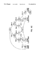
- FIG. 2 is a block diagram of one embodiment of a single fault-tolerant network incorporating the invention.
- FIG. 3A is a block diagram of an embodiment of a node incorporating one embodiment of the invention.
- FIG. 3B is a block diagram of an embodiment of a node according to one aspect of the invention.
- FIG. 4 is a block diagram of an embodiment of a node incorporating one embodiment of the invention on a specific operating system platform.
- FIG. 5 is a timeline depicting one embodiment of a message pair failure detection mode.
- FIG. 6A is a graphical representation of the interaction of a message pair table, a T skew queue and timer interrupts of one embodiment of the invention.
- FIG. 6B is a state machine diagram of a message pair failure detection mode prior to failure detection.
- FIG. 6C is a state machine diagram of a message pair failure detection mode following failure detection in one node.
- FIG. 7 is a representation of the addressing of two nodes connected to two networks incorporating one embodiment of the invention.
- FIG. 8 is a block diagram of one embodiment of a fault-tolerant network incorporating the invention and having routers.
- FIG. 9 is a flowchart of one message interrupt routine.
- FIG. 10A is a flowchart of one embodiment of the message pair processing.
- FIG. 10B is a variation on the message pair processing.
- FIG. 10C is a variation on the message pair processing.
- FIG. 11A is a flowchart of one embodiment of the T skew timer operation.
- FIG. 11B is a flowchart of one embodiment of the T skew timer operation.
- FIG. 12A is a flowchart of one embodiment of a T skew timer interrupt routine.
- FIG. 12B is a flowchart of one embodiment of a T skew timer interrupt routine.
- FIG. 13 is a flowchart of one embodiment of a routine for channel swapping.
- FIG. 14 is a flowchart of one embodiment of a message interrupt routine associated with a device swap failure recovery mode.
- FIG. 15 is a flowchart of one embodiment of a T skew timer interrupt associated with a device swap failure recovery mode.
- FIG. 16 is a flowchart of one embodiment of a fault-tolerance manager message handling routine.
- FIG. 17 is a flowchart of one embodiment of the message pair sending operation.
- FIG. 18 is a flowchart of a node start-up routine.
- FIG. 19 is a flowchart of routine for reporting a stand-by failure.
- channel is defined as the path from the network interface card of the sending node at one end to the network interface card of the receiving node at the other, and includes the drops, hubs, switches, bridges and bus.
- Two or more channels may share common resources, such a utilizing common hubs, switches, bridges and bus.
- channel resources may be mutually exclusive.
- Two channels available on a node are referred to as dual channel, although a node is not limited to having only two channels.
- FIG. 1A shows a conceptualized drawing of a simplified fault-tolerant network incorporating the invention.
- Fault-tolerant network 100 is an example of a multiple-network system.
- Fault-tolerant network 100 comprises an Ethernet bus 110 A and bus 110 B.
- the fault-tolerant network 100 further contains two or more nodes 120 which are connected to Ethernet buses 110 A and 110 B via drops 130 .
- the nodes 120 contain one or more network interface cards 170 for controlling connection to drops 130 . While network interface cards 170 are depicted as single entities, two or more network interface cards 170 may be combined as one physical card having multiple communication ports.
- FIG. 1B shows a more complete fault-tolerant network 100 of one embodiment of a multiple-network system.
- Fault-tolerant network 100 contains a primary network bus 110 A and a secondary network bus 110 B. Only one of the primary network bus 110 A and secondary network bus 110 B is utilized for data transmission by an individual node 120 at any time. Although, as discussed in relation to the device swap failure recovery mode, nodes may be utilizing multiple bus for receipt of data packets.
- Primary network bus 110 A is connected to a first network switch 240 A 1 and a second network switch 240 A 2 .
- Network switches 240 A connect the nodes 120 to the primary network bus 110 A through drops 130 A.
- FIG. 1B depicts just two network switches 240 A and six nodes 120 connected to primary network bus 110 A, although any number of nodes may be connected to any number of switches as long as those numbers remain compliant with the protocol of the network and the limit of switch port numbers. Furthermore, nodes may be connected directly to primary network bus 110 A in a manner as depicted in FIG. 1 A.
- Secondary network bus 110 B is connected to a first network switch 240 B 2 , and a second network switch 240 B 2 .
- Network switches 240 B connect the nodes 120 to the secondary network bus 110 B through drops 130 B.
- FIG. 1B depicts just two network switches 240 B and six nodes 120 connected to secondary network bus 110 B, although any number of nodes may be connected to any number of switches as long as those numbers remain compliant with the protocol of the network and the limit of switch port numbers.
- nodes may be connected directly to secondary network bus 110 A in a manner as depicted in FIG. 1 A.
- Designation of active and stand-by resources is determinable by the user with the guidance that active resources are generally associated with normal data communications and stand-by resources are generally associated with data communications in the event of a failure of some active resource.
- primary network bus 110 A may be designated for use with active channels while secondary network bus 110 B may be designated for use with stand-by channels. It will be appreciated that choice of the active channel is determinable by the user and the designations could be swapped in this example without departing from the scope of the invention. To help illustrate the concept of active and stand-by channels, a few specific examples are provided.
- the active channel from node 120 i to node 120 z is defined as the path from network interface card 170 A of node 120 i , to drop 130 A of node 120 i , to first switch 240 A 1 to primary network bus 110 A, to second switch 240 A 2 , to drop 130 A of node 120 z , to network interface card 170 A of node 120 z .
- the secondary channel from node 120 i to node 120 z is defined as the path from network interface card 170 B of node 120 i , to drop 130 B of node 120 i , to first switch 240 B 1 , to secondary network bus 110 B, to second switch 240 B 2 , to drop 130 B of node 120 z , to network interface card 170 B of node 120 z .
- Active and stand-by channels include the network interface cards at both ends of the channel.
- the active channel from node 120 j to node 120 k is defined as the path from network interface card 170 A of node 120 j , to drop 130 A of node 120 j , to first switch 240 A 1 , to drop 130 A of node 120 k , to network interface card 170 A of node 120 k .
- the secondary channel from node 120 j to node 120 k is defined as the path from network interface card 170 B of node 120 j , to drop 130 B of node 120 j , to first switch 240 B 1 , to drop 130 B of node 120 k , to network interface card 170 B of node 120 k.
- a failure of an active channel is defined as a failure of either network switch 240 A, primary network bus 110 A, any drop 130 A or any network interface card 170 A.
- a failure of a stand-by channel is defined as a failure of either network switch 240 B, secondary network bus 110 B, any drop 130 B or any network interface card 170 B. Failures on an active channel will result in failure recovery, while failures on a stand-by channel will be reported without swapping devices or channels. Note also that the definitions of active and stand-by are dynamic such that when an active channel fails and failure recovery initiates, the stand-by channel chosen for data traffic becomes an active channel.
- FIG. 2 shows a fault-tolerant network 200 of one embodiment of a single-network system.
- Fault-tolerant network 200 contains a network bus 110 .
- Network bus 110 is connected to a first network switch 240 1 , a second network switch 240 2 and a third network switch 240 3 in an open ring arrangement.
- Network switches 240 connect the nodes 120 to the network bus 110 through drops 130 A and 130 B.
- FIG. 2 depicts just three network switches 240 and four nodes 120 connected to network bus 110 , although any number of nodes may be connected to any number of switches as long as those numbers remain compliant with the protocol of the network and the limit of switch port numbers.
- nodes may be connected directly to network bus 110 in a manner similar to that depicted in FIG. 1 A.
- Fault-tolerant network 200 further contains a manager node 250 having network interface cards 170 A and 170 B.
- Network interface cards 170 A and 170 B of manager node 250 are utilized for failure detection of network failures during normal operation. If a local failure is detected, no action is taken by manager node 250 as the local failure can be overcome by swapping node communications locally to a stand-by channel.
- a local failure in fault-tolerant network 200 is characterized by a device failure affecting communications to only one network interface card 170 of a node 120 .
- a local failure between node 120 w and node 120 z could be a failure of first switch 240 1 on the active channel connected to network interface card 170 A of node 120 w .
- Swapping data communications to network interface card 170 B of node 120 w permits communication to node 120 z through second switch 240 2 .
- a network failure in fault-tolerant network 200 is characterized by a device failure affecting communications to all network interface cards 170 of a node 120 .
- a network failure between node 120 w and 120 z could be a failure of second switch 240 2 .
- Swapping communications from network interface card 170 A to 170 B of node 120 w will not suffice to restore communications with node 120 z as both channels route through second switch 240 2 .
- network interface cards 170 A and 170 B of manager node 250 close the ring, as shown by the dashed line 255 , and allow data communications through manager node 250 . With data communications served through manager node 250 , communications between node 120 w and 120 z are restored despite the failure of second switch 240 2 .
- Designation of active and stand-by resources is determinable by the user with the guidance that active resources are generally associated with normal data communications and stand-by resources are generally associated with data communications in the event of a failure of some active resource.
- network interface cards 170 A may be designated for use with active channels while network interface cards 170 B may be designated for use with stand-by channels. It will be appreciated that choice of the active channel is determinable by the user and the designations could be swapped in this example without departing from the scope of the invention.
- node 120 z is depicted as having only one network interface card 170 A. Accordingly, network interface card 170 A of node 120 z should be designated as an active device as it is the only option for normal data communications with node 120 z.
- FIG. 3 A The architecture of a node 120 containing a fault-tolerance manager according to one embodiment is generally depicted in FIG. 3 A.
- Node 120 of FIG. 3A is applicable to each fault-tolerant network structure, i.e., multiple-network systems and single fault-tolerant networks.
- FIG. 3A depicts a node 120 containing an applications layer 325 in communication with a communication API (Application Programming Interface) layer 330 .
- Applications layer 325 and communication API layer 330 are generally related to the OSI model layers 5 - 7 as shown.
- Node 120 further contains a transport/network protocol layer 335 in communication with the communication API layer 330 .
- the transport/network protocol layer relates generally to the OSI model layers 3 and 4 .
- An NIC switch 340 is in communication with the transport/network protocol layer 335 at its upper end, an NIC driver 350 A and NIC driver 350 B at its lower end, and a fault-tolerance manager 355 .
- NIC driver 350 A drives network interface card 170 A
- NIC driver 350 B drives network interface card 170 B.
- NIC switch 340 , fault-tolerance manager 355 , NIC drivers 350 A and 350 B, and network interface cards 170 A and 170 B generally relate to the OSI model layer 2 .
- Network interface card 170 A is connected to the active channel and network interface card 170 B is connected to the stand-by channel.
- Fault-tolerance manager 355 resides with each node as a stand-alone object. However, fault-tolerance manager 355 of one node communicates over the active and stand-by channels with other fault-tolerance managers of other nodes connected to the network, providing distributed failure detection and recovery capabilities. Fault-tolerance manager 355 is provided with a fault-tolerance manager configuration tool 360 for programming and monitoring its activities. Furthermore, fault-tolerance manager 355 and NIC switch 340 may be combined as a single software object.
- FIG. 3B depicts the node 120 having a processor 310 and a machine-readable medium 320 .
- Machine-readable medium 320 has instructions stored thereon for causing the processor 310 to carry out one or more of the methods disclosed herein.
- processor 310 and machine-readable medium 320 are depicted as contained within node 120 , there is no requirement that they be so contained.
- Processor 310 or machine-readable medium 320 may be in communication with node 120 , but physically detached from node 120 .
- FIG. 4 depicts a more specific embodiment of a node 120 containing a fault-tolerance manager implemented in a Microsoft® Windows NT platform.
- node 120 of this embodiment contains applications layer 325 in communication with WinSock2 layer 430 .
- WinSock2 layer 430 is in communication with transport/network protocol layer 335 .
- Transport/network protocol layer 335 contains an TCP/UDP (Transmission Control Protocol/User Datagram Protocol) layer 434 , an IP (Internet Protocol) layer 436 and NDIS (Network Data Interface Specification) protocol layer 438 .
- TCP and UDP are communication protocols for the transport layer of the OSI model.
- IP is a communication protocol dealing with the physical layer of the OSI model.
- TCP is utilized where data delivery guarantee is required, while UDP operates without guarantee of data delivery.
- NDIS protocol layer 438 provides communication to the Network Device Interface Specification (NDIS) 480 .
- NDIS Network Device Interface Specification
- NDIS 480 is in communication with the NIC switch 340 at both its upper and lower ends. This portion of NDIS 480 is termed the intermediate driver. NDIS 480 is also in communication with the NIC drivers 350 A and 350 B. This portion of NDIS 480 is termed the miniport driver. NDIS 480 generally provides communication between the transport/network protocol layer 335 and the physical layer, i.e., network buses 110 A and 110 B.
- NIC switch 340 further contains a miniport layer 442 , a protocol layer 444 and virtual drivers 446 A and 446 B.
- Miniport layer 442 provides communication to NDIS 480 at the upper end of NIC switch 340 .
- Protocol layer 444 provides communication to NDIS 480 at the lower end of NIC switch 340 .
- NIC drivers 350 A and 350 B further contain a miniport layer 452 A and 452 B, respectively.
- Miniport layer 452 A provides communication to NDIS 480 at the upper end of NIC driver 350 A.
- Miniport layer 452 B provides communication to NDIS 480 at the upper end of NIC driver 350 B.
- Fault-tolerance manager 355 is in communication with NIC switch 340 .
- Fault-tolerance manager 355 is provided with a windows driver model (WDM) 456 for communication with fault-tolerance manager configuration tool 360 .
- WDM windows driver model
- Windows driver model 456 allows easier portability of fault-tolerance manager 355 across various Windows platform.
- FIG. 4 can further be described as software objects as shown in Table 1.
- the individual software objects communicate via API calls.
- the calls associated with each object are listed in Table 1.
- Fault-tolerance manager 355 oversees distributed failure detection and failure recovery.
- Two failure detection modes will be detailed below in the context of fault-tolerant networks of the invention. Other failure detection modes will be apparent to those skilled in the art upon reading this specification. In general, any failure detection mode is sufficient if it is capable of detecting a failure of at least one network component and reporting that failure. For example, in a token-based network protocol, a network failure could be indicated by a failure to receive the token in an allotted time. It is not necessary for the failure detection mode to distinguish the type of network failure, only that it recognize one exists. It will be apparent to those skilled in the art that the descriptions below may be extrapolated to fault-tolerant networks containing more than one stand-by channel.
- the failure detection mode of fault-tolerance manager 355 utilizes message pairs.
- each node sends a pair of messages. One message of the message pair is sent across the active channel. The other message of the message pair is sent across the stand-by channel. These message pairs are sent once every T p period. In this description, these messages will be termed “I_AM_ALIVE” messages.
- each receiving node Upon receiving an “I_AM_ALIVE” message, each receiving node will allow a time T skew to receive the remaining “I_AM_LIVE” message of the message pair.
- T skew is chosen by the user to set an acceptable blackout period.
- a blackout period is the maximum amount of time network communications may be disabled by a network failure prior to detection of the failure.
- Blackout duration is generally defined by a function of T p and T skew such that blackout period equals (MaxLoss+1) * T p +T skew , where MaxLoss equal the maximum allowable losses of “I_AM_ALIVE” messages as set by the user. It should be apparent that the user has control over the acceptable blackout period, while balancing bandwidth utilization, by manipulating MaxLoss, T p and T skew .
- the receiving node will declare a failure and report the failure to fault-tolerance manager 355 in the case where MaxLoss equal zero. In a further embodiment, the receiving node will not report the failure unless the number of failed message pairs exceeds some non-zero MaxLoss. In a still further embodiment, the receiving node will report the failure after two failed message pairs, i.e., MaxLoss equals one. In these previous two embodiments, if a message pair completes successfully prior to exceeding the maximum allowable failures, the counter of failed messages is reset such that the next message pair failure does not result in a reporting of a network failure.
- FIG. 5 depicts the chronology of these “I_AM_ALIVE” messages.
- a sending node labeled as Node i sends pairs of “I_AM_ALIVE” messages to a receiving node labeled as Node j.
- the messages are sent across the active channel, shown as a solid line, and across the stand-by channel, shown as a dashed line.
- the absolute delta time of receiving a second “I_AM_ALIVE” message from one network, after receiving a first message from the other network, is compared to T skew .
- the order of receipt is not critical. It is acceptable to receive the “I_AM_ALIVE” messages in an order different from the send order without indicating a failure.
- each node maintains a message pair table for every node on the network.
- the receiving node Upon receipt of a message pair message, the receiving node checks to see if the pair of messages has been received for the sending node. If yes, the receiving node clears the counters in the sender entry in the table. If the remaining message of the message pair has not been received, and the failed message pairs exceeds MaxLoss, the receiving node places the entry of the sending node in a T skew queue as a timer event.
- the T skew queue facilitates the use of a single timer. The timer events are serialized in the T skew queue.
- T skew timer checks the entries in the queue to decide if a time-out event should be generated.
- FIG. 6A demonstrates the interaction of the message pair table 610 , the T skew queue 612 and the timer interrupts 614 .
- message pair table 610 contains fields for a sender ID, a counter for “I_AM_ALIVE” messages from the primary network (labeled Active Count), a counter for “I_AM_ALIVE” messages from the secondary network (labeled Stand-By Count), and a wait flag to indicate whether the entry is in a transient state where MaxLoss has not yet been exceeded.
- Timer event 616 has two fields. The first, labeled Ptr, is a pointer to the message pair table entry generating the timer event as shown by lines 618 .
- the second, labeled Timeout represents the current time, i.e. the time when the timer entry is generated, plus T skew If the message pair is not received prior to Timeout, the T skew timer will generate a time-out event upon checking the queue as shown by lines 620 .
- FIGS. 6B and 6C depict state machine diagrams of the failure detection mode just described.
- FIGS. 6B and 6C assume a MaxLoss of one, thus indicating a failure upon the loss of the second message pair.
- the notation is of the form (X Y Z), wherein X is the number of messages received from the active channel, Y is the number of messages received from the stand-by channel and Z indicates the channel experiencing a failure.
- Z can have three possible values in the embodiment described: 0 if no failure is detected, A if the active channel indicates a failure and B if the stand-by channel indicates a failure.
- Solid lines enclosing (X Y Z) indicate a stable state, while dashed lines indicate a transient state. As shown in FIG.
- ( 2 0 0 ) indicates a failure on the stand-by channel and ( 020 ) indicates a failure on the active channel.
- the node will report the failure to the network fault-tolerance manager and enter a failure recovery mode in accordance with the channel indicating the failure.
- FIG. 6C depicts the state machine diagram following failure on the stand-by channel. There are three possible resolutions at this stage, either the state resolves to ( 000 ) to indicate a return to a stable non-failed condition, the state continues to indicate a failure on the stand-by channel, or the state indicates a failure on the active channel. A corresponding state machine diagram following failure on the active channel will be readily apparent to one of ordinary skill in the art.
- a second failure detection mode available to fault-tolerance manager 355 is link integrity pulse detection.
- Link integrity pulse is defined by the IEEE 802 . 3 standard as being a 100 msec pulse that is transmitted by all compliant devices. This pulse is used to verify the integrity of the network cabling. A link integrity pulse failure would prompt a failure report to the fault-tolerance manager 355 .
- Fault-tolerance manager 355 is configurable through its fault-tolerance manager configuration tool 360 to selectively utilize one or more failure detection modes.
- one failure detection mode may be capable of detecting failure types that another failure detection mode is incapable of detecting.
- link integrity pulse may be incapable of detecting a partial bus failure that a message pair failure detection mode would find.
- FIG. 7 depicts two nodes 120 i and 120 j connected to a network 700 .
- Network 700 may be either a multiple-network system or a single fault-tolerant network.
- network interface card 170 Ai is associated with address ACTIVE.a
- network interface card 170 Bi is associated with network address STANDBY.b.
- network interface card 170 Aj is associated with address ACTIVE.c
- network interface card 170 Bj is associated with network address STANDBY.d.
- NIC switch 340 i utilizes the MAC address table. If the primary network is active, NIC switch 340 i directs the data packet to address ACTIVE.c on network bus 110 A. If the secondary network is active, NIC switch 340 i directs the data packet to address STANDBY.d on network bus 110 B. On receiving node 120 j , NIC switch 120 j will receive a valid data packet for either address, ACTIVE.c or STANDBY.d.
- the MAC address mapping table is automatically populated using a fault-tolerant network address resolution protocol (FTNARP).
- FTNARP fault-tolerant network address resolution protocol
- FTNARP fault-tolerant network address resolution protocol
- the invention if adaptable to fault-tolerant networks containing routers.
- An example of such a fault-tolerant network is depicted in FIG. 8 .
- the fault-tolerant network of FIG. 8 contains two nodes 120 i and 120 j connected to a primary network bus 110 A and a secondary network bus 110 B.
- Network buses 110 A and 110 B contain routers 800 A and 800 B, respectively, interposed between nodes 120 i and 120 j.
- an IP switching function is implemented within the MC switch.
- the NIC switch contains an IP address mapping table similar to the MAC address mapping table.
- the IP address mapping table includes only active destinations mapping to reduce memory usage.
- the NIC switch switches the IP destination address in each frame on the sending node, and switches back the IP address at the receiving node.
- a stand-by network which includes a node's destination default address
- that receiving node sends back an FTNARP reply packet.
- the FTNARP table can contain only active destinations mapping entries similar to the IP address mapping table.
- the receiving node responds with an FTNARP reply for the primary and secondary networks.
- the reply for the primary network presumed active in this case, is sent up to the IP layer to update the IP address mapping table.
- the reply for the secondary network is kept in the FTNARP table.
- Channel swap failure recovery mode can best be described with reference to FIG. 1B for the case of a multiple-network system and FIG. 2 for the case of a single fault-tolerant network.
- this failure recovery mode all nodes are directed to swap data transmission to a stand-by channel.
- any node 120 detects and reports a failure, all nodes will be directed to begin using the stand-by network.
- data traffic between nodes 120 i and 120 x would be through network interface card 170 Ai, primary network bus 110 A and network interface card 170 Ax before failure recovery.
- data traffic between nodes 120 i and 120 x would be through network interface card 170 Bi, secondary network bus 110 B and network interface card 170 Bx.
- any node 120 detects and reports a failure, all nodes will be directed to begin using the stand-by network.
- a logical active network and a logical stand-by network are created by utilizing a first MAC multicast group to group all active channel addresses as a logical active network, and a second MAC multicast group to group all stand-by channel addresses as a logical stand-by network
- Network interface cards 170 A and 170 B of manager node 250 are linked to close the ring of network bus 110 to facilitate communications on the logical stand-by network if the manager node 250 detects a network failure.
- An alternative failure recovery mode is the device swap mode. In this failure recovery mode, only those nodes detecting a failure will be directed to swap data transmission to the stand-by channel. All nodes accept valid data packets from either channel before and after failure recovery. Again with reference to FIG. 1B (for the case of multiple-network systems), if node 120 i detects and reports a network failure, it will be directed to begin using the stand-by channel. In this instance, data traffic from node 120 i to node 120 x would be through network interface card 170 Ai, primary network bus 110 A and network interface card 170 Ax before failure recovery. After failure recovery, data traffic from node 120 i would be directed to the stand-by channel.
- node 120 i post-failure data traffic from node 120 i to node 120 x would be through network interface card 170 Bi, secondary network bus 110 B and network interface card 170 Bx.
- Node 120 x would continue to send data using its active channel if it does not also detect the failure.
- node 120 x will accept valid data packets through either network interface card 170 Aj or network interface card 170 Bj.
- the device swap failure recovery mode works analogously in the case of the single fault-tolerant network.
- FIG. 9 depicts a flowchart of one message interrupt routine.
- a node receives a fault-tolerance manager message (FTMM) from another node at 910 .
- the fault-tolerance manager checks to see if the active channel ID of the node is the same as the active channel ID indicated by the message at 912 . If the active LAN ID of the node is different, the node runs Swap_Channel() at 914 to modify the active LAN ID of the node.
- the fault-tolerance manager acquires the spinlock of the message pair table at 916 .
- the spinlock is a resource mechanism for protecting shared resources.
- the fault-tolerance manager checks to see if an entry for the sending node exists in the message pair table at 918 . If so, the entry is updated through UpdateState() at 920 . If not, an entry is added to the table at 922 . The spinlock is released at 924 and process is repeated.
- FIG. 10A depicts a flowchart of one embodiment of the message pair table operation for the ProcessMsgPair() routine.
- an I_AM_ALIVE message is received from a sending node on the active channel at 1002 .
- the counter for the sending node's entry in the receiving node's message pair table is incremented in 1004 . If the number of messages received from the sending node on the stand-by channel is greater than zero at 1006 , both counters are cleared at 1008 and T skew , if waiting at 1012 , is reset at 1014 .
- the number of messages received from the sending node on the stand-by channel is not greater than zero at 1006 . If the number of messages received from the sending node on the stand-by channel is not greater than zero at 1006 , the number of messages from the sending node on the active channel is compared to MaxLoss at 1010 . If MaxLoss is exceeded at 1010 , a timeout is generated at 1016 to equal the current time plus T skew . This timeout entry, along with its pointer, is added to the T skew queue at 1018 , T skew is set at 1020 and the process repeats. If MaxLoss is not exceeded at 1010 , a timeout is not generated and no entry is placed in the queue.
- FIG. 110B depicts a variation on the flowchart of 110 A.
- the queue entry is checked at 1040 to see if it is in the T skew queue. If so, it is dequeued from the queue at 1044 . Furthermore, T skew is not reset regardless of whether it is waiting at 1048 .
- FIG. 10C of operation of the ProcessMsgPair() routine.
- FIG. 10A depicts a flowchart of one embodiment of the message pair table operation for the ProcessMsgPair() routine.
- an I_AM_ALIVE message is received from a sending node on the active channel at 1060 .
- the counter for the sending node's entry in the receiving node's message pair table is incremented in 1062 . If the number of messages received from the sending node on the stand-by channel is greater than zero at 1064 , the MsgFromA counter and the MsgFromB counter are cleared at 1066 and the T skew interrupt timer is reset at 1072 .
- the number of messages received from the sending node on the stand-by channel is not greater than zero at 1064 , the number of messages from the sending node on the active channel is compared to MaxLoss at 1068 . If MaxLoss is exceeded at 1068 , the interrupt timer is generated at 1070 to equal the current time plus T skew . If MaxLoss is not exceeded at 1068 , the interrupt timer is not generated. In either case, the process repeats at 1074 for receipt of a next I_AM_ALIVE message.
- FIG. 11A depicts a flowchart of one embodiment of the T skew timer operation.
- the timer waits for a timer event to be set at 1104 .
- the oldest entry in the queue is dequeued at 1106 . If the counter of messages from the active channel and the counter of messages from the stand-by channel are both at zero at 1108 , control is transferred back to 1106 . If this condition is not met, the wait flag is set to TRUE at 1110 .
- the timer waits for a reset or timeout at 1112 . If a reset occurs at 1114 , control is transferred back to 1106 . If a timeout occurs at 1114 , the T skew queue is cleared at 1116 .
- the timer determines which channel indicated the failure at 1118 . If the stand-by channel indicated a failure at 1118 , the message counters are cleared at 1122 and control is transferred back to 1104 . If the active channel indicated a failure at 1118 , SwapChannel() is called at 1120 to swap communications to the secondary network.
- FIG. 11B depicts a flowchart of one embodiment of the T skew timer operation.
- the timer waits for a timer event to be set at 1132 .
- the oldest entry in the queue is dequeued at 1134 .
- the wait flag is set to TRUE at 1134 .
- the timer waits for a reset or timeout at 1138 . If a reset occurs at 1140 , control is transferred back to 1134 .
- a timeout occurs at 1140 , the T skew queue is cleared at 1142 .
- the timer determines which channel indicated the failure at 1144 . If the stand-by channel indicated a failure at 1144 , the message counters are cleared at 1148 and control is transferred back to 1132 . If the primary network indicated a failure at 1144 , SwapChannel() is called at 1146 to swap communications to the secondary network.
- FIG. 12A depicts a flowchart of one embodiment of a T skew timer interrupt routine.
- a node i detects an expired T skew at 1202 . It then determines which channel indicates a failure at 1204 . If the stand-by channel indicates a failure at 1204 , an alarm is reported to the fault-tolerance manager at 1206 , but no change is made to the active channel. If the active channel indicates the failure at 1204 , an alarm is reported to the fault-tolerance manager at 1208 and SwapChannel() is called at 1210 to change communications from the active channel to the stand-by channel.
- FIG. 12B depicts a flowchart of another embodiment of a T skew timer interrupt routine.
- a node i detects an expired T skew at 1220 . It then determines which channel indicates a failure at 1222 . If the stand-by channel indicates a failure at 1222 , an alarm is reported to the fault-tolerance manager at 1230 , then a call is made to IndicateStandbyFailure(). If the active channel indicates the failure at 1222 , an alarm is reported to the fault-tolerance manager at 1224 and SwapChannel() is called at 1226 to change communications from the active channel to the stand-by channel. The process is repeated at 1228 .
- FIG. 13 depicts a flowchart of one embodiment of the SwapChannel() routine.
- a node toggles its adapters at 1304 to swap channels.
- the fault-tolerance manager active channel ID message is set to the active channel ID at 1306 .
- the node checks to see who initiated the swap at 1308 . If the node was directed to swap channels by another node, the process is complete and ready to repeat. If the node initiated the swap, a fault-tolerance manager SWAP_CHANNEL message is generated at 1310 and sent across the active network at 1312 by multicast.
- FIG. 14 depicts a flowchart of one embodiment of a message interrupt routine associated with a device swap failure recovery mode.
- a node receives a packet at 1402 .
- the node decides at 1404 if it is a fault-tolerance manager message or data. If data, the packet is passed up to the applications layer at 1406 . If a fault-tolerance manager message, the node further determines at 1404 if it is a DEVICE_SWAP message or an I_AM_ALIVE message. If a DEVICE_SWAP message, the MAC address mapping table of the NIC switch is updated, along with the active channel flag, at 1408 .
- the node checks the message pair table at 1410 to see if a pair of I_AM_ALIVE messages have been received. If so, the message pair table entry is cleared and the T skew timer is reset at 1414 . If a pair has not been received, the message pair table is updated and the T skew timer is set at 1412 .
- FIG. 15 depicts a flowchart of one embodiment of a T skew timer interrupt associated with a device swap failure recovery mode. If T skew has expired for a sending node i at 1502 , the receiving node checks at 1504 to see if the failure is on the active channel or the stand-by channel. If the failure is on the stand-by channel at 1504 , the receiving node issues an alarm to the fault-tolerance manager at 1510 indicating failure of the stand-by channel. If the failure is on the active channel at 1504 , the MAC address mapping table of the NIC switch is updated at 1506 .
- the update involves setting the active channel flag for node i from A to B to indicate that future communication should be directed to node i's STANDBY address.
- a fault-tolerance manager DEVICE_SWAP message is generated and sent to the sending node at 1508 .
- the receiving node then issues an alarm to the fault-tolerance manager at 1510 to indicate a failure of the active channel.
- FIG. 16 depicts a flowchart of one embodiment of a ProcessMsg() routine.
- a fault-tolerance manager message is received at 1602 . If the message is an I_AM_ALIVE message at 1604 , a ProcessMsgPair() call is made at 1610 and the process repeats at 1612 . If the message is a SWAP_CHANNEL message, the node determines if the active channel ID of the node is the same as the active channel ID of the message. If yes, no action is taken and the process repeats at 1612 .
- the node If the active channel ID of the node is different than the message, the node enters a failure recovery state at 1608 , swapping channels if the node utilizes a channel swap failure recovery mode and taking no action if the node utilizes a device swap failure recovery mode. Control is then transferred from 1608 to 1612 to repeat the process.
- FIG. 17 depicts a flowchart of one embodiment of the message pair sending operation.
- the process begins with the expiration of the T p timer at 1702 .
- the timer is reset at 1704 .
- An I_AM_ALIVE message is generated at 1706 and multicast as a fault-tolerance manager message on each channel at 1708 .
- the node then sleeps at 1710 , waiting for the T p timer to expire again and repeat the process at 1702 .
- FIG. 18 depicts a flowchart of a node start-up routine.
- the process begins at 1802 .
- the data structure, Tp timer and MaxLoss are initialized at 1804 .
- one fault-tolerance multicast group address is registered for each connected channel at 1806 .
- a single fault-tolerance multicast group address is registered for all connected channels.
- the active channel is identified at 1808 and the node enters a failure detection state at 1810 .
- FIG. 19 depicts a flowchart of the IndicateStandbyFailuer() routine.
- the process begins at 1902 .
- a fault-tolerance manager STANDBY_LAN_FAILURE message is generated at 1904 in response to a detection of a failure of a stand-by channel. Failure detection on a stand-by channel mirrors the process described for failure detection on the active channel.
- the STANDBY_LAN_FAILURE message is then multicast on the active channel at 1906 to indicate to the fault-tolerance managers of each node that the stand-by channel is unavailable for failure recovery of the active channel.
- the process is repeated at 1908 .
- the approach provides a network fault-tolerance manager for detecting network failures and manipulating a node to communicate with an active channel.
- the approach is particularly suited to Ethernet LANs.
- the network fault-tolerance manager monitors network status by utilizing message pairs, link integrity pulses or a combination of the two failure detection modes. Choice of failure detection mode is configurable in a further embodiment.
- the network fault-tolerance manager is implemented as middleware, thus enabling use of COTS devices, implementation on existing network structures and use of conventional transport/network protocols such as TCP/IP and others.
- a network fault-tolerance manager resides with each node and communicates with other network fault-tolerance managers of other nodes.
- the network fault-tolerance manager switches communication of every network node from the channel experiencing failure to a stand-by channel. In another embodiment, the network fault-tolerance manager switches communication of the node detecting a failure from the failed channel to a stand-by channel.
Abstract
Methods and apparatus for implementation of fault-tolerant networks provide a network fault-tolerance manager for detecting failures and manipulating a node to communicate with an active channel. Failure detection incorporates one or more methods, including message pair and link pulse detection. Failure recovery includes switching all node data communications to a stand-by channel or switching just those nodes detecting a failure. Communication between nodes provides the distributed detection, with detecting nodes reporting failures to their network fault-tolerance manager and the network fault-tolerance manager broadcasting the failure recovery to all nodes. The network fault-tolerance manager is middleware, residing with each node in a logical hierarchy above a physical layer of a network and below a transport layer of the network. The approach is particularly suited to Ethernet LANs and capable of using commercial off-the-shelf network components.
Description
The present invention relates generally to network data communications. In particular, the present invention relates to apparatus and methods providing fault tolerance of networks and network interface cards, wherein middleware facilitates failure detection, and switching from an active channel to a stand-by channel upon detection of a failure on the active channel.
A portion of the disclosure of this patent document contains material which is subject to copyright protection. The copyright owner has no objection to the facsimile reproduction by anyone of the patent disclosure, as it appears in the Patent and Trademark Office patent files or records, but otherwise reserves all copyright rights whatsoever. The following notice applies to the software and data as described below and in the drawings hereto: Copyright © 1998, Honeywell, Inc., All Rights Reserved.
Computer networks have become widely popular throughout business and industry. They may be used to link multiple computers within one location or across multiple sites.
The network provides a communication channel for the transmission of data, or traffic, from one computer to another. Network uses are boundless and may include simple data or file transfers, remote audio or video, multimedia conferencing, industrial process control and more.
Perhaps the most popular network protocol is Ethernet, a local area network (LAN) specification for high-speed terminal to computer communications or computer to computer file transfers. The Ethernet communication protocol permits and accommodates data transfers across a bus, typically a twisted pair or coaxial cable. Other media for data bus exist, such as fiber optic bus or wireless bus as just two examples. For convenience, the generic term bus will be used, regardless of media type.
A typical LAN will have a number of nodes connected to and in communication with the LAN. Each node will have a network interface card (NIC) providing the communication link to the physical LAN through a drop to the LAN. Alternatively, several nodes may be connected to a network hub, or switch, through their respective network interface cards. In addition, multiple LANs may be bridged together to create larger networks.
Nodes generally comply with the OSI model, i.e., the network model of the International Standards Organization. The OSI model divides network communications into seven functional layers. The layers are arranged in a logical hierarchy, with each layer providing communications to the layers immediately above and below. Each OSI layer is responsible for a different network service. The layers are 1) Physical, 2) Data Link, 3) Network, 4) Transport, 5) Session, 6) Presentation and 7) Application. The first three layers provide data transmission and routing. The Transport and Session layers provide the interface between user applications and the hardware. The last three layers manage the user application. Other network models are well known in the art.
While the Ethernet protocol provides recovery for message collision across the network, it is incapable, by itself, of recovering from failure of network components, such as the network interface cards, drops, hubs, switches, bridges or bus. Fault tolerance is thus often needed to assure continued node-to-node communications. One approach proposed by others is to design redundant systems relying on specialized hardware for failure detection and recovery. However, such solutions are proprietary and vendor-dependent, making them difficult and expensive to implement. These hardware-oriented systems may be justified in highly critical applications, but they may not be highly portable or expandable due to their specialized nature.
Accordingly, there exists a need for cost-effective apparatus and methods to provide fault tolerance that can be implemented on existing Ethernet networks using commercial-off-the-shelf (COTS) Ethernet hardware (network interface cards) and software (drivers and protocol). Such an open solution provides the benefits of low product cost, ease of use and maintenance, compliance with network standards and interoperability between networks.
A middleware approach provides network fault tolerance over conventional Ethernet networks. The networks have a plurality of nodes desiring to transmit packets of data. Nodes of the fault-tolerant network have more than one network connection, and include nodes having multiple connections to one network and nodes having single connections to multiple networks. A network fault-tolerance manager oversees detection of failures and manipulation of failure recovery. Failure recovery includes redirecting data transmission of a node from a channel indicating a failure to a stand-by channel. In one embodiment, failure recovery restricts data transmission, and thus receipt, to one active channel. In another embodiment, failure recovery allows receipt of valid data packets from any connected channel. In a further embodiment, the active channel and the stand-by channel share common resources.
The middleware comprises computer software residing above a network interface device and the device driver, yet below the system transport services and/or user applications. The invention provides network fault tolerance which does not require modification to existing COTS hardware and software that implement Ethernet. The middleware approach is transparent to applications using standard network and transport protocols, such as TCP/IP, UDP/IP and IP Multicast.
In one embodiment, a network node is simultaneously connected to more than one network of a multiple-network system. The node is provided with a software switch capable of selecting a channel on one of the networks. A network fault-tolerance manager performs detection of a failure on an active channel. The network fault-tolerance manager further provides failure recovery in manipulating the switch to select a stand-by channel. In a further embodiment, the node is connected to one active channel and one stand-by channel.
In a further embodiment, a network fault-tolerance manager performs detection and reporting of a failure on a stand-by channel, in addition to detection and recovery of a failure on an active channel.
In another embodiment, a node is simultaneously connected to more than one network of a multiple-network system. The node is provided with an NIC (network interface card) for each connected network. The node is further provided with an NIC switch capable of selecting one of the network interface cards. A network fault-tolerance manager provides distributed detection of a failure on an active channel. The network fault-tolerance manager further provides failure recovery in manipulating the NIC switch to select the network interface card connected to a stand-by channel. In a further embodiment, the node is connected to one active channel and one stand-by channel.
In a further embodiment, at least two nodes are each simultaneously connected to more than one network of a multiple-network system. Each node is provided with a network interface card for each connected network. Each node is further provided with an NIC switch capable of selecting one of the network interface cards. A network fault-tolerance manager provides distributed detection of a failure on an active channel. The network fault-tolerance manager further provides failure recovery in manipulating the NIC switch of each sending node to select the network interface card connected to a stand-by channel. Data packets from a sending node are passed to the stand-by channel. Valid data packets from the stand-by channel are passed up to higher layers by a receiving node. In this embodiment, all nodes using the active channel are swapped to one stand-by channel upon detection of a failure on the active channel. In a further embodiment, each node is connected to one active channel and one stand-by channel.
In a still further embodiment, at least two nodes are each simultaneously connected to more than one network of a multiple-network system. Each node is provided with a network interface card for each connected network. Each node is further provided with an NIC switch capable of selecting one of the network interface cards. A network fault-tolerance manager provides distributed detection of a failure on an active channel. The network fault-tolerance manager further provides failure recovery in manipulating the NIC switch of a sending node to select the network interface card connected to a stand-by channel. It is the node that reports a failure to the network fault-tolerance manager that swaps its data traffic from the active channel to a stand-by channel. Data packets from the sending node are passed to the stand-by channel. Sending nodes that do not detect a failure on the active channel are allowed to continue data transmission on the active channel. The NIC switch of each receiving node allows receipt of data packets on each network interface card across its respective channel. Valid data packets from any connected channel are passed up to higher layers. In a further embodiment, the node is connected to one active channel and one stand-by channel.
In a further embodiment, a node has multiple connections to a single fault-tolerant network. The node is provided with a software switch capable of selecting one of the connections to the network. A network fault-tolerance manager provides distributed failure detection of a failure on an active channel. The network fault-tolerance manager further provides failure recovery in manipulating the switch to select a stand-by channel.
In a further embodiment, the node is connected to one active channel and one stand-by channel.
In another embodiment, a node has multiple connections to a single fault-tolerant network. The node is provided with an NIC (network interface card) for each network connection. The node is further provided with an NIC switch capable of selecting one of the network interface cards. A network fault-tolerance manager provides distributed detection of a failure on an active channel. The network fault-tolerance manager further provides failure recovery in manipulating the NIC switch to select the network interface card connected to a stand-by channel. In a further embodiment, the node is connected to one active channel and one stand-by channel.
In a further embodiment, at least two nodes each have multiple connections to a single fault-tolerant network. Each node is provided with a network interface card for each network connection. Each node is further provided with an NIC switch capable of selecting one of the network interface cards. A network fault-tolerance manager provides distributed detection of a failure on an active channel. The network fault-tolerance manager further provides failure recovery in manipulating the NIC switch of each sending node to select the network interface card connected to a stand-by channel. Data packets from a sending node are passed to the stand-by channel. Valid data packets from the stand-by channel are passed up to higher layers by a receiving node. In this embodiment, all nodes using the active channel are swapped to one stand-by channel upon detection of a failure on the active channel. In a further embodiment, each node is connected to one active channel and one stand-by channel.
In a still further embodiment, at least two nodes each have multiple connections to a single fault-tolerant network. Each node is provided with a network interface card for each network connection. Each node is further provided with an NIC switch capable of selecting one of the network interface cards. A network fault-tolerance manager provides distributed detection of a failure on an active channel. The network fault-tolerance manager further provides failure recovery in manipulating the NIC switch of a sending node to select the network interface card connected to a stand-by channel. It is the node that reports a failure to the network fault-tolerance manager that swaps its data traffic from the failed active channel to a stand-by channel. Data packets from the sending node are passed to the stand-by channel. Sending nodes that do not detect a failure on the active channel are allowed to continue data transmission on the active channel. The NIC switch of each receiving node allows receipt of data packets on each network interface card across its respective channel. Valid data packets from any connected channel are passed up to higher layers. In a further embodiment, the node is connected to one active channel and one stand-by channel.
In another embodiment, the single fault-tolerant network has an open ring structure and a single fault-tolerant network manager node. The single fault-tolerant network manager node is connected to both ends of the open ring using two network interface cards. The network interface cards serve in the failure detection protocol only to detect network failures, e.g., a network bus failure. In the event a network failure is detected on the single fault-tolerant network, the two network interface cards close the ring to serve application data traffic.
In one embodiment, a fault-tolerant network address resolution protocol (FTNARP) automatically populates a media access control (MAC) address mapping table upon start-up of a node. The FTNARP obtains the MAC address of an active and stand-by network interface card. The FTNARP then broadcasts the information to other nodes on the active and stand-by channels. Receiving nodes add the information to their respective MAC address mapping tables and reply to the source node with that node's MAC address information. The source node receives the reply information and adds this information to its own MAC address mapping table.
In another embodiment, Internet protocol (IP) switching is provided for networks containing routers. The IP switching function is implemented within the NIC switch, wherein the NIC switch has an IP address mapping table. The IP address mapping table facilitates switching the IP destination address in each frame on the sender node, and switching back the IP address at the receiver node.
In a further embodiment, each node sends a periodic message across every connected channel. Receiving nodes compare the delta time in receiving the last message from the source node on the last channel after receiving the first message from the source node on a first channel. A failure is declared if the receiving node cannot receive the last message within an allotted time period, and the maximum number of allowed message losses is exceeded. In a still further embodiment, failure is determined using link integrity pulse sensing. Link integrity pulse is a periodic pulse used to verify channel integrity. In yet a further embodiment, both failure detection modes are utilized.
In another embodiment of the invention, instructions for causing a processor to carry out the methods described herein are stored on a machine-readable medium. In a further embodiment of the invention, the machine-readable medium is contained in the node and in communication with the node. In yet another embodiment of the invention, the machine-readable medium is in communication with the node, but not physically associated with the node.
One advantage of the invention is that it remains compliant with the IEEE (Institute of Electrical and Electronics Engineers, Inc.) 802.3 standard. Such compliance allows the invention to be practiced on a multitude of standard Ethernet networks without requiring modification of Ethernet hardware and software, thus remaining an open system.
As a software approach, the invention also enables use of any COTS cards and drivers for Ethernet and other networks. Use of specific vendor cards and drivers is transparent to applications, thus making the invention capable of vendor interoperability, system configuration flexibility and low cost to network users.
Furthermore, the invention provides the network fault tolerance for applications using OSI network and transport protocols layered above the middleware. One example is the use of TCP/IP-based applications, wherein the middleware supports these applications transparently as if the applications used the TCP/IP protocol over any standard, i.e., non-fault-tolerant, network.
FIG. 1A is a block diagram of a portion of an multiple-network Ethernet having multiple nodes incorporating one embodiment of the invention.
FIG. 1B is a block diagram of one embodiment of a multiple-network system incorporating the invention.
FIG. 2 is a block diagram of one embodiment of a single fault-tolerant network incorporating the invention.
FIG. 3A is a block diagram of an embodiment of a node incorporating one embodiment of the invention.
FIG. 3B is a block diagram of an embodiment of a node according to one aspect of the invention.
FIG. 4 is a block diagram of an embodiment of a node incorporating one embodiment of the invention on a specific operating system platform.
FIG. 5 is a timeline depicting one embodiment of a message pair failure detection mode.
FIG. 6A is a graphical representation of the interaction of a message pair table, a Tskew queue and timer interrupts of one embodiment of the invention.
FIG. 6B is a state machine diagram of a message pair failure detection mode prior to failure detection.
FIG. 6C is a state machine diagram of a message pair failure detection mode following failure detection in one node.
FIG. 7 is a representation of the addressing of two nodes connected to two networks incorporating one embodiment of the invention.
FIG. 8 is a block diagram of one embodiment of a fault-tolerant network incorporating the invention and having routers.
FIG. 9 is a flowchart of one message interrupt routine.
FIG. 10A is a flowchart of one embodiment of the message pair processing.
FIG. 10B is a variation on the message pair processing.
FIG. 10C is a variation on the message pair processing.
FIG. 11A is a flowchart of one embodiment of the Tskew timer operation.
FIG. 11B is a flowchart of one embodiment of the Tskew timer operation.
FIG. 12A is a flowchart of one embodiment of a Tskew timer interrupt routine.
FIG. 12B is a flowchart of one embodiment of a Tskew timer interrupt routine.
FIG. 13 is a flowchart of one embodiment of a routine for channel swapping.
FIG. 14 is a flowchart of one embodiment of a message interrupt routine associated with a device swap failure recovery mode.
FIG. 15 is a flowchart of one embodiment of a Tskew timer interrupt associated with a device swap failure recovery mode.
FIG. 16 is a flowchart of one embodiment of a fault-tolerance manager message handling routine.
FIG. 17 is a flowchart of one embodiment of the message pair sending operation.
FIG. 18 is a flowchart of a node start-up routine.
FIG. 19 is a flowchart of routine for reporting a stand-by failure.
In the following detailed description, reference is made to the accompanying drawings which form a part hereof, and in which is shown by way of illustration specific embodiments in which the invention may be practiced. These embodiments are described in sufficient detail to enable those skilled in the art to practice the invention, and it is to be understood that other embodiments may be utilized and that structural, logical and electrical changes may be made without departing from the spirit and scope of the invention. The following detailed description is, therefore, not to be taken in a limiting sense, and the scope of the invention is defined by the appended claims. Like numbers in the figures refer to like components, which should be apparent from the context of use.
The following detailed description is drafted in the context of an Ethernet LAN it will be apparent to those skilled in the art that the approach is adaptable to other network protocols and other network configurations.
The term channel is defined as the path from the network interface card of the sending node at one end to the network interface card of the receiving node at the other, and includes the drops, hubs, switches, bridges and bus. Two or more channels may share common resources, such a utilizing common hubs, switches, bridges and bus. Alternatively, channel resources may be mutually exclusive. Two channels available on a node are referred to as dual channel, although a node is not limited to having only two channels.
The detailed description generally begins with a discussion of network devices and their architecture, followed by a discussion of failure detection modes. Address management is discussed as a preface to failure recovery. Failure recovery is drafted in the context of what is referred to herein as a channel swap mode and a device swap mode. Finally, various exemplary implementations of the concepts are disclosed.
Devices and Architecture
FIG. 1A shows a conceptualized drawing of a simplified fault-tolerant network incorporating the invention. Fault-tolerant network 100 is an example of a multiple-network system. Fault-tolerant network 100 comprises an Ethernet bus 110A and bus 110B. The fault-tolerant network 100 further contains two or more nodes 120 which are connected to Ethernet buses 110A and 110B via drops 130. The nodes 120 contain one or more network interface cards 170 for controlling connection to drops 130. While network interface cards 170 are depicted as single entities, two or more network interface cards 170 may be combined as one physical card having multiple communication ports.
FIG. 1B shows a more complete fault-tolerant network 100 of one embodiment of a multiple-network system. Fault-tolerant network 100 contains a primary network bus 110A and a secondary network bus 110B. Only one of the primary network bus 110A and secondary network bus 110B is utilized for data transmission by an individual node 120 at any time. Although, as discussed in relation to the device swap failure recovery mode, nodes may be utilizing multiple bus for receipt of data packets. Primary network bus 110A is connected to a first network switch 240A1 and a second network switch 240A2. Network switches 240A connect the nodes 120 to the primary network bus 110A through drops 130A. FIG. 1B depicts just two network switches 240A and six nodes 120 connected to primary network bus 110A, although any number of nodes may be connected to any number of switches as long as those numbers remain compliant with the protocol of the network and the limit of switch port numbers. Furthermore, nodes may be connected directly to primary network bus 110A in a manner as depicted in FIG. 1A.
Designation of active and stand-by resources is determinable by the user with the guidance that active resources are generally associated with normal data communications and stand-by resources are generally associated with data communications in the event of a failure of some active resource. As an example, primary network bus 110A may be designated for use with active channels while secondary network bus 110B may be designated for use with stand-by channels. It will be appreciated that choice of the active channel is determinable by the user and the designations could be swapped in this example without departing from the scope of the invention. To help illustrate the concept of active and stand-by channels, a few specific examples are provided.
In reference to FIG. 1B, the active channel from node 120 i to node 120 z is defined as the path from network interface card 170A of node 120 i, to drop 130A of node 120 i, to first switch 240A1 to primary network bus 110A, to second switch 240A2, to drop 130A of node 120 z, to network interface card 170A of node 120 z. The secondary channel from node 120 i to node 120 z is defined as the path from network interface card 170B of node 120 i, to drop 130B of node 120 i, to first switch 240B1, to secondary network bus 110B, to second switch 240B2, to drop 130B of node 120 z, to network interface card 170B of node 120 z. Active and stand-by channels include the network interface cards at both ends of the channel.
Similarly, the active channel from node 120 j to node 120 k is defined as the path from network interface card 170A of node 120 j, to drop 130A of node 120 j, to first switch 240A1, to drop 130A of node 120 k, to network interface card 170A of node 120 k. The secondary channel from node 120 j to node 120 k is defined as the path from network interface card 170B of node 120 j, to drop 130B of node 120 j, to first switch 240B1, to drop 130B of node 120 k, to network interface card 170B of node 120 k.
In reference to FIG. 1B and the preceding definitions, a failure of an active channel is defined as a failure of either network switch 240A, primary network bus 110A, any drop 130A or any network interface card 170A. Likewise, a failure of a stand-by channel is defined as a failure of either network switch 240B, secondary network bus 110B, any drop 130B or any network interface card 170B. Failures on an active channel will result in failure recovery, while failures on a stand-by channel will be reported without swapping devices or channels. Note also that the definitions of active and stand-by are dynamic such that when an active channel fails and failure recovery initiates, the stand-by channel chosen for data traffic becomes an active channel.
FIG. 2 shows a fault-tolerant network 200 of one embodiment of a single-network system. Fault-tolerant network 200 contains a network bus 110. Network bus 110 is connected to a first network switch 240 1, a second network switch 240 2 and a third network switch 240 3 in an open ring arrangement. Network switches 240 connect the nodes 120 to the network bus 110 through drops 130A and 130B. FIG. 2 depicts just three network switches 240 and four nodes 120 connected to network bus 110, although any number of nodes may be connected to any number of switches as long as those numbers remain compliant with the protocol of the network and the limit of switch port numbers. Furthermore, nodes may be connected directly to network bus 110 in a manner similar to that depicted in FIG. 1A.
Fault-tolerant network 200 further contains a manager node 250 having network interface cards 170A and 170B. Network interface cards 170A and 170B of manager node 250 are utilized for failure detection of network failures during normal operation. If a local failure is detected, no action is taken by manager node 250 as the local failure can be overcome by swapping node communications locally to a stand-by channel. A local failure in fault-tolerant network 200 is characterized by a device failure affecting communications to only one network interface card 170 of a node 120. For example, a local failure between node 120w and node 120 z could be a failure of first switch 240 1 on the active channel connected to network interface card 170A of node 120 w. Swapping data communications to network interface card 170B of node 120 w permits communication to node 120 z through second switch 240 2.
If a network failure is detected, locally swapping data communications to a stand-by channel is insufficient to restore communications. A network failure in fault-tolerant network 200 is characterized by a device failure affecting communications to all network interface cards 170 of a node 120. For example, a network failure between node 120 w and 120 z could be a failure of second switch 240 2. Swapping communications from network interface card 170A to 170B of node 120 w will not suffice to restore communications with node 120 z as both channels route through second switch 240 2. In this instance, network interface cards 170A and 170B of manager node 250 close the ring, as shown by the dashed line 255, and allow data communications through manager node 250. With data communications served through manager node 250, communications between node 120 w and 120 z are restored despite the failure of second switch 240 2.
Designation of active and stand-by resources, i.e., physical network components, is determinable by the user with the guidance that active resources are generally associated with normal data communications and stand-by resources are generally associated with data communications in the event of a failure of some active resource. As an example, network interface cards 170A may be designated for use with active channels while network interface cards 170B may be designated for use with stand-by channels. It will be appreciated that choice of the active channel is determinable by the user and the designations could be swapped in this example without departing from the scope of the invention. However, it should be noted that node 120 z is depicted as having only one network interface card 170A. Accordingly, network interface card 170A of node 120 z should be designated as an active device as it is the only option for normal data communications with node 120 z.
The architecture of a node 120 containing a fault-tolerance manager according to one embodiment is generally depicted in FIG. 3A. Node 120 of FIG. 3A is applicable to each fault-tolerant network structure, i.e., multiple-network systems and single fault-tolerant networks. FIG. 3A depicts a node 120 containing an applications layer 325 in communication with a communication API (Application Programming Interface) layer 330. Applications layer 325 and communication API layer 330 are generally related to the OSI model layers 5-7 as shown. Node 120 further contains a transport/network protocol layer 335 in communication with the communication API layer 330. The transport/network protocol layer relates generally to the OSI model layers 3 and 4. An NIC switch 340 is in communication with the transport/network protocol layer 335 at its upper end, an NIC driver 350A and NIC driver 350B at its lower end, and a fault-tolerance manager 355. NIC driver 350A drives network interface card 170A and NIC driver 350B drives network interface card 170B. NIC switch 340, fault-tolerance manager 355, NIC drivers 350A and 350B, and network interface cards 170A and 170B generally relate to the OSI model layer 2. Network interface card 170A is connected to the active channel and network interface card 170B is connected to the stand-by channel.
Fault-tolerance manager 355 resides with each node as a stand-alone object. However, fault-tolerance manager 355 of one node communicates over the active and stand-by channels with other fault-tolerance managers of other nodes connected to the network, providing distributed failure detection and recovery capabilities. Fault-tolerance manager 355 is provided with a fault-tolerance manager configuration tool 360 for programming and monitoring its activities. Furthermore, fault-tolerance manager 355 and NIC switch 340 may be combined as a single software object.
FIG. 3B depicts the node 120 having a processor 310 and a machine-readable medium 320. Machine-readable medium 320 has instructions stored thereon for causing the processor 310 to carry out one or more of the methods disclosed herein. Although processor 310 and machine-readable medium 320 are depicted as contained within node 120, there is no requirement that they be so contained. Processor 310 or machine-readable medium 320 may be in communication with node 120, but physically detached from node 120.
FIG. 4 depicts a more specific embodiment of a node 120 containing a fault-tolerance manager implemented in a Microsoft® Windows NT platform. With reference to FIG. 4, node 120 of this embodiment contains applications layer 325 in communication with WinSock2 layer 430. WinSock2 layer 430 is in communication with transport/network protocol layer 335. Transport/network protocol layer 335 contains an TCP/UDP (Transmission Control Protocol/User Datagram Protocol) layer 434, an IP (Internet Protocol) layer 436 and NDIS (Network Data Interface Specification) protocol layer 438. TCP and UDP are communication protocols for the transport layer of the OSI model. IP is a communication protocol dealing with the physical layer of the OSI model. TCP is utilized where data delivery guarantee is required, while UDP operates without guarantee of data delivery. NDIS protocol layer 438 provides communication to the Network Device Interface Specification (NDIS) 480.
Fault-tolerance manager 355 is in communication with NIC switch 340. Fault-tolerance manager 355 is provided with a windows driver model (WDM) 456 for communication with fault-tolerance manager configuration tool 360. Windows driver model 456 allows easier portability of fault-tolerance manager 355 across various Windows platform.
The various components in FIG. 4 can further be described as software objects as shown in Table 1. The individual software objects communicate via API calls. The calls associated with each object are listed in Table 1.
| TABLE 1 |
| Software Objects and API Calls |
| Object | Responsibility | API |
| IP | a) | direct communication | MPSendPackets(Adapter, |
| Layer | with the physical layer; | PacketArray, | |
| 436 | NumberOfPackets) | ||
| NIC | a) | communicate with the | CLReceiveIndication(Adapter, |
| Driver | physical layer; | MacReceiveContext, | |
| 350 | HeaderBuffer, | ||
| b) | route packets to IP Layer | HeaderBufferSize, | |
| 436 or |
LookaheadBuffer, | ||
| pending upon | LookaheadBufferSize, | ||
| packet format | PacketSize) | ||
| ReceiveDelivery(Adapter, | |||
| Buffer) | |||
| FTM | a) | perform distributed | FTMSend(dest, type, data, |
| 355 | failure detection; | Datalength, Adapter) | |
| b) | direct distributed failure | ProcessMsg(Msg) | |
| recovery | InitFTM( ) | ||
| AmIFirst( ) | |||
| FTMTskewInterrupt( ) | |||
| FTMTpInterrupt( ) | |||
| SetParameters( ) | |||
| ReportChannelStatus( ) | |||
| ForceChannel(Channel_X) | |||
| FTM | a) | provide programming of | ReportNetworkStatus(data) |
| configur- | |
StartTest(data) | |
| ation | from |
ReportTestResult(data) | |
| tool | Setparameters(data) | ||
| 360 | |||
| NIC | a) | direct selection | FTMProcessMsg(Content) |
| Switch | of the active | AnnounceAddr( ) | |
| 340 | network as deter- | UpdateAddr( ) | |
| mined by |
Send(Packet, Adapter) | ||
| IndicateReceive(Packet) | |||
| SwapChannel( ) | |||
| ForceChannel(Channel_X) | |||
Failure Detection
Fault-tolerance manager 355 oversees distributed failure detection and failure recovery. Two failure detection modes will be detailed below in the context of fault-tolerant networks of the invention. Other failure detection modes will be apparent to those skilled in the art upon reading this specification. In general, any failure detection mode is sufficient if it is capable of detecting a failure of at least one network component and reporting that failure. For example, in a token-based network protocol, a network failure could be indicated by a failure to receive the token in an allotted time. It is not necessary for the failure detection mode to distinguish the type of network failure, only that it recognize one exists. It will be apparent to those skilled in the art that the descriptions below may be extrapolated to fault-tolerant networks containing more than one stand-by channel.
In one embodiment, the failure detection mode of fault-tolerance manager 355 utilizes message pairs. In this embodiment, each node sends a pair of messages. One message of the message pair is sent across the active channel. The other message of the message pair is sent across the stand-by channel. These message pairs are sent once every Tp period. In this description, these messages will be termed “I_AM_ALIVE” messages.
Upon receiving an “I_AM_ALIVE” message, each receiving node will allow a time Tskew to receive the remaining “I_AM_LIVE” message of the message pair. Tskew is chosen by the user to set an acceptable blackout period. A blackout period is the maximum amount of time network communications may be disabled by a network failure prior to detection of the failure. Blackout duration is generally defined by a function of Tp and Tskew such that blackout period equals (MaxLoss+1) * Tp+Tskew, where MaxLoss equal the maximum allowable losses of “I_AM_ALIVE” messages as set by the user. It should be apparent that the user has control over the acceptable blackout period, while balancing bandwidth utilization, by manipulating MaxLoss, Tp and Tskew.
If the second “I_AM_ALIVE” message is not received within time Tskew, the receiving node will declare a failure and report the failure to fault-tolerance manager 355 in the case where MaxLoss equal zero. In a further embodiment, the receiving node will not report the failure unless the number of failed message pairs exceeds some non-zero MaxLoss. In a still further embodiment, the receiving node will report the failure after two failed message pairs, i.e., MaxLoss equals one. In these previous two embodiments, if a message pair completes successfully prior to exceeding the maximum allowable failures, the counter of failed messages is reset such that the next message pair failure does not result in a reporting of a network failure.
FIG. 5 depicts the chronology of these “I_AM_ALIVE” messages. A sending node labeled as Node i sends pairs of “I_AM_ALIVE” messages to a receiving node labeled as Node j. The messages are sent across the active channel, shown as a solid line, and across the stand-by channel, shown as a dashed line. The absolute delta time of receiving a second “I_AM_ALIVE” message from one network, after receiving a first message from the other network, is compared to Tskew. As shown, in FIG. 5, the order of receipt is not critical. It is acceptable to receive the “I_AM_ALIVE” messages in an order different from the send order without indicating a failure.
To manage the message pair failure detection mode, each node maintains a message pair table for every node on the network. Upon receipt of a message pair message, the receiving node checks to see if the pair of messages has been received for the sending node. If yes, the receiving node clears the counters in the sender entry in the table. If the remaining message of the message pair has not been received, and the failed message pairs exceeds MaxLoss, the receiving node places the entry of the sending node in a Tskew queue as a timer event. The Tskew queue facilitates the use of a single timer. The timer events are serialized in the Tskew queue. When a timer is set for an entry, a pointer to the entry and a timeout value are appended to the queue of the Tskew timer. The Tskew timer checks the entries in the queue to decide if a time-out event should be generated.
FIG. 6A demonstrates the interaction of the message pair table 610, the Tskew queue 612 and the timer interrupts 614. As shown, message pair table 610 contains fields for a sender ID, a counter for “I_AM_ALIVE” messages from the primary network (labeled Active Count), a counter for “I_AM_ALIVE” messages from the secondary network (labeled Stand-By Count), and a wait flag to indicate whether the entry is in a transient state where MaxLoss has not yet been exceeded. Timer event 616 has two fields. The first, labeled Ptr, is a pointer to the message pair table entry generating the timer event as shown by lines 618. The second, labeled Timeout, represents the current time, i.e. the time when the timer entry is generated, plus Tskew If the message pair is not received prior to Timeout, the Tskew timer will generate a time-out event upon checking the queue as shown by lines 620.
FIGS. 6B and 6C depict state machine diagrams of the failure detection mode just described. FIGS. 6B and 6C assume a MaxLoss of one, thus indicating a failure upon the loss of the second message pair. The notation is of the form (X Y Z), wherein X is the number of messages received from the active channel, Y is the number of messages received from the stand-by channel and Z indicates the channel experiencing a failure. Z can have three possible values in the embodiment described: 0 if no failure is detected, A if the active channel indicates a failure and B if the stand-by channel indicates a failure. Solid lines enclosing (X Y Z) indicate a stable state, while dashed lines indicate a transient state. As shown in FIG. 6B, (2 0 0) indicates a failure on the stand-by channel and (020) indicates a failure on the active channel. In both of these failure cases, the node will report the failure to the network fault-tolerance manager and enter a failure recovery mode in accordance with the channel indicating the failure.
FIG. 6C depicts the state machine diagram following failure on the stand-by channel. There are three possible resolutions at this stage, either the state resolves to (000) to indicate a return to a stable non-failed condition, the state continues to indicate a failure on the stand-by channel, or the state indicates a failure on the active channel. A corresponding state machine diagram following failure on the active channel will be readily apparent to one of ordinary skill in the art.
A second failure detection mode available to fault-tolerance manager 355 is link integrity pulse detection. Link integrity pulse is defined by the IEEE 802.3 standard as being a 100 msec pulse that is transmitted by all compliant devices. This pulse is used to verify the integrity of the network cabling. A link integrity pulse failure would prompt a failure report to the fault-tolerance manager 355.
Fault-tolerance manager 355 is configurable through its fault-tolerance manager configuration tool 360 to selectively utilize one or more failure detection modes. In simple networks with only one hub or switch, it may be desirable to rely exclusively on link integrity pulse detection as the failure detection mode, thus eliminating the need to generate, send and monitor “I_AM_ALIVE” messages. However, it should be noted that one failure detection mode may be capable of detecting failure types that another failure detection mode is incapable of detecting. For example, link integrity pulse may be incapable of detecting a partial bus failure that a message pair failure detection mode would find.
Address Management
An NIC switch must deal with multiple network addresses. NIC switch 340 utilizes a MAC address table to resolve such address issues. To illustrate this concept, we will refer to FIG. 7. FIG. 7 depicts two nodes 120 i and 120 j connected to a network 700. Network 700 may be either a multiple-network system or a single fault-tolerant network. With reference to node 120 i, network interface card 170Ai is associated with address ACTIVE.a and network interface card 170Bi is associated with network address STANDBY.b. With reference to node 120 j, network interface card 170Aj is associated with address ACTIVE.c and network interface card 170Bj is associated with network address STANDBY.d. Now with reference to Table 2, if node 120 i desires to send a data packet to node 120 j and addressed to ACTIVE.c, NIC switch 340 i utilizes the MAC address table. If the primary network is active, NIC switch 340 i directs the data packet to address ACTIVE.c on network bus 110A. If the secondary network is active, NIC switch 340 i directs the data packet to address STANDBY.d on network bus 110B. On receiving node 120 j, NIC switch 120 j will receive a valid data packet for either address, ACTIVE.c or STANDBY.d.
| TABLE 2 |
| MAC Address Mapping Table |
| Destination | ||
| Node ID | Active Channel Address | Stand-By Channel Address |
| i | ACTIVE.a | STANDBY.b |
| j | ACTIVE.c | STANDBY.d |
The MAC address mapping table is automatically populated using a fault-tolerant network address resolution protocol (FTNARP). As a network node initializes, it broadcasts its MAC addresses across the fault-tolerant network using a AnnounceAddr() API call. Each receiving node will add this FTNARP information to its MAC address mapping table using a UpdateAddr() API call. Each receiving node will further reply to the source node with its own MAC addresses if sending node's information did not previously exist in the receiving node's MAC address mapping table. The source node will then populate its MAC address mapping table as a result of these reply addresses.
The invention if adaptable to fault-tolerant networks containing routers. An example of such a fault-tolerant network is depicted in FIG. 8. The fault-tolerant network of FIG. 8 contains two nodes 120 i and 120 j connected to a primary network bus 110A and a secondary network bus 110B. Network buses 110A and 110B contain routers 800A and 800B, respectively, interposed between nodes 120 i and 120 j.
In this embodiment containing routers, an IP switching function is implemented within the MC switch. The NIC switch contains an IP address mapping table similar to the MAC address mapping table. The IP address mapping table, however, includes only active destinations mapping to reduce memory usage.
Using the IP address mapping table, the NIC switch switches the IP destination address in each frame on the sending node, and switches back the IP address at the receiving node. Upon receiving an FTNARP packet via a stand-by network which includes a node's destination default address, that receiving node sends back an FTNARP reply packet. In order to optimize kernel memory usage, the FTNARP table can contain only active destinations mapping entries similar to the IP address mapping table. In this case, when a node receives an FTNARP packet from a source node, the receiving node responds with an FTNARP reply for the primary and secondary networks. The reply for the primary network, presumed active in this case, is sent up to the IP layer to update the IP address mapping table. The reply for the secondary network is kept in the FTNARP table.
Failure Recovery Channel Swap Mode
Channel swap failure recovery mode can best be described with reference to FIG. 1B for the case of a multiple-network system and FIG. 2 for the case of a single fault-tolerant network. In this failure recovery mode, all nodes are directed to swap data transmission to a stand-by channel.
With reference to FIG. 1B, if any node 120 detects and reports a failure, all nodes will be directed to begin using the stand-by network. In this instance, data traffic between nodes 120 i and 120 x would be through network interface card 170Ai, primary network bus 110A and network interface card 170Ax before failure recovery. After failure recovery, data traffic between nodes 120 i and 120 x would be through network interface card 170Bi, secondary network bus 110B and network interface card 170Bx.
With reference to FIG. 2, if any node 120 detects and reports a failure, all nodes will be directed to begin using the stand-by network. However, there is no physical stand-by network in the case of fault-tolerant network 200. In this configuration, a logical active network and a logical stand-by network are created by utilizing a first MAC multicast group to group all active channel addresses as a logical active network, and a second MAC multicast group to group all stand-by channel addresses as a logical stand-by network Network interface cards 170A and 170B of manager node 250 are linked to close the ring of network bus 110 to facilitate communications on the logical stand-by network if the manager node 250 detects a network failure.
Failure Recovery: Device Swap Mode
An alternative failure recovery mode is the device swap mode. In this failure recovery mode, only those nodes detecting a failure will be directed to swap data transmission to the stand-by channel. All nodes accept valid data packets from either channel before and after failure recovery. Again with reference to FIG. 1B (for the case of multiple-network systems), if node 120 i detects and reports a network failure, it will be directed to begin using the stand-by channel. In this instance, data traffic from node 120 i to node 120 x would be through network interface card 170Ai, primary network bus 110A and network interface card 170Ax before failure recovery. After failure recovery, data traffic from node 120 i would be directed to the stand-by channel. Accordingly, post-failure data traffic from node 120 i to node 120 x would be through network interface card 170Bi, secondary network bus 110B and network interface card 170Bx. Node 120 x would continue to send data using its active channel if it does not also detect the failure. Furthermore, node 120 x will accept valid data packets through either network interface card 170Aj or network interface card 170Bj. The device swap failure recovery mode works analogously in the case of the single fault-tolerant network.
Exemplary Implementations
FIG. 9 depicts a flowchart of one message interrupt routine. As shown in FIG. 9, a node receives a fault-tolerance manager message (FTMM) from another node at 910. The fault-tolerance manager then checks to see if the active channel ID of the node is the same as the active channel ID indicated by the message at 912. If the active LAN ID of the node is different, the node runs Swap_Channel() at 914 to modify the active LAN ID of the node. The fault-tolerance manager then acquires the spinlock of the message pair table at 916. The spinlock is a resource mechanism for protecting shared resources. The fault-tolerance manager checks to see if an entry for the sending node exists in the message pair table at 918. If so, the entry is updated through UpdateState() at 920. If not, an entry is added to the table at 922. The spinlock is released at 924 and process is repeated.
FIG. 10A depicts a flowchart of one embodiment of the message pair table operation for the ProcessMsgPair() routine. As shown in FIG. 10, an I_AM_ALIVE message is received from a sending node on the active channel at 1002. The counter for the sending node's entry in the receiving node's message pair table is incremented in 1004. If the number of messages received from the sending node on the stand-by channel is greater than zero at 1006, both counters are cleared at 1008 and Tskew, if waiting at 1012, is reset at 1014. If the number of messages received from the sending node on the stand-by channel is not greater than zero at 1006, the number of messages from the sending node on the active channel is compared to MaxLoss at 1010. If MaxLoss is exceeded at 1010, a timeout is generated at 1016 to equal the current time plus Tskew. This timeout entry, along with its pointer, is added to the Tskew queue at 1018, Tskew is set at 1020 and the process repeats. If MaxLoss is not exceeded at 1010, a timeout is not generated and no entry is placed in the queue.
FIG. 110B depicts a variation on the flowchart of 110A. In this embodiment, upon clearing the counters at 1036, the queue entry is checked at 1040 to see if it is in the Tskew queue. If so, it is dequeued from the queue at 1044. Furthermore, Tskew is not reset regardless of whether it is waiting at 1048.
FIG. 10C of operation of the ProcessMsgPair() routine. FIG. 10A depicts a flowchart of one embodiment of the message pair table operation for the ProcessMsgPair() routine. As shown in FIG. 110C, an I_AM_ALIVE message is received from a sending node on the active channel at 1060. The counter for the sending node's entry in the receiving node's message pair table is incremented in 1062. If the number of messages received from the sending node on the stand-by channel is greater than zero at 1064, the MsgFromA counter and the MsgFromB counter are cleared at 1066 and the Tskew interrupt timer is reset at 1072. If the number of messages received from the sending node on the stand-by channel is not greater than zero at 1064, the number of messages from the sending node on the active channel is compared to MaxLoss at 1068. If MaxLoss is exceeded at 1068, the interrupt timer is generated at 1070 to equal the current time plus Tskew. If MaxLoss is not exceeded at 1068, the interrupt timer is not generated. In either case, the process repeats at 1074 for receipt of a next I_AM_ALIVE message.
FIG. 11A depicts a flowchart of one embodiment of the Tskew timer operation. Starting at 11 02, the timer waits for a timer event to be set at 1104. The oldest entry in the queue is dequeued at 1106. If the counter of messages from the active channel and the counter of messages from the stand-by channel are both at zero at 1108, control is transferred back to 1106. If this condition is not met, the wait flag is set to TRUE at 1110. The timer waits for a reset or timeout at 1112. If a reset occurs at 1114, control is transferred back to 1106. If a timeout occurs at 1114, the Tskew queue is cleared at 1116. The timer then determines which channel indicated the failure at 1118. If the stand-by channel indicated a failure at 1118, the message counters are cleared at 1122 and control is transferred back to 1104. If the active channel indicated a failure at 1118, SwapChannel() is called at 1120 to swap communications to the secondary network.
FIG. 11B depicts a flowchart of one embodiment of the Tskew timer operation. Starting at 1130, the timer waits for a timer event to be set at 1132. The oldest entry in the queue is dequeued at 1134. The wait flag is set to TRUE at 1134. The timer waits for a reset or timeout at 1138. If a reset occurs at 1140, control is transferred back to 1134. If a timeout occurs at 1140, the Tskew queue is cleared at 1142. The timer then determines which channel indicated the failure at 1144. If the stand-by channel indicated a failure at 1144, the message counters are cleared at 1148 and control is transferred back to 1132. If the primary network indicated a failure at 1144, SwapChannel() is called at 1146 to swap communications to the secondary network.
FIG. 12A depicts a flowchart of one embodiment of a Tskew timer interrupt routine. As shown, a node i detects an expired Tskew at 1202. It then determines which channel indicates a failure at 1204. If the stand-by channel indicates a failure at 1204, an alarm is reported to the fault-tolerance manager at 1206, but no change is made to the active channel. If the active channel indicates the failure at 1204, an alarm is reported to the fault-tolerance manager at 1208 and SwapChannel() is called at 1210 to change communications from the active channel to the stand-by channel.
FIG. 12B depicts a flowchart of another embodiment of a Tskew timer interrupt routine. As shown, a node i detects an expired Tskew at 1220. It then determines which channel indicates a failure at 1222. If the stand-by channel indicates a failure at 1222, an alarm is reported to the fault-tolerance manager at 1230, then a call is made to IndicateStandbyFailure(). If the active channel indicates the failure at 1222, an alarm is reported to the fault-tolerance manager at 1224 and SwapChannel() is called at 1226 to change communications from the active channel to the stand-by channel. The process is repeated at 1228.
FIG. 13 depicts a flowchart of one embodiment of the SwapChannel() routine. After initializing at 1302, a node toggles its adapters at 1304 to swap channels. The fault-tolerance manager active channel ID message is set to the active channel ID at 1306. The node checks to see who initiated the swap at 1308. If the node was directed to swap channels by another node, the process is complete and ready to repeat. If the node initiated the swap, a fault-tolerance manager SWAP_CHANNEL message is generated at 1310 and sent across the active network at 1312 by multicast.
FIG. 14 depicts a flowchart of one embodiment of a message interrupt routine associated with a device swap failure recovery mode. As shown, a node receives a packet at 1402. The node then decides at 1404 if it is a fault-tolerance manager message or data. If data, the packet is passed up to the applications layer at 1406. If a fault-tolerance manager message, the node further determines at 1404 if it is a DEVICE_SWAP message or an I_AM_ALIVE message. If a DEVICE_SWAP message, the MAC address mapping table of the NIC switch is updated, along with the active channel flag, at 1408. If an I_AM_ALIVE message, the node checks the message pair table at 1410 to see if a pair of I_AM_ALIVE messages have been received. If so, the message pair table entry is cleared and the Tskew timer is reset at 1414. If a pair has not been received, the message pair table is updated and the Tskew timer is set at 1412.
FIG. 15 depicts a flowchart of one embodiment of a Tskew timer interrupt associated with a device swap failure recovery mode. If Tskew has expired for a sending node i at 1502, the receiving node checks at 1504 to see if the failure is on the active channel or the stand-by channel. If the failure is on the stand-by channel at 1504, the receiving node issues an alarm to the fault-tolerance manager at 1510 indicating failure of the stand-by channel. If the failure is on the active channel at 1504, the MAC address mapping table of the NIC switch is updated at 1506. As shown in box 1520, the update involves setting the active channel flag for node i from A to B to indicate that future communication should be directed to node i's STANDBY address. A fault-tolerance manager DEVICE_SWAP message is generated and sent to the sending node at 1508. The receiving node then issues an alarm to the fault-tolerance manager at 1510 to indicate a failure of the active channel.
FIG. 16 depicts a flowchart of one embodiment of a ProcessMsg() routine. A fault-tolerance manager message is received at 1602. If the message is an I_AM_ALIVE message at 1604, a ProcessMsgPair() call is made at 1610 and the process repeats at 1612. If the message is a SWAP_CHANNEL message, the node determines if the active channel ID of the node is the same as the active channel ID of the message. If yes, no action is taken and the process repeats at 1612. If the active channel ID of the node is different than the message, the node enters a failure recovery state at 1608, swapping channels if the node utilizes a channel swap failure recovery mode and taking no action if the node utilizes a device swap failure recovery mode. Control is then transferred from 1608 to 1612 to repeat the process.
FIG. 17 depicts a flowchart of one embodiment of the message pair sending operation. The process begins with the expiration of the Tp timer at 1702. Upon expiration of the timer, the timer is reset at 1704. An I_AM_ALIVE message is generated at 1706 and multicast as a fault-tolerance manager message on each channel at 1708. The node then sleeps at 1710, waiting for the Tp timer to expire again and repeat the process at 1702.
FIG. 18 depicts a flowchart of a node start-up routine. The process begins at 1802. The data structure, Tp timer and MaxLoss are initialized at 1804. For the case of a single fault-tolerant network, one fault-tolerance multicast group address is registered for each connected channel at 1806. For the case of a multiple-network system, a single fault-tolerance multicast group address is registered for all connected channels. For either case, the active channel is identified at 1808 and the node enters a failure detection state at 1810.
FIG. 19 depicts a flowchart of the IndicateStandbyFailuer() routine. The process begins at 1902. A fault-tolerance manager STANDBY_LAN_FAILURE message is generated at 1904 in response to a detection of a failure of a stand-by channel. Failure detection on a stand-by channel mirrors the process described for failure detection on the active channel. The STANDBY_LAN_FAILURE message is then multicast on the active channel at 1906 to indicate to the fault-tolerance managers of each node that the stand-by channel is unavailable for failure recovery of the active channel. The process is repeated at 1908.
An approach to implementation of fault-tolerant networks is disclosed. The approach provides a network fault-tolerance manager for detecting network failures and manipulating a node to communicate with an active channel. The approach is particularly suited to Ethernet LANs.
In one embodiment, the network fault-tolerance manager monitors network status by utilizing message pairs, link integrity pulses or a combination of the two failure detection modes. Choice of failure detection mode is configurable in a further embodiment. The network fault-tolerance manager is implemented as middleware, thus enabling use of COTS devices, implementation on existing network structures and use of conventional transport/network protocols such as TCP/IP and others. A network fault-tolerance manager resides with each node and communicates with other network fault-tolerance managers of other nodes.
In one embodiment, the network fault-tolerance manager switches communication of every network node from the channel experiencing failure to a stand-by channel. In another embodiment, the network fault-tolerance manager switches communication of the node detecting a failure from the failed channel to a stand-by channel.
While the invention was described in connection with various embodiments, it was not the intent to limit the invention to one such embodiment. Many other embodiments will be apparent to those of skill in the art upon reviewing the above description.
Claims (18)
1. A fault-tolerant communication network, comprising:
at least two nodes, wherein each of the at least two nodes is connected to a plurality of channels for data transmission; and
a network fault-tolerance manager associated with each of the at least two nodes, wherein the network fault-tolerance manager associated with a node directs that node to selectively transmit data packets on one of the plurality of channels connected to that node, further wherein the network fault-tolerance managers reside in a logical hierarchy above a physical layer of the network and below a transport layer of the network, still further wherein each network fault-tolerance manager communicates with other network fault-tolerance managers;
wherein the plurality of channels utilize network resources, further wherein the network resources utilized for a first channel of the plurality of channels is shared with the network resources utilized by a second channel of the plurality of channels.
2. A fault-tolerant network for data communication, comprising:
a first network;
a second network; and
at least two nodes, wherein each of the at least two nodes is connected to the first network and the second network, further wherein each of the at least two nodes has a network fault-tolerance manager, still further wherein each of the network fault-tolerance managers is in communication with other network fault-tolerance managers;
wherein each network fault-tolerance manager directs its corresponding node to selectively transmit data packets on a network selected from the group consisting of the first network and the second network, further wherein each network fault-tolerance manager is responsive to messages received from other network fault-tolerance managers, still further wherein each network fault-tolerance manager resides in a logical hierarchy above a physical layer of the network and below a transport layer of the network;
wherein the first network and the second network are both logical networks of a single physical network.
3. A failure recovery method for a fault-tolerant communication network having an active network and a stand-by network and further having a plurality of nodes connected to the active and stand-by networks, the method comprising:
initiating data communications from a first node, wherein the data communications are transmitted by the first node on the active network through a first network interface;
detecting a failure by the first node, wherein the failure is selected from the group consisting of a failure on the active network and a failure on the stand-by network;
directing the first node to switch data traffic to the stand-by network through a second network interface when the failure is on the active network; and reporting the failure when the failure is on the stand-by network;
wherein the active network and the stand-by network are both logical networks of a single physical network.
4. A machine-readable medium having instructions stored thereon for causing a processor to implement a failure recovery method for a fault-tolerant communication network having an active network and a stand-by network and further having a plurality of nodes connected to the active and stand-by networks, the method comprising:
initiating data communications from a first node, wherein the data communications are transmitted by the first node on the active network through a first network interface;
detecting a failure by the first node, wherein the failure is selected from the group consisting of a failure on the active network and a failure on the stand-by network;
directing the first node to switch data traffic to the stand-by network through a second network interface when the failure is on the active network; and reporting the failure when the failure is on the stand-by network;
wherein the active network and the stand-by network are both logical networks of a single physical network.
5. A failure recovery method for a fault-tolerant communication network having an active network and a stand-by network and further having a plurality of nodes connected to the active and stand-by networks, the method comprising:
initiating data communications from a first node, wherein the data communications are transmitted by the first node on the active network through a first network interface;
detecting a failure by the first node, wherein the failure occurs on the active network;
directing the first node to switch data traffic to the stand-by network through a second network interface; and
directing each remaining node of the plurality of nodes to switch data traffic to the stand-by network;
wherein the active network and the stand-by network are both logical networks of a single physical network.
6. A machine-readable medium having instructions stored thereon for causing a processor to implement a failure recovery method for a fault-tolerant communication network having an active network and a stand-by network and further having a plurality of nodes connected to the active and stand-by networks, the method comprising:
initiating data communications from a first node, wherein the data communications are transmitted by the first node on the active network through a first network interface;
detecting a failure by the first node, wherein the failure occurs on the active network;
directing the first node to switch data traffic to the stand-by network through a second network interface; and
directing each remaining node of the plurality of nodes to switch data traffic to the stand-by network.
7. A failure detection method for a fault-tolerant communication network having an active network and a stand-by network and further having a plurality of nodes connected to the active and stand-by networks, the method comprising:
transmitting a plurality of message pairs from a first node, wherein a first message of each message pair is transmitted on the active network and a second message of each message pair is transmitted on the stand-by network;
monitoring receipt of the plurality of message pairs at a second node, wherein monitoring receipt comprises determining an absolute delta time between receiving the first and second messages of each message pair;
comparing the absolute delta time of each message pair to a predetermined time, wherein an absolute delta time greater than the predetermined time is indicative of a receipt failure; and
declaring a failure if a number of consecutive receipt failures exceeds a predetermined maximum;
wherein the failure is selected from the group consisting of a failure on the active network and a failure on the stand-by network.
8. A failure detection method for a fault-tolerant communication network having an active network and a stand-by network and further having a plurality of nodes connected to the active and stand-by networks, the method comprising:
transmitting a plurality of message pairs from a first node, wherein a first message of each message pair is transmitted on the active network and a second message of each message pair is transmitted on the stand-by network;
monitoring receipt of the plurality of message pairs at a second node, wherein monitoring receipt comprises determining an absolute delta time between receiving the first and second messages of each message pair;
comparing the absolute delta time of each message pair to a predetermined time, wherein an absolute delta time greater than the predetermined time is indicative of a receipt failure; and
declaring a failure if a number of consecutive receipt failures exceeds a predetermined maximum;
wherein the active network and the stand-by network are both logical networks of a single physical network.
9. A failure detection method for a fault-tolerant communication network having an active network and a stand-by network and further having a plurality of nodes connected to the active and stand-by networks, the method comprising:
transmitting a plurality of message pairs from a first node, wherein a first message of each message pair is transmitted on the active network and a second message of each message pair is transmitted on the stand-by network;
monitoring receipt of the plurality of message pairs at a second node, wherein monitoring receipt comprises determining an absolute delta time between receiving the first and second messages of each message pair;
comparing the absolute delta time of each message pair to a predetermined time, wherein an absolute delta time greater than the predetermined time is indicative of a receipt failure; and
declaring a failure if a number of consecutive receipt failures exceeds a predetermined maximum;
wherein receiving the first message of a message pair occurs before receiving the second message of the message pair.
10. A failure detection method for a fault-tolerant communication network having an active network and a stand-by network and further having a plurality of nodes connected to the active and stand-by networks, the method comprising:
transmitting a plurality of message pairs from a first node, wherein a first message of each message pair is transmitted on the active network and a second message of each message pair is transmitted on the stand-by network;
monitoring receipt of the plurality of message pairs at a second node, wherein monitoring receipt comprises determining an absolute delta time between receiving the first and second messages of each message pair;
comparing the absolute delta time of each message pair to a predetermined time, wherein an absolute delta time greater than the predetermined time is indicative of a receipt failure; and
declaring a failure if a number of consecutive receipt failures exceeds a predetermined maximum;
wherein transmitting a plurality of message pairs comprises transmitting a plurality of message pairs at regular intervals.
11. A failure detection method for a fault-tolerant communication network having an active network and a stand-by network and further having a plurality of nodes connected to the active and stand-by networks, the method comprising:
transmitting a plurality of message pairs from a first node, wherein a first message of each message pair is transmitted on the active network and a second message of each message pair is transmitted on the stand-by network;
monitoring receipt of the plurality of message pairs at a second node, wherein monitoring receipt comprises determining an absolute delta time between receiving the first and second messages of each message pair;
comparing the absolute delta time of each message pair to a predetermined time, wherein an absolute delta time greater than the predetermined time is indicative of a receipt failure; and
declaring a failure if a number of consecutive receipt failures exceeds a predetermined maximum;
wherein declaring a failure if a number of consecutive receipt failures exceeds a predetermined maximum comprises declaring a failure if a number of consecutive receipt failures exceeds one.
12. A machine-readable medium having instructions stored thereon for causing a processor to implement a failure detection method for a fault-tolerant communication network having an active network and a stand-by network and further having a plurality of nodes connected to the active and stand-by networks, the method comprising:
transmitting a plurality of message pairs from a first node, wherein a first message of each message pair is transmitted on the active network and a second message of each message pair is transmitted on the stand-by network;
monitoring receipt of the plurality of message pairs at a second node, wherein monitoring receipt comprises determining an absolute delta time between receiving the first and second messages of each message pair;
comparing the absolute delta time of each message pair to a predetermined time, wherein an absolute delta time greater than the predetermined time is indicative of a receipt failure; and
declaring a failure if a number of consecutive receipt failures exceeds a predetermined maximum.
13. A failure detection method for a fault-tolerant communication network having an active network and a stand-by network and further having a plurality of nodes connected to the active and stand-by networks, the method comprising:
transmitting a first message of a message pair from a first node on the active network;
transmitting a second message of the message pair from the first node on the stand-by network;
receiving the first message by a second node on the active network;
waiting a predetermined time to receive the second message at the second node on the stand-by network; and
declaring a failure if the second message does not arrive at the second node on the stand-by network within the predetermined time;
wherein transmitting a first message occurs before transmitting a second message.
14. A machine-readable medium having instructions stored thereon for causing a processor to implement a failure detection method for a fault-tolerant communication network having an active network and a stand-by network and further having a plurality of nodes connected to the active and stand-by networks, the method comprising:
transmitting a first message of a message pair from a first node on the active network;
transmitting a second message of the message pair from the first node on the stand-by network;
receiving the first message by a second node on the active network;
waiting a predetermined time to receive the second message at the second node on the stand-by network; and
declaring a failure if the second message does not arrive at the second node on the stand-by network within the predetermined time.
15. A failure detection method for a fault-tolerant communication network having an active network and a stand-by network and further having a plurality of nodes connected to the active and stand-by networks, the method comprising:
transmitting a first message of a message pair from a first node on the active network;
transmitting a second message of the message pair from the first node on the stand-by network;
receiving a message by a second node, wherein the message is selected from the group consisting of the first message and the second message;
waiting a predetermined time to receive a remaining message of the message pair by the second node; and
declaring a failure if the remaining message does not arrive at the second node within the predetermined time;
wherein transmitting a first message occurs before transmitting a second message.
16. A machine-readable medium having instructions stored thereon for causing a processor to implement a failure detection method for a fault-tolerant communication network having an active network and a stand-by network and further having a plurality of nodes connected to the active and stand-by networks, the method comprising:
transmitting a first message of a message pair from a first node on the active network;
transmitting a second message of the message pair from the first node on the stand-by network;
receiving a message by a second node, wherein the message is selected from the group consisting of the first message and the second message;
waiting a predetermined time to receive a remaining message of the message pair by the second node; and
declaring a failure if the remaining message does not arrive at the second node within the predetermined time.
17. A failure detection method for a fault-tolerant communication network having an active network and a stand-by network and further having a plurality of nodes connected to the active and stand-by networks, the method comprising:
transmitting a first message of a first message pair from a first node on the active network;
transmitting a second message of the first message pair from the first node on the stand-by network;
receiving a message by a second node, wherein the message is selected from the group consisting of the first message of the first message pair and the second message of the first message pair;
waiting a first predetermined time to receive a remaining message of the first message pair by the second node;
transmitting a first message of a second message pair from the first node on the active network;
transmitting a second message of the second message pair from the first node on the stand-by network;
receiving a message by a second node, wherein the message is selected from the group consisting of the first message of the second message pair and the second message of the second message pair;
waiting a second predetermined time to receive a remaining message of the second message pair by the second node; and
declaring a failure if the remaining message of the first message pair does not arrive at the second node within the first predetermined time and the remaining message of the second message pair does not arrive at the second node within the second predetermined time, wherein the remaining message of the first message pair and the remaining message of the second message pair were both transmitted on one network selected from the group consisting of the active network and the stand-by network.
18. A machine-readable medium having instructions stored thereon for causing a processor to implement the method of claim 17.
Priority Applications (10)
| Application Number | Priority Date | Filing Date | Title |
|---|---|---|---|
| US09/188,976 US6308282B1 (en) | 1998-11-10 | 1998-11-10 | Apparatus and methods for providing fault tolerance of networks and network interface cards |
| US09/188,976 US20010052084A1 (en) | 1998-11-10 | 1998-11-10 | Apparatus and methods for providing fault tolerance of networks and network interface cards |
| CA002351192A CA2351192A1 (en) | 1998-11-10 | 1999-10-07 | Fault-tolerant networking |
| AT99953092T ATE285147T1 (en) | 1998-11-10 | 1999-10-07 | FAULT TOLERANT NETWORKS |
| EP99953092A EP1129563B1 (en) | 1998-11-10 | 1999-10-07 | Fault-tolerant networking |
| AU65108/99A AU770985B2 (en) | 1998-11-10 | 1999-10-07 | Fault-tolerant networking |
| PCT/US1999/023390 WO2000028715A1 (en) | 1998-11-10 | 1999-10-07 | Fault-tolerant networking |
| DE69922690T DE69922690T2 (en) | 1998-11-10 | 1999-10-07 | FAULT TOLERANT NETWORKS |
| JP2000581792A JP2002530015A (en) | 1998-11-10 | 1999-10-07 | Fault tolerance networking |
| CN99815545A CN1342362A (en) | 1998-11-10 | 1999-10-07 | Fault-tolerant networking |
Applications Claiming Priority (1)
| Application Number | Priority Date | Filing Date | Title |
|---|---|---|---|
| US09/188,976 US6308282B1 (en) | 1998-11-10 | 1998-11-10 | Apparatus and methods for providing fault tolerance of networks and network interface cards |
Publications (1)
| Publication Number | Publication Date |
|---|---|
| US6308282B1 true US6308282B1 (en) | 2001-10-23 |
Family
ID=22695367
Family Applications (2)
| Application Number | Title | Priority Date | Filing Date |
|---|---|---|---|
| US09/188,976 Expired - Lifetime US6308282B1 (en) | 1998-11-10 | 1998-11-10 | Apparatus and methods for providing fault tolerance of networks and network interface cards |
| US09/188,976 Granted US20010052084A1 (en) | 1998-11-10 | 1998-11-10 | Apparatus and methods for providing fault tolerance of networks and network interface cards |
Family Applications After (1)
| Application Number | Title | Priority Date | Filing Date |
|---|---|---|---|
| US09/188,976 Granted US20010052084A1 (en) | 1998-11-10 | 1998-11-10 | Apparatus and methods for providing fault tolerance of networks and network interface cards |
Country Status (9)
| Country | Link |
|---|---|
| US (2) | US6308282B1 (en) |
| EP (1) | EP1129563B1 (en) |
| JP (1) | JP2002530015A (en) |
| CN (1) | CN1342362A (en) |
| AT (1) | ATE285147T1 (en) |
| AU (1) | AU770985B2 (en) |
| CA (1) | CA2351192A1 (en) |
| DE (1) | DE69922690T2 (en) |
| WO (1) | WO2000028715A1 (en) |
Cited By (136)
| Publication number | Priority date | Publication date | Assignee | Title |
|---|---|---|---|---|
| US20020001286A1 (en) * | 2000-06-07 | 2002-01-03 | Nec Corporation | Method and network for tolerating a fault on hubs and lines |
| US20020007468A1 (en) * | 2000-05-02 | 2002-01-17 | Sun Microsystems, Inc. | Method and system for achieving high availability in a networked computer system |
| US20020032883A1 (en) * | 2000-05-02 | 2002-03-14 | Sun Microsystems, Inc. | Method and system for providing cluster replicated checkpoint services |
| US20020046357A1 (en) * | 1999-12-28 | 2002-04-18 | Jiandong Huang | Software-based fault tolerant networking using a single LAN |
| US20020078395A1 (en) * | 2000-12-14 | 2002-06-20 | Wachel Robert D. | Network interface reliability using a fail-over mechanism |
| US6442708B1 (en) | 1999-12-14 | 2002-08-27 | Honeywell International Inc. | Fault localization and health indication for a controller area network |
| US6449247B1 (en) * | 1998-11-24 | 2002-09-10 | Siemens Information And Communication Networks, Inc. | System and method for maintaining call services for remote users in the event of a communication failure |
| US6487591B1 (en) * | 1998-12-08 | 2002-11-26 | Cisco Technology, Inc. | Method for switching between active and standby units using IP swapping in a telecommunication network |
| US6499117B1 (en) * | 1999-01-14 | 2002-12-24 | Nec Corporation | Network fault information management system in which fault nodes are displayed in tree form |
| US20030021223A1 (en) * | 2001-07-27 | 2003-01-30 | International Business Machines Corporation | Network node failover using path rerouting by manager component or switch port remapping |
| US20030023892A1 (en) * | 2001-07-18 | 2003-01-30 | Chiazzese Giovanni | Peer-to-peer redundancy control scheme with override feature |
| US6553415B1 (en) * | 1999-12-23 | 2003-04-22 | Intel Corporation | System for rescheduling cascaded callback functions to complete an asynchronous physical layer initialization process |
| US20030081556A1 (en) * | 2001-10-25 | 2003-05-01 | Woodall Thomas R. | System and method for real-time fault reporting in switched networks |
| US6581166B1 (en) * | 1999-03-02 | 2003-06-17 | The Foxboro Company | Network fault detection and recovery |
| EP1322097A1 (en) * | 2001-12-21 | 2003-06-25 | Siemens Aktiengesellschaft | A method and computer system for client server inter process communication |
| US6601195B1 (en) * | 1999-09-09 | 2003-07-29 | International Business Machines Corporation | Switch adapter testing |
| US20030147377A1 (en) * | 2001-11-05 | 2003-08-07 | Jean-Francois Saint Etienne | Process for implementation of a redundant switched full-duplex ethernet type communication network |
| US20030158921A1 (en) * | 2002-02-15 | 2003-08-21 | International Business Machines Corporation | Method for detecting the quick restart of liveness daemons in a distributed multinode data processing system |
| WO2003073704A1 (en) * | 2002-02-22 | 2003-09-04 | Siemens Aktiengesellschaft | Local network, particularly ethernet network having redundancy properties, and redundancy manager for such a network |
| WO2003073703A2 (en) * | 2002-02-22 | 2003-09-04 | Siemens Aktiengesellschaft | Local network, particularly ethernet network having redundancy properties, and coupling device for such a network |
| US20030185233A1 (en) * | 2002-03-29 | 2003-10-02 | Fujitsu Limited | Method, apparatus, and medium for migration across link technologies |
| US20030191992A1 (en) * | 2002-04-05 | 2003-10-09 | International Business Machines Corporation | Distributed fault detection for data storage networks |
| US6636478B1 (en) * | 2000-05-03 | 2003-10-21 | Metro Optix, Inc. | Configurable scalable communications equipment protection method system |
| US6674756B1 (en) | 1999-02-23 | 2004-01-06 | Alcatel | Multi-service network switch with multiple virtual routers |
| US6697856B1 (en) * | 1999-11-19 | 2004-02-24 | Cisco Technology, Inc. | Healing of incomplete circuits in networks |
| US6701449B1 (en) | 2000-04-20 | 2004-03-02 | Ciprico, Inc. | Method and apparatus for monitoring and analyzing network appliance status information |
| US6717909B2 (en) * | 2001-06-05 | 2004-04-06 | Marconi Communications, Inc. | Ethernet protection system providing fault tolerence for communication lines and interface cards according to classified failure states |
| US6718480B1 (en) * | 1999-03-25 | 2004-04-06 | Fujitsu Limited | Communication path fault restoration system |
| US6718383B1 (en) | 2000-06-02 | 2004-04-06 | Sun Microsystems, Inc. | High availability networking with virtual IP address failover |
| US6728780B1 (en) | 2000-06-02 | 2004-04-27 | Sun Microsystems, Inc. | High availability networking with warm standby interface failover |
| US20040081144A1 (en) * | 2002-09-17 | 2004-04-29 | Richard Martin | System and method for access point (AP) aggregation and resiliency in a hybrid wired/wireless local area network |
| US6732186B1 (en) | 2000-06-02 | 2004-05-04 | Sun Microsystems, Inc. | High availability networking with quad trunking failover |
| US20040085894A1 (en) * | 2002-10-31 | 2004-05-06 | Linghsiao Wang | Apparatus for link failure detection on high availability Ethernet backplane |
| US20040085893A1 (en) * | 2002-10-31 | 2004-05-06 | Linghsiao Wang | High availability ethernet backplane architecture |
| US6738343B1 (en) * | 1999-05-26 | 2004-05-18 | Siemens Information & Communication Networks, Inc. | System and method for utilizing direct user signaling to enhance fault tolerant H.323 systems |
| US20040114578A1 (en) * | 2002-09-20 | 2004-06-17 | Tekelec | Methods and systems for locating redundant telephony call processing hosts in geographically separate locations |
| US6763479B1 (en) * | 2000-06-02 | 2004-07-13 | Sun Microsystems, Inc. | High availability networking with alternate pathing failover |
| US6766482B1 (en) | 2001-10-31 | 2004-07-20 | Extreme Networks | Ethernet automatic protection switching |
| US20040158651A1 (en) * | 2003-02-10 | 2004-08-12 | Fan Kan Frankie | System and method for teaming |
| US6785226B1 (en) * | 1999-09-01 | 2004-08-31 | Carriercomm, Inc. | System and method for data routing over a network |
| US6789118B1 (en) | 1999-02-23 | 2004-09-07 | Alcatel | Multi-service network switch with policy based routing |
| US6795941B2 (en) | 2000-12-21 | 2004-09-21 | Honeywell International Inc. | Method for diagnosing a network |
| US6798740B1 (en) * | 2000-03-13 | 2004-09-28 | Nortel Networks Limited | Method and apparatus for switch core health monitoring and redundancy |
| US6798782B1 (en) | 1999-12-10 | 2004-09-28 | Sun Microsystems, Inc. | Truly anonymous communications using supernets, with the provision of topology hiding |
| US20040268175A1 (en) * | 2003-06-11 | 2004-12-30 | Eternal Systems, Inc. | Transparent TCP connection failover |
| US6870842B1 (en) * | 1999-12-10 | 2005-03-22 | Sun Microsystems, Inc. | Using multicasting to provide ethernet-like communication behavior to selected peers on a network |
| US6874147B1 (en) * | 1999-11-18 | 2005-03-29 | Intel Corporation | Apparatus and method for networking driver protocol enhancement |
| US20050111372A1 (en) * | 2002-02-22 | 2005-05-26 | Siemens Aktiengesellschaft | Local network, particularly ethernet network having redundancy properties, and coupling device for such a network |
| US6904458B1 (en) * | 2000-04-26 | 2005-06-07 | Microsoft Corporation | System and method for remote management |
| US20050138462A1 (en) * | 2003-12-23 | 2005-06-23 | Nokia, Inc. | System and method for managing protocol network failures in a cluster system |
| US6914877B1 (en) * | 1999-09-30 | 2005-07-05 | Lucent Technologies Inc. | System for alerting a network of changes in operational status of communication links |
| US20050172167A1 (en) * | 2003-11-19 | 2005-08-04 | Honeywell International Inc. | Communication fault containment via indirect detection |
| US6938169B1 (en) | 1999-12-10 | 2005-08-30 | Sun Microsystems, Inc. | Channel-specific file system views in a private network using a public-network infrastructure |
| US6970941B1 (en) | 1999-12-10 | 2005-11-29 | Sun Microsystems, Inc. | System and method for separating addresses from the delivery scheme in a virtual private network |
| US20050270979A1 (en) * | 2002-08-16 | 2005-12-08 | Uwe Pauluhn | Method for establishing a substitute path in a network |
| US6977929B1 (en) | 1999-12-10 | 2005-12-20 | Sun Microsystems, Inc. | Method and system for facilitating relocation of devices on a network |
| US20050281190A1 (en) * | 2004-06-17 | 2005-12-22 | Mcgee Michael S | Automated recovery from a split segment condition in a layer2 network for teamed network resources of a computer systerm |
| US6980515B1 (en) | 1999-02-23 | 2005-12-27 | Alcatel | Multi-service network switch with quality of access |
| US6983330B1 (en) * | 1999-12-29 | 2006-01-03 | Emc Corporation | Method and apparatus for using multiple paths for processing out of band commands |
| US20060013124A1 (en) * | 1999-06-30 | 2006-01-19 | Richard Fottak | Module firmware recovery |
| US20060020698A1 (en) * | 2004-07-21 | 2006-01-26 | Whipple William R | Method and system for managing connections |
| US20060047851A1 (en) * | 2004-08-25 | 2006-03-02 | Cisco Technoloy, Inc. | Computer network with point-to-point pseudowire redundancy |
| US20060059287A1 (en) * | 2004-09-10 | 2006-03-16 | Pleora Technologies Inc. | Methods and apparatus for enabling bus connectivity over a data network |
| US7020076B1 (en) * | 1999-10-26 | 2006-03-28 | California Institute Of Technology | Fault-tolerant communication channel structures |
| US20060136594A1 (en) * | 2004-12-20 | 2006-06-22 | Mitac Technology Corp. | Network setting configuration systems and methods |
| US20060162986A1 (en) * | 2004-12-20 | 2006-07-27 | Delphi Technologies Inc. | Fail-silent node architecture |
| US20060212135A1 (en) * | 2005-02-28 | 2006-09-21 | Delphi Technologies, Inc. | Fault-tolerant node architecture for distributed systems |
| US7130261B1 (en) * | 2000-05-31 | 2006-10-31 | Siemens Communications, Inc. | Hierarchical dependability for open distributed environments |
| US7130278B1 (en) * | 2001-06-25 | 2006-10-31 | Cisco Technology, Inc. | Multi-layered cross-sectional diagram of a network |
| US20060245436A1 (en) * | 2005-04-28 | 2006-11-02 | Cisco Technology, Inc. | Comprehensive model for VPLS |
| US20060245439A1 (en) * | 2005-04-28 | 2006-11-02 | Cisco Technology, Inc. | System and method for DSL subscriber identification over ethernet network |
| US20060253553A1 (en) * | 2005-03-30 | 2006-11-09 | International Business Machines Corporation | Method, system and program product for tracking computer system configuration changes with corresponding message responses |
| US20060268856A1 (en) * | 2005-05-31 | 2006-11-30 | Cisco Technology, Inc. | System and method for authentication of SP Ethernet aggregation networks |
| US20060268686A1 (en) * | 2005-05-26 | 2006-11-30 | Santera Systems, Inc. | Methods, systems, and computer program products for implementing automatic protection switching for media packets transmitted over an ethernet switching fabric |
| US20070008968A1 (en) * | 2005-06-29 | 2007-01-11 | Honeywell International Inc. | Apparatus and method for segmenting a communication network |
| US20070014290A1 (en) * | 2005-07-12 | 2007-01-18 | Cisco Technology, Inc. | Address resolution mechanism for ethernet maintenance endpoints |
| US20070025277A1 (en) * | 2005-08-01 | 2007-02-01 | Cisco Technology, Inc. | Optimal bridging over MPLS / IP through alignment of multicast and unicast paths |
| US20070025276A1 (en) * | 2005-08-01 | 2007-02-01 | Cisco Technology, Inc. | Congruent forwarding paths for unicast and multicast traffic |
| US20070030859A1 (en) * | 2004-03-02 | 2007-02-08 | Pope Steve L | Dual-driver interface |
| US20070041313A1 (en) * | 2005-08-17 | 2007-02-22 | Honeywell International, Inc | Apparatus and methods for managing nodes on a fault tolerant network |
| US20070041328A1 (en) * | 2005-08-19 | 2007-02-22 | Bell Robert J Iv | Devices and methods of using link status to determine node availability |
| US20070076607A1 (en) * | 2005-09-14 | 2007-04-05 | Cisco Technology, Inc. | Quality of service based on logical port identifier for broadband aggregation networks |
| US20070076727A1 (en) * | 2005-09-30 | 2007-04-05 | Tekelec | Adaptive redundancy protection scheme |
| US20070140237A1 (en) * | 2005-12-20 | 2007-06-21 | Honeywell International Inc. | Apparatus and method for traffic filtering in a communication system |
| US20070168563A1 (en) * | 2005-12-15 | 2007-07-19 | Jha Ashutosh K | Single logical network interface for advanced load balancing and fail-over functionality |
| US20070189288A1 (en) * | 2006-02-13 | 2007-08-16 | Cisco Technology, Inc. | Method and system for providing configuration of network elements through hierarchical inheritance |
| US20070230501A1 (en) * | 2006-03-29 | 2007-10-04 | Honeywell International, Inc. | System and method for supporting synchronous system communications and operations |
| US20070291704A1 (en) * | 2006-06-14 | 2007-12-20 | Inventec Corporation | Internet protocol address take-over system in a local area network and method thereof |
| US20080025208A1 (en) * | 2006-07-28 | 2008-01-31 | Michael Tin Yau Chan | Wide-area wireless network topology |
| US20080034249A1 (en) * | 2001-11-21 | 2008-02-07 | Husain Syed M A | Fail-Over In A Multi-Computer System |
| US7336790B1 (en) | 1999-12-10 | 2008-02-26 | Sun Microsystems Inc. | Decoupling access control from key management in a network |
| US20080056120A1 (en) * | 2005-12-15 | 2008-03-06 | Jha Ashutosh K | Single logical network interface for advanced load balancing and fail-over functionality |
| US20080062864A1 (en) * | 2006-09-13 | 2008-03-13 | Rockwell Automation Technologies, Inc. | Fault-tolerant Ethernet network |
| US20080067128A1 (en) * | 2005-03-11 | 2008-03-20 | Centre National De La Recherche Scientifique | Fluid separation device |
| US20080103729A1 (en) * | 2006-10-31 | 2008-05-01 | Microsoft Corporation | Distributed detection with diagnosis |
| US20080137532A1 (en) * | 2006-12-12 | 2008-06-12 | Honeywell International Inc. | Fault tolerance in wireless networks operating in ad-hoc mode |
| US7430164B2 (en) | 1998-05-04 | 2008-09-30 | Hewlett-Packard Development Company, L.P. | Path recovery on failure in load balancing switch protocols |
| US7437448B1 (en) * | 1999-09-29 | 2008-10-14 | Robert Bosch Gmbh | Method and device for function selection of a control unit |
| US20080267083A1 (en) * | 2007-04-24 | 2008-10-30 | Microsoft Corporation | Automatic Discovery Of Service/Host Dependencies In Computer Networks |
| US20080276117A1 (en) * | 2007-05-03 | 2008-11-06 | Cuong Tran | End-to-end transactional protection for requests in a web application |
| US20080285466A1 (en) * | 2007-05-19 | 2008-11-20 | Cisco Technology, Inc. | Interworking between MPLS/IP and Ethernet OAM mechanisms |
| US20090016365A1 (en) * | 2007-07-13 | 2009-01-15 | Cisco Technology, Inc. | Intra-domain and inter-domain bridging over MPLS using MAC distribution via border gateway protocol |
| US7644317B1 (en) * | 2004-06-02 | 2010-01-05 | Cisco Technology, Inc. | Method and apparatus for fault detection/isolation in metro Ethernet service |
| US20100042869A1 (en) * | 2008-08-18 | 2010-02-18 | F5 Networks, Inc. | Upgrading network traffic management devices while maintaining availability |
| US7715310B1 (en) | 2004-05-28 | 2010-05-11 | Cisco Technology, Inc. | L2VPN redundancy with ethernet access domain |
| US7734744B1 (en) * | 1999-11-09 | 2010-06-08 | Cisco Technology, Inc. | System for communicating management information and method of operation |
| US7765581B1 (en) | 1999-12-10 | 2010-07-27 | Oracle America, Inc. | System and method for enabling scalable security in a virtual private network |
| US20100274052A1 (en) * | 1997-10-02 | 2010-10-28 | University of West Ontario | Preparation of radiolabelled haloaromatics via polymer-bound intermediates |
| US20100303024A1 (en) * | 2009-05-29 | 2010-12-02 | Motorola, Inc. | Method for communicating channel operation information within a wireless communication system |
| US7881188B2 (en) | 2006-02-03 | 2011-02-01 | Genband Us Llc | Methods, systems, and computer program products for implementing link redundancy in a media gateway |
| US20110154092A1 (en) * | 2009-12-17 | 2011-06-23 | Symantec Corporation | Multistage system recovery framework |
| US8077709B2 (en) | 2007-09-19 | 2011-12-13 | Cisco Technology, Inc. | Redundancy at a virtual provider edge node that faces a tunneling protocol core network for virtual private local area network (LAN) service (VPLS) |
| US20120008562A1 (en) * | 2002-11-26 | 2012-01-12 | Sony Electronics, Inc. | Wireless intelligent switch engine |
| US8175078B2 (en) | 2005-07-11 | 2012-05-08 | Cisco Technology, Inc. | Redundant pseudowires between Ethernet access domains |
| US8194656B2 (en) | 2005-04-28 | 2012-06-05 | Cisco Technology, Inc. | Metro ethernet network with scaled broadcast and service instance domains |
| US20130088952A1 (en) * | 2011-10-05 | 2013-04-11 | Sivaram Balasubramanian | Multiple-Fault-Tolerant Ethernet Network for Industrial Control |
| US20130124910A1 (en) * | 2011-11-15 | 2013-05-16 | Oracle International Corporation | System and method for signaling dynamic reconfiguration events in a middleware machine environment |
| US8472311B2 (en) | 2010-02-04 | 2013-06-25 | Genband Us Llc | Systems, methods, and computer readable media for providing instantaneous failover of packet processing elements in a network |
| US8650285B1 (en) | 2011-03-22 | 2014-02-11 | Cisco Technology, Inc. | Prevention of looping and duplicate frame delivery in a network environment |
| US20140068009A1 (en) * | 2012-09-06 | 2014-03-06 | Opentv, Inc. | Playing of multiple media streams in a single-player software environment |
| US8677023B2 (en) * | 2004-07-22 | 2014-03-18 | Oracle International Corporation | High availability and I/O aggregation for server environments |
| US20140122634A1 (en) * | 2012-10-29 | 2014-05-01 | Patrick Conner | Numa aware network interface |
| US20140122929A1 (en) * | 2012-10-31 | 2014-05-01 | Scott P. Nixon | Distributed on-chip debug triggering |
| US20140371881A1 (en) * | 2013-06-14 | 2014-12-18 | Honeywell International Inc. | Synchronizing and displaying fault tolerant ethernet (fte) status |
| US9083550B2 (en) | 2012-10-29 | 2015-07-14 | Oracle International Corporation | Network virtualization over infiniband |
| US9088669B2 (en) | 2005-04-28 | 2015-07-21 | Cisco Technology, Inc. | Scalable system and method for DSL subscriber traffic over an Ethernet network |
| US9129061B2 (en) | 2012-07-25 | 2015-09-08 | Advanced Micro Devices, Inc. | Method and apparatus for on-chip debugging |
| US9331963B2 (en) | 2010-09-24 | 2016-05-03 | Oracle International Corporation | Wireless host I/O using virtualized I/O controllers |
| US9450916B2 (en) | 2014-08-22 | 2016-09-20 | Honeywell International Inc. | Hardware assist for redundant ethernet network |
| US9813283B2 (en) | 2005-08-09 | 2017-11-07 | Oracle International Corporation | Efficient data transfer between servers and remote peripherals |
| US9973446B2 (en) | 2009-08-20 | 2018-05-15 | Oracle International Corporation | Remote shared server peripherals over an Ethernet network for resource virtualization |
| US9973447B2 (en) | 2015-07-23 | 2018-05-15 | Honeywell International Inc. | Built-in ethernet switch design for RTU redundant system |
| US10116496B2 (en) | 2015-01-26 | 2018-10-30 | International Business Machines Corporation | Method of improving cloud resiliency |
| US10447807B1 (en) * | 2017-09-21 | 2019-10-15 | Sprint Communications Company L.P. | Dynamic middleware source selection for optimizing data retrieval from network nodes |
| US10684973B2 (en) | 2013-08-30 | 2020-06-16 | Intel Corporation | NUMA node peripheral switch |
| US10760485B2 (en) * | 2018-02-02 | 2020-09-01 | General Electric Company | Virtualizing data for a vehicle control system |
Families Citing this family (34)
| Publication number | Priority date | Publication date | Assignee | Title |
|---|---|---|---|---|
| JP3196843B2 (en) * | 1998-12-02 | 2001-08-06 | 日本電気株式会社 | System and method for detecting / eliminating a failed port in a fiber channel arbitration loop |
| WO2001095557A2 (en) * | 2000-06-07 | 2001-12-13 | Conexant Systems, Inc. | Method and apparatus for medium access control in powerline communication network systems |
| JP2002057682A (en) * | 2000-08-09 | 2002-02-22 | Hitachi Ltd | Network interface changeover method and computer connectable to network |
| US8019587B1 (en) * | 2000-09-06 | 2011-09-13 | Ciscotechnology, Inc. | Software upgrade of redundant network components |
| US20020080575A1 (en) * | 2000-11-27 | 2002-06-27 | Kwanghee Nam | Network switch-integrated high-density multi-server system |
| US7009933B2 (en) * | 2001-01-30 | 2006-03-07 | Broadcom Corporation | Traffic policing of packet transfer in a dual speed hub |
| US6862690B1 (en) * | 2001-06-15 | 2005-03-01 | Emc Corporation | Hierarchical recovery method for fibre-channel devices |
| CN100550715C (en) * | 2001-09-04 | 2009-10-14 | 朗米·谢尔雅·冈达 | On Ethernet, support synchronous digital hierarchy/synchronous optical network to protect the method for exchange automatically |
| US6868509B2 (en) * | 2001-12-07 | 2005-03-15 | Invensys Systems, Inc. | Method and apparatus for network fault correction via adaptive fault router |
| CN1319320C (en) * | 2002-10-22 | 2007-05-30 | 华为技术有限公司 | Method for realizing link state feed-through in network |
| EP1599004A4 (en) | 2003-02-27 | 2010-04-28 | Fujitsu Ltd | Communication control program and communication control method |
| GB0402572D0 (en) * | 2004-02-05 | 2004-03-10 | Nokia Corp | A method of organising servers |
| US7739375B2 (en) * | 2004-05-10 | 2010-06-15 | Sharp Labratories Of America, Inc. | System and method for UPnP discovery advertisement byebye by proxy |
| US20060085540A1 (en) * | 2004-10-18 | 2006-04-20 | Dell Products L.P. | System and method for the use of redundant network interface cards |
| US7826379B2 (en) * | 2005-02-07 | 2010-11-02 | International Business Machines Corporation | All-to-all sequenced fault detection system |
| US7506197B2 (en) * | 2005-02-07 | 2009-03-17 | International Business Machines Corporation | Multi-directional fault detection system |
| US7529963B2 (en) * | 2005-02-07 | 2009-05-05 | International Business Machines Corporation | Cell boundary fault detection system |
| US8495411B2 (en) * | 2005-02-07 | 2013-07-23 | International Business Machines Corporation | All row, planar fault detection system |
| US7437595B2 (en) | 2005-02-07 | 2008-10-14 | International Business Machines Corporation | Row fault detection system |
| US7451342B2 (en) * | 2005-02-07 | 2008-11-11 | International Business Machines Corporation | Bisectional fault detection system |
| FI20055363L (en) * | 2005-06-29 | 2006-12-30 | Abb Oy | Redundant automation telecommunications network |
| US7821930B2 (en) * | 2005-09-12 | 2010-10-26 | Microsoft Corporation | Fault-tolerant communications in routed networks |
| US8699354B2 (en) * | 2005-12-21 | 2014-04-15 | Rockstar Consortium Us Lp | Method and apparatus for detecting a fault on an optical fiber |
| CN100442716C (en) * | 2006-03-03 | 2008-12-10 | 华为技术有限公司 | Method and system for diagnosing link fault |
| ES2342983T3 (en) | 2007-04-17 | 2010-07-20 | Deutsche Telekom Ag | A NEW CAPA-2 TRANSFER MECHANISM BASED ON THE FLOW FOR MOBILE NETWORK NODE WITH MULTIPLE NETWORK INTERFACES. |
| TW200926195A (en) * | 2007-12-06 | 2009-06-16 | Apacer Technology Inc | Multi-interface storgae device for using in computer of power off status |
| US8510402B2 (en) * | 2008-08-20 | 2013-08-13 | Schneider Automation Inc. | Management of redundant addresses in standby systems |
| JP6007522B2 (en) * | 2012-03-09 | 2016-10-12 | 日本電気株式会社 | Cluster system |
| US20140306832A1 (en) * | 2012-12-18 | 2014-10-16 | Jonathan Goose | Method And Apparatus For Remote Monitoring Of A Residence |
| CN103516571B (en) * | 2013-07-22 | 2016-10-05 | 浙江中控研究院有限公司 | A kind of dual CAN bus ensures system architecture and the method thereof of data communication reliability |
| US9647961B2 (en) * | 2014-02-14 | 2017-05-09 | Bedrock Automation Platforms Inc. | Communication network hopping architecture |
| US9854070B2 (en) * | 2015-11-13 | 2017-12-26 | International Business Machines Corporation | Transmission control protocol (TCP) data handling |
| CN110440391B (en) * | 2019-08-07 | 2020-10-27 | 珠海格力电器股份有限公司 | Loop network protection method and air conditioning system |
| CN113961491A (en) * | 2021-10-26 | 2022-01-21 | 迈普通信技术股份有限公司 | Data transmission method, device, routing equipment and computer readable storage medium |
Citations (8)
| Publication number | Priority date | Publication date | Assignee | Title |
|---|---|---|---|---|
| US5130974A (en) * | 1989-03-30 | 1992-07-14 | Nec Corporation | Multidrop control network commonly used for carrying network management signals and topology reconfiguration signals |
| US5508997A (en) | 1994-07-04 | 1996-04-16 | Fujitsu Limited | Bus communication method and bus communication system |
| WO1998018247A1 (en) | 1996-10-23 | 1998-04-30 | Infoglobal, S.L. | Method and system for integration of several physical media for data communications |
| US5784547A (en) | 1995-03-16 | 1998-07-21 | Abb Patent Gmbh | Method for fault-tolerant communication under strictly real-time conditions |
| EP0854610A2 (en) | 1997-01-16 | 1998-07-22 | Yamatake-Honeywell Co. Ltd. | Ethernet communication redundancy method |
| US6111888A (en) * | 1997-05-27 | 2000-08-29 | Micro Motion, Inc. | Deterministic serial bus communication system |
| US6128283A (en) * | 1997-12-03 | 2000-10-03 | Nortel Networks Corporation | Method and apparatus for data transmission using a positive group acknowledgement protocol |
| US6167025A (en) * | 1996-09-11 | 2000-12-26 | Telcordia Technologies, Inc. | Methods and apparatus for restoring connections in an ATM network |
-
1998
- 1998-11-10 US US09/188,976 patent/US6308282B1/en not_active Expired - Lifetime
- 1998-11-10 US US09/188,976 patent/US20010052084A1/en active Granted
-
1999
- 1999-10-07 WO PCT/US1999/023390 patent/WO2000028715A1/en active IP Right Grant
- 1999-10-07 DE DE69922690T patent/DE69922690T2/en not_active Expired - Fee Related
- 1999-10-07 AT AT99953092T patent/ATE285147T1/en not_active IP Right Cessation
- 1999-10-07 JP JP2000581792A patent/JP2002530015A/en not_active Withdrawn
- 1999-10-07 CA CA002351192A patent/CA2351192A1/en not_active Abandoned
- 1999-10-07 EP EP99953092A patent/EP1129563B1/en not_active Expired - Lifetime
- 1999-10-07 AU AU65108/99A patent/AU770985B2/en not_active Ceased
- 1999-10-07 CN CN99815545A patent/CN1342362A/en active Pending
Patent Citations (8)
| Publication number | Priority date | Publication date | Assignee | Title |
|---|---|---|---|---|
| US5130974A (en) * | 1989-03-30 | 1992-07-14 | Nec Corporation | Multidrop control network commonly used for carrying network management signals and topology reconfiguration signals |
| US5508997A (en) | 1994-07-04 | 1996-04-16 | Fujitsu Limited | Bus communication method and bus communication system |
| US5784547A (en) | 1995-03-16 | 1998-07-21 | Abb Patent Gmbh | Method for fault-tolerant communication under strictly real-time conditions |
| US6167025A (en) * | 1996-09-11 | 2000-12-26 | Telcordia Technologies, Inc. | Methods and apparatus for restoring connections in an ATM network |
| WO1998018247A1 (en) | 1996-10-23 | 1998-04-30 | Infoglobal, S.L. | Method and system for integration of several physical media for data communications |
| EP0854610A2 (en) | 1997-01-16 | 1998-07-22 | Yamatake-Honeywell Co. Ltd. | Ethernet communication redundancy method |
| US6111888A (en) * | 1997-05-27 | 2000-08-29 | Micro Motion, Inc. | Deterministic serial bus communication system |
| US6128283A (en) * | 1997-12-03 | 2000-10-03 | Nortel Networks Corporation | Method and apparatus for data transmission using a positive group acknowledgement protocol |
Non-Patent Citations (1)
| Title |
|---|
| Huang J; Song S; Li L; Kappler P; Freimark R; Gustin J; Kozlik T: "An open solution to fault-tolerant Ethernet: design, prototyping, and evaluation" IEEE International performance, Computing and Communications Conference IPCCC'99, 12-Feb. 12, 1999; pp. 461-468. XP002130386, Scottsdale, AZ, USA. |
Cited By (219)
| Publication number | Priority date | Publication date | Assignee | Title |
|---|---|---|---|---|
| US20100274052A1 (en) * | 1997-10-02 | 2010-10-28 | University of West Ontario | Preparation of radiolabelled haloaromatics via polymer-bound intermediates |
| US7430164B2 (en) | 1998-05-04 | 2008-09-30 | Hewlett-Packard Development Company, L.P. | Path recovery on failure in load balancing switch protocols |
| US6449247B1 (en) * | 1998-11-24 | 2002-09-10 | Siemens Information And Communication Networks, Inc. | System and method for maintaining call services for remote users in the event of a communication failure |
| US6487591B1 (en) * | 1998-12-08 | 2002-11-26 | Cisco Technology, Inc. | Method for switching between active and standby units using IP swapping in a telecommunication network |
| US6499117B1 (en) * | 1999-01-14 | 2002-12-24 | Nec Corporation | Network fault information management system in which fault nodes are displayed in tree form |
| US6980515B1 (en) | 1999-02-23 | 2005-12-27 | Alcatel | Multi-service network switch with quality of access |
| US6674756B1 (en) | 1999-02-23 | 2004-01-06 | Alcatel | Multi-service network switch with multiple virtual routers |
| US6789118B1 (en) | 1999-02-23 | 2004-09-07 | Alcatel | Multi-service network switch with policy based routing |
| US6581166B1 (en) * | 1999-03-02 | 2003-06-17 | The Foxboro Company | Network fault detection and recovery |
| US6718480B1 (en) * | 1999-03-25 | 2004-04-06 | Fujitsu Limited | Communication path fault restoration system |
| US20050058061A1 (en) * | 1999-05-26 | 2005-03-17 | Siemens Information And Communication Networks, Inc. | System and method for utilizing direct user signaling to enhance fault tolerant H.323 systems |
| US7724641B2 (en) | 1999-05-26 | 2010-05-25 | Siemens Enterprise Communications, Inc. | System and method for utilizing direct user signaling to enhance fault tolerant H.323 systems |
| US6738343B1 (en) * | 1999-05-26 | 2004-05-18 | Siemens Information & Communication Networks, Inc. | System and method for utilizing direct user signaling to enhance fault tolerant H.323 systems |
| US7590050B2 (en) * | 1999-06-30 | 2009-09-15 | Cisco Technology, Inc. | Module firmware recovery |
| US20060013124A1 (en) * | 1999-06-30 | 2006-01-19 | Richard Fottak | Module firmware recovery |
| US6785226B1 (en) * | 1999-09-01 | 2004-08-31 | Carriercomm, Inc. | System and method for data routing over a network |
| US6601195B1 (en) * | 1999-09-09 | 2003-07-29 | International Business Machines Corporation | Switch adapter testing |
| US7437448B1 (en) * | 1999-09-29 | 2008-10-14 | Robert Bosch Gmbh | Method and device for function selection of a control unit |
| US6914877B1 (en) * | 1999-09-30 | 2005-07-05 | Lucent Technologies Inc. | System for alerting a network of changes in operational status of communication links |
| US7020076B1 (en) * | 1999-10-26 | 2006-03-28 | California Institute Of Technology | Fault-tolerant communication channel structures |
| US7734744B1 (en) * | 1999-11-09 | 2010-06-08 | Cisco Technology, Inc. | System for communicating management information and method of operation |
| US6874147B1 (en) * | 1999-11-18 | 2005-03-29 | Intel Corporation | Apparatus and method for networking driver protocol enhancement |
| US6697856B1 (en) * | 1999-11-19 | 2004-02-24 | Cisco Technology, Inc. | Healing of incomplete circuits in networks |
| US20060077977A1 (en) * | 1999-12-10 | 2006-04-13 | Sun Microsystems, Inc. | System and method for separating addresses from the delivery scheme in a virtual private network |
| US7685309B2 (en) | 1999-12-10 | 2010-03-23 | Sun Microsystems, Inc. | System and method for separating addresses from the delivery scheme in a virtual private network |
| US6798782B1 (en) | 1999-12-10 | 2004-09-28 | Sun Microsystems, Inc. | Truly anonymous communications using supernets, with the provision of topology hiding |
| US6870842B1 (en) * | 1999-12-10 | 2005-03-22 | Sun Microsystems, Inc. | Using multicasting to provide ethernet-like communication behavior to selected peers on a network |
| US6938169B1 (en) | 1999-12-10 | 2005-08-30 | Sun Microsystems, Inc. | Channel-specific file system views in a private network using a public-network infrastructure |
| US7336790B1 (en) | 1999-12-10 | 2008-02-26 | Sun Microsystems Inc. | Decoupling access control from key management in a network |
| US7765581B1 (en) | 1999-12-10 | 2010-07-27 | Oracle America, Inc. | System and method for enabling scalable security in a virtual private network |
| US6970941B1 (en) | 1999-12-10 | 2005-11-29 | Sun Microsystems, Inc. | System and method for separating addresses from the delivery scheme in a virtual private network |
| US6977929B1 (en) | 1999-12-10 | 2005-12-20 | Sun Microsystems, Inc. | Method and system for facilitating relocation of devices on a network |
| US20020166088A1 (en) * | 1999-12-14 | 2002-11-07 | Dierauer Peter P. | Fault localization and health indication for a controller area network |
| US6959403B2 (en) | 1999-12-14 | 2005-10-25 | Honeywell International Inc. | Fault localization and health indication for a controller area network |
| US6442708B1 (en) | 1999-12-14 | 2002-08-27 | Honeywell International Inc. | Fault localization and health indication for a controller area network |
| US6553415B1 (en) * | 1999-12-23 | 2003-04-22 | Intel Corporation | System for rescheduling cascaded callback functions to complete an asynchronous physical layer initialization process |
| US20020046357A1 (en) * | 1999-12-28 | 2002-04-18 | Jiandong Huang | Software-based fault tolerant networking using a single LAN |
| US6983330B1 (en) * | 1999-12-29 | 2006-01-03 | Emc Corporation | Method and apparatus for using multiple paths for processing out of band commands |
| US6798740B1 (en) * | 2000-03-13 | 2004-09-28 | Nortel Networks Limited | Method and apparatus for switch core health monitoring and redundancy |
| US6701449B1 (en) | 2000-04-20 | 2004-03-02 | Ciprico, Inc. | Method and apparatus for monitoring and analyzing network appliance status information |
| US6904458B1 (en) * | 2000-04-26 | 2005-06-07 | Microsoft Corporation | System and method for remote management |
| US6854069B2 (en) * | 2000-05-02 | 2005-02-08 | Sun Microsystems Inc. | Method and system for achieving high availability in a networked computer system |
| US6823474B2 (en) | 2000-05-02 | 2004-11-23 | Sun Microsystems, Inc. | Method and system for providing cluster replicated checkpoint services |
| US20020032883A1 (en) * | 2000-05-02 | 2002-03-14 | Sun Microsystems, Inc. | Method and system for providing cluster replicated checkpoint services |
| US20020007468A1 (en) * | 2000-05-02 | 2002-01-17 | Sun Microsystems, Inc. | Method and system for achieving high availability in a networked computer system |
| US6636478B1 (en) * | 2000-05-03 | 2003-10-21 | Metro Optix, Inc. | Configurable scalable communications equipment protection method system |
| US7130261B1 (en) * | 2000-05-31 | 2006-10-31 | Siemens Communications, Inc. | Hierarchical dependability for open distributed environments |
| US6728780B1 (en) | 2000-06-02 | 2004-04-27 | Sun Microsystems, Inc. | High availability networking with warm standby interface failover |
| US6732186B1 (en) | 2000-06-02 | 2004-05-04 | Sun Microsystems, Inc. | High availability networking with quad trunking failover |
| US6763479B1 (en) * | 2000-06-02 | 2004-07-13 | Sun Microsystems, Inc. | High availability networking with alternate pathing failover |
| US6718383B1 (en) | 2000-06-02 | 2004-04-06 | Sun Microsystems, Inc. | High availability networking with virtual IP address failover |
| US20020001286A1 (en) * | 2000-06-07 | 2002-01-03 | Nec Corporation | Method and network for tolerating a fault on hubs and lines |
| US7046620B2 (en) * | 2000-06-07 | 2006-05-16 | Nec Corporation | Method and network for tolerating a fault on hubs and lines |
| US20020078395A1 (en) * | 2000-12-14 | 2002-06-20 | Wachel Robert D. | Network interface reliability using a fail-over mechanism |
| US6795933B2 (en) * | 2000-12-14 | 2004-09-21 | Intel Corporation | Network interface with fail-over mechanism |
| US6795941B2 (en) | 2000-12-21 | 2004-09-21 | Honeywell International Inc. | Method for diagnosing a network |
| WO2002054179A3 (en) * | 2000-12-29 | 2003-05-15 | Honeywell Int Inc | Software-based fault tolerant networking using a single lan |
| WO2002054179A2 (en) * | 2000-12-29 | 2002-07-11 | Honeywell International Inc. | Software-based fault tolerant networking using a single lan |
| US6717909B2 (en) * | 2001-06-05 | 2004-04-06 | Marconi Communications, Inc. | Ethernet protection system providing fault tolerence for communication lines and interface cards according to classified failure states |
| US7130278B1 (en) * | 2001-06-25 | 2006-10-31 | Cisco Technology, Inc. | Multi-layered cross-sectional diagram of a network |
| US20030023892A1 (en) * | 2001-07-18 | 2003-01-30 | Chiazzese Giovanni | Peer-to-peer redundancy control scheme with override feature |
| US7016299B2 (en) * | 2001-07-27 | 2006-03-21 | International Business Machines Corporation | Network node failover using path rerouting by manager component or switch port remapping |
| US20030021223A1 (en) * | 2001-07-27 | 2003-01-30 | International Business Machines Corporation | Network node failover using path rerouting by manager component or switch port remapping |
| US20030081556A1 (en) * | 2001-10-25 | 2003-05-01 | Woodall Thomas R. | System and method for real-time fault reporting in switched networks |
| US7050390B2 (en) * | 2001-10-25 | 2006-05-23 | Raytheon Company | System and method for real-time fault reporting in switched networks |
| US6766482B1 (en) | 2001-10-31 | 2004-07-20 | Extreme Networks | Ethernet automatic protection switching |
| US20030147377A1 (en) * | 2001-11-05 | 2003-08-07 | Jean-Francois Saint Etienne | Process for implementation of a redundant switched full-duplex ethernet type communication network |
| US7346052B2 (en) * | 2001-11-05 | 2008-03-18 | Airbus France | Process for implementation of a redundant switched full-duplex ethernet type communication network |
| US20080034249A1 (en) * | 2001-11-21 | 2008-02-07 | Husain Syed M A | Fail-Over In A Multi-Computer System |
| EP1322097A1 (en) * | 2001-12-21 | 2003-06-25 | Siemens Aktiengesellschaft | A method and computer system for client server inter process communication |
| US20030120782A1 (en) * | 2001-12-21 | 2003-06-26 | Luca Bortoloso | Method and computer system for client server inter process communication |
| US20030158921A1 (en) * | 2002-02-15 | 2003-08-21 | International Business Machines Corporation | Method for detecting the quick restart of liveness daemons in a distributed multinode data processing system |
| US7203748B2 (en) * | 2002-02-15 | 2007-04-10 | International Business Machines Corporation | Method for detecting the quick restart of liveness daemons in a distributed multinode data processing system |
| US7385919B2 (en) | 2002-02-22 | 2008-06-10 | Siemens Aktiengesellschaft | Local network, particularly Ethernet network having redundancy properties, and coupling device for such a network |
| WO2003073703A3 (en) * | 2002-02-22 | 2003-11-13 | Siemens Ag | Local network, particularly ethernet network having redundancy properties, and coupling device for such a network |
| WO2003073703A2 (en) * | 2002-02-22 | 2003-09-04 | Siemens Aktiengesellschaft | Local network, particularly ethernet network having redundancy properties, and coupling device for such a network |
| WO2003073704A1 (en) * | 2002-02-22 | 2003-09-04 | Siemens Aktiengesellschaft | Local network, particularly ethernet network having redundancy properties, and redundancy manager for such a network |
| US20050111372A1 (en) * | 2002-02-22 | 2005-05-26 | Siemens Aktiengesellschaft | Local network, particularly ethernet network having redundancy properties, and coupling device for such a network |
| US20030185233A1 (en) * | 2002-03-29 | 2003-10-02 | Fujitsu Limited | Method, apparatus, and medium for migration across link technologies |
| US7492787B2 (en) | 2002-03-29 | 2009-02-17 | Fujitsu Limited | Method, apparatus, and medium for migration across link technologies |
| US6973595B2 (en) * | 2002-04-05 | 2005-12-06 | International Business Machines Corporation | Distributed fault detection for data storage networks |
| US20030191992A1 (en) * | 2002-04-05 | 2003-10-09 | International Business Machines Corporation | Distributed fault detection for data storage networks |
| US20050270979A1 (en) * | 2002-08-16 | 2005-12-08 | Uwe Pauluhn | Method for establishing a substitute path in a network |
| US20040081144A1 (en) * | 2002-09-17 | 2004-04-29 | Richard Martin | System and method for access point (AP) aggregation and resiliency in a hybrid wired/wireless local area network |
| US20040114578A1 (en) * | 2002-09-20 | 2004-06-17 | Tekelec | Methods and systems for locating redundant telephony call processing hosts in geographically separate locations |
| US8213299B2 (en) * | 2002-09-20 | 2012-07-03 | Genband Us Llc | Methods and systems for locating redundant telephony call processing hosts in geographically separate locations |
| US20040085894A1 (en) * | 2002-10-31 | 2004-05-06 | Linghsiao Wang | Apparatus for link failure detection on high availability Ethernet backplane |
| US20040085893A1 (en) * | 2002-10-31 | 2004-05-06 | Linghsiao Wang | High availability ethernet backplane architecture |
| US7835265B2 (en) * | 2002-10-31 | 2010-11-16 | Conexant Systems, Inc. | High availability Ethernet backplane architecture |
| US7260066B2 (en) * | 2002-10-31 | 2007-08-21 | Conexant Systems, Inc. | Apparatus for link failure detection on high availability Ethernet backplane |
| US20120008562A1 (en) * | 2002-11-26 | 2012-01-12 | Sony Electronics, Inc. | Wireless intelligent switch engine |
| US8315666B2 (en) * | 2002-11-26 | 2012-11-20 | Sony Corporation | Wireless intelligent switch engine |
| US20040158651A1 (en) * | 2003-02-10 | 2004-08-12 | Fan Kan Frankie | System and method for teaming |
| US7251745B2 (en) * | 2003-06-11 | 2007-07-31 | Availigent, Inc. | Transparent TCP connection failover |
| WO2005025289A3 (en) * | 2003-06-11 | 2007-02-22 | Eternal Systems Inc | Transparent tcp connection failover |
| US20040268175A1 (en) * | 2003-06-11 | 2004-12-30 | Eternal Systems, Inc. | Transparent TCP connection failover |
| US20050172167A1 (en) * | 2003-11-19 | 2005-08-04 | Honeywell International Inc. | Communication fault containment via indirect detection |
| WO2005062698A3 (en) * | 2003-12-23 | 2006-07-13 | Nokia Inc | System and method for managing protocol network failures in a cluster system |
| KR100812374B1 (en) * | 2003-12-23 | 2008-03-11 | 노키아 인크 | System and method for managing protocol network failures in a cluster system |
| WO2005062698A2 (en) | 2003-12-23 | 2005-07-14 | Nokia Inc. | System and method for managing protocol network failures in a cluster system |
| US20050138462A1 (en) * | 2003-12-23 | 2005-06-23 | Nokia, Inc. | System and method for managing protocol network failures in a cluster system |
| US7257731B2 (en) * | 2003-12-23 | 2007-08-14 | Nokia Inc. | System and method for managing protocol network failures in a cluster system |
| US11182317B2 (en) | 2004-03-02 | 2021-11-23 | Xilinx, Inc. | Dual-driver interface |
| US20150006772A1 (en) * | 2004-03-02 | 2015-01-01 | Solarflare Communications, Inc. | Dual-driver interface |
| US9690724B2 (en) * | 2004-03-02 | 2017-06-27 | Solarflare Communications, Inc. | Dual-driver interface |
| US8855137B2 (en) * | 2004-03-02 | 2014-10-07 | Solarflare Communications, Inc. | Dual-driver interface |
| US11119956B2 (en) | 2004-03-02 | 2021-09-14 | Xilinx, Inc. | Dual-driver interface |
| US20070030859A1 (en) * | 2004-03-02 | 2007-02-08 | Pope Steve L | Dual-driver interface |
| US7715310B1 (en) | 2004-05-28 | 2010-05-11 | Cisco Technology, Inc. | L2VPN redundancy with ethernet access domain |
| US7644317B1 (en) * | 2004-06-02 | 2010-01-05 | Cisco Technology, Inc. | Method and apparatus for fault detection/isolation in metro Ethernet service |
| US7990849B2 (en) * | 2004-06-17 | 2011-08-02 | Hewlett-Packard Development Company, L.P. | Automated recovery from a split segment condition in a layer2 network for teamed network resources of a computer system |
| US20050281190A1 (en) * | 2004-06-17 | 2005-12-22 | Mcgee Michael S | Automated recovery from a split segment condition in a layer2 network for teamed network resources of a computer systerm |
| US20060020698A1 (en) * | 2004-07-21 | 2006-01-26 | Whipple William R | Method and system for managing connections |
| US8825832B2 (en) * | 2004-07-21 | 2014-09-02 | Hewlett-Packard Development Company, L.P. | Method and system for managing connections |
| US8677023B2 (en) * | 2004-07-22 | 2014-03-18 | Oracle International Corporation | High availability and I/O aggregation for server environments |
| US9264384B1 (en) | 2004-07-22 | 2016-02-16 | Oracle International Corporation | Resource virtualization mechanism including virtual host bus adapters |
| US7643409B2 (en) | 2004-08-25 | 2010-01-05 | Cisco Technology, Inc. | Computer network with point-to-point pseudowire redundancy |
| US20060047851A1 (en) * | 2004-08-25 | 2006-03-02 | Cisco Technoloy, Inc. | Computer network with point-to-point pseudowire redundancy |
| US7694312B2 (en) * | 2004-09-10 | 2010-04-06 | Pleora Technologies Inc. | Methods and apparatus for enabling bus connectivity over a data network |
| US20060059287A1 (en) * | 2004-09-10 | 2006-03-16 | Pleora Technologies Inc. | Methods and apparatus for enabling bus connectivity over a data network |
| US7676286B2 (en) * | 2004-12-20 | 2010-03-09 | Disser Robert J | Fail-silent node architecture |
| US20060136594A1 (en) * | 2004-12-20 | 2006-06-22 | Mitac Technology Corp. | Network setting configuration systems and methods |
| US7600004B2 (en) * | 2004-12-20 | 2009-10-06 | Mitac Technology Corp. | Network setting configuration systems and methods |
| US20060162986A1 (en) * | 2004-12-20 | 2006-07-27 | Delphi Technologies Inc. | Fail-silent node architecture |
| US20060212135A1 (en) * | 2005-02-28 | 2006-09-21 | Delphi Technologies, Inc. | Fault-tolerant node architecture for distributed systems |
| US7620465B2 (en) | 2005-02-28 | 2009-11-17 | Delphi Technologies, Inc. | Fault-tolerant node architecture for distributed systems |
| US20080067128A1 (en) * | 2005-03-11 | 2008-03-20 | Centre National De La Recherche Scientifique | Fluid separation device |
| US8825833B2 (en) | 2005-03-30 | 2014-09-02 | International Business Machines Corporation | Tracking computer system configuration changes with corresponding message responses |
| US20060253553A1 (en) * | 2005-03-30 | 2006-11-09 | International Business Machines Corporation | Method, system and program product for tracking computer system configuration changes with corresponding message responses |
| US20060245436A1 (en) * | 2005-04-28 | 2006-11-02 | Cisco Technology, Inc. | Comprehensive model for VPLS |
| US8194656B2 (en) | 2005-04-28 | 2012-06-05 | Cisco Technology, Inc. | Metro ethernet network with scaled broadcast and service instance domains |
| US20060245439A1 (en) * | 2005-04-28 | 2006-11-02 | Cisco Technology, Inc. | System and method for DSL subscriber identification over ethernet network |
| US7835370B2 (en) | 2005-04-28 | 2010-11-16 | Cisco Technology, Inc. | System and method for DSL subscriber identification over ethernet network |
| US8213435B2 (en) | 2005-04-28 | 2012-07-03 | Cisco Technology, Inc. | Comprehensive model for VPLS |
| US9088669B2 (en) | 2005-04-28 | 2015-07-21 | Cisco Technology, Inc. | Scalable system and method for DSL subscriber traffic over an Ethernet network |
| US9967371B2 (en) | 2005-04-28 | 2018-05-08 | Cisco Technology, Inc. | Metro ethernet network with scaled broadcast and service instance domains |
| US20060268686A1 (en) * | 2005-05-26 | 2006-11-30 | Santera Systems, Inc. | Methods, systems, and computer program products for implementing automatic protection switching for media packets transmitted over an ethernet switching fabric |
| US8040899B2 (en) | 2005-05-26 | 2011-10-18 | Genband Us Llc | Methods, systems, and computer program products for implementing automatic protection switching for media packets transmitted over an ethernet switching fabric |
| US8094663B2 (en) | 2005-05-31 | 2012-01-10 | Cisco Technology, Inc. | System and method for authentication of SP ethernet aggregation networks |
| US20060268856A1 (en) * | 2005-05-31 | 2006-11-30 | Cisco Technology, Inc. | System and method for authentication of SP Ethernet aggregation networks |
| US8259593B2 (en) | 2005-06-29 | 2012-09-04 | Honeywell International Inc. | Apparatus and method for segmenting a communication network |
| US20070008968A1 (en) * | 2005-06-29 | 2007-01-11 | Honeywell International Inc. | Apparatus and method for segmenting a communication network |
| US8625412B2 (en) | 2005-07-11 | 2014-01-07 | Cisco Technology, Inc. | Redundant pseudowires between ethernet access domains |
| US8175078B2 (en) | 2005-07-11 | 2012-05-08 | Cisco Technology, Inc. | Redundant pseudowires between Ethernet access domains |
| US20070014290A1 (en) * | 2005-07-12 | 2007-01-18 | Cisco Technology, Inc. | Address resolution mechanism for ethernet maintenance endpoints |
| US7889754B2 (en) | 2005-07-12 | 2011-02-15 | Cisco Technology, Inc. | Address resolution mechanism for ethernet maintenance endpoints |
| US20070025277A1 (en) * | 2005-08-01 | 2007-02-01 | Cisco Technology, Inc. | Optimal bridging over MPLS / IP through alignment of multicast and unicast paths |
| US20070025276A1 (en) * | 2005-08-01 | 2007-02-01 | Cisco Technology, Inc. | Congruent forwarding paths for unicast and multicast traffic |
| US8169924B2 (en) | 2005-08-01 | 2012-05-01 | Cisco Technology, Inc. | Optimal bridging over MPLS/IP through alignment of multicast and unicast paths |
| US7855950B2 (en) | 2005-08-01 | 2010-12-21 | Cisco Technology, Inc. | Congruent forwarding paths for unicast and multicast traffic |
| US9813283B2 (en) | 2005-08-09 | 2017-11-07 | Oracle International Corporation | Efficient data transfer between servers and remote peripherals |
| US7593323B2 (en) | 2005-08-17 | 2009-09-22 | Honeywell International Inc. | Apparatus and methods for managing nodes on a fault tolerant network |
| US20070041313A1 (en) * | 2005-08-17 | 2007-02-22 | Honeywell International, Inc | Apparatus and methods for managing nodes on a fault tolerant network |
| US20070041328A1 (en) * | 2005-08-19 | 2007-02-22 | Bell Robert J Iv | Devices and methods of using link status to determine node availability |
| US20070076607A1 (en) * | 2005-09-14 | 2007-04-05 | Cisco Technology, Inc. | Quality of service based on logical port identifier for broadband aggregation networks |
| US9088619B2 (en) | 2005-09-14 | 2015-07-21 | Cisco Technology, Inc. | Quality of service based on logical port identifier for broadband aggregation networks |
| US20070076727A1 (en) * | 2005-09-30 | 2007-04-05 | Tekelec | Adaptive redundancy protection scheme |
| US7911940B2 (en) * | 2005-09-30 | 2011-03-22 | Genband Us Llc | Adaptive redundancy protection scheme |
| US7693044B2 (en) * | 2005-12-15 | 2010-04-06 | Nvidia Corporation | Single logical network interface for advanced load balancing and fail-over functionality |
| US20080056120A1 (en) * | 2005-12-15 | 2008-03-06 | Jha Ashutosh K | Single logical network interface for advanced load balancing and fail-over functionality |
| US8572288B2 (en) | 2005-12-15 | 2013-10-29 | Nvidia Corporation | Single logical network interface for advanced load balancing and fail-over functionality |
| US20070168563A1 (en) * | 2005-12-15 | 2007-07-19 | Jha Ashutosh K | Single logical network interface for advanced load balancing and fail-over functionality |
| US7688818B2 (en) | 2005-12-20 | 2010-03-30 | Honeywell International Inc. | Apparatus and method for traffic filtering in a communication system |
| US20070140237A1 (en) * | 2005-12-20 | 2007-06-21 | Honeywell International Inc. | Apparatus and method for traffic filtering in a communication system |
| US7881188B2 (en) | 2006-02-03 | 2011-02-01 | Genband Us Llc | Methods, systems, and computer program products for implementing link redundancy in a media gateway |
| US20070189288A1 (en) * | 2006-02-13 | 2007-08-16 | Cisco Technology, Inc. | Method and system for providing configuration of network elements through hierarchical inheritance |
| US7995498B2 (en) * | 2006-02-13 | 2011-08-09 | Cisco Technology, Inc. | Method and system for providing configuration of network elements through hierarchical inheritance |
| US20070230501A1 (en) * | 2006-03-29 | 2007-10-04 | Honeywell International, Inc. | System and method for supporting synchronous system communications and operations |
| US8315274B2 (en) | 2006-03-29 | 2012-11-20 | Honeywell International Inc. | System and method for supporting synchronous system communications and operations |
| US20070291704A1 (en) * | 2006-06-14 | 2007-12-20 | Inventec Corporation | Internet protocol address take-over system in a local area network and method thereof |
| US20080025208A1 (en) * | 2006-07-28 | 2008-01-31 | Michael Tin Yau Chan | Wide-area wireless network topology |
| US8493840B2 (en) * | 2006-09-13 | 2013-07-23 | Rockwell Automation Technologies, Inc. | Fault-tolerant ethernet network |
| US7817538B2 (en) * | 2006-09-13 | 2010-10-19 | Rockwell Automation Technologies, Inc. | Fault-tolerant Ethernet network |
| US20080062864A1 (en) * | 2006-09-13 | 2008-03-13 | Rockwell Automation Technologies, Inc. | Fault-tolerant Ethernet network |
| US20100290339A1 (en) * | 2006-09-13 | 2010-11-18 | Sivaram Balasubramanian | Fault-Tolerant Ethernet Network |
| US20080103729A1 (en) * | 2006-10-31 | 2008-05-01 | Microsoft Corporation | Distributed detection with diagnosis |
| US20080137532A1 (en) * | 2006-12-12 | 2008-06-12 | Honeywell International Inc. | Fault tolerance in wireless networks operating in ad-hoc mode |
| US7821947B2 (en) | 2007-04-24 | 2010-10-26 | Microsoft Corporation | Automatic discovery of service/host dependencies in computer networks |
| US20080267083A1 (en) * | 2007-04-24 | 2008-10-30 | Microsoft Corporation | Automatic Discovery Of Service/Host Dependencies In Computer Networks |
| US7716523B2 (en) * | 2007-05-03 | 2010-05-11 | Symantec Corporation | End-to-end transactional protection for requests in a web application |
| US20080276117A1 (en) * | 2007-05-03 | 2008-11-06 | Cuong Tran | End-to-end transactional protection for requests in a web application |
| US8804534B2 (en) | 2007-05-19 | 2014-08-12 | Cisco Technology, Inc. | Interworking between MPLS/IP and Ethernet OAM mechanisms |
| US20080285466A1 (en) * | 2007-05-19 | 2008-11-20 | Cisco Technology, Inc. | Interworking between MPLS/IP and Ethernet OAM mechanisms |
| US20090016365A1 (en) * | 2007-07-13 | 2009-01-15 | Cisco Technology, Inc. | Intra-domain and inter-domain bridging over MPLS using MAC distribution via border gateway protocol |
| US8531941B2 (en) | 2007-07-13 | 2013-09-10 | Cisco Technology, Inc. | Intra-domain and inter-domain bridging over MPLS using MAC distribution via border gateway protocol |
| US9225640B2 (en) | 2007-07-13 | 2015-12-29 | Cisco Technology, Inc. | Intra-domain and inter-domain bridging over MPLS using MAC distribution via border gateway protocol |
| US8077709B2 (en) | 2007-09-19 | 2011-12-13 | Cisco Technology, Inc. | Redundancy at a virtual provider edge node that faces a tunneling protocol core network for virtual private local area network (LAN) service (VPLS) |
| US8209403B2 (en) | 2008-08-18 | 2012-06-26 | F5 Networks, Inc. | Upgrading network traffic management devices while maintaining availability |
| US20100042869A1 (en) * | 2008-08-18 | 2010-02-18 | F5 Networks, Inc. | Upgrading network traffic management devices while maintaining availability |
| US8438253B2 (en) | 2008-08-18 | 2013-05-07 | F5 Networks, Inc. | Upgrading network traffic management devices while maintaining availability |
| US20100303024A1 (en) * | 2009-05-29 | 2010-12-02 | Motorola, Inc. | Method for communicating channel operation information within a wireless communication system |
| US8437249B2 (en) * | 2009-05-29 | 2013-05-07 | Motorola Solutions, Inc. | Method for communicating channel operation information within a wireless communication system |
| US10880235B2 (en) | 2009-08-20 | 2020-12-29 | Oracle International Corporation | Remote shared server peripherals over an ethernet network for resource virtualization |
| US9973446B2 (en) | 2009-08-20 | 2018-05-15 | Oracle International Corporation | Remote shared server peripherals over an Ethernet network for resource virtualization |
| US8132043B2 (en) * | 2009-12-17 | 2012-03-06 | Symantec Corporation | Multistage system recovery framework |
| US20110154092A1 (en) * | 2009-12-17 | 2011-06-23 | Symantec Corporation | Multistage system recovery framework |
| US8472311B2 (en) | 2010-02-04 | 2013-06-25 | Genband Us Llc | Systems, methods, and computer readable media for providing instantaneous failover of packet processing elements in a network |
| US9331963B2 (en) | 2010-09-24 | 2016-05-03 | Oracle International Corporation | Wireless host I/O using virtualized I/O controllers |
| US8650286B1 (en) | 2011-03-22 | 2014-02-11 | Cisco Technology, Inc. | Prevention of looping and duplicate frame delivery in a network environment |
| US8650285B1 (en) | 2011-03-22 | 2014-02-11 | Cisco Technology, Inc. | Prevention of looping and duplicate frame delivery in a network environment |
| US8670303B2 (en) * | 2011-10-05 | 2014-03-11 | Rockwell Automation Technologies, Inc. | Multiple-fault-tolerant ethernet network for industrial control |
| US20130088952A1 (en) * | 2011-10-05 | 2013-04-11 | Sivaram Balasubramanian | Multiple-Fault-Tolerant Ethernet Network for Industrial Control |
| US20130124910A1 (en) * | 2011-11-15 | 2013-05-16 | Oracle International Corporation | System and method for signaling dynamic reconfiguration events in a middleware machine environment |
| US9129061B2 (en) | 2012-07-25 | 2015-09-08 | Advanced Micro Devices, Inc. | Method and apparatus for on-chip debugging |
| US20140068009A1 (en) * | 2012-09-06 | 2014-03-06 | Opentv, Inc. | Playing of multiple media streams in a single-player software environment |
| US9047417B2 (en) * | 2012-10-29 | 2015-06-02 | Intel Corporation | NUMA aware network interface |
| US20140122634A1 (en) * | 2012-10-29 | 2014-05-01 | Patrick Conner | Numa aware network interface |
| US9083550B2 (en) | 2012-10-29 | 2015-07-14 | Oracle International Corporation | Network virtualization over infiniband |
| US9442815B2 (en) * | 2012-10-31 | 2016-09-13 | Advanced Micro Devices, Inc. | Distributed on-chip debug triggering with allocated bus lines |
| US20140122929A1 (en) * | 2012-10-31 | 2014-05-01 | Scott P. Nixon | Distributed on-chip debug triggering |
| US20140371881A1 (en) * | 2013-06-14 | 2014-12-18 | Honeywell International Inc. | Synchronizing and displaying fault tolerant ethernet (fte) status |
| US9448548B2 (en) * | 2013-06-14 | 2016-09-20 | Honeywell International Inc. | Synchronizing and displaying fault tolerant Ethernet (FTE) status |
| US10684973B2 (en) | 2013-08-30 | 2020-06-16 | Intel Corporation | NUMA node peripheral switch |
| US11593292B2 (en) | 2013-08-30 | 2023-02-28 | Intel Corporation | Many-to-many PCIe switch |
| US9450916B2 (en) | 2014-08-22 | 2016-09-20 | Honeywell International Inc. | Hardware assist for redundant ethernet network |
| US10116496B2 (en) | 2015-01-26 | 2018-10-30 | International Business Machines Corporation | Method of improving cloud resiliency |
| US9973447B2 (en) | 2015-07-23 | 2018-05-15 | Honeywell International Inc. | Built-in ethernet switch design for RTU redundant system |
| US10447807B1 (en) * | 2017-09-21 | 2019-10-15 | Sprint Communications Company L.P. | Dynamic middleware source selection for optimizing data retrieval from network nodes |
| US10760485B2 (en) * | 2018-02-02 | 2020-09-01 | General Electric Company | Virtualizing data for a vehicle control system |
Also Published As
| Publication number | Publication date |
|---|---|
| WO2000028715A1 (en) | 2000-05-18 |
| EP1129563B1 (en) | 2004-12-15 |
| ATE285147T1 (en) | 2005-01-15 |
| AU770985B2 (en) | 2004-03-11 |
| DE69922690T2 (en) | 2005-12-08 |
| CA2351192A1 (en) | 2000-05-18 |
| AU6510899A (en) | 2000-05-29 |
| CN1342362A (en) | 2002-03-27 |
| US20010052084A1 (en) | 2001-12-13 |
| DE69922690D1 (en) | 2005-01-20 |
| JP2002530015A (en) | 2002-09-10 |
| EP1129563A1 (en) | 2001-09-05 |
Similar Documents
| Publication | Publication Date | Title |
|---|---|---|
| US6308282B1 (en) | Apparatus and methods for providing fault tolerance of networks and network interface cards | |
| EP1763204B1 (en) | System and method for redundant switches taking into account learning bridge functionality | |
| EP0891061B1 (en) | Method and system for link level server/switch trunking | |
| US7835265B2 (en) | High availability Ethernet backplane architecture | |
| US7260066B2 (en) | Apparatus for link failure detection on high availability Ethernet backplane | |
| US5923854A (en) | Virtual internet protocol (IP) addressing | |
| EP1391079B1 (en) | Method and system for implementing a fast recovery process in a local area network | |
| EP0324277A2 (en) | Distributed load sharing | |
| US20020016874A1 (en) | Circuit multiplexing method and information relaying apparatus | |
| WO2006030623A1 (en) | Method for switching network connecting device using redundant protocol and pseudo-redundant configuring means, and network system | |
| CN112787960B (en) | Stack splitting processing method, device and equipment and storage medium | |
| US7769862B2 (en) | Method and system for efficiently failing over interfaces in a network | |
| US20030035408A1 (en) | Redundant communication adapter system for connecting a client to an FDDI network | |
| JPH09130408A (en) | Network interface device | |
| US6286048B1 (en) | System and method for discovering relative states of processors | |
| Cisco | set fddi alarm through set logout | |
| Cisco | set fddi alarm through set logout | |
| JPH09326810A (en) | Connection changeover method on occurrence of fault | |
| JPH09224048A (en) | Packet distribution hub | |
| JP2002271371A (en) | Network server and its controlling method | |
| JPH11331231A (en) | Multiplex network system and its communication equipment | |
| JPH0991233A (en) | Network connection device | |
| JP3296533B2 (en) | LAN switch | |
| JPH1131135A (en) | Client server network system | |
| JP3209620B2 (en) | Communications system |
Legal Events
| Date | Code | Title | Description |
|---|---|---|---|
| AS | Assignment |
Owner name: HONEYWELL INC., MINNESOTA Free format text: ASSIGNMENT OF ASSIGNORS INTEREST;ASSIGNORS:HUANG, JIANDONG;LI, LING;SONG, SEJUN;REEL/FRAME:009746/0217;SIGNING DATES FROM 19990121 TO 19990124 |
|
| FEPP | Fee payment procedure |
Free format text: PAYOR NUMBER ASSIGNED (ORIGINAL EVENT CODE: ASPN); ENTITY STATUS OF PATENT OWNER: LARGE ENTITY |
|
| STCF | Information on status: patent grant |
Free format text: PATENTED CASE |
|
| FPAY | Fee payment |
Year of fee payment: 4 |
|
| FPAY | Fee payment |
Year of fee payment: 8 |
|
| FPAY | Fee payment |
Year of fee payment: 12 |