US6310658B1 - Video signal mixing apparatus and method thereof - Google Patents

Video signal mixing apparatus and method thereof Download PDF

Info

Publication number
US6310658B1
US6310658B1 US09/140,783 US14078398A US6310658B1 US 6310658 B1 US6310658 B1 US 6310658B1 US 14078398 A US14078398 A US 14078398A US 6310658 B1 US6310658 B1 US 6310658B1
Authority
US
United States
Prior art keywords
signal
video signal
clock
synchronized
mixed
Prior art date
Legal status (The legal status is an assumption and is not a legal conclusion. Google has not performed a legal analysis and makes no representation as to the accuracy of the status listed.)
Expired - Lifetime
Application number
US09/140,783
Inventor
Mal-seob Kwak
Bong-Soon Kang
Current Assignee (The listed assignees may be inaccurate. Google has not performed a legal analysis and makes no representation or warranty as to the accuracy of the list.)
Samsung Electronics Co Ltd
Original Assignee
Samsung Electronics Co Ltd
Priority date (The priority date is an assumption and is not a legal conclusion. Google has not performed a legal analysis and makes no representation as to the accuracy of the date listed.)
Filing date
Publication date
Application filed by Samsung Electronics Co Ltd filed Critical Samsung Electronics Co Ltd
Assigned to SAMSUNG ELECTRONICS CO., LTD. reassignment SAMSUNG ELECTRONICS CO., LTD. ASSIGNMENT OF ASSIGNORS INTEREST (SEE DOCUMENT FOR DETAILS). Assignors: KWAK, MAL SEOB, KANG, BONG SOON
Application granted granted Critical
Publication of US6310658B1 publication Critical patent/US6310658B1/en
Anticipated expiration legal-status Critical
Expired - Lifetime legal-status Critical Current

Links

Images

Classifications

    • HELECTRICITY
    • H04ELECTRIC COMMUNICATION TECHNIQUE
    • H04NPICTORIAL COMMUNICATION, e.g. TELEVISION
    • H04N5/00Details of television systems
    • H04N5/04Synchronising
    • HELECTRICITY
    • H04ELECTRIC COMMUNICATION TECHNIQUE
    • H04NPICTORIAL COMMUNICATION, e.g. TELEVISION
    • H04N9/00Details of colour television systems
    • H04N9/64Circuits for processing colour signals
    • HELECTRICITY
    • H04ELECTRIC COMMUNICATION TECHNIQUE
    • H04NPICTORIAL COMMUNICATION, e.g. TELEVISION
    • H04N5/00Details of television systems
    • H04N5/222Studio circuitry; Studio devices; Studio equipment
    • H04N5/262Studio circuits, e.g. for mixing, switching-over, change of character of image, other special effects ; Cameras specially adapted for the electronic generation of special effects
    • H04N5/265Mixing
    • HELECTRICITY
    • H04ELECTRIC COMMUNICATION TECHNIQUE
    • H04NPICTORIAL COMMUNICATION, e.g. TELEVISION
    • H04N5/00Details of television systems
    • H04N5/44Receiver circuitry for the reception of television signals according to analogue transmission standards
    • H04N5/445Receiver circuitry for the reception of television signals according to analogue transmission standards for displaying additional information
    • H04N5/44504Circuit details of the additional information generator, e.g. details of the character or graphics signal generator, overlay mixing circuits
    • HELECTRICITY
    • H04ELECTRIC COMMUNICATION TECHNIQUE
    • H04NPICTORIAL COMMUNICATION, e.g. TELEVISION
    • H04N5/00Details of television systems
    • H04N5/44Receiver circuitry for the reception of television signals according to analogue transmission standards
    • H04N5/445Receiver circuitry for the reception of television signals according to analogue transmission standards for displaying additional information
    • H04N5/45Picture in picture, e.g. displaying simultaneously another television channel in a region of the screen
    • HELECTRICITY
    • H04ELECTRIC COMMUNICATION TECHNIQUE
    • H04NPICTORIAL COMMUNICATION, e.g. TELEVISION
    • H04N21/00Selective content distribution, e.g. interactive television or video on demand [VOD]
    • H04N21/40Client devices specifically adapted for the reception of or interaction with content, e.g. set-top-box [STB]; Operations thereof
    • H04N21/43Processing of content or additional data, e.g. demultiplexing additional data from a digital video stream; Elementary client operations, e.g. monitoring of home network or synchronising decoder's clock; Client middleware
    • H04N21/4302Content synchronisation processes, e.g. decoder synchronisation

Definitions

  • the present invention relates to a video system for mixing a video signal, and more particularly, to a video signal mixing apparatus and method for mixing two video signals while minimizing jitter.
  • FIG. 1 shows a displayed image mixed by a conventional video signal mixing method.
  • the X-axis represents pixels in the horizontal direction
  • the Y-axis represents horizontal lines in the vertical directions.
  • FIG. 1 shows a partial screen having 50 pixels ⁇ 100 horizontal lines.
  • a mixed image displayed in a video system includes a main screen 12 and a sub-screen 14 . It is assumed that a video signal (or an internal video signal) on the main screen 12 is generated by a system A and a video signal (or external video signal) on the sub-screen 14 is generated by a system B.
  • the internal video signal and external video signal are synchronized with each other based on a video synchronous signal.
  • the video synchronous signal means a horizontal synchronous signal and a vertical synchronous signal.
  • the internal and external video signals are not processed using the same system clock signal. That is, the internal video signal is synchronized with a system clock signal (or internal clock signal) of the system A while the external video signal is synchronized with a system clock signal (or external clock signal) of the system B.
  • timing jitter occurs in the mixed video signal. This is because a digital selection signal is input to the system A after being delayed by 1 period of the internal clock signal or advanced by 1 period of the internal clock signal, so the point in time that the system A recognizes the digital selection signal has an error of about 1 period of the internal clock signal.
  • the timing jitter of about 100 ns occurs. That is, whenever the digital selection signal is input to the system A within 1 period of the internal clock signal, timing jitter of 100 ns occurs in the resultant mixed video image.
  • timing jitter appears as dot crawl at a vertical boundary 10 by 1 period of the internal clock signal, shown in FIG. 1 .
  • a video signal mixing apparatus for digitally mixing a first video signal which is not synchronized with a clock signal and a second video signal which is synchronized with the clock signal, in response to a digital selection signal which is not synchronized with the clock signal, and for outputting the mixed result as a mixed video signal;
  • the apparatus comprising: a signal subtractor for subtracting the second video signal from the first video signal; a weighted value extractor for dividing one period of the clock signal into N intervals for detecting the interval wherein the digital selection signal is generated, and outputting a predetermined value (where 0 ⁇ predetermined value ⁇ 1) allocated to the detected interval as a weighted value; a multiplier for multiplying the weighted value by the output of the signal subtractor, and outputting the multiplication result; and a signal mixer for mixing the multiplication result with the second video signal and outputting the mixed result as the mixed video signal.
  • a video signal mixing method for digitally mixing a first video signal which is not synchronized with a clock signal and a second video signal which is synchronized with the clock signal, in response to a digital selection signal which is not synchronized with the clock signal, and outputting the mixed signal as a mixed video signal, the method comprising the steps of: (a) dividing one period of the clock signal into N intervals; (b) allocating a predetermined value (0 ⁇ predetermined value ⁇ 1) to the respective N divided intervals; (c) detecting the interval where the digital selection signal is generated, among the N divided intervals; (d) subtracting the second video signal from the first video signal; (e) multiplying the subtraction result by the predetermined value allocated to the detected interval; and (f) mixing the multiplication result with the second video signal to generate the mixed video signal.
  • FIG. 1 shows a displayed image mixed by a conventional video signal mixing method
  • FIG. 2 is a block diagram of a video signal mixing apparatus according to the present invention.
  • FIGS. 3A through 3C show waveforms of signals input to the video signal mixing apparatus shown in FIG. 2;
  • FIG. 4 is a circuit diagram of a weighted value extractor of FIG. 2 according to a preferred embodiment of the present invention
  • FIG. 5 is a flowchart illustrating a video signal mixing method according to the present invention, performed by the apparatus shown in FIG. 2;
  • FIG. 6 shows a displayed image mixed by the video signal mixing apparatus according to the present invention.
  • a video signal mixing apparatus includes a signal subtractor 22 , a weighted value extractor 20 , a multiplier 24 and a signal mixer 26 .
  • the signal subtractor 22 shown in FIG. 2 subtracts a second video signal, which is input via an input port IN 1 and synchronized with a clock signal CK, from a first video signal, which is input via an input port IN 2 and is not synchronized with the clock signal CK, and outputs the subtracted result to the multiplier 24 .
  • the first 5 and second video signals are digital signals.
  • the video signal mixing apparatus may include an analog-to-digital converter (not shown) for converting the analog signals into a digital signal, in accordance with clock signal CK, and outputting the converted digital signal as the second video signal to the input port IN 1 .
  • FIGS. 3A through 3C are waveforms of the digital selection signal and the clock signal for the video signal mixing apparatus.
  • arrows of FIG. 3A represent transition direction in case the level of a digital selection signal S changes to a “high” level from a “low” level.
  • FIG. 3B is a waveform of the clock signal CK having a period 30 and arrows of FIG. 3C represent transition direction in case the level of the digital selection signal S changes to a “low” level from a “high” level.
  • the weighted value extractor 20 divides a period 30 of the clock signal CK, shown in FIG. 3B, into N intervals 32 , 34 , 36 , . . . , 38 and 40 (or 42 , 44 , . . . , 46 , 48 and 50 ) (where N is a natural number) and detects one of the N intervals where the digital selection signal S is changed.
  • the digital selection signal S is not synchronized with the clock signal CK.
  • the weighted value extractor 20 Upon detection of the change in the selection signal S, the weighted value extractor 20 outputs a predetermined value (where 0 ⁇ predetermined value ⁇ 1) allocated to the detected interval to the multiplier 24 as a weighted value K.
  • predetermined values allocated to each interval may be linear or non-linear
  • the predetermined values applied to the intervals 32 , 34 , 36 , . . . , 38 and 40 (or 42 , 44 , . . . , 46 , 48 and 50 ), shown in FIG. 3A or 3 C may be linearly determined to be 1 N , 2 N , 3 N , ... ⁇ , N - 1 N ⁇ ⁇ and ⁇ ⁇ N N ,
  • the difference between the predetermined values at the intervals near the center point 54 of the cycle of the clock signal is determined to be smaller, and the difference between the predetermined values at the intervals near the start point 52 or the end point 56 of the cycle of the clock signal is determined to be larger.
  • the multiplier 24 multiplies the weighted value K output from the weighted value extractor 20 by the output of the signal subtractor 22 , and outputs the multiplication result to the signal mixer 26 .
  • the signal mixer 26 mixes the multiplication result of the multiplier 24 with the second video signal input via the input port IN 1 , and outputs the mixed result to an output port OUT as a mixed video signal.
  • the mixed video signal C is expressed by the following equation (1).
  • A represents the second video signal and B represents the first video signal.
  • the illustrative video signal mixing apparatus outputs only the second video signal to the output port OUT if the predetermined value is ‘0’, and only the first video signal if the predetermined value is ‘1’.
  • the two video signals are mixed according to the weighted value K, and the mixed video signal is output via the output port OUT.
  • the digital selection signal S is generated in the interval 32 shown in FIG. 3A the predetermined value ( 1 N ⁇ ⁇ or ⁇ ⁇ 2.5 N
  • FIG. 4 shows a circuit diagram of the weighted value extractor 20 shown in FIG. 2 according to a preferred embodiment of the present invention.
  • the weighted value extractor 20 includes first through Nth buffers 60 , 62 , . . . , and 64 , (N+1)th through (2N)th buffers 80 , 82 , . . . and 84 , first through Nth D flip-flops 66 , 68 , . . . and 70 , (N+1)th and (N+2)th D flip-flops 86 and 88 , a phase difference detector 90 , a charge pump 92 and a look-up table (LUT) 72 .
  • the first buffer 60 of FIG. 4 outputs the digital selection signal S to the second buffer 62 after delaying by a predetermined time
  • the Xth buffer one of the second through (N ⁇ 1)th buffers, outputs the output of the (X ⁇ 1)th buffer to the (X+1)th buffer after delaying by a predetermined time
  • the Nth buffer 64 outputs the output of the (N ⁇ 1)th buffer to the Nth D flip-flop 70 after delaying by a predetermined time.
  • the output of the Yth buffer, one of the first through Nth buffers 60 , 62 , . . . , and 64 is output to the data input port D of the corresponding Yth D flip-flop, one of the first through Nth D flip-flops 66 , 68 , . . . and 70 .
  • the clock signal CK is connected to the clock port CKs of flip-flop 66 , 68 , and 70 and outputs Q are connected to the address port of the LUT 72 .
  • the LUT 72 has prestored the predetermined values allocated to the N divided intervals, and outputs the predetermined value stored at the address as the weighted value K.
  • the predetermined values stored in the LUT 72 may be non-linear or linear as described above.
  • the addresses of the LUT 72 and the predetermined values stored at the addresses can be, for example, represented by the following table 1.
  • the MSB of the binary representation of the linear predetermined value represents an integer and the remaining 3 bits except for the MSB represent the value below the floating point.
  • the addresses of 8 bits include none, one, two, three, four, five, six, seven and eight ‘1’s, respectively.
  • the (N+1)th through (2N)th buffers 80 , 82 , . . . and 84 , the (N+1)th and (N+2)th flip-flops 86 and 88 , the phase difference detector 90 and the charge pump 92 perform a function of controlling the delay time of the first through Nth buffers 60 , 62 , . . . , and 64 as herein described.
  • the (N+1)th D flip-flop 86 receives a signal EXT having frequency obtained by dividing the frequency of the clock signal CK by a predetermined number which is greater than or equal to 2, through a data input port D, and the clock signal CK through the clock port CK.
  • the (N+2)th D flip-flop 88 receives the output Q of the (N+1)th D flip-flop 86 , and the clock signal CK through the clock port CK.
  • the signal EXT can be generated by a frequency-divider (not shown) which can be part of the weighted value extractor 20 shown in FIG. 2 or an externally connected device.
  • the phase difference detector 90 detects the phase difference between the output Q of the (N+2)th D flip-flop 88 and the signal output from the (2N)th buffer 84 , and outputs the detected phase difference to the charge pump 92 .
  • the charge pump 92 sinks or sources a charge, corresponding to the phase difference output from the phase difference detector 90 , and outputs a signal having a level corresponding to the pumped charge amount to the first through (2N)th buffers 60 , 62 , . . . , 64 and 80 , 82 , . . . and 84 .
  • the delay time of the first through (2N)th buffers 60 , 62 , . . . , 64 , and 80 , 82 , . . . , and 84 varies according to the level of the signal output from the charge pump 92 .
  • the (N+1)th buffer 80 outputs the output Q of the (N+1)th D flip-flop 86 to the (N+2)th buffer 82 after delaying by the predetermined time
  • the Zth buffer one of the (N+2)th through (2N ⁇ 1)outputs the output of the (Z ⁇ 1 )th buffer to the (Z+1 )th buffer after delaying by the predetermined time
  • the (2N)th buffer 84 outputs the output of the (2N ⁇ 1 )th buffer to the phase difference detector 90 after delaying by the predetermined time.
  • the occurrence of the selection signal S can be detected at the precise Nth interval.
  • the above-described video signal mixing apparatus shown in FIG. 2 is applied to a television receiver or a video cassette recorder having a function of an on-screen display (OSD), the OSD signal is input to the input port IN 2 as the first video signal, and an RGB signal is input to the input port IN 1 as the second video signal. A video signal mixed from the OSD signal and the RGB signal is output through the output port OUT.
  • OSD on-screen display
  • FIG. 5 is a flowchart illustrating a video signal mixing method according to the present invention, which is implementable by the video signal mixing apparatus shown in FIG. 2 .
  • the video signal mixing method includes the steps 100 through 104 of calculating the weighted value for the interval where the digital selection signal S is generated.
  • the method also includes the steps 106 through 110 of generating a mixed video signal using the weighted value and the first and second video signals.
  • a video signal which is not synchronized with the clock signal CK is referred to as a first video signal and a video signal which is synchronized with the clock signal CK is referred to as a second video signal.
  • a weighted value of the interval where the digital selection signal S is generated (steps 100 through 104 ). That is, one period of the clock signal CK is divided into N intervals in step 100 . Then, a predetermined value is allocated to each of the N divided intervals in step 102 . After the step 102 , the interval where the digital selection signal S, which is not synchronized with the clock signal CK, occurs is detected among the N divided intervals in step 104 .
  • a mixed video signal expressed by the equation (1) is generated using the weighted value and the first and second video signals in steps 106 through 110 .
  • a second video signal synchronized with the clock signal CK is subtracted from the first video signal which is not synchronized with the clock signal CK in step 106 .
  • the subtraction result and the weighted value of the interval detected in the step 106 are multiplied in step 108 .
  • the multiplication result and the second video signal are then mixed to generate a mixed video signal in step 110 .
  • FIG. 6 shows a displayed image of a mixed video signal using the illustrative mixing method and mixing apparatus according to the present invention.
  • the X-axis represents pixels in the horizontal direction and the Y-axis represents horizontal lines.
  • FIG. 6 shows the part of the screen having 50 pixels ⁇ 100 horizontal lines.
  • the first video signal which is not synchronized with the clock signal CK, and the second video signal synchronized with the clock signal CK, are selectively output according to the digital selection signal S, to generate a mixed video signal, as generally shown in FIG. 1 .
  • the first and second video signals are mixed according to the weighted value K to generate a mixed video signal.
  • the mixed signal is generally as shown in FIG. 6, which the dot crawling at the vertical boundary is markedly less than the dot crawling at the vertical boundary shown in FIG. 1 .
  • the illustrative video signal mixing apparatus and method of the present invention is applicable to any video system which mixes signals as well as a television receiver or a video cassette recorder.
  • a weighted value is allocated according to the point in time where the digital selection signal S which is not synchronized with the clock signal CK is generated, and two video signals, one of which is synchronized with the clock signal CK and the other of which is not synchronized with the clock signal CK, are mixed according to the weighted value K.
  • the error causing timing jitter is reduced to 1/N, thereby minimizing dot crawling of the mixed image.

Abstract

A video signal mixing apparatus and a method thereof, which is capable of minimizing timing jitter caused when onsynchronized video signals are digitally mixed. A signal subtractor subtracts a second video signal synchronized with a clock signal from a first video signal which is not synchronized with the clock signal, and a weighted value extractor divides one period of the clock signal into N intervals, detects the interval where a digital selection signal is generated, among the N divided intervals, and outputs a predetermined value (where 0≦predetermined value≦1) allocated to the detected interval as a weighted value. A multiplier multiplies the weighted value with the output of the signal subtractor and outputs the multiplication result, and a signal mixer mixes the multiplication result with the second video signal and outputs the mixed result as a mixed video signal. Therefore, error causing timing jitter is reduced to 1/N, thereby minimizing dot crawling of the mixed image.

Description

BACKGROUND OF THE INVENTION
1. Field of the Invention
The present invention relates to a video system for mixing a video signal, and more particularly, to a video signal mixing apparatus and method for mixing two video signals while minimizing jitter.
2. Description of the Related Art
FIG. 1 shows a displayed image mixed by a conventional video signal mixing method. Here, the X-axis represents pixels in the horizontal direction, and the Y-axis represents horizontal lines in the vertical directions. FIG. 1 shows a partial screen having 50 pixels×100 horizontal lines.
A mixed image displayed in a video system includes a main screen 12 and a sub-screen 14. It is assumed that a video signal (or an internal video signal) on the main screen 12 is generated by a system A and a video signal (or external video signal) on the sub-screen 14 is generated by a system B.
Here, the internal video signal and external video signal are synchronized with each other based on a video synchronous signal. The video synchronous signal means a horizontal synchronous signal and a vertical synchronous signal. However, the internal and external video signals are not processed using the same system clock signal. That is, the internal video signal is synchronized with a system clock signal (or internal clock signal) of the system A while the external video signal is synchronized with a system clock signal (or external clock signal) of the system B.
When the system A mixes the internal and external video signals in response to a digital selection signal synchronized with the external clock signal, timing jitter occurs in the mixed video signal. This is because a digital selection signal is input to the system A after being delayed by 1 period of the internal clock signal or advanced by 1 period of the internal clock signal, so the point in time that the system A recognizes the digital selection signal has an error of about 1 period of the internal clock signal.
For example, assuming that one period of the internal clock signal is 100 ns, the timing jitter of about 100 ns occurs. That is, whenever the digital selection signal is input to the system A within 1 period of the internal clock signal, timing jitter of 100 ns occurs in the resultant mixed video image.
In a video system having a picture in picture (PIP) function, the above-described timing jitter appears as dot crawl at a vertical boundary 10 by 1 period of the internal clock signal, shown in FIG. 1.
Therefore, a need exists to provide a video signal mixing apparatus capable of minimizing timing jitter caused when digitally mixing video signals which have not been synchronized with each other.
SUMMARY OF THE INVENTION
There is provided a video signal mixing apparatus for digitally mixing a first video signal which is not synchronized with a clock signal and a second video signal which is synchronized with the clock signal, in response to a digital selection signal which is not synchronized with the clock signal, and for outputting the mixed result as a mixed video signal; the apparatus comprising: a signal subtractor for subtracting the second video signal from the first video signal; a weighted value extractor for dividing one period of the clock signal into N intervals for detecting the interval wherein the digital selection signal is generated, and outputting a predetermined value (where 0≦predetermined value≦1) allocated to the detected interval as a weighted value; a multiplier for multiplying the weighted value by the output of the signal subtractor, and outputting the multiplication result; and a signal mixer for mixing the multiplication result with the second video signal and outputting the mixed result as the mixed video signal.
There is also provided a video signal mixing method for digitally mixing a first video signal which is not synchronized with a clock signal and a second video signal which is synchronized with the clock signal, in response to a digital selection signal which is not synchronized with the clock signal, and outputting the mixed signal as a mixed video signal, the method comprising the steps of: (a) dividing one period of the clock signal into N intervals; (b) allocating a predetermined value (0≦predetermined value≦1) to the respective N divided intervals; (c) detecting the interval where the digital selection signal is generated, among the N divided intervals; (d) subtracting the second video signal from the first video signal; (e) multiplying the subtraction result by the predetermined value allocated to the detected interval; and (f) mixing the multiplication result with the second video signal to generate the mixed video signal.
BRIEF DESCRIPTION OF THE DRAWINGS
The above objects and advantages of the present invention will become more apparent by describing in detail a preferred embodiment thereof with reference to the attached drawings in which:
FIG. 1 shows a displayed image mixed by a conventional video signal mixing method;
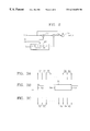
FIG. 2 is a block diagram of a video signal mixing apparatus according to the present invention;
FIGS. 3A through 3C show waveforms of signals input to the video signal mixing apparatus shown in FIG. 2;
FIG. 4 is a circuit diagram of a weighted value extractor of FIG. 2 according to a preferred embodiment of the present invention;
FIG. 5 is a flowchart illustrating a video signal mixing method according to the present invention, performed by the apparatus shown in FIG. 2; and
FIG. 6 shows a displayed image mixed by the video signal mixing apparatus according to the present invention.
DESCRIPTION OF PREFERRED EMBODIMENTS
As shown in FIG. 2, a video signal mixing apparatus according to the present invention includes a signal subtractor 22, a weighted value extractor 20, a multiplier 24 and a signal mixer 26.
The signal subtractor 22 shown in FIG. 2 subtracts a second video signal, which is input via an input port IN1 and synchronized with a clock signal CK, from a first video signal, which is input via an input port IN2 and is not synchronized with the clock signal CK, and outputs the subtracted result to the multiplier 24. Here, the first 5 and second video signals are digital signals. In the case where the second video signals is analog, the video signal mixing apparatus may include an analog-to-digital converter (not shown) for converting the analog signals into a digital signal, in accordance with clock signal CK, and outputting the converted digital signal as the second video signal to the input port IN1.
FIGS. 3A through 3C are waveforms of the digital selection signal and the clock signal for the video signal mixing apparatus. In particular, arrows of FIG. 3A represent transition direction in case the level of a digital selection signal S changes to a “high” level from a “low” level. FIG. 3B is a waveform of the clock signal CK having a period 30 and arrows of FIG. 3C represent transition direction in case the level of the digital selection signal S changes to a “low” level from a “high” level.
The weighted value extractor 20 (shown in FIG. 2) divides a period 30 of the clock signal CK, shown in FIG. 3B, into N intervals 32, 34, 36, . . . , 38 and 40 (or 42, 44 , . . . , 46,48 and 50) (where N is a natural number) and detects one of the N intervals where the digital selection signal S is changed. Here, the digital selection signal S is not synchronized with the clock signal CK. Upon detection of the change in the selection signal S, the weighted value extractor 20 outputs a predetermined value (where 0≦predetermined value≦1) allocated to the detected interval to the multiplier 24 as a weighted value K.
Here, predetermined values allocated to each interval may be linear or non-linear For example, the predetermined values applied to the intervals 32, 34, 36, . . . , 38 and 40 (or 42, 44, . . . , 46, 48 and 50), shown in FIG. 3A or 3C, may be linearly determined to be 1 N , 2 N , 3 N , , N - 1 N and N N ,
Figure US06310658-20011030-M00001
or non-linearly determined to 1 N , 2.5 N , , and N N .
Figure US06310658-20011030-M00002
Here, when determined values in a non-linear manner, the difference between the predetermined values at the intervals near the center point 54 of the cycle of the clock signal is determined to be smaller, and the difference between the predetermined values at the intervals near the start point 52 or the end point 56 of the cycle of the clock signal is determined to be larger.
The multiplier 24 multiplies the weighted value K output from the weighted value extractor 20 by the output of the signal subtractor 22, and outputs the multiplication result to the signal mixer 26. The signal mixer 26 mixes the multiplication result of the multiplier 24 with the second video signal input via the input port IN1, and outputs the mixed result to an output port OUT as a mixed video signal. Here, the mixed video signal C is expressed by the following equation (1).
C=(B−A)=(1−KA+B  (1)
where A represents the second video signal and B represents the first video signal.
As a result, the illustrative video signal mixing apparatus according to the present invention outputs only the second video signal to the output port OUT if the predetermined value is ‘0’, and only the first video signal if the predetermined value is ‘1’. However, as can be understood from the above equation (1), if the predetermined value is greater than ‘0’ and less than ‘1’, the two video signals are mixed according to the weighted value K, and the mixed video signal is output via the output port OUT.
If the digital selection signal S is generated in the interval 32 shown in FIG. 3A the predetermined value ( 1 N or 2.5 N
Figure US06310658-20011030-M00003
in the above example) allocated to the interval 32 is output as a weighted value. Thus, a mixing video signal C expressed by the following equation (2) is output via the output port OUT. C = N - 1 N × A + B N or N - 2.5 N × A + 2.5 N × B ( 2 )
Figure US06310658-20011030-M00004
FIG. 4 shows a circuit diagram of the weighted value extractor 20 shown in FIG. 2 according to a preferred embodiment of the present invention. The weighted value extractor 20 includes first through Nth buffers 60, 62, . . . , and 64, (N+1)th through (2N)th buffers 80, 82, . . . and 84, first through Nth D flip- flops 66, 68, . . . and 70, (N+1)th and (N+2)th D flip- flops 86 and 88, a phase difference detector 90, a charge pump 92 and a look-up table (LUT) 72.
The first buffer 60 of FIG. 4 outputs the digital selection signal S to the second buffer 62 after delaying by a predetermined time, and the Xth buffer, one of the second through (N−1)th buffers, outputs the output of the (X−1)th buffer to the (X+1)th buffer after delaying by a predetermined time. Here, the Nth buffer 64 outputs the output of the (N−1)th buffer to the Nth D flip-flop 70 after delaying by a predetermined time.
The output of the Yth buffer, one of the first through Nth buffers 60, 62, . . . , and 64, is output to the data input port D of the corresponding Yth D flip-flop, one of the first through Nth D flip- flops 66, 68, . . . and 70. The clock signal CK is connected to the clock port CKs of flip- flop 66, 68, and 70 and outputs Q are connected to the address port of the LUT 72. Here, the LUT 72 has prestored the predetermined values allocated to the N divided intervals, and outputs the predetermined value stored at the address as the weighted value K. The predetermined values stored in the LUT 72 may be non-linear or linear as described above.
Assuming N=8, the addresses of the LUT 72 and the predetermined values stored at the addresses can be, for example, represented by the following table 1.
TABLE 1
NON-LINEAR LINEAR
AD- PREDETERMINED VALUE PREDETERMINED VALUE
DRESS decimal binary decimal binary
00000000 −7 1001 0.000 0 000
00000001 −6 1010 0.125 0 001
or
10000000
00000011 −5 1011 0.250 0 010
or
11000000
00000111 −3 1101 0.375 0 011
or
11100000
00001111  0 0000 0.500 0 100
or
11110000
00011111 +3 0011 0.625 0 101
or
11111000
00111111 +5 0101 0.750 0 110
or
11111100
01111111 +6 0110 0.875 0 111
or
11111110
11111111 +7 0111 1.000 1 000
In table 1, the MSB of the binary representation of the linear predetermined value represents an integer and the remaining 3 bits except for the MSB represent the value below the floating point. Here, the addresses of 8 bits include none, one, two, three, four, five, six, seven and eight ‘1’s, respectively.
The (N+1)th through (2N)th buffers 80, 82, . . . and 84, the (N+1)th and (N+2)th flip- flops 86 and 88, the phase difference detector 90 and the charge pump 92 perform a function of controlling the delay time of the first through Nth buffers 60, 62, . . . , and 64 as herein described.
The (N+1)th D flip-flop 86 receives a signal EXT having frequency obtained by dividing the frequency of the clock signal CK by a predetermined number which is greater than or equal to 2, through a data input port D, and the clock signal CK through the clock port CK. The (N+2)th D flip-flop 88 receives the output Q of the (N+1)th D flip-flop 86, and the clock signal CK through the clock port CK. The signal EXT can be generated by a frequency-divider (not shown) which can be part of the weighted value extractor 20 shown in FIG. 2 or an externally connected device. The phase difference detector 90 detects the phase difference between the output Q of the (N+2)th D flip-flop 88 and the signal output from the (2N)th buffer 84, and outputs the detected phase difference to the charge pump 92. The charge pump 92 sinks or sources a charge, corresponding to the phase difference output from the phase difference detector 90, and outputs a signal having a level corresponding to the pumped charge amount to the first through (2N)th buffers 60, 62, . . . , 64 and 80, 82, . . . and 84. The delay time of the first through (2N)th buffers 60, 62, . . . , 64, and 80, 82, . . . , and 84 varies according to the level of the signal output from the charge pump 92.
Also, the (N+1)th buffer 80 outputs the output Q of the (N+1)th D flip-flop 86 to the (N+2)th buffer 82 after delaying by the predetermined time, and the Zth buffer (one of the (N+2)th through (2N−1)outputs the output of the (Z−1 )th buffer to the (Z+1 )th buffer after delaying by the predetermined time. Here, the (2N)th buffer 84 outputs the output of the (2N−1 )th buffer to the phase difference detector 90 after delaying by the predetermined time.
With the appropriate delay generated by the phase difference detector 90, charge pump 92, and buffers 60, 62-64 and 80,82 and 88, the occurrence of the selection signal S can be detected at the precise Nth interval.
As an illustration, if the above-described video signal mixing apparatus, shown in FIG. 2, is applied to a television receiver or a video cassette recorder having a function of an on-screen display (OSD), the OSD signal is input to the input port IN2 as the first video signal, and an RGB signal is input to the input port IN1 as the second video signal. A video signal mixed from the OSD signal and the RGB signal is output through the output port OUT.
Hereinafter, a video signal mixing method according to the present invention will be described with reference to the appended drawings.
FIG. 5 is a flowchart illustrating a video signal mixing method according to the present invention, which is implementable by the video signal mixing apparatus shown in FIG. 2. The video signal mixing method includes the steps 100 through 104 of calculating the weighted value for the interval where the digital selection signal S is generated. The method also includes the steps 106 through 110 of generating a mixed video signal using the weighted value and the first and second video signals.
Prior to describing the video signal mixing method with reference to FIG. 5, it is assumed that a video signal which is not synchronized with the clock signal CK is referred to as a first video signal and a video signal which is synchronized with the clock signal CK is referred to as a second video signal.
Similar to the description above for FIG. 2, a weighted value of the interval where the digital selection signal S is generated (steps 100 through 104). That is, one period of the clock signal CK is divided into N intervals in step 100. Then, a predetermined value is allocated to each of the N divided intervals in step 102. After the step 102, the interval where the digital selection signal S, which is not synchronized with the clock signal CK, occurs is detected among the N divided intervals in step 104.
After the step 104, a mixed video signal expressed by the equation (1) is generated using the weighted value and the first and second video signals in steps 106 through 110. In particular, a second video signal synchronized with the clock signal CK, is subtracted from the first video signal which is not synchronized with the clock signal CK in step 106. Then, the subtraction result and the weighted value of the interval detected in the step 106 are multiplied in step 108. After the step 108, the multiplication result and the second video signal are then mixed to generate a mixed video signal in step 110.
FIG. 6 shows a displayed image of a mixed video signal using the illustrative mixing method and mixing apparatus according to the present invention. Here, the X-axis represents pixels in the horizontal direction and the Y-axis represents horizontal lines. For example, FIG. 6 shows the part of the screen having 50 pixels×100 horizontal lines.
According to the conventional video signal mixing method, the first video signal which is not synchronized with the clock signal CK, and the second video signal synchronized with the clock signal CK, are selectively output according to the digital selection signal S, to generate a mixed video signal, as generally shown in FIG. 1. Advantageously, using the illustrative video signal mixing apparatus and method according to the present invention, the first and second video signals are mixed according to the weighted value K to generate a mixed video signal. The mixed signal is generally as shown in FIG. 6, which the dot crawling at the vertical boundary is markedly less than the dot crawling at the vertical boundary shown in FIG. 1.
The illustrative video signal mixing apparatus and method of the present invention is applicable to any video system which mixes signals as well as a television receiver or a video cassette recorder.
As described above, in the video signal mixing apparatus and the method thereof according to the present invention, a weighted value is allocated according to the point in time where the digital selection signal S which is not synchronized with the clock signal CK is generated, and two video signals, one of which is synchronized with the clock signal CK and the other of which is not synchronized with the clock signal CK, are mixed according to the weighted value K. Thus, the error causing timing jitter is reduced to 1/N, thereby minimizing dot crawling of the mixed image.
Although a preferred embodiment of the present invention has been described in detail hereinabove, it should be clearly understood that many variations and/or modifications of the basic inventive concepts herein taught which may appear to those skilled in the art will still fall within the spirit and scope of the present invention as defined in the appended claims.

Claims (19)

What is claimed is:
1. A video signal mixing apparatus for digitally mixing a first video signal which is not synchronized with a clock signal and a second video signal which is synchronized with the clock signal, in response to a digital selection signal which is not synchronized with the clock signal, and for outputting the mixed result as a mixed video signal; the apparatus comprising:
a signal subtractor for subtracting the second video signal from the first video signal;
a weighted value extractor for dividing one period of the clock signal into N intervals for detecting the interval wherein the digital selection signal is generated, and outputting a predetermined value allocated to the detected interval as a weighted value;
a multiplier for multiplying the weighted value by the output of the signal subtractor, and outputting the multiplication result; and
a signal mixer for mixing the multiplication result with the second video signal and outputting the mixed result as the mixed video signal.
2. The apparatus according to claim 1, wherein said predetermined value (k) is greater than or equal to zero and less than or equal to one.
3. The apparatus according to claim 1, wherein said predetermined value is one of a linear fraction 1 N , 2 N , 3 N , N N
Figure US06310658-20011030-M00005
and a non-linear fraction 1 N , 2.5 N N N .
Figure US06310658-20011030-M00006
4. The apparatus according to claim 1, wherein said weighted value extractor includes:
a first set of delay elements for delaying a clocked signal;
a second set of delay elements for delaying said digital selection signal, said first and second sets of delay elements having a one-to-one correspondence;
delay adjustment means for adjusting said first and second sets of corresponding delay elements by a delay amount based on a phase difference between first and and second signals, said first signal is derived from said clocked signal and said second signal is from an output of the first set of delay elements.
5. The apparatus according to claim 4, wherein outputs of said second set of delay elements are addresses of a look-up-table having pre-stored predetermined values.
6. The apparatus according to claim 1, wherein said predetermined value is one of a plurality of predetermined values stored in a look-up-table.
7. The apparatus according to claim 1, further comprising an analog-to-digital converter (ADC) for converting an analog video signal into a digital video signal in response to the clock signal, and outputting the converted digital signal as the second video signal.
8. The apparatus according to claim 1, wherein the second video signal is an RGB signal processed as a video signal, and the first video signal is an on-screen display (OSD) signal.
9. A video signal mixing method for digitally mixing a first video signal which is not synchronized with a clock signal and a second video signal which is synchronized with the clock signal, in response to a digital selection signal which is not synchronized with the clock signal, and outputting the mixed signal as a mixed video signal, the method comprising the steps of: (a) dividing one period of the clock signal into N intervals; (b) allocating N weighted values, each corresponding to a respective one of the N divided intervals; (c) detecting the interval where the digital selection signal is activated, among the N divided intervals; (d) subtracting the second video signal from the first video signal; (e) multiplying the subtraction result by the weighted value allocated to the detected interval; and (f) mixing the multiplication result with the second video signal to generate the mixed video signal.
10. The mixing method according to claim 9, wherein said weighted values are greater than or equal to zero and less than or equal to one.
11. The mixing method according to claim 9, wherein said weighted values are linear.
12. The mixing method according to claim 9, wherein said weighted values are nonlinear.
13. The method according to claim 9, wherein said step of detecting includes the steps of:
delaying a clocked signal by a first set of delay elements;
delaying said digital selection signal by a second set of delay elements, said first and second sets of delay elements having a one-to-one correspondence;
adjusting said first and second sets of corresponding delay elements by a delay amount based on a phase difference between first and second signals, said first signal is derived from said clocked signal and said second signal is from an output of the first set of delay elements.
14. The method according to claim 13, wherein outputs of said second set of delay elements form addresses of a look-up-table having pre-stored weighted values.
15. The method according to claim 9, wherein said weighted value is one of a plurality of predetermined values stored in a look-up-table.
16. An apparatus for mixing a first signal (A) which is synchronized with a clock and a second signal (B) which is not synchronized with the clock when a select signal (S) is activated, said select signal is not synchronized to the clock, the apparatus comprising:
means for generating a weighted value (K), K being dependent upon a point of time within a clock cycle of said clock at which said select signal is activated;
means for implementing (B−A) K+A to mix said first and second signals.
17. The apparatus according to claim 16, wherein K is progressively larger at the beginning or end portion of said clock cycle than the midpoint of said clock cycle.
18. The apparatus according to claim 16, further including a memory for storing a plurality of weighted values K.
19. The apparatus according to claim 18, wherein an address of said memory is formed based on a timing relationship between said select signal and said clock.
US09/140,783 1997-08-29 1998-08-27 Video signal mixing apparatus and method thereof Expired - Lifetime US6310658B1 (en)

Applications Claiming Priority (2)

Application Number Priority Date Filing Date Title
KR97-42936 1997-08-29
KR1019970042936A KR100238253B1 (en) 1997-08-29 1997-08-29 Method and apparatus for mixing video signals

Publications (1)

Publication Number Publication Date
US6310658B1 true US6310658B1 (en) 2001-10-30

Family

ID=19519492

Family Applications (1)

Application Number Title Priority Date Filing Date
US09/140,783 Expired - Lifetime US6310658B1 (en) 1997-08-29 1998-08-27 Video signal mixing apparatus and method thereof

Country Status (2)

Country Link
US (1) US6310658B1 (en)
KR (1) KR100238253B1 (en)

Families Citing this family (1)

* Cited by examiner, † Cited by third party
Publication number Priority date Publication date Assignee Title
KR100574914B1 (en) * 1999-03-23 2006-04-28 삼성전자주식회사 Video signal synthesizing apparatus and method

Citations (13)

* Cited by examiner, † Cited by third party
Publication number Priority date Publication date Assignee Title
US4126886A (en) * 1975-08-25 1978-11-21 Sanyo Electric Co., Ltd. Jitter correcting system using a pseudo composite video signal for use in a video reproduction apparatus
US4758892A (en) * 1984-04-27 1988-07-19 Ampex Corporation System for producing a video combine from multiple video images
US4851912A (en) * 1986-03-06 1989-07-25 The Grass Valley Group, Inc. Apparatus for combining video signals
US5003491A (en) * 1988-03-10 1991-03-26 The Boeing Company Multiplying video mixer system
US5027213A (en) * 1988-12-21 1991-06-25 Robert Bosch Gmbh Video signal mixer system
US5305107A (en) * 1991-04-12 1994-04-19 Alpha Image Limited Combining digital video key signals
US5353068A (en) * 1992-08-31 1994-10-04 Sony Corporation Video signal combining apparatus and method
US5428401A (en) * 1991-05-09 1995-06-27 Quantel Limited Improvements in or relating to video image keying systems and methods
US5675392A (en) * 1995-06-21 1997-10-07 Sony Corporation Mixer with common-mode noise rejection
US5825433A (en) * 1994-12-07 1998-10-20 Matsushita Electric Industrial Co., Ltd. Video mixing apparatus
US5850267A (en) * 1991-06-14 1998-12-15 Tektronix, Inc. Non-additive video mixer
US5953076A (en) * 1995-06-16 1999-09-14 Princeton Video Image, Inc. System and method of real time insertions into video using adaptive occlusion with a synthetic reference image
US6141063A (en) * 1996-09-25 2000-10-31 U.S. Philips Corporation Chroma key method and arrangement

Patent Citations (13)

* Cited by examiner, † Cited by third party
Publication number Priority date Publication date Assignee Title
US4126886A (en) * 1975-08-25 1978-11-21 Sanyo Electric Co., Ltd. Jitter correcting system using a pseudo composite video signal for use in a video reproduction apparatus
US4758892A (en) * 1984-04-27 1988-07-19 Ampex Corporation System for producing a video combine from multiple video images
US4851912A (en) * 1986-03-06 1989-07-25 The Grass Valley Group, Inc. Apparatus for combining video signals
US5003491A (en) * 1988-03-10 1991-03-26 The Boeing Company Multiplying video mixer system
US5027213A (en) * 1988-12-21 1991-06-25 Robert Bosch Gmbh Video signal mixer system
US5305107A (en) * 1991-04-12 1994-04-19 Alpha Image Limited Combining digital video key signals
US5428401A (en) * 1991-05-09 1995-06-27 Quantel Limited Improvements in or relating to video image keying systems and methods
US5850267A (en) * 1991-06-14 1998-12-15 Tektronix, Inc. Non-additive video mixer
US5353068A (en) * 1992-08-31 1994-10-04 Sony Corporation Video signal combining apparatus and method
US5825433A (en) * 1994-12-07 1998-10-20 Matsushita Electric Industrial Co., Ltd. Video mixing apparatus
US5953076A (en) * 1995-06-16 1999-09-14 Princeton Video Image, Inc. System and method of real time insertions into video using adaptive occlusion with a synthetic reference image
US5675392A (en) * 1995-06-21 1997-10-07 Sony Corporation Mixer with common-mode noise rejection
US6141063A (en) * 1996-09-25 2000-10-31 U.S. Philips Corporation Chroma key method and arrangement

Also Published As

Publication number Publication date
KR19990019548A (en) 1999-03-15
KR100238253B1 (en) 2000-01-15

Similar Documents

Publication Publication Date Title
US6310618B1 (en) Clock generation for sampling analong video
EP0166966B1 (en) Video display controller
US6664970B1 (en) Display apparatus capable of on-screen display
US7683972B2 (en) Video signal processing apparatus which generates plural clocks and performing video signal processing using the plural clocks
US4924315A (en) Video signal processing system
US6310658B1 (en) Video signal mixing apparatus and method thereof
JPH0566751A (en) Gradation correcting circuit
US6501509B1 (en) Video format converter
US6486919B1 (en) Apparatus and method for correcting jitter in a television system
KR950009698B1 (en) Line tripler of hdtv/ntsc dual receiver
KR100272168B1 (en) Digital deflection processor for crt and processing method thereof
US5142365A (en) Circuit for controlling contrast in a digital television receiver
US5241390A (en) Digital soft wipe signal generating apparatus
US7250981B2 (en) Video signal processor and video signal processing method which interpolate a video signal using an interpolation factor based on phase information of a selected clock
JP2001086364A (en) Semiconductor integrated circuit
US5552834A (en) Apparatus for displaying an image in a reduced scale by sampling out an interlace video signal uniformly in a vertical direction without sampling out successive lines
JPS6346881A (en) Digital outline correcting circuit
JP2000152030A (en) Video signal processing circuit
KR100531382B1 (en) Method of fixing sampling phase in Analog-Digital Converter and Apparatus of the same
EP1071281A1 (en) Automatic luminance adjustment device and method
US7432982B2 (en) OSD insert circuit
JP3639946B2 (en) Digital display
JP3338173B2 (en) Video signal processing device
KR0121239Y1 (en) Scanning line interpolation apparatus
JPH0544872B2 (en)

Legal Events

Date Code Title Description
AS Assignment

Owner name: SAMSUNG ELECTRONICS CO., LTD., KOREA, REPUBLIC OF

Free format text: ASSIGNMENT OF ASSIGNORS INTEREST;ASSIGNORS:KWAK, MAL SEOB;KANG, BONG SOON;REEL/FRAME:009421/0061;SIGNING DATES FROM 19980811 TO 19980817

STCF Information on status: patent grant

Free format text: PATENTED CASE

FEPP Fee payment procedure

Free format text: PAYOR NUMBER ASSIGNED (ORIGINAL EVENT CODE: ASPN); ENTITY STATUS OF PATENT OWNER: LARGE ENTITY

FPAY Fee payment

Year of fee payment: 4

FEPP Fee payment procedure

Free format text: PAYER NUMBER DE-ASSIGNED (ORIGINAL EVENT CODE: RMPN); ENTITY STATUS OF PATENT OWNER: LARGE ENTITY

Free format text: PAYOR NUMBER ASSIGNED (ORIGINAL EVENT CODE: ASPN); ENTITY STATUS OF PATENT OWNER: LARGE ENTITY

FEPP Fee payment procedure

Free format text: PAYER NUMBER DE-ASSIGNED (ORIGINAL EVENT CODE: RMPN); ENTITY STATUS OF PATENT OWNER: LARGE ENTITY

Free format text: PAYOR NUMBER ASSIGNED (ORIGINAL EVENT CODE: ASPN); ENTITY STATUS OF PATENT OWNER: LARGE ENTITY

FPAY Fee payment

Year of fee payment: 8

FPAY Fee payment

Year of fee payment: 12