US6316934B1 - System for three dimensional positioning and tracking - Google Patents
System for three dimensional positioning and tracking Download PDFInfo
- Publication number
- US6316934B1 US6316934B1 US09/345,189 US34518999A US6316934B1 US 6316934 B1 US6316934 B1 US 6316934B1 US 34518999 A US34518999 A US 34518999A US 6316934 B1 US6316934 B1 US 6316934B1
- Authority
- US
- United States
- Prior art keywords
- transmitters
- characteristic
- magnetic fields
- operative
- dimensional space
- Prior art date
- Legal status (The legal status is an assumption and is not a legal conclusion. Google has not performed a legal analysis and makes no representation as to the accuracy of the status listed.)
- Expired - Lifetime
Links
Images


Classifications
-
- G—PHYSICS
- G01—MEASURING; TESTING
- G01B—MEASURING LENGTH, THICKNESS OR SIMILAR LINEAR DIMENSIONS; MEASURING ANGLES; MEASURING AREAS; MEASURING IRREGULARITIES OF SURFACES OR CONTOURS
- G01B7/00—Measuring arrangements characterised by the use of electric or magnetic techniques
- G01B7/004—Measuring arrangements characterised by the use of electric or magnetic techniques for measuring coordinates of points
Definitions
- the present invention relates generally, to positioning systems and more particularly to positioning systems employing alternating electromagnetic fields.
- PLL technology is described in Phase locked loop: simulation and applications, by Roland E. Best, McGraw-Hill Book Company, ISBN 0070060517.
- a system comprises of N transmitters, where N ⁇ 6, and at least one probe sensor which detects at least 6 electromagnetic signals, each characterized by its own frequency.
- the probe sensor typically comprises a single magnetic field detector that is connected to a digital signal processing circuit.
- the analog output of the magnetic signal detector is a voltage signal proportional to the superposition of the N magnetic field transmitters at the coordinates x i , y i , z i , ⁇ i , ⁇ i , where the index i denote the position of the magnetic coil i.
- the antenna coils need not be exactly mutually orthogonal and certainly need not be arranged such that the centers of the antenna coils coincide.
- the analog signal is digitized and is introduced to an integrated digital signal processor block, as an input data.
- the digitized input data from the of the magnetic detector is then used by the digital signal processor unit to compute the position and orientation coordinates of the magnetic detector.
- the output from the digital signal processor unit is then transferred to the Data Communication unit and then to the System Control Unit.
- the refresh rate of the output data is typically of the order of few times per second to a few hundred times per second.
- the detector may comprise a one-axis antenna coil, as illustrated in FIG. 2, or may alternatively comprise any other suitable type of one-axis magnetic field detector, such as a Hall-effect detector or a solid state component e.g. a magneto-resistive detector or a magneto-diode or a magneto-transistor.
- the digital signal processor unit typically comprises three modules: a tracking and control module, an envelope detector module and a position determination unit.
- the tracking and control subsystem is operative to increase the precision of the position determinations by decreasing the dynamic range of the input signal to the A/D converter.
- the output of the tracking and control module is supplied to an envelope detector, which is operative to determine the received envelope amplitudes (magnitude and sign) C 1 , . . . , C N of the N magnetic signals received from the N RF transmitters.
- the tracking and control subsystem preferably comprises an Linear Predictive Coding (LPC) module.
- LPC Linear Predictive Coding
- the envelope detector module typically comprises of N identical envelope detectors (EDs) working in parallel.
- each of the ED modules comprises two sub-modules: a Phase Lock Loop (hereafter PLL), and a System Synchronization Unit, which is called during the operation of the ED module to define the absolute sign of the signal amplitude.
- PLL Phase Lock Loop
- System Synchronization Unit which is called during the operation of the ED module to define the absolute sign of the signal amplitude.
- each ED module comprises three sub-modules operating in parallel and another sub-module that is called when a system synchronization is needed.
- the three modules are: a Phase Lock Loop (hereafter PLL), a Non-coherent absolute value envelope-detector, and a Sign Detection Unit.
- PLL Phase Lock Loop
- a fourth sub-module, System synchronization unit, is then called to define the absolute sign of the signal amplitude.
- the output of the envelope detector is supplied to the position determination unit which is operative, based on the signed amplitude values supplied by the envelope detector, to provide an output indication of the position of the magnetic field detector in the sensor.
- the operation of the position determination unit is typically based on solving N analytic equations with 6 unknowns.
- a genetic algorithm method is typically employed for solving the position equation to obtain the position and orientation of the detector.
- a system for monitoring of the position of at least one portions of an object including a plurality of transmitters operative to transmit alternating magnetic fields within a three-dimensional space, and at least one positioning sensors arranged to be fixed to at least one corresponding portions of the object whose positions it is sought to monitor, each of the at least one positioning sensors including a magnetic field receiver having at least one active axes and operative to receive at least one component, lying along the at least one active axes respectively, of the alternating magnetic fields, and at least one digital signal processors for storing at least one characteristic of the magnetic fields as transmitted by the plurality of transmitters and comparing the at least one characteristic to at least one characteristic of the magnetic fields as received by at least a corresponding one of the at least one positioning sensors and, accordingly, determining and providing an output indication of at least one position characteristic of at least one corresponding portions of the object.
- the at least one sensors comprise a single sensor arranged to be fixed to a single portion of the object whose position it is sought to monitor.
- the at least one position characteristic comprises at least one dimension of the spatial position of the object portion.
- the at least one position characteristic also includes at least one dimension of the angular position of the object portion.
- the at least one sensors comprise a plurality of sensors arranged to be fixed to a corresponding plurality of portions of the object whose positions it is sought to monitor.
- the magnetic field receiver has a single (detection) active axis and is operative to receive the component of the alternating magnetic fields lying along the single (detection) active axis.
- the plurality of transmitters are operative to continuously transmit said alternating magnetic fields.
- a system for monitoring the position of at least one portions of an object in three-dimensional space having three axes including at least six magnetic transmitters each having a center and each operative to transmit alternating magnetic fields within a three-dimensional space, a transmitter orientation maintainer operative to maintain at least three of the transmitters in orientations such that at least a component of the magnetic field of at least one of the transmitters falls within each of the 3 axes of the 3-dimensional space, and wherein less than all of the centers of the transmitters coincide, at least one positioning sensors arranged to be fixed to at least one corresponding portions of the object whose positions it is sought to monitor, each of the at least one positioning sensors comprising a magnetic field receiver receiving the alternating magnetic fields from the at least six transmitters, and at least one digital signal processor for storing at least one characteristic of the magnetic fields as transmitted by the plurality of at least six transmitters and comparing the at least one characteristic to at least one characteristic of the magnetic fields as received by at least a
- the at least one digital signal processor is provided integrally with a corresponding one of the at least one positioning sensors.
- At least 3 of the transmitters are separate physical units such that the at least three transmitters can be positioned at any 3 user-selected locations.
- a system for monitoring the position of at least one portions of an object in three-dimensional space having three axes including at least six magnetic transmitters each having an active axial direction and each operative to transmit alternating magnetic fields within a three-dimensional space, a transmitter orientation maintainer operative to maintain at least three of the transmitters in orientations such that at least a component of the magnetic field of at least one of the transmitters falls within each of the 3 axes of the 3-dimensional space, and wherein less than all of the transmitters' active axial directions are mutually orthogonal, at least one positioning sensors arranged to be fixed to at least one corresponding portions of the object whose positions it is sought to monitor, each of said at least one positioning sensors comprising a magnetic field receiver receiving said alternating magnetic fields from the at least six transmitters, and at least one digital signal processor for storing at least one characteristic of the magnetic fields as transmitted by the plurality of at least six transmitters and comparing said at least one characteristic to at least one characteristic of the
- At least first and second transmitters from among the at least six transmitters transmit in different frequencies.
- At least first and second transmitters from among the at least six transmitters transmit in different phases.
- At least one of the at least one digital signal processors is operative to simultaneously process magnetic field characteristics arriving from more than one of the at least six transmitters.
- the RF trigger provides a timing signal to at least one of the at least one sensors.
- at least one of the sensors computes the absolute phase of the at least six transmitters, based on said timing signal.
- a method for monitoring of the position of at least one portions of an object including affixing at least one positioning sensors to at least one corresponding portions of the object whose positions it is sought to monitor, the sensors being operative to receive alternating magnetic fields existing within a three dimensional space containing the object, comparing at least one characteristic of the magnetic fields as transmitted to at least one characteristic of the magnetic fields as received by the sensors, and using a result of the comparing step as an input to a genetic natural selection process for determining and providing an output indication of at least one position characteristic of at least one corresponding portions of the object.
- At least one of the sensors comprises a Linear Predicted Coding control loop operative to increase the dynamic range of incoming signals.
- at least one of the sensors comprises a solid-state component.
- at least one of the sensors comprises a control loop to improve the dynamic range of the signal intensity without the use of electronic components common in the art.
- At least one of the sensors comprises a PLL configuration whose output is relatively insensitive to its input amplitude.
- At least one dynamic property of the PLL apparatus does not substantially depend on the input amplitude of the PLL apparatus.
- the bandwidth of the PLL apparatus does not substantially depend on the input amplitude of the PLL apparatus.
- the relaxation time constant of the PLL apparatus does not substantially depend on the input amplitude of the PLL apparatus.
- the dynamic properties of the PLL, specifically bandwidth, and its relaxation time constant typically do not depend on the input amplitude.
- a method for monitoring of the position of at least one portions of an object including positioning a plurality of transmitters operative to transmit alternating magnetic fields within a three-dimensional space and affixing at least one positioning sensors arranged to be fixed to at least one corresponding portions of the object whose positions it is sought to monitor, each of the at least one positioning sensors comprising a magnetic field receiver having at least one active axes and operative to receive at least one component, lying along the at least one active axes respectively, of the alternating magnetic fields and storing at least one characteristic of the magnetic fields as transmitted by the plurality of transmitters and comparing the at least one characteristic to at least one characteristic of the magnetic fields as received by at least a corresponding one of the at least one positioning sensors and, accordingly, determining and providing an output indication of at least one position characteristic of at least one corresponding portions of the object, wherein the storing, comparing, determining and providing step is performed locally rather than remotely.
- a method for monitoring the position of at least one portions of an object in three-dimensional space having three axes including positioning at least six magnetic transmitters each having a center and each operative to transmit alternating magnetic fields within a three-dimensional space, including maintaining at least three of the transmitters in orientations such that at least a component of the magnetic field of at least one of the transmitters falls within each of the 3 axes of the 3-dimensional space, and wherein less than all of the centers of the transmitters coincide, affixing at least one positioning sensor to at least one corresponding portions of the object whose positions it is sought to monitor, each of the at least one positioning sensors comprising a magnetic field receiver receiving said alternating magnetic fields from the at least six transmitters, and storing at least one characteristic of the magnetic fields as transmitted by the plurality of at least six transmitters and comparing the at least one characteristic to at least one characteristic of the magnetic fields as received by at least a corresponding one of the at least one positioning sensors and, accordingly,
- a method for monitoring the position of at least one portions of an object in three-dimensional space having three axes including positioning at least six magnetic transmitters each having an active axial direction and each operative to transmit alternating magnetic fields within a three-dimensional space, including maintaining at least three of the transmitters in orientations such that at least a component of the magnetic field of at least one of the transmitters falls within each of the 3 axes of the 3-dimensional space, and wherein less than all of the transmitters' active axial directions are mutually orthogonal, affixing at least one positioning sensors arranged to be fixed to at least one corresponding portions of the object whose positions it is sought to monitor, each of said at least one positioning sensors comprising a magnetic field receiver receiving the alternating magnetic fields from the at least six transmitters, and storing at least one characteristic of the magnetic fields as transmitted by the plurality of at least six transmitters and comparing said at least one characteristic to at least one characteristic of the magnetic fields as received by at least a corresponding
- FIG. 1 a is a simplified pictorial illustration of a positioning system constructed and operative in accordance with a preferred embodiment of the present invention which outputs the position of an object as a whole or parts thereof, such as, in the illustrated embodiment, body parts of a human user;
- FIG. 1 b is a virtual reality application of the system of FIG. 1 a in which a simulation system receives the position outputs generated by the system of FIG. 1 a and generates a display image including a computer-generated scene and a figure having body part motion which mimics the body part motion of the human user of FIG. 1 a as detected by the positioning system of FIG. 1 a;
- FIG. 1 c is a detailed diagrammatic illustration of an RF transmitter and a positioning sensor provided in accordance with a preferred embodiment of the present invention
- FIG. 1 d is a simplified functional block diagram illustration of the apparatus of FIG. 1 a;
- FIG. 2 is a simplified block diagram illustration of a first preferred embodiment of an individual one of the positioning sensors of FIG. 1;
- FIG. 3 is a simplified block diagram illustration of a first preferred digital signal processing unit useful in the sensor of FIG. 2;
- FIG. 4 is a simplified block diagram illustration of the tracking and control subsystem of FIG. 3, constructed and operative in accordance with a preferred embodiment of the present invention
- FIG. 5 is a simplified block diagram illustration of the envelope detector of FIG. 3, constructed and operative in accordance with a preferred embodiment of the present invention
- FIG. 6 a is a simplified block diagram illustration of one of the envelope detecting (ED) modules of FIG. 5, constructed and operative in accordance with a preferred embodiment of the present invention
- FIG. 6 b is a simplified block diagram illustration of a PLL sub-module forming part of the apparatus of FIG. 6 a and FIG. 6 c;
- FIG. 6 c is simplified block diagram of an alternative configuration of one of the ED's
- FIG. 6 d is a simplified block diagram illustration of an envelope detector sub-module forming part of the apparatus of FIG. 6 c;
- FIG. 7 a is a simplified flowchart illustration of a preferred method of operation for the position finding subsystem of FIG. 3, based on a genetic process for obtaining the final position and orientation of an object of interest;
- FIG. 7 b is a simplified flowchart illustration of a preferred method for performing the coordinate possibility evaluation step of FIG. 7 a;
- FIG. 7 c is a simplified flowchart illustration of a preferred method for performing the new generation creation step of FIG. 7 a;
- FIG. 8 is a simplified block diagram illustrations of a second preferred embodiment of an individual one of the positioning sensors of FIGS. 1 a-c ;
- FIG. 9 is a simplified block diagram illustration of a preferred digital signal processing unit useful in the sensor of FIG. 9;
- Appendix A is a computer code listing of a preferred software implementation of the digital signal processing unit of FIG. 8 .
- spatial position is employed herein to refer to the location of a detector or other object within a three-dimensional space which may, for example, be expressed in Cartesian coordinates (x, y, z) or alternatively may be expressed in any other suitable coordinate system such as a polar system.
- angular position is employed herein to refer to an orientation of the detector or other object relative to the three-dimensional space which may, for example, be expressed as ( ⁇ , ⁇ ) where the designation of ⁇ must also include the quadrant in which the angle ⁇ is located.
- the orientation may, of course, also be expressed in other suitable coordinates such as Euler coordinates or such as yaw, pitch and roll.
- RF transmitter is employed herein to refer to a transmitter transmitting at a frequency of 5 KHz and upwards and preferably at a frequency of 10-100 KHz.
- the transmissions are pulse transmissions.
- the transmission are continuous rather than pulse transmissions.
- electromagnetic field is intended to include electromagnetic fields as well as magnetic fields.
- the analog signal is digitized and is introduced to an integrated digital signal processor block 62 , as an input data.
- the digitized input data from the magnetic detector 50 is then used by the digital signal processor unit 62 to calculate the position and orientation coordinates of the magnetic detector 50 .
- the output from the digital signal processor unit 62 is then transferred to the Data Communication unit 51 and then to the System Control Unit 30 .
- the refresh rate of the output data is of the order of few times per second to a few hundred times per second.
- Detector 50 may comprise a one-axis antenna coil, as illustrated in FIG. 2, or may alternatively comprise any other suitable type of one-axis magnetic field detector, such as a Hall-effect detector or a solid state component e.g. a magneto-resistive detector or a magneto-diode or a magneto-transistor.
- the digital signal processor unit 62 comprises three modules: a tracking and control module 110 , an envelop detector module 114 and a position determination unit 116 (FIG. 3 ).
- the tracking and control subsystem 110 is operative to increase the precision of the position determinations by decreasing the dynamic range of the input signal to the A/D converter.
- the output of block 110 is supplied to an envelope detector 114 , which is operative to determine the received envelope amplitudes (magnitude and sign) C 1 , . . . , C N of the N magnetic signals received from the N RF transmitters.
- the tracking and control subsystem 110 of FIG. 4 preferably comprises a Linear Predictive Coding (LPC) module.
- Block 114 is described schematically in FIG. 5 . and comprises of N identical envelope detectors (ED's) working in parallel.
- ED's envelope detectors
- One of the ED's is described schematically in two variations. The first configuration is shown in FIG. 6 a, where each of the ED modules comprises two sub-modules: a Phase Lock Loop (hereafter PLL) 132 , described in detail below with reference to FIG.
- PLL Phase Lock Loop
- each ED module comprises three sub-modules operating in parallel and another sub-module that is called when a system synchronization is needed (see below).
- the three modules are: a Phase Lock Loop 132 (hereafter PLL), a Non-coherent absolute value envelope-detector 133 , and a Sign Detection Unit 415 .
- PLL Phase Lock Loop
- the fourth sub-module, a System synchronization unit 420 is then called to define the absolute sign of the signal amplitude.
- the output of the envelope detector 114 is supplied to the position determination unit 116 .
- Unit 116 is operative, based on the signed amplitude values supplied by unit 114 , to provide an output indication of the position of the magnetic field detector 50 in sensor 40 .
- the position determination of module 116 is based on solving N analytic equations with 6 unknowns.
- a genetic algorithm method is implied for solving the position equation to obtain the position and orientation of the detector 50 , described in detail below with reference to FIGS. 7 and 8.
- FIG. 1 a is a simplified pictorial illustration of a positioning system constructed and operative in accordance with a preferred embodiment of the present invention.
- the system of FIG. 1 a preferably outputs the spatial and/or angular position of an object, such as a human user, as a whole or of parts thereof, such as, in the illustrated embodiment, body parts of the human user.
- Each transmitter defines an active axial direction, e.g. the axis of the coil if the transmitter comprises a coil.
- the six (in the illustrated embodiment) antenna coils each transmit at a different frequency f 1 , . . . , f 6 respectively and each produce a magnetic field.
- the coils are preferably arranged such that, for each of the three orthogonal axes, there exists at least two antenna coils whose magnetic fields each have a component substantially along that orthogonal axis.
- the coils may be mutually arranged such that there are two triplets of antenna coils and each triplet of antenna coils includes, for each of the three orthogonal axes, at least one antenna coil whose magnetic field has a component along that orthogonal axis.
- the number of antenna coils is assumed to be 6, however, it is appreciated that any suitable number N of antenna coils in excess of 6 may be employed, particularly for redundancy purposes.
- the antenna coils need not be exactly mutually orthogonal and certainly need not be arranged such that the centers of the antenna coils coincide. This is advantageous because it allows greater flexibility in positioning the antenna coils in the range in which the object is known to move, such that the antenna coils are well distributed such that the object can be accurately and rapidly positioned in all portions of the range. Also, this tends to cut down production costs because it is not necessary to precision-position the coils in a mutually orthogonal configuration.
- each of the at least six RF transmitters 10 , 12 , 14 , 16 , 18 and 20 comprises an oscillator which provides a sinusoidal signal output.
- the signal outputs from the signal sources are in the range of 10-100 KHz.
- a positioning sensor 40 is provided for sensing the spatial and/or angular position of a magnetic field detector ( 50 in FIG. 2) included therein.
- the positioning sensor also, of course, senses the spatial and/or angular position of any objects which are fixed with respect to the magnetic field detector 50 of FIG. 2 .
- the spatial and/or angular position is typically computed relative to a predetermined reference coordinate system.
- a preferred implementation of sensor 40 is described in detail below with reference to FIG. 2 .
- positioning sensor 40 employs a single magnetic detector ( 50 in FIG. 2) which outputs to an on-board digital signal processor circuit ( 62 in FIG. 2 ), which, in turn, provides an output indication of the spatial and angular positions of detector 50 , each in three dimensions.
- the detector 50 may comprise a multi-axis magnetic detector.
- the detector 50 may comprise a one-axis antenna coil, as illustrated in FIG. 2, or may alternatively comprise any other suitable type of one-axis magnetic field detector, such as a Hall-effect detector or a solid state component e.g. a magneto-resistive detector or a magneto-diode or a magneto-transistor.
- the sensor 40 is attached to a moving object or individual 30 , such as a person, whereas the RF transmitters are stationary. If the moving object or person 30 is not rigid, there may be a plurality of sensors 40 and each of these is attached to a corresponding one of a plurality of portions of the moving object or individual, as shown in FIG. 1 a. This allows monitoring of the spatial and angular positions of these individual portions.
- moving object is intended to refer to an object of interest which is moving at least a part of the time or which has at least one part which is moving at least a part of the time.
- the “moving object” may not itself be in motion but its position relative to another object which is sometimes in motion, is of interest.
- moving object is intended to refer to any object whose absolute or relative location is of interest to a user.
- the RF transmitters may be fairly close together, e.g. even less than one meter apart however, most advantageously, they are as far apart as is feasible, depending on the application.
- FIG. 1 b is a display image generated by a virtual reality application of the system of FIG. 1 a .
- a virtual reality system receives the position outputs generated by the system of FIG. 1 a and generates the display image of FIG. 1 b which includes a computer-generated scene (fence, path and trees in the illustrated embodiment) and a figure having body part motion which mimics the body part motion of the human user of FIG. 1 a as detected by the positioning system of FIG. 1 a.
- FIG. 1 c is a detailed diagrammatic illustration of one of the N RF transmitters of FIG. 1 a ., such as RF transmitter 12 , and one of the detection coil 50 of the positioning sensors 40 provided in accordance with a preferred embodiment of the present invention.
- the magnetic field at the point g at the center of the magnetic detector 50 due to a current flowing in a thin conducting circular loop representing the source i is well known in the literature and may be expressed in terms of Elliptic integrals of the first and second kind as described in J. D. Jackson, Classical Electrodynamics, Wiley, Second Ed., 1975, Chapter 5, p. 178. Since working with such integrals is cumbersome, it is alternatively possible to use approximate expressions as described herein.
- the magnetic field may thus be written as:
- I i (t) the current in the loop i, all the currents in the system are assumed harmonically time dependent;
- a i the i th source coil area.
- T i the number of turns in the ith source coil
- I i the current in the ith source coil
- Equation 1 when the quotient is greater than 0.05, the expected error of the above approximation is of the order 10 ⁇ 4 .
- is not always fulfilled, especially in cases where the transmitters are distributed throughout the entire volume of the object's range, in order to improve system performance. In these cases, the second term in Equation 1 becomes significant.
- the transmitter coil is driven by a time harmonic dependent current, and thus:
- a d Is the detector's coil area.
- T d Is the number of turns in the detector coil
- V i C i ⁇ i (15)
- ⁇ i ⁇ 0 ⁇ A i ⁇ T i ⁇ I i ⁇ ⁇ i ⁇ ⁇ ⁇ ( ⁇ i ) 4 ⁇ ⁇ ( 17 )
- ⁇ is the transfer function of the coil and its front-end electric circuit up to the point Y(t) in FIG. 2 or FIG. 8 .
- the 6 sources allow the 5 coordinates (x, y, z, ⁇ , ⁇ ) of spatial and angular position to be derived, plus a sign which removes the ambiguity of the direction of the normal vector from the sensor coil.
- the magnetic field transmitters block 34 comprises of N transmitters, where N ⁇ 6. These transmitters radiate simultaneously at N different frequencies.
- the amplitude and phase of each of the N transmitters is controlled by the system control block 30 .
- the magnetic field is detected by a magnetic field detector block 50 .
- the output of the magnetic signal detector 50 is a voltage signal proportional to the superposition of the N magnetic field transmitters at the coordinates x i , y i , z i , ⁇ i , ⁇ i .
- This signal is introduced to the signal conditioner block and A/D converter block 64 , which amplifies and filters the input signal to a proper bandwidth around the system working frequencies.
- the signal is then digitized by the Analog to Digital (A/D) converter and is transferred to the Digital Signal Processor (referred to as DSP hereafter) block 62 as an input data.
- DSP Digital Signal Processor
- Another input data introduced to the DSP is the synchronization signal through the communication module 51 which receives the synchronization data from the system control 30 by the use of a wire line or wireless.
- the synchronization signal determines the signals polarity at the detector 50 relative to the magnetic transmitters as described below.
- the synchronization input to the DSP block is updated at a very slow rate compared to the magnetic detector input, as described below.
- the digitized input data from the of the magnetic detector 50 is then used by the digital signal processor unit 62 to calculate the position and orientation coordinates of the magnetic detector 50 .
- the output from the digital signal processor unit 62 is then transferred to the Data Communication unit 51 and then to the System Control Unit 30 .
- the refresh rate of the output data is of the order of few times per second to a few hundred times
- the position data may then be transferred to the system control unit via wireline or wireless data communication procedure that may optionally display or further process the positioning information of sensor 40 .
- the system control unit also controls the amplitudes and phases of the N magnetic transmitters in the system.
- the system control unit 30 in FIG. 1 d may be composed of a separate unit block 32 to collect spatial position data from all sensors 40 to be displayed or to be used by an external application unit. Alternatively, the positioning information from one or all sensors may directly be received by an external application unit.
- FIG. 2 is a simplified block diagram illustration of a preferred implementation of an individual one of the positioning sensors 40 of FIG. 1 a.
- a magnetic field detector 50 such as, in the illustrated embodiment, a coil
- BPF bandpass filter
- PGA programmable gain amplifier
- the two inputs to the differential amplifier 56 are Y(t) and HX P (t) which is the best prediction to the signal Y at the time t.
- the analog signal is passed through a low pass filter 58 which removes disturbances and noise above the working frequencies.
- This signal is digitized by an A/D converter 60 and introduced to digital signal processing circuitry 62 .
- Digital signal processing circuitry 62 whose operational modes will be described below in detail, provides a gain-control output to differential amplifier 56 and also provides a feedback output via a digital-to-analog converter 66 , and preferably via an amplifier 68 and a low pass filter 70 , to a feedback input of differential amplifier 56 .
- the feedback output of the DSP unit 62 which is the best discrete prediction of Y(t), is termed herein HX P j .
- FIG. 3 is a simplified block diagram illustration of a preferred implementation of the digital signal processing unit 62 in the sensor illustrated in FIG. 2 .
- the apparatus of FIG. 3 includes a tracking and control subsystem 110 which is omitted in another implementation of DSP unit 62 (FIG. 9 ).
- the tracking and control subsystem 110 is a participant in a feedback loop shown in FIG. 2 and comprises unit 110 as well as units 66 , 68 and 70 . These units are operative to limit the dynamic range of the input signal Y(t) to A/D unit 60 , which is advantageous because A/D unit 60 may then comprise a common and relatively low cost unit such as a 16 bit A/D converter.
- the tracking and control subsystem of FIG. 3 and the feedback loop of FIG. 2 may be omitted, as shown in FIGS. 8 and 9 respectively.
- the A/D unit 60 typically comprises a relatively high cost, high resolution unit such as a 20-24 bit A/D converter to get the same performances as with the tracking and control subsystem and the feedback loop.
- the apparatus of FIG. 3 includes a tracking and control subsystem 110 which, for the reasons described above, is operative to increase the precision of the spatial and angular position determinations by sampling the output of sensor 40 .
- tracking and control subsystem 110 receives a digital input from A/D converter 60 (FIG. 2 ).
- Tracking and control subsystem 110 provides a digital output to the D/A converter 66 (FIG. 2 ).
- the functionality of tracking and control subsystem 110 is to manage a feedback loop which also includes amplifier 68 , low pass filter 70 , differential amplifier 56 , and AID converter 60 , such that the A/D converter 60 operates on a relatively small dynamic range signal which is provided thereto by differential amplifier 56 .
- the tracking and control subsystem 110 may for example comprise a Kalman filter such as the filter illustrated in FIG. 4 .
- any suitable curve-fitting method such as cubic or higher order interpolation based on a suitable metric such as least squares, may be used to fit a curve to the output samples generated by A/D 60 . Thereby the input signal Y(t) to the differential amplifier 56 is approximated to an acceptable degree.
- the output of block 110 is a full dynamic range signal, which may have a dynamic range which is three orders of magnitude greater than that of the signal which passes through A/D converter 60 .
- the output of block 110 is supplied to an envelope detector 114 , which is operative to determine the received envelope amplitudes (magnitude and sign) C 1 , . . . , C 6 of at least six magnetic carrier signals received from the six transmitter coils 10 , 12 , 14 , 16 , 18 and 20 respectively.
- an envelope detector 114 which is operative to determine the received envelope amplitudes (magnitude and sign) C 1 , . . . , C 6 of at least six magnetic carrier signals received from the six transmitter coils 10 , 12 , 14 , 16 , 18 and 20 respectively.
- the output of the envelope detector 114 is supplied to the position determination unit 116 .
- Unit 116 is operative, based on the signal amplitude values supplied by unit 114 , to provide an output indication of the spatial and/or angular position of the magnetic field detector 50 in sensor 40 (FIG. 1 ).
- a preferred method of operation for the position determination unit 116 based on a genetic process for obtaining the final position and orientation of the object of interest, is described below with reference to FIGS. 7 a - 7 c.
- FIG. 4 is a simplified block diagram illustration of the tracking and control subsystem of FIG. 3, constructed and operative in accordance with a preferred embodiment of the present invention.
- the tracking and control subsystem 110 of FIG. 4 preferably comprises an linear predictive Coding module (LPC) as described for example in Digital Coding of Waveforms by Jayant N. S., Englewood Cliffs, N.J.; Prentice Hall, 1984.
- LPC linear predictive Coding module
- the LPC module of FIG. 4 typically comprises several units interconnected as shown to generate an output signal comprising a best prediction to the input signal Y j where the index j is a sample index.
- the K block 120 may comprises a conventional Kalman gain unit or more generally any filter gain unit.
- the G unit 126 comprises a one step transition matrix.
- the D unit 128 provides a delay for synchronization between the input and the prediction vector.
- the H unit 124 comprises a coefficients matrix for selection of the prediction signal from the prediction vector.
- the quantity X P is a vector of prediction for Y.
- the parameter X c is a vector of correction for X p and is obtained by computing a correction of the vector X c j given X j P .
- the input Y J d to the LPC module of FIG. 4, as shown, is the difference between the predicted signal X j P (the prediction of X J given X j ⁇ 1 ) and the input signal Y j , i.e.:
- the tracking and control system of FIG. 4 has two outputs, as shown, to the D/A unit 66 and to the envelope detector 114 .
- the output to the envelope detector 114 is the best estimation to Y j .
- FIG. 5 is a simplified block diagram illustration of the envelope detector 114 of FIG. 3, constructed and operative in accordance with a preferred embodiment of the present invention.
- ED envelope detecting
- FIG. 6 a is a simplified block diagram illustration of the i'th envelope detecting (ED) module 130 of FIG. 5, constructed and operative accordance with a preferred embodiment of the present invention.
- ED envelope detecting
- phase is denoted by the letter “p”, rather than the more conventional ⁇ , in order to prevent confusion between the letter ⁇ which, in the present specification, is used to denote one of the two angular position coordinates.
- the i'th envelope detector module (ED) 130 is operative to extract the strength of the electromagnetic interaction between the detector 50 and the i'th transmitter, from the electromagnetic signal received by the detector 50 .
- the input to the i'th ED module 130 is a time series Y(t j ).
- This series is a superposition of the N sinusoidal waves, each amplitude modulated according to the relative position between the detector 50 and the i'th transmitter.
- the output of the i'th ED module 130 is time-series of the i'th signed envelope C i (t k ).
- the envelope detection is similar for all N transmitters. Therefore, only the detection of a single envelope is described below.
- the process is performed N times, i.e. once per transmitter, preferably in parallel, by N ED modules 130 respectively.
- Each ED module typically comprises two sub-modules. These modules are: a Phase Lock Loop (hereafter PLL) 132 , described in detail below with reference to FIG. 6 b and a System synchronization unit 420 , is then called to define the absolute sign of the signal amplitude.
- PLL Phase Lock Loop
- FIG. 6 b is a simplified block diagram illustration of the PLL sub-module 132 forming part of the apparatus of FIG. 6 a.
- the Phase-locked loop (PLL) unit of FIG. 6 b is a control system that follows the phase and frequency of its input. Given the angular velocity ⁇ i of a sinusoidal waveform contained in its input signal, the PLL follows its phase and compensates for small frequency fluctuations.
- PLL Phase-locked loop
- One such configuration useful for implementing the PLL unit of FIG. 6 b is the Tanlock PLL, described in Phase locked and Frequency Feedback Systems: Principles and Techniques, J. Klapper and J. T. Frankle, Chapter 8, p. 256, Academic Press, New York, 1972.
- the Tanlock configuration as shown in FIG. 6 b, uses both I and Q branches to close the phase loop.
- ⁇ circumflex over ( ⁇ ) ⁇ j i and ⁇ circumflex over (P) ⁇ i j are the estimated values in the PLL procedure, of frequency ⁇ i and the phase P i at the time t j .
- Initially ⁇ circumflex over (P) ⁇ i j is zero and ⁇ circumflex over ( ⁇ ) ⁇ i is set to the nominal frequency of the i'th carrier.
- Low pass filters 150 and 190 filter the results of the multiplication by 170 and 210 respectively.
- ⁇ circumflex over ( ⁇ ) ⁇ i ⁇ i and after the proper filtering process, only the envelope remains, i.e. the slowly changing component of the i'th input.
- the envelope of the Q channel after multiplying by 2 is given by:
- phase error ⁇ p i (t j ) is used by the PLL to update its own frequency.
- a Proportional—Integral (PI) controller 320 also termed herein a “loop filter”, is used to compute a correction to the frequency.
- the transfer function F(s) characterizing the PI controller is defined by:
- K and K 1 are constants of the control loop filter 320 , and are set such that the closed loop bandwidth is approximately 1 Hz and the damping factor is approximately in the range of 0.7-1.0.
- the PLL configuration of FIG. 6 b has several advantages over other implementation possibilities in the art:
- the System synchronization Sub-module 420 is now described.
- the extraction of signed amplitude is possible if the initial phase of the carrier is known. Otherwise, the system never knows if it is locked to the carrier or it is out of phase to it. Therefore, an auxiliary synchronization mechanism 420 is provided.
- the ED 130 of FIG. 6 a receives an auxiliary signal SYS i composing a time series of ones and zeros.
- This synchronization signal (SYS i ) is one when the carrier is positive, and zero otherwise.
- SYS i arrives, the output of 210 of FIG. 6 a , i.e.
- the PLL's estimated sine wave is cross-correlates it with Y(t j ) over a time period of approximately 100 msecs. If Y(t j ) appears to be in anti-correlation with SYS i then Y(t j ) is multiplied by ⁇ 1.
- FIG. 6 c Another ED configuration shown in FIG. 6 c.
- This configuration has an advantage over the previous configuration due to its ability to determine sine envelope C i (t k ) to the next stage without dependency on the loop ‘locking’.
- This configuration comprises three sub-modules operating in parallel and another sub-module operative rarely.
- the three sub-modules are: a Phase Lock Loop (hereafter PLL) 132 , a Non-coherent absolute envelope-detector 133 , described in detail below with reference to FIG. 6 d and a Sign Detection Unit 415 .
- the fourth sub-module a System synchronization unit 420 .
- the PLL sub-module 132 and the System synchronization 420 are identical in both configurations and were described above.
- the Non-coherent absolute envelope-detector sub-module 133 and the Sign Detection Unit 415 are described hereinbelow.
- the Sign detection Sub-module 415 shown in FIG. 6 c In the alternative configuration the Sign detection Sub-module is needed because this sub-module has to be operative even when the PLL unlocked. When the i'th transmitter changes sign the effect is of changing the sign of the carrier signal. When the PLL is unlocked, a sign change of the carrier does not change the sign of phase estimated by the PLL ⁇ circumflex over (P) ⁇ i j . In this configuration the two branches of the PLL has a symmetry of 180° and not 360°. To follow and correct the phase change of the carrier signal module 415 uses a 360° phase detector which has a symmetry of 360°.
- the auxiliary signal is cross correlated with the output of sub-module 400 which contains the proper phase of the ED module 130 .
- FIG. 6 d is a simplified block diagram illustration of a non-coherent absolute value envelope detector sub-module 133 forming part of the apparatus of FIG. 6 a .
- the amplitude of the corrected voltage signal, at the relevant frequency, as synthesized by the raw detected signal as defined above, is given by:
- LPC as defined by equation 24 is the output of block 150 in FIG. 6 d , similarly
- LPS as defined by equation 26 and is the output of block 150 in FIG. 6 d.
- FIGS. 6 a - 6 d are only two possible implementations of envelope detector 114 of FIG. 3 .
- the envelope detector 114 may, for example, be based on Fourier transforms.
- FIG. 7 a illustrates one suitable method of operation for position determination unit 116 , based on an iterative Genetic process for obtaining the final position and orientation of an object of interest.
- the output indication typically includes spatial and angular position information, e.g. three position coordinates, typically Cartesian coordinates x, y, z; plus angular position information such as ( ⁇ and ⁇ including its quadrant).
- the method of FIG. 7 a is based on solving N analytic equations with 6 unknowns (step 835 , is described in detail with reference to FIG. 7 b ).
- N there are more than 6 equations in 6 unknowns. This redundancy may be used to increase accuracy of the system, preferably by applying an averaging process to the measured amplitudes, of the signals at their different frequencies, representing the magnetic field parameters.
- step 800 N amplitude values are received from unit 114 .
- an initial position box is defined for the magnetic detector 50 .
- the definition of the initial position box typically depends on the mode of operation of the positioning system which is typically selected from two possible modes: an initial positioning/reset mode and a tracking mode.
- the initial positioning/reset mode is intended for situations in which there is no knowledge available, or insufficient reliable knowledge available, regarding the prior position of the detector 50 . If the system is operating in this mode, the initial position box is simply the entire area in which the system is operative.
- step 810 uses available knowledge regarding the maximum velocity of the moving object or individual 30 to which sensor 40 is attached, in order to define an initial position box within which the detector 50 must be after a predetermined period of time.
- an initial population of coordinate possibilities is defined, i.e. a suitable number of sets of possible values for each of the components of the output (3 spatial coordinates and 3 angular coordinates, typically ⁇ and ⁇ including its quadrant).
- the initial population is generated by randomly selecting sets of possible values within the initial position box.
- the initial population may be generated by selecting a predetermined number of possible values which are suitably dispersed, e.g. uniformly dispersed, within the initial position box.
- step 835 the fit of each individual coordinate possibility is computed, as described in detail below with reference to FIG. 7 b.
- the Fitness is compared to a predetermined threshold value hereafter called “Tolerance”.
- the threshold value is selected in accordance with the positioning resolution which is required for a particular application. For example, if it is desired to position the object with a resolution of 3 mm and 0.5 degrees, the threshold value for Tolerance is typically 10 ⁇ 5 .
- the threshold value for Tolerance is typically 10 ⁇ 5 .
- none of the coordinate possibilities in the initial population pass the threshold value. If none of the members of the current population pass the threshold, then step 870 is performed and the method then returns to step 880 .
- step 880 If at least one member of the current population pass the threshold, then that member is announced (step 880 ) as the best solution, i.e. as the position of the sensor 40 . If more than one member passes the threshold, the member having the smallest Fitness value is announced as the best solution.
- a new generation is formed.
- the new generation is typically formed by generating a subset of the current population and applying mutations, crossovers and reproductions (duplications) to that subset or new population.
- the subset of the current population typically includes a predetermined number of population members (coordinate possibilities) having the lowest Fitness values. The larger the subset, the less iterations are required to obtain a solution.
- the new population is simply the 10 members of the initial population having the lowest Fitness values.
- FIG. 7 b is a simplified flowchart illustration of a preferred method for implementing step 835 for an individual coordinate possibility 1 .
- each member of the population (each sextuplet (x, y, z, ⁇ , ⁇ ) including quadrant) is plugged into each of the N ⁇ 6 equations in the equation system of step 900 , generating L systems of N equations.
- the N expressions on the left side of the N equations, respectively, are not equal to zero (unless the sextuplet is in fact a solution of the equation).
- the absolute value of the result of plugging in the sextuplet into each of the six expressions is termed the “partial fitness” (hereafter Fit i ) of that equation for that sextuplet.
- step 910 the N ⁇ 6 values of each of the Fit i calculated for each coordinate possibility 1 in the initial L-sized population are combined into a single value.
- Fit i are combined by computing the sum of squares of the N values of each of the Fit i parameters calculated for each coordinate possibility 1 in the initial population. This sum of squares is termed herein the “Fitness 1 ” of an individual coordinate possibility 1.
- FIG. 7 c is a simplified flowchart illustration of a preferred method for performing step 870 of FIG. 7 a.
- the method of FIG. 7 c uses genetic processes such as mutation, crossover and duplication on a pre-selected group of members in the present generation in order to generate a “new generation” which better fits the required optimal solution to the problem.
- the starting point (step 950 ) is a generation number m that includes L members, for instance, 100 members (i.e. points, where each point includes a spatial triplet of x, y and z and orientation angles ⁇ and ⁇ ).
- the size L of the total population in each generation can be set by the user (or automatically by the system) according to some pre-defined criterions as described herein below.
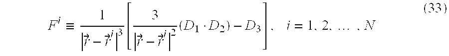
- the Fit i is defined according to:
- step 900 where Ci and Fi are as referred also in FIG. 7 b , step 900 .
- N sys is the system noise, defined as the lowest level of signal that is detected by the detector 50 as a valid, i.e. non-noise signal in Volts [V].
- Tolerance is a value, expressed in volts, which is selected to provide a required accuracy of computation. Empirically, the value of Tolerance is approximately 10 ⁇ 5 V if the accuracy of positioning required is approximately 10 ⁇ 3 meters.
- the Fitness is found for all members of generation m.
- Fitness is defined as the criterion for how “good” is a specific point, as a potential solution to the problem, when compared to all other points (the lower Fitness, the better).
- step 970 the method finds the v members with the lowest fitness measure (the selected subgroup).
- step 980 the method duplicates the “best” member of the m'th generation (typically the member with the lowest Fitness) to obtain s percent, for instance 10%, of the (m+1)'th generation.
- a preferred definition for r 1 is as follows:
- r 1 max(delta_range — x , delta_range — y , delta_range — z )/B 1 (36)
- B 1 may, for example be 10.
- B is an expression of the degree of confidence which it is desired to ascribe to the members of the current population. The smaller the value of B, the closer the members of the next generation tend to be to the members of the present generation.
- delta_range_x, delta_range_y, delta_range_z are the dimensions of the range in which the object whose position is being measured is assumed to reside. For example, if the object is known to reside within an area whose x-dimension ranges from 4 length units to 9 length units then delta_range_x is 5.
- Mutation level II In step 1000, a radius r 2 is defined and the method randomly chooses new v percents, for instance 20%, of the m+1 generation, in the vicinity of each of the “best” w members, for instance 10 members of the selected subgroup.
- r 2 is defined as follows:
- B 2 ⁇ B 1 and may, for example, be 20.
- only one level of mutation may be employed.
- 40% of the members of the m+1 generation may be selected in an r 1 vicinity of the members of the selected subgroup of generation m.
- more than two levels of mutation may be employed.
- step 1010 the method randomly selects a set of, say, 5 members (termed herein A, B, C, D and E for clarity) from the selected subgroup and randomly exchange (cross over) their x, y and z properties and their ⁇ and ⁇ properties to obtain e percents, for instance 20%, of the m+1 generation.
- the first member within the 20% of the new generation may receive the x value of A, the y value of C, the z value of A, the ⁇ value of E and the ⁇ value of A.
- step 1020 the method generates randomly p members, for instance 30 members, that typically represent q percents, for instance 30%, of the (m+1)'th generation.
- the percentages of new generation members selected using each of the generation creation options need not have the above values (30%, 10%, 20%, 20% and 20%) although of course they must sum to 100%.
- the values of some of the percentages may even be 0% which means that one or more of the generation creation options are not used at all.
- the value of the Tolerance parameter may be chosen empirically to give a desired accuracy in meters for measurement of the position of an object.
- the system may be calibrated for a measurement session by placing the object in a known location and varying the Tolerance value until a position reading of the desired accuracy is obtained.
- a Tolerance value of approximately 10 ⁇ 5 V yields position readings having an accuracy in the range of 1 mm.
- the Tolerance value may alternatively or in addition be adjusted in real time during a session. For example, if information regarding maximum velocity and/or acceleration is available then, if adjacent readings are too far apart, considering their time separation and the expected velocity and acceleration then the Tolerance value may be decreased to increase accuracy.
- L of each generation is preferably determined automatically by the system as a function of the ratio between the desired accuracy and the length of the largest dimension of the range within which the object of interest is known to reside.
- L may be determined by the following LUT (look up table):
- any other suitable criterion may be employed such as the ratio between volume of the range and desired accuracy.
- Appendix A is a Matlab computer code listing of a preferred software implementation of a simulation of the digital signal processing unit of FIG. 8 .
- the listing of Appendix A runs in the Matlab environment, where Matlab is a product of The MathsWorks, Inc., 24 Prime Park Way, Natick, Mass. 01760-1500, USA.
- Matlab is a product of The MathsWorks, Inc., 24 Prime Park Way, Natick, Mass. 01760-1500, USA.
- type “GA” at the Matlab prompt To operate the software embodiment of Appendix A.
- the present invention is useful for monitoring the position of substantially any type of moving object or figure including but not limited to the following applications: virtual reality, provision of on-line feedback during invasive medical procedures, remote control of moving objects such as vehicles, robotics, and any application that may need a Man-Machine-Interface accessories such as simulators. Therefore, the virtual reality application illustrated in FIG. 1 b is not intended to be limiting.
- the software components of the present invention may, if desired, be implemented in ROM (read-only memory) form.
- the software components may, generally, be implemented in hardware, if desired, using conventional techniques.
Abstract
Description


| Ratio | L | ||
| 1-9.999 | 100 | ||
| 10-99.999 | 500 | ||
| 100 and above | 2200 | ||
Claims (36)
Priority Applications (1)
| Application Number | Priority Date | Filing Date | Title |
|---|---|---|---|
| US09/503,436 US6487516B1 (en) | 1998-10-29 | 2000-02-14 | System for three dimensional positioning and tracking with dynamic range extension |
Applications Claiming Priority (2)
| Application Number | Priority Date | Filing Date | Title |
|---|---|---|---|
| IL126284 | 1998-09-17 | ||
| IL12628498A IL126284A (en) | 1998-09-17 | 1998-09-17 | System and method for three dimensional positioning and tracking |
Related Parent Applications (1)
| Application Number | Title | Priority Date | Filing Date |
|---|---|---|---|
| US09/181,800 Continuation-In-Part US6141293A (en) | 1997-10-30 | 1998-10-29 | Ultrasonic positioning and tracking system |
Related Child Applications (1)
| Application Number | Title | Priority Date | Filing Date |
|---|---|---|---|
| US09/384,314 Continuation-In-Part US6484131B1 (en) | 1998-10-29 | 1999-08-27 | Localization and tracking system |
Publications (1)
| Publication Number | Publication Date |
|---|---|
| US6316934B1 true US6316934B1 (en) | 2001-11-13 |
Family
ID=11071981
Family Applications (1)
| Application Number | Title | Priority Date | Filing Date |
|---|---|---|---|
| US09/345,189 Expired - Lifetime US6316934B1 (en) | 1998-09-17 | 1999-06-30 | System for three dimensional positioning and tracking |
Country Status (3)
| Country | Link |
|---|---|
| US (1) | US6316934B1 (en) |
| JP (1) | JP2000131412A (en) |
| IL (1) | IL126284A (en) |
Cited By (263)
| Publication number | Priority date | Publication date | Assignee | Title |
|---|---|---|---|---|
| US6404379B1 (en) * | 2000-06-29 | 2002-06-11 | Lockheed Martin Corporation | Matrix monopulse ratio radar processor for two target azimuth and elevation angle determination |
| US6487516B1 (en) * | 1998-10-29 | 2002-11-26 | Netmor Ltd. | System for three dimensional positioning and tracking with dynamic range extension |
| US20030122666A1 (en) * | 2002-01-03 | 2003-07-03 | John Eugene Britto | Method and apparatus for precise location of objects and subjects, and application to improving airport and aircraft safety |
| US20030125138A1 (en) * | 2001-12-27 | 2003-07-03 | John Eugene Britto | Method and apparatus for location of objects, and application to real time display of the position of players, equipment and officials during a sporting event |
| US20040181360A1 (en) * | 2002-12-18 | 2004-09-16 | Masamitsu Fukushima | Three-dimensional information detecting system, three-dimensional information detecting device and input device for three-dimensional information detecting system |
| US20040178955A1 (en) * | 2003-03-11 | 2004-09-16 | Alberto Menache | Radio Frequency Motion Tracking System and Mehod. |
| WO2004096042A1 (en) * | 2003-05-02 | 2004-11-11 | Atropos Limited | A position monitoring system |
| US6831603B2 (en) | 2002-03-12 | 2004-12-14 | Menache, Llc | Motion tracking system and method |
| US6876496B2 (en) * | 1995-11-06 | 2005-04-05 | Impulse Technology Ltd. | System and method for tracking and assessing movement skills in multidimensional space |
| US20060287025A1 (en) * | 2005-05-25 | 2006-12-21 | French Barry J | Virtual reality movement system |
| US20080110115A1 (en) * | 2006-11-13 | 2008-05-15 | French Barry J | Exercise facility and method |
| US20090166684A1 (en) * | 2007-12-26 | 2009-07-02 | 3Dv Systems Ltd. | Photogate cmos pixel for 3d cameras having reduced intra-pixel cross talk |
| US20090316923A1 (en) * | 2008-06-19 | 2009-12-24 | Microsoft Corporation | Multichannel acoustic echo reduction |
| US20100171813A1 (en) * | 2009-01-04 | 2010-07-08 | Microsoft International Holdings B.V. | Gated 3d camera |
| US20100197392A1 (en) * | 2009-01-30 | 2010-08-05 | Microsoft Corporation | Visual target tracking |
| US20100194762A1 (en) * | 2009-01-30 | 2010-08-05 | Microsoft Corporation | Standard Gestures |
| US20100197390A1 (en) * | 2009-01-30 | 2010-08-05 | Microsoft Corporation | Pose tracking pipeline |
| US20100302145A1 (en) * | 2009-06-01 | 2010-12-02 | Microsoft Corporation | Virtual desktop coordinate transformation |
| US20110046915A1 (en) * | 2007-05-15 | 2011-02-24 | Xsens Holding B.V. | Use of positioning aiding system for inertial motion capture |
| US20110050885A1 (en) * | 2009-08-25 | 2011-03-03 | Microsoft Corporation | Depth-sensitive imaging via polarization-state mapping |
| US20110062309A1 (en) * | 2009-09-14 | 2011-03-17 | Microsoft Corporation | Optical fault monitoring |
| US20110069221A1 (en) * | 2009-09-21 | 2011-03-24 | Microsoft Corporation | Alignment of lens and image sensor |
| US20110069841A1 (en) * | 2009-09-21 | 2011-03-24 | Microsoft Corporation | Volume adjustment based on listener position |
| US20110069870A1 (en) * | 2009-09-21 | 2011-03-24 | Microsoft Corporation | Screen space plane identification |
| US20110085705A1 (en) * | 2009-05-01 | 2011-04-14 | Microsoft Corporation | Detection of body and props |
| US20110093820A1 (en) * | 2009-10-19 | 2011-04-21 | Microsoft Corporation | Gesture personalization and profile roaming |
| US20110173204A1 (en) * | 2010-01-08 | 2011-07-14 | Microsoft Corporation | Assigning gesture dictionaries |
| US20110182481A1 (en) * | 2010-01-25 | 2011-07-28 | Microsoft Corporation | Voice-body identity correlation |
| US20110188028A1 (en) * | 2007-10-02 | 2011-08-04 | Microsoft Corporation | Methods and systems for hierarchical de-aliasing time-of-flight (tof) systems |
| US20110188027A1 (en) * | 2010-02-01 | 2011-08-04 | Microsoft Corporation | Multiple synchronized optical sources for time-of-flight range finding systems |
| US20110197161A1 (en) * | 2010-02-09 | 2011-08-11 | Microsoft Corporation | Handles interactions for human-computer interface |
| US20110193939A1 (en) * | 2010-02-09 | 2011-08-11 | Microsoft Corporation | Physical interaction zone for gesture-based user interfaces |
| US20110199291A1 (en) * | 2010-02-16 | 2011-08-18 | Microsoft Corporation | Gesture detection based on joint skipping |
| US20110221755A1 (en) * | 2010-03-12 | 2011-09-15 | Kevin Geisner | Bionic motion |
| US20110228251A1 (en) * | 2010-03-17 | 2011-09-22 | Microsoft Corporation | Raster scanning for depth detection |
| US20110228976A1 (en) * | 2010-03-19 | 2011-09-22 | Microsoft Corporation | Proxy training data for human body tracking |
| US20110234756A1 (en) * | 2010-03-26 | 2011-09-29 | Microsoft Corporation | De-aliasing depth images |
| US8253746B2 (en) | 2009-05-01 | 2012-08-28 | Microsoft Corporation | Determine intended motions |
| US20120223856A1 (en) * | 2011-03-03 | 2012-09-06 | Thales | Electromagnetic Emitter Emitting Simultaneously Along Three Orthogonal Axes to Detect Object Position and Orientation |
| US8267781B2 (en) | 2009-01-30 | 2012-09-18 | Microsoft Corporation | Visual target tracking |
| US8284847B2 (en) | 2010-05-03 | 2012-10-09 | Microsoft Corporation | Detecting motion for a multifunction sensor device |
| US8296151B2 (en) | 2010-06-18 | 2012-10-23 | Microsoft Corporation | Compound gesture-speech commands |
| US8294767B2 (en) | 2009-01-30 | 2012-10-23 | Microsoft Corporation | Body scan |
| US8320619B2 (en) | 2009-05-29 | 2012-11-27 | Microsoft Corporation | Systems and methods for tracking a model |
| US8320621B2 (en) | 2009-12-21 | 2012-11-27 | Microsoft Corporation | Depth projector system with integrated VCSEL array |
| US8325984B2 (en) | 2009-10-07 | 2012-12-04 | Microsoft Corporation | Systems and methods for tracking a model |
| US8325909B2 (en) | 2008-06-25 | 2012-12-04 | Microsoft Corporation | Acoustic echo suppression |
| US8330822B2 (en) | 2010-06-09 | 2012-12-11 | Microsoft Corporation | Thermally-tuned depth camera light source |
| US8340432B2 (en) | 2009-05-01 | 2012-12-25 | Microsoft Corporation | Systems and methods for detecting a tilt angle from a depth image |
| US8351651B2 (en) | 2010-04-26 | 2013-01-08 | Microsoft Corporation | Hand-location post-process refinement in a tracking system |
| US8363212B2 (en) | 2008-06-30 | 2013-01-29 | Microsoft Corporation | System architecture design for time-of-flight system having reduced differential pixel size, and time-of-flight systems so designed |
| US8374423B2 (en) | 2009-12-18 | 2013-02-12 | Microsoft Corporation | Motion detection using depth images |
| US8379101B2 (en) | 2009-05-29 | 2013-02-19 | Microsoft Corporation | Environment and/or target segmentation |
| US8379919B2 (en) | 2010-04-29 | 2013-02-19 | Microsoft Corporation | Multiple centroid condensation of probability distribution clouds |
| US8381108B2 (en) | 2010-06-21 | 2013-02-19 | Microsoft Corporation | Natural user input for driving interactive stories |
| US8385596B2 (en) | 2010-12-21 | 2013-02-26 | Microsoft Corporation | First person shooter control with virtual skeleton |
| US8390680B2 (en) | 2009-07-09 | 2013-03-05 | Microsoft Corporation | Visual representation expression based on player expression |
| US8401225B2 (en) | 2011-01-31 | 2013-03-19 | Microsoft Corporation | Moving object segmentation using depth images |
| US8401242B2 (en) | 2011-01-31 | 2013-03-19 | Microsoft Corporation | Real-time camera tracking using depth maps |
| US8411948B2 (en) | 2010-03-05 | 2013-04-02 | Microsoft Corporation | Up-sampling binary images for segmentation |
| US8408706B2 (en) | 2010-12-13 | 2013-04-02 | Microsoft Corporation | 3D gaze tracker |
| US8418085B2 (en) | 2009-05-29 | 2013-04-09 | Microsoft Corporation | Gesture coach |
| US8416187B2 (en) | 2010-06-22 | 2013-04-09 | Microsoft Corporation | Item navigation using motion-capture data |
| US8422769B2 (en) | 2010-03-05 | 2013-04-16 | Microsoft Corporation | Image segmentation using reduced foreground training data |
| US8437506B2 (en) | 2010-09-07 | 2013-05-07 | Microsoft Corporation | System for fast, probabilistic skeletal tracking |
| US8448056B2 (en) | 2010-12-17 | 2013-05-21 | Microsoft Corporation | Validation analysis of human target |
| US8448094B2 (en) | 2009-01-30 | 2013-05-21 | Microsoft Corporation | Mapping a natural input device to a legacy system |
| US8452087B2 (en) | 2009-09-30 | 2013-05-28 | Microsoft Corporation | Image selection techniques |
| US8456419B2 (en) | 2002-02-07 | 2013-06-04 | Microsoft Corporation | Determining a position of a pointing device |
| US8457353B2 (en) | 2010-05-18 | 2013-06-04 | Microsoft Corporation | Gestures and gesture modifiers for manipulating a user-interface |
| US8488888B2 (en) | 2010-12-28 | 2013-07-16 | Microsoft Corporation | Classification of posture states |
| US8498481B2 (en) | 2010-05-07 | 2013-07-30 | Microsoft Corporation | Image segmentation using star-convexity constraints |
| US8497838B2 (en) | 2011-02-16 | 2013-07-30 | Microsoft Corporation | Push actuation of interface controls |
| US8503494B2 (en) | 2011-04-05 | 2013-08-06 | Microsoft Corporation | Thermal management system |
| US8508919B2 (en) | 2009-09-14 | 2013-08-13 | Microsoft Corporation | Separation of electrical and optical components |
| US8509545B2 (en) | 2011-11-29 | 2013-08-13 | Microsoft Corporation | Foreground subject detection |
| US8509479B2 (en) | 2009-05-29 | 2013-08-13 | Microsoft Corporation | Virtual object |
| US8526734B2 (en) | 2011-06-01 | 2013-09-03 | Microsoft Corporation | Three-dimensional background removal for vision system |
| US8523667B2 (en) | 2010-03-29 | 2013-09-03 | Microsoft Corporation | Parental control settings based on body dimensions |
| US8542910B2 (en) | 2009-10-07 | 2013-09-24 | Microsoft Corporation | Human tracking system |
| US8542252B2 (en) | 2009-05-29 | 2013-09-24 | Microsoft Corporation | Target digitization, extraction, and tracking |
| US8548270B2 (en) | 2010-10-04 | 2013-10-01 | Microsoft Corporation | Time-of-flight depth imaging |
| US8553934B2 (en) | 2010-12-08 | 2013-10-08 | Microsoft Corporation | Orienting the position of a sensor |
| US8558873B2 (en) | 2010-06-16 | 2013-10-15 | Microsoft Corporation | Use of wavefront coding to create a depth image |
| US8565477B2 (en) | 2009-01-30 | 2013-10-22 | Microsoft Corporation | Visual target tracking |
| US8565476B2 (en) | 2009-01-30 | 2013-10-22 | Microsoft Corporation | Visual target tracking |
| US8571263B2 (en) | 2011-03-17 | 2013-10-29 | Microsoft Corporation | Predicting joint positions |
| US8577084B2 (en) | 2009-01-30 | 2013-11-05 | Microsoft Corporation | Visual target tracking |
| US8578302B2 (en) | 2009-01-30 | 2013-11-05 | Microsoft Corporation | Predictive determination |
| US8587583B2 (en) | 2011-01-31 | 2013-11-19 | Microsoft Corporation | Three-dimensional environment reconstruction |
| US8588465B2 (en) | 2009-01-30 | 2013-11-19 | Microsoft Corporation | Visual target tracking |
| US8592739B2 (en) | 2010-11-02 | 2013-11-26 | Microsoft Corporation | Detection of configuration changes of an optical element in an illumination system |
| US8597142B2 (en) | 2011-06-06 | 2013-12-03 | Microsoft Corporation | Dynamic camera based practice mode |
| US8605763B2 (en) | 2010-03-31 | 2013-12-10 | Microsoft Corporation | Temperature measurement and control for laser and light-emitting diodes |
| US8613666B2 (en) | 2010-08-31 | 2013-12-24 | Microsoft Corporation | User selection and navigation based on looped motions |
| US8618405B2 (en) | 2010-12-09 | 2013-12-31 | Microsoft Corp. | Free-space gesture musical instrument digital interface (MIDI) controller |
| US8620113B2 (en) | 2011-04-25 | 2013-12-31 | Microsoft Corporation | Laser diode modes |
| US8619122B2 (en) | 2010-02-02 | 2013-12-31 | Microsoft Corporation | Depth camera compatibility |
| US20140002063A1 (en) * | 2012-06-27 | 2014-01-02 | Ascension Technology Corporation | System and method for magnetic position tracking |
| US8625837B2 (en) | 2009-05-29 | 2014-01-07 | Microsoft Corporation | Protocol and format for communicating an image from a camera to a computing environment |
| US8630457B2 (en) | 2011-12-15 | 2014-01-14 | Microsoft Corporation | Problem states for pose tracking pipeline |
| US8635637B2 (en) | 2011-12-02 | 2014-01-21 | Microsoft Corporation | User interface presenting an animated avatar performing a media reaction |
| US8638985B2 (en) | 2009-05-01 | 2014-01-28 | Microsoft Corporation | Human body pose estimation |
| US8649554B2 (en) | 2009-05-01 | 2014-02-11 | Microsoft Corporation | Method to control perspective for a camera-controlled computer |
| US8655069B2 (en) | 2010-03-05 | 2014-02-18 | Microsoft Corporation | Updating image segmentation following user input |
| US8667519B2 (en) | 2010-11-12 | 2014-03-04 | Microsoft Corporation | Automatic passive and anonymous feedback system |
| US8670029B2 (en) | 2010-06-16 | 2014-03-11 | Microsoft Corporation | Depth camera illuminator with superluminescent light-emitting diode |
| US8676581B2 (en) | 2010-01-22 | 2014-03-18 | Microsoft Corporation | Speech recognition analysis via identification information |
| US8675981B2 (en) | 2010-06-11 | 2014-03-18 | Microsoft Corporation | Multi-modal gender recognition including depth data |
| US8681255B2 (en) | 2010-09-28 | 2014-03-25 | Microsoft Corporation | Integrated low power depth camera and projection device |
| US8682028B2 (en) | 2009-01-30 | 2014-03-25 | Microsoft Corporation | Visual target tracking |
| US8687044B2 (en) | 2010-02-02 | 2014-04-01 | Microsoft Corporation | Depth camera compatibility |
| US8693724B2 (en) | 2009-05-29 | 2014-04-08 | Microsoft Corporation | Method and system implementing user-centric gesture control |
| US8702507B2 (en) | 2011-04-28 | 2014-04-22 | Microsoft Corporation | Manual and camera-based avatar control |
| US8717469B2 (en) | 2010-02-03 | 2014-05-06 | Microsoft Corporation | Fast gating photosurface |
| US8724906B2 (en) | 2011-11-18 | 2014-05-13 | Microsoft Corporation | Computing pose and/or shape of modifiable entities |
| US8724887B2 (en) | 2011-02-03 | 2014-05-13 | Microsoft Corporation | Environmental modifications to mitigate environmental factors |
| US8723118B2 (en) | 2009-10-01 | 2014-05-13 | Microsoft Corporation | Imager for constructing color and depth images |
| US8745541B2 (en) | 2003-03-25 | 2014-06-03 | Microsoft Corporation | Architecture for controlling a computer using hand gestures |
| US8744121B2 (en) | 2009-05-29 | 2014-06-03 | Microsoft Corporation | Device for identifying and tracking multiple humans over time |
| US8749557B2 (en) | 2010-06-11 | 2014-06-10 | Microsoft Corporation | Interacting with user interface via avatar |
| US8751215B2 (en) | 2010-06-04 | 2014-06-10 | Microsoft Corporation | Machine based sign language interpreter |
| US8760395B2 (en) | 2011-05-31 | 2014-06-24 | Microsoft Corporation | Gesture recognition techniques |
| US8762894B2 (en) | 2009-05-01 | 2014-06-24 | Microsoft Corporation | Managing virtual ports |
| US8773355B2 (en) | 2009-03-16 | 2014-07-08 | Microsoft Corporation | Adaptive cursor sizing |
| US8782567B2 (en) | 2009-01-30 | 2014-07-15 | Microsoft Corporation | Gesture recognizer system architecture |
| US8786730B2 (en) | 2011-08-18 | 2014-07-22 | Microsoft Corporation | Image exposure using exclusion regions |
| US8788973B2 (en) | 2011-05-23 | 2014-07-22 | Microsoft Corporation | Three-dimensional gesture controlled avatar configuration interface |
| US8803888B2 (en) | 2010-06-02 | 2014-08-12 | Microsoft Corporation | Recognition system for sharing information |
| US8803800B2 (en) | 2011-12-02 | 2014-08-12 | Microsoft Corporation | User interface control based on head orientation |
| US8803952B2 (en) | 2010-12-20 | 2014-08-12 | Microsoft Corporation | Plural detector time-of-flight depth mapping |
| US8811938B2 (en) | 2011-12-16 | 2014-08-19 | Microsoft Corporation | Providing a user interface experience based on inferred vehicle state |
| US8818002B2 (en) | 2007-03-22 | 2014-08-26 | Microsoft Corp. | Robust adaptive beamforming with enhanced noise suppression |
| US8824749B2 (en) | 2011-04-05 | 2014-09-02 | Microsoft Corporation | Biometric recognition |
| US8843857B2 (en) | 2009-11-19 | 2014-09-23 | Microsoft Corporation | Distance scalable no touch computing |
| US8854426B2 (en) | 2011-11-07 | 2014-10-07 | Microsoft Corporation | Time-of-flight camera with guided light |
| US8856691B2 (en) | 2009-05-29 | 2014-10-07 | Microsoft Corporation | Gesture tool |
| US8867820B2 (en) | 2009-10-07 | 2014-10-21 | Microsoft Corporation | Systems and methods for removing a background of an image |
| US8866889B2 (en) | 2010-11-03 | 2014-10-21 | Microsoft Corporation | In-home depth camera calibration |
| US8864581B2 (en) | 2010-01-29 | 2014-10-21 | Microsoft Corporation | Visual based identitiy tracking |
| US8879831B2 (en) | 2011-12-15 | 2014-11-04 | Microsoft Corporation | Using high-level attributes to guide image processing |
| US8885890B2 (en) | 2010-05-07 | 2014-11-11 | Microsoft Corporation | Depth map confidence filtering |
| US8884968B2 (en) | 2010-12-15 | 2014-11-11 | Microsoft Corporation | Modeling an object from image data |
| US8882310B2 (en) | 2012-12-10 | 2014-11-11 | Microsoft Corporation | Laser die light source module with low inductance |
| US8892495B2 (en) | 1991-12-23 | 2014-11-18 | Blanding Hovenweep, Llc | Adaptive pattern recognition based controller apparatus and method and human-interface therefore |
| US8888331B2 (en) | 2011-05-09 | 2014-11-18 | Microsoft Corporation | Low inductance light source module |
| US8897491B2 (en) | 2011-06-06 | 2014-11-25 | Microsoft Corporation | System for finger recognition and tracking |
| US8898687B2 (en) | 2012-04-04 | 2014-11-25 | Microsoft Corporation | Controlling a media program based on a media reaction |
| US8920241B2 (en) | 2010-12-15 | 2014-12-30 | Microsoft Corporation | Gesture controlled persistent handles for interface guides |
| US8929612B2 (en) | 2011-06-06 | 2015-01-06 | Microsoft Corporation | System for recognizing an open or closed hand |
| US8928579B2 (en) | 2010-02-22 | 2015-01-06 | Andrew David Wilson | Interacting with an omni-directionally projected display |
| US8933884B2 (en) | 2010-01-15 | 2015-01-13 | Microsoft Corporation | Tracking groups of users in motion capture system |
| US8942917B2 (en) | 2011-02-14 | 2015-01-27 | Microsoft Corporation | Change invariant scene recognition by an agent |
| US8942428B2 (en) | 2009-05-01 | 2015-01-27 | Microsoft Corporation | Isolate extraneous motions |
| US8959541B2 (en) | 2012-05-04 | 2015-02-17 | Microsoft Technology Licensing, Llc | Determining a future portion of a currently presented media program |
| US8963829B2 (en) | 2009-10-07 | 2015-02-24 | Microsoft Corporation | Methods and systems for determining and tracking extremities of a target |
| US8971612B2 (en) | 2011-12-15 | 2015-03-03 | Microsoft Corporation | Learning image processing tasks from scene reconstructions |
| US8968091B2 (en) | 2010-09-07 | 2015-03-03 | Microsoft Technology Licensing, Llc | Scalable real-time motion recognition |
| US8982151B2 (en) | 2010-06-14 | 2015-03-17 | Microsoft Technology Licensing, Llc | Independently processing planes of display data |
| US8988508B2 (en) | 2010-09-24 | 2015-03-24 | Microsoft Technology Licensing, Llc. | Wide angle field of view active illumination imaging system |
| US8988437B2 (en) | 2009-03-20 | 2015-03-24 | Microsoft Technology Licensing, Llc | Chaining animations |
| US8988432B2 (en) | 2009-11-05 | 2015-03-24 | Microsoft Technology Licensing, Llc | Systems and methods for processing an image for target tracking |
| US8994718B2 (en) | 2010-12-21 | 2015-03-31 | Microsoft Technology Licensing, Llc | Skeletal control of three-dimensional virtual world |
| US9001118B2 (en) | 2012-06-21 | 2015-04-07 | Microsoft Technology Licensing, Llc | Avatar construction using depth camera |
| US9008355B2 (en) | 2010-06-04 | 2015-04-14 | Microsoft Technology Licensing, Llc | Automatic depth camera aiming |
| US9015638B2 (en) | 2009-05-01 | 2015-04-21 | Microsoft Technology Licensing, Llc | Binding users to a gesture based system and providing feedback to the users |
| US9013489B2 (en) | 2011-06-06 | 2015-04-21 | Microsoft Technology Licensing, Llc | Generation of avatar reflecting player appearance |
| US9019201B2 (en) | 2010-01-08 | 2015-04-28 | Microsoft Technology Licensing, Llc | Evolving universal gesture sets |
| US20150145728A1 (en) * | 2013-11-22 | 2015-05-28 | Michael Jonathan Addison | High frequency transmitter and receiver tracking system |
| US9052746B2 (en) | 2013-02-15 | 2015-06-09 | Microsoft Technology Licensing, Llc | User center-of-mass and mass distribution extraction using depth images |
| US9054764B2 (en) | 2007-05-17 | 2015-06-09 | Microsoft Technology Licensing, Llc | Sensor array beamformer post-processor |
| US9069381B2 (en) | 2010-03-12 | 2015-06-30 | Microsoft Technology Licensing, Llc | Interacting with a computer based application |
| US9067136B2 (en) | 2011-03-10 | 2015-06-30 | Microsoft Technology Licensing, Llc | Push personalization of interface controls |
| US9075434B2 (en) | 2010-08-20 | 2015-07-07 | Microsoft Technology Licensing, Llc | Translating user motion into multiple object responses |
| US9092657B2 (en) | 2013-03-13 | 2015-07-28 | Microsoft Technology Licensing, Llc | Depth image processing |
| US9098110B2 (en) | 2011-06-06 | 2015-08-04 | Microsoft Technology Licensing, Llc | Head rotation tracking from depth-based center of mass |
| US9098873B2 (en) | 2010-04-01 | 2015-08-04 | Microsoft Technology Licensing, Llc | Motion-based interactive shopping environment |
| US9100685B2 (en) | 2011-12-09 | 2015-08-04 | Microsoft Technology Licensing, Llc | Determining audience state or interest using passive sensor data |
| US9117281B2 (en) | 2011-11-02 | 2015-08-25 | Microsoft Corporation | Surface segmentation from RGB and depth images |
| US9123316B2 (en) | 2010-12-27 | 2015-09-01 | Microsoft Technology Licensing, Llc | Interactive content creation |
| US9137463B2 (en) | 2011-05-12 | 2015-09-15 | Microsoft Technology Licensing, Llc | Adaptive high dynamic range camera |
| US9135516B2 (en) | 2013-03-08 | 2015-09-15 | Microsoft Technology Licensing, Llc | User body angle, curvature and average extremity positions extraction using depth images |
| US9141193B2 (en) | 2009-08-31 | 2015-09-22 | Microsoft Technology Licensing, Llc | Techniques for using human gestures to control gesture unaware programs |
| US9159151B2 (en) | 2009-07-13 | 2015-10-13 | Microsoft Technology Licensing, Llc | Bringing a visual representation to life via learned input from the user |
| US9171264B2 (en) | 2010-12-15 | 2015-10-27 | Microsoft Technology Licensing, Llc | Parallel processing machine learning decision tree training |
| US9182814B2 (en) | 2009-05-29 | 2015-11-10 | Microsoft Technology Licensing, Llc | Systems and methods for estimating a non-visible or occluded body part |
| US9195305B2 (en) | 2010-01-15 | 2015-11-24 | Microsoft Technology Licensing, Llc | Recognizing user intent in motion capture system |
| EP2110639A4 (en) * | 2007-02-09 | 2015-12-02 | Asahi Kasei Emd Corp | Spatial information detecting system, its detecting method, and spatial information detecting device |
| US9208571B2 (en) | 2011-06-06 | 2015-12-08 | Microsoft Technology Licensing, Llc | Object digitization |
| US9210401B2 (en) | 2012-05-03 | 2015-12-08 | Microsoft Technology Licensing, Llc | Projected visual cues for guiding physical movement |
| US9223936B2 (en) | 2010-11-24 | 2015-12-29 | Nike, Inc. | Fatigue indices and uses thereof |
| US9247238B2 (en) | 2011-01-31 | 2016-01-26 | Microsoft Technology Licensing, Llc | Reducing interference between multiple infra-red depth cameras |
| US9244533B2 (en) | 2009-12-17 | 2016-01-26 | Microsoft Technology Licensing, Llc | Camera navigation for presentations |
| US9251590B2 (en) | 2013-01-24 | 2016-02-02 | Microsoft Technology Licensing, Llc | Camera pose estimation for 3D reconstruction |
| US9256282B2 (en) | 2009-03-20 | 2016-02-09 | Microsoft Technology Licensing, Llc | Virtual object manipulation |
| US9259643B2 (en) | 2011-04-28 | 2016-02-16 | Microsoft Technology Licensing, Llc | Control of separate computer game elements |
| US9262673B2 (en) | 2009-05-01 | 2016-02-16 | Microsoft Technology Licensing, Llc | Human body pose estimation |
| US9268404B2 (en) | 2010-01-08 | 2016-02-23 | Microsoft Technology Licensing, Llc | Application gesture interpretation |
| US9274606B2 (en) | 2013-03-14 | 2016-03-01 | Microsoft Technology Licensing, Llc | NUI video conference controls |
| CN105371792A (en) * | 2014-08-25 | 2016-03-02 | 广西南宁西格汇居电子科技有限公司 | Turning axis digital phase distinguishing measurement method |
| US9283429B2 (en) | 2010-11-05 | 2016-03-15 | Nike, Inc. | Method and system for automated personal training |
| US9298287B2 (en) | 2011-03-31 | 2016-03-29 | Microsoft Technology Licensing, Llc | Combined activation for natural user interface systems |
| US9298263B2 (en) | 2009-05-01 | 2016-03-29 | Microsoft Technology Licensing, Llc | Show body position |
| US9313376B1 (en) | 2009-04-01 | 2016-04-12 | Microsoft Technology Licensing, Llc | Dynamic depth power equalization |
| US9342139B2 (en) | 2011-12-19 | 2016-05-17 | Microsoft Technology Licensing, Llc | Pairing a computing device to a user |
| US9349040B2 (en) | 2010-11-19 | 2016-05-24 | Microsoft Technology Licensing, Llc | Bi-modal depth-image analysis |
| US9358426B2 (en) | 2010-11-05 | 2016-06-07 | Nike, Inc. | Method and system for automated personal training |
| US9383823B2 (en) | 2009-05-29 | 2016-07-05 | Microsoft Technology Licensing, Llc | Combining gestures beyond skeletal |
| US9384329B2 (en) | 2010-06-11 | 2016-07-05 | Microsoft Technology Licensing, Llc | Caloric burn determination from body movement |
| US9400559B2 (en) | 2009-05-29 | 2016-07-26 | Microsoft Technology Licensing, Llc | Gesture shortcuts |
| US9443310B2 (en) | 2013-10-09 | 2016-09-13 | Microsoft Technology Licensing, Llc | Illumination modules that emit structured light |
| US9442186B2 (en) | 2013-05-13 | 2016-09-13 | Microsoft Technology Licensing, Llc | Interference reduction for TOF systems |
| US9457256B2 (en) | 2010-11-05 | 2016-10-04 | Nike, Inc. | Method and system for automated personal training that includes training programs |
| US9462253B2 (en) | 2013-09-23 | 2016-10-04 | Microsoft Technology Licensing, Llc | Optical modules that reduce speckle contrast and diffraction artifacts |
| US9470778B2 (en) | 2011-03-29 | 2016-10-18 | Microsoft Technology Licensing, Llc | Learning from high quality depth measurements |
| US9484065B2 (en) | 2010-10-15 | 2016-11-01 | Microsoft Technology Licensing, Llc | Intelligent determination of replays based on event identification |
| US9498718B2 (en) | 2009-05-01 | 2016-11-22 | Microsoft Technology Licensing, Llc | Altering a view perspective within a display environment |
| US9508385B2 (en) | 2013-11-21 | 2016-11-29 | Microsoft Technology Licensing, Llc | Audio-visual project generator |
| US9535563B2 (en) | 1999-02-01 | 2017-01-03 | Blanding Hovenweep, Llc | Internet appliance system and method |
| US9551914B2 (en) | 2011-03-07 | 2017-01-24 | Microsoft Technology Licensing, Llc | Illuminator with refractive optical element |
| US9557836B2 (en) | 2011-11-01 | 2017-01-31 | Microsoft Technology Licensing, Llc | Depth image compression |
| US9557574B2 (en) | 2010-06-08 | 2017-01-31 | Microsoft Technology Licensing, Llc | Depth illumination and detection optics |
| US9594430B2 (en) | 2011-06-01 | 2017-03-14 | Microsoft Technology Licensing, Llc | Three-dimensional foreground selection for vision system |
| US9597587B2 (en) | 2011-06-08 | 2017-03-21 | Microsoft Technology Licensing, Llc | Locational node device |
| US9646340B2 (en) | 2010-04-01 | 2017-05-09 | Microsoft Technology Licensing, Llc | Avatar-based virtual dressing room |
| US9652042B2 (en) | 2003-03-25 | 2017-05-16 | Microsoft Technology Licensing, Llc | Architecture for controlling a computer using hand gestures |
| US9674563B2 (en) | 2013-11-04 | 2017-06-06 | Rovi Guides, Inc. | Systems and methods for recommending content |
| US9696427B2 (en) | 2012-08-14 | 2017-07-04 | Microsoft Technology Licensing, Llc | Wide angle depth detection |
| US9720089B2 (en) | 2012-01-23 | 2017-08-01 | Microsoft Technology Licensing, Llc | 3D zoom imager |
| US9724600B2 (en) | 2011-06-06 | 2017-08-08 | Microsoft Technology Licensing, Llc | Controlling objects in a virtual environment |
| US9769459B2 (en) | 2013-11-12 | 2017-09-19 | Microsoft Technology Licensing, Llc | Power efficient laser diode driver circuit and method |
| US9811639B2 (en) | 2011-11-07 | 2017-11-07 | Nike, Inc. | User interface and fitness meters for remote joint workout session |
| US9823339B2 (en) | 2010-12-21 | 2017-11-21 | Microsoft Technology Licensing, Llc | Plural anode time-of-flight sensor |
| US9821224B2 (en) | 2010-12-21 | 2017-11-21 | Microsoft Technology Licensing, Llc | Driving simulator control with virtual skeleton |
| US9836590B2 (en) | 2012-06-22 | 2017-12-05 | Microsoft Technology Licensing, Llc | Enhanced accuracy of user presence status determination |
| US9848106B2 (en) | 2010-12-21 | 2017-12-19 | Microsoft Technology Licensing, Llc | Intelligent gameplay photo capture |
| US9852271B2 (en) * | 2010-12-13 | 2017-12-26 | Nike, Inc. | Processing data of a user performing an athletic activity to estimate energy expenditure |
| US9857470B2 (en) | 2012-12-28 | 2018-01-02 | Microsoft Technology Licensing, Llc | Using photometric stereo for 3D environment modeling |
| US9898675B2 (en) | 2009-05-01 | 2018-02-20 | Microsoft Technology Licensing, Llc | User movement tracking feedback to improve tracking |
| US9940553B2 (en) | 2013-02-22 | 2018-04-10 | Microsoft Technology Licensing, Llc | Camera/object pose from predicted coordinates |
| US9953213B2 (en) | 2013-03-27 | 2018-04-24 | Microsoft Technology Licensing, Llc | Self discovery of autonomous NUI devices |
| WO2018077513A1 (en) * | 2016-10-24 | 2018-05-03 | Fraunhofer-Gesellschaft zur Förderung der angewandten Forschung e.V. | Method and device for determining a position of a movable object and system comprising the device |
| US9971491B2 (en) | 2014-01-09 | 2018-05-15 | Microsoft Technology Licensing, Llc | Gesture library for natural user input |
| US9977874B2 (en) | 2011-11-07 | 2018-05-22 | Nike, Inc. | User interface for remote joint workout session |
| US10085072B2 (en) | 2009-09-23 | 2018-09-25 | Rovi Guides, Inc. | Systems and methods for automatically detecting users within detection regions of media devices |
| US10188831B2 (en) | 2013-03-14 | 2019-01-29 | Angiodynamics, Inc. | Systems and methods for catheter tip placement using ECG |
| US10188930B2 (en) | 2012-06-04 | 2019-01-29 | Nike, Inc. | Combinatory score having a fitness sub-score and an athleticism sub-score |
| US10234545B2 (en) | 2010-12-01 | 2019-03-19 | Microsoft Technology Licensing, Llc | Light source module |
| US10257932B2 (en) | 2016-02-16 | 2019-04-09 | Microsoft Technology Licensing, Llc. | Laser diode chip on printed circuit board |
| US10296587B2 (en) | 2011-03-31 | 2019-05-21 | Microsoft Technology Licensing, Llc | Augmented conversational understanding agent to identify conversation context between two humans and taking an agent action thereof |
| EP3499117A1 (en) | 2017-12-15 | 2019-06-19 | Harman Professional Denmark ApS | Method of determining the pose of a moving head light fixture |
| US10412280B2 (en) | 2016-02-10 | 2019-09-10 | Microsoft Technology Licensing, Llc | Camera with light valve over sensor array |
| US10420982B2 (en) | 2010-12-13 | 2019-09-24 | Nike, Inc. | Fitness training system with energy expenditure calculation that uses a form factor |
| US10462452B2 (en) | 2016-03-16 | 2019-10-29 | Microsoft Technology Licensing, Llc | Synchronizing active illumination cameras |
| US10585957B2 (en) | 2011-03-31 | 2020-03-10 | Microsoft Technology Licensing, Llc | Task driven user intents |
| US10598783B2 (en) | 2016-07-07 | 2020-03-24 | Microsoft Technology Licensing, Llc | Multi-frequency unwrapping |
| US10642934B2 (en) | 2011-03-31 | 2020-05-05 | Microsoft Technology Licensing, Llc | Augmented conversational understanding architecture |
| US10671841B2 (en) | 2011-05-02 | 2020-06-02 | Microsoft Technology Licensing, Llc | Attribute state classification |
| US10726861B2 (en) | 2010-11-15 | 2020-07-28 | Microsoft Technology Licensing, Llc | Semi-private communication in open environments |
| US10796494B2 (en) | 2011-06-06 | 2020-10-06 | Microsoft Technology Licensing, Llc | Adding attributes to virtual representations of real-world objects |
| US10878009B2 (en) | 2012-08-23 | 2020-12-29 | Microsoft Technology Licensing, Llc | Translating natural language utterances to keyword search queries |
| US11153472B2 (en) | 2005-10-17 | 2021-10-19 | Cutting Edge Vision, LLC | Automatic upload of pictures from a camera |
| US11607150B2 (en) | 2014-04-08 | 2023-03-21 | Angiodynamics Va Llc | Medical device placement system and a method for its use |
Families Citing this family (3)
| Publication number | Priority date | Publication date | Assignee | Title |
|---|---|---|---|---|
| KR100433664B1 (en) * | 2001-06-09 | 2004-05-31 | (주) 엠큐브테크놀로지 | Human foot and hand position inputting device |
| US7324915B2 (en) * | 2005-07-14 | 2008-01-29 | Biosense Webster, Inc. | Data transmission to a position sensor |
| CN109872519A (en) * | 2019-01-13 | 2019-06-11 | 上海萃钛智能科技有限公司 | A kind of wear-type remote control installation and its remote control method |
Citations (16)
| Publication number | Priority date | Publication date | Assignee | Title |
|---|---|---|---|---|
| US4017858A (en) | 1973-07-30 | 1977-04-12 | Polhemus Navigation Sciences, Inc. | Apparatus for generating a nutating electromagnetic field |
| US4054881A (en) | 1976-04-26 | 1977-10-18 | The Austin Company | Remote object position locater |
| US4298874A (en) * | 1977-01-17 | 1981-11-03 | The Austin Company | Method and apparatus for tracking objects |
| US4314251A (en) | 1979-07-30 | 1982-02-02 | The Austin Company | Remote object position and orientation locater |
| US4613866A (en) | 1983-05-13 | 1986-09-23 | Mcdonnell Douglas Corporation | Three dimensional digitizer with electromagnetic coupling |
| US4622644A (en) | 1984-05-10 | 1986-11-11 | Position Orientation Systems, Ltd. | Magnetic position and orientation measurement system |
| US4710708A (en) | 1981-04-27 | 1987-12-01 | Develco | Method and apparatus employing received independent magnetic field components of a transmitted alternating magnetic field for determining location |
| US4737794A (en) | 1985-12-09 | 1988-04-12 | Mcdonnell Douglas Corporation | Method and apparatus for determining remote object orientation and position |
| US4742356A (en) | 1985-12-09 | 1988-05-03 | Mcdonnell Douglas Corporation | Method and apparatus for determining remote object orientation and position |
| US4849692A (en) | 1986-10-09 | 1989-07-18 | Ascension Technology Corporation | Device for quantitatively measuring the relative position and orientation of two bodies in the presence of metals utilizing direct current magnetic fields |
| US4945305A (en) | 1986-10-09 | 1990-07-31 | Ascension Technology Corporation | Device for quantitatively measuring the relative position and orientation of two bodies in the presence of metals utilizing direct current magnetic fields |
| US5168222A (en) | 1990-09-26 | 1992-12-01 | Sextant Avionique | Signal processor circuit with signal multiplexing, sampling and multiplying for processing orthogonally received signals in electromagnetic position detection system |
| US5170172A (en) | 1990-12-10 | 1992-12-08 | Torrington Products Venture, Inc. | Electronic assembly for range finding using radio wave signal strength |
| WO1994004938A1 (en) | 1992-08-14 | 1994-03-03 | British Telecommunications Public Limited Company | Position location system |
| US5453686A (en) | 1993-04-08 | 1995-09-26 | Polhemus Incorporated | Pulsed-DC position and orientation measurement system |
| US5467273A (en) | 1992-01-12 | 1995-11-14 | State Of Israel, Ministry Of Defence, Rafael Armament Development Authority | Large area movement robot |
-
1998
- 1998-09-17 IL IL12628498A patent/IL126284A/en not_active IP Right Cessation
-
1999
- 1999-06-30 US US09/345,189 patent/US6316934B1/en not_active Expired - Lifetime
- 1999-09-17 JP JP11302888A patent/JP2000131412A/en active Pending
Patent Citations (16)
| Publication number | Priority date | Publication date | Assignee | Title |
|---|---|---|---|---|
| US4017858A (en) | 1973-07-30 | 1977-04-12 | Polhemus Navigation Sciences, Inc. | Apparatus for generating a nutating electromagnetic field |
| US4054881A (en) | 1976-04-26 | 1977-10-18 | The Austin Company | Remote object position locater |
| US4298874A (en) * | 1977-01-17 | 1981-11-03 | The Austin Company | Method and apparatus for tracking objects |
| US4314251A (en) | 1979-07-30 | 1982-02-02 | The Austin Company | Remote object position and orientation locater |
| US4710708A (en) | 1981-04-27 | 1987-12-01 | Develco | Method and apparatus employing received independent magnetic field components of a transmitted alternating magnetic field for determining location |
| US4613866A (en) | 1983-05-13 | 1986-09-23 | Mcdonnell Douglas Corporation | Three dimensional digitizer with electromagnetic coupling |
| US4622644A (en) | 1984-05-10 | 1986-11-11 | Position Orientation Systems, Ltd. | Magnetic position and orientation measurement system |
| US4742356A (en) | 1985-12-09 | 1988-05-03 | Mcdonnell Douglas Corporation | Method and apparatus for determining remote object orientation and position |
| US4737794A (en) | 1985-12-09 | 1988-04-12 | Mcdonnell Douglas Corporation | Method and apparatus for determining remote object orientation and position |
| US4849692A (en) | 1986-10-09 | 1989-07-18 | Ascension Technology Corporation | Device for quantitatively measuring the relative position and orientation of two bodies in the presence of metals utilizing direct current magnetic fields |
| US4945305A (en) | 1986-10-09 | 1990-07-31 | Ascension Technology Corporation | Device for quantitatively measuring the relative position and orientation of two bodies in the presence of metals utilizing direct current magnetic fields |
| US5168222A (en) | 1990-09-26 | 1992-12-01 | Sextant Avionique | Signal processor circuit with signal multiplexing, sampling and multiplying for processing orthogonally received signals in electromagnetic position detection system |
| US5170172A (en) | 1990-12-10 | 1992-12-08 | Torrington Products Venture, Inc. | Electronic assembly for range finding using radio wave signal strength |
| US5467273A (en) | 1992-01-12 | 1995-11-14 | State Of Israel, Ministry Of Defence, Rafael Armament Development Authority | Large area movement robot |
| WO1994004938A1 (en) | 1992-08-14 | 1994-03-03 | British Telecommunications Public Limited Company | Position location system |
| US5453686A (en) | 1993-04-08 | 1995-09-26 | Polhemus Incorporated | Pulsed-DC position and orientation measurement system |
Non-Patent Citations (6)
| Title |
|---|
| D. E. Goldberg, "Genetic Algorithms in Search, Optimization & Machine Learning", Addison Wesley Longman Inc., Chapter 2, pp. 27-57, 1989. |
| J. D. Jackson, "Classical Electrodynamics", John Wiley & Sons, 2nd Edition, Chapter 5, pp. 168-208, 1975. |
| J. Klapper and J. T. Frankle, "Phase-Locked and Frequency-Feedback Systems: principles and techniques", Academic Press Inc., Chapter 3, pp. 23-48, 1972. |
| M. Mitchell, "An Introduction to Genetic Algorithms", The MIT Press, Chapter 1, pp. 1-33, 1996. |
| N. S. Jayant and P. Noll, "Digital Coding of Waveforms: Principles and Applications to Speech and Video", Prentice-Hall Inc, Chapter 3, pp. 86-114, 1984. |
| R. E. Best, "Phase-Locked Loops: Design, Simulation and Applications", Third Edition, Mc-Graw-Hill, Chapter 4, pp. 177-228, 1997. |
Cited By (418)
| Publication number | Priority date | Publication date | Assignee | Title |
|---|---|---|---|---|
| US8892495B2 (en) | 1991-12-23 | 2014-11-18 | Blanding Hovenweep, Llc | Adaptive pattern recognition based controller apparatus and method and human-interface therefore |
| US8503086B2 (en) | 1995-11-06 | 2013-08-06 | Impulse Technology Ltd. | System and method for tracking and assessing movement skills in multidimensional space |
| US6876496B2 (en) * | 1995-11-06 | 2005-04-05 | Impulse Technology Ltd. | System and method for tracking and assessing movement skills in multidimensional space |
| US20060211462A1 (en) * | 1995-11-06 | 2006-09-21 | French Barry J | System and method for tracking and assessing movement skills in multidimensional space |
| US8861091B2 (en) | 1995-11-06 | 2014-10-14 | Impulse Technology Ltd. | System and method for tracking and assessing movement skills in multidimensional space |
| US7791808B2 (en) | 1995-11-06 | 2010-09-07 | Impulse Technology Ltd. | System and method for tracking and assessing movement skills in multidimensional space |
| US7038855B2 (en) | 1995-11-06 | 2006-05-02 | Impulse Technology Ltd. | System and method for tracking and assessing movement skills in multidimensional space |
| US20050179202A1 (en) * | 1995-11-06 | 2005-08-18 | French Barry J. | System and method for tracking and assessing movement skills in multidimensional space |
| US20090046893A1 (en) * | 1995-11-06 | 2009-02-19 | French Barry J | System and method for tracking and assessing movement skills in multidimensional space |
| US7359121B2 (en) | 1995-11-06 | 2008-04-15 | Impulse Technology Ltd. | System and method for tracking and assessing movement skills in multidimensional space |
| US6487516B1 (en) * | 1998-10-29 | 2002-11-26 | Netmor Ltd. | System for three dimensional positioning and tracking with dynamic range extension |
| US9535563B2 (en) | 1999-02-01 | 2017-01-03 | Blanding Hovenweep, Llc | Internet appliance system and method |
| US6404379B1 (en) * | 2000-06-29 | 2002-06-11 | Lockheed Martin Corporation | Matrix monopulse ratio radar processor for two target azimuth and elevation angle determination |
| US6824480B2 (en) * | 2001-12-27 | 2004-11-30 | Eugene Britto John | Method and apparatus for location of objects, and application to real time display of the position of players, equipment and officials during a sporting event |
| US20030125138A1 (en) * | 2001-12-27 | 2003-07-03 | John Eugene Britto | Method and apparatus for location of objects, and application to real time display of the position of players, equipment and officials during a sporting event |
| US20030122666A1 (en) * | 2002-01-03 | 2003-07-03 | John Eugene Britto | Method and apparatus for precise location of objects and subjects, and application to improving airport and aircraft safety |
| US9454244B2 (en) | 2002-02-07 | 2016-09-27 | Microsoft Technology Licensing, Llc | Recognizing a movement of a pointing device |
| US10488950B2 (en) | 2002-02-07 | 2019-11-26 | Microsoft Technology Licensing, Llc | Manipulating an object utilizing a pointing device |
| US8456419B2 (en) | 2002-02-07 | 2013-06-04 | Microsoft Corporation | Determining a position of a pointing device |
| US10331228B2 (en) | 2002-02-07 | 2019-06-25 | Microsoft Technology Licensing, Llc | System and method for determining 3D orientation of a pointing device |
| US8707216B2 (en) | 2002-02-07 | 2014-04-22 | Microsoft Corporation | Controlling objects via gesturing |
| US6831603B2 (en) | 2002-03-12 | 2004-12-14 | Menache, Llc | Motion tracking system and method |
| US6928383B2 (en) * | 2002-12-18 | 2005-08-09 | Wacom Co., Ltd. | Three-dimensional information detecting system, three-dimensional information detecting device and input device for three-dimensional information detecting system |
| US20040181360A1 (en) * | 2002-12-18 | 2004-09-16 | Masamitsu Fukushima | Three-dimensional information detecting system, three-dimensional information detecting device and input device for three-dimensional information detecting system |
| US7009561B2 (en) | 2003-03-11 | 2006-03-07 | Menache, Llp | Radio frequency motion tracking system and method |
| US20040178955A1 (en) * | 2003-03-11 | 2004-09-16 | Alberto Menache | Radio Frequency Motion Tracking System and Mehod. |
| US20060125691A1 (en) * | 2003-03-11 | 2006-06-15 | Alberto Menache | Radio frequency tags for use in a motion tracking system |
| US7432810B2 (en) | 2003-03-11 | 2008-10-07 | Menache Llc | Radio frequency tags for use in a motion tracking system |
| US10551930B2 (en) | 2003-03-25 | 2020-02-04 | Microsoft Technology Licensing, Llc | System and method for executing a process using accelerometer signals |
| US8745541B2 (en) | 2003-03-25 | 2014-06-03 | Microsoft Corporation | Architecture for controlling a computer using hand gestures |
| US9652042B2 (en) | 2003-03-25 | 2017-05-16 | Microsoft Technology Licensing, Llc | Architecture for controlling a computer using hand gestures |
| WO2004096042A1 (en) * | 2003-05-02 | 2004-11-11 | Atropos Limited | A position monitoring system |
| US7864168B2 (en) | 2005-05-25 | 2011-01-04 | Impulse Technology Ltd. | Virtual reality movement system |
| US20060287025A1 (en) * | 2005-05-25 | 2006-12-21 | French Barry J | Virtual reality movement system |
| US11818458B2 (en) | 2005-10-17 | 2023-11-14 | Cutting Edge Vision, LLC | Camera touchpad |
| US11153472B2 (en) | 2005-10-17 | 2021-10-19 | Cutting Edge Vision, LLC | Automatic upload of pictures from a camera |
| US20080110115A1 (en) * | 2006-11-13 | 2008-05-15 | French Barry J | Exercise facility and method |
| EP2110639A4 (en) * | 2007-02-09 | 2015-12-02 | Asahi Kasei Emd Corp | Spatial information detecting system, its detecting method, and spatial information detecting device |
| US8818002B2 (en) | 2007-03-22 | 2014-08-26 | Microsoft Corp. | Robust adaptive beamforming with enhanced noise suppression |
| US20110046915A1 (en) * | 2007-05-15 | 2011-02-24 | Xsens Holding B.V. | Use of positioning aiding system for inertial motion capture |
| US9054764B2 (en) | 2007-05-17 | 2015-06-09 | Microsoft Technology Licensing, Llc | Sensor array beamformer post-processor |
| US8629976B2 (en) | 2007-10-02 | 2014-01-14 | Microsoft Corporation | Methods and systems for hierarchical de-aliasing time-of-flight (TOF) systems |
| US20110188028A1 (en) * | 2007-10-02 | 2011-08-04 | Microsoft Corporation | Methods and systems for hierarchical de-aliasing time-of-flight (tof) systems |
| US20090166684A1 (en) * | 2007-12-26 | 2009-07-02 | 3Dv Systems Ltd. | Photogate cmos pixel for 3d cameras having reduced intra-pixel cross talk |
| US20090316923A1 (en) * | 2008-06-19 | 2009-12-24 | Microsoft Corporation | Multichannel acoustic echo reduction |
| US9264807B2 (en) | 2008-06-19 | 2016-02-16 | Microsoft Technology Licensing, Llc | Multichannel acoustic echo reduction |
| US8385557B2 (en) | 2008-06-19 | 2013-02-26 | Microsoft Corporation | Multichannel acoustic echo reduction |
| US8325909B2 (en) | 2008-06-25 | 2012-12-04 | Microsoft Corporation | Acoustic echo suppression |
| US8587773B2 (en) | 2008-06-30 | 2013-11-19 | Microsoft Corporation | System architecture design for time-of-flight system having reduced differential pixel size, and time-of-flight systems so designed |
| US8363212B2 (en) | 2008-06-30 | 2013-01-29 | Microsoft Corporation | System architecture design for time-of-flight system having reduced differential pixel size, and time-of-flight systems so designed |
| US9052382B2 (en) | 2008-06-30 | 2015-06-09 | Microsoft Technology Licensing, Llc | System architecture design for time-of-flight system having reduced differential pixel size, and time-of-flight systems so designed |
| US8681321B2 (en) | 2009-01-04 | 2014-03-25 | Microsoft International Holdings B.V. | Gated 3D camera |
| US9641825B2 (en) | 2009-01-04 | 2017-05-02 | Microsoft International Holdings B.V. | Gated 3D camera |
| US20100171813A1 (en) * | 2009-01-04 | 2010-07-08 | Microsoft International Holdings B.V. | Gated 3d camera |
| US8267781B2 (en) | 2009-01-30 | 2012-09-18 | Microsoft Corporation | Visual target tracking |
| US8487938B2 (en) | 2009-01-30 | 2013-07-16 | Microsoft Corporation | Standard Gestures |
| US8553939B2 (en) | 2009-01-30 | 2013-10-08 | Microsoft Corporation | Pose tracking pipeline |
| US8295546B2 (en) | 2009-01-30 | 2012-10-23 | Microsoft Corporation | Pose tracking pipeline |
| US8565485B2 (en) | 2009-01-30 | 2013-10-22 | Microsoft Corporation | Pose tracking pipeline |
| US8294767B2 (en) | 2009-01-30 | 2012-10-23 | Microsoft Corporation | Body scan |
| US8565477B2 (en) | 2009-01-30 | 2013-10-22 | Microsoft Corporation | Visual target tracking |
| US8565476B2 (en) | 2009-01-30 | 2013-10-22 | Microsoft Corporation | Visual target tracking |
| US8682028B2 (en) | 2009-01-30 | 2014-03-25 | Microsoft Corporation | Visual target tracking |
| US20100197392A1 (en) * | 2009-01-30 | 2010-08-05 | Microsoft Corporation | Visual target tracking |
| US9607213B2 (en) | 2009-01-30 | 2017-03-28 | Microsoft Technology Licensing, Llc | Body scan |
| US8869072B2 (en) | 2009-01-30 | 2014-10-21 | Microsoft Corporation | Gesture recognizer system architecture |
| US8577084B2 (en) | 2009-01-30 | 2013-11-05 | Microsoft Corporation | Visual target tracking |
| US8448094B2 (en) | 2009-01-30 | 2013-05-21 | Microsoft Corporation | Mapping a natural input device to a legacy system |
| US20100194762A1 (en) * | 2009-01-30 | 2010-08-05 | Microsoft Corporation | Standard Gestures |
| US9842405B2 (en) | 2009-01-30 | 2017-12-12 | Microsoft Technology Licensing, Llc | Visual target tracking |
| US20100197390A1 (en) * | 2009-01-30 | 2010-08-05 | Microsoft Corporation | Pose tracking pipeline |
| US8588465B2 (en) | 2009-01-30 | 2013-11-19 | Microsoft Corporation | Visual target tracking |
| US9007417B2 (en) | 2009-01-30 | 2015-04-14 | Microsoft Technology Licensing, Llc | Body scan |
| US9280203B2 (en) | 2009-01-30 | 2016-03-08 | Microsoft Technology Licensing, Llc | Gesture recognizer system architecture |
| US8578302B2 (en) | 2009-01-30 | 2013-11-05 | Microsoft Corporation | Predictive determination |
| US8467574B2 (en) | 2009-01-30 | 2013-06-18 | Microsoft Corporation | Body scan |
| US8782567B2 (en) | 2009-01-30 | 2014-07-15 | Microsoft Corporation | Gesture recognizer system architecture |
| US8577085B2 (en) | 2009-01-30 | 2013-11-05 | Microsoft Corporation | Visual target tracking |
| US8897493B2 (en) | 2009-01-30 | 2014-11-25 | Microsoft Corporation | Body scan |
| US8860663B2 (en) | 2009-01-30 | 2014-10-14 | Microsoft Corporation | Pose tracking pipeline |
| US9465980B2 (en) | 2009-01-30 | 2016-10-11 | Microsoft Technology Licensing, Llc | Pose tracking pipeline |
| US9039528B2 (en) | 2009-01-30 | 2015-05-26 | Microsoft Technology Licensing, Llc | Visual target tracking |
| US8610665B2 (en) | 2009-01-30 | 2013-12-17 | Microsoft Corporation | Pose tracking pipeline |
| US8773355B2 (en) | 2009-03-16 | 2014-07-08 | Microsoft Corporation | Adaptive cursor sizing |
| US9824480B2 (en) | 2009-03-20 | 2017-11-21 | Microsoft Technology Licensing, Llc | Chaining animations |
| US9478057B2 (en) | 2009-03-20 | 2016-10-25 | Microsoft Technology Licensing, Llc | Chaining animations |
| US8988437B2 (en) | 2009-03-20 | 2015-03-24 | Microsoft Technology Licensing, Llc | Chaining animations |
| US9256282B2 (en) | 2009-03-20 | 2016-02-09 | Microsoft Technology Licensing, Llc | Virtual object manipulation |
| US9313376B1 (en) | 2009-04-01 | 2016-04-12 | Microsoft Technology Licensing, Llc | Dynamic depth power equalization |
| US8660303B2 (en) | 2009-05-01 | 2014-02-25 | Microsoft Corporation | Detection of body and props |
| US8451278B2 (en) | 2009-05-01 | 2013-05-28 | Microsoft Corporation | Determine intended motions |
| US9524024B2 (en) | 2009-05-01 | 2016-12-20 | Microsoft Technology Licensing, Llc | Method to control perspective for a camera-controlled computer |
| US9191570B2 (en) | 2009-05-01 | 2015-11-17 | Microsoft Technology Licensing, Llc | Systems and methods for detecting a tilt angle from a depth image |
| US20110085705A1 (en) * | 2009-05-01 | 2011-04-14 | Microsoft Corporation | Detection of body and props |
| US9898675B2 (en) | 2009-05-01 | 2018-02-20 | Microsoft Technology Licensing, Llc | User movement tracking feedback to improve tracking |
| US9015638B2 (en) | 2009-05-01 | 2015-04-21 | Microsoft Technology Licensing, Llc | Binding users to a gesture based system and providing feedback to the users |
| US9910509B2 (en) | 2009-05-01 | 2018-03-06 | Microsoft Technology Licensing, Llc | Method to control perspective for a camera-controlled computer |
| US8942428B2 (en) | 2009-05-01 | 2015-01-27 | Microsoft Corporation | Isolate extraneous motions |
| US9298263B2 (en) | 2009-05-01 | 2016-03-29 | Microsoft Technology Licensing, Llc | Show body position |
| US8638985B2 (en) | 2009-05-01 | 2014-01-28 | Microsoft Corporation | Human body pose estimation |
| US8649554B2 (en) | 2009-05-01 | 2014-02-11 | Microsoft Corporation | Method to control perspective for a camera-controlled computer |
| US8503766B2 (en) | 2009-05-01 | 2013-08-06 | Microsoft Corporation | Systems and methods for detecting a tilt angle from a depth image |
| US10210382B2 (en) | 2009-05-01 | 2019-02-19 | Microsoft Technology Licensing, Llc | Human body pose estimation |
| US8340432B2 (en) | 2009-05-01 | 2012-12-25 | Microsoft Corporation | Systems and methods for detecting a tilt angle from a depth image |
| US9377857B2 (en) | 2009-05-01 | 2016-06-28 | Microsoft Technology Licensing, Llc | Show body position |
| US8253746B2 (en) | 2009-05-01 | 2012-08-28 | Microsoft Corporation | Determine intended motions |
| US8762894B2 (en) | 2009-05-01 | 2014-06-24 | Microsoft Corporation | Managing virtual ports |
| US9498718B2 (en) | 2009-05-01 | 2016-11-22 | Microsoft Technology Licensing, Llc | Altering a view perspective within a display environment |
| US9519970B2 (en) | 2009-05-01 | 2016-12-13 | Microsoft Technology Licensing, Llc | Systems and methods for detecting a tilt angle from a depth image |
| US9519828B2 (en) | 2009-05-01 | 2016-12-13 | Microsoft Technology Licensing, Llc | Isolate extraneous motions |
| US9262673B2 (en) | 2009-05-01 | 2016-02-16 | Microsoft Technology Licensing, Llc | Human body pose estimation |
| US9383823B2 (en) | 2009-05-29 | 2016-07-05 | Microsoft Technology Licensing, Llc | Combining gestures beyond skeletal |
| US8320619B2 (en) | 2009-05-29 | 2012-11-27 | Microsoft Corporation | Systems and methods for tracking a model |
| US8856691B2 (en) | 2009-05-29 | 2014-10-07 | Microsoft Corporation | Gesture tool |
| US9656162B2 (en) | 2009-05-29 | 2017-05-23 | Microsoft Technology Licensing, Llc | Device for identifying and tracking multiple humans over time |
| US8744121B2 (en) | 2009-05-29 | 2014-06-03 | Microsoft Corporation | Device for identifying and tracking multiple humans over time |
| US9943755B2 (en) | 2009-05-29 | 2018-04-17 | Microsoft Technology Licensing, Llc | Device for identifying and tracking multiple humans over time |
| US8693724B2 (en) | 2009-05-29 | 2014-04-08 | Microsoft Corporation | Method and system implementing user-centric gesture control |
| US8509479B2 (en) | 2009-05-29 | 2013-08-13 | Microsoft Corporation | Virtual object |
| US8351652B2 (en) | 2009-05-29 | 2013-01-08 | Microsoft Corporation | Systems and methods for tracking a model |
| US8660310B2 (en) | 2009-05-29 | 2014-02-25 | Microsoft Corporation | Systems and methods for tracking a model |
| US10691216B2 (en) | 2009-05-29 | 2020-06-23 | Microsoft Technology Licensing, Llc | Combining gestures beyond skeletal |
| US8896721B2 (en) | 2009-05-29 | 2014-11-25 | Microsoft Corporation | Environment and/or target segmentation |
| US9569005B2 (en) | 2009-05-29 | 2017-02-14 | Microsoft Technology Licensing, Llc | Method and system implementing user-centric gesture control |
| US8379101B2 (en) | 2009-05-29 | 2013-02-19 | Microsoft Corporation | Environment and/or target segmentation |
| US9400559B2 (en) | 2009-05-29 | 2016-07-26 | Microsoft Technology Licensing, Llc | Gesture shortcuts |
| US8625837B2 (en) | 2009-05-29 | 2014-01-07 | Microsoft Corporation | Protocol and format for communicating an image from a camera to a computing environment |
| US9215478B2 (en) | 2009-05-29 | 2015-12-15 | Microsoft Technology Licensing, Llc | Protocol and format for communicating an image from a camera to a computing environment |
| US8542252B2 (en) | 2009-05-29 | 2013-09-24 | Microsoft Corporation | Target digitization, extraction, and tracking |
| US8418085B2 (en) | 2009-05-29 | 2013-04-09 | Microsoft Corporation | Gesture coach |
| US9182814B2 (en) | 2009-05-29 | 2015-11-10 | Microsoft Technology Licensing, Llc | Systems and methods for estimating a non-visible or occluded body part |
| US8917240B2 (en) | 2009-06-01 | 2014-12-23 | Microsoft Corporation | Virtual desktop coordinate transformation |
| US20100302145A1 (en) * | 2009-06-01 | 2010-12-02 | Microsoft Corporation | Virtual desktop coordinate transformation |
| US8487871B2 (en) | 2009-06-01 | 2013-07-16 | Microsoft Corporation | Virtual desktop coordinate transformation |
| US8390680B2 (en) | 2009-07-09 | 2013-03-05 | Microsoft Corporation | Visual representation expression based on player expression |
| US9519989B2 (en) | 2009-07-09 | 2016-12-13 | Microsoft Technology Licensing, Llc | Visual representation expression based on player expression |
| US9159151B2 (en) | 2009-07-13 | 2015-10-13 | Microsoft Technology Licensing, Llc | Bringing a visual representation to life via learned input from the user |
| US20110050885A1 (en) * | 2009-08-25 | 2011-03-03 | Microsoft Corporation | Depth-sensitive imaging via polarization-state mapping |
| US8264536B2 (en) | 2009-08-25 | 2012-09-11 | Microsoft Corporation | Depth-sensitive imaging via polarization-state mapping |
| US9141193B2 (en) | 2009-08-31 | 2015-09-22 | Microsoft Technology Licensing, Llc | Techniques for using human gestures to control gesture unaware programs |
| US8508919B2 (en) | 2009-09-14 | 2013-08-13 | Microsoft Corporation | Separation of electrical and optical components |
| US9063001B2 (en) | 2009-09-14 | 2015-06-23 | Microsoft Technology Licensing, Llc | Optical fault monitoring |
| US20110062309A1 (en) * | 2009-09-14 | 2011-03-17 | Microsoft Corporation | Optical fault monitoring |
| US8330134B2 (en) | 2009-09-14 | 2012-12-11 | Microsoft Corporation | Optical fault monitoring |
| US20110069870A1 (en) * | 2009-09-21 | 2011-03-24 | Microsoft Corporation | Screen space plane identification |
| US8428340B2 (en) | 2009-09-21 | 2013-04-23 | Microsoft Corporation | Screen space plane identification |
| US20110069841A1 (en) * | 2009-09-21 | 2011-03-24 | Microsoft Corporation | Volume adjustment based on listener position |
| US8760571B2 (en) | 2009-09-21 | 2014-06-24 | Microsoft Corporation | Alignment of lens and image sensor |
| US8908091B2 (en) | 2009-09-21 | 2014-12-09 | Microsoft Corporation | Alignment of lens and image sensor |
| US20110069221A1 (en) * | 2009-09-21 | 2011-03-24 | Microsoft Corporation | Alignment of lens and image sensor |
| US8976986B2 (en) | 2009-09-21 | 2015-03-10 | Microsoft Technology Licensing, Llc | Volume adjustment based on listener position |
| US10085072B2 (en) | 2009-09-23 | 2018-09-25 | Rovi Guides, Inc. | Systems and methods for automatically detecting users within detection regions of media devices |
| US10631066B2 (en) | 2009-09-23 | 2020-04-21 | Rovi Guides, Inc. | Systems and method for automatically detecting users within detection regions of media devices |
| US8452087B2 (en) | 2009-09-30 | 2013-05-28 | Microsoft Corporation | Image selection techniques |
| US8723118B2 (en) | 2009-10-01 | 2014-05-13 | Microsoft Corporation | Imager for constructing color and depth images |
| US8897495B2 (en) | 2009-10-07 | 2014-11-25 | Microsoft Corporation | Systems and methods for tracking a model |
| US9582717B2 (en) | 2009-10-07 | 2017-02-28 | Microsoft Technology Licensing, Llc | Systems and methods for tracking a model |
| US9659377B2 (en) | 2009-10-07 | 2017-05-23 | Microsoft Technology Licensing, Llc | Methods and systems for determining and tracking extremities of a target |
| US8325984B2 (en) | 2009-10-07 | 2012-12-04 | Microsoft Corporation | Systems and methods for tracking a model |
| US8564534B2 (en) | 2009-10-07 | 2013-10-22 | Microsoft Corporation | Human tracking system |
| US9679390B2 (en) | 2009-10-07 | 2017-06-13 | Microsoft Technology Licensing, Llc | Systems and methods for removing a background of an image |
| US8483436B2 (en) | 2009-10-07 | 2013-07-09 | Microsoft Corporation | Systems and methods for tracking a model |
| US8867820B2 (en) | 2009-10-07 | 2014-10-21 | Microsoft Corporation | Systems and methods for removing a background of an image |
| US8861839B2 (en) | 2009-10-07 | 2014-10-14 | Microsoft Corporation | Human tracking system |
| US8542910B2 (en) | 2009-10-07 | 2013-09-24 | Microsoft Corporation | Human tracking system |
| US8891827B2 (en) | 2009-10-07 | 2014-11-18 | Microsoft Corporation | Systems and methods for tracking a model |
| US9821226B2 (en) | 2009-10-07 | 2017-11-21 | Microsoft Technology Licensing, Llc | Human tracking system |
| US9522328B2 (en) | 2009-10-07 | 2016-12-20 | Microsoft Technology Licensing, Llc | Human tracking system |
| US8970487B2 (en) | 2009-10-07 | 2015-03-03 | Microsoft Technology Licensing, Llc | Human tracking system |
| US8963829B2 (en) | 2009-10-07 | 2015-02-24 | Microsoft Corporation | Methods and systems for determining and tracking extremities of a target |
| US9400548B2 (en) | 2009-10-19 | 2016-07-26 | Microsoft Technology Licensing, Llc | Gesture personalization and profile roaming |
| US20110093820A1 (en) * | 2009-10-19 | 2011-04-21 | Microsoft Corporation | Gesture personalization and profile roaming |
| US8988432B2 (en) | 2009-11-05 | 2015-03-24 | Microsoft Technology Licensing, Llc | Systems and methods for processing an image for target tracking |
| US10048763B2 (en) | 2009-11-19 | 2018-08-14 | Microsoft Technology Licensing, Llc | Distance scalable no touch computing |
| US8843857B2 (en) | 2009-11-19 | 2014-09-23 | Microsoft Corporation | Distance scalable no touch computing |
| US9244533B2 (en) | 2009-12-17 | 2016-01-26 | Microsoft Technology Licensing, Llc | Camera navigation for presentations |
| US8588517B2 (en) | 2009-12-18 | 2013-11-19 | Microsoft Corporation | Motion detection using depth images |
| US8374423B2 (en) | 2009-12-18 | 2013-02-12 | Microsoft Corporation | Motion detection using depth images |
| US8320621B2 (en) | 2009-12-21 | 2012-11-27 | Microsoft Corporation | Depth projector system with integrated VCSEL array |
| US9019201B2 (en) | 2010-01-08 | 2015-04-28 | Microsoft Technology Licensing, Llc | Evolving universal gesture sets |
| US10398972B2 (en) | 2010-01-08 | 2019-09-03 | Microsoft Technology Licensing, Llc | Assigning gesture dictionaries |
| US8631355B2 (en) | 2010-01-08 | 2014-01-14 | Microsoft Corporation | Assigning gesture dictionaries |
| US20110173204A1 (en) * | 2010-01-08 | 2011-07-14 | Microsoft Corporation | Assigning gesture dictionaries |
| US9468848B2 (en) | 2010-01-08 | 2016-10-18 | Microsoft Technology Licensing, Llc | Assigning gesture dictionaries |
| US9268404B2 (en) | 2010-01-08 | 2016-02-23 | Microsoft Technology Licensing, Llc | Application gesture interpretation |
| US8933884B2 (en) | 2010-01-15 | 2015-01-13 | Microsoft Corporation | Tracking groups of users in motion capture system |
| US9195305B2 (en) | 2010-01-15 | 2015-11-24 | Microsoft Technology Licensing, Llc | Recognizing user intent in motion capture system |
| US8676581B2 (en) | 2010-01-22 | 2014-03-18 | Microsoft Corporation | Speech recognition analysis via identification information |
| US8265341B2 (en) | 2010-01-25 | 2012-09-11 | Microsoft Corporation | Voice-body identity correlation |
| US8781156B2 (en) | 2010-01-25 | 2014-07-15 | Microsoft Corporation | Voice-body identity correlation |
| US20110182481A1 (en) * | 2010-01-25 | 2011-07-28 | Microsoft Corporation | Voice-body identity correlation |
| US9278287B2 (en) | 2010-01-29 | 2016-03-08 | Microsoft Technology Licensing, Llc | Visual based identity tracking |
| US8864581B2 (en) | 2010-01-29 | 2014-10-21 | Microsoft Corporation | Visual based identitiy tracking |
| US8926431B2 (en) | 2010-01-29 | 2015-01-06 | Microsoft Corporation | Visual based identity tracking |
| US10113868B2 (en) | 2010-02-01 | 2018-10-30 | Microsoft Technology Licensing, Llc | Multiple synchronized optical sources for time-of-flight range finding systems |
| US8891067B2 (en) | 2010-02-01 | 2014-11-18 | Microsoft Corporation | Multiple synchronized optical sources for time-of-flight range finding systems |
| US20110188027A1 (en) * | 2010-02-01 | 2011-08-04 | Microsoft Corporation | Multiple synchronized optical sources for time-of-flight range finding systems |
| US8687044B2 (en) | 2010-02-02 | 2014-04-01 | Microsoft Corporation | Depth camera compatibility |
| US8619122B2 (en) | 2010-02-02 | 2013-12-31 | Microsoft Corporation | Depth camera compatibility |
| US8717469B2 (en) | 2010-02-03 | 2014-05-06 | Microsoft Corporation | Fast gating photosurface |
| US20110193939A1 (en) * | 2010-02-09 | 2011-08-11 | Microsoft Corporation | Physical interaction zone for gesture-based user interfaces |
| US8659658B2 (en) | 2010-02-09 | 2014-02-25 | Microsoft Corporation | Physical interaction zone for gesture-based user interfaces |
| US20110197161A1 (en) * | 2010-02-09 | 2011-08-11 | Microsoft Corporation | Handles interactions for human-computer interface |
| US8499257B2 (en) | 2010-02-09 | 2013-07-30 | Microsoft Corporation | Handles interactions for human—computer interface |
| US8633890B2 (en) | 2010-02-16 | 2014-01-21 | Microsoft Corporation | Gesture detection based on joint skipping |
| US20110199291A1 (en) * | 2010-02-16 | 2011-08-18 | Microsoft Corporation | Gesture detection based on joint skipping |
| US8928579B2 (en) | 2010-02-22 | 2015-01-06 | Andrew David Wilson | Interacting with an omni-directionally projected display |
| US8787658B2 (en) | 2010-03-05 | 2014-07-22 | Microsoft Corporation | Image segmentation using reduced foreground training data |
| US8655069B2 (en) | 2010-03-05 | 2014-02-18 | Microsoft Corporation | Updating image segmentation following user input |
| US8644609B2 (en) | 2010-03-05 | 2014-02-04 | Microsoft Corporation | Up-sampling binary images for segmentation |
| US8411948B2 (en) | 2010-03-05 | 2013-04-02 | Microsoft Corporation | Up-sampling binary images for segmentation |
| US8422769B2 (en) | 2010-03-05 | 2013-04-16 | Microsoft Corporation | Image segmentation using reduced foreground training data |
| US20110221755A1 (en) * | 2010-03-12 | 2011-09-15 | Kevin Geisner | Bionic motion |
| US9069381B2 (en) | 2010-03-12 | 2015-06-30 | Microsoft Technology Licensing, Llc | Interacting with a computer based application |
| US20110228251A1 (en) * | 2010-03-17 | 2011-09-22 | Microsoft Corporation | Raster scanning for depth detection |
| US8279418B2 (en) | 2010-03-17 | 2012-10-02 | Microsoft Corporation | Raster scanning for depth detection |
| US9147253B2 (en) | 2010-03-17 | 2015-09-29 | Microsoft Technology Licensing, Llc | Raster scanning for depth detection |
| US20110228976A1 (en) * | 2010-03-19 | 2011-09-22 | Microsoft Corporation | Proxy training data for human body tracking |
| US8213680B2 (en) | 2010-03-19 | 2012-07-03 | Microsoft Corporation | Proxy training data for human body tracking |
| US20110234756A1 (en) * | 2010-03-26 | 2011-09-29 | Microsoft Corporation | De-aliasing depth images |
| US8514269B2 (en) | 2010-03-26 | 2013-08-20 | Microsoft Corporation | De-aliasing depth images |
| US8523667B2 (en) | 2010-03-29 | 2013-09-03 | Microsoft Corporation | Parental control settings based on body dimensions |
| US8605763B2 (en) | 2010-03-31 | 2013-12-10 | Microsoft Corporation | Temperature measurement and control for laser and light-emitting diodes |
| US9031103B2 (en) | 2010-03-31 | 2015-05-12 | Microsoft Technology Licensing, Llc | Temperature measurement and control for laser and light-emitting diodes |
| US9646340B2 (en) | 2010-04-01 | 2017-05-09 | Microsoft Technology Licensing, Llc | Avatar-based virtual dressing room |
| US9098873B2 (en) | 2010-04-01 | 2015-08-04 | Microsoft Technology Licensing, Llc | Motion-based interactive shopping environment |
| US8452051B1 (en) | 2010-04-26 | 2013-05-28 | Microsoft Corporation | Hand-location post-process refinement in a tracking system |
| US8351651B2 (en) | 2010-04-26 | 2013-01-08 | Microsoft Corporation | Hand-location post-process refinement in a tracking system |
| US8611607B2 (en) | 2010-04-29 | 2013-12-17 | Microsoft Corporation | Multiple centroid condensation of probability distribution clouds |
| US8379919B2 (en) | 2010-04-29 | 2013-02-19 | Microsoft Corporation | Multiple centroid condensation of probability distribution clouds |
| US8284847B2 (en) | 2010-05-03 | 2012-10-09 | Microsoft Corporation | Detecting motion for a multifunction sensor device |
| US8885890B2 (en) | 2010-05-07 | 2014-11-11 | Microsoft Corporation | Depth map confidence filtering |
| US8498481B2 (en) | 2010-05-07 | 2013-07-30 | Microsoft Corporation | Image segmentation using star-convexity constraints |
| US8457353B2 (en) | 2010-05-18 | 2013-06-04 | Microsoft Corporation | Gestures and gesture modifiers for manipulating a user-interface |
| US9958952B2 (en) | 2010-06-02 | 2018-05-01 | Microsoft Technology Licensing, Llc | Recognition system for sharing information |
| US8803888B2 (en) | 2010-06-02 | 2014-08-12 | Microsoft Corporation | Recognition system for sharing information |
| US9491226B2 (en) | 2010-06-02 | 2016-11-08 | Microsoft Technology Licensing, Llc | Recognition system for sharing information |
| US9008355B2 (en) | 2010-06-04 | 2015-04-14 | Microsoft Technology Licensing, Llc | Automatic depth camera aiming |
| US9098493B2 (en) | 2010-06-04 | 2015-08-04 | Microsoft Technology Licensing, Llc | Machine based sign language interpreter |
| US8751215B2 (en) | 2010-06-04 | 2014-06-10 | Microsoft Corporation | Machine based sign language interpreter |
| US9557574B2 (en) | 2010-06-08 | 2017-01-31 | Microsoft Technology Licensing, Llc | Depth illumination and detection optics |
| US8330822B2 (en) | 2010-06-09 | 2012-12-11 | Microsoft Corporation | Thermally-tuned depth camera light source |
| US8675981B2 (en) | 2010-06-11 | 2014-03-18 | Microsoft Corporation | Multi-modal gender recognition including depth data |
| US8749557B2 (en) | 2010-06-11 | 2014-06-10 | Microsoft Corporation | Interacting with user interface via avatar |
| US9292083B2 (en) | 2010-06-11 | 2016-03-22 | Microsoft Technology Licensing, Llc | Interacting with user interface via avatar |
| US9384329B2 (en) | 2010-06-11 | 2016-07-05 | Microsoft Technology Licensing, Llc | Caloric burn determination from body movement |
| US8982151B2 (en) | 2010-06-14 | 2015-03-17 | Microsoft Technology Licensing, Llc | Independently processing planes of display data |
| US8558873B2 (en) | 2010-06-16 | 2013-10-15 | Microsoft Corporation | Use of wavefront coding to create a depth image |
| US8670029B2 (en) | 2010-06-16 | 2014-03-11 | Microsoft Corporation | Depth camera illuminator with superluminescent light-emitting diode |
| US10534438B2 (en) | 2010-06-18 | 2020-01-14 | Microsoft Technology Licensing, Llc | Compound gesture-speech commands |
| US8296151B2 (en) | 2010-06-18 | 2012-10-23 | Microsoft Corporation | Compound gesture-speech commands |
| US9274747B2 (en) | 2010-06-21 | 2016-03-01 | Microsoft Technology Licensing, Llc | Natural user input for driving interactive stories |
| US8381108B2 (en) | 2010-06-21 | 2013-02-19 | Microsoft Corporation | Natural user input for driving interactive stories |
| US8416187B2 (en) | 2010-06-22 | 2013-04-09 | Microsoft Corporation | Item navigation using motion-capture data |
| US9075434B2 (en) | 2010-08-20 | 2015-07-07 | Microsoft Technology Licensing, Llc | Translating user motion into multiple object responses |
| US8613666B2 (en) | 2010-08-31 | 2013-12-24 | Microsoft Corporation | User selection and navigation based on looped motions |
| US8437506B2 (en) | 2010-09-07 | 2013-05-07 | Microsoft Corporation | System for fast, probabilistic skeletal tracking |
| US8953844B2 (en) | 2010-09-07 | 2015-02-10 | Microsoft Technology Licensing, Llc | System for fast, probabilistic skeletal tracking |
| US8968091B2 (en) | 2010-09-07 | 2015-03-03 | Microsoft Technology Licensing, Llc | Scalable real-time motion recognition |
| US8988508B2 (en) | 2010-09-24 | 2015-03-24 | Microsoft Technology Licensing, Llc. | Wide angle field of view active illumination imaging system |
| US8681255B2 (en) | 2010-09-28 | 2014-03-25 | Microsoft Corporation | Integrated low power depth camera and projection device |
| US8983233B2 (en) | 2010-10-04 | 2015-03-17 | Microsoft Technology Licensing, Llc | Time-of-flight depth imaging |
| US8548270B2 (en) | 2010-10-04 | 2013-10-01 | Microsoft Corporation | Time-of-flight depth imaging |
| US9484065B2 (en) | 2010-10-15 | 2016-11-01 | Microsoft Technology Licensing, Llc | Intelligent determination of replays based on event identification |
| US8592739B2 (en) | 2010-11-02 | 2013-11-26 | Microsoft Corporation | Detection of configuration changes of an optical element in an illumination system |
| US9291449B2 (en) | 2010-11-02 | 2016-03-22 | Microsoft Technology Licensing, Llc | Detection of configuration changes among optical elements of illumination system |
| US8866889B2 (en) | 2010-11-03 | 2014-10-21 | Microsoft Corporation | In-home depth camera calibration |
| US9283429B2 (en) | 2010-11-05 | 2016-03-15 | Nike, Inc. | Method and system for automated personal training |
| US9919186B2 (en) | 2010-11-05 | 2018-03-20 | Nike, Inc. | Method and system for automated personal training |
| US9457256B2 (en) | 2010-11-05 | 2016-10-04 | Nike, Inc. | Method and system for automated personal training that includes training programs |
| US11915814B2 (en) | 2010-11-05 | 2024-02-27 | Nike, Inc. | Method and system for automated personal training |
| US11710549B2 (en) | 2010-11-05 | 2023-07-25 | Nike, Inc. | User interface for remote joint workout session |
| US9358426B2 (en) | 2010-11-05 | 2016-06-07 | Nike, Inc. | Method and system for automated personal training |
| US11094410B2 (en) | 2010-11-05 | 2021-08-17 | Nike, Inc. | Method and system for automated personal training |
| US10583328B2 (en) | 2010-11-05 | 2020-03-10 | Nike, Inc. | Method and system for automated personal training |
| US8667519B2 (en) | 2010-11-12 | 2014-03-04 | Microsoft Corporation | Automatic passive and anonymous feedback system |
| US10726861B2 (en) | 2010-11-15 | 2020-07-28 | Microsoft Technology Licensing, Llc | Semi-private communication in open environments |
| US9349040B2 (en) | 2010-11-19 | 2016-05-24 | Microsoft Technology Licensing, Llc | Bi-modal depth-image analysis |
| US9223936B2 (en) | 2010-11-24 | 2015-12-29 | Nike, Inc. | Fatigue indices and uses thereof |
| US10234545B2 (en) | 2010-12-01 | 2019-03-19 | Microsoft Technology Licensing, Llc | Light source module |
| US8553934B2 (en) | 2010-12-08 | 2013-10-08 | Microsoft Corporation | Orienting the position of a sensor |
| US8618405B2 (en) | 2010-12-09 | 2013-12-31 | Microsoft Corp. | Free-space gesture musical instrument digital interface (MIDI) controller |
| US9852271B2 (en) * | 2010-12-13 | 2017-12-26 | Nike, Inc. | Processing data of a user performing an athletic activity to estimate energy expenditure |
| US10420982B2 (en) | 2010-12-13 | 2019-09-24 | Nike, Inc. | Fitness training system with energy expenditure calculation that uses a form factor |
| US8408706B2 (en) | 2010-12-13 | 2013-04-02 | Microsoft Corporation | 3D gaze tracker |
| US8920241B2 (en) | 2010-12-15 | 2014-12-30 | Microsoft Corporation | Gesture controlled persistent handles for interface guides |
| US9171264B2 (en) | 2010-12-15 | 2015-10-27 | Microsoft Technology Licensing, Llc | Parallel processing machine learning decision tree training |
| US8884968B2 (en) | 2010-12-15 | 2014-11-11 | Microsoft Corporation | Modeling an object from image data |
| US8448056B2 (en) | 2010-12-17 | 2013-05-21 | Microsoft Corporation | Validation analysis of human target |
| US8775916B2 (en) | 2010-12-17 | 2014-07-08 | Microsoft Corporation | Validation analysis of human target |
| US8803952B2 (en) | 2010-12-20 | 2014-08-12 | Microsoft Corporation | Plural detector time-of-flight depth mapping |
| US9489053B2 (en) | 2010-12-21 | 2016-11-08 | Microsoft Technology Licensing, Llc | Skeletal control of three-dimensional virtual world |
| US9848106B2 (en) | 2010-12-21 | 2017-12-19 | Microsoft Technology Licensing, Llc | Intelligent gameplay photo capture |
| US9821224B2 (en) | 2010-12-21 | 2017-11-21 | Microsoft Technology Licensing, Llc | Driving simulator control with virtual skeleton |
| US9823339B2 (en) | 2010-12-21 | 2017-11-21 | Microsoft Technology Licensing, Llc | Plural anode time-of-flight sensor |
| US8385596B2 (en) | 2010-12-21 | 2013-02-26 | Microsoft Corporation | First person shooter control with virtual skeleton |
| US8994718B2 (en) | 2010-12-21 | 2015-03-31 | Microsoft Technology Licensing, Llc | Skeletal control of three-dimensional virtual world |
| US9123316B2 (en) | 2010-12-27 | 2015-09-01 | Microsoft Technology Licensing, Llc | Interactive content creation |
| US9529566B2 (en) | 2010-12-27 | 2016-12-27 | Microsoft Technology Licensing, Llc | Interactive content creation |
| US8488888B2 (en) | 2010-12-28 | 2013-07-16 | Microsoft Corporation | Classification of posture states |
| US8401225B2 (en) | 2011-01-31 | 2013-03-19 | Microsoft Corporation | Moving object segmentation using depth images |
| US9242171B2 (en) | 2011-01-31 | 2016-01-26 | Microsoft Technology Licensing, Llc | Real-time camera tracking using depth maps |
| US8401242B2 (en) | 2011-01-31 | 2013-03-19 | Microsoft Corporation | Real-time camera tracking using depth maps |
| US9247238B2 (en) | 2011-01-31 | 2016-01-26 | Microsoft Technology Licensing, Llc | Reducing interference between multiple infra-red depth cameras |
| US8587583B2 (en) | 2011-01-31 | 2013-11-19 | Microsoft Corporation | Three-dimensional environment reconstruction |
| US10049458B2 (en) | 2011-01-31 | 2018-08-14 | Microsoft Technology Licensing, Llc | Reducing interference between multiple infra-red depth cameras |
| US8724887B2 (en) | 2011-02-03 | 2014-05-13 | Microsoft Corporation | Environmental modifications to mitigate environmental factors |
| US9619561B2 (en) | 2011-02-14 | 2017-04-11 | Microsoft Technology Licensing, Llc | Change invariant scene recognition by an agent |
| US8942917B2 (en) | 2011-02-14 | 2015-01-27 | Microsoft Corporation | Change invariant scene recognition by an agent |
| US8497838B2 (en) | 2011-02-16 | 2013-07-30 | Microsoft Corporation | Push actuation of interface controls |
| US9348009B2 (en) * | 2011-03-03 | 2016-05-24 | Thales | Electromagnetic emitter emitting simultaneously along three orthogonal axes to detect object position and orientation |
| US20120223856A1 (en) * | 2011-03-03 | 2012-09-06 | Thales | Electromagnetic Emitter Emitting Simultaneously Along Three Orthogonal Axes to Detect Object Position and Orientation |
| US9551914B2 (en) | 2011-03-07 | 2017-01-24 | Microsoft Technology Licensing, Llc | Illuminator with refractive optical element |
| US9067136B2 (en) | 2011-03-10 | 2015-06-30 | Microsoft Technology Licensing, Llc | Push personalization of interface controls |
| US8571263B2 (en) | 2011-03-17 | 2013-10-29 | Microsoft Corporation | Predicting joint positions |
| US9470778B2 (en) | 2011-03-29 | 2016-10-18 | Microsoft Technology Licensing, Llc | Learning from high quality depth measurements |
| US10585957B2 (en) | 2011-03-31 | 2020-03-10 | Microsoft Technology Licensing, Llc | Task driven user intents |
| US10642934B2 (en) | 2011-03-31 | 2020-05-05 | Microsoft Technology Licensing, Llc | Augmented conversational understanding architecture |
| US10296587B2 (en) | 2011-03-31 | 2019-05-21 | Microsoft Technology Licensing, Llc | Augmented conversational understanding agent to identify conversation context between two humans and taking an agent action thereof |
| US9298287B2 (en) | 2011-03-31 | 2016-03-29 | Microsoft Technology Licensing, Llc | Combined activation for natural user interface systems |
| US8503494B2 (en) | 2011-04-05 | 2013-08-06 | Microsoft Corporation | Thermal management system |
| US8824749B2 (en) | 2011-04-05 | 2014-09-02 | Microsoft Corporation | Biometric recognition |
| US9539500B2 (en) | 2011-04-05 | 2017-01-10 | Microsoft Technology Licensing, Llc | Biometric recognition |
| US8620113B2 (en) | 2011-04-25 | 2013-12-31 | Microsoft Corporation | Laser diode modes |
| US9259643B2 (en) | 2011-04-28 | 2016-02-16 | Microsoft Technology Licensing, Llc | Control of separate computer game elements |
| US8702507B2 (en) | 2011-04-28 | 2014-04-22 | Microsoft Corporation | Manual and camera-based avatar control |
| US10671841B2 (en) | 2011-05-02 | 2020-06-02 | Microsoft Technology Licensing, Llc | Attribute state classification |
| US8888331B2 (en) | 2011-05-09 | 2014-11-18 | Microsoft Corporation | Low inductance light source module |
| US9137463B2 (en) | 2011-05-12 | 2015-09-15 | Microsoft Technology Licensing, Llc | Adaptive high dynamic range camera |
| US8788973B2 (en) | 2011-05-23 | 2014-07-22 | Microsoft Corporation | Three-dimensional gesture controlled avatar configuration interface |
| US10331222B2 (en) | 2011-05-31 | 2019-06-25 | Microsoft Technology Licensing, Llc | Gesture recognition techniques |
| US8760395B2 (en) | 2011-05-31 | 2014-06-24 | Microsoft Corporation | Gesture recognition techniques |
| US9372544B2 (en) | 2011-05-31 | 2016-06-21 | Microsoft Technology Licensing, Llc | Gesture recognition techniques |
| US8526734B2 (en) | 2011-06-01 | 2013-09-03 | Microsoft Corporation | Three-dimensional background removal for vision system |
| US9594430B2 (en) | 2011-06-01 | 2017-03-14 | Microsoft Technology Licensing, Llc | Three-dimensional foreground selection for vision system |
| US10796494B2 (en) | 2011-06-06 | 2020-10-06 | Microsoft Technology Licensing, Llc | Adding attributes to virtual representations of real-world objects |
| US8597142B2 (en) | 2011-06-06 | 2013-12-03 | Microsoft Corporation | Dynamic camera based practice mode |
| US8929612B2 (en) | 2011-06-06 | 2015-01-06 | Microsoft Corporation | System for recognizing an open or closed hand |
| US9208571B2 (en) | 2011-06-06 | 2015-12-08 | Microsoft Technology Licensing, Llc | Object digitization |
| US9013489B2 (en) | 2011-06-06 | 2015-04-21 | Microsoft Technology Licensing, Llc | Generation of avatar reflecting player appearance |
| US8897491B2 (en) | 2011-06-06 | 2014-11-25 | Microsoft Corporation | System for finger recognition and tracking |
| US9098110B2 (en) | 2011-06-06 | 2015-08-04 | Microsoft Technology Licensing, Llc | Head rotation tracking from depth-based center of mass |
| US9724600B2 (en) | 2011-06-06 | 2017-08-08 | Microsoft Technology Licensing, Llc | Controlling objects in a virtual environment |
| US9953426B2 (en) | 2011-06-06 | 2018-04-24 | Microsoft Technology Licensing, Llc | Object digitization |
| US9597587B2 (en) | 2011-06-08 | 2017-03-21 | Microsoft Technology Licensing, Llc | Locational node device |
| US8786730B2 (en) | 2011-08-18 | 2014-07-22 | Microsoft Corporation | Image exposure using exclusion regions |
| US9557836B2 (en) | 2011-11-01 | 2017-01-31 | Microsoft Technology Licensing, Llc | Depth image compression |
| US9117281B2 (en) | 2011-11-02 | 2015-08-25 | Microsoft Corporation | Surface segmentation from RGB and depth images |
| US8854426B2 (en) | 2011-11-07 | 2014-10-07 | Microsoft Corporation | Time-of-flight camera with guided light |
| US9056254B2 (en) | 2011-11-07 | 2015-06-16 | Microsoft Technology Licensing, Llc | Time-of-flight camera with guided light |
| US9811639B2 (en) | 2011-11-07 | 2017-11-07 | Nike, Inc. | User interface and fitness meters for remote joint workout session |
| US10825561B2 (en) | 2011-11-07 | 2020-11-03 | Nike, Inc. | User interface for remote joint workout session |
| US9977874B2 (en) | 2011-11-07 | 2018-05-22 | Nike, Inc. | User interface for remote joint workout session |
| US8724906B2 (en) | 2011-11-18 | 2014-05-13 | Microsoft Corporation | Computing pose and/or shape of modifiable entities |
| US8509545B2 (en) | 2011-11-29 | 2013-08-13 | Microsoft Corporation | Foreground subject detection |
| US8929668B2 (en) | 2011-11-29 | 2015-01-06 | Microsoft Corporation | Foreground subject detection |
| US8635637B2 (en) | 2011-12-02 | 2014-01-21 | Microsoft Corporation | User interface presenting an animated avatar performing a media reaction |
| US9154837B2 (en) | 2011-12-02 | 2015-10-06 | Microsoft Technology Licensing, Llc | User interface presenting an animated avatar performing a media reaction |
| US8803800B2 (en) | 2011-12-02 | 2014-08-12 | Microsoft Corporation | User interface control based on head orientation |
| US9100685B2 (en) | 2011-12-09 | 2015-08-04 | Microsoft Technology Licensing, Llc | Determining audience state or interest using passive sensor data |
| US9628844B2 (en) | 2011-12-09 | 2017-04-18 | Microsoft Technology Licensing, Llc | Determining audience state or interest using passive sensor data |
| US10798438B2 (en) | 2011-12-09 | 2020-10-06 | Microsoft Technology Licensing, Llc | Determining audience state or interest using passive sensor data |
| US8630457B2 (en) | 2011-12-15 | 2014-01-14 | Microsoft Corporation | Problem states for pose tracking pipeline |
| US8879831B2 (en) | 2011-12-15 | 2014-11-04 | Microsoft Corporation | Using high-level attributes to guide image processing |
| US8971612B2 (en) | 2011-12-15 | 2015-03-03 | Microsoft Corporation | Learning image processing tasks from scene reconstructions |
| US9596643B2 (en) | 2011-12-16 | 2017-03-14 | Microsoft Technology Licensing, Llc | Providing a user interface experience based on inferred vehicle state |
| US8811938B2 (en) | 2011-12-16 | 2014-08-19 | Microsoft Corporation | Providing a user interface experience based on inferred vehicle state |
| US9342139B2 (en) | 2011-12-19 | 2016-05-17 | Microsoft Technology Licensing, Llc | Pairing a computing device to a user |
| US9720089B2 (en) | 2012-01-23 | 2017-08-01 | Microsoft Technology Licensing, Llc | 3D zoom imager |
| US8898687B2 (en) | 2012-04-04 | 2014-11-25 | Microsoft Corporation | Controlling a media program based on a media reaction |
| US9210401B2 (en) | 2012-05-03 | 2015-12-08 | Microsoft Technology Licensing, Llc | Projected visual cues for guiding physical movement |
| US9788032B2 (en) | 2012-05-04 | 2017-10-10 | Microsoft Technology Licensing, Llc | Determining a future portion of a currently presented media program |
| US8959541B2 (en) | 2012-05-04 | 2015-02-17 | Microsoft Technology Licensing, Llc | Determining a future portion of a currently presented media program |
| US10188930B2 (en) | 2012-06-04 | 2019-01-29 | Nike, Inc. | Combinatory score having a fitness sub-score and an athleticism sub-score |
| US9001118B2 (en) | 2012-06-21 | 2015-04-07 | Microsoft Technology Licensing, Llc | Avatar construction using depth camera |
| US10089454B2 (en) | 2012-06-22 | 2018-10-02 | Microsoft Technology Licensing, Llc | Enhanced accuracy of user presence status determination |
| US9836590B2 (en) | 2012-06-22 | 2017-12-05 | Microsoft Technology Licensing, Llc | Enhanced accuracy of user presence status determination |
| US20140002063A1 (en) * | 2012-06-27 | 2014-01-02 | Ascension Technology Corporation | System and method for magnetic position tracking |
| US9474465B2 (en) * | 2012-06-27 | 2016-10-25 | Ascension Technology Corporation | System and method for magnetic position tracking |
| US9603548B2 (en) | 2012-06-27 | 2017-03-28 | Ascension Technology Corporation | System and method for magnetic position tracking |
| US9696427B2 (en) | 2012-08-14 | 2017-07-04 | Microsoft Technology Licensing, Llc | Wide angle depth detection |
| US10878009B2 (en) | 2012-08-23 | 2020-12-29 | Microsoft Technology Licensing, Llc | Translating natural language utterances to keyword search queries |
| US8882310B2 (en) | 2012-12-10 | 2014-11-11 | Microsoft Corporation | Laser die light source module with low inductance |
| US11215711B2 (en) | 2012-12-28 | 2022-01-04 | Microsoft Technology Licensing, Llc | Using photometric stereo for 3D environment modeling |
| US9857470B2 (en) | 2012-12-28 | 2018-01-02 | Microsoft Technology Licensing, Llc | Using photometric stereo for 3D environment modeling |
| US9251590B2 (en) | 2013-01-24 | 2016-02-02 | Microsoft Technology Licensing, Llc | Camera pose estimation for 3D reconstruction |
| US9052746B2 (en) | 2013-02-15 | 2015-06-09 | Microsoft Technology Licensing, Llc | User center-of-mass and mass distribution extraction using depth images |
| US11710309B2 (en) | 2013-02-22 | 2023-07-25 | Microsoft Technology Licensing, Llc | Camera/object pose from predicted coordinates |
| US9940553B2 (en) | 2013-02-22 | 2018-04-10 | Microsoft Technology Licensing, Llc | Camera/object pose from predicted coordinates |
| US9959459B2 (en) | 2013-03-08 | 2018-05-01 | Microsoft Technology Licensing, Llc | Extraction of user behavior from depth images |
| US9311560B2 (en) | 2013-03-08 | 2016-04-12 | Microsoft Technology Licensing, Llc | Extraction of user behavior from depth images |
| US9135516B2 (en) | 2013-03-08 | 2015-09-15 | Microsoft Technology Licensing, Llc | User body angle, curvature and average extremity positions extraction using depth images |
| US9824260B2 (en) | 2013-03-13 | 2017-11-21 | Microsoft Technology Licensing, Llc | Depth image processing |
| US9092657B2 (en) | 2013-03-13 | 2015-07-28 | Microsoft Technology Licensing, Llc | Depth image processing |
| US10188831B2 (en) | 2013-03-14 | 2019-01-29 | Angiodynamics, Inc. | Systems and methods for catheter tip placement using ECG |
| US9787943B2 (en) | 2013-03-14 | 2017-10-10 | Microsoft Technology Licensing, Llc | Natural user interface having video conference controls |
| US9274606B2 (en) | 2013-03-14 | 2016-03-01 | Microsoft Technology Licensing, Llc | NUI video conference controls |
| US9953213B2 (en) | 2013-03-27 | 2018-04-24 | Microsoft Technology Licensing, Llc | Self discovery of autonomous NUI devices |
| US9442186B2 (en) | 2013-05-13 | 2016-09-13 | Microsoft Technology Licensing, Llc | Interference reduction for TOF systems |
| US10024968B2 (en) | 2013-09-23 | 2018-07-17 | Microsoft Technology Licensing, Llc | Optical modules that reduce speckle contrast and diffraction artifacts |
| US9462253B2 (en) | 2013-09-23 | 2016-10-04 | Microsoft Technology Licensing, Llc | Optical modules that reduce speckle contrast and diffraction artifacts |
| US9443310B2 (en) | 2013-10-09 | 2016-09-13 | Microsoft Technology Licensing, Llc | Illumination modules that emit structured light |
| US9674563B2 (en) | 2013-11-04 | 2017-06-06 | Rovi Guides, Inc. | Systems and methods for recommending content |
| US9769459B2 (en) | 2013-11-12 | 2017-09-19 | Microsoft Technology Licensing, Llc | Power efficient laser diode driver circuit and method |
| US10205931B2 (en) | 2013-11-12 | 2019-02-12 | Microsoft Technology Licensing, Llc | Power efficient laser diode driver circuit and method |
| US9508385B2 (en) | 2013-11-21 | 2016-11-29 | Microsoft Technology Licensing, Llc | Audio-visual project generator |
| US10325628B2 (en) | 2013-11-21 | 2019-06-18 | Microsoft Technology Licensing, Llc | Audio-visual project generator |
| US20150145728A1 (en) * | 2013-11-22 | 2015-05-28 | Michael Jonathan Addison | High frequency transmitter and receiver tracking system |
| US9971491B2 (en) | 2014-01-09 | 2018-05-15 | Microsoft Technology Licensing, Llc | Gesture library for natural user input |
| US11607150B2 (en) | 2014-04-08 | 2023-03-21 | Angiodynamics Va Llc | Medical device placement system and a method for its use |
| CN105371792A (en) * | 2014-08-25 | 2016-03-02 | 广西南宁西格汇居电子科技有限公司 | Turning axis digital phase distinguishing measurement method |
| US10412280B2 (en) | 2016-02-10 | 2019-09-10 | Microsoft Technology Licensing, Llc | Camera with light valve over sensor array |
| US10257932B2 (en) | 2016-02-16 | 2019-04-09 | Microsoft Technology Licensing, Llc. | Laser diode chip on printed circuit board |
| US10462452B2 (en) | 2016-03-16 | 2019-10-29 | Microsoft Technology Licensing, Llc | Synchronizing active illumination cameras |
| US10598783B2 (en) | 2016-07-07 | 2020-03-24 | Microsoft Technology Licensing, Llc | Multi-frequency unwrapping |
| US11268801B2 (en) | 2016-10-24 | 2022-03-08 | Fraunhofer-Gesellschaft zur Förderung der angewandten Forschung e.V. | Method and device for determining a position of a movable object and system comprising the device |
| WO2018077513A1 (en) * | 2016-10-24 | 2018-05-03 | Fraunhofer-Gesellschaft zur Förderung der angewandten Forschung e.V. | Method and device for determining a position of a movable object and system comprising the device |
| EP3499117A1 (en) | 2017-12-15 | 2019-06-19 | Harman Professional Denmark ApS | Method of determining the pose of a moving head light fixture |
Also Published As
| Publication number | Publication date |
|---|---|
| IL126284A (en) | 2002-12-01 |
| JP2000131412A (en) | 2000-05-12 |
| IL126284A0 (en) | 1999-05-09 |
Similar Documents
| Publication | Publication Date | Title |
|---|---|---|
| US6316934B1 (en) | System for three dimensional positioning and tracking | |
| US6487516B1 (en) | System for three dimensional positioning and tracking with dynamic range extension | |
| US6912475B2 (en) | System for three dimensional positioning and tracking | |
| US5307072A (en) | Non-concentricity compensation in position and orientation measurement systems | |
| US7373271B1 (en) | System and method for measuring position and orientation using distortion-compensated magnetic fields | |
| US5646525A (en) | Three dimensional tracking system employing a rotating field | |
| EP0836413B1 (en) | System for navigating a catheter probe | |
| AU692398B2 (en) | Magnetic location system with adaptive feedback control | |
| US6211666B1 (en) | Object location system and method using field actuation sequences having different field strengths | |
| EP0576187A1 (en) | Tracker employing a rotating electromagnetic field | |
| EP0892908B1 (en) | Mutual induction correction | |
| JPH08512125A (en) | Method and apparatus for measuring the position and orientation of an object in the presence of interfering metals | |
| US20150223904A1 (en) | Model based positioning system | |
| US20180116722A1 (en) | System and method for generating a map for electromagnetic navigation | |
| US20180116730A1 (en) | System and method for identifying a location and/or an orientation of an electromagnetic sensor based on a map | |
| US6898548B2 (en) | Method and device for determining the position or orientation of an object | |
| JP2000146509A (en) | Measuring system of magnetic motion capture device | |
| CN114234958B (en) | Magnetic beacon orientation method based on magnetic field characteristic value, storage medium and equipment | |
| Hoffmann et al. | A concept for 6D motion sensing with magnetoelectric sensors | |
| Best et al. | a) United States Patent | |
| US6154024A (en) | Metal immune magnetic tracker | |
| Aranburu | IMU Data Processing to Recognize Activities of Daily Living with a Smart Headset | |
| US11280928B2 (en) | Method for locating an object moving in a magnetic field generated by a set of at least three magnetic generators | |
| CA2220250C (en) | Magnetic location system with adaptive feedback control | |
| Park et al. | Technical review: electromagnetic sensor system for localization of medical devices |
Legal Events
| Date | Code | Title | Description |
|---|---|---|---|
| AS | Assignment |
Owner name: NETMOR LTD., ISRAEL Free format text: ASSIGNMENT OF ASSIGNORS INTEREST;ASSIGNORS:AMORAI-MORIYA, NETZER;ITZKOVICH, MORDECHAI;SPIVAK, BOAZ;REEL/FRAME:010075/0399;SIGNING DATES FROM 19990610 TO 19990613 |
|
| STCF | Information on status: patent grant |
Free format text: PATENTED CASE |
|
| FEPP | Fee payment procedure |
Free format text: PAYOR NUMBER ASSIGNED (ORIGINAL EVENT CODE: ASPN); ENTITY STATUS OF PATENT OWNER: LARGE ENTITY |
|
| FPAY | Fee payment |
Year of fee payment: 4 |
|
| AS | Assignment |
Owner name: NEMOR PROPERTIES LLC, DELAWARE Free format text: ASSIGNMENT OF ASSIGNORS INTEREST;ASSIGNOR:NETMOR LTD.;REEL/FRAME:020930/0122 Effective date: 20080302 |
|
| FEPP | Fee payment procedure |
Free format text: PAT HOLDER NO LONGER CLAIMS SMALL ENTITY STATUS, ENTITY STATUS SET TO UNDISCOUNTED (ORIGINAL EVENT CODE: STOL); ENTITY STATUS OF PATENT OWNER: LARGE ENTITY |
|
| REFU | Refund |
Free format text: REFUND - PAYMENT OF MAINTENANCE FEE, 8TH YR, SMALL ENTITY (ORIGINAL EVENT CODE: R2552); ENTITY STATUS OF PATENT OWNER: LARGE ENTITY |
|
| FPAY | Fee payment |
Year of fee payment: 8 |
|
| FPAY | Fee payment |
Year of fee payment: 12 |
|
| AS | Assignment |
Owner name: MINERAL LASSEN LLC, NEVADA Free format text: MERGER;ASSIGNOR:NEMOR PROPERTIES LLC;REEL/FRAME:037017/0001 Effective date: 20150811 |