US6320496B1 - Systems and methods providing tactile guidance using sensory supplementation - Google Patents
Systems and methods providing tactile guidance using sensory supplementation Download PDFInfo
- Publication number
- US6320496B1 US6320496B1 US09/301,594 US30159499A US6320496B1 US 6320496 B1 US6320496 B1 US 6320496B1 US 30159499 A US30159499 A US 30159499A US 6320496 B1 US6320496 B1 US 6320496B1
- Authority
- US
- United States
- Prior art keywords
- tactile
- user
- information
- database
- guidance server
- Prior art date
- Legal status (The legal status is an assumption and is not a legal conclusion. Google has not performed a legal analysis and makes no representation as to the accuracy of the status listed.)
- Expired - Lifetime
Links
- 238000000034 method Methods 0.000 title claims abstract description 63
- 230000001953 sensory effect Effects 0.000 title description 4
- 230000009469 supplementation Effects 0.000 title description 4
- 238000004891 communication Methods 0.000 claims abstract description 44
- 230000000007 visual effect Effects 0.000 claims abstract description 5
- 230000001343 mnemonic effect Effects 0.000 claims description 11
- 241000220317 Rosa Species 0.000 claims description 9
- 230000008859 change Effects 0.000 claims description 8
- 238000012546 transfer Methods 0.000 claims description 5
- 230000003213 activating effect Effects 0.000 claims description 4
- 230000011218 segmentation Effects 0.000 claims description 4
- 238000013507 mapping Methods 0.000 abstract description 14
- 238000010586 diagram Methods 0.000 description 9
- 230000000694 effects Effects 0.000 description 7
- 230000002093 peripheral effect Effects 0.000 description 6
- 230000006870 function Effects 0.000 description 4
- 238000013459 approach Methods 0.000 description 3
- 230000003993 interaction Effects 0.000 description 3
- 239000011159 matrix material Substances 0.000 description 3
- 238000012986 modification Methods 0.000 description 3
- 230000004048 modification Effects 0.000 description 3
- 230000005540 biological transmission Effects 0.000 description 2
- 230000001149 cognitive effect Effects 0.000 description 2
- 238000001514 detection method Methods 0.000 description 2
- 238000005516 engineering process Methods 0.000 description 2
- 210000003811 finger Anatomy 0.000 description 2
- 230000008447 perception Effects 0.000 description 2
- 230000004936 stimulating effect Effects 0.000 description 2
- 239000013589 supplement Substances 0.000 description 2
- 210000003813 thumb Anatomy 0.000 description 2
- 241001143500 Aceraceae Species 0.000 description 1
- 230000009471 action Effects 0.000 description 1
- 230000006399 behavior Effects 0.000 description 1
- 230000009286 beneficial effect Effects 0.000 description 1
- 230000015572 biosynthetic process Effects 0.000 description 1
- 230000001413 cellular effect Effects 0.000 description 1
- 238000006243 chemical reaction Methods 0.000 description 1
- 208000013407 communication difficulty Diseases 0.000 description 1
- 238000012790 confirmation Methods 0.000 description 1
- 238000011161 development Methods 0.000 description 1
- 230000018109 developmental process Effects 0.000 description 1
- 230000005672 electromagnetic field Effects 0.000 description 1
- 230000003203 everyday effect Effects 0.000 description 1
- 230000001939 inductive effect Effects 0.000 description 1
- 239000004973 liquid crystal related substance Substances 0.000 description 1
- 239000003550 marker Substances 0.000 description 1
- 230000007246 mechanism Effects 0.000 description 1
- 230000003287 optical effect Effects 0.000 description 1
- 230000000704 physical effect Effects 0.000 description 1
- 238000004321 preservation Methods 0.000 description 1
- 229910001285 shape-memory alloy Inorganic materials 0.000 description 1
- 230000005236 sound signal Effects 0.000 description 1
- 238000006467 substitution reaction Methods 0.000 description 1
- 230000008093 supporting effect Effects 0.000 description 1
- 238000003786 synthesis reaction Methods 0.000 description 1
- 208000029257 vision disease Diseases 0.000 description 1
- 230000004393 visual impairment Effects 0.000 description 1
Images


Classifications
-
- G—PHYSICS
- G06—COMPUTING; CALCULATING OR COUNTING
- G06F—ELECTRIC DIGITAL DATA PROCESSING
- G06F3/00—Input arrangements for transferring data to be processed into a form capable of being handled by the computer; Output arrangements for transferring data from processing unit to output unit, e.g. interface arrangements
- G06F3/01—Input arrangements or combined input and output arrangements for interaction between user and computer
- G06F3/016—Input arrangements with force or tactile feedback as computer generated output to the user
-
- B—PERFORMING OPERATIONS; TRANSPORTING
- B66—HOISTING; LIFTING; HAULING
- B66B—ELEVATORS; ESCALATORS OR MOVING WALKWAYS
- B66B3/00—Applications of devices for indicating or signalling operating conditions of elevators
- B66B3/002—Indicators
- B66B3/006—Indicators for guiding passengers to their assigned elevator car
-
- G—PHYSICS
- G01—MEASURING; TESTING
- G01C—MEASURING DISTANCES, LEVELS OR BEARINGS; SURVEYING; NAVIGATION; GYROSCOPIC INSTRUMENTS; PHOTOGRAMMETRY OR VIDEOGRAMMETRY
- G01C21/00—Navigation; Navigational instruments not provided for in groups G01C1/00 - G01C19/00
- G01C21/20—Instruments for performing navigational calculations
Definitions
- This invention is related to navigational assistance systems.
- this invention is directed to systems and methods which provide tactile guidance through sensory supplementation.
- U.S. Pat. No. 3,902,687 to Hightower discloses a seat cushion for the pilot of an aircraft.
- the seat cushion has left and right vibrators that indicate to the pilot the deviation from a course selected via a radio navigation aid receiver. If the pilot is off course, one of the vibrators is actuated for indicating the corrective action needed, while the frequency of vibration indicates the error magnitude.
- This system can be further expanded by slipping an attachment over the pilot's leg. This attachment would again have vibrators to indicate deviations, for example, from a predetermined glide slope.
- U.S. Pat. No. 3,736,651 to Hirsch discloses a pad which is mounted on the back of a swimmer. Embedded in the pad are indicators arranged in perpendicular rows. Upon sequentially energizing an indicator in a selected row, the person, i.e., swimmer, receives commands corresponding to a particular direction they should swim.
- H. Tan et al. “Tactile Displays for Wearable Computing,” Massachusetts Institute of Technology Media Laboratory Perceptual Computing Section Technical Report No. 431, Proceedings of the International Symposium on Wearable Computers, 1997, discloses a wearable device for providing directions cues. Specifically, the system is designed to stimulate the back of a user. This system provides direction cues in the form of geometric patterns generated by sequentially energizing cells in a 3 ⁇ 3 vibrator array.
- actuating mechanisms include solenoids, as described in U.S. Pat. No. 4,191,945 to Hannen, electromagnetic devices, disclosed in U.S. Pat. No. 4,586,904 to Chlumsky and U.S. Pat. No. 4,871,992 to Peterson, piezoelectric devices, disclosed in U.S. Pat. No. 4,044,350 to Tretiakoff, and shape memory alloy actuators, disclosed in U.S. Pat. No. 5,685,721 to Decker.
- GPS Global Positioning Service
- Mapless GPS systems such as those described in U.S. Pat. No. 5,627,547 to Ramaswamy and U.S. Pat. No. 5,774,828 to Brunts, provide visual and audio direction cues to give directions to a user in outdoor environments.
- the first orientation system ATLAS SPEAKS
- This system also provides the ability to customize maps by adding points of personal interest or to choose paths between desired points. The system also allows the user to save the directions for such a path to, for example, a tape recorder, a note taker or printed hard copy.
- the second orientation system is STRIDER.
- the STRIDER system integrates a GPS receiver with the digital map database from ATLAS SPEAKS. By combining and adding this capability to a portable notebook computer, a user gains access to information about their current location and the layout of the immediate area. Therefore, these systems provide orientation cues based on digital map data and satellite positioning information. Similar systems, such as “User Interface Designed for a Travel Aid for Blind People,” http://www.psyc.nott.ac.uk/bmru/archive.html, 1995, by F. Michael, were developed in Europe.
- H. Talkenberg “The Electronic Guide Dog: A Technical Approach to In-Town Navigation,” http://www.robots.ox.ac.uk:5000/ ⁇ pjp/Rank/talkenberg.html, Avionik Zentrum Braunschweig GMBH & Co., KG Rebenring, Germany, March 1996, provides autonomous obstacle detection as the basic mobility function. Continuous position determination is included in the system for help functions, such as, for example, an automatic ambulance call.
- a mobile phone is built into the system for speech and data communication. This system further comprises a positioning system, a close range sensor, the mobile phone interface and a central station with a human operator who provides taxi calls, gives directions, etc.
- a button located on the user's system activates transmission of the position data to the central station. The operator can then identify, on a monitor collocated with the operator, the user's location by means of an electronic map. If necessary, instructions may be given directly to the user or an execution of a required service can be confirmed by a return signal to the user.
- TALKING SIGNS disclosed in part in U.S. Pat. No. 5,616,901 to Crandall, and U.S. Pat. No. 5,623,358 to Madey, provide remote infra-red signs allowing people who are either print disabled or sight-impaired to know not only where a sign is located, but also the content of the sign. Specifically, unlike Braille, where raised letters or voice signs passively label some location or give instructions to some destination, TALKING SIGNS provides a repeating, directionally selective voice message which originates at the sign and is transmitted by infra-red light to a hand-held receiver carried by the user.
- the OPEN system disclosed in D. Irvin, “Talking Beacons,” Possom Controls Ltd., http://www.robots.ox.ac.uk:5000/ ⁇ pjp/Rank/irvine.html is based on an infra-red transmission of speech.
- a network of infra-red beacons assist navigation through an underground station. Beacons are located at decision points, for example, where a side tunnel splits off from a main tunnel. The user is able to deduce the direction of the beacon from the characteristic of the received signal.
- the ability to be oriented to the beacon facilitates navigation across open spaces, and identifies the locations of key points, such as a ticket office.
- the users of the infra-red OPEN receivers are required to listen to the speech messages.
- the speech messages are continuously transmitted from the infra-red beacons.
- the OPEN receiver is normally silent, but plays a speech message to the user when an infra-red beam is within range of the receiver.
- audible direction cueing requires a user to continuously pay close attention to avoid missing an audio cue.
- continuous or frequently given audible cues can be distracting, and a user can become desensitized to them to such an extent that the cues are missed.
- the methods and systems of this invention are designed to accommodate needs for navigational aid in complex environments such as large office buildings, shopping malls, airports, hospitals, parking garages, museums and the like.
- the methods and systems of this invention are also designed to work in general environments such as those currently serviced by GPS. Such general environments include outdoor locations.
- the methods and systems of this invention focus on the notion of directional guidance through stimulating a person's peripheral perception.
- the methods and systems of this invention are a supplement to, or an enhancement of, a person's natural ability to navigate, rather than a substitute for any one or more senses. Consequently, the methods and systems of this invention provide directional guidance via subtle tactile cues to ensure that the user's main attention is on the visual and auditory cues of the real world, not the navigational cues of the device.
- the systems and methods of this invention provide navigational assistance through continuous background communication.
- This invention separately provides systems and methods for assisting users with navigation.
- This invention separately provides systems and methods that allow a user to interact with a navigational aid via a tactile direction device.
- This invention separately provides systems and methods that allow navigation as a non-focal activity.
- the methods and systems of this invention maintain the navigational state of a user by means of an electronic compass.
- the tactile guidance systems and methods of this invention rely on background communication through tactile cueing to aid a user with navigation.
- the tactile cueing is based on a current heading, a current location and a desired destination.
- the guidance server can calculate the direction needed to arrive either at the desired destination or some intermediary destination.
- the tactile direction device Upon receiving the directional indication from the guidance server for the current direction the user needs to travel in to reach the desired destination, the tactile direction device determines, based on the current heading of the user, the necessary tactile cueing to indicate to the user which direction to proceed in.
- a location server provides a mapping from the user's location to a desired location. Communication links maintain communication between a tactile direction device held by the user and the guidance server.
- a tactile direction device accompanies the user.
- the tactile direction device forwards location and destination information to a guidance server.
- the guidance server returns to the tactile direction device directional cues corresponding to the direction needed to reach the desired destination.
- the tactile direction device then activates a tactile surface indicating to the user which direction to proceed in.
- the tactile guidance systems and methods according to this invention off-load activities from the user's already over-taxed cognitive system to under-utilized areas, such as the peripheral ranges of the user's senses.
- the tactile guidance systems and methods according to this invention enable the user to navigate a complex environment while having to dedicate very little attention to manipulating any type of user device.
- the tactile guidance systems and methods according to this invention capitalize on an under-utilized portion of human perception and enable a larger degree of low-intentional interaction that is not found in current guidance and navigation systems.
- the tactile guidance systems and methods of this invention also recognize a direct physical action can be more efficient and reliable than interactions with a display device. For example, receiving a nudge which makes a user turn left is far more easily recognized and responded to than having the same user read a display of, for example, a global positioning system which indicates the user should come to a heading of, for example, 274°.
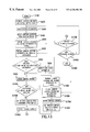
- FIG. 1 is a functional block diagram showing a first exemplary embodiment of the tactile guidance system according to this invention
- FIG. 2 shows a functional block diagram of one exemplary embodiment of the tactile direction device of this invention
- FIG. 3 shows one exemplary embodiment of the tactile surface device
- FIG. 4 shows a sectional view of the exemplary tactile direction device of FIG. 3
- FIG. 5 shows a functional block diagram of one exemplary embodiment of the guidance server of this invention
- FIG. 6 shows a functional block diagram of one exemplary embodiment of a location beacon in the location beacon network of this invention
- FIG. 7 illustrates how communication between the tactile direction device and the guidance server occurs
- FIG. 8 illustrates an exemplary embodiment of a look-up table for determining direction information
- FIG. 9 illustrates how a directional cue is determined
- FIG. 10 illustrates an exemplary mapping of navigational directions
- FIG. 11 illustrates an exemplary wide segmentation of a compass rose
- FIG. 12 illustrates an exemplary narrow segmentation of a compass rose
- FIG. 13 is a flowchart outlining one embodiment of a method for providing tactile guidance according to this invention.
- FIG. 14 is a flowchart outlining one method for determining direction information according to this invention.
- FIG. 15 is a flowchart outlining one exemplary method for using a relaxed compass rose to calculate a direction cue according to this invention
- FIG. 16 is a flowchart outlining one exemplary method for using a narrow compass rose to calculate a direction cue according to this invention
- FIG. 17 is a flowchart outlining one method for determining a revised heading according to this invention.
- FIG. 18 shows a functional block diagram of a second exemplary embodiment of the tactile direction device according to this invention.
- FIG. 19 is a functional block diagram showing a second exemplary embodiment of the tactile guidance system according to this invention.
- FIG. 20 shows a functional block diagram of a third exemplary embodiment of the tactile direction device according to this invention.
- a user upon entering a new environment, initializes a tactile direction device. After inputting a desired destination, the tactile direction device, communicating with a location beacon network and a guidance server, determines a heading in which the user must proceed to reach the desired destination. The tactile direction device, upon receiving directional information from the guidance server, activates a tactile surface that indicates to a user the direction to which the user must turn and, the direction in which the user must proceed in order to reach the desired destination.
- the tactile guidance systems and methods of this invention are designed to supplement a person's natural ability to navigate in the real world, rather than act as a substitute for those abilities. Most people only need occasional subtle confirmations indicating that they are proceeding in the right direction, or warnings alerting them that they are proceeding in the wrong direction.
- low-level directional aids By stimulating a surface of the tactile direction device, low-level directional aids can be relayed to a user. Since these directional aids require little to no focal activity, and could be processed as background or peripheral information, users can dedicate their full attention to the surrounding environment.
- FIG. 1 illustrates a tactile guidance system 100 according to this invention.
- the tactile guidance system 100 comprises a tactile direction device 200 , a guidance server 300 , a location beacon network 400 , wireless links 392 and 470 , and an optional wired or wireless link 394 .
- the tactile direction device 200 receives a desired destination input from the user or an outside source, as well as a current location input over the wireless link 470 from a location beacon 405 of the location beacon network 400 .
- the tactile direction device 200 forwards the current location information and the desired destination information to the guidance server 300 over the link 392 .
- the guidance server 300 determines the direction in which the tactile direction device 200 , i.e., the user, should proceed to arrive at the desired destination. Upon making this determination, the guidance server 300 transmits back to the tactile direction device 200 , over the wireless link 392 , the current location, the desired destination and direction information.
- the tactile direction device 200 upon receiving this direction information, determines the current heading of the tactile display device 200 and generates a revised heading, relative to the current heading of the tactile display device 200 .
- the revised heading is translated to point the user in the direction in which the user needs to proceed to eventually arrive at the desired destination.
- the tactile direction device 200 converts this direction cue to a control signal for a tactile surface.
- a tactile surface controller converts the control signal into a stimulus that can be sensed by the user.
- the location beacon network 400 includes a series of location beacons 405 , e.g., transmitters, where each location beacon 405 corresponds to a particular location within a navigable space. Each location beacon 405 within the location beacon network 400 transmits a signal corresponding to that particular location beacon's identifier. Whenever the tactile direction device 200 enters a space corresponding to a particular location beacon 405 , the location beacon identifier will be used to inform the tactile direction device 200 of its current position.
- the beacon location identifier may be provided to the tactile direction device 200 in a local coordinate system, such as, for example, a simple integer coordinate system for a building, or a building/column numbering system or the like, or expressed in a globally unique identifying format, such as, for example, a Universal Resource Locator, a GPS coordinate system, latitude or longitude, or the like.
- a local coordinate system such as, for example, a simple integer coordinate system for a building, or a building/column numbering system or the like
- a globally unique identifying format such as, for example, a Universal Resource Locator, a GPS coordinate system, latitude or longitude, or the like.
- the guidance server 300 is responsible for answering the received desired destination request from the tactile direction device 200 .
- the guidance server 300 upon receiving the current location information and the desired destination information, determines, for example with reference to a look-up table, a direction to the next location to which the user needs to proceed in route to the final destination.
- FIG. 2 illustrates the tactile direction device 200 in greater detail.
- the tactile direction device 200 comprises transmitter/receiver 210 , a controller 220 , a memory 230 , a destination identification device 240 , a direction determination circuit 250 , a compass 260 , a power supply 270 , a display device 280 , a tactile surface control circuit 290 , a tactile surface device 295 , a control/data bus 205 and an antenna 215 .
- destination identification data is input to the destination identification device 240 .
- This destination identification data corresponds to the desired destination of the user.
- the destination identification data can be input to the tactile direction device 200 in a plurality of ways.
- a user upon entering an office building for a meeting, a user could approach a reception area. Upon being greeted by the receptionist, the user can indicate that the user has a meeting in, for example, “Conference Room 4.” Upon receiving this request, the receptionist could activate a transmitter that forwards destination identification data corresponding to “Conference Room 4” to the tactile direction device 200 .
- the user upon entering a new environment, the user could proceed to a direction kiosk.
- This kiosk could, for example, show a map of the environment, such as, for example, an office building, that the user is in.
- the kiosk Upon selecting the desired destination at the kiosk, the kiosk could transfer the destination identification data to the tactile direction device 200 .
- the tactile direction device 200 could include an alphanumeric keypad for entering the destination identification data corresponding to the desired destination.
- the destination identification data Upon receipt by the tactile direction device 200 , the destination identification data is transferred via the antenna 215 and the transmitter/receiver 210 to the memory 230 at the direction of controller 220 .
- the destination identification device 240 can then retrieve the destination identification data from memory 230 as needed.
- the tactile direction device 200 is capable of receiving and storing destination identification data
- destination identification data can be transferred or shared between users.
- a first user could transmit the necessary desired destination identification data to a second user.
- This second user would activate the destination identification data for “The Deli” in the tactile direction device 200 , which could then guide the second user from the second user's current location to “The Deli.”
- the destination identification device 240 also performs a conversion to provide the user with a recognizable mnemonic, e.g., “The Deli,” corresponding to the destination identification data. Specifically, in addition to the destination identification data that is forwarded to the tactile direction device 200 corresponding to the desired destination, a human recognizable mnemonic corresponding to the destination identification data could also be forwarded to the tactile direction device 200 . This mnemonic is displayed in the display device 280 so the user is aware of the currently selected destination.
- a recognizable mnemonic e.g., “The Deli”
- the destination identification device 240 also functions as a “bookmark” type system for storing and retrieving, for example, frequently traveled-to destinations.
- a user via an input device, such as the above-described direction kiosk or alphanumeric keypad, selects a desired destination, or alternatively, for example, activates the tactile direction device 200 to store a current location, such as, for example, where the user's car is parked in a garage equipped with location beacons 405 .
- the user can then enter a mnemonic, such as, for example, “car”, corresponding to the selected input. If the user for any reason needs to return to the user's car, the user simply selects the “car” mnemonic in the tactile direction device 200 .
- the destination identification device 240 then converts the mnemonic into the coordinate system equivalent, and forwards this new destination identification data to the guidance server 300 .
- the tactile direction device 200 Upon receiving the destination identification data, the tactile direction device 200 detects its current location based on a signal received over the wireless link 470 from a location beacon 405 in the location beacon network 400 . This current location information is received over the antenna 215 and the transmitter/receiver 210 and stored under control of the controller 220 in the memory 230 over the control/data bus 205 . At the direction of the controller 220 , the current location is retrieved from the memory 230 . Furthermore, at the direction of the controller 220 , the destination identification data corresponding to a desired destination is retrieved from the memory 230 and both the current location and desired destination are transmitted by the transmitter/receiver 210 and the antenna 215 over the wireless link 392 to the guidance server 300 .
- the guidance server 300 returns the current location information, the desired destination information and direction information to the tactile direction device 200 .
- This data is received over the wireless link 392 , the antenna 215 and the transmitter/receiver 2120 and stored in the memory 230 .
- the direction determination circuit 250 determines whether new floor information was included with the direction information returned from the guidance server 300 . If new floor information was included, the direction determination circuit 250 retrieves the new floor information from the memory 230 . Under the control of the controller 220 , the new floor information is displayed on display device 280 . This allows a user to recognize that the user must traverse to a new floor to reach the desired destination.
- the tactile direction device 200 obtains a current heading from the compass 260 .
- the direction determination circuit 250 retrieves from the memory 230 the direction information received from the guidance server 300 and determines a direction cue. The direction cue is then forwarded to the tactile surface control circuit 290 , which activates at least one actuator in the tactile surface device 295 .
- the actuator indicates to a user the direction in which to proceed to reach the desired destination.
- the tactile direction device 200 is a transportable device, it comes with a self-contained power supply 270 .
- the power supply 270 can be any known or later developed device capable of supplying sufficient power to run the tactile direction device 200 including, but not limited to, batteries, rechargeable batteries, solar power or the like.
- the tactile display device 200 can be equipped with a speaker or other audio device or any other known or later developed device that is capable of generating an audible sound (not shown), that, at the direction of controller 220 , emits a tone if new floor information is received. Using this audio signal further removes a cognitive load from the user, since the user would not need to check the display device 280 unless a tone was heard.
- the tactile surface device 295 could retract all of the pegs 275 , raise all of the pegs 275 , vibrate or use some unique state of the tactile surface device 295 to indicate new floor information is being displayed on the display device 280 .
- FIG. 3 shows an exemplary embodiment of the outside shell of the tactile direction device 200 .
- the tactile direction device 200 is hand-held and includes an outer surface 255 , the display device 280 and the tactile surface device 295 , which includes a reference peg 265 and a plurality of movable pegs 275 .
- the tactile direction device 200 conveys the directional information to the user via the movable pegs 275 .
- the movable pegs 275 at the direction of the tactile surface control circuit 290 and the tactile surface device 295 , are raised and lowered to provide direction cues to the user.
- FIG. 3 illustrates an exemplary arrangement of the movable pegs 275 and the reference peg 265 in which four direction cues, i.e., forward, backward, left and right, correspond to the four movable pegs 275 .
- the center reference peg 265 provides a reference marker to assist the user in distinguishing which of the movable pegs 275 is raised.
- the center reference peg 265 need only provide a different feel than the movable pegs 275 and need not extend as far above the device surface 255 as any of the movable pegs 275 .
- a finger or thumb placed above the center reference point 265 and the movable pegs 275 could easily detect directional cues corresponding to the raising of one of the movable pegs 275 corresponding to a particular direction to be taken.
- the distance the movable pegs are raised could correspond to the amount of distance to be traveled. Therefore, as the distance to the desired location, or some intermediary destination, is reduced, the movable pegs 275 can make a corresponding change in height.
- the display device 280 is capable of displaying mnemonic or new floor information to a user.
- the display device 280 could be a liquid crystal display, a light emitting diode display, or the like.
- audible notification or tactile cueing could convey floor information to a user.
- FIG. 4 shows a cross-sectional view of the tactile direction device 200 shown in FIG. 3 .
- the cross-sectional view illustrates how the movable pegs 275 protrude through the surface 255 to come in contact with for example, a user's thumb or finger.
- the tactile surface device 295 moves each of the movable pegs 275 , for example, with a solenoid, at the direction of the tactile surface control circuit 290 .
- the tactile direction device 200 has been described as a distinct hand-held device, it should be understood that the tactile direction device 200 can be incorporated into any structure where it is capable of conveying navigational information to a user.
- the tactile direction device 200 can be incorporated into the arm of a wheel chair, a briefcase handle, the sole of a shoe, a pager, a cellular telephone, a PDA or other hand-held, palm-sized computer, a purse, a hat, a dedicated tactile direction device, or the like.
- FIG. 5 is a functional block diagram of one exemplary embodiment of the guidance server 300 .
- the guidance server 300 comprises a transmitter/receiver 310 , a controller 320 , a memory 330 , a mass storage device 340 , an I/O interface 350 , a navigation circuit 360 , a location management device 370 , a look-up table 380 , a control/data bus 305 , an antenna 390 , and the optional wired or wireless link 394 to a network.
- the guidance server 300 receives, over the wireless link 392 , the antenna 390 and the transmitter/receiver 310 , the current location and the desired destination information from the tactile direction device 200 .
- the current location and the desired destination information are transferred under control of the controller 320 over the control/data bus 305 to the memory 330 .
- the location management device 370 determines whether the desired destination is on a different floor than the current location. If the desired destination is not on another floor, the navigation circuit 360 , in cooperation with the look-up table 380 and the mass storage device 340 , and at the direction of the controller 320 , determines direction information identifying the next location beacon in route to the final destination.
- This direction information is then transmitted via the transmitter/receiver 310 and the antenna 390 over the wireless link 392 back to the tactile direction device 200 .
- the navigation circuit 360 can determine the direction needed to route the user to an interim destination that is in route to the final destination.
- the determination of how to guide the user to another floor may also be based on predetermined criteria or, for example, a specific users' requirements. For example, when the user initially enters the desired destination information, for example, at the directory kiosk, the user could additionally enter information indicating they require wheelchair accessible corridors. Accordingly, the desired destination information could be accompanied by a flag indicating that only navigation through wheelchair accessible routes is acceptable.
- the location management device 370 if the desired destination is on a different floor than the current location, the location management device 370 generates a new floor flag.
- the new floor flag indicates to the navigation circuit 360 that instead of determining the direction information to the desired destination, the direction information for guiding a user to a stairwell or to an elevator used to move to the new floor is needed.
- the navigation circuit 360 will generate direction information that could guide the user to, for example, the nearest elevator or stairwell. Therefore, if such predetermined criteria is present, for example, for wheelchair accessible routes, in the event a floor change is necessary, the navigation circuit 360 would automatically route the user to the appropriate elevator.
- the guidance server 300 can contain an optional link 394 .
- This optional link 394 can for example, connect a plurality of the guidance servers 300 in different areas of a large complex.
- a plurality of guidance servers 300 could interface with other guidance serves 300 to enable a user to pass from, for example, one building to another.
- the guidance server 300 could be connected to any one or more of the location beacons 405 in the location beacon network 400 via the optional link 394 .
- this link 394 is merely optional, and the location beacons within the location beacon network 400 are able to operate without direct interaction with the guidance server 300 .
- FIG. 6 is an exemplary block diagram of an exemplary embodiment of one location beacon 405 within the location beacon network 400 .
- each location beacon 405 within the location beacon network 400 comprises a transmitter/receiver 410 , a memory 420 , a controller 430 , an I/O interface 440 , a control/data bus 450 , an antenna 460 and the optional link 394 .
- Each location beacon 405 stores a location identifier in the memory 420 corresponding to that location beacon's location in an environment.
- a location identifier at the direction of the controller 430 , is continuously transmitted from the transmitter/receiver 410 and the antenna 460 .
- the location beacon 405 also contains an I/O interface 440 which can be connected via the optional link 394 to other location beacons 405 within the location beacon network 400 or to the guidance server 300 . It should be appreciated that the location beacon 405 can operate on a continuous basis, or be programmed to transmit the location identifier at some predetermined interval, as appropriate.
- FIG. 7 illustrates how communication between the tactile direction device 200 and the guidance server 300 occurs.
- a request 475 is forwarded from the tactile direction device 200 to the guidance server 300 via the link 470 .
- the request 475 contains the current location information and the desired destination information.
- the guidance server 300 receives this request, determines an appropriate course to the destination and returns an answer 485 to the tactile direction device 200 .
- the answer comprises the current location, the desired destination and the direction, with new floor information if appropriate, the user is to take to reach the next location in route to the final destination.
- Communication between the tactile direction device 200 and the guidance server 300 in this way has several advantages. Specifically, since the tactile direction device 200 does not contain a “tactile direction device identifier” the anonymity of the user operating any particular tactile direction device 200 can be preserved.
- a location beacon 405 can act as an intermediary “sub-station” which receives a request 475 , and forwards the request over the optional link 394 to the guidance server 300 .
- independent “sub-stations” or repeaters could be located throughout an environment as needed to ensure a clear communication path between the tactile direction device 200 and the guidance server 300 .
- FIG. 8 illustrates how the guidance server 300 determines the route to be used to guide the user to a desired destination.
- the guidance server 300 bases its direction determination on a look-up table.
- the look-up table contains a matrix of current locations and desired destinations as well as floor information, if applicable.
- the look-up table describes the topology of the environment supported by the guidance server 300 .
- the matrix of the look-up table provides, for each location beacon 405 supported by a particular guidance server 300 , the direction the user needs to take from that location beacon to reach any particular final destination.
- the look-up table will indicate that to proceed from the location beacon 2 to the desired destination location beacon 5 , the user holding that tactile direction device 200 should go east towards the location beacon 4 . From the location beacon 4 , the user holding the tactile direction device 200 will be informed to go north towards the location beacon 3 , and finally, once the user holding the tactile direction device arrives at the location beacon 3 , the user will be notified to head east to the desired destination location beacon 5 .
- FIGS. 9-12 illustrate how to determine the navigational cues to be generated by the tactile direction device 200 .
- FIG. 9 shows a view from the tactile direction device's perspective of the current heading ⁇ relative to a global frame of reference, such as magnetic north.
- the compass 260 provides the tactile direction device 200 with information pertaining to the orientation of the tactile direction device 200 in a global frame of reference defined by the earth's magnetic field.
- the guidance server 300 provides, on a request from the tactile direction device 200 , direction information giving the direction to the next location beacon 405 that should be visited on the route to the final destination.
- a revised heading value can be found representing the relative change in orientation the tactile direction device 200 needs to take to point to the next location along the route to the final destination.
- the tactile direction device 200 can retrieve the current heading ⁇ .
- the direction determination circuit 250 can determine any heading revision ⁇ , i.e., change in orientation, that may be required as:
- ⁇ is the heading direction to the next location beacon in the global frame of reference
- ⁇ is the current heading direction
- ⁇ is the heading revision, or change in orientation, needed to align the tactile direction device with the heading ⁇ to the next location beacon. Based on the heading revision, a direction cue for the tactile direction device 200 , i.e., forward, left, right or back, is determined.
- FIG. 10 illustrates that the accuracy of the tactile direction device 200 can be adjusted in accordance with, for example, the topographical characteristics of the location.
- the tactile direction device 200 can be assigned different mappings from the relative direction the tactile direction needs to be oriented in to the particular peg or pegs 275 that should be activated, corresponding to the desired accuracy of the directional cues.
- the mapping of a forward zone 505 that corresponds to activating the forward peg 275 can be adjusted depending on the type of environment the tactile direction device 200 may be in. If the tactile direction device 200 is in, for example, a complicated shop floor, the forward zone 505 may be narrowed to provide the user with more specificity as to the direction the user should proceed in.
- the forward zone 505 can be widened or relaxed, as illustrated in FIG. 10, so the user can simply navigate around, for example, dog legs in a hallway where minor deviations from the heading ⁇ to the next location beacon 405 occur, without receiving new direction cues.
- additional criteria may govern whether a relaxed or a narrow mapping of the direction cues may be desired. For example, each time the tactile direction device 200 enters a new zone, corresponding to a new location identifier received from a different location beacon 405 , the tactile direction device 200 could map a narrow orientation to the forward zone 505 in the tactile direction device 200 frame of reference. Once the user is oriented and traveling in the direction to reach the next location beacon, the mapping can be relaxed.
- the tactile direction device 200 For example, if the tactile direction device 200 has entered a new location, it will have received direction information indicating how that location should be traversed in order to reach the next location. In this case, the “forward” direction is mapped to a narrow arc of X degrees centered around the heading direction ⁇ to the next location in the global frame of reference. As a consequence of this mapping, the user must orient the tactile direction device 200 within X/2 degrees of the heading angle to the next location in order to obtain a forward direction cue.
- the mapping of the forward direction is relaxed to a wide or relaxed arc of Y degrees centered around the heading direction ⁇ to the next location in the global frame of reference.
- the user only need orient the device within Y/2 degrees of the heading direction ⁇ to the next location in order to obtain a forward cue, where Y>X.
- FIG. 11 illustrates how a wide or relaxed mapping is applied by the direction determination circuit 250 of the tactile direction device 200 .
- the forward zone 505 ⁇ is set to Y degrees.
- the device frame of reference is relaxed to orient the user within Y/2 degrees of the heading direction ⁇ to the next location beacon 405 . If the current heading direction ⁇ is within Y/2 degrees of the heading direction ⁇ to the next location beacon 405 , a revised direction cue does not need to be determined.
- the direction determination circuit 250 determines a new direction cue to indicate to a user the direction needed to align the tactile direction device 200 with the heading direction ⁇ .
- FIG. 12 illustrates how a narrow mapping is applied to the direction determination circuit 250 of the tactile direction device 200 .
- the forward zone 505 ⁇ is set to X degrees.
- the device frame of reference is relaxed to orient the user within X/2 degrees of the heading direction ⁇ to the next location beacon 405 .
- a revised direction cue does not need to be determined.
- the current heading direction ⁇ is greater than X/2 degrees from the heading direction ⁇ to the next location beacon 405 as illustrated by current heading direction 503
- a revised heading ⁇ is needed to align the tactile direction device 200 with the heading direction ⁇ to the next location beacon in the global frame of reference.
- the direction determination circuit 250 determines a new direction cue to indicate to a user the direction needed to align the tactile direction device 200 with the heading direction ⁇ .
- FIG. 13 is a flowchart outlining one exemplary embodiment of the method for providing tactile guidance using sensory supplementation according to this invention.
- Control begins in step S 100 .
- step S 200 the compass, the receiver and the tactile display device are initialized.
- step S 300 the desired destination is input.
- step S 400 the current location is detected from a location beacon. Control then continues to step S 500 .
- step S 500 the current location and the desired destination are transmitted to the guidance server.
- step S 600 the current location, the desired destination and the direction information to the next in route location are received from the guidance server.
- step S 700 a determination is made whether the direction information includes new floor information. If the direction information does not include new floor information, control jumps to step S 900 . Otherwise, control continues directly to step S 800 .
- step S 800 the new floor information is displayed, and an optional tone and/or a predetermined cue are activated. Control then continues to step S 900 .
- step S 900 the current heading is obtained from the compass.
- step S 1000 a determination is made whether a first or new destination has been input, or whether the tactile direction device has arrived in a new zone. If a new or first destination has not been input, or the tactile direction device has not arrived in a new zone, control jumps to step S 1500 . Otherwise, control continues to step S 1100 .
- step S 1100 the current location and desired destination are transmitted to the server.
- step S 1200 the current location, desired destination and the direction information are received from the server.
- step S 1300 a compass heading is obtained.
- step S 1400 a narrow compass rose is used to determine the direction cue. Control then jumps to step S 1600 .
- step S 1500 the relaxed compass rose is used to determine a direction cue. Control then continues to step S 1600 .
- step S 1600 the tactile surface is activated.
- step S 1700 a determination is made whether the tactile direction device has arrived at the desired destination. If the tactile direction device has not arrived at the desired destination, control jumps back to step S 900 . Otherwise, control continues to step S 1800 .
- step 1800 a determination is made whether a new destination has been input. If a new destination is has been input, control jumps back to step S 300 . Otherwise, control continues to step S 1900 , where the control sequence ends.
- FIG. 14 is a flowchart outlining one exemplary embodiment for a method for determining the direction information according to this invention.
- Control begins in step S 2000 .
- step S 2100 the current location and the desired destination information are received.
- step S 2200 a determination is made whether the desired destination is on a different floor than the current location. If the desired destination is on a different floor, control jumps to step S 2300 . Otherwise, control continues to step S 2600 .
- step S 2300 the floor change information is generated based on the received direction information.
- step S 2400 heading information to accomplish the floor change is determined.
- step S 2500 the current location, the desired destination, the direction and the floor information are transmitted to the tactile direction device. Control then jumps to step S 2800 .
- step S 2600 the route to the desired destination is determined.
- step S 2700 the current location, the desired destination and the direction information are transmitted to the tactile direction device. Control then continues to step S 2800 , where the control sequence ends.
- FIG. 15 is a flowchart outlining in greater detail how the relaxed compass rose is used to determine the direction cue in step S 1500 .
- control continues to step S 1510 .
- step S 1510 the “forward” direction is mapped to a wide arc (Y°).
- step S 1520 a determination is made whether the current heading is within Y/2° of the heading direction ⁇ . If the current heading is within Y/2° of the heading direction ⁇ , control continues to step S 1530 . Otherwise, control jumps to step S 1540 .
- step S 1530 the current direction cue is maintained or reactivated. Control then jumps to step S 1560 .
- step S 1540 the revised heading is determined. Then, in step S 1550 , a new direction cue is generated. Control then continues to step S 1560 , where control returns to step S 1600 .
- FIG. 16 is a flowchart outlining in greater detail how the narrow compass rose is used to determine the direction cue in step S 1400 .
- control continues to step S 1410 .
- step S 1410 the “forward” direction is mapped to a narrow arc (X°).
- step S 1420 a determination is made whether the current heading is within X/2° of the heading direction ⁇ . If the current heading is within X/2° of the heading direction ⁇ , control continues to step S 1430 . Otherwise, control jumps to step S 1440 .
- step S 1430 the current direction cue is maintained or reactivated. Control then jumps to step S 1460 .
- step S 1440 the revised heading is determined. Then, in step S 1450 , a new direction cue is generated. Control then continues to step S 1460 , where control returns to step S 1600 .
- FIG. 17 is flowchart outlining in greater detail the determined revised heading steps S 1440 and S 1540 .
- step S 1442 the current heading ⁇ is retrieved.
- step S 1444 the heading to the next location ⁇ is retrieved.
- step S 1446 the heading revision ⁇ needed to align the tactile direction device with the heading ⁇ to the next location beacon is determined. Control then continues to step S 1448 , where control returns to step S 1450 or step S 1550 respectively.
- the tactile direction device 200 is preferably implemented on a programmed general purpose computer.
- the tactile direction device 200 can also be implemented on a special purpose computer, a programmed microprocessor or microcontroller and peripheral integrated circuit elements, an ASIC or other integrated circuit, a digital signal processor, a hard-wired electronic or logic circuit such as a discrete element circuit, a programmable logic device such as a PLD, PLA, FPGA , PAL, or the like.
- a device capable of implementing a finite state machine that is in turn capable of implementing the flowcharts shown in FIGS. 13 and 15 - 17 can be used to implement the tactile guidance system.
- the guidance server 300 is preferably implemented on a programmed general purpose computer.
- the guidance server 300 can also be implemented on a special purpose computer, a programmed microprocessor or microcontroller and peripheral integrated circuit elements, an ASIC or other integrated circuit, a digital signal processor, a hard-wired electronic or logic circuit such as a discrete element circuit, a programmable logic device such as a PLD, PLA, FPGA, PAL, or the like.
- a device capable of implementing a finite state machine that is in turn capable of implementing the flowcharts shown in FIG. 14 can be used to implement the tactile guidance system.
- the location beacon 405 is preferably implemented on an ASIC or other integrated circuit.
- the location beacon 405 can also be implemented on a special purpose computer, programmed general purpose computer, a programmed microprocessor or microcontroller and peripheral integrated circuit elements, a digital signal processor, a hard-wired electronic or logic circuit such as a discrete element circuit, a programmable logic device such as a PLD, PLA, FPGA, PAL, or the like.
- any known or later developed device capable of receiving and/or transmitting information can be used to implement the location beacon 405 .
- the links 392 , 394 and 470 can be a wired or wireless link or any known element that is capable of supplying electronic data to and from the connected elements.
- the functions of the guidance server can be incorporated into the tactile direction device.
- the navigation circuitry can be fully incorporated into the tactile direction device.
- FIG. 18 illustrates such a second exemplary embodiment of the tactile direction device 201 .
- the tactile direction device 201 comprises the transmitter/receiver 210 , the controller 220 , the memory 230 , the destination identification device 240 , the direction determination circuit 250 , the compass 260 , the power supply 270 , the display device 280 , the tactile surface control circuit 290 , the tactile surface device 295 of the first exemplary embodiment shown in FIG. 2, as well as the control/data bus 205 and the antenna 215 , a location management device 371 , a navigation circuit 361 and a look-up table 381 .
- the amount of communication between the tactile direction device 201 and the guidance server 300 can be reduced.
- the tactile direction device 200 receives the desired destination information. This desired destination information and current location are then transmitted to the guidance server 300 .
- the guidance server 300 returns to the tactile direction device 200 only the current location information, the desired destination information and the direction information to direct the user to the next location en route to the final destination.
- the guidance server 300 can operate as previously discussed, or the guidance server 300 can simply be a storage location for the look-up table data.
- destination identification data is input to the destination identification device 240 .
- This destination identification data corresponds to the desired destination of the user.
- the destination identification data can be input to the tactile direction device 201 in any one of a plurality of ways.
- data stored in the look-up table 380 of the guidance server 300 can be downloaded to the look-up table 381 in the tactile direction device 201 . Therefore, with reference to the look-up table 381 , the navigation circuit 361 can determine the direction needed to route the user to an interim destination that is in route to the final destination.
- a user While riding on a train in a subway system, a user arrives at a subway station where the user must switch to a new train. Upon disembarking from the train, data stored in the look-up table 380 is automatically transferred to the look-up table 381 . The user could then approach a subway attendant and inquire as to the platform for the train to “Oxford Street.” Upon receiving this request, the attendant could activate a transmitter that forwards destination identification data corresponding to “Oxford Street” to the tactile direction device 201 .
- the user upon entering a new environment, the user could proceed to a direction kiosk.
- This kiosk could, for example, show a map of the environment, such as, for example, a nature park, that the user is in.
- the kiosk Upon selecting the desired destination at the kiosk, the kiosk could transfer the destination identification data as well as the data stored in the look-up table 380 to the tactile direction device 201 .
- the destination identification data is transferred via the antenna 215 and the transmitter/receiver 210 to the memory 230 at the direction of the controller 220 .
- the look-up table data is transferred via the antenna 215 and the transmitter/receiver 210 to the look-up table 381 also at the direction of the controller 220 .
- the destination identification device 240 and the navigation circuit 361 can then retrieve the destination identification data and look-up table data from the memory 230 and the look-up table 381 , respectively, as needed.
- the tactile direction device 201 Upon receiving the destination identification data and look-up table data, the tactile direction device 201 detects its current location based on a signal received over the wireless link 470 from a location beacon 405 in the location beacon network 400 . This current location information is received over the antenna 215 and the transmitter/receiver 210 and stored under control of the controller 220 in the memory 230 over the control/data bus 205 . At the direction of the controller 220 , the current location is retrieved from the memory 230 . Furthermore, at the direction of the controller 220 , the destination identification data corresponding to a desired destination is retrieved from the 230 and both the current location and desired destination are forwarded to the navigation circuit 361 .
- the navigation circuit 361 returns the direction information to the direction determination circuit 250 for storage in memory 230 .
- the direction determination circuit 250 determines whether new floor information was included with the direction information returned from the navigation circuit 361 . If new floor information was included, the direction determination circuit 250 retrieves the new floor information from the 230 . Under the control of the controller 220 , the new floor information is displayed on display device 280 . This allows a user to recognize that the user must traverse to a new floor to reach the desired destination.
- the tactile direction device 201 obtains a current heading from the compass 260 .
- the direction determination circuit 250 retrieves from the memory 230 the direction information received from the navigation circuit 361 and determines a direction cue.
- the direction cue is then forwarded to the tactile surface control circuit 290 , which activates at least one actuator in the tactile surface device 295 .
- the actuator indicates to a user the direction in which to proceed to reach the desired destination.
- the first exemplary embodiment describes systems and methods where the current location information, the desired destination information and the direction information are communicated between the tactile direction device and the guidance server 300 .
- duplicating the data stored in the look-up table 380 into the look-up table 381 of the tactile direction device 200 communication between tactile direction device 200 and the guidance server 300 can be reduced. Instead of communication between the tactile guidance device 200 and the guidance server 300 occurring each time updated direction information is requested from the tactile direction device 200 , communication between the tactile direction device 201 and the guidance server 300 need occur only once. During this communication, for example, during initialization, the guidance server 300 will transfer all the data in look-up table 380 to the tactile direction device 201 . Therefore, since the tactile direction device 201 includes the navigation circuit 361 and the location management device 371 , the tactile direction device 201 is capable of determining the direction information without any further communication with the guidance server 300 .
- This initial download technique could prove beneficial in “noisy” environments. For example, on an industrial shop floor where radio-frequency interference is common, transmitting of the data stored in look-up table 380 from the guidance server 300 to the tactile direction device 201 at a particular “tactile direction device download station” could insure that the interference does not effect navigation on the shop floor. Additionally, in an environment such as a mine, communication between the tactile direction device 201 and the guidance server 300 may not be easily implemented. Therefore, downloading all or a portion of the data from the look-up table 380 to the tactile direction device 201 eliminates potential communication difficulties between the two devices.
- FIGS. 13-17 could be modified to accommodate a tactile direction device 201 that includes the navigation circuit 361 , location management device 371 and look-up table 381 .
- a tactile direction device 201 that includes the navigation circuit 361 , location management device 371 and look-up table 381 .
- the location beacon need not actually be an active beacon, i.e., a transmitter, in the traditional sense. That is, in contrast to the location beacons 405 described above, the location beacon can be a passive identification carrying device such as a label containing a bar code or a color code. For example, as a user passes such an identification carrying device, the user places the tactile direction device 200 or 201 within the sensible area of the location identifier to provide the tactile direction device 200 or 201 with the current location information.
- FIG. 19 illustrates a second exemplary tactile guidance system 101 according to this invention.
- the tactile guidance system 101 comprises a tactile direction device 202 , a guidance server 300 , a plurality of location identifiers and a wireless link 392 .
- the tactile direction device 202 and guidance server 300 operate as previously discussed.
- the location identifier 401 passively identifies the current location of a user. As a user navigates through an environment, the user places the tactile direction device 202 into the sensible area of the location identifier 401 . As the tactile direction device 202 is placed in the sensible area of the location identifier 401 , the tactile direction device reads the current location information contained in the location identifier 401 .
- the location identifier 401 could be a bar code, a color code, a magnetic strip, an inductive or capacitive device, an optically readable device, or any other known or later developed device that is capable of passively identifying a location.
- a location identifier 401 can be anything that is capable of storing a readable location identifier.
- FIG. 20 illustrates one exemplary embodiment of the tactile direction device 202 that has been adapted to read the passive location identifiers 401 .
- the tactile direction device 202 comprises the transmitter/receiver 210 , the controller 220 , the memory 230 , the destination identification device 240 , the direction determination circuit 250 , the compass 260 , the power supply 270 , the display device 280 , the tactile surface control circuit 290 , the tactile surface device 295 , the control/data bus 205 , and an antenna 215 , as well as a location identifier reader 285 .
- the location identifier reader 285 replaces the transmitter/receiver 210 and the wireless link 470 for the purposes of obtaining the current location of a user. For example, if the location identifier 401 is a bar code, the location identifier reader 285 is a bar code scanner.
- the user associates the tactile direction device 201 with the location identifier 401 in a manner such that the location identifier reading device 285 is capable of reading the current location information from the location identifier 401 .
- this embodiment may be helpful in environments where radio or optical communication is difficult, or where it is an economical or physically difficult to install radio-frequency or optically emitting active location beacons, such as in an old building.
- the location identifier reading device 285 and the location identifier 401 are not limited to a bar code scanner and a bar code, respectively. That is, the location identifier 401 can be a device such as a microchip or other device capable of carrying information based on its mechanical, electrical or magnetic properties. For example, the location identifier 401 could maintain or respond to an electric or magnetic field. The location identifier 401 would then produce an electromagnetic field into which the location identifier reading device 285 can be placed.
- the location identifier reading device 285 When the location identifier reading device 285 is placed in the sensible area of the location identifier 401 , the location identifier reading device 285 becomes capacitively, inductively, or otherwise electromagnetically coupled to the location identifier 401 and the information can be extracted from the location identifier 401 by the location identifier reading device 285 .
- FIGS. 13-17 could be modified to accommodate passive location identifiers.
- a user instead of receiving a current location from a location beacon, a user would be required to positively interact with the location identifier 401 by ensuring that the tactile direction device 201 is placed into the sensible area of the location identifier 401 .
- control would continue as previously described until a new location identifier is encountered. Then, again, the user would positively interact with the location identifier 401 to ensure that location identifier reading device 285 reads the updated current location.
- any combination of active location beacons, passive location identifiers, “one-time” communication operation between the tactile direction device 201 and the guidance server 300 or multiple communication operation between the tactile direction device 200 or 201 and the guidance server 300 can be formed.
Abstract
Description
Claims (69)
Priority Applications (2)
| Application Number | Priority Date | Filing Date | Title |
|---|---|---|---|
| US09/301,594 US6320496B1 (en) | 1999-04-29 | 1999-04-29 | Systems and methods providing tactile guidance using sensory supplementation |
| JP2000128720A JP4193327B2 (en) | 1999-04-29 | 2000-04-28 | SYSTEM AND METHOD FOR PROVIDING NAVIGATION SUPPORT TO USER, TACTUAL DIRECTION DEVICE FOR PROVIDING NAVIGATION TO USER THROUGH DIRECTION CUE, AND METHOD FOR PROVIDING NAVIGATION TO USER via Tactile Direction Indicator |
Applications Claiming Priority (1)
| Application Number | Priority Date | Filing Date | Title |
|---|---|---|---|
| US09/301,594 US6320496B1 (en) | 1999-04-29 | 1999-04-29 | Systems and methods providing tactile guidance using sensory supplementation |
Publications (1)
| Publication Number | Publication Date |
|---|---|
| US6320496B1 true US6320496B1 (en) | 2001-11-20 |
Family
ID=23164043
Family Applications (1)
| Application Number | Title | Priority Date | Filing Date |
|---|---|---|---|
| US09/301,594 Expired - Lifetime US6320496B1 (en) | 1999-04-29 | 1999-04-29 | Systems and methods providing tactile guidance using sensory supplementation |
Country Status (2)
| Country | Link |
|---|---|
| US (1) | US6320496B1 (en) |
| JP (1) | JP4193327B2 (en) |
Cited By (106)
| Publication number | Priority date | Publication date | Assignee | Title |
|---|---|---|---|---|
| US20020101458A1 (en) * | 2001-01-31 | 2002-08-01 | Microsoft Corporation | Navigational interface for mobile and wearable computers |
| US20020101441A1 (en) * | 2001-01-31 | 2002-08-01 | Microsoft Corporation | Input device with pattern and tactile feedback for computer input and control |
| US20020128021A1 (en) * | 1999-07-23 | 2002-09-12 | Dan Kikinis | Enhanced weather and traffic information from mobile communication devices |
| US20020138264A1 (en) * | 2001-03-21 | 2002-09-26 | International Business Machines Corporation | Apparatus to convey depth information in graphical images and method therefor |
| US6505121B1 (en) * | 2001-08-01 | 2003-01-07 | Hewlett-Packard Company | Onboard vehicle navigation system |
| US20030033079A1 (en) * | 2001-08-11 | 2003-02-13 | Endicott William L. | Computer-implemented system and method for wayfinding |
| WO2003050557A2 (en) * | 2001-12-07 | 2003-06-19 | Dashsmart Investments, Llc | Portable navigation and communication systems |
| US20030158650A1 (en) * | 2000-06-29 | 2003-08-21 | Lutz Abe | Method and mobile station for route guidance |
| WO2003079141A2 (en) * | 2002-03-12 | 2003-09-25 | Senseboard, Inc. | Data input device |
| US20040005900A1 (en) * | 2002-07-05 | 2004-01-08 | Martin Zilliacus | Mobile terminal interactivity with multimedia programming |
| US20040147244A1 (en) * | 2001-05-04 | 2004-07-29 | Raisanen Veikko Lauri | Method, device and system to show heading in a cellular network |
| US20040224703A1 (en) * | 2003-05-09 | 2004-11-11 | Takaki Steven M. | Method and system for enhancing venue participation by venue participants |
| US20040230666A1 (en) * | 2003-05-14 | 2004-11-18 | Microsoft Corporation | Method, system, and computer-readable medium for communicating results to a data query in a computer network |
| US20040246135A1 (en) * | 2003-06-09 | 2004-12-09 | Carey Harold Ralph | Traveller |
| US20050033507A1 (en) * | 2003-07-07 | 2005-02-10 | Kunihiko Fukui | Vehicle navigation system |
| US20050060088A1 (en) * | 2003-07-10 | 2005-03-17 | University Of Florida Research Foundation, Inc. | Pedestrian navigation and spatial relation device |
| US20050108195A1 (en) * | 2002-05-07 | 2005-05-19 | Microsoft Corporation | Method, system, and apparatus for processing information based on the discovery of semantically labeled strings |
| US20050164148A1 (en) * | 2004-01-28 | 2005-07-28 | Microsoft Corporation | Tactile overlay for an imaging display |
| US20050279551A1 (en) * | 2004-06-21 | 2005-12-22 | Lopresti Edmund F | Power apparatus for wheelchairs |
| US20060016503A1 (en) * | 2004-07-20 | 2006-01-26 | Blind Faith School Of Music And Art | Method of and loom for teaching braille |
| US20060196569A1 (en) * | 2005-03-04 | 2006-09-07 | Mayster Jennifer J | Method of weaving braille and woven braille textile |
| US20070026802A1 (en) * | 2005-07-28 | 2007-02-01 | Inventio Ag | Method of Guiding a User in an Environment, Particularly in a Building |
| US20070093944A1 (en) * | 2005-10-20 | 2007-04-26 | Lee Hugh T | Tactile device and method using sequential actuation |
| US20070129883A1 (en) * | 2005-12-05 | 2007-06-07 | Ming-Jen Kuo | Method and apparatus for walk guidance |
| US20070136261A1 (en) * | 2002-06-28 | 2007-06-14 | Microsoft Corporation | Method, System, and Apparatus for Routing a Query to One or More Providers |
| US20070149156A1 (en) * | 2005-12-28 | 2007-06-28 | Kabushiki Kaisha Toshiba | Information processing apparatus and control method thereof |
| US20070268116A1 (en) * | 2006-05-22 | 2007-11-22 | Microsoft Corporation | Position based tactile reporting |
| WO2008026877A1 (en) * | 2006-08-30 | 2008-03-06 | Electronics And Telecommunications Research Institute | Method and apparatus for navigation service |
| US20080074321A1 (en) * | 2000-10-16 | 2008-03-27 | Harris Scott C | Position Privacy in an Electronic Device |
| US20080120029A1 (en) * | 2006-02-16 | 2008-05-22 | Zelek John S | Wearable tactile navigation system |
| US20080140314A1 (en) * | 2006-12-06 | 2008-06-12 | Park Kenneth J | Device orientation navigation system for mobile electronic device |
| DE102007004041A1 (en) | 2007-01-22 | 2008-07-24 | Deutsche Telekom Ag | Mobile navigation device for multimodal outputting information, has transferring unit with spinner rotated around axis, so that forces are controlled to render instructions, and surface forms are passed over housing to render instructions |
| US20080174415A1 (en) * | 2006-12-15 | 2008-07-24 | Honda Motor Co., Ltd. | Vehicle state information transmission apparatus using tactile device |
| US20080180267A1 (en) * | 2007-01-25 | 2008-07-31 | Fujitsu Component Limited | Direction indicator system, and electric wheelchair, walking stick, and game controller utilizing said direction indicator system |
| US20080319598A1 (en) * | 2007-06-20 | 2008-12-25 | Fujitsu Component Limited | Direction guiding apparatus and direction guiding method |
| US20090076723A1 (en) * | 2007-09-14 | 2009-03-19 | Palm, Inc. | Targeting Location Through Haptic Feedback Signals |
| US20090128376A1 (en) * | 2007-11-20 | 2009-05-21 | Motorola, Inc. | Method and Apparatus for Controlling a Keypad of a Device |
| US20090132093A1 (en) * | 2007-08-21 | 2009-05-21 | Motorola, Inc. | Tactile Conforming Apparatus and Method for a Device |
| US20090171572A1 (en) * | 2006-05-29 | 2009-07-02 | Clement Alteresco | Navigation Aid System |
| DE102008005164A1 (en) * | 2008-01-19 | 2009-07-23 | Arkadij Gershman | Contactless object identification and direction to object determination method for e.g. blind person during shopping, involves observing signals of objects, detecting object, and identifying and determining direction to object if necessary |
| US20090212974A1 (en) * | 2008-02-25 | 2009-08-27 | Denso International America, Inc. | Parking aid notification by vibration |
| US20100013613A1 (en) * | 2008-07-08 | 2010-01-21 | Jonathan Samuel Weston | Haptic feedback projection system |
| US20100063724A1 (en) * | 2008-09-10 | 2010-03-11 | International Business Machines Corporation | People guidance using kiosk and user id |
| US7707496B1 (en) | 2002-05-09 | 2010-04-27 | Microsoft Corporation | Method, system, and apparatus for converting dates between calendars and languages based upon semantically labeled strings |
| US7707024B2 (en) | 2002-05-23 | 2010-04-27 | Microsoft Corporation | Method, system, and apparatus for converting currency values based upon semantically labeled strings |
| US7711550B1 (en) | 2003-04-29 | 2010-05-04 | Microsoft Corporation | Methods and system for recognizing names in a computer-generated document and for providing helpful actions associated with recognized names |
| US7712024B2 (en) | 2000-06-06 | 2010-05-04 | Microsoft Corporation | Application program interfaces for semantically labeling strings and providing actions based on semantically labeled strings |
| US7716676B2 (en) | 2002-06-25 | 2010-05-11 | Microsoft Corporation | System and method for issuing a message to a program |
| US7716163B2 (en) | 2000-06-06 | 2010-05-11 | Microsoft Corporation | Method and system for defining semantic categories and actions |
| US7739588B2 (en) | 2003-06-27 | 2010-06-15 | Microsoft Corporation | Leveraging markup language data for semantically labeling text strings and data and for providing actions based on semantically labeled text strings and data |
| US7742048B1 (en) | 2002-05-23 | 2010-06-22 | Microsoft Corporation | Method, system, and apparatus for converting numbers based upon semantically labeled strings |
| US20100174483A1 (en) * | 2009-01-07 | 2010-07-08 | Samsung Electronics Co., Ltd. | Method and apparatus for road guidance using mobile terminal |
| US7770102B1 (en) | 2000-06-06 | 2010-08-03 | Microsoft Corporation | Method and system for semantically labeling strings and providing actions based on semantically labeled strings |
| US7778816B2 (en) | 2001-04-24 | 2010-08-17 | Microsoft Corporation | Method and system for applying input mode bias |
| US7783614B2 (en) | 2003-02-13 | 2010-08-24 | Microsoft Corporation | Linking elements of a document to corresponding fields, queries and/or procedures in a database |
| US7788590B2 (en) | 2005-09-26 | 2010-08-31 | Microsoft Corporation | Lightweight reference user interface |
| US7788602B2 (en) | 2000-06-06 | 2010-08-31 | Microsoft Corporation | Method and system for providing restricted actions for recognized semantic categories |
| US20100271340A1 (en) * | 2009-04-22 | 2010-10-28 | Funai Electric Co., Ltd. | Rotary Input Device and Electronic Equipment |
| US7827546B1 (en) | 2002-06-05 | 2010-11-02 | Microsoft Corporation | Mechanism for downloading software components from a remote source for use by a local software application |
| EP1901039A3 (en) * | 2006-09-13 | 2010-12-01 | NEC CASIO Mobile Communications, Ltd. | Mobile terminal device and program |
| US20110068981A1 (en) * | 2009-09-18 | 2011-03-24 | TEECOM Design Group | Apparatus and Method for Constructing and Utilizing a Beacon Location Database |
| US20110087451A1 (en) * | 2007-02-21 | 2011-04-14 | Johnson Controls Technology Company | Compass calibration system and method |
| US7992085B2 (en) | 2005-09-26 | 2011-08-02 | Microsoft Corporation | Lightweight reference user interface |
| US20120116672A1 (en) * | 2010-11-10 | 2012-05-10 | Qualcomm Incorporated | Haptic based personal navigation |
| US20120136569A1 (en) * | 2010-11-30 | 2012-05-31 | International Business Machines Corporation | Method, device and computer program for mapping moving direction by sounds |
| US20130049957A1 (en) * | 2011-08-26 | 2013-02-28 | Sony Corporation | Mobile terminal apparatus and orientation presentment method |
| WO2013039510A1 (en) * | 2011-09-16 | 2013-03-21 | Empire Technology Development Llc | Remote movement guidance |
| US8462049B2 (en) | 2009-09-18 | 2013-06-11 | Teecom | Apparatus and method for constructing and utilizing a beacon location database |
| US20130218456A1 (en) * | 2006-02-16 | 2013-08-22 | John S. Zelek | Wearable tactile navigation system |
| US8588870B1 (en) * | 2010-10-15 | 2013-11-19 | Sprint Spectrum L.P. | Method and system for reducing resource consumption to extend battery life based on an estimated time to destination |
| US8706708B2 (en) | 2002-06-06 | 2014-04-22 | Microsoft Corporation | Providing contextually sensitive tools and help content in computer-generated documents |
| US20140297184A1 (en) * | 2013-03-28 | 2014-10-02 | Fujitsu Limited | Guidance apparatus and guidance method |
| WO2014170539A1 (en) * | 2013-04-17 | 2014-10-23 | Nokia Corporation | Haptic device for pedestrian navigation |
| US20140379251A1 (en) * | 2012-06-26 | 2014-12-25 | Jonathan Louis Tolstedt | Virtual walking stick for the visually impaired |
| US9091561B1 (en) | 2013-10-28 | 2015-07-28 | Toyota Jidosha Kabushiki Kaisha | Navigation system for estimating routes for users |
| US20150241238A1 (en) * | 2014-02-26 | 2015-08-27 | Blazer and Flip Flops, Inc. dba The Experience Engine | Live branded dynamic mapping |
| US9141852B1 (en) | 2013-03-14 | 2015-09-22 | Toyota Jidosha Kabushiki Kaisha | Person detection and pose estimation system |
| CN105091900A (en) * | 2015-08-11 | 2015-11-25 | 上海交通大学 | Automatic human body navigation system and method for reducing thought loads |
| US9349301B2 (en) | 2011-01-28 | 2016-05-24 | Empire Technology Development Llc | Sensor-based movement guidance |
| US9370459B2 (en) | 2009-06-19 | 2016-06-21 | Andrew Mahoney | System and method for alerting visually impaired users of nearby objects |
| JP2016205937A (en) * | 2015-04-20 | 2016-12-08 | 英和 藤川 | Navigation system |
| US9536452B2 (en) * | 2015-05-13 | 2017-01-03 | Abl Ip Holding Llc | System and method to assist users having reduced visual capability utilizing lighting device provided information |
| US9613505B2 (en) | 2015-03-13 | 2017-04-04 | Toyota Jidosha Kabushiki Kaisha | Object detection and localized extremity guidance |
| DE102015222173A1 (en) * | 2015-11-11 | 2017-05-11 | Robert Bosch Gmbh | Signaling device for a navigation system |
| US9702723B2 (en) | 2012-03-01 | 2017-07-11 | Nokia Technologies Oy | Method and apparatus for receiving user estimation of navigational instructions |
| US9741022B2 (en) | 2014-02-26 | 2017-08-22 | Blazer and Flip Flops, Inc. | Parental controls |
| US9801778B2 (en) | 2009-06-19 | 2017-10-31 | Andrew Mahoney | System and method for alerting visually impaired users of nearby objects |
| US9813855B2 (en) | 2015-04-23 | 2017-11-07 | Blazer and Flip Flops, Inc. | Targeted venue message distribution |
| US9820103B2 (en) | 2014-01-22 | 2017-11-14 | Lenovo (Singapore) Pte. Ltd. | Direction assistance based on personal experience |
| US9906909B2 (en) | 2015-05-01 | 2018-02-27 | Blazer and Flip Flops, Inc. | Map based beacon management |
| US9949232B1 (en) | 2017-07-28 | 2018-04-17 | Bank Of America Corporation | Network device loss prevention using a distributed wireless network |
| US10012508B2 (en) * | 2015-03-04 | 2018-07-03 | Lenovo (Singapore) Pte. Ltd. | Providing directions to a location in a facility |
| US10024681B2 (en) | 2015-07-02 | 2018-07-17 | Walmart Apollo, Llc | Tactile navigation systems and methods |
| US10113877B1 (en) * | 2015-09-11 | 2018-10-30 | Philip Raymond Schaefer | System and method for providing directional information |
| US10129728B2 (en) | 2015-12-07 | 2018-11-13 | Blazer and Flip Flops, Inc. | Wearable device |
| US10210542B2 (en) | 2014-02-26 | 2019-02-19 | Blazer and Flip Flops, Inc. | Venue guest device message prioritization |
| CN109976517A (en) * | 2014-09-02 | 2019-07-05 | 苹果公司 | Pre- sharp prompt is provided to the user of electronic equipment |
| US20190281415A1 (en) * | 2018-03-09 | 2019-09-12 | Kabushiki Kaisha Toshiba | Guidance system and information processing device |
| CN110622628A (en) * | 2017-03-15 | 2019-12-27 | 香港物流及供应链管理应用技术研发中心 | Radio frequency communication guiding device |
| US10839425B2 (en) | 2016-02-19 | 2020-11-17 | At&T Intellectual Property I, L.P. | Commerce suggestions |
| US11030639B1 (en) | 2014-06-20 | 2021-06-08 | Wells Fargo Bank, N.A. | Beacon mall experience |
| US11144759B1 (en) * | 2020-05-12 | 2021-10-12 | Lenovo (Singapore) Pte. Ltd. | Presentation of graphical objects on display based on input from rear-facing camera |
| US11318050B2 (en) | 2018-01-24 | 2022-05-03 | American Printing House for the Blind, Inc. | Navigation assistance for the visually impaired |
| US11526916B2 (en) | 2015-04-28 | 2022-12-13 | Blazer and Flip Flops, Inc. | Intelligent prediction of queue wait times |
| US11549819B2 (en) * | 2018-05-30 | 2023-01-10 | International Business Machines Corporation | Navigation guidance using tactile feedback implemented by a microfluidic layer within a user device |
| US11568640B2 (en) | 2019-09-30 | 2023-01-31 | Lenovo (Singapore) Pte. Ltd. | Techniques for providing vibrations at headset |
Families Citing this family (9)
| Publication number | Priority date | Publication date | Assignee | Title |
|---|---|---|---|---|
| JP2004212146A (en) * | 2002-12-27 | 2004-07-29 | Sumitomo Precision Prod Co Ltd | Dead reckoning navigation system and dead reckoning navigation for walker |
| JP4983384B2 (en) * | 2007-05-15 | 2012-07-25 | カシオ計算機株式会社 | Body-mounted electronic equipment |
| JP2008286546A (en) * | 2007-05-15 | 2008-11-27 | Casio Comput Co Ltd | Wearable electronic device |
| JP4910991B2 (en) * | 2007-11-08 | 2012-04-04 | 株式会社デンソー | Parking lot guidance system |
| JP6445266B2 (en) * | 2014-07-09 | 2018-12-26 | Necプラットフォームズ株式会社 | Blind person guidance system |
| JP2018087742A (en) * | 2016-11-29 | 2018-06-07 | バリ トレーディング カンパニー リミテッド | Smart navigation system utilizing smart navigation footwear |
| JP6909386B2 (en) * | 2018-04-24 | 2021-07-28 | 株式会社デンソー | Car finder system |
| JP2020091112A (en) * | 2018-12-03 | 2020-06-11 | 株式会社デンソー | Force presentation system, portable terminal, and force presentation program |
| JP2020091111A (en) * | 2018-12-03 | 2020-06-11 | 株式会社デンソー | Force presentation system and force presentation program |
Citations (18)
| Publication number | Priority date | Publication date | Assignee | Title |
|---|---|---|---|---|
| US3736551A (en) | 1970-11-16 | 1973-05-29 | Us Navy | Swimmers tactile command navigation apparatus |
| US3902687A (en) | 1973-06-25 | 1975-09-02 | Robert E Hightower | Aircraft indicator system |
| US4044350A (en) | 1974-08-22 | 1977-08-23 | Oleg Tretiakoff | Electromechanical transducer for relief display panel |
| US4191945A (en) | 1978-01-16 | 1980-03-04 | Charlesworth David V | Tactile indicating device |
| US4194190A (en) | 1977-10-11 | 1980-03-18 | Compagnie International Pour L'informatique | Arrangement for converting digital signals representing characters into a self-locking dot representation |
| US4215490A (en) | 1977-11-16 | 1980-08-05 | Fewell William B | Braille deaf-blind communicators |
| US4473356A (en) | 1983-08-29 | 1984-09-25 | Telesensory Systems, Inc. | Electromechanical braille cell and method of operating same |
| US4586904A (en) | 1984-03-30 | 1986-05-06 | Siemens Aktiengesellschaft | Device for forming tactile display |
| US4871992A (en) | 1988-07-08 | 1989-10-03 | Petersen Robert C | Tactile display apparatus |
| US5144294A (en) * | 1990-10-17 | 1992-09-01 | Ldj Industries, Inc. | Radio frequency message apparatus for aiding ambulatory travel of visually impaired persons |
| US5508699A (en) * | 1994-10-25 | 1996-04-16 | Silverman; Hildy S. | Identifier/locator device for visually impaired |
| US5616901A (en) | 1995-12-19 | 1997-04-01 | Talking Signs, Inc. | Accessible automatic teller machines for sight-impaired persons and print-disabled persons |
| US5623358A (en) | 1995-06-30 | 1997-04-22 | Madey; Julius M. J. | Discriminating infrared signal detector and systems utilizing the same |
| US5627547A (en) | 1995-04-07 | 1997-05-06 | Delco Electronics Corporation | Mapless GPS navigation system in vehicle entertainment system |
| US5638060A (en) | 1992-10-15 | 1997-06-10 | Yazaki Corporation | System switch device |
| US5685721A (en) | 1995-11-06 | 1997-11-11 | American Research Corporation Of Virginia | Refreshable braille-cell display implemented with shape memory alloys |
| US5774828A (en) | 1995-04-07 | 1998-06-30 | Delco Electronics Corporation | Mapless GPS navigation system with user modifiable data base |
| US5939981A (en) * | 1998-01-28 | 1999-08-17 | Renney; Marjorie | Item locator with attachable receiver/transmitter |
-
1999
- 1999-04-29 US US09/301,594 patent/US6320496B1/en not_active Expired - Lifetime
-
2000
- 2000-04-28 JP JP2000128720A patent/JP4193327B2/en not_active Expired - Fee Related
Patent Citations (18)
| Publication number | Priority date | Publication date | Assignee | Title |
|---|---|---|---|---|
| US3736551A (en) | 1970-11-16 | 1973-05-29 | Us Navy | Swimmers tactile command navigation apparatus |
| US3902687A (en) | 1973-06-25 | 1975-09-02 | Robert E Hightower | Aircraft indicator system |
| US4044350A (en) | 1974-08-22 | 1977-08-23 | Oleg Tretiakoff | Electromechanical transducer for relief display panel |
| US4194190A (en) | 1977-10-11 | 1980-03-18 | Compagnie International Pour L'informatique | Arrangement for converting digital signals representing characters into a self-locking dot representation |
| US4215490A (en) | 1977-11-16 | 1980-08-05 | Fewell William B | Braille deaf-blind communicators |
| US4191945A (en) | 1978-01-16 | 1980-03-04 | Charlesworth David V | Tactile indicating device |
| US4473356A (en) | 1983-08-29 | 1984-09-25 | Telesensory Systems, Inc. | Electromechanical braille cell and method of operating same |
| US4586904A (en) | 1984-03-30 | 1986-05-06 | Siemens Aktiengesellschaft | Device for forming tactile display |
| US4871992A (en) | 1988-07-08 | 1989-10-03 | Petersen Robert C | Tactile display apparatus |
| US5144294A (en) * | 1990-10-17 | 1992-09-01 | Ldj Industries, Inc. | Radio frequency message apparatus for aiding ambulatory travel of visually impaired persons |
| US5638060A (en) | 1992-10-15 | 1997-06-10 | Yazaki Corporation | System switch device |
| US5508699A (en) * | 1994-10-25 | 1996-04-16 | Silverman; Hildy S. | Identifier/locator device for visually impaired |
| US5627547A (en) | 1995-04-07 | 1997-05-06 | Delco Electronics Corporation | Mapless GPS navigation system in vehicle entertainment system |
| US5774828A (en) | 1995-04-07 | 1998-06-30 | Delco Electronics Corporation | Mapless GPS navigation system with user modifiable data base |
| US5623358A (en) | 1995-06-30 | 1997-04-22 | Madey; Julius M. J. | Discriminating infrared signal detector and systems utilizing the same |
| US5685721A (en) | 1995-11-06 | 1997-11-11 | American Research Corporation Of Virginia | Refreshable braille-cell display implemented with shape memory alloys |
| US5616901A (en) | 1995-12-19 | 1997-04-01 | Talking Signs, Inc. | Accessible automatic teller machines for sight-impaired persons and print-disabled persons |
| US5939981A (en) * | 1998-01-28 | 1999-08-17 | Renney; Marjorie | Item locator with attachable receiver/transmitter |
Non-Patent Citations (17)
| Title |
|---|
| "Atlas Speaks," Arkenstone, http://arkenstone.org/atlas.htm, downloaded Jan. 25, 1999, pp. 1-3. |
| "Corporate Profile: About Linx," http://www.linxtechnologies.com/m_prof.html, downloaded Jan. 29, 1999, pp. 1-5. |
| "Parallax Products," http://www.prarllaxinc.com/products/products.html, downloaded Jan. 29, 1999, pp. 1-2. |
| "Status of GPS Navigation for Blind Users," Arkenstone, http://arkenstone.org/gps.htm, downloaded Jan. 29, 1999, 5 pp. |
| Crandall, William, et al. "Transit Accessibility Improvement through Talking Signs(R) Remote Infrared Signage: A Demonstration and Evaluation,:" http://www.ski.org/RERC/Wcrandall/FINAL.HTML, downloaded Jan. 25, 1999, pp. 1-18. |
| Crandall, William, et al. "Transit Accessibility Improvement through Talking Signs® Remote Infrared Signage: A Demonstration and Evaluation,:" http://www.ski.org/RERC/Wcrandall/FINAL.HTML, downloaded Jan. 25, 1999, pp. 1-18. |
| Irvine, Duncan. "Talking Beacons," Possum Controls Ltd., http://www.robots.ox.ac.uk:5000/~pjp/Rank/Irvine.html, downloaded Jan. 29, 1999, p. 1. |
| Irvine, Duncan. "Talking Beacons," Possum Controls Ltd., http://www.robots.ox.ac.uk:5000/˜pjp/Rank/Irvine.html, downloaded Jan. 29, 1999, p. 1. |
| Loomis, J.M., et al. "Personal Guidance System for the Visually Impaired," Assets '94, Proceedings of the First Annual ACM Conference on Assistive Technologies, http://www.acm.org/pubs/citations/proceedings/assets/ 191028/p85-loom., downloaded Jan. 29, 1999, p. 1. |
| Meijer, Peter B. L. "An Experimental System for Auditory Image Representations," Philips Research Laboratories, Endhoven, The Netherlands, http://ourworld.compuserve.com/homepages/Peter_Meijer/voicebme.html, downloaded Jan. 29, 1999, 21 pp. |
| MoBIC Discussion Document, "Standard Interface for Orientation and Navigation Systems for Disabled Persons", Jun. 1995, pp. 1-17. |
| Precision Navigation Profile Page, http://www.precisionnavigation.com/profilpage.html, downloaded Jan. 29, 1999, 11 pp. |
| Probert, P., et al. "Interfaces for Multi-Sensor Systems for Navigation for the Blind", Proceedings of the 1st European Conference on Disability, Virtual Reality and Assoc. Tech., Maidenhead, U.K., 1996. |
| Talkenberg, Herwarth. "Electronic Guide Dog: A Technical Approach on In-Town Navigation," Avionik Zentrum Brauschweig, http://www.robots.ox.ac.uk:5000/~pjp/Rank/talkenberg.html, downloaded Jan. 29, 1999, pp. 1-2. |
| Talkenberg, Herwarth. "Electronic Guide Dog: A Technical Approach on In-Town Navigation," Avionik Zentrum Brauschweig, http://www.robots.ox.ac.uk:5000/˜pjp/Rank/talkenberg.html, downloaded Jan. 29, 1999, pp. 1-2. |
| Tan, H., et al. "Tactile Displays for Wearable Computing," Massachusetts Institute of Technology Media Laboratory Perceptual Computing Section Technical Report No. 431, Proceedings of the International Symposium on Wearable Computers, 1997, pp. 1-6. |
| Tyson, Peter. "High-Tech Help for the Blind," http://www.techreview.com/articles/apr95/TrendsBlind.html, downloaded Jan. 29, 1999, pp. 1-3. |
Cited By (177)
| Publication number | Priority date | Publication date | Assignee | Title |
|---|---|---|---|---|
| US7155198B2 (en) * | 1999-07-23 | 2006-12-26 | Lextron Systems, Inc. | Enhanced weather and traffic information from mobile communication devices |
| US20020128021A1 (en) * | 1999-07-23 | 2002-09-12 | Dan Kikinis | Enhanced weather and traffic information from mobile communication devices |
| US7770102B1 (en) | 2000-06-06 | 2010-08-03 | Microsoft Corporation | Method and system for semantically labeling strings and providing actions based on semantically labeled strings |
| US7712024B2 (en) | 2000-06-06 | 2010-05-04 | Microsoft Corporation | Application program interfaces for semantically labeling strings and providing actions based on semantically labeled strings |
| US7716163B2 (en) | 2000-06-06 | 2010-05-11 | Microsoft Corporation | Method and system for defining semantic categories and actions |
| US7788602B2 (en) | 2000-06-06 | 2010-08-31 | Microsoft Corporation | Method and system for providing restricted actions for recognized semantic categories |
| US7260473B2 (en) * | 2000-06-29 | 2007-08-21 | Nokia Corporation | Method and mobile station for route guidance |
| US20030158650A1 (en) * | 2000-06-29 | 2003-08-21 | Lutz Abe | Method and mobile station for route guidance |
| US20080074321A1 (en) * | 2000-10-16 | 2008-03-27 | Harris Scott C | Position Privacy in an Electronic Device |
| US9625269B2 (en) * | 2000-10-16 | 2017-04-18 | Gula Consulting Limited Liability Company | Method and system for mobile device selectively reporting of GPS position information to others |
| US8717231B1 (en) | 2000-10-16 | 2014-05-06 | Platt Technology Investments Llc | Position privacy in an electronic device |
| US20080132250A1 (en) * | 2000-10-16 | 2008-06-05 | Harris Scott C | Position Privacy in an Electronic Device |
| US8805416B2 (en) | 2000-10-16 | 2014-08-12 | Platt Technology Investments Llc | Method and system for mobile device selectively reporting of GPS position information to others |
| US7642955B2 (en) * | 2000-10-16 | 2010-01-05 | Virginia Innovative Technology, Llc | Position privacy in an electronic device |
| US20140316694A1 (en) * | 2000-10-16 | 2014-10-23 | Platt Technology Investments Llc | Method and system for mobile device selectively reporting of gps position information to others |
| US20020101458A1 (en) * | 2001-01-31 | 2002-08-01 | Microsoft Corporation | Navigational interface for mobile and wearable computers |
| US7215321B2 (en) | 2001-01-31 | 2007-05-08 | Microsoft Corporation | Input device with pattern and tactile feedback for computer input and control |
| US20020101441A1 (en) * | 2001-01-31 | 2002-08-01 | Microsoft Corporation | Input device with pattern and tactile feedback for computer input and control |
| US20040207601A1 (en) * | 2001-01-31 | 2004-10-21 | Microsoft Corporation | Input device with pattern and tactile feedback for computer input and control |
| US20050050476A1 (en) * | 2001-01-31 | 2005-03-03 | Sangiovanni John | Navigational interface for mobile and wearable computers |
| US6967642B2 (en) * | 2001-01-31 | 2005-11-22 | Microsoft Corporation | Input device with pattern and tactile feedback for computer input and control |
| US7461355B2 (en) | 2001-01-31 | 2008-12-02 | Microsoft Corporation | Navigational interface for mobile and wearable computers |
| US6925611B2 (en) | 2001-01-31 | 2005-08-02 | Microsoft Corporation | Navigational interface for mobile and wearable computers |
| US20020138264A1 (en) * | 2001-03-21 | 2002-09-26 | International Business Machines Corporation | Apparatus to convey depth information in graphical images and method therefor |
| US7778816B2 (en) | 2001-04-24 | 2010-08-17 | Microsoft Corporation | Method and system for applying input mode bias |
| US20040147244A1 (en) * | 2001-05-04 | 2004-07-29 | Raisanen Veikko Lauri | Method, device and system to show heading in a cellular network |
| US6505121B1 (en) * | 2001-08-01 | 2003-01-07 | Hewlett-Packard Company | Onboard vehicle navigation system |
| US20030033079A1 (en) * | 2001-08-11 | 2003-02-13 | Endicott William L. | Computer-implemented system and method for wayfinding |
| US7243024B2 (en) * | 2001-08-11 | 2007-07-10 | Endicott William L | Computer-implemented system and method for wayfinding |
| WO2003050557A3 (en) * | 2001-12-07 | 2004-02-26 | Dashsmart Investments Llc | Portable navigation and communication systems |
| WO2003050557A2 (en) * | 2001-12-07 | 2003-06-19 | Dashsmart Investments, Llc | Portable navigation and communication systems |
| WO2003079141A3 (en) * | 2002-03-12 | 2003-12-31 | Senseboard Inc | Data input device |
| WO2003079141A2 (en) * | 2002-03-12 | 2003-09-25 | Senseboard, Inc. | Data input device |
| US20050108195A1 (en) * | 2002-05-07 | 2005-05-19 | Microsoft Corporation | Method, system, and apparatus for processing information based on the discovery of semantically labeled strings |
| US7707496B1 (en) | 2002-05-09 | 2010-04-27 | Microsoft Corporation | Method, system, and apparatus for converting dates between calendars and languages based upon semantically labeled strings |
| US7742048B1 (en) | 2002-05-23 | 2010-06-22 | Microsoft Corporation | Method, system, and apparatus for converting numbers based upon semantically labeled strings |
| US7707024B2 (en) | 2002-05-23 | 2010-04-27 | Microsoft Corporation | Method, system, and apparatus for converting currency values based upon semantically labeled strings |
| US7827546B1 (en) | 2002-06-05 | 2010-11-02 | Microsoft Corporation | Mechanism for downloading software components from a remote source for use by a local software application |
| US8706708B2 (en) | 2002-06-06 | 2014-04-22 | Microsoft Corporation | Providing contextually sensitive tools and help content in computer-generated documents |
| US7716676B2 (en) | 2002-06-25 | 2010-05-11 | Microsoft Corporation | System and method for issuing a message to a program |
| US8620938B2 (en) | 2002-06-28 | 2013-12-31 | Microsoft Corporation | Method, system, and apparatus for routing a query to one or more providers |
| US20070136261A1 (en) * | 2002-06-28 | 2007-06-14 | Microsoft Corporation | Method, System, and Apparatus for Routing a Query to One or More Providers |
| US20040005900A1 (en) * | 2002-07-05 | 2004-01-08 | Martin Zilliacus | Mobile terminal interactivity with multimedia programming |
| US7783614B2 (en) | 2003-02-13 | 2010-08-24 | Microsoft Corporation | Linking elements of a document to corresponding fields, queries and/or procedures in a database |
| US7711550B1 (en) | 2003-04-29 | 2010-05-04 | Microsoft Corporation | Methods and system for recognizing names in a computer-generated document and for providing helpful actions associated with recognized names |
| WO2004102991A3 (en) * | 2003-05-09 | 2005-03-17 | Motorola Inc | A method and system for enhancing venue participation by venue participants |
| WO2004102991A2 (en) * | 2003-05-09 | 2004-11-25 | Motorola Inc. | A method and system for enhancing venue participation by venue participants |
| US20040224703A1 (en) * | 2003-05-09 | 2004-11-11 | Takaki Steven M. | Method and system for enhancing venue participation by venue participants |
| US20040230666A1 (en) * | 2003-05-14 | 2004-11-18 | Microsoft Corporation | Method, system, and computer-readable medium for communicating results to a data query in a computer network |
| US20040246135A1 (en) * | 2003-06-09 | 2004-12-09 | Carey Harold Ralph | Traveller |
| US7739588B2 (en) | 2003-06-27 | 2010-06-15 | Microsoft Corporation | Leveraging markup language data for semantically labeling text strings and data and for providing actions based on semantically labeled text strings and data |
| AU2004202875B2 (en) * | 2003-07-07 | 2008-08-28 | Honda Motor Co., Ltd. | Vehicle Navigation System |
| US20050033507A1 (en) * | 2003-07-07 | 2005-02-10 | Kunihiko Fukui | Vehicle navigation system |
| US7184882B2 (en) * | 2003-07-07 | 2007-02-27 | Honda Motor Co., Ltd | Vehicle navigation system |
| US20050060088A1 (en) * | 2003-07-10 | 2005-03-17 | University Of Florida Research Foundation, Inc. | Pedestrian navigation and spatial relation device |
| US7403191B2 (en) | 2004-01-28 | 2008-07-22 | Microsoft Corporation | Tactile overlay for an imaging display |
| US20050164148A1 (en) * | 2004-01-28 | 2005-07-28 | Microsoft Corporation | Tactile overlay for an imaging display |
| US7204328B2 (en) * | 2004-06-21 | 2007-04-17 | Lopresti Edmund F | Power apparatus for wheelchairs |
| US20050279551A1 (en) * | 2004-06-21 | 2005-12-22 | Lopresti Edmund F | Power apparatus for wheelchairs |
| US20060016503A1 (en) * | 2004-07-20 | 2006-01-26 | Blind Faith School Of Music And Art | Method of and loom for teaching braille |
| US7021340B2 (en) * | 2004-07-20 | 2006-04-04 | Blind Faith School Of Music And Art | Method of and loom for teaching Braille |
| US7134457B2 (en) * | 2005-03-04 | 2006-11-14 | Blind Faith School Of Music And Art | Method of weaving braille and woven braille textile |
| US20060196569A1 (en) * | 2005-03-04 | 2006-09-07 | Mayster Jennifer J | Method of weaving braille and woven braille textile |
| US20070026802A1 (en) * | 2005-07-28 | 2007-02-01 | Inventio Ag | Method of Guiding a User in an Environment, Particularly in a Building |
| US8401472B2 (en) * | 2005-07-28 | 2013-03-19 | Inventio Ag | Method of guiding a user in an environment, particularly in a building |
| US7788590B2 (en) | 2005-09-26 | 2010-08-31 | Microsoft Corporation | Lightweight reference user interface |
| US7992085B2 (en) | 2005-09-26 | 2011-08-02 | Microsoft Corporation | Lightweight reference user interface |
| US20070093944A1 (en) * | 2005-10-20 | 2007-04-26 | Lee Hugh T | Tactile device and method using sequential actuation |
| US20070129883A1 (en) * | 2005-12-05 | 2007-06-07 | Ming-Jen Kuo | Method and apparatus for walk guidance |
| US20070149156A1 (en) * | 2005-12-28 | 2007-06-28 | Kabushiki Kaisha Toshiba | Information processing apparatus and control method thereof |
| US20130218456A1 (en) * | 2006-02-16 | 2013-08-22 | John S. Zelek | Wearable tactile navigation system |
| US20080120029A1 (en) * | 2006-02-16 | 2008-05-22 | Zelek John S | Wearable tactile navigation system |
| EP2021901A4 (en) * | 2006-05-22 | 2016-10-19 | Microsoft Technology Licensing Llc | Position based tactile reporting |
| US20070268116A1 (en) * | 2006-05-22 | 2007-11-22 | Microsoft Corporation | Position based tactile reporting |
| CN101454743B (en) * | 2006-05-22 | 2012-02-08 | 微软公司 | Position based tactile reporting |
| CN102609084A (en) * | 2006-05-22 | 2012-07-25 | 微软公司 | Position based tactile reporting |
| US7456729B2 (en) * | 2006-05-22 | 2008-11-25 | Microsoft Corporation | Position based tactile reporting |
| US20090171572A1 (en) * | 2006-05-29 | 2009-07-02 | Clement Alteresco | Navigation Aid System |
| WO2008026877A1 (en) * | 2006-08-30 | 2008-03-06 | Electronics And Telecommunications Research Institute | Method and apparatus for navigation service |
| US20090254271A1 (en) * | 2006-08-30 | 2009-10-08 | Kyung Ki-Uk | Method and apparatus for navigation service |
| EP1901039A3 (en) * | 2006-09-13 | 2010-12-01 | NEC CASIO Mobile Communications, Ltd. | Mobile terminal device and program |
| US20080140314A1 (en) * | 2006-12-06 | 2008-06-12 | Park Kenneth J | Device orientation navigation system for mobile electronic device |
| US20080174415A1 (en) * | 2006-12-15 | 2008-07-24 | Honda Motor Co., Ltd. | Vehicle state information transmission apparatus using tactile device |
| US8063754B2 (en) * | 2006-12-15 | 2011-11-22 | Honda Motor Co., Ltd. | Vehicle state information transmission apparatus using tactile device |
| DE102007004041A1 (en) | 2007-01-22 | 2008-07-24 | Deutsche Telekom Ag | Mobile navigation device for multimodal outputting information, has transferring unit with spinner rotated around axis, so that forces are controlled to render instructions, and surface forms are passed over housing to render instructions |
| US20080180267A1 (en) * | 2007-01-25 | 2008-07-31 | Fujitsu Component Limited | Direction indicator system, and electric wheelchair, walking stick, and game controller utilizing said direction indicator system |
| US8471722B2 (en) * | 2007-01-25 | 2013-06-25 | Fujitsu Component Limited | Direction indicator system, and electric wheelchair, walking stick, and game controller utilizing said direction indicator system |
| US20110087451A1 (en) * | 2007-02-21 | 2011-04-14 | Johnson Controls Technology Company | Compass calibration system and method |
| US9121706B2 (en) * | 2007-02-21 | 2015-09-01 | Johnson Controls Technology Company | Compass calibration system and method |
| US20080319598A1 (en) * | 2007-06-20 | 2008-12-25 | Fujitsu Component Limited | Direction guiding apparatus and direction guiding method |
| US7957857B2 (en) * | 2007-06-20 | 2011-06-07 | Fujitsu Component Limited | Direction guiding apparatus and direction guiding method |
| US20090132093A1 (en) * | 2007-08-21 | 2009-05-21 | Motorola, Inc. | Tactile Conforming Apparatus and Method for a Device |
| US20090076723A1 (en) * | 2007-09-14 | 2009-03-19 | Palm, Inc. | Targeting Location Through Haptic Feedback Signals |
| US7788032B2 (en) * | 2007-09-14 | 2010-08-31 | Palm, Inc. | Targeting location through haptic feedback signals |
| US8866641B2 (en) | 2007-11-20 | 2014-10-21 | Motorola Mobility Llc | Method and apparatus for controlling a keypad of a device |
| US20090128376A1 (en) * | 2007-11-20 | 2009-05-21 | Motorola, Inc. | Method and Apparatus for Controlling a Keypad of a Device |
| DE102008005164B4 (en) * | 2008-01-19 | 2014-03-27 | Arkadij Gershman | Method for non-contact object identification and determination of the direction to this object and receiver and transmitter and receiver system therefor |
| DE102008005164A1 (en) * | 2008-01-19 | 2009-07-23 | Arkadij Gershman | Contactless object identification and direction to object determination method for e.g. blind person during shopping, involves observing signals of objects, detecting object, and identifying and determining direction to object if necessary |
| US20090212974A1 (en) * | 2008-02-25 | 2009-08-27 | Denso International America, Inc. | Parking aid notification by vibration |
| US20100013613A1 (en) * | 2008-07-08 | 2010-01-21 | Jonathan Samuel Weston | Haptic feedback projection system |
| US20100063724A1 (en) * | 2008-09-10 | 2010-03-11 | International Business Machines Corporation | People guidance using kiosk and user id |
| US8718924B2 (en) * | 2009-01-07 | 2014-05-06 | Samsung Electronics Co., Ltd. | Method and apparatus for road guidance using mobile terminal |
| US20100174483A1 (en) * | 2009-01-07 | 2010-07-08 | Samsung Electronics Co., Ltd. | Method and apparatus for road guidance using mobile terminal |
| EP2251644A1 (en) * | 2009-04-22 | 2010-11-17 | Funai Electric Co., Ltd. | Rotary input device and electronic equipment |
| US20100271340A1 (en) * | 2009-04-22 | 2010-10-28 | Funai Electric Co., Ltd. | Rotary Input Device and Electronic Equipment |
| US9801778B2 (en) | 2009-06-19 | 2017-10-31 | Andrew Mahoney | System and method for alerting visually impaired users of nearby objects |
| US9370459B2 (en) | 2009-06-19 | 2016-06-21 | Andrew Mahoney | System and method for alerting visually impaired users of nearby objects |
| US8462049B2 (en) | 2009-09-18 | 2013-06-11 | Teecom | Apparatus and method for constructing and utilizing a beacon location database |
| WO2011035028A1 (en) * | 2009-09-18 | 2011-03-24 | TEECOM Design Group | Apparatus and method for constructing and utilizing a beacon location database |
| US20110068981A1 (en) * | 2009-09-18 | 2011-03-24 | TEECOM Design Group | Apparatus and Method for Constructing and Utilizing a Beacon Location Database |
| US8188921B2 (en) | 2009-09-18 | 2012-05-29 | TEECOM Design Group | Apparatus and method for constructing and utilizing a beacon location database |
| CN102741892A (en) * | 2009-09-18 | 2012-10-17 | 蒂康公司 | Apparatus and method for constructing and utilizing a beacon location database |
| CN102741892B (en) * | 2009-09-18 | 2014-11-26 | 蒂康公司 | Apparatus and method for constructing and utilizing a beacon location database |
| US8588870B1 (en) * | 2010-10-15 | 2013-11-19 | Sprint Spectrum L.P. | Method and system for reducing resource consumption to extend battery life based on an estimated time to destination |
| US9335181B2 (en) * | 2010-11-10 | 2016-05-10 | Qualcomm Incorporated | Haptic based personal navigation |
| US9733086B2 (en) | 2010-11-10 | 2017-08-15 | Qualcomm Incorporated | Haptic based personal navigation |
| US20120116672A1 (en) * | 2010-11-10 | 2012-05-10 | Qualcomm Incorporated | Haptic based personal navigation |
| US20120136569A1 (en) * | 2010-11-30 | 2012-05-31 | International Business Machines Corporation | Method, device and computer program for mapping moving direction by sounds |
| US8589067B2 (en) * | 2010-11-30 | 2013-11-19 | International Business Machines Corporation | Method, device and computer program for mapping moving direction by sounds |
| US9256281B2 (en) | 2011-01-28 | 2016-02-09 | Empire Technology Development Llc | Remote movement guidance |
| US9349301B2 (en) | 2011-01-28 | 2016-05-24 | Empire Technology Development Llc | Sensor-based movement guidance |
| US20130049957A1 (en) * | 2011-08-26 | 2013-02-28 | Sony Corporation | Mobile terminal apparatus and orientation presentment method |
| US9341495B2 (en) * | 2011-08-26 | 2016-05-17 | Sony Corporation | Mobile terminal apparatus and orientation presentment method |
| WO2013039510A1 (en) * | 2011-09-16 | 2013-03-21 | Empire Technology Development Llc | Remote movement guidance |
| US9702723B2 (en) | 2012-03-01 | 2017-07-11 | Nokia Technologies Oy | Method and apparatus for receiving user estimation of navigational instructions |
| US20140379251A1 (en) * | 2012-06-26 | 2014-12-25 | Jonathan Louis Tolstedt | Virtual walking stick for the visually impaired |
| US9037400B2 (en) * | 2012-06-26 | 2015-05-19 | Jonathan Louis Tolstedt | Virtual walking stick for the visually impaired |
| US9141852B1 (en) | 2013-03-14 | 2015-09-22 | Toyota Jidosha Kabushiki Kaisha | Person detection and pose estimation system |
| US9202353B1 (en) | 2013-03-14 | 2015-12-01 | Toyota Jidosha Kabushiki Kaisha | Vibration modality switching system for providing navigation guidance |
| US9517175B1 (en) * | 2013-03-14 | 2016-12-13 | Toyota Jidosha Kabushiki Kaisha | Tactile belt system for providing navigation guidance |
| US8938360B2 (en) * | 2013-03-28 | 2015-01-20 | Fujitsu Limited | Guidance apparatus and guidance method |
| US20140297184A1 (en) * | 2013-03-28 | 2014-10-02 | Fujitsu Limited | Guidance apparatus and guidance method |
| US10466787B2 (en) * | 2013-04-17 | 2019-11-05 | Provenance Asset Group Llc | Haptic device for pedestrian navigation |
| WO2014170539A1 (en) * | 2013-04-17 | 2014-10-23 | Nokia Corporation | Haptic device for pedestrian navigation |
| US20140313021A1 (en) * | 2013-04-17 | 2014-10-23 | Nokia Corporation | Haptic Device for Pedestrian Navigation |
| US9091561B1 (en) | 2013-10-28 | 2015-07-28 | Toyota Jidosha Kabushiki Kaisha | Navigation system for estimating routes for users |
| US9820103B2 (en) | 2014-01-22 | 2017-11-14 | Lenovo (Singapore) Pte. Ltd. | Direction assistance based on personal experience |
| US9448085B2 (en) * | 2014-02-26 | 2016-09-20 | Blazer and Flip Flops, Inc. | Live branded dynamic mapping |
| US10198717B2 (en) | 2014-02-26 | 2019-02-05 | Blazer and Flip Flops, Inc. | Parental controls |
| US9741022B2 (en) | 2014-02-26 | 2017-08-22 | Blazer and Flip Flops, Inc. | Parental controls |
| US10210542B2 (en) | 2014-02-26 | 2019-02-19 | Blazer and Flip Flops, Inc. | Venue guest device message prioritization |
| US9829339B2 (en) | 2014-02-26 | 2017-11-28 | Blazer and Flip Flops, Inc. | Live branded dynamic mapping |
| US20150241238A1 (en) * | 2014-02-26 | 2015-08-27 | Blazer and Flip Flops, Inc. dba The Experience Engine | Live branded dynamic mapping |
| US9909896B2 (en) | 2014-02-26 | 2018-03-06 | Blazer and Flip Flops, Inc. | Live branded dynamic mapping |
| US11030639B1 (en) | 2014-06-20 | 2021-06-08 | Wells Fargo Bank, N.A. | Beacon mall experience |
| CN109976517A (en) * | 2014-09-02 | 2019-07-05 | 苹果公司 | Pre- sharp prompt is provided to the user of electronic equipment |
| US11521477B2 (en) | 2014-09-02 | 2022-12-06 | Apple Inc. | Providing priming cues to a user of an electronic device |
| CN109976517B (en) * | 2014-09-02 | 2022-04-29 | 苹果公司 | Providing priming prompts to a user of an electronic device |
| US10012508B2 (en) * | 2015-03-04 | 2018-07-03 | Lenovo (Singapore) Pte. Ltd. | Providing directions to a location in a facility |
| US9613505B2 (en) | 2015-03-13 | 2017-04-04 | Toyota Jidosha Kabushiki Kaisha | Object detection and localized extremity guidance |
| JP2016205937A (en) * | 2015-04-20 | 2016-12-08 | 英和 藤川 | Navigation system |
| US10028091B2 (en) | 2015-04-23 | 2018-07-17 | Blazer and Flip Flops, Inc. | Targeted venue message distribution |
| US9813855B2 (en) | 2015-04-23 | 2017-11-07 | Blazer and Flip Flops, Inc. | Targeted venue message distribution |
| US10299070B2 (en) | 2015-04-23 | 2019-05-21 | Blazer and Flip Flops, Inc. | Targeted venue message distribution |
| US11526916B2 (en) | 2015-04-28 | 2022-12-13 | Blazer and Flip Flops, Inc. | Intelligent prediction of queue wait times |
| US9906909B2 (en) | 2015-05-01 | 2018-02-27 | Blazer and Flip Flops, Inc. | Map based beacon management |
| US10149103B2 (en) | 2015-05-01 | 2018-12-04 | Blazer and Flip Flops, Inc. | Map based beacon management |
| US10130548B2 (en) | 2015-05-13 | 2018-11-20 | Abl Ip Holding Llc | System and method to assist users having reduced visual capability utilizing lighting device provided information |
| US10016334B2 (en) | 2015-05-13 | 2018-07-10 | Abl Ip Holding Llc | System and method to assist users having reduced visual capability utilizing lighting device provided information |
| US9536452B2 (en) * | 2015-05-13 | 2017-01-03 | Abl Ip Holding Llc | System and method to assist users having reduced visual capability utilizing lighting device provided information |
| US20180238706A1 (en) * | 2015-07-02 | 2018-08-23 | Walmart Apollo, Llc | Tactile navigation systems and methods |
| US10024681B2 (en) | 2015-07-02 | 2018-07-17 | Walmart Apollo, Llc | Tactile navigation systems and methods |
| CN105091900A (en) * | 2015-08-11 | 2015-11-25 | 上海交通大学 | Automatic human body navigation system and method for reducing thought loads |
| CN105091900B (en) * | 2015-08-11 | 2018-12-18 | 上海交通大学 | A kind of human body automated navigation system and method reducing thinking load |
| US10113877B1 (en) * | 2015-09-11 | 2018-10-30 | Philip Raymond Schaefer | System and method for providing directional information |
| DE102015222173A1 (en) * | 2015-11-11 | 2017-05-11 | Robert Bosch Gmbh | Signaling device for a navigation system |
| US10129728B2 (en) | 2015-12-07 | 2018-11-13 | Blazer and Flip Flops, Inc. | Wearable device |
| US10839425B2 (en) | 2016-02-19 | 2020-11-17 | At&T Intellectual Property I, L.P. | Commerce suggestions |
| US11341533B2 (en) | 2016-02-19 | 2022-05-24 | At&T Intellectual Property I, L.P. | Commerce suggestions |
| CN110622628A (en) * | 2017-03-15 | 2019-12-27 | 香港物流及供应链管理应用技术研发中心 | Radio frequency communication guiding device |
| US9949232B1 (en) | 2017-07-28 | 2018-04-17 | Bank Of America Corporation | Network device loss prevention using a distributed wireless network |
| US11318050B2 (en) | 2018-01-24 | 2022-05-03 | American Printing House for the Blind, Inc. | Navigation assistance for the visually impaired |
| US11576817B1 (en) | 2018-01-24 | 2023-02-14 | American Printing House for the Blind, Inc. | Selective information provision and indoor navigation assistance for the visually impaired |
| US20190281415A1 (en) * | 2018-03-09 | 2019-09-12 | Kabushiki Kaisha Toshiba | Guidance system and information processing device |
| US11549819B2 (en) * | 2018-05-30 | 2023-01-10 | International Business Machines Corporation | Navigation guidance using tactile feedback implemented by a microfluidic layer within a user device |
| US11568640B2 (en) | 2019-09-30 | 2023-01-31 | Lenovo (Singapore) Pte. Ltd. | Techniques for providing vibrations at headset |
| US11144759B1 (en) * | 2020-05-12 | 2021-10-12 | Lenovo (Singapore) Pte. Ltd. | Presentation of graphical objects on display based on input from rear-facing camera |
Also Published As
| Publication number | Publication date |
|---|---|
| JP2000352521A (en) | 2000-12-19 |
| JP4193327B2 (en) | 2008-12-10 |
Similar Documents
| Publication | Publication Date | Title |
|---|---|---|
| US6320496B1 (en) | Systems and methods providing tactile guidance using sensory supplementation | |
| Loomis et al. | Assisting wayfinding in visually impaired travelers | |
| Loomis et al. | GPS-based navigation systems for the visually impaired | |
| US10132910B2 (en) | Audio navigation system for the visually impaired | |
| Fernandes et al. | A review of assistive spatial orientation and navigation technologies for the visually impaired | |
| US20130002452A1 (en) | Light-weight, portable, and wireless navigator for determining when a user who is visually-impaired and/or poorly-oriented can safely cross a street, with or without a traffic light, and know his/her exact location at any given time, and given correct and detailed guidance for translocation | |
| Golledge et al. | A geographical information system for a GPS based personal guidance system | |
| Giudice et al. | Blind navigation and the role of technology | |
| Loomis et al. | Navigation system for the blind: Auditory display modes and guidance | |
| JP6689265B2 (en) | Ease of interaction between user and user's environment using headset with input mechanism | |
| Liu et al. | Indoor wayfinding: Developing a functional interface for individuals with cognitive impairments | |
| RU2490694C2 (en) | Guidance, navigation and information system especially adapted for blind or partially sighted people | |
| Abu Doush et al. | ISAB: integrated indoor navigation system for the blind | |
| JP2020521256A (en) | Vibrotactile device for the visually impaired | |
| Jain | Path-guided indoor navigation for the visually impaired using minimal building retrofitting | |
| US20130218456A1 (en) | Wearable tactile navigation system | |
| US20080120029A1 (en) | Wearable tactile navigation system | |
| JP3769257B2 (en) | Pedestrian guidance system, pedestrian guidance method, and traveling direction information generation program | |
| Kappers et al. | Hand-held haptic navigation devices for actual walking | |
| Dutta et al. | Divya-Dristi: A smartphone based campus navigation system for the visually impaired | |
| US9510993B2 (en) | Smart guide for use by visually impaired persons | |
| Dias et al. | Future directions in indoor navigation technology for blind travelers | |
| CN108527379A (en) | A kind of station service for blind readers robot | |
| Marsh et al. | Pharos: coupling GSM and GPS-TALK technologies to provide orientation, navigation and location-based services for the blind | |
| US20180017393A1 (en) | Handicap assist apparatus |
Legal Events
| Date | Code | Title | Description |
|---|---|---|---|
| AS | Assignment |
Owner name: XEROX CORPORATION, CONNECTICUT Free format text: ASSIGNMENT OF ASSIGNORS INTEREST;ASSIGNORS:SOKOLER, TOMAS;NELSON, LESTER D.;PEDERSEN, ELIN R.;REEL/FRAME:009936/0384;SIGNING DATES FROM 19980427 TO 19990429 Owner name: FUJI XEROX CO., LTD., JAPAN Free format text: ASSIGNMENT OF ASSIGNORS INTEREST;ASSIGNORS:SOKOLER, TOMAS;NELSON, LESTER D.;PEDERSEN, ELIN R.;REEL/FRAME:009936/0384;SIGNING DATES FROM 19980427 TO 19990429 |
|
| FEPP | Fee payment procedure |
Free format text: PAYOR NUMBER ASSIGNED (ORIGINAL EVENT CODE: ASPN); ENTITY STATUS OF PATENT OWNER: LARGE ENTITY |
|
| STCF | Information on status: patent grant |
Free format text: PATENTED CASE |
|
| AS | Assignment |
Owner name: BANK ONE, NA, AS ADMINISTRATIVE AGENT, ILLINOIS Free format text: SECURITY INTEREST;ASSIGNOR:XEROX CORPORATION;REEL/FRAME:013153/0001 Effective date: 20020621 |
|
| AS | Assignment |
Owner name: JPMORGAN CHASE BANK, AS COLLATERAL AGENT, TEXAS Free format text: SECURITY AGREEMENT;ASSIGNOR:XEROX CORPORATION;REEL/FRAME:015134/0476 Effective date: 20030625 Owner name: JPMORGAN CHASE BANK, AS COLLATERAL AGENT,TEXAS Free format text: SECURITY AGREEMENT;ASSIGNOR:XEROX CORPORATION;REEL/FRAME:015134/0476 Effective date: 20030625 |
|
| FPAY | Fee payment |
Year of fee payment: 4 |
|
| FPAY | Fee payment |
Year of fee payment: 8 |
|
| FPAY | Fee payment |
Year of fee payment: 12 |
|
| AS | Assignment |
Owner name: XEROX CORPORATION, CONNECTICUT Free format text: CORRECTIVE ASSIGNMENT TO CORRECT THE ASSIGNEE NAME PREVIOUSLY RECORDED AT REEL: 009936 FRAME: 0384. ASSIGNOR(S) HEREBY CONFIRMS THE ASSIGNMENT;ASSIGNORS:SOKOLER, TOMAS;NELSON, LESTER D;PEDERSEN, ELIN R;SIGNING DATES FROM 19980427 TO 19990429;REEL/FRAME:035357/0266 |
|
| AS | Assignment |
Owner name: MAJANDRO LLC, TEXAS Free format text: ASSIGNMENT OF ASSIGNORS INTEREST;ASSIGNOR:XEROX CORPORATION;REEL/FRAME:053258/0949 Effective date: 20200413 |
|
| AS | Assignment |
Owner name: REALM LICENSING LLC, TEXAS Free format text: ASSIGNMENT OF ASSIGNORS INTEREST;ASSIGNOR:MAJANDRO LLC;REEL/FRAME:053865/0303 Effective date: 20200916 |
|
| AS | Assignment |
Owner name: REALM LICENSING LLC, UNITED STATES Free format text: CORRECTIVE ASSIGNMENT TO CORRECT THE 7020670 HAS BEEN REMOVED FROM THE LIST PREVIOUSLY RECORDED AT REEL: 053865 FRAME: 0303. ASSIGNOR(S) HEREBY CONFIRMS THE ASSIGNMENT;ASSIGNOR:MAJANDRO LLC;REEL/FRAME:054586/0954 Effective date: 20201202 |
|
| AS | Assignment |
Owner name: XEROX CORPORATION, CONNECTICUT Free format text: RELEASE BY SECURED PARTY;ASSIGNOR:JPMORGAN CHASE BANK, N.A. AS SUCCESSOR-IN-INTEREST ADMINISTRATIVE AGENT AND COLLATERAL AGENT TO JPMORGAN CHASE BANK;REEL/FRAME:066728/0193 Effective date: 20220822 |